Embed Size (px)
Citation preview

Hydronic SystemInstallation Guide
Third Version, May 2011
®
Heat Link


3
®
LinkHeat
Table of Contents
1. System Selection
1.1 Wet Systems . . . . . . . . . . . . . . . . . . . . . . . . . . . . . . . . . . . . . . . . . . .5
1.2 DryBelowTM or DryAboveTM . . . . . . . . . . . . . . . . . . . . . . . . . . . . . .5
2. Site Preparation
2.1 Cleanup . . . . . . . . . . . . . . . . . . . . . . . . . . . . . . . . . . . . . . . . . . . . . . . .6
2.2 Tools . . . . . . . . . . . . . . . . . . . . . . . . . . . . . . . . . . . . . . . . . . . . . . . . . . .6
3. Manifold
3.1 Choosing the manifold . . . . . . . . . . . . . . . . . . . . . . . . . . . . . . . . .7
3.2 Location . . . . . . . . . . . . . . . . . . . . . . . . . . . . . . . . . . . . . . . . . . . . . . .7
3.3 Support . . . . . . . . . . . . . . . . . . . . . . . . . . . . . . . . . . . . . . . . . . . . . . . .7
3.4 Manifold installation . . . . . . . . . . . . . . . . . . . . . . . . . . . . . . . . . . . .7
3.5 Manifold connection . . . . . . . . . . . . . . . . . . . . . . . . . . . . . . . . . . .7
4. PEX Tubing Installation
4.1 Installation . . . . . . . . . . . . . . . . . . . . . . . . . . . . . . . . . . . . . . . . . . . . .8
4.2 Heating tubing expansion joint crossings . . . . . . . . . . . . . . .8
4.3 Entering/Exiting concrete slabs . . . . . . . . . . . . . . . . . . . . . . . . .8
4.4 Couplings . . . . . . . . . . . . . . . . . . . . . . . . . . . . . . . . . . . . . . . . . . . . . .9
4.5 Pressure Test . . . . . . . . . . . . . . . . . . . . . . . . . . . . . . . . . . . . . . . . . 10
5. Wet Installation
5.1 Expansion stripping . . . . . . . . . . . . . . . . . . . . . . . . . . . . . . . . . . 11
5.2 Ground insulation/Vapor barrier . . . . . . . . . . . . . . . . . . . . . . 11
5.3 Tubing Laying Techniques . . . . . . . . . . . . . . . . . . . . . . . . . . . . 12
5.4 “Wet” Installation For Ground or On-Grade Floor . . . . . . . 16
5.5 Snowmelt Cross Section Details . . . . . . . . . . . . . . . . . . . . . . . 18
6. DryBelow™ Installation
6.1 Heat transfer plates . . . . . . . . . . . . . . . . . . . . . . . . . . . . . . . . . . . 21
6.2 Insulation . . . . . . . . . . . . . . . . . . . . . . . . . . . . . . . . . . . . . . . . . . . . 21
6.3 DryBelowTM installation guidelines . . . . . . . . . . . . . . . . . . . . 21
6.4 Two tubes per joist space . . . . . . . . . . . . . . . . . . . . . . . . . . . . . 23
6.5 Three tubes per joist space . . . . . . . . . . . . . . . . . . . . . . . . . . . 25

4
®
LinkHeat
7. DryAbove™ Installation
7.1 Installation . . . . . . . . . . . . . . . . . . . . . . . . . . . . . . . . . . . . . . . . . . . 28
7.2 Insulation . . . . . . . . . . . . . . . . . . . . . . . . . . . . . . . . . . . . . . . . . . . . 29
7.3 Installation Example . . . . . . . . . . . . . . . . . . . . . . . . . . . . . . . . . . 31
8. Startup of Heating System
8.1 Startup guidelines . . . . . . . . . . . . . . . . . . . . . . . . . . . . . . . . . . . . 35
8.2 Chemical treatment . . . . . . . . . . . . . . . . . . . . . . . . . . . . . . . . . . 36
9. Warranty Requirements
9.1 Pressure test . . . . . . . . . . . . . . . . . . . . . . . . . . . . . . . . . . . . . . . . . 37
9.2 Corrosion protection . . . . . . . . . . . . . . . . . . . . . . . . . . . . . . . . . 37
9.3 Freeze protection . . . . . . . . . . . . . . . . . . . . . . . . . . . . . . . . . . . . . 37
9.4 System fi ll / Air purge . . . . . . . . . . . . . . . . . . . . . . . . . . . . . . . . . 37
9.5 Maintenance . . . . . . . . . . . . . . . . . . . . . . . . . . . . . . . . . . . . . . . . . 38
10. Basic Control Wiring Requirements
10.1 Control selection . . . . . . . . . . . . . . . . . . . . . . . . . . . . . . . . . . . . . 38
10.2 Zone control . . . . . . . . . . . . . . . . . . . . . . . . . . . . . . . . . . . . . . . . . 38
10.3 Minimum wire rough-in . . . . . . . . . . . . . . . . . . . . . . . . . . . . . . 38
11. Heatloss / Design
11.1 Proper plans . . . . . . . . . . . . . . . . . . . . . . . . . . . . . . . . . . . . . . . . . 39
11.2 Floor coverings . . . . . . . . . . . . . . . . . . . . . . . . . . . . . . . . . . . . . . . 39
11.3 Shortages . . . . . . . . . . . . . . . . . . . . . . . . . . . . . . . . . . . . . . . . . . . . 40
12. System Supply Design / Installation
12.1 The mains . . . . . . . . . . . . . . . . . . . . . . . . . . . . . . . . . . . . . . . . . . . . 41
12.2 Uses of a hydronic control system . . . . . . . . . . . . . . . . . . . . . 41
Table of Contents

5
®
LinkHeat
System Selection
1. System SelectionThe fi rst determining factor will be the type of system installation.
1.1 Wet (poured) systems - (primary heating)
Of primary concern at this stage is the selection of the type of installation
you require. When making your decision, take into account the highest
effi ciency versus the easiest installation method versus the least structural
impact. With the use of either concrete or gypsum, the thermal mass of the
fl oor will bring the most fuel effi ciency and greatest comfort. While there
may be slower recovery times, the high mass ensures a more even heat
output, and in turn the fl oors retain their heat longer. This is caused by the
large inertia that is stored in the slab. Other things to bear in mind are:
• concrete versus gypsum pours on plywood subfl oor (i.e. main and second
fl oor) (see section 5)
• fastening of tubing for the basement pour utilizing tie-strap mesh versus
tracking, and
• the addition of full versus partial cover of insulation, and the requirement
for expansion stripping.
1.2 DryBelow™ (staple-up) or DryAbove™ (clip-down) - primary
heating
Radiant heating is often dismissed as an option when there is a concern
about the load bearing ability of the structure. However, it is still possible
to have radiant heating in these circumstances, by either placing the
tubing within the joist cavity (using the DryBelow™/staple-up method),
or between plywood strips (using the DryAbove™/clip-down method)
on top of the subfl oor. In either case, you will require the addition of
HeatLink® heat transfer plates. These plates aid in the heat transfer process
by distributing the heat over a wider area (than the area directly above a
narrow tube), and also increase the heat transfer from tube to fl oor as the
plate draws heat from the entire circumference of the tube.
• DryBelow™ (staple-up) (see section 6)
• DryAbove™ (clip-down) (see section 7)
1.3 Partial systems - secondary or supplemental heating
It is becoming more common to see a combination of heating systems
used in buildings. In some situations, the radiant portion of a heating
system is used as a heating supplement to another system (such as
radiant in the basement fl oor with forced air, and baseboard on the other
levels). In other circumstances, a fl oor-warming supplement might be
used to address human comfort issues instead of actually heating the
home. An example would be under a tile or slate fl oor where the purpose
is to remove the chill from the surface, with a minimal eff ect on the room
temperature.

6
®
LinkHeat
INS
TA
LL
AT
ION
2. Site Preparation
2.1 Cleanup
Clear the fl oor of debris whether it is a dry or wet install. In the case of
a staple up, this could also mean grinding off any nails that penetrate
through the fl oor into the work area.
2.2 Tools
The HeatLink® PEX Tubing Dispenser #10000 or #10003 is highly
recommended to increase effi ciency and decrease labor. You will also need
a drill, a scaff old (rolling style for staple-up), wrenches, PEX Tubing Cutter
#10100, hammer and screw driver.
Site Preparation

7
®
LinkHeat
INS
TA
LL
AT
ION
3. Manifold
3.1 Choosing the manifold
Residential and light commercial applications will usually require the
TwistSeal® Mini (40 mm) manifold, the multi-port manifold, or 76100 series
stainless steel manifold. For heavy commercial and industrial installations
the TwistSeal® (55 mm) manifold or 76200 series stainless steel manifold is
recommended. This selection will be made automatically in the HeatLink®
Heatloss calculation and material list.
3.2 Location
Select a central location, which will allow for permanent access to the
manifold location, (a closet is common), however with the use of custom
enclosures it may be possible to use a wall in a hallway or room. The key
consideration is to allow for the concentration of the uncontrolled heat
from the leader pipes.
3.3 Support
The quantity of modules (loops) will determine the width of the wall
cavity. Use of the TwistSeal® manifold should be kept in mind, as it will keep
options open for future additions and deletions. Suffi cient space should be
allowed for any future extra loops that might be added. While installing,
place the manifold high enough to allow for easy access to the tubing.
Also, leave 8” of clearance above the top of the manifold for control wiring.
Option 1:
Install a 1/2” plywood strip (notched into the back of a 2×4) in the stud wall.
Option 2:
Install a prefabricated metal rough-in enclosure (71000 Series), complete
with bracket, tappings and predrilled supply pipe locations There are
several sizes available, depending on the required number of loops.
3.4 Manifold installation
• Make sure that the work area is completely clear of dust and debris.
• Follow the assembly instruction included with the manifold.
• Secure the manifold to the backing support.
Note: Lubricated o-rings are easily contaminated by dirty working
conditions.
3.5 Manifold connection
Follow the PEX tubing to manifold instructions included with the manifold.
Manifold

8
®
LinkHeat
INS
TA
LL
AT
ION
PEX Tubing Installation
4. PEX Tubing Installation
4.1 Heating tubing
• Install HeatLink® PEX tubing 3/8", 1/2", 5/8", 3/4", and 1" according to the
manufacturer's recommendation.
• All tubing should be kept in their original packaging material until
installation and must not be exposed to direct sunlight. All tubing
is produced with a UV stabilizer but this instruction should still be
followed.
• Please take care that a minimal bending radius of 6 times the diameter
is obtained. For example, at 68˚F or 20˚C, there should be a:
• 2-1/4" (57 mm) radius for 3/8" PEX,
• 3" (77 mm) radius for 1/2" PEX,
• 3-3/4" (95 mm) radius for 5/8" PEX,
• 4-1/2" (115 mm) radius for 3/4" PEX, and
• 6" (153 mm) radius for 1" PEX.
• For under-fl oor double loop installations where the tubing is being run
in the joists (through, not underneath), it is important to crossover the
tubing to ensure it does not kink or collapse (see section 6).
• Sharp kinks in the tubing wall can be repaired using hot air by heating
the tubing to transparency and allowing the thermal memory to return
the wall to its original shape and diameter. A fl ame or torch must never
be used to repair kinks.
• Care should be taken during installation not to damage the tubing with
sharp objects such as nails or wires. The use of binding wires for tying
tubing to rebar or wire mesh in not allowable, only plastic straps should
be used.
• Tubing must not be connected directly to a boiler or hot water tank.
Allow for a minimum of 12" to 18" (30 to 50 cm) of solid pipe before the
transition to PEX.
4.2 Heating tubing expansion joint crossings (see page 17 )
When PEX heating tubing cross expansion joints their fl exibility must be
ensured by appropriate measures such as, the use of pipe sleeves made of
closed cell pipe insulation, polybutylene, PVC or ABS. The sleeve must be
approximately 1' (30 cm) long, split open and pushed over the top of the
PEX heating tubing. Coverage should extend 6" on either side of the joint.
4.3 Entering/Exiting concrete slabs
When entering or exiting a concrete slab the PEX tubing should always be
protected by a conduit elbow (86000 Series), or a tubing sleeve.

9
®
LinkHeat
INS
TA
LL
AT
ION
4.4 Couplings
Should a joint be required in a heating loop, exercise care to ensure the
coupling is installed correctly. The end of the PEX tubing must be cut
squarely to ensure it seats tightly against the fl ange of the insert fi tting.
Disassemble the coupling to be used. Slide a nut and a split ring ferrule
onto each tubing end. Place the insert fi tting into the tubing and ensure
that both tubings are seated correctly. Tighten both nuts. For WET
installations only, wrap all couplings with PVC tape or compatible material
before the topping-pour, to prevent any possible corrosion. (See WET
Installation.)
Compression Coupling Instructions
PEX Tubing Installation
Step 1. En sure that
both PEX
tubing ends
have been
cut at a 90˚
angle.
If the brass coupling is to be embedded in concrete, protect it by
completely wrapping it with electrical tape or electrical shrink tube.
Step 7. Repeat steps 3 through
6 with the other PEX tubing.
Step 6. Using two wrenches tighten
the nut onto the cou pling.
Step 5. Fit the tubing onto the cou-
pling as far as pos si ble (ie. up
to the line as indicated).
Step 4. Place the split ring ferral on
the PEX tubing.
Step 3. Fit the nut over one of the
PEX tubing end.
Step 2. Dis as sem ble cou pling by un screw ing
the nut and re mov ing the split ring ferral
from both sides.
Protection

10
®
LinkHeat
INS
TA
LL
AT
ION
4.5 Pressure test
For the pressure test, use at least 80-100 psi (550-690 kPa) hydrostatic
pressure or 60-80 psi (415-550 kPa) air pressure. This test must be
performed for a minimum of 12-24 hours before the placement of the
topping. Special care must be taken to check and retighten all joints and
connections. During the pouring of the topping, the tubing must be left
under pressure so that possible damage to the tubing can be immediately
detected. (In cold environments, a hydrostatic test must be properly freeze
protected before testing. A test pressure of 80 psi for a minimum of 24
hours before, during and after the enclosure is required.)
Note: Be aware of how temperature can aff ect air tests. Rising air temperature
increases pressure, falling air temperature decreases pressure.
5. Wet Installation
A Wet Installation requires the tubing to be immersed in a wet mass, or
topping-pour. Some recommended topping-pours include: concrete,
light-weight concrete, and gypsum.
Below are some points to consider when commencing a Wet installation:
• For a Wet install on plywood, HeatLink tracking should be spaced at:
• 40” apart for concrete, and
• 30” apart for gypsum.
• When fastening tubing to mesh or rebar, plastic tie straps should be
used to secure the tubing every 2’ to 3’. Loops bends must be supported
with a tie at each end and the top of the bend. Usage of any other tie
material (e.g. wire ties) requires pre-approval from HeatLink®.
• If the pour exceeds 3”, it is recommended that the tubing be raised or
chaired up into the top 2” of the pour.
Note: if the design requirements specify lowering the tubing below 3”,
pre-approval/calculations are needed (e.g. warehousing where bolts are
to be drilled/inserted into the fl oor).
• When installing tubing in a bathroom fl oor, ensure that the tubing is not
too close to the toilet fl ange and seal.
• Ensure that all tubing is kept clear of fl oor space below cabinets,
refrigerators and stoves. Large objects above a fl oor-heated space will
interfere with effi cient heat transfer. In some cases, appliances above, or
food products within cabinets, could be overheated.
Wet Installation

11
®
LinkHeat
INS
TA
LL
AT
ION
Wet Installation
5.1 Expansion stripping
For Wet installations (excluding gypsum pours), ensure expansion stripping
is fastened against the base of all interior and exterior walls. For residential
applications where there is a concrete foundation, expansion stripping can
be omitted for basements only.
5.2 Ground insulation/Vapor barrier
It is highly recommended to include a full coverage of 1" to 2" (25 to
50 mm) closed-cell high-density ground barrier insulation for all slab-
on-grade or basement projects. In addition to reducing the amount of
downward heatloss that could occur in such fl oor heating projects, there
is a substantial benefi t in utilizing a ground barrier insulation for any
projects where response times or night set-back thermostats are desired.
By reducing the amount of downward heat loss (and consequently the
amount of additional thermal mass being created by heating of the soil
below the slab), both the heating-up periods and cool-down periods will
be greatly reduced.
• For projects where there is a concern of wet soil conditions, a minimum
6-mil vapor barrier must be installed, in addition to a full coverage of
ground barrier insulation. This is imperative as any water movement,
or the presence of a high water table, can trigger the transfer of the
majority of the heat output downward, with only a minimum of heat
being discharged upwards into the heating space.
• Snow melting projects require a minimum of 2" (50 mm) of closed-cell
high-density insulation.

12
®
LinkHeat
INS
TA
LL
AT
ION
Wet Installation: Tubing Laying Techniques
5.3 Tubing Laying Techniques
Counter Flow LoopFor use on wire mesh or rebar.
Border Counter Flow LoopPerimeter border zone (tighter spacing), and inner zone (wider spacing).
Border Zone
Inner Zone
Outer Wall
S R
S R
Double Counter Flow LoopThis is the recommended installation method for tracking.
Note:
• Allow for sloppy or large radius turns
where piping makes a single spacing
pass, especially for any spacing less
than 6" (150 mm) (see examples).
• For tubing spacings of 4" (100 mm)
or less, an additional track at the loop
end is recommended to ensure even
spacing.
S R

13
®
LinkHeat
INS
TA
LL
AT
ION
Wet Installation: Tubing Laying Techniques
Serpentine LoopOnly recommended for fl oor surface areas where the temperature drop from
supply to return tubing transition is not critical (i.e. low occupancy areas).
S R
Border Serpentine LoopPerimeter border zone requires tighter spacing, and the inner zone requires wider
spacing. This is recommended for areas of high heat loss on perimeter, and where
a fl oor surface temperature drop in the inner zone is not critical (i.e. carpeted
areas or low occupancy areas).
Border Zone
Inner Zone
Outer Wall
S R

14
®
LinkHeat
INS
TA
LL
AT
ION
Wet Installation
HeatLink® Wet Installation on Top of Subfl oor (i.e. upper stories)
Leveling Strip
Double Plating
Expansion Stripping
Floor Joist
Foundation or Main Floor
Bearing Wall
Optional: Vapor Barrier
Support Beam
Wall StudDrywall
Baseboard
Optional: Foil-back
Insulation*
Floor Covering
Gypsum based: 1-1/4"
to 1-1/2" (32-38 mm)
Concrete based: 2"
(50 mm) recommended
1-1/2" (38 mm)
acceptable if proper
additives are included.
Minimum Topping:
HeatLink® Tubing Tracking
HeatLink® PEX Tubing
Plywood Subfl oor
* Insulation is recommended where the space below should not receive any heat. (e.g. wine cellars).
HeatLink® Wet Installation on Top of Subfl oor with Sleepers for
Solid Hardwood Flooring(i.e. upper stories)
Wall Stud
Sleeper
Double Plating
Floor Joist
Foundation or Main Floor Bearing Wall
Drywall
Baseboard
Optional: Foil-back Insulation*
Hardwood Floor
Gypsum or Concrete
Subfl oor
HeatLink® Tubing Tracking
HeatLink® PEX Tubing
Preliminary Subfl oor
Support BeamOptional: Vapor Barrier
Note: Sleepers should be added after laying the tubing to maintain the tubing spacing.
* Insulation is recommended where the space below should not receive any heat. (e.g. wine cellars).

15
®
LinkHeat
INS
TA
LL
AT
ION
HeatLink® Wet Installation for Ground Floor(i.e. basements, or slab-on-grade applications)
Foundation
Footing
Gravel Bed
Subsoil
Floor Covering
Concrete Slab
Vapor Barrier
Closed Cell High Density Insulation
HeatLink® Tubing Tracking & Track Staples
Thermal BreakNote: If exposed closed cell high density insulation is not
desired, cut back to allow minimum 1-1/2" (38 mm) concrete
covering.
HeatLink® PEX Tubing
Note: If piping is to be placed directly on the gravel bed without a layer of closed cell high density insulation,
wire mesh or rebar and plastic tie straps should be used instead of tubing tracking and track
staples.
* For applications where a high water table or soil moisture content is present, an insulation layer
plus vapor barrier must be provided!
Wet Installation

16
®
LinkHeat
INS
TA
LL
AT
ION
“Wet” Installation For Ground or On-Grade Floor
On Grade without Insulation
On Grade with Insulation
Note: For any moisture which may be present in the subsoil, both a vapor barrier
plus “closed cell” polystyrene insulation is required.
On Grade with Insulation
Existing or Suspended Structural Slab
(Insulation Below)

17
®
LinkHeat
INS
TA
LL
AT
ION
“Wet” Installation For Ground or On-Grade Floor
Sleeve Pro tec tion
Control Joint
Tubing Beneath Construction or
Expansion Joint
Existing or Suspended Structural Slab
(Insulation in Between Slabs)
g p
(Insulation in Between Slabs)
Existing or Suspended Structural Slab
(Insulation in Between Slabs)
Existing or Suspended Structural Slab
(Insulation in Between Slabs)

18
®
LinkHeat
INS
TA
LL
AT
ION
Snowmelt Cross Section Details
Ongrade with Insulation(Track on Polystyrene Insulation)
ngrade with Insulationack on Polystyrene Insulation)
Single Pour
Sand Bed over Concrete
Structural Slab with Sandwiched Insulation(Track on Polystyrene Insulation)ack on Polystyrene Insulation)
Note: For unstressed slabs, tracking to be fastened to existing slab with power actuated nails, pin-drill setting, or glue (i.e. PL400 or equivalent).
For stressed slabs (structural concrete), fasten tracking to existing slab with glue (i.e.. PL400 or equivalent).

19
®
LinkHeat
INS
TA
LL
AT
ION
Snowmelt Cross Section Details
Sand Base with Polystyrene Insulation(Track on Polystyrene Insulation)
Sand Base with Polystyrene InsulationTrack on Polystyrene Insulation)
Sand Base with Polystyrene Insulation(Tie-Strap on Mesh)
Sand Base with Polystyrene Insulation(Tie-Strap on Mesh)
Hot/Cold Asphalt Slab with Mud Slab(Tie-Strap on Mesh or Rebar)
Cold Asphalt Slab with Mud Slabtrap on Mesh or Rebar)
Hot/Cold Asphalt Slab with Mud Slab(Track on Polystyrene Insulation)
Cold Asphalt Slab with Mud Slabon Polystyrene Insulation)
Note: For any moisture which may be present in subsoil, both a vapor barrier plus
polystyrene insulation is required.

20
®
LinkHeat
INS
TA
LL
AT
ION
Snowmelt Cross Section Details
Note: - Tubing must run parallel to steps - Evenly space two tubes per step ensuring outer tubing is no more than 2" from edge of step - Keep tubing no lower than 2" below tread surface - Loop length is critical; please confi rm with your heating designer.
Method 1:
Method 2: Stair Cross Section Detail
Note: The piping pattern shown is similar
to that of an under subfl oor or dry
system. It is critical that placement
of the tubing to the leading edge
of the steps is no more than 2" from
the front and top of the step. This
will allow as much heat as possible to
migrate to the step edges to prevent
an ice cap from forming on the leading
edge of the step. A 1-1/2" maximum
distance is important when a paving
stone or cast slab is placed on the
step; the fi nal distance from tubing to
fi nished stone edge should be no
more than 2".

21
®
LinkHeat
INS
TA
LL
AT
ION
DryBelow™ Installation
6. DryBelow™ Installation
6.1 Heat transfer plates
Fasten plates by stapling them to the underside of the subfl oor. Ensure gap
spacing does not exceed 6" (150 mm). At the end of each joist space (at the
tubing bend), set the fi rst two plates well back (heat transfer plates must
be installed 12" (310 mm) from loop ends and crossovers), and fasten on a
slight diagonal. This will ensure there is minimal tension on the tubing wall
from any expansion or contraction of the piping. Adjust plate gap spacing
between 3" to 6". Gap spacing can be manipulated to eliminate the need
for trimming the plates (see also note 7.4.6 & 7.5.8).
6.2 Insulation
Fasten a minimum of 1-1/2" (40 mm) foil-backed insulation with foil facing
piping and heat transfer plating directly under the subfl oor (a high insulation
R-Value of R-20 or higher is recommended to prevent downward heatloss).
Install foil-backed insulation as close to the tubing and plate assembly as is
possible, to ensure the development of an air cavity is minimal.
An alternate method is to fasten only the foil to underside of the subfl oor
(foil face against piping and plates), and then place some batt insulation
against the foil. If this method is used, ensure that the batt insulation is fi tted
securely to the bottom of the foil and will not fall to the bottom of the joist
space (thereby creating an air cavity). Spray foam insulation can be used in
place of the batt insulation. Direct contact of the PEX tubing and spray foam
is not recommended. The foil will then also keep the foam from getting
between the tubing, heat transfer plates, and the subfl oor.
6.3 DryBelow™ installation guidelines• The tightest bend radius for PEX is 6
times the outside diameter.
• Use protective sleeves when penetrating
fl oors, laminated wood, or metal studs.
• Drill holes at least 1/4" (5 mm) larger to
provide free movement of tubing.
• Protect tubing with steel plate if it is
within 2" (50 mm) of a stud, plate or
nailing surface (see Figure 1).
• When running HeatLink® PEX be sure
to install at least 6" (150 mm) from any
gas appliance vent piping, or 12" (300
mm) from any recessed light fi xtures (see
Figure 2).
• If HeatLink® PEX is notched or cut,
section of PEX must be cut out and
replaced.
• Beneath cabinets, refrigerators and
stoves, insulation should be placed
between the subfl oor and tubing to
prevent overheating those areas.
Figure 2
Figure 1
Wall Stud
Minimum 12”
(300 mm)

22
®
LinkHeat
INS
TA
LL
AT
ION
DryBelow™ Installation
HeatLink® DryBelow® Double Loop Installation for Under
Subfl oor Applications(i.e. between the fl oor joists)
Floor Covering
Plywood Subfl oor
HeatLink® PEX Tubing12" / 16" O.C.(0.3 / 0.4 m)Joist Space
Wall
Refl ective Insulation
Sill
Foundation
HeatLink® Heat Transfer Plates must be installed 12" (300 mm)
from tubing bends
Notes:
• Foil should be fastened directly under the subfl oor to ensure that a minimal air
cavity is created. (Foil face should be placed against the tubing and heat transfer
plating.)
• Non-Barrier PEX tubing is preferred to ensure elimination of expansion/contraction
noises. If HeatLink® O2 Barrier PEX Tubing is required, then a modulating indoor/
outdoor controller is required. (Alternatively, a silicone based adhesive can be
placed between the plate and tubing.)

23
®
LinkHeat
INS
TA
LL
AT
ION
DryBelow™ Installation
6.4 Two tubings per joist space Spooling tubing from the dispenser, go fi rst through the hole furthest from
the beam to the last joist cavity being supplied by the loop. Then lead the
tubing directly back to the distribution manifold. Attach tubing to distribution
manifold, and secure.
Pull the tubing into the fi rst joist space. (Note: There is no tubing crossover in
the fi rst space only.)
Using J-Clips, temporarily attach the tubing to the bottom of the subfl ooring.
The J-Clips remain in place until the heat transfer plating is installed.
Proceed to pull the tubing into each remaining joist space. (Note: Allow tubing
to crossover as shown to prevent kinking.)
Pulling the tubing into the joist spaces, proceed with the installation of heat
transfer plating.
Begin plating on one row of one joist. After completing the fi rst row of plates,
plate gap spacing can be adjusted from 3" to 6" (75 to 150 mm) for the second
row, to ensure that the last plate in a joist cavity does not have to be cut.
Place a minimum of 1-1/2" (40 mm) foil-backed insulation tight against the
tubing and plate assembly, or alternatively staple a foil to subfl oor and then
add some minimum R-12 (R-20 recommended) batt insulation.
BeamOutside wall
Tubing Dispenser
Feed through to last joist space Distribution
Manifold
Tubing Dispenser
Feed through to last joist space
Outside wallBeam
Foil-backed insulation
Note: no crossover this joist only
J-clip
Heat transfer plating
Pull tubing into joist space allow to crossover

24
®
LinkHeat
INS
TA
LL
AT
ION
DryBelow™ Installation
HeatLink® DryBelowTM Triple Loop Installation for Under
Subfl oor Application(i.e. between the fl oor joists)
Floor Covering
Plywood Subfl oor
HeatLink® PEX Tubing16" / 24" O.C.
(0.4 / 0.6 m) Joist Space
Refl ective Insulation
HeatLink® Heat Transfer Plates must be installed 12" (300 mm)
from tubing bends
Note: Foil should be fastened directly under the subfl oor to ensure that a
minimal air cavity is created. (Foil face should be placed against the
tubing and heat transfer plating.)

25
®
LinkHeat
INS
TA
LL
AT
ION
DryBelow™ Installation
6.5 Three tubings per joist space
After drilling holes in the joist; pull the tubing off the dispenser and through
the holes in the joist to the manifold.
Fasten tubing in the manifold (see assembly instructions included with the
manifold)
Pull tubing into the joist space, allowing for the tubing to cross over. Continue
to pull tubing into the length of the joist space.
Once all the cross over loops have been pulled, measure the total distance of
all joist spaces in the loop, plus any additional tubing from the loop back to the
manifold.
Pull the corresponding amount of tubing off the tubing dispenser and cut the
tubing.
Begin feeding the cut end of the tubing through each length of the joist to
create the third line.
String the third line through all the joist spaces and return to the manifold.
Begin plating on one row of one joist. After completing the fi rst row of plates,
plate gap spacing can be adjusted from 3" to 6" (75 to 150 mm) for the second
row, to ensure that the last plate in a joist cavity does not have to be cut.
Place a minimum of 1-1/2" (40 mm) foil-backed insulation tightly against the
tubing and plate assembly, or alternatively staple a foil to subfl oor and then
add some minimum R-12 (R-20 recommended) batt insulation.
Beam
Distribution Manifold
Outside wall
Tubing Dispenser
Feed through to manifold

26
®
LinkHeat
INS
TA
LL
AT
ION
Beam
Distribution Manifold
Outside wall
Tubing Dispenser
Pull tubing into joist space and allow to crossover
J-clip
Feed through to manifold
Beam
Foil-backed insulation
Heat transfer plating
J-clip
Distribution Manifold
Tubing Dispenser
Outside wall
DryBelow™ Installation

27
®
LinkHeat
INS
TA
LL
AT
ION
DryAbove™ Installation
7. D
ryA
bo
ve
™ I
nst
all
ati
on
Ap
pro
xim
ate
Mat
eria
l Req
uir
emen
ts
Stk
#D
esc
rip
tio
nR
oo
m
Wid
th (
ft)
Ro
om
Le
ng
th (
ft)
Mu
ltip
lie
rR
em
ark
sT
OT
AL
87
02
4H
ea
t Tr
an
sfe
r
Pla
tes
×0
.55
Th
e m
ult
iplie
r is
ap
plie
d t
o t
he
ro
om
sq
ua
re
foo
tag
e.
Nu
mb
er
of
He
at
Tra
nsf
er
Pla
tes
87
20
5E
nd
Be
nd
™(s
)
OR
1.5
-ser
pen
tin
e
2.2
56
-do
ub
le
cou
nte
r fl
ow
Th
e m
ult
iplie
r is
ap
plie
d t
o e
ith
er
roo
m
wid
th o
r le
ng
th t
o w
hic
h t
he
tu
bin
g is
laid
pe
rpe
nd
icu
lar.
Nu
mb
er
of
En
dB
en
d™
(s)
87
30
5S
pa
cerC
lip™
(s)
# o
f p
late
s +
# o
f E
nd
Be
nd
™(s
)T
he
nu
mb
er
of
He
at
Tra
nsf
er
Pla
tes
plu
s th
e
nu
mb
er
of
En
dB
en
d™(s
)
Nu
mb
er
of
Sp
ace
rClip
™(s
)
(Th
ird
Pa
rty)
Pe
rim
ete
r
Ed
gin
g+
2T
he
mu
ltip
lier
is a
pp
lied
to
th
e s
um
of
the
roo
m w
idth
an
d le
ng
th.
Foo
tag
e o
f
Ed
gin
g S
trip
s
(Th
ird
Pa
rty)
Sle
ep
er
Str
ips
×1
.5T
he
mu
ltip
lier
is a
pp
lied
to
th
e r
oo
m s
qu
are
foo
tag
e.
Foo
tag
e o
f
Sle
ep
er
Str
ips
20
x0
5 S
eri
es
1/2
" H
ea
tLin
k®
PE
X T
ub
ing
As
pe
r H
ea
tLin
k® H
ea
tlo
ss &
An
aly
sis
Ca
lcu
lati
on
s

28
®
LinkHeat
INS
TA
LL
AT
ION
DryAbove™ Installation
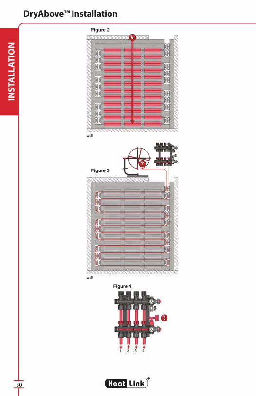
7.1 Installation
Determine the manifold location. It is recommended that manifolds be
installed before the tubing is laid.
The direction of strip hardwood fl oor must be determined before starting.
Tubing MUST be laid perpendicular to it. Use a serpentine loop pattern
with strip hardwood fl oors (see pages 32-33). For other fl oor coverings the
tubing direction doesn't matter.
If necessary, add edging for a carpet nailing strip.
Install perimeter edging on the two sides of the room (parallel with the
tubing pattern). Secure edging and sleepers to the subfl oor with either
nails or staples, as per the local building code. See the fi eld example on
pages 31-34 for suggestions.
Install the fi rst EndBend™ against the perimeter edging.
Use a 4' × 8' × 3/4" sheet of plywood, and set cut width to 6-3/4". This will
result in 7 - 6-3/4" Sleeper Strips. Install the fi rst Sleeper Strip in line with
EndBend™.
The SpacerClip™ and plate installation should be done together.
a) Sleeper the room:
• Use 6-3/4" sleepers with a 1-1/4" space between each and an EndBend™ as
required.
• The 1-1/4" space can be measured by using the SpacerClip™s, or
alternatively using plywood or small blocks cut to 1-1/4".
Tip: Install the sleeper loose enough that the SpacerClip™ or block can be
moved.
Figure 1 Figure 1

29
®
LinkHeat
INS
TA
LL
AT
ION
DryAbove™ Installation
b) Plating the room:
• Plates should be placed starting 2" from the EndBend™ and nailed on only
one edge (this will allow for plate expansion).
• Insert SpacerClip™s into the 1-1/4" slot, about 1" from the end of the plate.
• The next plate should be started about 1" from the other side of the
SpacerClip™.
• The fi nal plate may need to be cut; remove all sharp and rough edges.
• Alternatively, gap spacing between plates can be adjusted between 3" to 6"
to eliminate the need to trim the plates.
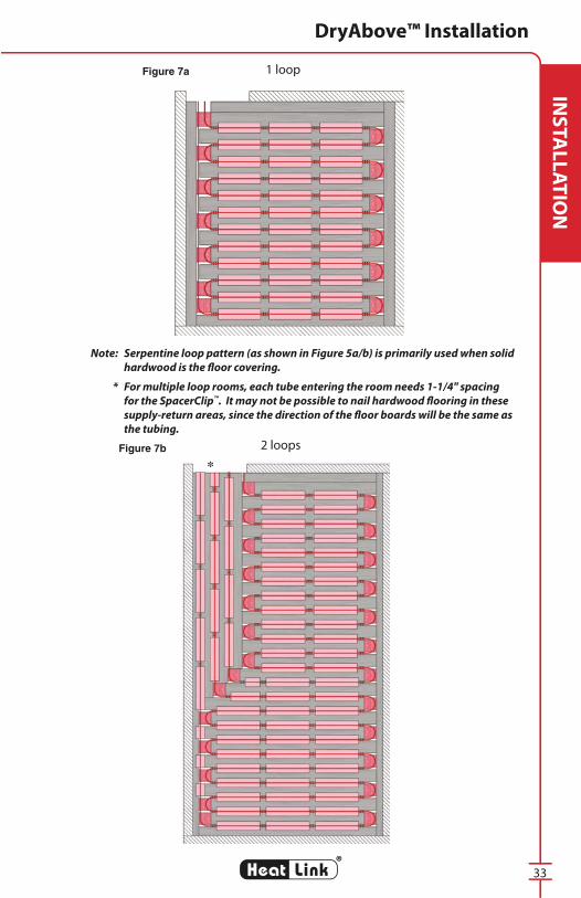
Install tubing. Use the serpentine pattern when solid hardwood is the
fi nished fl ooring. For all other fl ooring including fl oating or engineered
wood, laminate fl ooring, carpet, tiles, etc., a double counter fl ow loop
pattern is preferred. (see Figure 7 and 8 on page 33-34) Place tubing into
groove between Sleeper Strips, press into the SpacerClip™ (which will hold
the tubing in place), bend through EndBend™ and repeat.
a) To facilitate installation of PEX tubing, a tubing dispenser is recommended.
One end of the tubing roll can then be connected securely to the distribution
manifold. Tubing can then be laid by uncoiling off the dispenser
(see Figure 3).
b) Non-Barrier PEX tubing is preferred to ensure elimination of expansion /
contraction noises. If HeatLink® O2 Barrier PEX tubing is required, then a
modulating indoor / outdoor controller is required. (Alternatively, a silicon
based adhesive can be placed between the plate and tubing.)
c) To ensure supply and return tubing enters and exits out of the same side of
the room, it is preferable to have an even amount of passes (this requires an
odd amount of sleepers). If joist space access below is available, this may
not be a concern.
Perform a pressure test on the complete tubing and manifold assembly.
(The pressure test is to remain until all fl oor coverings are completed.)
(see Figure 4)
Note: When the fi nished fl oor is carpet or fl oating hardwood, the covering can be
1/4" plywood or hardboard. If a thin-set tile is to be the fi nished fl oor, use
cement board. Ensure tubing pattern is clearly marked [chalked] on the
subfl oor covering, to avoid nailing into tubing below.
7.2 Optional Insulation
For areas where the space below should not receive any heat, fasten a
minimum of 1-1/2" (40 mm) foil-backed insulation with foil facing the
subfl oor directly under the subfl oor (a high insulation R-Value of R-20 or
higher is recommended to prevent downward heatloss).
30
®
LinkHeat
INS
TA
LL
AT
ION
DryAbove™ Installation
Figure 3
Figure 2
Figure 4
wall
wall
1 2 3 4

31
®
LinkHeat
INS
TA
LL
AT
ION
DryAbove™ Installation
7.3 Installation Example
If solid hardwood will be the fi nished fl oor, lay tubing perpendicular to the
direction of the hardwood. For other fl oor coverings, tubing can be laid in
either direction.
Edging around the perimeter of a room is a function of the room size. The
number of sleepers must be an even and whole number to ensure that
the supply and return piping enters and exits on the same side of the
room. An even amount of sleepers provides an even amount of tubing
passes. To simplify calculations, do them in inches. When the math is
done, round down to the next even number. The required edging can be
calculated as follows.
1. Determine the number of sleepers fi rst
Divide the length of the wall (to which the tubing are laid perpendicular)
by 8" to get the required number of sleepers. (As each sleeper is 6-3/4"
wide, and a spacing of 1-1/4" wide is allowed between sleepers for
running the tubing, 8" is used in the calculation.) For the above right
example: 141" ÷ 8" = 17.625*. Hence, after rounding down, the number
of sleepers required for the room is 16, and the tubing will have 16 passes.
For the below right example: 96" ÷ 8" = 12 sleepers.
*Note: 17.625 falls between 18 and 16. However, the room length (11' 9"
or 141") precludes the selection of 18, as 18 × 8" = 144", and is greater than
141".
2. Edging Calculation
Using the above results, the perimeter length covered by the sleepers
can be determined by multiplying the number of sleepers by the same
8". For the above right example, the perimeter covered by the sleepers
(the sleeper coverage length) is 16 × 8" =128". To determine the edging,
subtract the sleeper coverage length from the actual wall length to be
covered by edging (141"-128" = 13"). This fi gure can be divided by 2 to
get the edging width for both ends of the room (13" ÷ 2 = 6-1/2" on each
end ). For the below right example, the sleeper coverage equals the
room width (12 × 8"= 96"). Therefore no extra edging is needed; cut a
sleeper in half to use on each side .
Hints
-If the standing wall is exposed to an unheated area (or outside), or has a
window, use a narrower edging for this wall.
-For multiple loops, perimeter edging needs to be spaced appropriately to
allow for the supply and return piping. (See Figures 7b, 8b.)
-If access to the ceiling below is possible, the supply and return runs can
alternately be drilled through the fl oor to the joist cavity below. Manifolds
are normally positioned on the same level as the tubing. However, if
access to the ceiling below is possible, alternatively the manifolds can be
positioned in the level below.

32
®
LinkHeat
INS
TA
LL
AT
ION
DryAbove™ Installation
Example Room Installation: hardwood
Example Room Installation: other
Allow a clearance of 3"-6" if carpet nailing strip required
8' or 96"
11'9"or
141"
11'9"or
141"
8' or 96"
Add nailing strip if required
Figure 5
Figure 6
33
®
LinkHeat
INS
TA
LL
AT
ION
DryAbove™ Installation
Note: Serpentine loop pattern (as shown in Figure 5a/b) is primarily used when solid
hardwood is the fl oor covering.
* For multiple loop rooms, each tube entering the room needs 1-1/4" spacing
for the SpacerClip™. It may not be possible to nail hardwood fl ooring in these
supply-return areas, since the direction of the fl oor boards will be the same as
the tubing.
1 loop
2 loops
Figure 7a
Figure 7b
*

34
®
LinkHeat
INS
TA
LL
AT
ION
DryAbove™ Installation
1 loop
2 loops
Figure 8a
Figure 8b
Note: Double Counter Flow loop pattern (as shown in Figure 6a/b) is the preferred
installation method.

35
®
LinkHeat
TE
CH
NIC
AL
8. Startup of Heating System
Note: Be climate wary! Before the system startup, ensure fl oor heating
piping is protected from freezing. This is a MUST if outside
temperatures could ever decrease to or below 32°F (0°C), see
section 8.2 for details.
8.1 Startup guidelines
Number of days after
topping is pouredSupply Water Temperature
Approximately 8-10 days Supply water temperature can be increased to 60°F (15°C).
Approximately 10-16 days Supply water temperature can be increased to 77°F (25°C).
Approximately 16 daysSupply water temperature per day can be increased by
approx. 9°F (5°C) to reach the projected maximum temperature.
Approximately 16-18 days Normal heating operations can commence.
Approximately 18-20 days Under normal heating conditions, the fl ooring can be laid*.
* These are standard industry recommendations, please confi rm the
above with your topping supplier.
Carpet, PVC (linoleum) or parquet must not be laid on the fl oor
topping until the concrete is fully cured and the moisture content is
stable. The surface temperature of the topping should be 60-65°F (15-
18°C).
Approximately 8-10 days after the topping pour, the supply water
temperature can be heated up to 60°F (15°C). During days 10-16, the
supply water temperature can be heated up to 77°F (25°C). Normal heating
operations can commence approximately 16-18 days after the topping
pour. (Note: By day 18-20, under normal heating conditions, the fl ooring
can be laid. These are standard industry recommendations, please confi rm
the above with your topping supplier).
After approximately 16 days, the supply temperature per day can
be increased by approx. 9°F (5°C) to reach the projected maximum
temperature.
Carpet, PVC (linoleum) or parquet must not be laid on the fl oor topping
until the concrete is fully cured and the moisture content is stable. The
surface temperature of the topping should be 60-65°F (15-18°C).
Ensure fl oor heating tubing is protected from freezing for system start-up
at outside temperature below 32°F (0°C). (See below)
Startup of Heating System

36
®
LinkHeat
TE
CH
NIC
AL
8.2 Chemical treatment
Inhibitors
For all systems it is suggested that inhibitors, approved for closed loop
hydronic heating systems, be added to the heating fl uid for corrosion
protection. For calculation of system water content in the particular PEX
tubing chosen for your project, please see INFO 5.
Freeze protection
For systems exposed to freezing temperatures the addition of glycols
with built-in inhibitors (that are approved for hydronic heating systems)
to the heating fl uid is required. A minimum of a 30%-35% (maximum
50%) glycol/water mixture for combination system corrosion plus freeze
protection is required. For calculation of system water content in the
particular PEX tubing chosen for the project, please see INFO 5.
Note: A water analysis should be performed annually (i.e. check
corrosion inhibitor and glycol levels) to ensure the warranty for HeatLink
components, and for the longevity of the system.
Startup of Heating System

37
®
LinkHeat
TE
CH
NIC
AL
Warranty Requirements
9. Warranty Requirements
9.1 Pressure test
For the pressure test, use at least 80-100 psi (550-690 kPa) hydrostatic
pressure or 60-80 psi (415-550 kPa) air pressure. This test must be performed
for a minimum of 12-24 hours before the placement of the topping.
Special care must be taken to check and re-tighten all joints and connections.
During the pouring of the topping, the tubing must be left under pressure so
that possible damage to the tubing can be immediately detected.
9.2 Corrosion protection
For all systems it is suggested that inhibitors, approved for closed loop
hydronic heating systems, be added to the heating fl uid for corrosion
protection. For calculation of system water content in the particular PEX
tubing chosen for your project, please see INFO 5.
9.3 Freeze protection
It is recommended for all systems exposed to freezing temperatures that
glycols with built-in inhibitors (that are approved for hydronic heating
systems) be added to the heating fl uid. A minimum of a 30%-35%
(maximum 50%) glycol/water mixture for combination system corrosion, plus
freeze protection, is needed. For a calculation of the system water content in
the particular PEX tubing chosen for the project, please see INFO 5.
9.4 System fi ll / Air purge (loop-by-loop fi ll)
It is suggested that an isolation valve be installed at each supply/return
manifold header. To fi ll the system you will need to have a minimum of 40
psi water available. As well, obtain a 5 gallon pail and 5' of hose, complete
with a hose connection end. Each loop must be fi lled individually!
Step 1 Isolate the supply and return piping with valves installed in front of
each manifold header.
Step 2 Connect the hose to the hosebib on the return manifold and drop
the end into a 5 gallon pail.
Step 3 Close all the supply and return manifold valves isolating all the
loops.
Step 4 Open the isolation valve on the supply pipe to allow water pressure
into the supply header. (Note: return isolation valve remains
closed.)
Step 5 Open the fi rst loop’s return valve. Open the fi rst loop’s supply valve
to allow water to fl ow into the loop . Watch the hose in the pail until
you observe a steady stream of water (no air or spitting). Close
loop #1’s supply valve. Repeat Step 5 for each loop until all loops
are fi lled with water, and air is purged from tubing. Purging is
complete when there is no more air and/or spitting.

38
®
LinkHeat
TE
CH
NIC
AL
Warranty Requirements, Basic Wiring
9.5 Maintenance
The following maintenance should be performed on an annual basis to
ensure the warranty for HeatLink components, and for the longevity of the
system:
1. Inspect the system for leaks and erosion of metal/plastic components
2. Retighten plastic nuts as needed
3. Water analysis (i.e. check corrosion inhibitor and/or glycol levels)
4. Sidestream fi lters should be cleaned at least once a year or when
clogged
At 10-year intervals the Shut-off Shaft Assemblies in the supply manifold
and the O-ring in the return manifold should be replaced.
10. Basic Control Wiring Requirements
10.1 Control selection
(see the StatLink guide)
10.2 Zone control
Determine if there are to be individual thermostats for each loop, or if
there is to be one thermostat controlling multiple loops. For single-zone
multiple loops, allow suffi cient space at the manifold cavity to permit the
installation of the zone valve.
10.3 Minimum wire rough-in
Even if the customer has not requested individual thermostats, it is
recommended that you rough in a minimum of 3 wires to each loop
location for future upgrade capability.

39
®
LinkHeat
DE
SIG
NHeatloss/Design
11. Heatloss/Design
11.1 Proper plans
Architectural plans, with all dimensions including elevations with window
and door specifi cations, insulation specifi cations and grade/ below grade
information, are required.
11.2 Floor coverings
Ascertain that all fl oor coverings allow for specifi c heatload calculations, i.e.
carpet versus tile or hardwood.
Carpet
Use only brand name products where the manufacturer has confi rmed the
suitability for fl oor heating. Choosing products with a minimal thermal
resistance will help ensure that feedwater temperatures remain within an
acceptable range. In order to maximize the heat transfer characteristics of a
product, it is preferable to glue carpet instead of stretching it. All adhesives
used must be suitable for fl oor heating. Under no circumstances should
adhesives made of bituminous material be used. Needle-felt carpets and
carpets with jute backs have proven to be acceptable.
Quarry tile/Ceramic tile
All tile work should be installed according to industry standards. Expansion
joints and control joints in the fl oor topping should continue through into
the tile fl oor. Under no circumstances are tiles to cross over these joints.
The expansion/control joints in the tile fl oor need to be permanently
elastic.
At a joint between a wall tile and a heated fl oor, ensure that the wall tile
terminates at 1/4” (6 mm) above the top surface of the fi nished fl oor. This
joint may be fi lled with permanently elastic material.
Vinyl/Plastic fl ooring
All vinyl/plastic fl ooring should be installed according to industry
standards.
All expansion and control joints should continue through the fl ooring to
reduce damage caused by movement of fl oor slab. All joints are to be
permanently elastic. All adhesives used must be expressly approved for
fl oor heating applications. Adhesives with a bituminous base are not to be
used for any purpose.

40
®
LinkHeat
DE
SIG
N
Hardwood fl ooring
• All hardwood fl ooring should be installed according to industry
standards and as per manufacturer instructions. Shrinkage can and
will occur in most hardwood regardless of the heating system chosen.
However, due to the presence of a low temperature heated mass in
direct contact with the hardwood, the normal shrinkage that may take
place over a 6 to 24 month period can be greatly accelerated with a
radiant fl oor heating system if the proper installation techniques have
not been followed.
• There are many types of hardwood fl ooring available including solid
planks as well as laminates. In most regions of North America laminate
fl ooring is gaining acceptance as more types/brands and fi nishes
become available. (Laminate fl ooring has several advantages over other
types of hardwood fl ooring especially when used in conjunction with
a radiant fl oor heating system. Due to the layers being manufactured
at right angles to each other (i.e. similar process as plywood sheathing),
shrinkage is nearly eliminated.
• If solid hardwood stripping is desired, and an acceptable laminate
fl ooring cannot be used, it is imperative that the hardwood has been
“acclimatized” to the region where it is being installed. Sometimes
a fl ooring supplier will receive a shipment of hardwood from a
manufacturer and then send it out to a job site within several days or
weeks. This may not be suffi cient time for the hardwood to acclimatize
to the particular region, especially in a “dry” climate area. Hardwood
must not exceed 6% to 8% moisture content at the time of installation.
It is our recommendation that all hardwood be placed on site and the
fl oor temperature increased before fl ooring installation to ensure the
proper moisture content is achieved.
• Control selection is especially critical for installations with hardwood
to ensure that proper modulation of the supply water temperature
is possible. Modulating controls will provide the lowest possible
supply water temperature for the given outside temperature. As well,
maximum fl oor surface temperature should not exceed 85°F to 90°F
(30°C to 32°C). With the variance in humidity levels through the various
seasons in a given year, supplemental humidifi cation may have to be
provided to ensure relative humidity can be maintained at 40% to 45%.
For further information and clarifi cation for your particular project,
please contact your HeatLink® representative.
• In all cases of using nail-down hardwood, the installer must be aware
of the potential for tubing damage. Tubing locations must be marked
to ensure against nails being hammered into the tubing.
11.3 Shortages
Where the heatloss has indicated a shortage in a particular room, an
alternative heat source should be selected to make up for the shortage.
This could be as simple as a towel warmer in the bath, or as complex as a
fan with heat coil.
Heatloss/Design

41
®
LinkHeat
DE
SIG
N
12. System Design and Installation
12.1 The mains
PEX tubing mains are recommended to reduce labor and architectural
impact. For a slab-on-grade installation, the mains can be buried below
or within the slab. For a wet or dry on plywood application, the mains can
be installed within the joist cavity. Always allow for the expansion and
contraction of the mains, as the temperature fl uctuates. It is recommended
that the tubing be allowed free movement and is not fastened directly to
the fl oor joists.
12.2 Requirements of a hydronic control system
The intent of a hydronic heating control system is to achieve heating
comfort, system protection, energy saving and ease of use.
Heating comfort is achieved by:
• keeping proper system temperatures, and
• directing the right amount of heat when and where you want it.
System protection is achieved by:
• protecting the primary heat source (e.g. boiler) from corrosion and thermal
shock, and
• reducing equipment cycling.
Energy saving is achieved by:
• running the system at the lowest water temperature possible,
• turning off the system when no heat is demanded, and
• minimizing boiler short cycling.
Ease of use is achieved by:
• running automatic functions in lieu of manual settings, and
• providing easy and consistent wiring and installation procedures.
Design and Installation Requirements

42
®
LinkHeat
NO
TE
SNotes
________________________________________________________________________________________________________________________________________________________________________________________________________________________________________________________________________________________________________________________________________________________________________________________________________________________________________________________________________________________________________________________________________________________________________________________________________________________________________________________________________________________________________________________________________________________________________________________________________________________________________________________________________________________________________________________________________________________________________________________________________________________________________________________________________________________________________________________________________________________________________________________________________________________________________________________________________________________________________________________________________________________________________________________________________________________________________________________________________________________________________________________________________________________________________________________________________________________________________________________________________________________________________________________________________________________________________________________________________________________________________________________________________________________________________________________________________________________________________________________________________________________


www.heatlinkgroup.com
L3390 © HeatLink Group Inc.Printed in USA
HeatLink, StatLink, DryAbove, DryBelow, EndBend, SpacerClip are either registered trademarks or trademarks of HeatLink Group Inc.
®
Heat Link
May
11
, 20
11