Embed Size (px)
Citation preview
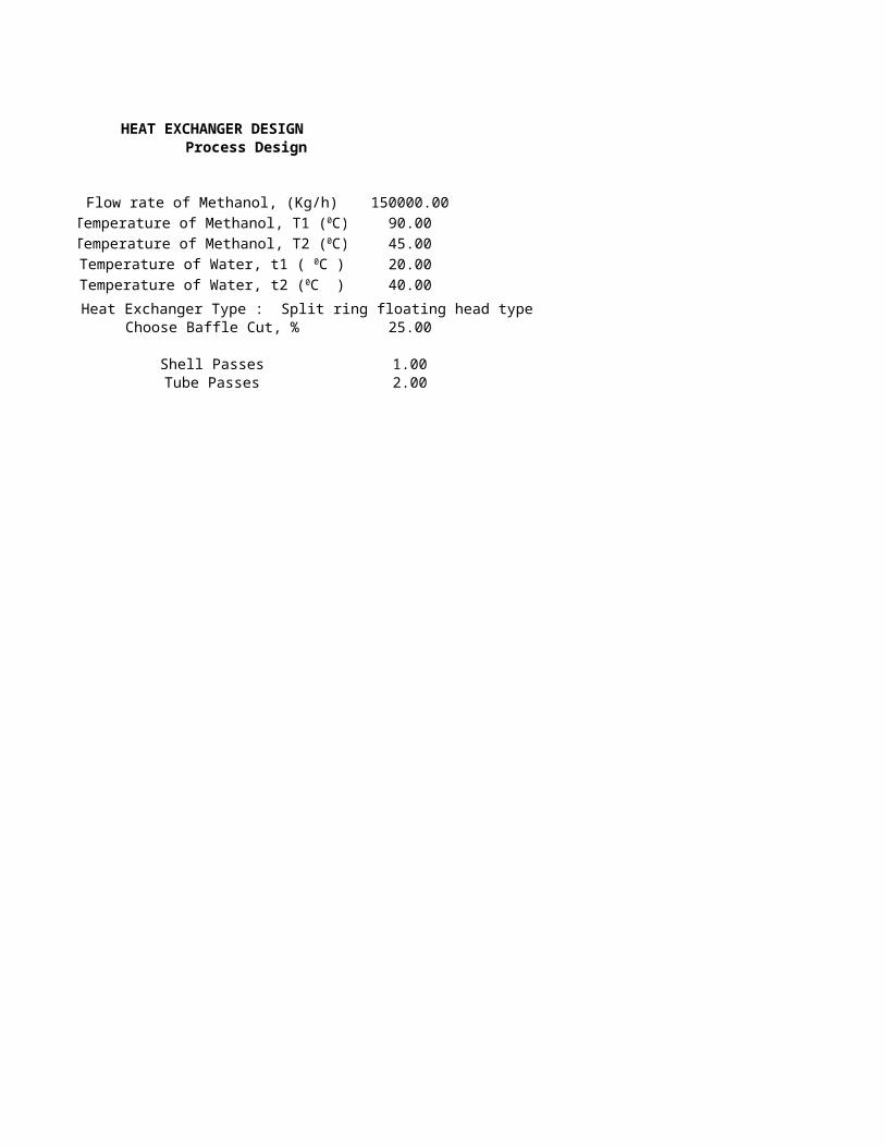
HEAT EXCHANGER DESIGN Process Design
Flow rate of Methanol, (Kg/h) 150000.00
90.00
45.00
20.00
40.00
Heat Exchanger Type : Split ring floating head typeChoose Baffle Cut, % 25.00
Shell Passes 1.00Tube Passes 2.00
Temperature of Methanol, T1 (0C)
Temperature of Methanol, T2 (0C)
Temperature of Water, t1 ( 0C )
Temperature of Water, t2 (0C )
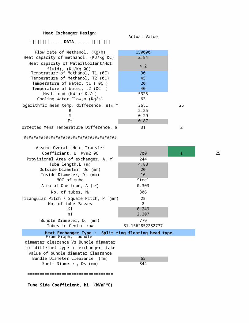
Heat Exchanger Design:Actual Value
Flow rate of Methanol, (Kg/h) 150000Heat capacity of methanol, (KJ/Kg 0C) 2.84
4.2
Temperature of Methanol, T1 (0C) 90Temperature of Methanol, T2 (0C) 45
Temperature of Water, t1 ( 0C ) 20Temperature of Water, t2 (0C ) 40
Heat Load (KW or KJ/s) 5325Cooling Water Flow,m (Kg/s) 63
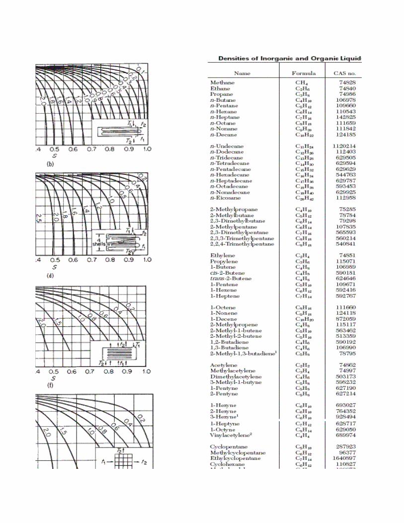
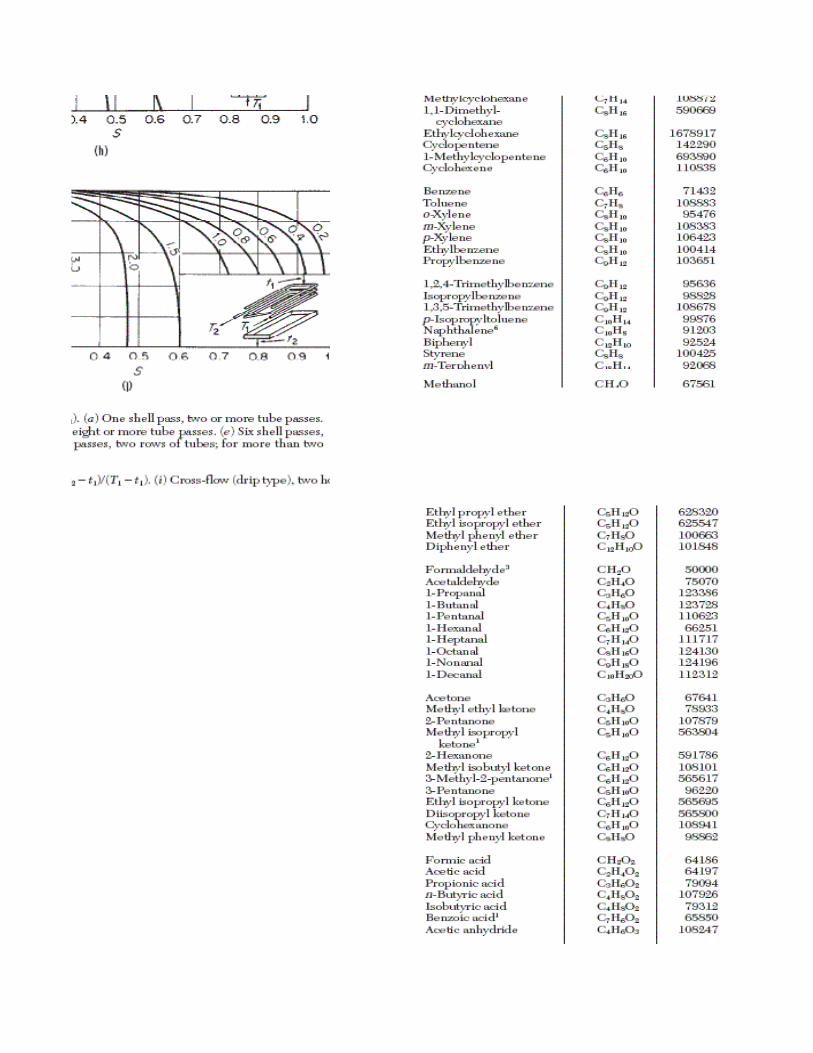
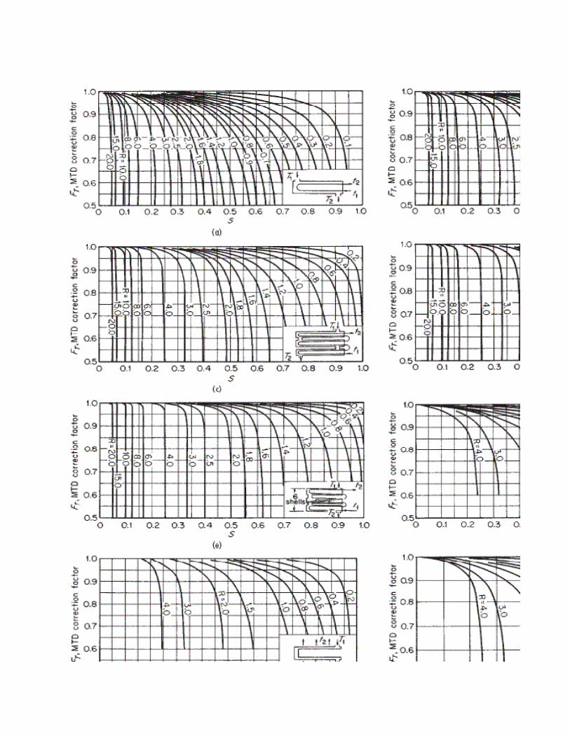
36.1 25R 2.25S 0.29Ft 0.87
31 2
######################################
700 1 25
244Tube length,L (m) 4.83
Outside Diameter, Do (mm) 20Inside Diameter, Di (mm) 16
MOC of tube Steel
0.303
806
25No. of tube Passes 2
K1 0.249n1 2.207
779Tubes in Centre row 31.1562852282777
Heat Exchanger Type : Split ring floating head type
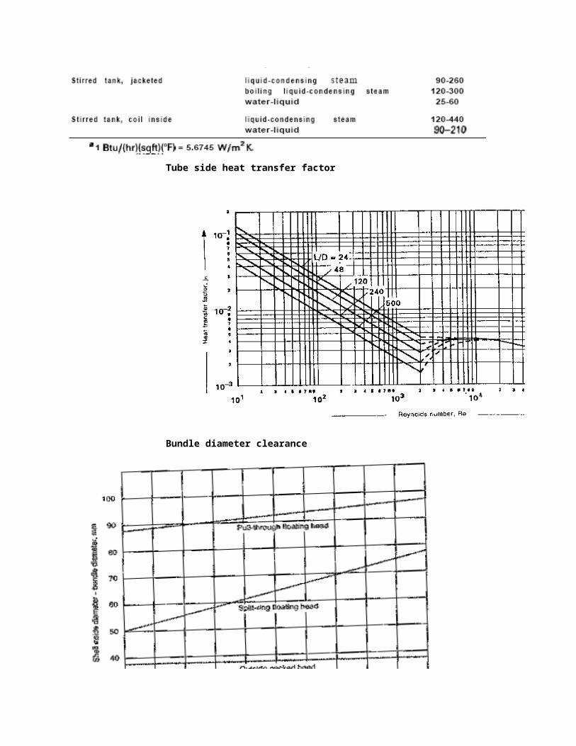
Bundle Diameter Clearance (mm) 65Shell Diameter, Ds (mm) 844
===================================
||||||||------DATA-------||||||||
Heat capacity of Water(Coolant/Hot fluid), (KJ/Kg 0C)
Logarithmic mean temp. difference, ΔTlm, 0C
Corrected Mena Temperature Difference, ΔTm
Assume Overall Heat Transfer Coefficient, U W/m2 0C
Provisional Area of exchanger, A, m2
Area of One tube, A (m2)
No. of tubes, NT
Triangular Pitch / Square Pitch, Pt (mm)
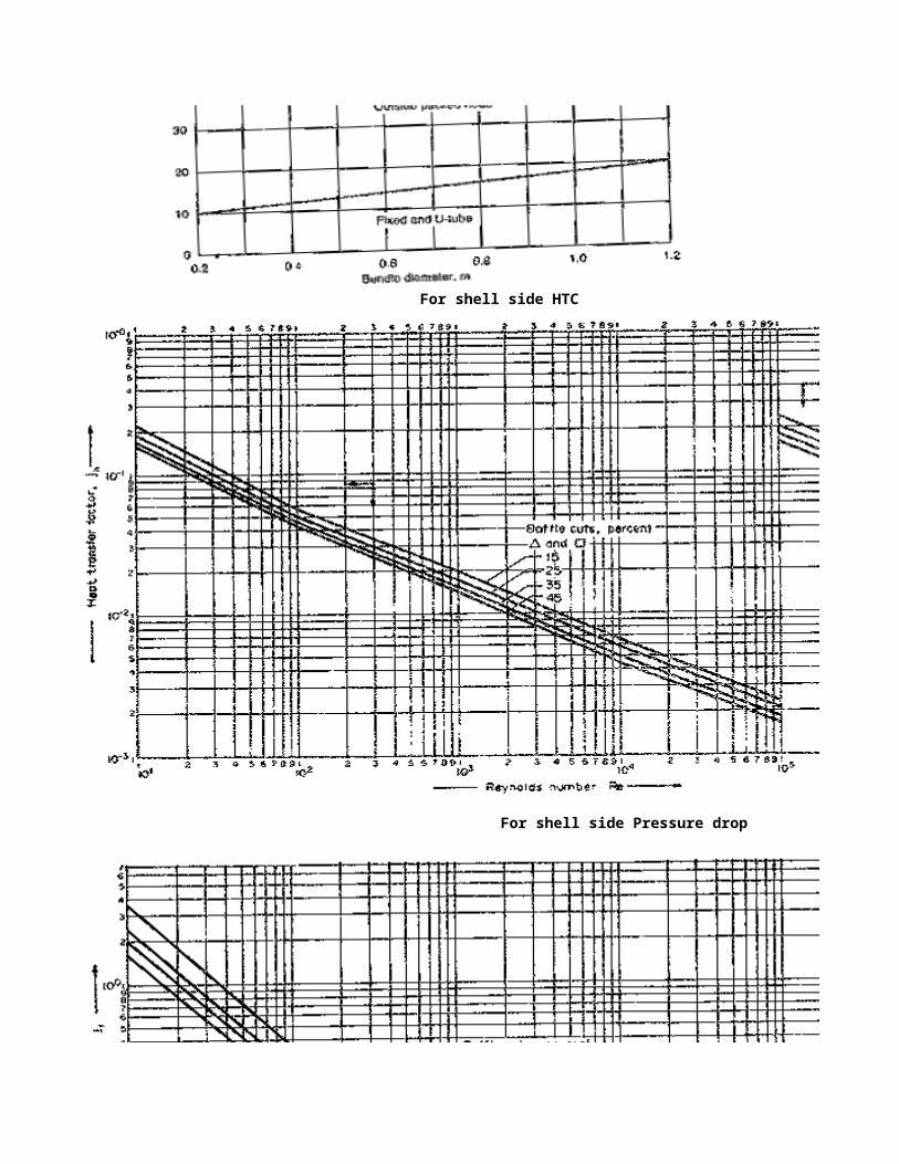
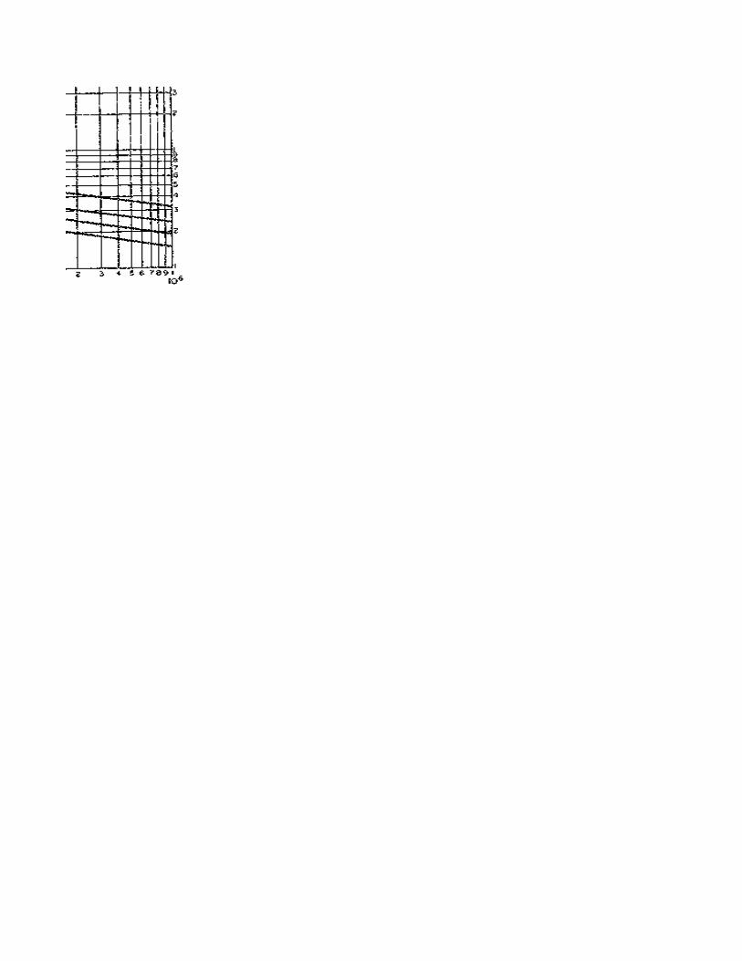
Bundle Diameter, Db (mm)
From Graph, bundle diameter clearance Vs Bundle diameter for
differnet type of exchanger, take value of bundle diameter Clearance
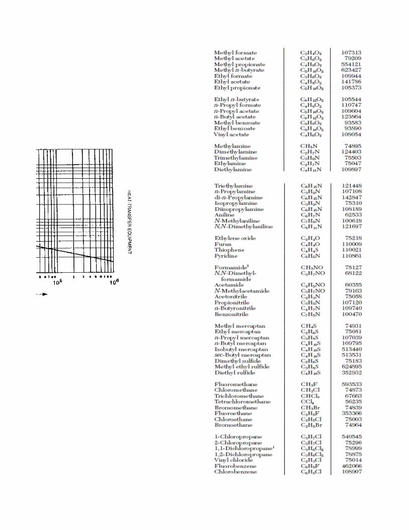
Tube Side Coefficient, hi, (W/m2 0C)
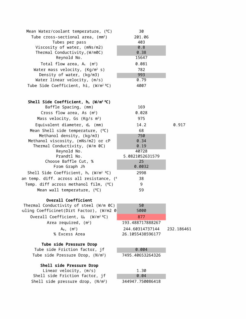
30
201.06Tubes per pass 403
Viscosity of water, (mNs/m2) 0.8Thermal Conductivity,(W/m0C) 0.38
Reynold No. 15647
0.081
782Density of water, (kg/m3) 993
Water linear velocity, (m/s) 0.79
4007
Baffle Spacing, (mm) 169
0.028
975
14.2 0.917
68Methanol density, (kg/m3) 750
Methanol viscosity, (mNs/m2) or cP 0.34Thermal Conductivity, (W/m 0C) 0.19
Reynold No. 40728Prandtl No. 5.0821052631579
Choose Baffle Cut, % 25From Graph Jh 0.0032
2998
38
9
59
Overall CoefficientThermal Conductivity of steel (W/m 0C) 50
Fouling Coefficinet(Dirt Factor), (W/m2 0C) 5000
877
193.488717888267
244.60314737144 232.186461% Excess Area 26.1055438596177
Tube side Pressure DropTube side Friction factor, jf 0.004
7495.40653264326
Shell side Pressure DropLinear velocity, (m/s) 1.30
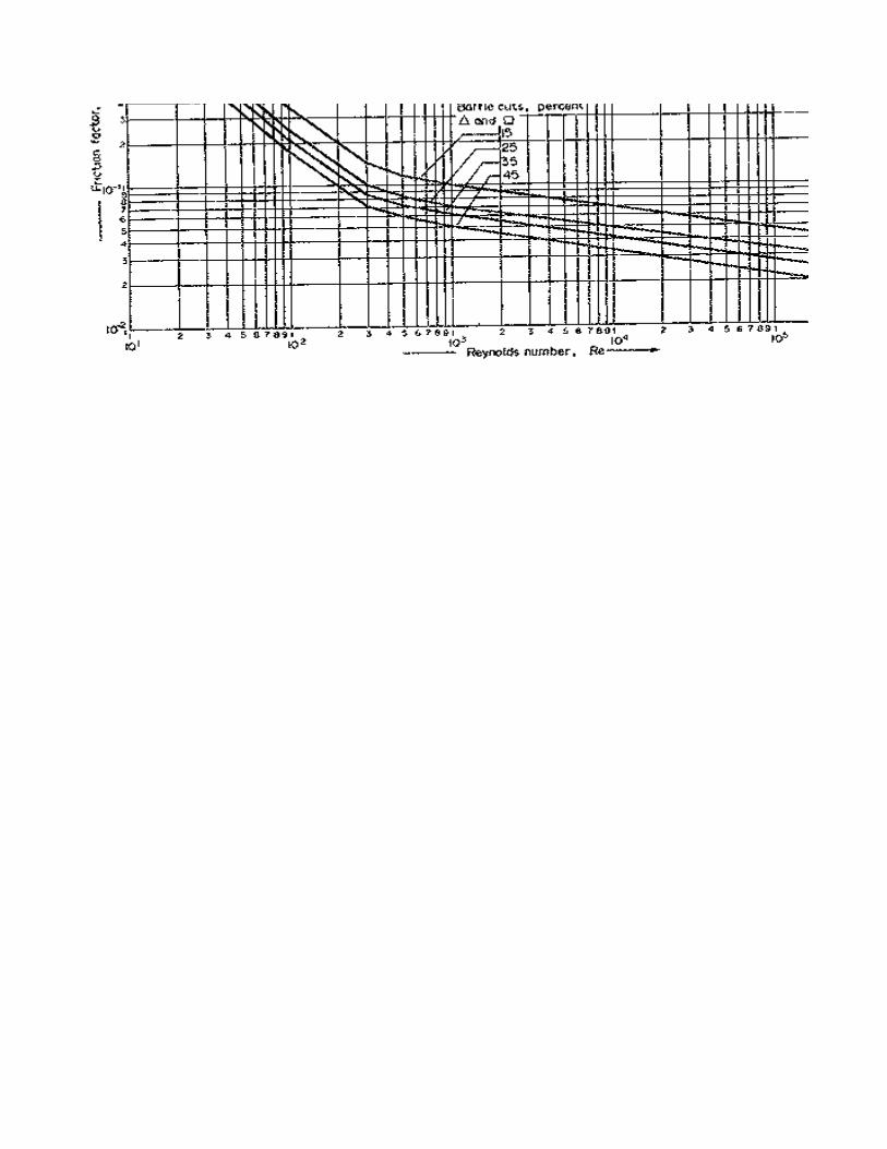
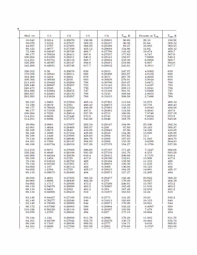
Shell side Friction factor, jf 0.04
344947.750086418
Mean Water/coolant temperature, (0C)
Tube cross-sectional area, (mm2)
Total flow area, At (m2)
Water mass velocity, (Kg/m2 s)
Tube Side Coefficient, hi, (W/m2 0C)
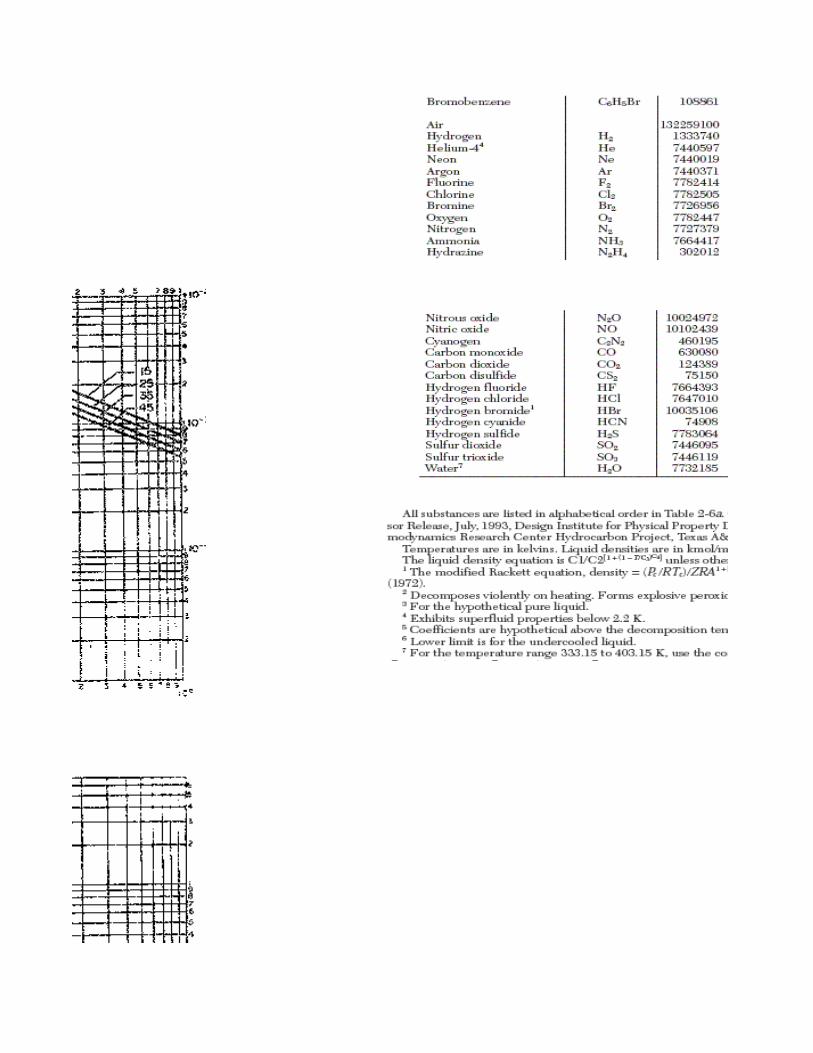
Shell Side Coefficient, hs (W/m2 0C)
Cross flow area, As (m2)
Mass velocity, Gs (Kg/s m2)
Equivalent diameter, de (mm)
Mean Shell side temperature, (0C)
Shell Side Coefficient, hs (W/m2 0C)
Mean temp. diff. across all resistance, (0C)
Temp. diff across methanol film, (0C)
Mean wall temperature, (0C)
Overall Coefficient, U0 (W/m2 0C)
Area required, (m2)
A0, (m2)
Tube side Pressure Drop, (N/m2)
Shell side pressure drop, (N/m2)

86236.9375216046 86.2369375
1721.85567343498
Pressure drop reduction,shell side,(N/m2)
heat transfer coefficient,shell side, w/m2 0C
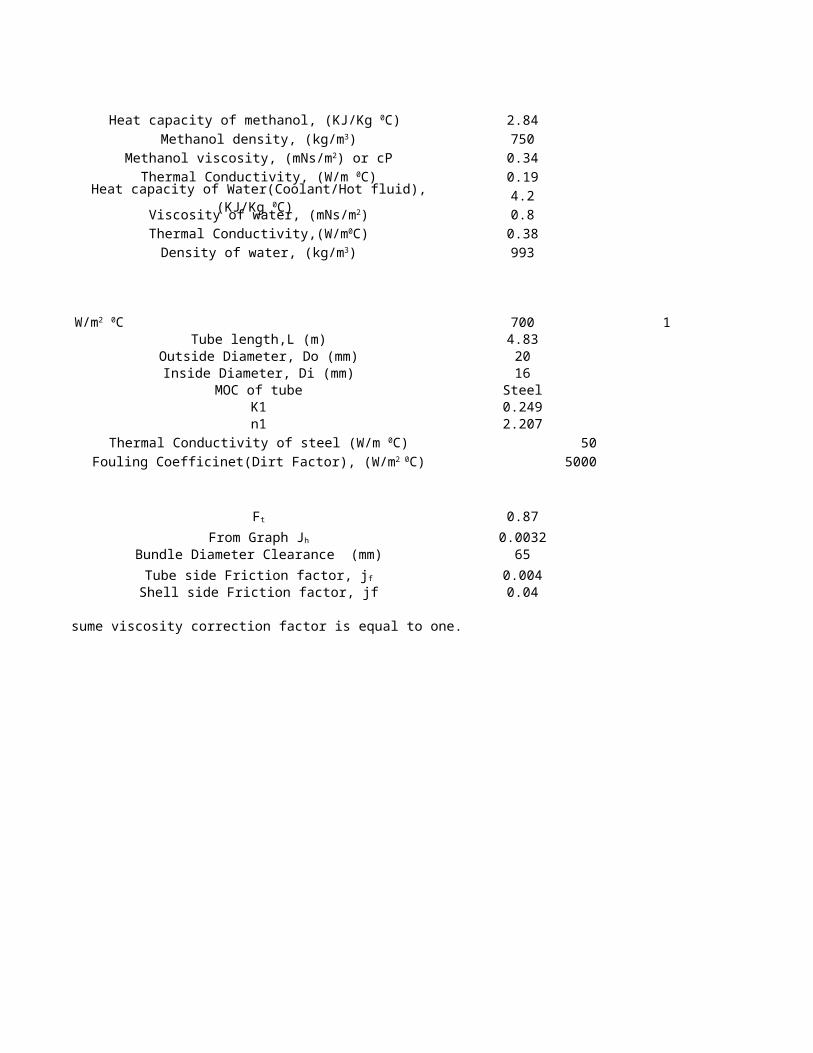
2.84
750
0.34
0.19
4.2
0.8
0.38
993
700 1 25Tube length,L (m) 4.83
Outside Diameter, Do (mm) 20Inside Diameter, Di (mm) 16
MOC of tube SteelK1 0.249 0.917n1 2.207
50
5000
0.87
0.0032Bundle Diameter Clearance (mm) 65
0.004Shell side Friction factor, jf 0.04
Assume viscosity correction factor is equal to one.
Heat capacity of methanol, (KJ/Kg 0C)
Methanol density, (kg/m3)
Methanol viscosity, (mNs/m2) or cP
Thermal Conductivity, (W/m 0C)
Heat capacity of Water(Coolant/Hot fluid), (KJ/Kg 0C) Viscosity of water, (mNs/m2)
Thermal Conductivity,(W/m0C)
Density of water, (kg/m3)
Assume Overall Heat Transfer Coefficient, U W/m2 0C
Thermal Conductivity of steel (W/m 0C)
Fouling Coefficinet(Dirt Factor), (W/m2 0C)
Ft
From Graph Jh
Tube side Friction factor, jf

temp. F to C, K and R 36.6666666666667 309.6666667 557.4 98heat capacity cal/mol K to KJ/kg C 2.84 18pressure N/m2 to kpa and bar 68.409 684.09 68409pressure mm Hg to psf, psi,N/m2 1428.75251525227 9.921892466 68409.04 513.11Density of liq, g/cc to kg/m3 790 0.79liquid density, (kg/m3) 992.896136057145 30 303 5.459
0.30542647.130.081
Thermal Conductivity, (W/m C) 0.382134220081

1.950133
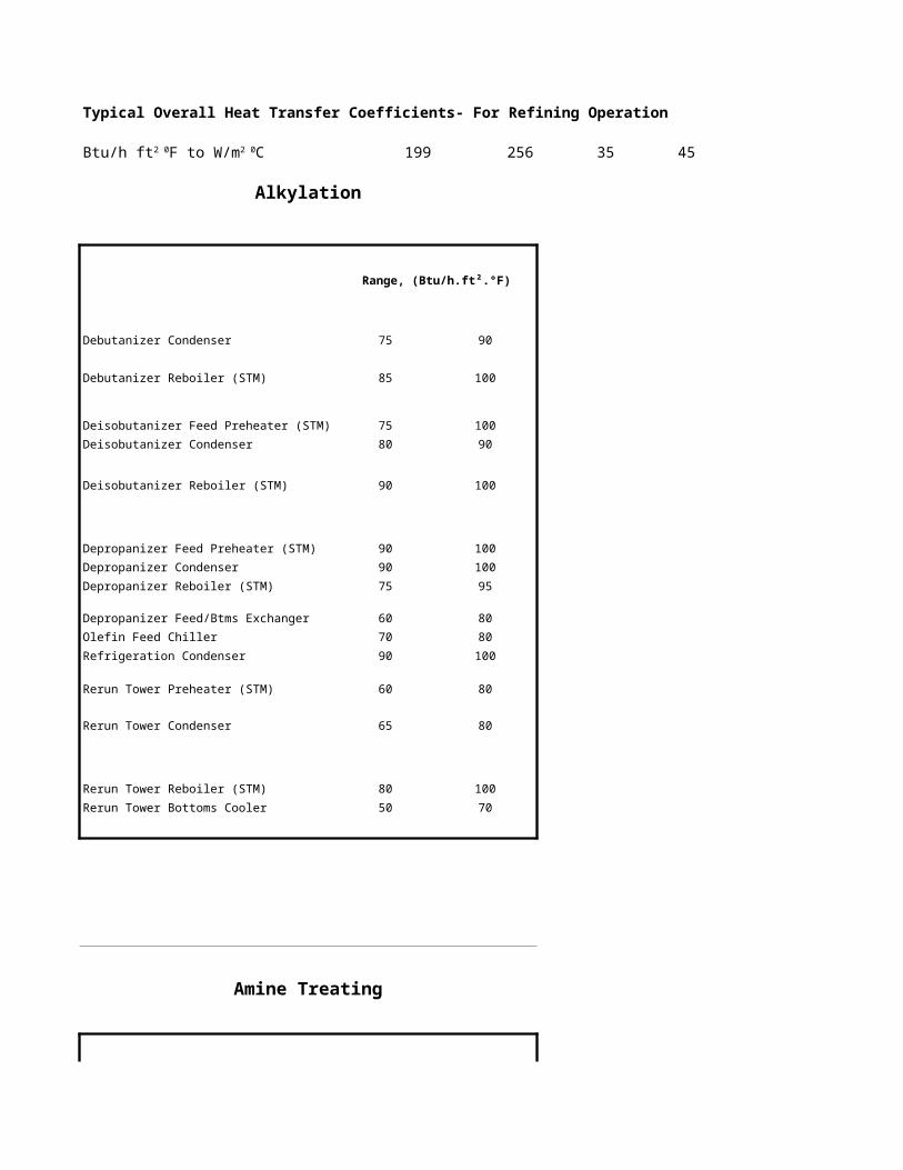
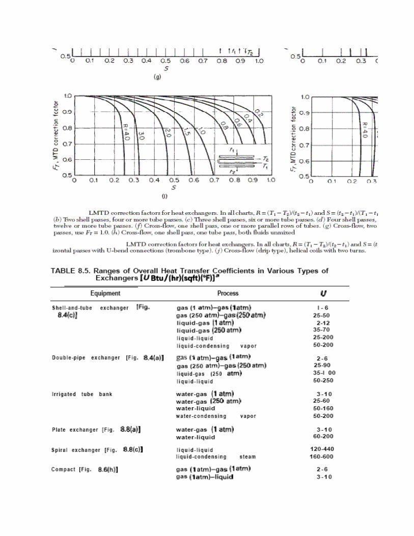
Typical Overall Heat Transfer Coefficients- For Refining Operation
199 256 35 45
Alkylation
Range, (Btu/h.ft².°F)
Debutanizer Condenser 75 90
Debutanizer Reboiler (STM) 85 100
Deisobutanizer Feed Preheater (STM) 75 100
Deisobutanizer Condenser 80 90
Deisobutanizer Reboiler (STM) 90 100
Depropanizer Feed Preheater (STM) 90 100
Depropanizer Condenser 90 100
Depropanizer Reboiler (STM) 75 95
Depropanizer Feed/Btms Exchanger 60 80
Olefin Feed Chiller 70 80
Refrigeration Condenser 90 100
Rerun Tower Preheater (STM) 60 80
Rerun Tower Condenser 65 80
Rerun Tower Reboiler (STM) 80 100
Rerun Tower Bottoms Cooler 50 70
Amine Treating
Btu/h ft2 0F to W/m2 0C
Range, (Btu/h.ft².°F)
Rich/Lean Amine Exchanger 75 90
Regenerator Condenser 70 90
Regenerator Reboiler (STM) 100 120
Lean Amine Cooler 80 90
Organic(non-condensable)
Catalytic Cracking
Range, (Btu/h.ft².°F)
Naphtha Cooler 55 65
Feed / DFO 35 45
DFO Cooler 45 55
DFO Cooler (300-400 °F) 80 100
Gas Oil / DFO 40 50
Gas Oil / Quench 35 50
Gas Oil / Tar 30 40
Quench or STB / Feed 35 45
Quench / BFW 60 80
Quench or STB Cooler 30 50
50 70
Quench Steam Gen. 70 90
Reduced Crude / Quench 35 45
Reduced Crude / Tar Sep. Btms. 30 40
SYN Tower Condenser 30 40
Crude Distillation
Range, (Btu/h.ft².°F)
Crude / Heavy Gas Oil 40 50
Quench and/or STB Cooler (300-400 °F)

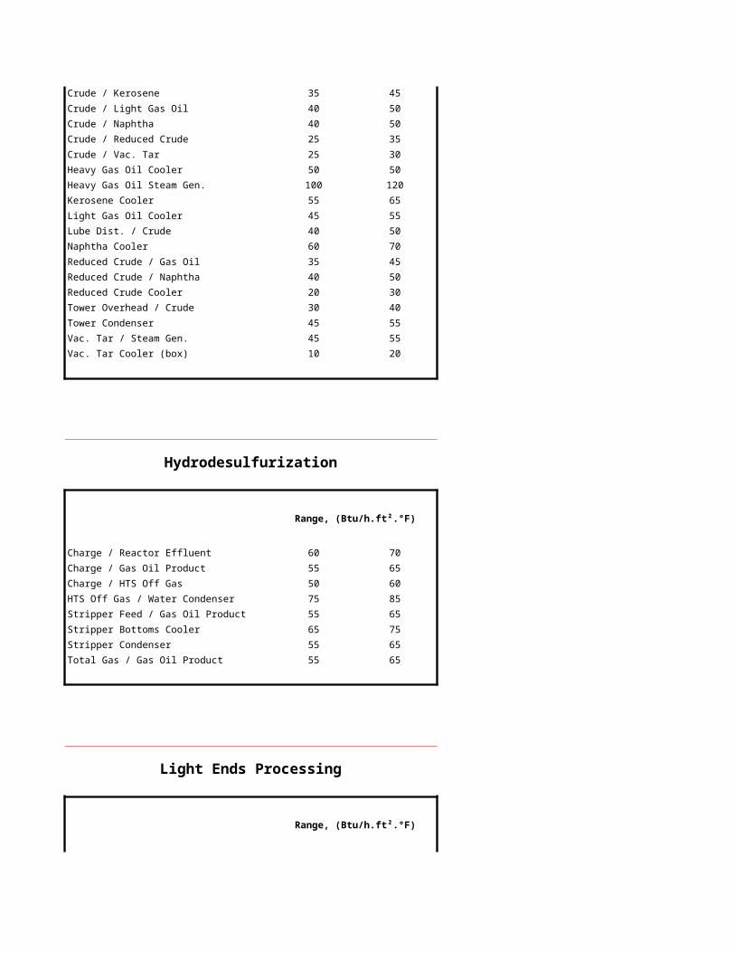
Crude / Kerosene 35 45
Crude / Light Gas Oil 40 50
Crude / Naphtha 40 50
Crude / Reduced Crude 25 35
Crude / Vac. Tar 25 30
Heavy Gas Oil Cooler 50 50
Heavy Gas Oil Steam Gen. 100 120
Kerosene Cooler 55 65
Light Gas Oil Cooler 45 55
Lube Dist. / Crude 40 50
Naphtha Cooler 60 70
Reduced Crude / Gas Oil 35 45
Reduced Crude / Naphtha 40 50
Reduced Crude Cooler 20 30
Tower Overhead / Crude 30 40
Tower Condenser 45 55
Vac. Tar / Steam Gen. 45 55
Vac. Tar Cooler (box) 10 20
Hydrodesulfurization
Range, (Btu/h.ft².°F)
Charge / Reactor Effluent 60 70
Charge / Gas Oil Product 55 65
Charge / HTS Off Gas 50 60
HTS Off Gas / Water Condenser 75 85
Stripper Feed / Gas Oil Product 55 65
Stripper Bottoms Cooler 65 75
Stripper Condenser 55 65
Total Gas / Gas Oil Product 55 65
Light Ends Processing
Range, (Btu/h.ft².°F)
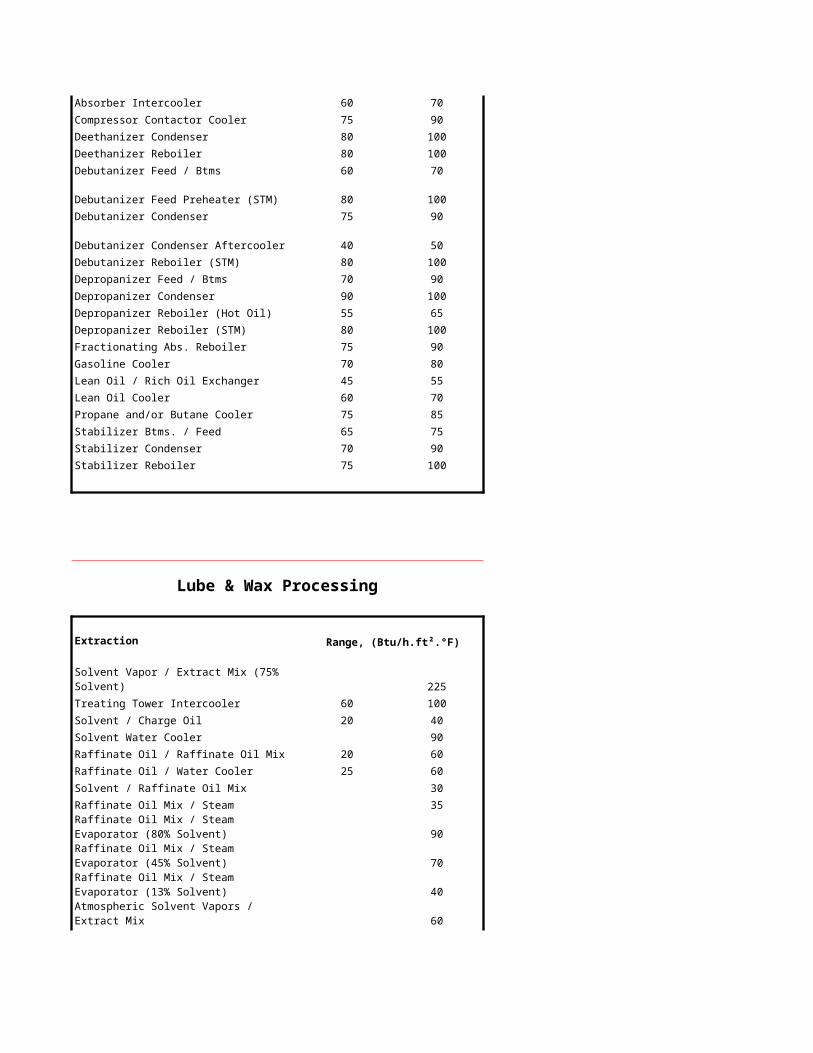
Absorber Intercooler 60 70
Compressor Contactor Cooler 75 90
Deethanizer Condenser 80 100
Deethanizer Reboiler 80 100
Debutanizer Feed / Btms 60 70
Debutanizer Feed Preheater (STM) 80 100
Debutanizer Condenser 75 90
Debutanizer Condenser Aftercooler 40 50
Debutanizer Reboiler (STM) 80 100
Depropanizer Feed / Btms 70 90
Depropanizer Condenser 90 100
Depropanizer Reboiler (Hot Oil) 55 65
Depropanizer Reboiler (STM) 80 100
Fractionating Abs. Reboiler 75 90
Gasoline Cooler 70 80
Lean Oil / Rich Oil Exchanger 45 55
Lean Oil Cooler 60 70
Propane and/or Butane Cooler 75 85
Stabilizer Btms. / Feed 65 75
Stabilizer Condenser 70 90
Stabilizer Reboiler 75 100
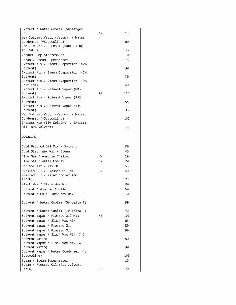
Lube & Wax Processing
Extraction Range, (Btu/h.ft².°F)
225
Treating Tower Intercooler 60 100
Solvent / Charge Oil 20 40
Solvent Water Cooler 90
Raffinate Oil / Raffinate Oil Mix 20 60
Raffinate Oil / Water Cooler 25 60
Solvent / Raffinate Oil Mix 30
Raffinate Oil Mix / Steam 35
90
70
40
60
Solvent Vapor / Extract Mix (75% Solvent)
Raffinate Oil Mix / Steam Evaporator (80% Solvent)
Raffinate Oil Mix / Steam Evaporator (45% Solvent)
Raffinate Oil Mix / Steam Evaporator (13% Solvent)
Atmospheric Solvent Vapors / Extract Mix
10 15
60
120
Vacuum Pump Aftercooler 10
Steam / Steam Superheater 15
90
70
40
90 115
55
35
105
15
Dewaxing
Cold Pressed Oil Mix / Solvent 30
Cold Slack Wax Mix / Steam 45
Flue Gas / Ammonia Chiller 6 10
Flue Gas / Water Cooler 10 20
Hot Solvent / Wax Oil 65
Pressed Oil / Pressed Oil Mix 30 40
Pressed Oil / Water Cooler (to 150°F) 25
Slack Wax / Slack Wax Mix 30
Solvent / Ammonia Chiller 60
Solvent / Cold Slack Wax Mix 10
Solvent / Water Cooler (5# delta P) 90
Solvent / Water Cooler (1# delta P) 70
Solvent Vapor / Pressed Oil Mix 45 100
Solvent Vapor / Slack Wax Mix 65
Solvent Vapor / Pressed Oil 80
Solvent Vapor / Pressed Oil 90
80
90
100
Steam / Steam Superheater 15
Steam / Pressed Oil (2:1 Solvent Ratio) 15 70
Extract / Water Cooler (Submerged Coil)
Dry Solvent Vapor (Vacuum) / Water Condenser (+Subcooling)
CBM / Water Condenser (Subcooling to 150°F)
Extract Mix / Steam Evaporator (80% Solvent)
Extract Mix / Steam Evaporator (45% Solvent)
Extract Mix / Steam Evaporator (13% Solv ent)
Extract Mix / Solvent Vapor (80% Solvent)
Extract Mix / Solvent Vapor (45% Solvent)
Extract Mix / Solvent Vapor (13% Solvent)
Wet Solvent Vapor (Vacuum) / Water Condenser (+Subcooling)
Extract Mix (10% Solvent) / Extract Mix (80% Solvent)
Solvent Vapor / Slack Wax Mix (3:1 Solvent Ratio)
Solvent Vapor / Slack Wax Mix (4:1 Solvent Ratio)
Solvent Vapor / Water Condenser (No Subcooling)
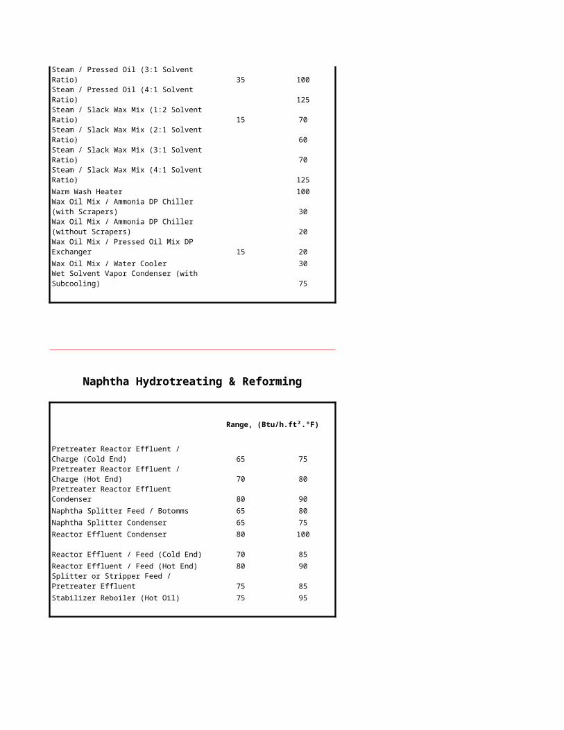
Steam / Pressed Oil (3:1 Solvent Ratio) 35 100
Steam / Pressed Oil (4:1 Solvent Ratio) 125
15 70
60
70
125
Warm Wash Heater 100
30
20
15 20
Wax Oil Mix / Water Cooler 30
75
Naphtha Hydrotreating & Reforming
Range, (Btu/h.ft².°F)
65 75
70 80
Pretreater Reactor Effluent Condenser 80 90
Naphtha Splitter Feed / Botomms 65 80
Naphtha Splitter Condenser 65 75
Reactor Effluent Condenser 80 100
Reactor Effluent / Feed (Cold End) 70 85
Reactor Effluent / Feed (Hot End) 80 90
75 85
Stabilizer Reboiler (Hot Oil) 75 95
Steam / Slack Wax Mix (1:2 Solvent Ratio)
Steam / Slack Wax Mix (2:1 Solvent Ratio)
Steam / Slack Wax Mix (3:1 Solvent Ratio)
Steam / Slack Wax Mix (4:1 Solvent Ratio)
Wax Oil Mix / Ammonia DP Chiller (with Scrapers)
Wax Oil Mix / Ammonia DP Chiller (without Scrapers)
Wax Oil Mix / Pressed Oil Mix DP Exchanger
Wet Solvent Vapor Condenser (with Subcooling)
Pretreater Reactor Effluent / Charge (Cold End)
Pretreater Reactor Effluent / Charge (Hot End)
Splitter or Stripper Feed / Pretreater Effluent
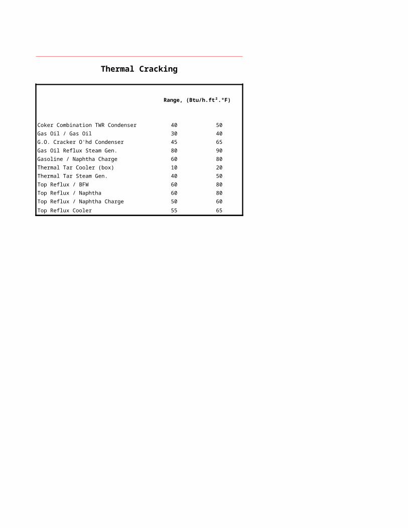
Thermal Cracking
Range, (Btu/h.ft².°F)
Coker Combination TWR Condenser 40 50
Gas Oil / Gas Oil 30 40
G.O. Cracker O'hd Condenser 45 65
Gas Oil Reflux Steam Gen. 80 90
Gasoline / Naphtha Charge 60 80
Thermal Tar Cooler (box) 10 20
Thermal Tar Steam Gen. 40 50
Top Reflux / BFW 60 80
Top Reflux / Naphtha 60 80
Top Reflux / Naphtha Charge 50 60
Top Reflux Cooler 55 65
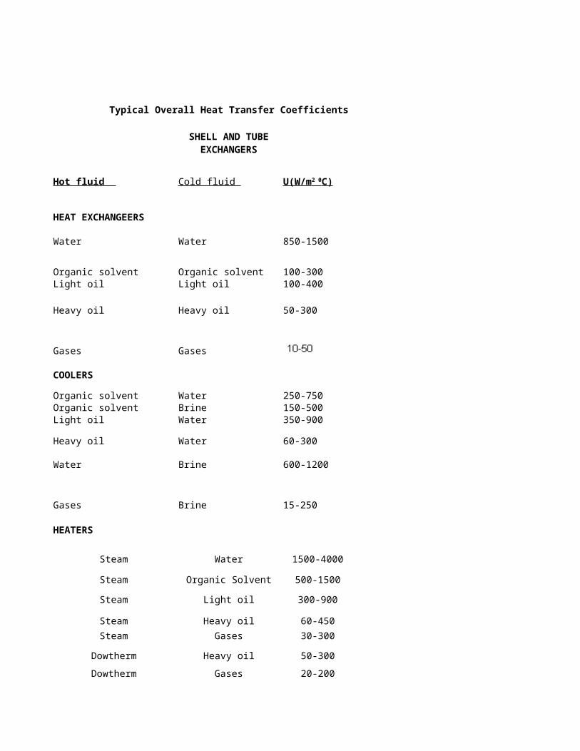
Typical Overall Heat Transfer Coefficients
Hot fluid Cold fluid
HEAT EXCHANGEERS
Water Water 850-1500
Organic solvent Organic solvent 100-300Light oil Light oil 100-400
Heavy oil Heavy oil 50-300
Gases Gases
COOLERS
Organic solvent Water 250-750Organic solvent Brine 150-500Light oil Water 350-900
Heavy oil Water 60-300
Water Brine 600-1200
Gases Brine 15-250
HEATERS
Steam Water 1500-4000
Steam Organic Solvent 500-1500
Steam Light oil 300-900
Steam Heavy oil 60-450
Steam Gases 30-300
Dowtherm Heavy oil 50-300
Dowtherm Gases 20-200
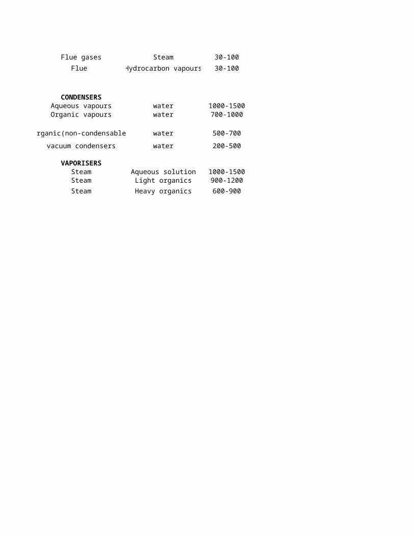
SHELL AND TUBE EXCHANGERS
U(W/m 2 0C)
Flue gases Steam 30-100
Flue Hydrocarbon vapours 30-100
CONDENSERSAqueous vapours water 1000-1500Organic vapours water 700-1000
Organic(non-condensable) water 500-700
vacuum condensers water 200-500
VAPORISERSSteam Aqueous solution 1000-1500Steam Light organics 900-1200
Steam Heavy organics 600-900
Tube side heat transfer factor
Bundle diameter clearance
For shell side HTC
For shell side Pressure drop