Embed Size (px)
Citation preview

H E A R TSTA R T X LTI N ST R U C T I O N S F O R U S E
M3500B


Instructions for Use
�������������� �������������������

ii
������About This EditionEdition 3Printed in the USAPublication number M3500-91900
The information in this guide applies to the M3500B HeartStart XLT, release Main 35 and earlier. This information is subject to change without notice.
Philips Medical Systems shall not be liable for errors contained herein or for incidental or consequential damages in connection with the furnishing, perfor-mance, or use of this material.
Edition HistoryEdition 1, January 3, 2000Edition 2, May 15, 2000Edition 3, October 30, 2002
CopyrightCopyright © 2002Philips Electronics North AmericaCorporation3000 Minuteman Road Andover, MA USA 01810-1099(978) 687-1501
All rights are reserved. Reproduction in whole or in part is prohibited without the prior written consent of the copy-right holder.
SMART Biphasic is a registered trade-mark of Philips Medical Systems.
Use of supplies or accessories other than those recommended by Philips Medical Systems may compromise product performance.
THIS PRODUCT IS NOT INTENDED FOR HOME USE.
IN THE U.S., FEDERAL LAW RESTRICTS THIS DEVICE TO SALE ON OR BY THE ORDER OF A PHY-SICIAN.
Medical Device DirectiveThe M3500B HeartStart XLT Defibril-lator/Monitor complies with the requirements of the Medical Device Directive 93/42/EEC and carries the
0123 mark accordingly.
Authorized EU-representative:
Philips Medizinsysteme Böblingen GmbHHewlett Packard Str. 271034 BöblingenGermany
Canada EMC:ICES-001
Device TrackingIn the USA, the Food and Drug Admin-istration requires defibrillator manufac-turers and distributors to track the location of their defibrillators. If your defibrillator has been sold, donated, lost, stolen, exported, or destroyed, or if it was not obtained directly from Philips Medical Systems, please notify Philips Medical Systems at (978) 659-3202.
iii
Conventions
This guide uses the following conventions:
WARNING Warning statements describe conditions or actions that can result in personal injury or loss of life.
CAUTION Caution statements describe conditions or actions that can result in damage to the equipment or loss of data.
NOTE Notes contain additional information on usage.
���� represents messages that appear on the display
represents softkey labels that appear on the display above or below the button to which they correspond
�����


Contents
Introduction
Overview ............................................................................................................................... 1-1Intended Use ......................................................................................................................... 1-3Defibrillation Therapy .......................................................................................................... 1-3
Indications for AED Therapy ......................................................................................... 1-3Contraindications for AED Therapy ............................................................................... 1-4Precautions for AED Therapy ......................................................................................... 1-4Indications for Manual Defibrillation Therapy ............................................................... 1-4Contraindications for Manual Defibrillation Therapy .................................................... 1-5Precautions for Manual Defibrillation Therapy .............................................................. 1-5
Noninvasive Pacing Therapy ................................................................................................ 1-5Indications ....................................................................................................................... 1-5Contraindications ............................................................................................................ 1-5
SpO2 Monitoring .................................................................................................................. 1-6Indications ....................................................................................................................... 1-6Contraindications ............................................................................................................ 1-6
Learning to Use the HeartStart XLT ..................................................................................... 1-7Safety Considerations ........................................................................................................... 1-7
Getting Started
Getting Acquainted ............................................................................................................... 2-1Basic Orientation ............................................................................................................ 2-2Manual Mode Controls ................................................................................................... 2-4LCD Backlight ................................................................................................................ 2-8
Connecting to Power ............................................................................................................. 2-9Inserting the Battery ........................................................................................................ 2-9Removing the Battery ................................................................................................... 2-10Low Battery Warning ................................................................................................... 2-10
Using a Data Card ............................................................................................................... 2-11Inserting a Data Card .................................................................................................... 2-12Removing a Data Card .................................................................................................. 2-13
v

Contents
Defibrillating in AED Mode
Overview ............................................................................................................................... 3-3Defibrillation (with the default configuration) ............................................................... 3-3Defibrillation (with a modified configuration) ............................................................... 3-4
Preparation ............................................................................................................................ 3-5Defibrillating ......................................................................................................................... 3-6
Automatic Re-analysis On ...................................................................................... 3-11Automatic Re-analysis Off ..................................................................................... 3-11
Pausing for CPR ................................................................................................................. 3-12Monitoring Rhythm ............................................................................................................ 3-14ERC Protocol ...................................................................................................................... 3-16Troubleshooting .................................................................................................................. 3-18
Monitoring the ECG
Applying Monitoring Electrodes .......................................................................................... 4-2Electrode Placement ....................................................................................................... 4-3
Selecting the Lead ................................................................................................................. 4-5Setting the Heart Rate Alarm ................................................................................................ 4-6Disabling the HR Alarm ....................................................................................................... 4-7Adjusting the ECG Size ........................................................................................................ 4-7Troubleshooting .................................................................................................................... 4-7
Monitoring SpO2
Understanding Pulse Oximetry ............................................................................................. 5-2Selecting a Sensor ................................................................................................................. 5-3
Reusable Sensors ............................................................................................................ 5-4Disposable Sensors ......................................................................................................... 5-4Semi-disposable Sensors ................................................................................................. 5-4
Applying the Sensor .............................................................................................................. 5-5Connecting the Sensor Cable ................................................................................................ 5-6Monitoring ............................................................................................................................ 5-7Setting Alarms ...................................................................................................................... 5-8Responding to an Alarm ....................................................................................................... 5-8
vi
Contents
Discontinuing SpO2 Monitoring .......................................................................................... 5-9Caring for Sensors ................................................................................................................ 5-9Troubleshooting .................................................................................................................. 5-10
Defibrillating in Manual Mode
Enabling Manual Mode ........................................................................................................ 6-2Preparation ............................................................................................................................ 6-3Defibrillating ......................................................................................................................... 6-4Returning to AED Mode ....................................................................................................... 6-6
Performing Synchronized Cardioversion
Preparing for Synchronized Cardioversion ........................................................................... 7-2Delivering a Synchronized Shock ......................................................................................... 7-2
Delivering Additional Synchronized Shocks .................................................................. 7-4Disabling Sync Mode ............................................................................................................ 7-4
Pacing
Demand Mode Versus Fixed Mode ...................................................................................... 8-2Monitoring During Pacing .................................................................................................... 8-2Preparing for Pacing ............................................................................................................. 8-3Pacing .................................................................................................................................... 8-4Changing Pacing Modes ....................................................................................................... 8-6Defibrillating During Pacing ................................................................................................ 8-6Troubleshooting .................................................................................................................... 8-7
Storing, Retrieving & Printing
Overview ............................................................................................................................... 9-1Marking Events ..................................................................................................................... 9-2Events Recorded ................................................................................................................... 9-3Creating a Patient Record ..................................................................................................... 9-5Printing the Internal Event Summary ................................................................................... 9-6Printing Events ...................................................................................................................... 9-8
vii

Contents
Setting Up and Configuring the HeartStart XLT
Connecting/Disconnecting Patient Cables .......................................................................... 10-1This section describes how to connect and disconnect the: .......................................... 10-1Connecting the Pads Patient Cable ............................................................................... 10-2Disconnecting the Pads Patient Cable .......................................................................... 10-3Connecting the ECG Patient Cable ............................................................................... 10-4Disconnecting the ECG Patient Cable .......................................................................... 10-4Connecting the SpO2 Patient Cable .............................................................................. 10-5Disconnecting the SpO2 Patient Cable ......................................................................... 10-5
Arranging Accessories in the Carrying Case ...................................................................... 10-6Configuring the HeartStart XLT ......................................................................................... 10-7
Accessing the Configuration Menu .............................................................................. 10-7Configurable Parameters ............................................................................................... 10-8Setting the Manual Mode Password ........................................................................... 10-13Modifying the Configuration ...................................................................................... 10-15Returning to the Default Configuration ...................................................................... 10-15Saving Settings to a Data Card ................................................................................... 10-16Loading Settings from a Data Card ............................................................................ 10-16Printing Settings .......................................................................................................... 10-16
Maintaining the HeartStart XLT
Operational Checks ............................................................................................................. 11-2Before You Begin ......................................................................................................... 11-2Every Shift .................................................................................................................... 11-3Every Month ................................................................................................................. 11-3Every Three Months ..................................................................................................... 11-3Shift/System Check ....................................................................................................... 11-4Battery Capacity Test (CT) ........................................................................................... 11-7
Battery Maintenance ........................................................................................................... 11-8Charging Batteries ........................................................................................................ 11-8Battery Capacity ........................................................................................................... 11-9Battery Life-Expectancy ............................................................................................... 11-9Storing Batteries ........................................................................................................... 11-9Discarding Batteries ...................................................................................................... 11-9
viii

Contents
Loading Printer Paper ....................................................................................................... 11-10Cleaning Instructions ........................................................................................................ 11-12
Cleaning the HeartStart XLT ...................................................................................... 11-12Cleaning the Carrying Case ........................................................................................ 11-12Cleaning the Printer Printhead .................................................................................... 11-13Cleaning the Power Modules ...................................................................................... 11-13Cleaning Pads, Electrodes & Cables ........................................................................... 11-14
Removing & Replacing the Carrying Case ....................................................................... 11-15Putting On the Manual Door ............................................................................................. 11-17Supplies & Accessories .................................................................................................... 11-18Disposing of the HeartStart XLT ...................................................................................... 11-22
Troubleshooting
System Messages ................................................................................................................ 12-2Momentary Messages ................................................................................................... 12-5
Troubleshooting Tips .......................................................................................................... 12-7Calling for Service .............................................................................................................. 12-9
United States of America .............................................................................................. 12-9Latin America ............................................................................................................... 12-9Canada .......................................................................................................................... 12-9Other International Areas ............................................................................................ 12-10
ix

Contents
Specifications & Safety
Specifications ...................................................................................................................... 13-2Defibrillator .................................................................................................................. 13-2
Manual Mode .......................................................................................................... 13-2AED Mode .............................................................................................................. 13-3
ECG Monitoring ........................................................................................................... 13-4Display .......................................................................................................................... 13-5Thermal Array Printer ................................................................................................... 13-5Thermal Array Printer (cont.) ....................................................................................... 13-6Battery and Battery Power Module .............................................................................. 13-6Noninvasive Pacing ...................................................................................................... 13-7SpO2/Pulse Oximetry ................................................................................................... 13-7Event Storage ................................................................................................................ 13-8General .......................................................................................................................... 13-8Environmental ............................................................................................................... 13-9
Symbol Definitions ........................................................................................................... 13-10Clinical Performance Summary - Defibrillation ............................................................... 13-14
Methods ...................................................................................................................... 13-14Results ......................................................................................................................... 13-14Conclusion .................................................................................................................. 13-15
Clinical Performance Summary - Cardioversion .............................................................. 13-16Methods ...................................................................................................................... 13-16Results ......................................................................................................................... 13-16Conclusion .................................................................................................................. 13-18
Safety Considerations ....................................................................................................... 13-19Electromagnetic Compatibility ......................................................................................... 13-22
Reducing Electromagnetic Interference ...................................................................... 13-22Restrictions for Use .................................................................................................... 13-23Immunity Level ........................................................................................................... 13-23
x

1
1 Introduction
The M3500B HeartStart XLT Defibrillator/Monitor is designed to meet your resuscitation and monitoring needs. This guide provides instructions for safe and proper operation, set-up, configuration, and care of your HeartStart XLT.
In this chapter, you’ll find general information that you should become famil-iar with before using the defibrillator/monitor.
Overview
The HeartStart XLT is a lightweight, portable, semi-automatic external defibrillator. It offers two modes of operation for defibrillation:
� Semi-Automatic External Defibrillation (AED) Mode� Manual Mode
Both modes incorporates a low energy SMART Biphasic waveform for defibrillation.
In AED Mode, the HeartStart XLT analyzes the patient’s ECG and advises you whether or not to deliver a shock. Voice prompts guide you through the defibrillation process by providing instructions and patient information. The voice prompts are reinforced by messages that appear on the display.
In Manual Mode, the HeartStart XLT turns control of the defibrillation pro-cess over to you. You assess the patient’s ECG, decide if defibrillation is advised, and select the energy setting for defibrillation. Manual Mode also allows you to perform synchronized cardioversion and offers optional nonin-vasive pacing.
M3500B HeartStart XLT Defibrillator/Monitor 1-1

Overview
Defibrillation is performed through multifunction defib electrode pads. In addition, both AED and Manual Mode offer monitoring through pads, 3-lead ECG monitoring electrodes, or optional 5-lead ECG monitoring electrodes. Optional pulse oximetry (SpO2) monitoring is available in both modes, as well. While monitoring ECG or SpO2, you may set heart rate and/or SpO2
alarms to alert you when these parameters are outside the limits defined.
The HeartStart XLT automatically stores critical events, such as shocks and alarm violations, in its internal memory. Additional events of interest to you may be marked for storage, as well. Events may be printed as they occur or an Event Summary may be printed at any time. The HeartStart XLT also allows you to store data and events on a Data Card for downloading to HeartStart Event Review Data Management systems.
The versatile HeartStart XLT is highly configurable to better meet the needs of diverse users. The messages and softkeys vary, depending on how the HeartStart XLT is configured. Be sure to familiarize yourself with your con-figuration before using the HeartStart XLT (see “Configuring the HeartStart XLT” on page 10-7).
The HeartStart XLT is powered by a rechargeable sealed lead acid (SLA) bat-tery that allows the defibrillator to charge to 200 joules in less than three sec-onds. Proper care of your batteries will ensure that they have the energy required to operate the HeartStart XLT and to deliver the appropriate therapy. (See “Battery Maintenance” on page 11-8.) Similarly, following the specified operational checks will ensure that the HeartStart XLT is functioning and ready for use. (See “Operational Checks” on page 11-2.)
1-2 Introduction

Intended Use
1
Intended Use
The M3500B HeartStart XLT Defibrillator/Monitor is for use by emergency personnel trained in the operation of the device and qualified by training in basic life support, advanced cardiac life support, defibrillation, or other physi-cian-authorized emergency medical response. It must be used by or on the order of a physician.
When operating as a semi-automatic external defibrillator in AED Mode, the HeartStart XLT is suitable for use by health care professionals trained in basic life support that includes the use of an AED.
When operating as a defibrillator/monitor in Manual Mode, the HeartStart XLT is suitable for use by health care professionals trained in advanced car-diac life support.
Defibrillation Therapy
Defibrillation therapy is the definitive method for termination of a variety of potentially fatal arrhythmias. The HeartStart XLT provides this therapy through the application of a brief biphasic pulse of electricity to the cardiac muscle. This electrical energy is transferred through disposable multifunction defib electrode pads applied to the patient’s bare chest.
NOTE Successful resuscitation is dependent on many variables specific to the patient’s physiological state and the circumstances surrounding the patient event. Failure to have a successful patient outcome is not a reliable indicator of defibrillator/monitor performance. The presence or absence of a muscular response to the transfer of energy during electrical therapy is not a reliable indicator of energy delivery or device performance.
Indications for AED Therapy
An AED is to be used in the presence of a suspected cardiac arrest on patients that are:
� Unresponsive� Not breathing� Pulseless
M3500B HeartStart XLT Defibrillator/Monitor 1-3

Defibrillation Therapy
Contraindications for AED Therapy
An AED is not to be used on patients that exhibit one or any combination of the following:
� Responsiveness� Spontaneous breathing� Palpable pulse
Precautions for AED Therapy
The AED algorithm is not designed to handle erratic spiking problems caused by a properly or improperly functioning pacemaker. In patients with cardiac pacemakers, the HeartStart XLT may have reduced sensitivity and not detect all shockable rhythms.
NOTE AED mode is not intended for use on children less than 8 years of age. For children older than 8 years, the American Heart Association recommends that standard operating procedures for AEDs be followed. American Heart Asso-ciation Guidelines 2000 for Cardiopulmonary Resuscitation and Emergency Cardiovascular Care. Dallas, Texas; AHA; 2000"
Indications for Manual Defibrillation Therapy
Asynchronous defibrillation is the initial treatment for ventricular fibrillation and ventricular tachycardia, in patients who are pulseless and unresponsive.
Synchronous defibrillation is indicated for termination of atrial fibrillation. The SMART Biphasic waveform utilized in the HeartStart XLT Defibrillator/Monitor has undergone clinical testing demonstrating its effectiveness for cardioversion of atrial fibrillation.
The SMART Biphasic waveform utilized in the HeartStart XLT has under-gone clinical testing in adults. These trials support the waveform’s effective-ness for defibrillation of ventricular tachyarrhythmias at 150J.
In manual mode operation, the HeartStart XLT incorporates some user select-able lower energy levels that were not used in the clinical trials.
1-4 Introduction
Noninvasive Pacing Therapy
1
Contraindications for Manual Defibrillation Therapy
Asynchronous defibrillation therapy is contraindicated in patients that exhibit one or any combination of the following:
� Responsiveness� Spontaneous breathing� Palpable pulse
Precautions for Manual Defibrillation Therapy
Defibrillating asystole can inhibit the recovery of natural pacemakers in the heart and completely eliminate any chance of recovery. Asystole should not be routinely shocked.
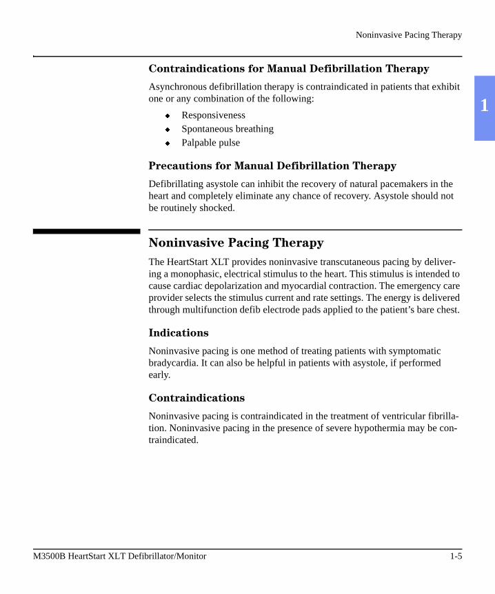
Noninvasive Pacing Therapy
The HeartStart XLT provides noninvasive transcutaneous pacing by deliver-ing a monophasic, electrical stimulus to the heart. This stimulus is intended to cause cardiac depolarization and myocardial contraction. The emergency care provider selects the stimulus current and rate settings. The energy is delivered through multifunction defib electrode pads applied to the patient’s bare chest.
Indications
Noninvasive pacing is one method of treating patients with symptomatic bradycardia. It can also be helpful in patients with asystole, if performed early.
Contraindications
Noninvasive pacing is contraindicated in the treatment of ventricular fibrilla-tion. Noninvasive pacing in the presence of severe hypothermia may be con-traindicated.
M3500B HeartStart XLT Defibrillator/Monitor 1-5

SpO2 Monitoring
SpO2 Monitoring
A pulse oximeter is a noninvasive device that indicates the oxygen saturation (SpO2) of arterial blood. This measurement is obtained through a probe that directs red and near infrared light through arterial beds. Hemoglobin absorbs these lights differently when it is bound with oxygen. Pulse oximetry mea-sures this difference and translates the measurement into a saturation percent-age that is displayed as an SpO2 reading.
Indications
SpO2 monitoring is indicated for use when it is beneficial to assess a patient’s
oxygen saturation level.
Contraindications
None known.
NOTE Readings should be carefully considered in the presence of certain circum-stances. Inaccuracies may result from the use of pulse oximeters in the pres-ence of certain circumstances, such as hemoglobin saturated with compounds other than oxygen (such as carbon monoxide), hypothermia, hypovolemia, patient movement, nail polish and excessive ambient light.
1-6 Introduction

Learning to Use the HeartStart XLT
1
Learning to Use the HeartStart XLT
The HeartStart XLT comes with:
� Using the HeartStart XLT Defibrillator/Monitor, a videotape, and� About Sealed Lead Acid Batteries, an application note on battery
maintenance.
For additional training materials, please visit our website at:
www.medical.philips.com/cms.
Safety Considerations
General warnings and cautions that apply to use of the HeartStart XLT are provided in Chapter 13. Additional warnings and cautions specific to a partic-ular feature are provided in the appropriate section of this guide.
M3500B HeartStart XLT Defibrillator/Monitor 1-7


2 Getting Started
2
Your HeartStart XLT is shipped to you in its carrying case with most of the accessories in their compartments. All you need to do before getting started is:� connect cables,� connect to power, and� insert the Data Card (if desired).
This chapter will acquaint you with the HeartStart XLT and then guide you through these activities.
NOTE To connect cables to the HeartStart XLT or to arrange accessories in the carry-ing case, refer to “Setting Up and Configuring the HeartStart XLT” in Chapter 10.
Getting AcquaintedThis section shows the HeartStart XLT controls/buttons, connections, and dis-play layout. An overview of control functions is also provided.
NOTE If your HeartStart XLT does not have the SpO2 or Pacing option, disregard these controls and the related information described in this section.
M3500B HeartStart XLT Defibrillator/Monitor 2-1

Getting Acquainted
Basic Orientation
The figure below shows the general layout of the controls, where the patient cables connect, and where to insert the battery and Data Card.
Figure 2-1 Basic Orientation
Audiovisual Controls ECG
Connector
SpO2
Connector
Manual Mode Controls
Battery
Ambient Light Sensor
PadsConnector
Off On
Printer
Print Controls
Monitoring Controls
AC Power Module Connector
Data Card
Defibrillation ControlsSpeaker
2-2 Getting Started

Getting Acquainted
2
- Powers on the HeartStart XLT.
- Powers off the HeartStart XLT.
Defibrillation Controls - softkeys that perform the defibrillation function displayed in the softkey label above each button; control both AED and Man-ual Mode defibrillation.
Manual Mode Controls - provide access to Manual Mode and control of syn-chronized cardioversion and pacing (if the option is present).
Audiovisual Controls:
Adjusts the display contrast.
Adjusts the size of the ECG waveform displayed, printed, and stored. Pressing and simultaneously generates a 1 mV calibration pulse.
Adjusts the volume of voice prompts and the QRS beeper.
Monitoring Controls - softkeys that perform the monitoring function dis-played in the softkey label below each button; control heart rate and SpO2 alarms and select the ECG source to monitor.
Print Controls - perform the function shown above each button. The print controls from left to right are:
PrintStrip
Prints ECG data, defibrillation events, and marked events real-time or with a 6 second delay (as configured). Press to start print-ing; press again to stop printing.
PrintSummary
Prints the Event Summary. (See “Storing, Retrieving & Printing” for more information.) Printing may be stopped by pressing the
or button.
MarkEvent
Inserts a time-stamped annotation in the Event Summary. May be configured to print an annotated ECG strip when pressed.
PrintSummary
PrintStrip
M3500B HeartStart XLT Defibrillator/Monitor 2-3

Getting Acquainted
Manual Mode Controls
The figure below shows the Manual Mode controls. These controls are accessed by lifting the door labeled "Manual."
Figure 2-2 Manual Mode Controls
NOTE Synchronized cardioversion and pacing controls only function when Manual Mode is enabled.
Manual
Sync
Pacer
Rate
StartStop Mode
Output
LEDs indicating the function is active (green light) or inactive (no light)
2-4 Getting Started

Getting Acquainted
2
Display Layout
The following figures show the layout of the display in:
� AED Mode, with ECG and SpO2 monitoring capabilities disabled.
� AED Mode, with ECG and SpO2 monitoring capabilities enabled.
� Manual Mode.
NOTE ECG and SpO2 monitoring capabilities for AED Mode may be enabled and disabled independently in the configuration.
Toggles between Manual Mode and AED Mode. Manual Mode is enabled when the green LED next to the key is lit. A password may be required for Manual Mode entry.
Enables synchronized cardioversion when first pressed, as indicated by the green LED; disables synchronized cardio-version when pressed again.
Activates the pacing function buttons (as indicated by the green LED), allowing you to use the buttons below to define pacing rate, mode, and current output. Also turns off the Pacer when pressed a second time.
Adjusts the pacing rate.
Delivers pacer pulses when first pressed; stops pacing when pressed again.
Selects Demand or Fixed Mode for pacing.
Adjusts the current output for pacing.
Manual
Sync
Pacer
Rate
StartStop
Mode
Output
M3500B HeartStart XLT Defibrillator/Monitor 2-5
Getting Acquainted
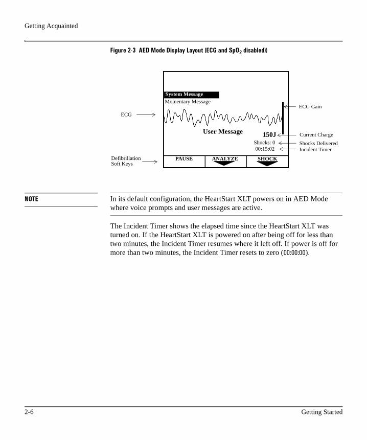
Figure 2-3 AED Mode Display Layout (ECG and SpO2 disabled)�
NOTE In its default configuration, the HeartStart XLT powers on in AED Mode where voice prompts and user messages are active.
The Incident Timer shows the elapsed time since the HeartStart XLT was turned on. If the HeartStart XLT is powered on after being off for less than two minutes, the Incident Timer resumes where it left off. If power is off for more than two minutes, the Incident Timer resets to zero (�� �� ��).
ANALYZEPAUSE
00:15:02Shocks: 0
User Message
SHOCK
150J
ECG
Current Charge
Shocks DeliveredIncident Timer
System Message Momentary Message
ECG Gain
DefibrillationSoft Keys
2-6 Getting Started

Getting Acquainted
2
Figure 2-4 AED Mode Display Layout (ECG and SpO2 Enabled)
User messages accompany voice prompts to guide you through the defibrilla-tion process.
System and Momentary Messages:
� alert you to conditions that may require you to take action,� provide status information, or� offer recommendations.
A System Message remains on the display until the condition that generated the message no longer exists. A Momentary Message is temporary and appears on the display for only a few seconds. A list of messages is provided in Chapter 12.
HR ALARM LEADSELECT SPO2
PAUSE ANALYZE SHOCK
Shocks: 000:15:02150J
114J
132 86PR 130 System Message
Momentary Message
Lead II
SpO2 value
SpO2 alarmPleth BarPulse Rate
Heart Rate
ECG
Selected Energy
DefibrillationSoft Keys
LeadDisplayed
HR Alarm
Current Charge
Shocks DeliveredIncident Timer
User Message
M3500B HeartStart XLT Defibrillator/Monitor 2-7

Getting Acquainted
Figure 2-5 Manual Mode Display Layout
LCD Backlight
Under normal operation, the HeartStart XLT reads the ambient light and turns on the LCD back light when low light conditions exist. To turn on the back
light at other times, press and on simultaneously. To return to
normal operation, press the same keys again. The back light also returns to normal operation each time you turn the HeartStart XLT on.
HR ALARM LEADSELECT SPO2
ENERGYSELECT
CHARGE SHOCK
Shocks: 000:15:02150J
114J
132 86PR 130 System Message
Momentary Message
Lead II
SpO2 value
SpO2 alarmPleth BarPulse Rate
Heart Rate
ECG
Selected Energy
Current Charge
Shocks DeliveredIncident Timer
LeadDisplayed
HR Alarm
Defibrillation Softkeys
2-8 Getting Started
Connecting to Power
2
Connecting to Power
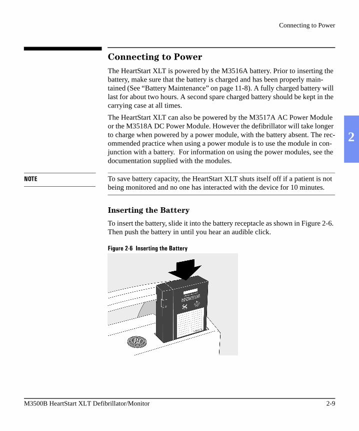
The HeartStart XLT is powered by the M3516A battery. Prior to inserting the battery, make sure that the battery is charged and has been properly main-tained (See “Battery Maintenance” on page 11-8). A fully charged battery will last for about two hours. A second spare charged battery should be kept in the carrying case at all times.
The HeartStart XLT can also be powered by the M3517A AC Power Module or the M3518A DC Power Module. However the defibrillator will take longer to charge when powered by a power module, with the battery absent. The rec-ommended practice when using a power module is to use the module in con-junction with a battery. For information on using the power modules, see the documentation supplied with the modules.
NOTE To save battery capacity, the HeartStart XLT shuts itself off if a patient is not being monitored and no one has interacted with the device for 10 minutes.
Inserting the Battery
To insert the battery, slide it into the battery receptacle as shown in Figure 2-6. Then push the battery in until you hear an audible click.
Figure 2-6 Inserting the Battery
M3500B HeartStart XLT Defibrillator/Monitor 2-9

Connecting to Power
Removing the Battery
Before removing the battery, make sure the HeartStart XLT is powered off. Then, to remove the battery, press the black battery eject button and pull the battery out, as shown in Figure 2-7.
Figure 2-7 Removing the Battery
Low Battery Warning
The message ��������� is displayed on the HeartStart XLT when the battery is low and needs recharging. This message indicates that the battery has suffi-cient remaining capacity to provide only about ten minutes of monitoring time and six shocks before the HeartStart XLT shuts off. Replace the battery as soon as possible.
If the power is off for less than 2 minutes, while you change the battery, the HeartStart XLT assumes that you are continuing to treat the same patient. It continues to store data on the Data Card and append events to the existing Event Summary. Alarms set prior to the power loss remain active.
If power remains off for more than 2 minutes, the HeartStart XLT assumes you are treating a different patient and assigns a new incident number. A new Event Summary begins with the next event.
2-10 Getting Started

Using a Data Card
2
Using a Data Card
Use of a Data Card is optional; the defibrillator will power up without a Data Card inserted. If you would like to collect patient information on a Data Card, the card must be inserted into the HeartStart XLT before the device is turned on.
CAUTION Inserting or removing the data card while the defibrillator is on can corrupt the Data Card and prevent the unit from powering on again. If this occurs, see Table 12-3, Troubleshooting Tips.
The recommended practice is to use one Data Card per patient. Once a Data Card fills, recording stops; a second Data Card may not be inserted for the current incident, because the device will only allow the use of one Data Card per incident. Data Cards hold up to two hours of patient information.
Multiple incidents can be recorded on a single Data Card. Each incident is assigned a unique incident number.
Patient data from a Philips M3510A Data Card may be downloaded to a HeartStart Event Review Data Management system. HeartStart Event Review also allows you to erase patient data from a Data Card, allowing the card to be reused for another patient.
It’s recommended that you use a designated Data Card to configure one or more defibrillators/monitors.
CAUTION Use only the M3510A Data Card. These cards are specifically formatted to work with your Philips defibrillator. Generic cards, or other types of cards (such as modems) will not work, and may cause the defibrillator tomalfunction.
M3500B HeartStart XLT Defibrillator/Monitor 2-11

Using a Data Card
Inserting a Data Card
To insert a Data Card:
1. Make sure the HeartStart XLT is powered off.2. Press up on the release latch to open the door to the Data Card compart-
ment.3. If a Data Card is already in the compartment, press the black button inside
the compartment to eject the card (see Figure 2-8). Then pull the card out.
4. With the yellow label facing up and the pointing towards the Heart-Start XLT, slide the Data Card into the compartment.
5. Close the Data Card compartment door. Make sure that you hear a click, indicating that the door is latched shut.
Figure 2-8 Inserting a Data Card
Eject
2-12 Getting Started

Using a Data Card
2
Removing a Data Card
To remove the Data Card:
1. Make sure the HeartStart XLT is powered off, (wait 2 seconds).2. Press the black eject button (see Figure 2-8).3. Pull the Data Card from the compartment.
M3500B HeartStart XLT Defibrillator/Monitor 2-13

3 Defibrillating in AED Mode
3
The HeartStart XLT’s AED Mode is designed to guide you through standard treatment algorithms for cardiac arrest, including those provided by the Amer-ican Heart Association and the European Resuscitation Council. Configura-tion choices allow you to customize AED Mode to better follow a specific treatment algorithm and to meet the unique needs of your life-saving team.
This chapter describes how to use the HeartStart XLT to defibrillate in AED Mode. It explains the prompts that guide you through the defibrillation pro-cess and describes how prompts vary depending upon the condition of the patient and the configuration of your device.
For information on printing, storing, and retrieving patient information acquired in AED Mode, see Chapter 9.
M3500B HeartStart XLT Defibrillator/Monitor 3-1

Figure 3-1 AED Mode Overview
If Patient is:
� Unresponsive� Not Breathing� Pulseless
Attach Pads
Insert Data Card(Optional)
Press On
If Instructed,
Press �������
ShockAdvised
Check Patientat completion of shock series
within a shock seriesNo Pulse Pulse
Ventilate
No ShockAdvised
Press
Do CPR�����
if Rhythm Monitoring on
Press �����
3-2 Defibrillating in AED Mode

Overview
3
Overview
An overview of the AED Mode defibrillation process is shown in Figure 3-1.
The process begins only after you have:
� assessed that the patient is unresponsive, not breathing, and pulseless, and
� prepared for defibrillation by attaching pads and inserting a Data Card (if desired).
Then you are ready to turn the HeartStart XLT on. The defibrillation process is dependent upon the configuration of your HeartStart XLT, as described in the following paragraphs.
Defibrillation (with the default configuration)
In its default configuration, the defibrillation process is:
Press the On button.
The HeartStart XLT checks to see if the pads patient cable and multi-function defib electrode pads are properly connected. If either con-nection is compromised, you are prompted to fix the problem.
Analysis begins automatically - there is no need to press .
Once analysis is complete, the HeartStart XLT tells you ������� !"# or ���������� !"# .
If a shock is advised, press .
After the first shock is delivered, the HeartStart XLT automatically begins analyzing the ECG and the process repeats until a shock series is complete or no shock is advised. At this point, you are prompted to check the patient.
�������
�����
M3500B HeartStart XLT Defibrillator/Monitor 3-3

Overview
Defibrillation (with a modified configuration)
Chapter 10 describes, in detail, the configurable parameters for AED Mode. Three parameters significantly impact the defibrillation process. They are:
Device Initiated Analysis - initiates ECG analysis when the HeartStart XLT is first turned on. The default configuration setting is On. If you choose to set this parameter to ���, you need to press to initiate analysis in step 2 of the defibrillation process.
Automatic Re-analysis - initiates ECG analysis in between shocks within a shock series. The default configuration setting is �$. If you choose to set this parameter to ���, you need to press to initiate analysis in between shocks within a shock series (i.e. after the first and second shock of a three shock series).
Rhythm Monitoring - monitors the ECG for potentially shockable rhythms when the HeartStart XLT is not analyzing, defibrillating, or paused. The default setting is �$%�If you choose to set this parameter to ���, the HeartStart XLT will not look for potentially shockable rhythms during these idle times. Idle times also include:
� power on, when Device Initiated Analysis is off.� in between shocks within a shock series, when Auto Re-analysis is
off.
If Rhythm Monitoring is off, you need to observe the patient during idle times and determine when to press .
The following sections describe the defibrillation process in detail. They also describe what happens at the completion of a shock series and if a shockable rhythm is not detected.
�������
�������
�������
3-4 Defibrillating in AED Mode

Preparation
3
Preparation
If the patient is:
� unresponsive� not breathing� pulseless
Then:
1. Apply multifunction defib electrode pads to the patient, as directed on the package. Use the anterior-anterior electrode placement.
2. Connect the pads to the pads patient cable, as shown in Figure 3-2.3. If needed, insert a Data Card (as described in “Using a Data Card” on 2-
11).
Figure 3-2 Connecting Pads to the Patient Cable
M3500B HeartStart XLT Defibrillator/Monitor 3-5

Defibrillating
Defibrillating
Follow the voice and screen prompts as they guide you through the following steps:
1. Press On.
In this first step of the defibrillation process, the HeartStart XLT checks to see if the pads patient cable and the pads are connected. If they are, it pro-ceeds to step 2.
If the pads patient cable is not properly attached, you are prompted to ��$&$����� #���'(.
Figure 3-3 Connect Pads Cable Display
Once the cable is connected, the HeartStart XLT checks to make sure the pads are making good contact with the patient’s skin. It does this by moni-toring the electrical impedance between the two pads.
ConnectPadsCable
Shocks: 000:00:02
3-6 Defibrillating in AED Mode
Defibrillating
3
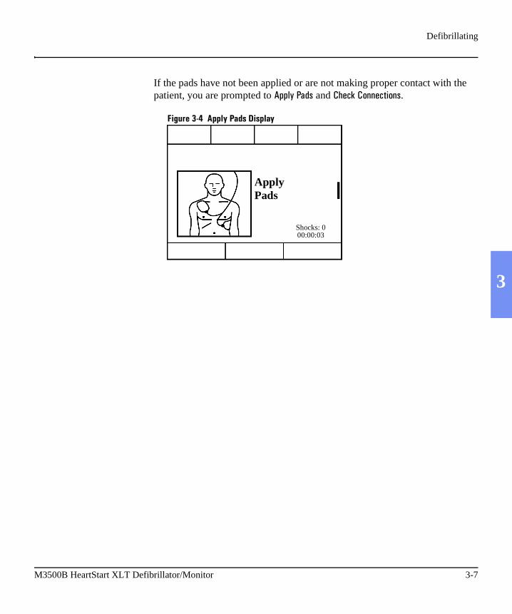
If the pads have not been applied or are not making proper contact with the patient, you are prompted to �))(��� # and �������$$��"�$#.
Figure 3-4 Apply Pads Display
ApplyPads
Shocks: 000:00:03
M3500B HeartStart XLT Defibrillator/Monitor 3-7

Defibrillating
2. If instructed, press .
If device-initiated analysis is off, the HeartStart XLT monitors the rhythm (provided Rhythm Monitoring is on) and prompts you to press if a potentially shockable rhythm is detected.
Figure 3-5 Press ANALYZE Display
NOTE If monitoring capabilities are enabled on your HeartStart XLT, your display will contain monitoring information not shown in the graphics in this section.
NOTE ECG Analysis is always performed through multifunction defib electrode pads. Analysis can not be performed through monitoring electrodes.
�������
�������
Shocks: 000:00:04
Check PatientIf No Pulse
Press ANALYZE
PAUSE ANALYZE
3-8 Defibrillating in AED Mode

Defibrillating
3
If device initiated analysis is on, you do not need to press ; ECG analysis begins automatically.
Figure 3-6 Analyzing Display
WARNING Handling or transporting the patient during ECG analysis can cause incorrect or delayed diagnosis.
If a shockable rhythm is detected, as indicated by the message ������� !"# , analysis stops and the XLT automatically charges to 150J. Charging is accom-panied by an intermittent charge tone.
Figure 3-7 Charging Display
�������
Shocks: 000:00:08
AnalyzingDo Not Touch Patient
STOPANALYSIS
Shocks: 000:00:10
Charging to 150J97J
M3500B HeartStart XLT Defibrillator/Monitor 3-9

Defibrillating
3. If shock advised, press .
Once charging is complete, the charge tone becomes continuous. Make sure no one is touching the patient or anything connected to the patient. Call out "Clear." Then press to deliver a shock to the patient.
Figure 3-8 Press SHOCK Display
WARNING Defibrillation current can cause operator or bystander injury. Do not touch the patient, or equipment connected to the patient, during defibrillation.
The defibrillator automatically disarms if you do not press in 30 seconds.
�����
�����
Shocks: 000:00:14
Stand Clear!Press SHOCK 150J
SHOCK
�����
3-10 Defibrillating in AED Mode

Defibrillating
3
Delivery of the shock is confirmed by the message ������*("!� and the shock counter is updated.
Figure 3-9 Shock Delivered Display
Automatic Re-analysis On
If Automatic Re-analysis is on, the HeartStart XLT analyzes the ECG fol-lowing delivery of the shock. You are prompted to press , if an addi-tional shock is advised. This cycle repeats until the rhythm converts or a shock series is complete. (A shock series may be configured to 2, 3, or 4 shocks.)
Automatic Re-analysis Off
If Automatic Re-analysis is off, the HeartStart XLT monitors the ECG for potentially shockable rhythms (provided Rhythm Monitoring is on) and prompts you to press if one is detected. You can initiate analysis, without being prompted, by pressing .
Shocks: 100:00:40
Shock Delivered
�����
�������
�������
M3500B HeartStart XLT Defibrillator/Monitor 3-11

Pausing for CPR
Pausing for CPR
At the completion of a shock series or when no shock is advised, the Heart-Start XLT prompts you to ��������"$�+�������,(#-. It allows eight seconds for you to check the pulse, then prompts you as follows:
Figure 3-10 Press Pause Display
If CPR is needed, press . While paused, the Pause Timer indicates the elapsed time and the total duration of the Pause state, in seconds. The Pause Timer is configurable to meet your local CPR protocol needs. Rhythm, SpO2 and heart rate monitoring alarms are suspended for the duration of the pause.
NOTE * This section describes how the Pause state functions using the default con-figuration. If your HeartStart XLT is configured to support the European Resuscitation Council Guidelines for Resuscitation, refer to the “ERC Proto-col” section on page 3-16 for details.
Shocks: 100:00:50
If NeededPress PAUSE
And Begin CPR
PAUSE ANALYZE
�����
3-12 Defibrillating in AED Mode

Pausing for CPR
3
Figure 3-11 Pause Display
The pause state ends when the Pause Timer reaches the preconfigured Pause state duration, or if you press or . At the completion of the pause state, the defibrillation process begins again. If instructed, press
.
If you do not press , the HeartStart XLT begins monitoring the ECG rhythm (provided Rhythm Monitoring is on).
You may initiate ECG analysis at any time by pressing .
Shocks: 300:01:40
Paused
RESUME ANALYZE
Timer: 21 / 60
Elapse TimeTotal Pause Duration
.���/� �������
�������
�����
�������
M3500B HeartStart XLT Defibrillator/Monitor 3-13
Monitoring Rhythm
Monitoring Rhythm
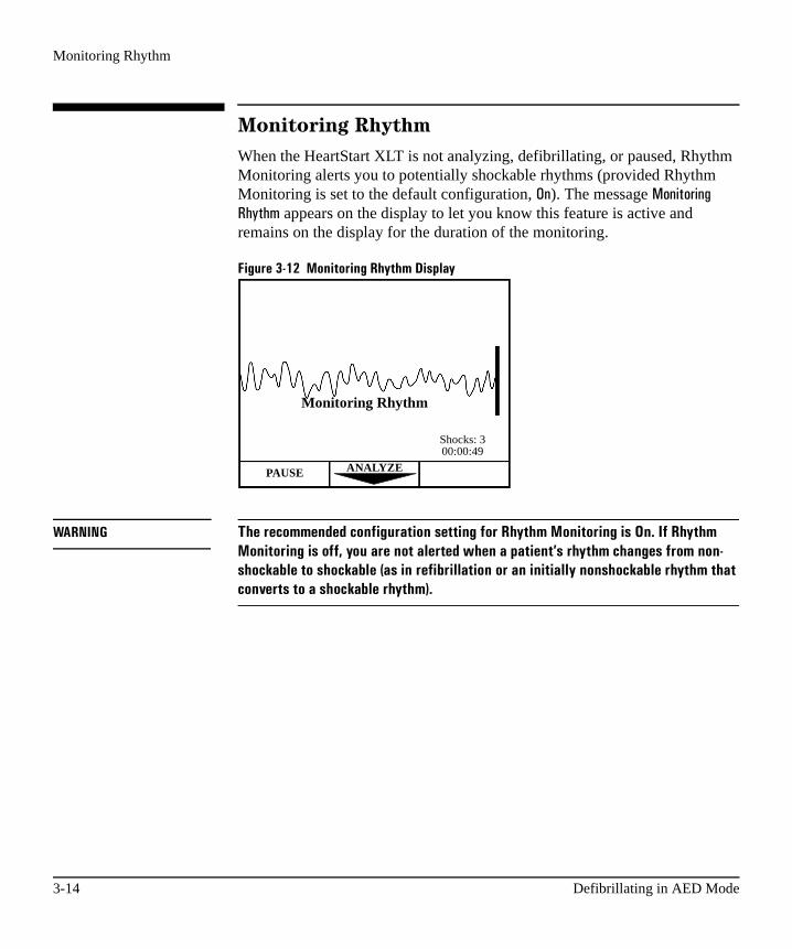
When the HeartStart XLT is not analyzing, defibrillating, or paused, Rhythm Monitoring alerts you to potentially shockable rhythms (provided Rhythm Monitoring is set to the default configuration, �$). The message /�$"���"$0�.���1 appears on the display to let you know this feature is active and remains on the display for the duration of the monitoring.
Figure 3-12 Monitoring Rhythm Display
WARNING The recommended configuration setting for Rhythm Monitoring is On. If Rhythm Monitoring is off, you are not alerted when a patient’s rhythm changes from non-shockable to shockable (as in refibrillation or an initially nonshockable rhythm that converts to a shockable rhythm).
Shocks: 300:00:49
Monitoring Rhythm
PAUSE ANALYZE
3-14 Defibrillating in AED Mode

Monitoring Rhythm
3
If Rhythm Monitoring detects a shockable rhythm, you are prompted as fol-lows:
Figure 3-13 Shockable Rhythm
This prompt is repeated periodically, as configured, until or is pressed. If you press , the defibrillation process starts again.
If you press , rhythm monitoring is suspended for the duration of the pause. is used when administering CPR, as noted earlier. It may also be useful when performing medical procedures or encountering artifact during patient transport. Active SpO2 and heart rate alarms are suspended during the pause duration, as well.
Press to restore rhythm monitoring. Active SpO2 and heart rate alarms are also restored.
Shocks: 300:00:55
Check PatientIf No Pulse
Press ANALYZE
PAUSE ANALYZE
������� �����
�������
�����
�����
.���/�
M3500B HeartStart XLT Defibrillator/Monitor 3-15
ERC Protocol
ERC Protocol
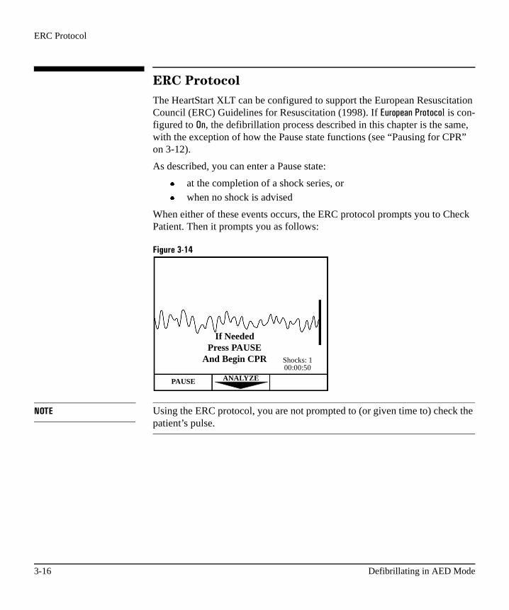
The HeartStart XLT can be configured to support the European Resuscitation Council (ERC) Guidelines for Resuscitation (1998). If �,��)�$��������l is con-figured to �$, the defibrillation process described in this chapter is the same, with the exception of how the Pause state functions (see “Pausing for CPR” on 3-12).
As described, you can enter a Pause state:
� at the completion of a shock series, or� when no shock is advised
When either of these events occurs, the ERC protocol prompts you to Check Patient. Then it prompts you as follows:
Figure 3-14
NOTE Using the ERC protocol, you are not prompted to (or given time to) check the patient’s pulse.
Shocks: 100:00:50
If NeededPress PAUSE
And Begin CPR
PAUSE ANALYZE
3-16 Defibrillating in AED Mode
ERC Protocol
3
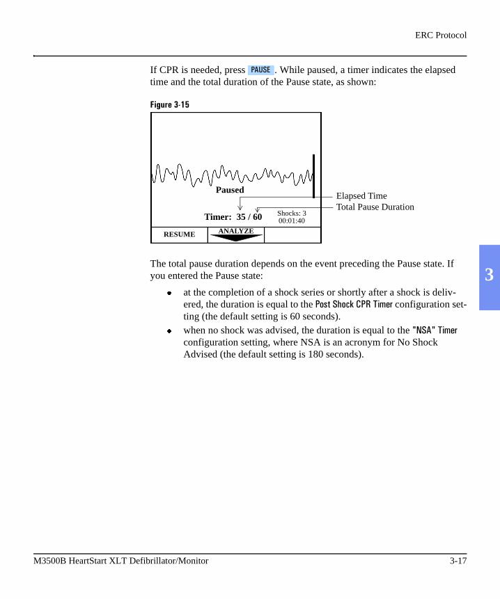
If CPR is needed, press . While paused, a timer indicates the elapsed time and the total duration of the Pause state, as shown:
Figure 3-15
The total pause duration depends on the event preceding the Pause state. If you entered the Pause state:
� at the completion of a shock series or shortly after a shock is deliv-ered, the duration is equal to the ��#����������.��"1� configuration set-ting (the default setting is 60 seconds).
� when no shock was advised, the duration is equal to the 2���2��"1� configuration setting, where NSA is an acronym for No Shock Advised (the default setting is 180 seconds).
�����
Shocks: 300:01:40
Paused
RESUME ANALYZE
Timer: 35 / 60
Elapsed TimeTotal Pause Duration
M3500B HeartStart XLT Defibrillator/Monitor 3-17

Troubleshooting
Troubleshooting
When the HeartStart XLT detects a problem, it provides display and/or voice prompts to guide you to resolution. The table below lists the prompts you may encounter in AED Mode, the cause, and the suggested corrective action. Prompts related to the battery and Data Card are discussed in Chapter 12.
Table 3-1 AED Mode Prompts
Prompt Possible Cause Corrective Action
Pads Off The multifunction defib electrode pads are not properly applied to the patient.
Check that the pads are applied to the patient, as directed on the pads’ package. Replace the pads if the prompt continues.
Pads Cable Off
The pads cable is not connected to the defibrillator.
Check that the defibrillation pads connector is locked in place.
Artifact Detected
� Patient motion interferes with analysis.
� Electrical sources are causing interference.
� Attempt to eliminate patient motion. Avoid analyzing during transport or while performing CPR.
� Move hand-held communication devices or other suspected devices away from the defibril-lator, when possible.
Shock Can-celled
Shock key not pressed within 30 seconds.
Press within 30 seconds of prompt.
No Shock Delivered
Pads are not properly connected to the patient.
Check pads connection.
Key Inactive
� The key pressed only functions in Manual Mode.
� The key pressed does not func-tion during analysis or charging.
� The key pressed does not func-tion while in a pause state.
� Access manual mode prior to pressing the key.
� Wait for analysis or charging to complete prior to pressing the key.
� Press prior to pressing
the key. .���/�
3-18 Defibrillating in AED Mode

4 Monitoring the ECG
4
The HeartStart XLT can be used for short or long-term ECG monitoring. The ECG monitoring function allows you to monitor through:
� multifunction defib electrode pads, or� 3- or 5-lead ECG monitoring electrodes, as configured.
When the HeartStart XLT is turned on, the ECG acquired through pads is shown on the display. ECG monitoring allows you to continue to monitor through the pads or to select a lead from an alternate ECG source (3- or 5-lead). ECG monitoring also displays the heart rate (HR) and allows you to set HR alarms.
ECG monitoring is always active in Manual Mode. In AED Mode, ECG mon-itoring is only active if �� ��(���is configured to on (the default is off).
A fully charged battery provides approximately 2.7 hours of continuous mon-itoring.
This chapter describes how to apply monitoring electrodes, select the lead to monitor, and set a heart rate (HR) alarm. To apply multifunction defib elec-trode pads, follow the directions on the pads packaging. For information on printing, storing, and retrieving patient information acquired while monitor-ing, see Chapter 9.
NOTE If you need to connect the ECG cable to the HeartStart XLT or configure the HeartStart XLT to use the optional 5-lead monitoring cable, see Chapter 10.
M3500B HeartStart XLT Defibrillator/Monitor 4-1
Applying Monitoring Electrodes
Applying Monitoring Electrodes
Proper application and placement of electrodes is essential for reliable moni-toring. Good contact between the electrode and the skin reduces the effects of motion artifact and signal interference.
To apply electrodes:
1. Identify the appropriate electrode sites. (See Figure 4-1.)
2. Shave the electrode sites or clip hair, if necessary.
3. Clean and abrade the skin at the electrode sites.
4. Dry the skin at the electrode sites.
5. Open a new package of M2202A Radio-Translucent Monitoring Elec-trodes; verify that the "Use Before" date has not passed.
6. Snap the lead wires onto the electrodes.
7. Apply the electrodes by peeling them, one at a time, from the protective backing and sticking them firmly to the patient’s skin. Press around the entire edge of each electrode to ensure that they are secure. Make sure the lead wires do not pull on the electrodes.
WARNING Be sure that the electrodes do not come in contact with other conductive materials, especially when connecting or disconnecting the electrodes to/from the patient.
NOTE If monitoring for long periods of time, new monitoring electrodes and multifunction defib electrode pads may need to be applied periodically. Refer to the manufacturer’s documentation for how often to replace the monitoring electrodes or defib pads.
4-2 Monitoring the ECG
Applying Monitoring Electrodes
4
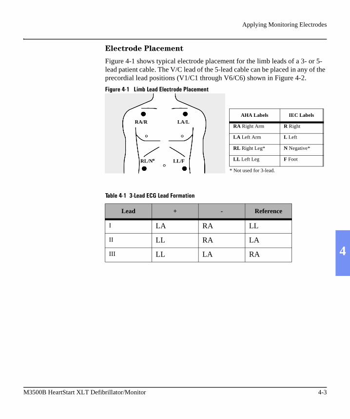
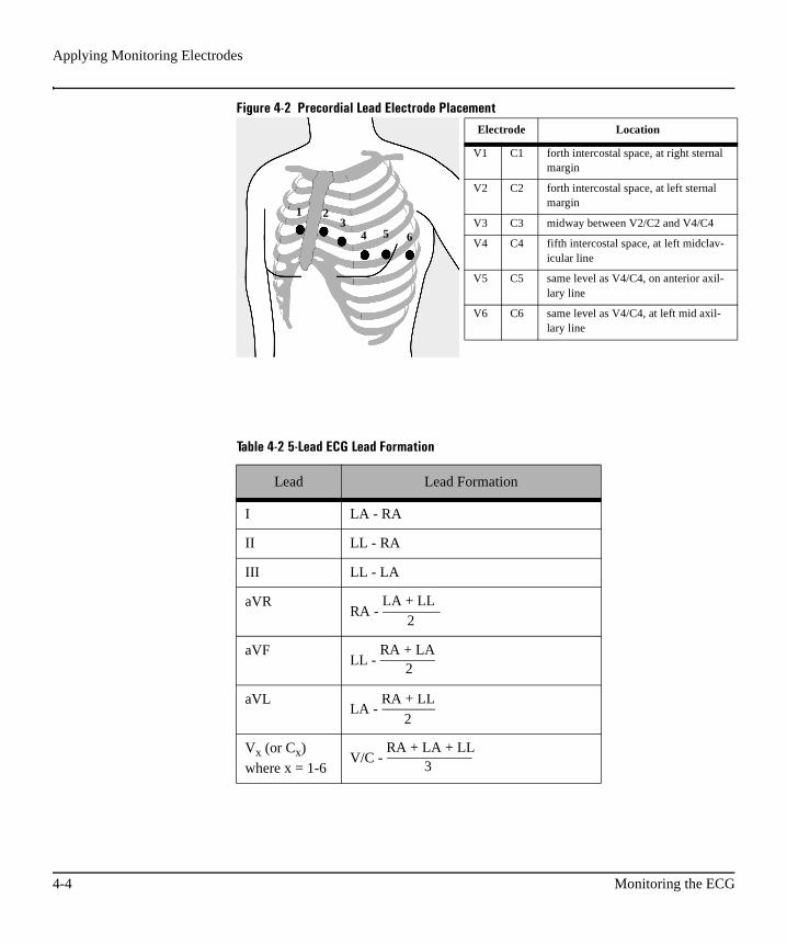
Electrode Placement
Figure 4-1 shows typical electrode placement for the limb leads of a 3- or 5-lead patient cable. The V/C lead of the 5-lead cable can be placed in any of the precordial lead positions (V1/C1 through V6/C6) shown in Figure 4-2.
Figure 4-1 Limb Lead Electrode Placement
Table 4-1 3-Lead ECG Lead Formation
Lead + - Reference
I LA RA LL
II LL RA LA
III LL LA RA
AHA Labels IEC Labels
RA Right Arm R Right
LA Left Arm L Left
RL Right Leg* N Negative*
LL Left Leg F Foot
RA/R LA/L
RL/N LL/F
* Not used for 3-lead.
*
M3500B HeartStart XLT Defibrillator/Monitor 4-3
Applying Monitoring Electrodes
Figure 4-2 Precordial Lead Electrode Placement
Table 4-2 5-Lead ECG Lead Formation
Lead Lead Formation
I LA - RA
II LL - RA
III LL - LA
aVRRA -
aVFLL -
aVLLA -
Vx (or Cx)
where x = 1-6V/C -
1 23
4 5 6
LA + LL2
RA + LA2
RA + LL
2
RA + LA + LL3
Electrode Location
V1 C1 forth intercostal space, at right sternal margin
V2 C2 forth intercostal space, at left sternal margin
V3 C3 midway between V2/C2 and V4/C4
V4 C4 fifth intercostal space, at left midclav-icular line
V5 C5 same level as V4/C4, on anterior axil-lary line
V6 C6 same level as V4/C4, at left mid axil-lary line
4-4 Monitoring the ECG

Selecting the Lead
4
Selecting the Lead
Available monitoring leads are dependent upon your device configuration:
To select a lead to monitor, cycle through the choices by pressing until the desired lead is displayed.
NOTE When V lead is selected, change to a different V lead by moving the electrode
to a new location rather than by pressing the softkey.
Figure 4-3 ECG Monitoring Display
If the desired lead is not connected or the electrodes are not making proper contact with the patient, the message �� #���� is displayed in the System Mes-sage Area and accompanied by a beep to alert you. A dashed line on the dis-play indicates that there is no ECG signal.
Table 4-3 Lead Select Choices
Lead Select Choices are:
If Configured for a:
Pads, Lead I, Lead II, Lead III 3-lead ECG cable
Pads, Lead I, Lead II, Lead III, aVR, aVL, aVF, V lead.
5-lead ECG cable
���*������
���*������
PAUSE
HR ALARM LEADSELECT
ANALYZE
Shocks: 300:00:49
Monitoring Rhythm
78 Lead II
M3500B HeartStart XLT Defibrillator/Monitor 4-5
Setting the Heart Rate Alarm
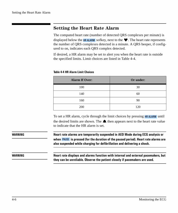
Setting the Heart Rate Alarm
The computed heart rate (number of detected QRS complexes per minute) is displayed below the sofkey, next to the . The heart rate represents the number of QRS complexes detected in a minute. A QRS beeper, if config-ured to on, indicates each QRS complex detected.
If desired, a HR alarm may be set to alert you when the heart rate is outside the specified limits. Limit choices are listed in Table 4-4.
To set a HR alarm, cycle through the limit choices by pressing until
the desired limits are shown. The then appears next to the heart rate value to indicate that the HR alarm is set.
WARNING Heart rate alarms are temporarily suspended in AED Mode during ECG analysis or when is pressed (for the duration of the paused period). Heart rate alarms are also suspended while charging for defibrillation and delivering a shock.
WARNING Heart rate displays and alarms function with internal and external pacemakers, but they can be unreliable. Observe the patient closely if pacemakers are used.
Table 4-4 HR Alarm Limit Choices
Alarm If Over: Or under:
100 30
140 60
160 90
200 120
�.����./
�.����./
�����
4-6 Monitoring the ECG

Disabling the HR Alarm
4
Disabling the HR Alarm
If the heart rate is outside the HR alarm limits, an alarm sounds. To disable the
alarm, press . appears to indicate that the alarm is disabled.
Adjusting the ECG Size
To increase or decrease the size of the ECG, press or on the gain con-
trol, .
Troubleshooting
Table 4-5 provides troubleshooting tips for ECG Monitoring.
�.����./
Table 4-5 Troubleshooting Tips
Situation Cause Solution
�� #�����message�
or
dashed line (------)
� The monitoring elec-trodes are not applied or are not making proper contact with the patient.
� The monitoring cable is not connected.
� Check that the monitoring electrodes are properly applied.
� Check that the monitoring cable is properly con-nected.
�� #�����message� � The pads are not mak-ing proper contact with the patient.
� Check that the pads are properly applied.
M3500B HeartStart XLT Defibrillator/Monitor 4-7

Troubleshooting
Poor ECG signal quality
� The monitoring elec-trodes are not making proper contact with the patient.
� The monitoring elec-trodes are outdated or dried-out.
� Radio frequency inter-ference (RFI) is causing artifact.
� Check that the monitoring electrodes are properly applied. If necessary, pre-pare the patient’s skin and apply new electrodes.
� Check the date code on the electrodes. Do not open the electrode pack-age until immediately prior to use.
� Relocate or turn off equip-ment that may be causing RFI.
QRS beeper inau-dible or beeps do not occur with each QRS com-plex.
� The QRS beeper is con-figured to Off.
� The amplitude of the QRS complex is too small to detect.
� Check that the QRS beeper is configured to On.
� Adjust the volume.� Adjust the size of the
ECG.
Table 4-5 Troubleshooting Tips (Continued)
Situation Cause Solution
4-8 Monitoring the ECG

5 Monitoring SpO2
5
Pulse oximetry is a noninvasive method of continuously measuring oxygen saturation (SpO2) in arterial blood. The resultant SpO2 reading indicates the percentage of hemoglobin molecules in the arterial blood which are saturated with oxygen. SpO2 monitoring is one of the tools available to assist in assess-ing a patient’s cardiac and respiratory systems. This chapter explains how pulse oximetry works and describes how to use the HeartStart XLT to monitor SpO2.
SpO2 monitoring is always available in Manual Mode (if the option is pur-chased). In AED Mode, SpO2 monitoring is only available if SpO2 is config-ured to �$.
For information on printing, storing, and retrieving patient information acquired while monitoring, see Chapter 9.
WARNING Do not rely solely on SpO2 readings; assess the patient at all times. SpO2 readings may be inaccurate in the presence of significant levels of carboxyhemoglobin or methemoglobin, in patients with restricted blood flow to the extremities (such as those in severe shock or hypothermia), or in the presence of excessive motion.
M3500B HeartStart XLT Defibrillator/Monitor 5-1

Understanding Pulse Oximetry
Understanding Pulse Oximetry
A pulse oximetry sensor sends light through patient tissue to a receiver on the other side of the sensor. As Figure 5-1 shows, light emitting diodes transmit red and infrared light through peripheral areas of the body, such as a finger.
Figure 5-1 Pulse Oximetry Sensor
A photodetector positioned opposite the light emitting diodes compares light absorption before and after pulsation. The amount of light getting through reflects the blood flow in the arterioles. This measurement of light absorption during pulsation is translated into an oxygen saturation percentage and an SpO2 value is displayed.
For accurate SpO2 measurements, the following conditions must apply:
� The patient must have perfusion in that extremity.� The light emitter and the photodetector must be directly opposite each
other.� All of the light from the emitter must pass through the patient’s tissue.� The sensor site should be free of vibration and excessive motion.� Power cables should be kept away from the sensor cable and connec-
tor.
LED
Photodetector
5-2 Monitoring SpO2

Selecting a Sensor
5
Selecting a Sensor
Table 5-1 shows the SpO2 sensors that may be used with the HeartStart XLT.
NOTE To use Nellcor sensors, you must connect the M1943A Nellcor Adaptor patient cable to the HeartStart XLT. (See “Connecting the SpO2 Patient Cable” on page 10-5.)
Table 5-1 Approved Sensors
Sensor Type Patient Patient Size Ideal Site
M1191A Reusable Adult > 50 kg Finger
M1192A Reusable Small adultPediatric
15-50 kg Finger
M1194A Reusable PediatricAdult
> 40 kg Fleshy part of ear
M1903A/B(Nellcor D-20)
Disposable Pediatric 10-50 kg Toe/Finger
M1904A/B(Nellcor D-25)
Disposable Adult > 30 kg Finger
M1906A(Nellcor P/I)
Semi-reus-able
PediatricInfant
3-40 kg Finger/Toe
M1907A(Nellcor A/N)
Semi-reus-able
Neonate < 3 kg Foot/Hand
Adult > 40 kg Finger
M3500B HeartStart XLT Defibrillator/Monitor 5-3

Selecting a Sensor
The most important factor when selecting a sensor is the position of the light emitting diodes in relation to the photodetector; when a sensor is applied, the diodes and the photodetector must be opposite each other. Sensors are designed for patients within a specific weight range and for specific sites. Be sure to:
� Select a sensor appropriate for the patient’s weight.� Select a sensor site with adequate perfusion.� Avoid application to sites with edematous tissue.
Reusable Sensors
Reusable sensors may be reused on different patients after they have been cleaned and disinfected (see the manufacturer’s instructions supplied with the sensor).
Disposable Sensors
Disposable sensors should be used only once and then discarded. They can be relocated to a different application site on the patient if the first location does not give the desired results. Disposable sensors must not be reused on differ-ent patients.
Semi-disposable Sensors
Semi-disposable sensors can be reused, but the adhesive wrap must be dis-carded after each use. Semi-disposable sensors are recommended for single-patient use only.
5-4 Monitoring SpO2
Applying the Sensor
5
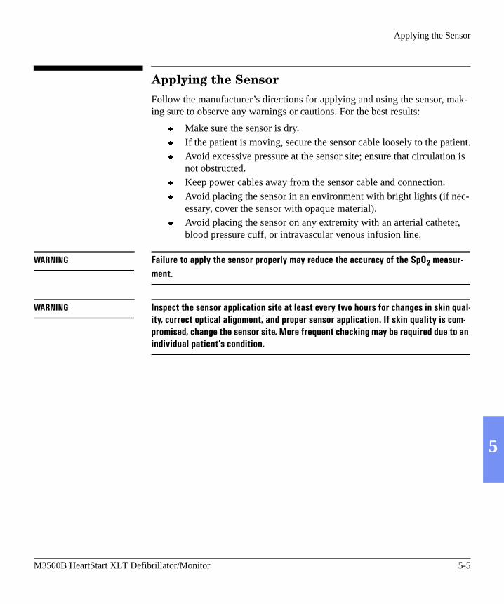
Applying the Sensor
Follow the manufacturer’s directions for applying and using the sensor, mak-ing sure to observe any warnings or cautions. For the best results:
� Make sure the sensor is dry.� If the patient is moving, secure the sensor cable loosely to the patient.� Avoid excessive pressure at the sensor site; ensure that circulation is
not obstructed.� Keep power cables away from the sensor cable and connection.� Avoid placing the sensor in an environment with bright lights (if nec-
essary, cover the sensor with opaque material).� Avoid placing the sensor on any extremity with an arterial catheter,
blood pressure cuff, or intravascular venous infusion line.
WARNING Failure to apply the sensor properly may reduce the accuracy of the SpO2 measur-ment.
WARNING Inspect the sensor application site at least every two hours for changes in skin qual-ity, correct optical alignment, and proper sensor application. If skin quality is com-promised, change the sensor site. More frequent checking may be required due to an individual patient’s condition.
M3500B HeartStart XLT Defibrillator/Monitor 5-5

Connecting the Sensor Cable
Connecting the Sensor Cable
To connect a sensor cable:
1. Hold the connector with the flat side up so that the part number is visible.2. Insert the connector into the receptacle and push until the blue portion of
the connector is no longer visible.
Figure 5-2 Connecting the Sensor Cable
5-6 Monitoring SpO2

Monitoring
5
Monitoring
To monitor SpO2:
1. If the HeartStart XLT is not on, press On.2. Apply the appropriate sensor to the patient.3. Make sure the sensor cable is connected to the HeartStart XLT.
4. Press to turn on SpO2 monitoring.
A dashed line (---) is displayed under , while the oxygen saturation is measured and an SpO2 value is calculated. In a few seconds the SpO2 value is displayed in place of the dashed line. As the patient’s oxygen saturation changes, the SpO2 value is updated continuously.
Figure 5-3 SpO2 Monitoring Display
To the right of the SpO2 value, a pleth bar and SpO2 alarm indicator are dis-played. The pleth bar should be observed for fluctuation. It is an indication of pulsation detected by the sensor. The pleth bar should not be used as the sole indicator of pulsation because it can be influenced by movement and artifact.
The symbol indicates no alarm is set.
Below the SpO2 value is the pulse rate derived from the pulse oximetry.
�)��
�)��
PAUSE
HR ALARM LEADSELECT
ANALYZE
Shocks: 300:00:49
Monitoring Rhythm
78 Pads
SpO2
98PR 62
M3500B HeartStart XLT Defibrillator/Monitor 5-7

Setting Alarms
Setting Alarms
An alarm may be set to alert you if the SpO2 value falls below a specified
lower limit. Lower limit alarm choices are (no alarm), 90, 85, or 80. Press repeatedly to cycle through the choices. Stop when the desired choice is
displayed. A appears in three seconds, indicating that the selected alarm is active. To review the alarm limit, press .
WARNING SpO2 alarms are temporarily suspended in AED Mode during ECG analysis or when
is pressed (for the duration of the paused period). SpO2 alarms are also sus-pended while charging for defibrillation and delivering a shock.
Responding to an Alarm
When the SpO2 value falls below the alarm limit, a continuous tone alerts you and the SpO2 value is displayed in inverse video.
Figure 5-4 SpO2 Alarm Triggered
Press to turn off the alarm. Refer to “Setting Alarms” if subsequent alarms are desired.
�)��
�)��
�����
PAUSE
HR ALARM LEADSELECT
ANALYZE
Shocks: 300:00:49
Monitoring Rhythm
78 Pads
SpO2
87PR 80
�)��
5-8 Monitoring SpO2

Discontinuing SpO2 Monitoring
5
Discontinuing SpO2 Monitoring
To shut off SpO2 monitoring, press repeatedly until nothing appears
below the softkey.
Figure 5-5 SpO2 Monitoring Off
Caring for Sensors
Refer to the manufacturers instructions for care and cleaning of sensors. To get the best results from your SpO2 reusable sensors, always handle the sensor and cable with care and protect them from sharp objects. The sensor sleeve houses a sensitive electronic device that can be damaged. Harsh treatment of sensors will drastically reduce their lifetime.
WARNING Do not use a damaged sensor or one with exposed electrical circuits.
�)���)��
PAUSE
HR ALARM LEADSELECT
ANALYZE
Shocks: 300:00:49
Monitoring Rhythm
78 Pads
SpO2
M3500B HeartStart XLT Defibrillator/Monitor 5-9
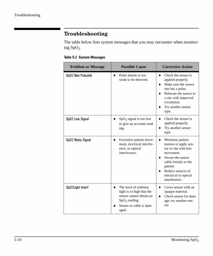
Troubleshooting
Troubleshooting
The table below lists system messages that you may encounter when monitor-ing SpO2.
Table 5-2 System Messages
Problem or Message Possible Cause Corrective Action
�)�3���$��,(#��"( � Pulse absent or too weak to be detected.
� Check the sensor is applied properly.
� Make sure the sensor site has a pulse.
� Relocate the sensor to a site with improved circulation.
� Try another sensor type.
�)�3������"0$�( � SpO2 signal is too low
to give an accurate read-ing.
� Check the sensor is applied properly.
� Try another sensor type.
�)�3���"#��"0$�( � Excessive patient move-ment, electrical interfer-ence, or optical interference.
� Minimize patient motion or apply sen-sor to site with less movement.
� Secure the sensor cable loosely to the patient.
� Reduce sources of electrical or optical interference.
�)�3�"0���4$��� � The level of ambient light is so high that the sensor cannot obtain an SpO2 reading.
� Sensor or cable is dam-aged.
� Cover sensor with an opaque material.
� Check sensor for dam-age; try another sen-sor.
5-10 Monitoring SpO2

Troubleshooting
5
�)�3��'(���� � The SpO2 cable is not
connected to the device.
� Attach the cable to the HeartStart XLT.
�)�3�
�$#���5�"(� � The transducer is bro-ken.
� Apply a new trans-ducer.
�)�35�"(,�� � There is a hardware fail-ure in the SpO2 sub-
system.
� Remove device from active use and call for service.
Table 5-2 System Messages (Continued)
Problem or Message Possible Cause Corrective Action
M3500B HeartStart XLT Defibrillator/Monitor 5-11


6
6 Defibrillating in Manual Mode
In Manual Mode you assess the ECG, decide if defibrillation is indicated, select the discharge energy level, and deliver the shock. The defibrillation process is under your control. There are no voice prompts, however, system and momentary messages provide relevant information throughout the pro-cess. It is important to be attentive to these messages.
This chapter describes how to access Manual Mode and use it for defibrilla-tion. For Manual Mode features such as synchronized cardioversion and pac-ing, see the “Performing Synchronized Cardioversion” and “Pacing” chapters.
For information on printing, storing, and retrieving patient information acquired in Manual Mode, see Chapter 9.
M3500B HeartStart XLT Defibrillator/Monitor 6-1

Enabling Manual Mode
Enabling Manual Mode
From AED Mode, press to enable Manual Mode. If prompted, use the softkeys above the display to enter the password.
Figure 6-1: Manual Password Display
To return to AED Mode, without entering a password, press .
Once Manual Mode is enabled, the green LED next to is lit.
In its default configuration, the HeartStart XLT powers on into AED Mode. If you prefer, you can configure it to power on into Manual Mode. You have the option to require users to enter a password in order to enable Manual Mode from AED Mode. (See “Configuring the HeartStart XLT” on page 10-7.
WARNING Use of a password for Manual Mode is recommended as a safety measure to deter untrained personnel from entering Manual Mode.
Manual
1 2 3 4
EXITPASSWORD
Enter Password
Shocks: 300:00:49
��4�����6�.*
Manual
6-2 Defibrillating in Manual Mode

Preparation
6
Preparation
In preparation for defibrillation:
1. Apply multifunction defib electrode pads as directed on the package. Use either the anterior-anterior or anterior-posterior electrode placement, as appropriate.
2. Connect the pads to the pads patient cable, as shown in Figure 6-2.3. If needed, insert a Data Card (as described in “Using a Data Card” on 2-
11).4. Press On.5. Enter Manual Mode, if AED Mode is active.
Figure 6-2 Connecting Pads to the Patient Cable
NOTE Defibrillation is always performed through pads. However, during defibrilla-tion, you may choose to monitor ECG using an alternate ECG source (3- or 5-lead monitoring electrodes).
M3500B HeartStart XLT Defibrillator/Monitor 6-3

Defibrillating
Defibrillating
The defibrillation process is as follows:
1. Select Energy
The default energy setting is 150 joules. To change the energy setting,
press repeatedly to cycle through the energy level choices. Stop
when the desired energy is displayed. The choices are 5, 10, 25, 50, 70, 100, 150, or 200 joules.
Figure 6-3 Energy Select Display
2. Charge
Press .
As the defibrillator charges, the current charge is displayed above the shock counter. A charging tone beeps until the desired energy level is reached, at which point you’ll hear a continuous charge tone.
���.7�������
ENERGYSELECT
HR ALARM LEADSELECT
CHARGE
Shocks:000:00:8
78 Pads
SpO2
150 J
���.7�
6-4 Defibrillating in Manual Mode

Defibrillating
6
Figure 6-4 Charging Display
If desired, you may increase or decrease the selected energy level after
pressing the button. To do so, press repeatedly until the
desired energy level is displayed. The defibrillator charges to the selected energy automatically. Wait until the current charge reaches the selected energy level before proceeding.
3. Shock
Confirm that a shock is still indicated. Make sure no one is touching the patient or anything connected to the patient. Call out “Clear.” Then press
to deliver a shock to the patient.
To disarm the defibrillator, press . If is not pressed in 30 sec-onds, the defibrillator disarms automatically.
If additional shocks are indicated, repeat the defibrillation process
WARNING Defibrillation current can cause operator or bystander injury. Do not touch the patient, or equipment connected to the patient, during defibrillation.
ENERGYSELECT
HR ALARM LEADSELECT
DISARM
Shocks:000:00:8
78 Pads
SpO2
150 J87 J Current Charge
���.7� ���.7�������
�����
*4��./ �����
M3500B HeartStart XLT Defibrillator/Monitor 6-5

Returning to AED Mode
Returning to AED Mode
To enable AED Mode, from Manual Mode, press . The green LED
next to goes out, indicating Manual Mode is no longer active.
If ECG and/or SpO2 monitoring are enabled in AED Mode, alarms set in Manual Mode remain active when you switch to AED Mode.
Manual
Manual
6-6 Defibrillating in Manual Mode
7 Performing Synchronized Cardioversion
7
Synchronized cardioversion is a Manual Mode function that allows you to synchronize the defibrillator shock with the R-wave of the ECG being moni-tored.During synchronized cardioversion, the ECG being monitored is shown on the display and may be derived from:
� the multifunction defib electrode pads, or � the 3- or 5-lead monitoring electrodes.
When selecting a lead, choose the best lead that displays a large QRS com-plex. The synchronized shock is delivered through the mulifunction defib electrode pads, regardless of the lead being monitored.
This chapter describes how to perform synchronized cardioversion with the HeartStart XLT.
NOTE See Chapter 4, “Monitoring the ECG” for information on how to apply elec-trodes and select a lead.
M3500B HeartStart XLT Defibrillator/Monitor 7-1
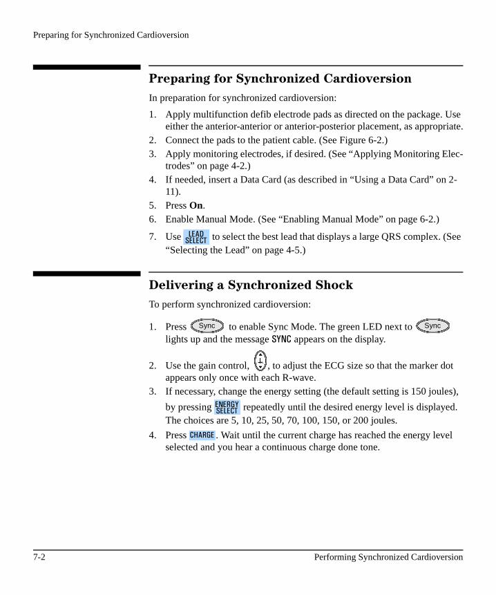
Preparing for Synchronized Cardioversion
Preparing for Synchronized Cardioversion
In preparation for synchronized cardioversion:
1. Apply multifunction defib electrode pads as directed on the package. Use either the anterior-anterior or anterior-posterior placement, as appropriate.
2. Connect the pads to the patient cable. (See Figure 6-2.)3. Apply monitoring electrodes, if desired. (See “Applying Monitoring Elec-
trodes” on page 4-2.)4. If needed, insert a Data Card (as described in “Using a Data Card” on 2-
11).5. Press On.6. Enable Manual Mode. (See “Enabling Manual Mode” on page 6-2.)
7. Use to select the best lead that displays a large QRS complex. (See “Selecting the Lead” on page 4-5.)
Delivering a Synchronized Shock
To perform synchronized cardioversion:
1. Press to enable Sync Mode. The green LED next to lights up and the message ���� appears on the display.
2. Use the gain control, , to adjust the ECG size so that the marker dot appears only once with each R-wave.
3. If necessary, change the energy setting (the default setting is 150 joules),
by pressing repeatedly until the desired energy level is displayed. The choices are 5, 10, 25, 50, 70, 100, 150, or 200 joules.
4. Press . Wait until the current charge has reached the energy level selected and you hear a continuous charge done tone.
���*������
Sync Sync
���.7�������
���.7�
7-2 Performing Synchronized Cardioversion

Delivering a Synchronized Shock
7
Figure 7-1: Charging in Sync Mode
If desired, you may increase or decrease the selected energy level after
pressing , by pressing repeatedly until the desired energy level is displayed. The defibrillator charges to the modified energy level automatically. Wait until the current charge reaches the selected energy level before proceeding.
5. Make sure no one is touching the patient or anything connected to the patient. Call out “Clear.” Then press and continue to hold down until the shock is delivered.
The defibrillator shocks with the next detected R-wave.
WARNING Defibrillation current can cause operator or bystander injury. Do not touch the patient, or equipment connected to the patient, during defibrillation.
ENERGYSELECT
HR ALARM LEADSELECT
DISARM
Shocks:000:00:8
78 Pads
SpO2
150 J87 J
Sync
���.7� ���.7�������
����� �����
M3500B HeartStart XLT Defibrillator/Monitor 7-3
Disabling Sync Mode
Delivering Additional Synchronized Shocks
If additional synchronized shocks are indicated, make sure Sync Mode is still enabled and repeat steps 2-5. In its default configuration, the HeartStart XLT remains in Sync Mode after a shock is delivered, as indicated by the message
�$� on the display and the lighted green LED next to .
The HeartStart XLT can be configured to exit Sync Mode after each shock is delivered.
Disabling Sync Mode
To disable Sync Mode, press . The green LED next to goes out and the message �$� is no longer displayed. Sync Mode is also disabled when you exit Manual Mode.
Sync
Sync Sync
7-4 Performing Synchronized Cardioversion

8 Pacing
8
Noninvasive transcutaneous pacing is a Manual Mode function that is used to deliver paced pulses to the heart. Paced pulses are delivered through multi-function defib electrode pads applied to the patient’s bare chest.
This chapter explains the pacing options and describes how to performpacing.
M3500B HeartStart XLT Defibrillator/Monitor 8-1

Demand Mode Versus Fixed Mode
Demand Mode Versus Fixed Mode
The HeartStart XLT can deliver paced pulses in either demand or fixed mode.
In demand mode, the pacer only delivers paced pulses when the patient’s heart rate is lower than the selected pacing rate.
In fixed mode, the pacer delivers paced pulses at the selected rate.
Monitoring During Pacing
Multifunction defib electrodes pads can not be used to monitor the ECG and deliver paced pulses simultaneously. The HeartStart XLT always uses the 3- or 5-lead ECG cable and monitoring electrodes as the source of ECG during pacing.
In demand mode, ECG electrodes must be used, because the HeartStart XLT uses the R-wave detection from this monitoring source to determine if a paced pulse should be delivered.
In fixed mode, ECG electrodes may or may not be used; however, an ECG will only be displayed if ECG monitoring electrodes are used.
WARNING Use demand mode pacing whenever possible. Use fixed mode pacing when motion artifact or other ECG noise makes R-wave detection unreliable.
WARNING Heart rate displays and alarms function during pacing, but they can be unreliable. Observe the patient closely while pacing. Do not rely on heart rate alarms or the indicated heart rate as a measure of the patient’s perfusion status.
8-2 Pacing
Preparing for Pacing
8
Preparing for Pacing
In preparation for pacing:
1. Apply multifunction defib electrode pads as directed on the package. Use either the anterior-anterior or anterior-posterior placement, as appropriate.
2. Connect the pads to the patient cable. (See Figure 6-2.)3. If needed, insert a Data Card (as described in “Using a Data Card” on 2-
11).4. Press On.5. Enable Manual Mode. (See “Enabling Manual Mode” on page 6-2.)
In addition, for demand mode pacing:
1. Apply monitoring electrodes. (See “Applying Monitoring Electrodes” on page 4-2.)
2. Use to select the best lead with an easily detectable R-wave (See “Selecting the Lead” on page 4-5.) If you do not select a lead (i.e. pads is the selected ECG source), �� �4 is automatically selected when the pacing function is turned on.
NOTE If pacing for long periods of time, new monitoring electrodes and multifunc-tion defib electrode pads may need to be applied periodically. Refer to the manufacturer’s documentation for how often to change monitoring electrodes or defib pads.
���*������
M3500B HeartStart XLT Defibrillator/Monitor 8-3

Pacing
Pacing
To perform pacing:
1. Press . The green LED next to lights up and the dia-logue box appears.
Figure 8-1 Pacing Display
The message ���) indicates that the pacing function is on but paced pulses are not being delivered. The pacer turns on in the mode last used.
2. Verify that the dot markers appears near the middle of the QRS complexes of the ECG.
If the dot markers do not appear, or are in the wrong location, adjust the ECG size or select another lead. (See “Monitoring the ECG” in Chapter 4.)
The ECG will only appear if the 3- or 5-lead monitoring cable and elec-trodes are used.
3. Press to change to fixed mode, if R-wave detection is unreliable.
The pacing dialogue box displays the current mode. To switch back to
demand mode, press again.
Pacer Pacer
ENERGYSELECT
HR ALARM LEADSELECT
CHARGE
Shocks:000:00:8
78 Lead II
SpO2
150 J
Pacer StopDemand Mode70ppm 30mA
Mode
Mode
8-4 Pacing

Pacing
8
4. Adjust the rate to the desired number of paced pulses per minute (ppm).
Press up, , or down, , on to increase or decrease the num-
ber of paced pulses per minute.
5. Press to start pacing.
The message ���"$0 indicates that paced pulses are being delivered in the selected mode at the rate and output level displayed.
Figure 8-2: Pacing Display
NOTE Pacing will not start if there is a problem with the multifunction defib elec-trode pads connections or, in demand mode, a problem with the ECG monitor-ing electrodes connections. Should a problem exist, a system message is displayed. Be attentive to system messages.
Rate
StartStop
ENERGYSELECT
HR ALARM LEADSELECT
CHARGE
Shocks:000:00:8
78
SpO2
150 J
PacingDemand Mode70ppm 30mA
Lead II
M3500B HeartStart XLT Defibrillator/Monitor 8-5

Changing Pacing Modes
6. Increase the output until cardiac capture occurs.
Press up on to increase the output in increments of 10 mA.
7. Decrease the output to the lowest level that still maintains capture.
Press on to decrease the output in increments of 5 mA.
Press to stop pacing. Press to exit the pacing function. The
green LED next to the button goes out, indicating pacing is no longer active.
Changing Pacing Modes
If paced pulses are being delivered, you must stop pacing before changing the pacing mode:
1. Press to stop pacing.
2. Press to change the mode.
3. Adjust the rate, if needed.
4. Press to resume pacing.
5. Adjust the output, as needed to obtain capture.
Defibrillating During Pacing
If the patient must be defibrillated during pacing, follow the procedure for defibrillating in Manual Mode on page 6-4.
Pacing is automatically turned off when you charge the defibrillator and the pacing dialogue box is removed from the display. After a shock, pacing remains off.
To resume pacing, refer to “Pacing” on page 8-4. When you resume, the rate, mode, and output settings start at the settings selected prior to defibrillation.
Output
Output
StartStop Pacer
StartStop
Mode
StartStop
8-6 Pacing

Troubleshooting
8
Troubleshooting
The table below lists the pacing-related system and momentary messages that you may encounter during pacing.
Table 8-1 Pacing System Messages
Message Possible Cause Corrective Action
�� #���� � The selected monitoring lead is not making proper contact with the patient.
� Pacing was attempted in demand mode without monitoring electrodes attached.
� Check that the monitoring electrodes are properly applied.
� Check that the monitoring cable and electrodes are properly connected.
������5�"(,� The pacing system is not func-tioning.
Remove the device from active use and call for service.
������,�),�����
High patient impedance is resulting in the delivery of less current to the patient than specified in the output current setting.
Check that the pads are applied properly.
���)������ is pressed while
paced pulses are being deliv-ered.
Stop pacing before changing the pacing mode.
��4$���"!, or one of the other
pacing function keys, is pressed when Manual Mode is not active.
Make sure Manual Mode is active before pressing
or one of the other
pacing function keys.
Mode
Pacer
Pacer
M3500B HeartStart XLT Defibrillator/Monitor 8-7

9 Storing, Retrieving & Printing
9
This chapter describes how the HeartStart XLT creates a patient record, called an Event Summary, for later retrieval and printing. It covers how to mark events for storage in the Event Summary, as well as how to print individual events as they occur.
Overview
The HeartStart XLT automatically creates an Event Summary for each patient. The Event Summary is stored in the HeartStart XLT’s internal memory and on a Data Card (if one is used).
The internal Event Summary stores up to 300 pieces of critical information, called events, and 50 ECG strips (11 seconds each). Events include things such as charging, shocks, and alarm violations. In addition, you trigger an
event each time you press or .
Storage on a Data Card is limited only by available space on the card. In addi-tion to storing all of the events that occur, a continuous copy of the displayed ECG and Patient Contact Impedance is also stored.
You can print the internal Event Summary at any time. You can also configure the HeartStart XLT to print individual events automatically as they occur and, of course, you can activate printing of individual events and patient informa-
tion, at any time, by pressing .
To print the Event Summary stored on the Data Card, the information must first be downloaded to the HeartStart Event Review Data Managementsystem. Refer to the HeartStart Event Review Instructions for Use for instruc-tions.
MarkEvent
PrintStrip
PrintSummary
M3500B HeartStart XLT Defibrillator/Monitor 9-1

Marking Events
Marking Events
The button allows you to annotate the ECG strip at the point in time the button is pressed. In AED Mode, when monitoring is disabled, the event is marked with a . In Manual Mode, or when monitoring is enabled in AED Mode, you use the softkeys to select the annotation from the choices dis-played (See Figure 9-1)*. If no selection is made, the event is marked with a
.
Figure 9-1 Annotations
NOTE *In Australia and the U.K., ��4 is replaced by �*.� (adrenaline).
The marked event is stored in the Event Summary. If the printer is configured
to ��"$���$�/���, an ECG strip prints when is pressed. If the printer is configured to 8�#��$ � (�, the strip is 9 seconds and includes 6 seconds pre-ceding the event and 3 seconds following the event. If ���*(� is configured, a 3 second ECG strip prints in real time. To stop printing before the entire strip is printed, press .
MarkEvent
EPI ATRO LIDO OTHER
Pads
Shocks:000:00:8
72
CHARGEENERGYSELECT
150 J
MarkEvent
PrintStrip
9-2 Storing, Retrieving & Printing
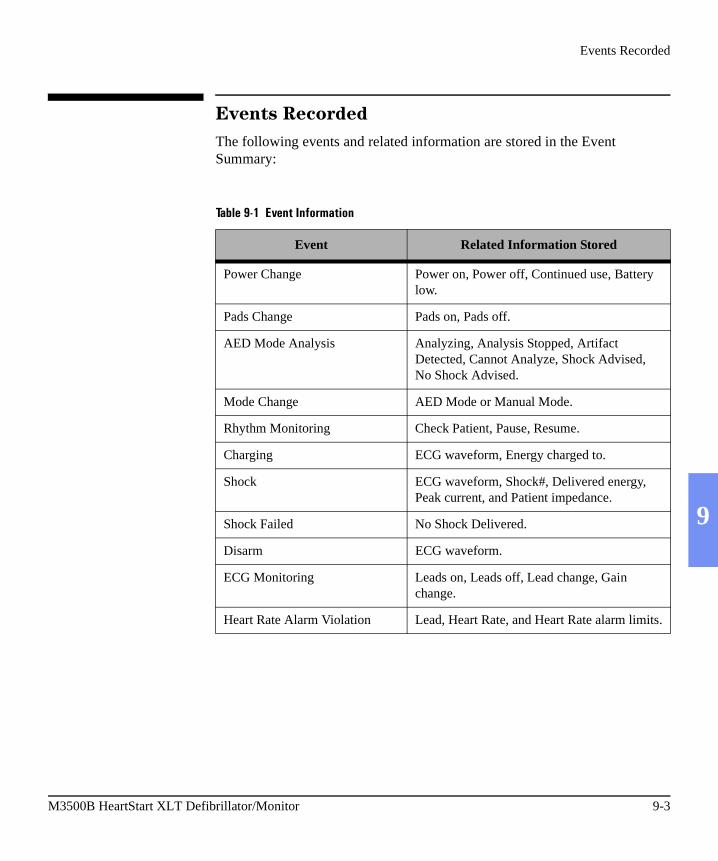
Events Recorded
9
Events Recorded
The following events and related information are stored in the EventSummary:
Table 9-1 Event Information
Event Related Information Stored
Power Change Power on, Power off, Continued use, Battery low.
Pads Change Pads on, Pads off.
AED Mode Analysis Analyzing, Analysis Stopped, Artifact Detected, Cannot Analyze, Shock Advised, No Shock Advised.
Mode Change AED Mode or Manual Mode.
Rhythm Monitoring Check Patient, Pause, Resume.
Charging ECG waveform, Energy charged to.
Shock ECG waveform, Shock#, Delivered energy, Peak current, and Patient impedance.
Shock Failed No Shock Delivered.
Disarm ECG waveform.
ECG Monitoring Leads on, Leads off, Lead change, Gain change.
Heart Rate Alarm Violation Lead, Heart Rate, and Heart Rate alarm limits.
M3500B HeartStart XLT Defibrillator/Monitor 9-3
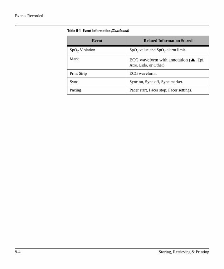
Events Recorded
SpO2 Violation SpO2 value and SpO2 alarm limit.
Mark ECG waveform with annotation ( , Epi, Atro, Lido, or Other).
Print Strip ECG waveform.
Sync Sync on, Sync off, Sync marker.
Pacing Pacer start, Pacer stop, Pacer settings.
Table 9-1 Event Information (Continued)
Event Related Information Stored
9-4 Storing, Retrieving & Printing

Creating a Patient Record
9
Creating a Patient Record
The HeartStart XLT creates an Event Summary patient record for each new patient. Each record is assigned a unique incident number. The HeartStart XLT keeps the Event Summary in its internal memory until you begin caring for a new patient. It assumes that:
The Continued Use feature allows you to change batteries or shut the Heart-Start XLT off briefly (for 2 minutes), while preserving the current patient record. Events recorded after the power interruption are appended to the patient record. Continued use also preserves alarm settings.
Table 9-2 Patient Record Summary
If: Then:
Power is off for more than 2 minutes and a new event is recorded
You are caring for a new patient. The last internal Event Summary is deleted; a new Event Summary is started and a new incident record is created on the Data Card.
Power is off less than 2 minutes You are continuing to care for the same patient. Additional events are appended to the Event Summary; the annotation "Continued Use" is printed on the Event Summary.
M3500B HeartStart XLT Defibrillator/Monitor 9-5

Printing the Internal Event Summary
Printing the Internal Event Summary
To print the internal Event Summary, press . To stop printing before
the complete summary is printed, press again or press .
The Event Summary includes the following information, in the order listed:
� a header with a place for you to write in the patient’s name and the operator’s name.
� a directory list of events that occurred during the incident and the time of their occurrence.
� ECG strips of the events in the directory list, where relevant.
Figure 9-2 shows the beginning of an Event Summary.
Figure 9-2 Event Summary
PrintSummary
PrintSummary
PrintStrip
Patient ___________________
Operator __________________
Device On 03 Jan 00 12:41:00
Last Event 03 Jan 00 01:09:04
Total Shocks 2Incident: 0000045Serial Number 123456789
Device OnAED Mode
Pads OnLeads On
AnalyzingShock AdvisedShock #1
AnalyzingShock AdvisedShock #2
Manual Mode
12:41:0012:41:0012:41:0112:41:0312:41:0312:41:1112:41:1712:41:2412:41:3112:41:3812:41:42
9-6 Storing, Retrieving & Printing

Printing the Internal Event Summary
9
The Event Summary also includes waveforms and the appropriate annotation for each of the following events:
Table 9-3 Event Waveform Information
Event Waveform Description
Shock Advised 11 seconds of ECG just prior to the message ������� !"# %
No Shock Advised 11 seconds of ECG just prior to the message ���������� !"# %
Cannot Analyze 11 seconds of ECG just prior to the message ��$$����$�(9%
Shock Delivered 11 seconds; 3 seconds prior to the shock, plus 8 seconds after the shock.
Print Strip 11 seconds; 3 seconds prior to
being pressed, plus 8 seconds after
is pressed.
Mark Event11 seconds; 3 seconds prior to being pressed, plus 8 seconds after
is pressed.
ECG or SpO2 Alarm 11 seconds; 3 seconds prior to the alarm, plus 8 seconds after the alarm.
PrintStrip
PrintStrip
MarkEvent
MarkEvent
M3500B HeartStart XLT Defibrillator/Monitor 9-7

Printing Events
Printing Events
The HeartStart XLT can be configured to print automatically when certain events occur. The table below lists these events and the length of the strip printed, depending on whether the printer is configured to print real-time or with a 6-second delay.
Printing is configured independently for each of these events. You can stop
the printing before it has printed the entire strip by pressing .
To print additional events that you observe in the course of caring for your
patient, press . An ECG strip will print continuously until you press
a second time to stop printing. If the printer is configured to have a 6-second delay, the printout contains an additional 6 seconds of the ECG that
occurred just prior to pressing .
Table 9-4 Printing Events
EventReal-Time
Strip LengthDelayed
Strip Length
Defibrillator charges continuous 6 seconds just prior to charging, plus continuous printing throughout the charge duration.
Shock Delivered 12 seconds 6 seconds just prior to shock, plus 12 seconds after shock.
Shock Failed 6 seconds 6 seconds just prior to the message ���������*("!� , plus 6 seconds after the message.
Defibrillator disarmed 6 seconds 6 seconds just prior to shock, plus 6 seconds after shock.
Alarm Violation 6 seconds 6 seconds just prior to alarm viola-tion, plus 6 seconds after alarm vio-lation.
pressed 6 seconds 6 seconds just prior to marking, plus 6 seconds after button pressed.
MarkEvent
PrintStrip
PrintStrip
PrintStrip
PrintStrip
9-8 Storing, Retrieving & Printing

10 Setting Up and Configuring the HeartStart XLT
10
This chapter describes how to set-up and configure your HeartStart XLT. It covers:
� Connecting Patient Cables� Arranging Accessories in the Carrying Case� Configuring the HeartStart XLT
Connecting/Disconnecting Patient Cables
This section describes how to connect and disconnect the:
� Pads Patient Cable� ECG Patient Cable (3- or 5-lead)� SpO2 Patient Cable
M3500B HeartStart XLT Defibrillator/Monitor 10-1

Connecting/Disconnecting Patient Cables
Connecting the Pads Patient Cable
To connect the pads patient cable to the defibrillator:
1. Align the white pointer on the pads patient cable with the white arrow on the defibrillator’s pads connector, as shown in Figure 10-1.
2. Insert the patient cable into the pads connector. Push until you hear it click in place.
Figure 10-1 Pads Patient Cable Connector
Pointer
Pads connector
10-2 Setting Up and Configuring the HeartStart XLT

Connecting/Disconnecting Patient Cables
10
Disconnecting the Pads Patient Cable
To disconnect the pads patient cable:
1. Rotate the green locking mechanism on the patient cable in the direction (clockwise), of the blue arrow on the defibrillator until it stops (as shown in Figure 10-2).
2. Hold the locking mechanism in this position as you pull the patient cable away from the defibrillator.
Figure 10-2 Disconnecting the Pads Patient Cable
Blue arrow
M3500B HeartStart XLT Defibrillator/Monitor 10-3

Connecting/Disconnecting Patient Cables
Connecting the ECG Patient Cable
To connect a 3- or 5-lead ECG patient cable:
1. Align the keyed patient cable plug with the slot on the ECG connector, as shown in Figure 10-3.
2. Push the patient cable firmly into the ECG connector, until the white por-tion is no longer visible.
Figure 10-3 ECG Patient Cable Connector
Disconnecting the ECG Patient Cable
To disconnect the ECG patient cable, gently pull the white patient cable plug out of the ECG connector, as shown in Figure 10-3.
10-4 Setting Up and Configuring the HeartStart XLT

Connecting/Disconnecting Patient Cables
10
Connecting the SpO2 Patient Cable
To connect the SpO2 patient cable:
1. Hold the connector with the flat side up, as shown in Figure 10-4.2. Insert the connector into the receptacle and push until the blue portion of
the connector is no longer visible.
Figure 10-4 Connecting the SpO2 Patient Cable
Disconnecting the SpO2 Patient Cable
To disconnect the SpO2 patient cable, gently pull it out of the SpO2 connector.
M3500B HeartStart XLT Defibrillator/Monitor 10-5
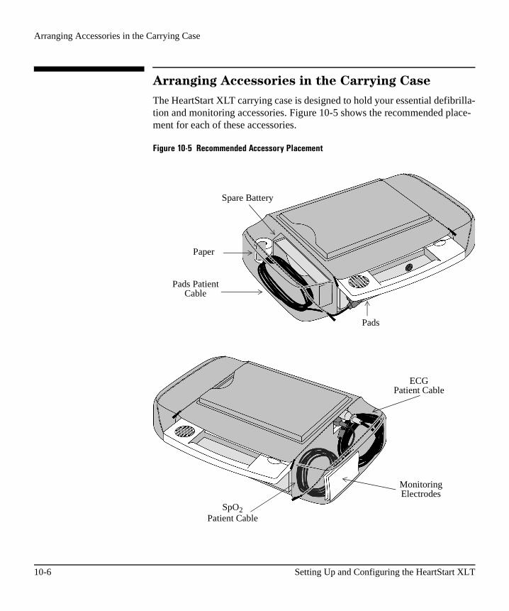
Arranging Accessories in the Carrying Case
Arranging Accessories in the Carrying Case
The HeartStart XLT carrying case is designed to hold your essential defibrilla-tion and monitoring accessories. Figure 10-5 shows the recommended place-ment for each of these accessories.
Figure 10-5 Recommended Accessory Placement
Spare Battery
Paper
Pads PatientCable
ECGPatient Cable
SpO2Patient Cable
MonitoringElectrodes
Pads
10-6 Setting Up and Configuring the HeartStart XLT

Configuring the HeartStart XLT
10
Configuring the HeartStart XLT
Configuration options allow you to customize the HeartStart XLT to best meet your needs. This section describes:
� How to access the configuration menu.� Configurable items and their setting options.� How to change the configuration. � How to save the configuration to a Data Card.� How to load the configuration from a Data Card.� How to print the configuration.
Accessing the Configuration Menu
There is a special combination of softkeys that, when pressed simultaneously, turn the HeartStart XLT on in Configuration Mode. For the purposes of exe-cuting this procedure, softkeys are assigned numbers as shown in Figure 10-6.
Figure 10-6 Softkey Numbers
M3500B HeartStart XLT Defibrillator/Monitor 10-7
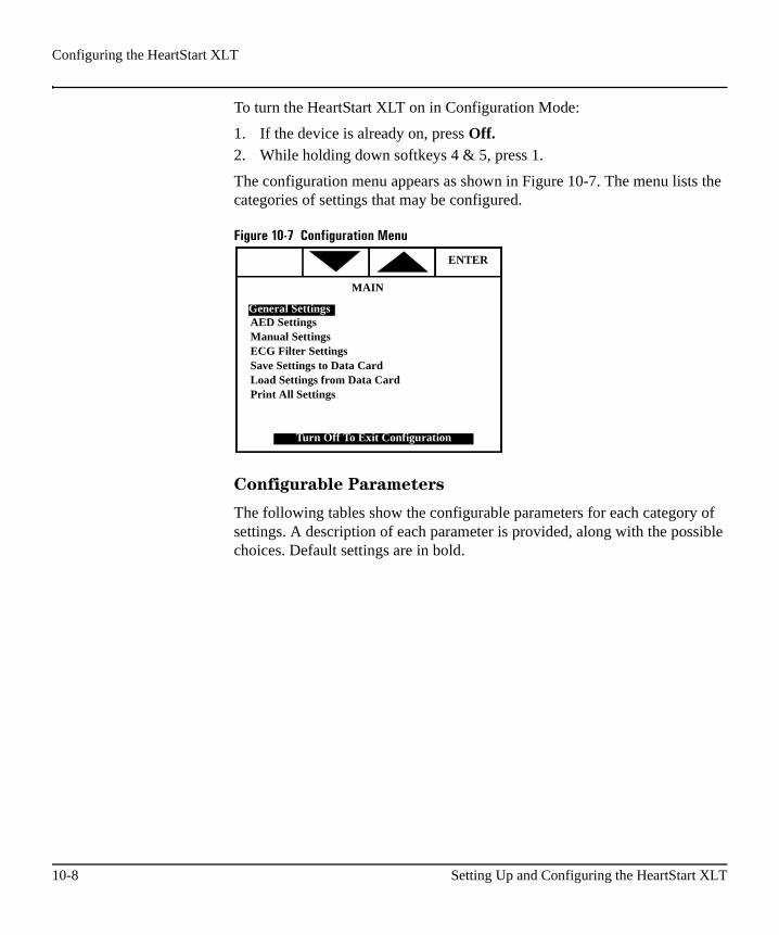
Configuring the HeartStart XLT
To turn the HeartStart XLT on in Configuration Mode:
1. If the device is already on, press Off.2. While holding down softkeys 4 & 5, press 1.
The configuration menu appears as shown in Figure 10-7. The menu lists the categories of settings that may be configured.
Figure 10-7 Configuration Menu
Configurable Parameters
The following tables show the configurable parameters for each category of settings. A description of each parameter is provided, along with the possible choices. Default settings are in bold.
ENTER
MAIN
AED SettingsManual SettingsECG Filter SettingsSave Settings to Data CardLoad Settings from Data CardPrint All Settings
Turn Off To Exit Configuration
General Settings
10-8 Setting Up and Configuring the HeartStart XLT
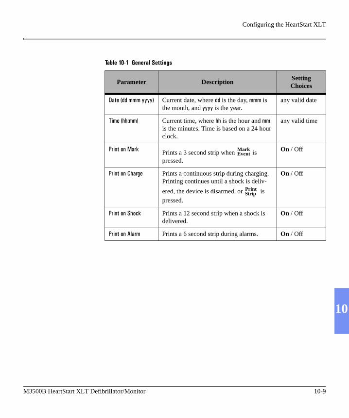
Configuring the HeartStart XLT
10
Table 10-1 General Settings
Parameter DescriptionSetting Choices
*���: �111�� Current date, where is the day, 111 is the month, and is the year.
any valid date
�"1�:�� 11� Current time, where �� is the hour and 11 is the minutes. Time is based on a 24 hour clock.
any valid time
��"$���$�/��� Prints a 3 second strip when is pressed.
On / Off
��"$���$�����0 Prints a continuous strip during charging. Printing continues until a shock is deliv-
ered, the device is disarmed, or is
pressed.
On / Off
��"$���$������ Prints a 12 second strip when a shock is delivered.
On / Off
��"$���$��(��1 Prints a 6 second strip during alarms. On / Off
Mark Event
Print Strip
M3500B HeartStart XLT Defibrillator/Monitor 10-9

Configuring the HeartStart XLT
��"$���*(� Captures what you just saw. All printed strips, including those generated by an event (mark, charge, shock or alarm), include an additional 6 seconds of infor-mation - the 6 seconds of information that occurred just prior to printing being initi-ated.
6 Sec Delay / No Delay
�����,(#�/����# Shows pace pulse markers on the ECG displayed, if an internal pacemaker is detected.
Leads & Pads / Leads Only
��7��� ���'( Selects the monitoring electrodes source. 3-lead / 5-lead
������$�/� Defines the operating mode when the device is turned on. Applies to a new use, not to a continued use.
AED / Manual
;.���)� Provides an audible beep with each QRS complex detected.
Manual / AED & Manual / Off
Table 10-1 General Settings (Continued)
Parameter DescriptionSetting Choices
10-10 Setting Up and Configuring the HeartStart XLT

Configuring the HeartStart XLT
10
Table 10-2 AED Settings:
Parameter DescriptionSetting Choices
��*���������"# Defines the maximum number of shocks to deliver before prompting ��������"$�+�������,(#+�4��� ��0"$���..
2, 3, 4
��������"#��"1� Defines the number of seconds that must pass before the next shock is considered the first shock of a new shock series, rather than the next shock of the current shock series.
30, 60, 90, 120, 150, 180, 210, Off
*!"��4$"�"�� ��$�(#"#
Initiates ECG analysis when the HeartStart XLT is turned on in AED Mode.
On, Off
�,��1��"��.&�$�(#"#
Initiates ECG analysis in between shocks within a shock series.
On, Off
.���1�/�$"���"$0 Monitors the ECG for potentially shockable rhythms when the HeartStart XLT is not ana-lyzing, defibrillating, or paused.
On, Off
<��������"$�=��"1�
Defines how often (in seconds) the ��������"$� prompt is repeated when Rhythm Mon-itoring detects a potentially shockable rhythm.
30, 45, 60, 90, Off
�,��)�$��������( Modifies Pause state prompts and replaces the Pause Timer with either the Post Shock CPR Timer or the "NSA" Timer, depending on the event preceding the Pause state.
Off/On
If �,��)�$�)������( is set to On, the following two configuration choices appear:
��#����������.��"1�-
Defines the duration of the Pause time (in sec-
onds) when is pressed and the time since the last shock is less than or equal to the ��������"#��"1� setting - typically at the com-pletion of a shock series.
30, 60, 120, 180�����
M3500B HeartStart XLT Defibrillator/Monitor 10-11

Configuring the HeartStart XLT
NOTE * If �,��)�$��������( is set to ���, the Pause Timer is used during the Pause state and appears as a configurable parameter. If �,��)�$��������(�is set to �$, either the ��#����������.��"1� or the <���=��"1� are used during the Pause state and appear as configurable parameters in place of ��,#��"1�.
NOTE If �,��)�$��������( is set to �$, the setting for the ��������"#��"1� must be < ��#����������.��"1� < �����"1�. Also, the ��������"#��"1� can not be config-ured to either ��� or 3>�.
2���2��"1�- Defines the duration of the Pause time (in sec-
onds) when is pressed and the time since the last shock is greater than the ��������"#��"1� setting - typically when ���������� !"# %�
30, 60, 120, 180
If �,��)�$��������( is set to Off, the following configuration choice appears:
<��,#=��"1�- Defines the duration of the pause time (in sec-
onds), when is pressed (when �,��)�$��������( is set to Off).
30, 60, 120, 180
The following two configuration choices are always available regardless of the �,��)�$��������( setting.
�� ��(�� Turns on ECG monitoring. On, Off
�)�3 Turns on SpO2 monitoring. Only listed as a configurable item if the SpO2 option was pur-chased.
On, Off
Table 10-2 AED Settings: (Continued)
Parameter DescriptionSetting Choices
�����
�����
10-12 Setting Up and Configuring the HeartStart XLT

Configuring the HeartStart XLT
10
Table 10-3 Manual Settings
Setting the Manual Mode Password
When Manual Mode Security is set to On (see “Modifying the Configuration” on page 10-15), the password entry screen is displayed. Use the softkeys on the top of the display to enter a four digit password.
Figure 10-8 Password Entry Screen
Parameter Description Choices
/�$,�(�/� ���,�"�
Requires entry of a password to access Manual Mode.
On, Off
�$������������ Determines if the Sync function stays on after a synchronized shock is delivered.
On, Off
1 2 3 4
Enter Password
_ _ _ _
CANCEL
M3500B HeartStart XLT Defibrillator/Monitor 10-13

Configuring the HeartStart XLT
Table 10-4 ECG Filter Settings
Item Description Setting Choices
����"$�5"(�� Selects the setting used to filter out AC line noise.
60 Hz, 50 Hz
�� #���7�����*"#)(�
Selects the display filter frequency for the pads ECG.
Monitor (.15-40Hz), EMS (1-30 Hz)
�� #���7�������"$��
Selects the printer filter frequency for the pads ECG.
Monitor (.15-40Hz), EMS (1-30 Hz)
�� #���7�����*"#)(�
Selects the display filter frequency for the monitoring electrodes ECG.
Monitor (.15-40Hz), EMS (1-30 Hz)
�� #���7�������"$��
Selects the printer filter frequency for the monitoring electrodes ECG.
Diag (.05 - 150 Hz), EMS (1 - 30 Hz, Monitor (.15 - 40 Hz)
10-14 Setting Up and Configuring the HeartStart XLT

Configuring the HeartStart XLT
10
Modifying the Configuration
To modify the configuration, from the main menu:
1. Use and to highlight the desired category of settings.
2. Press .
3. Use and to highlight the item you want to change.
4. Press .
5. Use the softkeys ( , , or ,) to select the desired setting. To
select the default setting, press .
6. Press to save the change. To exit without making the change, press
.
7. Press to return to the main menu.
To make additional changes, repeat steps 1-7.
Returning to the Default Configuration
Press and on simultaneously, while in the main configuration menu, to return all settings to their default settings. Although there is no visi-ble change in the display, default settings are restored.
����.
����7�
����
���*�5����
��?�
������
/�4�
M3500B HeartStart XLT Defibrillator/Monitor 10-15
Configuring the HeartStart XLT
Saving Settings to a Data Card
Configuration settings may be saved to a Data Card and used to load the same configuration into other HeartStart XLTs or to restore the configuration, if necessary.
To save the configuration:
1. Make sure a Data Card is in the HeartStart XLT before turning the unit on.2. Select ��!����"$0#����*������� from the main configuration menu.
3. Press in response to the question ��!����"$0#����*������� @.
The HeartStart XLT saves the configuration settings to the Data Card and returns to the main configuration menu.
Loading Settings from a Data Card
To load configuration settings:
1. Make sure a Data Card is in the HeartStart XLT.2. Select ��� ����"$0#����1�*������� from the main configuration menu.
3. Press in response to the question ��� ����"$0#����1�*������� @.
The HeartStart XLT loads the configuration settings from the Data Card and returns to the main configuration menu.
Printing Settings
To print the configuration settings, select ��"$���((����"$0# from the main config-uration menu.
��?�
���*
10-16 Setting Up and Configuring the HeartStart XLT

11
11 Maintaining the HeartStart XLT
This chapter describes how to care for your HeartStart XLT Defibrillator/Monitor and its accessories. It provides:
� Operational checks,� Battery maintenance procedures,� Instructions on loading printer paper,� Cleaning instructions, � Instructions for removing and replacing the carrying case,� A list of approved supplies and accessories, and� Instructions for disposal of the device.
The operational checks described must be performed at the specified intervals in order to help prevent and detect electrical and mechanical problems. The battery maintenance procedures specified must be adhered to in order to ensure that your batteries have the energy required to operate the defibrillator and deliver the appropriate therapy.
M3500B HeartStart XLT Defibrillator/Monitor 11-1
Operational Checks
Operational Checks
The following operational checks are intended to quickly verify the proper operation of the HeartStart XLT. Perform these checks regularly, at the inter-vals specified, along with visual inspection of the device and all cables, con-trols, accessories and supplies. Also regularly check expiration dates of all supplies, such as multifunction defib electrode pads and monitoring electrodes.
Before You Begin
Before you run the Shift/System Check, be aware of the following conditions:
� Do not touch any of the controls on the HeartStart XLT while the Shift/System Check is running.
� If a 5�"(,� or ��!"���$"� message is displayed, or if an unexpected �����#� �result is displayed, check that the test is set up correctly. Make sure that:� the paper is in the printer� the test load is attached� a Data Card with enough space is inserted into the HeartStart
XLT� a charged battery is inserted into the HeartStart XLTRun the Shift/System Check again, ensuring that no one touches any of the controls on the defibrillator unless prompted to do so.
� If the Data Card is full, the message ��!"���$"� appears at the bottom of the screen and the message *������� �5,(( appears at the top of the screen. Replace the Data Card and perform the Shift/System Check again. If the message���!"���$"��continues to appear, do not use the device and call for service.
11-2 Maintaining the HeartStart XLT
Operational Checks
11
Every Shift
Perform a “Shift/System Check” every shift (see “Shift/System Check” on page 11-4) to verify that the HeartStart XLT is functioning properly and to ensure that necessary supplies and accessories are present and ready for use.
Every Month
Check expiration dates on multifunction defib electrode pads and monitoring electrodes every month. Replace them if the expiration date has passed.
Every Three Months
Perform a "Battery Capacity Test" on each battery, every three months, to ensure that your batteries meet the specifications for safe and effective use.
M3500B HeartStart XLT Defibrillator/Monitor 11-3
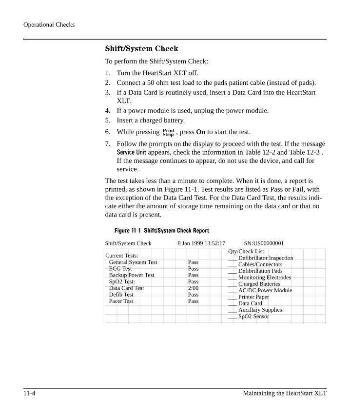
Operational Checks
Shift/System Check
To perform the Shift/System Check:
1. Turn the HeartStart XLT off. 2. Connect a 50 ohm test load to the pads patient cable (instead of pads).3. If a Data Card is routinely used, insert a Data Card into the HeartStart
XLT.4. If a power module is used, unplug the power module.5. Insert a charged battery.
6. While pressing , press On to start the test.
7. Follow the prompts on the display to proceed with the test. If the message ��!"���$"� appears, check the information in Table 12-2 and Table 12-3 . If the message continues to appear, do not use the device, and call forservice.
The test takes less than a minute to complete. When it is done, a report is printed, as shown in Figure 11-1. Test results are listed as Pass or Fail, with the exception of the Data Card Test. For the Data Card Test, the results indi-cate either the amount of storage time remaining on the data card or that no data card is present.
Figure 11-1 Shift/System Check Report
PrintStrip
Shift/System Check 8 Jan 1999 13:52:17 SN:US00000001
Current Tests:General System Test PassECG Test PassBackup Power Test PassSpO2 Test: PassData Card Test 2:00Defib Test PassPacer Test Pass
Qty/Check List:___ Defibrillator Inspection___ Cables/Connectors___ Defibrillation Pads___ Monitoring Electrodes___ Charged Batteries___ AC/DC Power Module___ Printer Paper___ Data Card___ Ancillary Supplies___ SpO2 Sensor
11-4 Maintaining the HeartStart XLT

Operational Checks
11
The report also lists additional checks that you should do. Perform each of these checks and record the results. The guidelines for completing the checks are as follows:
Defibrillator Inspection - make sure the HeartStart XLT is clean, clear of objects on top and has no visible signs of damage.
Cables/Connectors - make sure there are no cracks, broken wires, or other visible signs of damage. Make sure the connectors engage securely.
Supplies - make sure the carrying case has:
� two sets of multifunction defib electrode pads in sealed packages, within the expiration date
� an adequate supply of monitoring electrodes, within the expiration date
� alcohol wipes� hand towel� scissors� a razor� an extra roll of printer paper� a spare charged battery� a Data Card� SpO2 sensors (if monitoring SpO2)
M3500B HeartStart XLT Defibrillator/Monitor 11-5

Operational Checks
Power Supply
Battery - make sure:
� a charged battery is in the HeartStart XLT� another battery is charged or being charged� the batteries have no visible signs of damage
AC/Power Module
1. Make sure a battery is in the HeartStart XLT.2. Plug the power module into a power outlet and connect it to the Heart-
Start XLT.3. Verify that the power and charging indicators on the power module are
lit.4. Remove the battery from the HeartStart XLT and verify that the charg-
ing indicator on the power module is no longer lit. Replace the battery.
Printer - make sure the printer:
� has sufficient paper� prints properly
11-6 Maintaining the HeartStart XLT
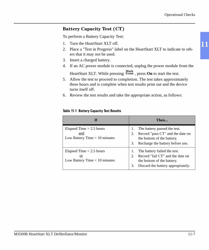
Operational Checks
11
Battery Capacity Test (CT)
To perform a Battery Capacity Test:
1. Turn the HeartStart XLT off.2. Place a "Test in Progress" label on the HeartStart XLT to indicate to oth-
ers that it may not be used.3. Insert a charged battery.4. If an AC power module is connected, unplug the power module from the
HeartStart XLT. While pressing , press On to start the test.5. Allow the test to proceed to completion. The test takes approximately
three hours and is complete when test results print out and the device turns itself off.
6. Review the test results and take the appropriate action, as follows:
Table 11-1 Battery Capacity Test Results
If Then...
Elapsed Time > 2.5 hours andLow Battery Time > 10 minutes
1. The battery passed the test.2. Record "pass CT" and the date on
the bottom of the battery.3. Recharge the battery before use.
Elapsed Time < 2.5 hours orLow Battery Time < 10 minutes
1. The battery failed the test.2. Record "fail CT" and the date on
the bottom of the battery.3. Discard the battery appropriately.
MarkEvent
M3500B HeartStart XLT Defibrillator/Monitor 11-7
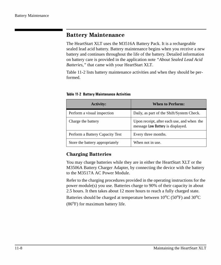
Battery Maintenance
Battery Maintenance
The HeartStart XLT uses the M3516A Battery Pack. It is a rechargeable sealed lead acid battery. Battery maintenance begins when you receive a new battery and continues throughout the life of the battery. Detailed information on battery care is provided in the application note “About Sealed Lead Acid Batteries,” that came with your HeartStart XLT.
Table 11-2 lists battery maintenance activities and when they should be per-formed.
Charging Batteries
You may charge batteries while they are in either the HeartStart XLT or the M3506A Battery Charger Adapter, by connecting the device with the battery to the M3517A AC Power Module.
Refer to the charging procedures provided in the operating instructions for the power module(s) you use. Batteries charge to 90% of their capacity in about 2.5 hours. It then takes about 12 more hours to reach a fully charged state.
Batteries should be charged at temperature between 10oC (50oF) and 30oC
(86oF) for maximum battery life.
Table 11-2 Battery Maintenance Activities
Activity: When to Perform:
Perform a visual inspection Daily, as part of the Shift/System Check.
Charge the battery Upon receipt, after each use, and when the message ��������� is displayed.
Perform a Battery Capacity Test Every three months.
Store the battery appropriately When not in use.
11-8 Maintaining the HeartStart XLT

Battery Maintenance
11
Battery Capacity
A fully charged M3516A battery, operating at room temperature, provides greater than 2.7 hours of monitoring or more than 50, 200-joule charge-shock cycles.
Battery Life-Expectancy
Life-expectancy of a battery depends on the frequency and duration of use. When properly maintained and stored, the life-expectancy of a battery is about 2 years. For more aggressive use models, life-expectancy may be less.
Storing Batteries
Batteries should be used regularly and rotated to distribute the use evenly. When storing batteries, make sure that the battery terminals do not come in contact with metallic objects.
Batteries should not be stored without charging for more than one month, if installed in the defibrillator, or more than three months, if not installed in the
defibrillator. Storage at temperatures between 15oC (59oF) and 30oC (86oF) is recommended to maximize life-expectancy.
CAUTION Storing at temperatures above 35oC (95oF) for extended periods of time will significantly reduce a battery’s life-expectancy.
Discarding Batteries
Batteries should be discarded two years after the first Test Date (as written on the battery’s back label), or sooner, if there are visual signs of damage or if they fail the Battery Capacity Test. Batteries should be discarded in an envi-ronmentally safe manner. Properly dispose of batteries according to local reg-ulations.
WARNING Do not disassemble, puncture, or incinerate batteries. Be careful not to short the battery terminals because this could result in a fire hazard.
M3500B HeartStart XLT Defibrillator/Monitor 11-9

Loading Printer Paper
Loading Printer PaperTo load printer paper:
1. Slide the printer door to the right until the paper roller pops up.2. If there is an empty or low paper roll in the printer, pull up on the plastic
removal tab to remove the roll.
Figure 11-2 Opening the Printer
11-10 Maintaining the HeartStart XLT

Loading Printer Paper
11
3. Place a new roll of printer paper (40457C/D) into the printer paper well, positioning the roll so that the end of the roll is on the top and the grid faces down. Be sure to push the roll down so that it is firmly seated in the paper well.
4. Pull the end of the paper past the paper roll. 5. Slide the printer door to the right and hold it open. Press the roller down
over the paper and release the door.
Figure 11-3 Loading Paper
M3500B HeartStart XLT Defibrillator/Monitor 11-11

Cleaning Instructions
Cleaning Instructions
Following are recommendations for cleaning the HeartStart XLT and its asso-ciated case, cables, etc.
Cleaning the HeartStart XLT
The following cleaning products may be used to clean the exterior surfaces of the HeartStart XLT, as well as the battery and data card:
� Isopropyl alcohol (70% in water)� Mild soap and water� Chlorine bleach (3% in water)� Quaternary ammonium compounds, such as Lysol (10% in water)
When cleaning, be sure to avoid pouring fluids on the device and do not allow fluids to penetrate the exterior surfaces of the device. Use of a soft cloth is recommended for cleaning the display, to prevent scratching.
CAUTION The HeartStart XLT may not be autoclaved, ultrasonically cleaned, or immersed. Do not use abrasive cleaners or strong solvents such as acetone or acetone-based cleaners.
Cleaning the Carrying Case
Clean the carrying case by hand, using a mild soap and water. A brush may be used on stubborn spots and a fabric cleaner may be used to remove grease spots. Air dry the carrying case when cleaning is complete.
If it is necessary to remove the carrying case for cleaning, refer to directions on page 11-15.
11-12 Maintaining the HeartStart XLT

Cleaning Instructions
11
Cleaning the Printer Printhead
If the printout has light or varying density printing, clean the printhead to remove any buildup of paper residue.
To clean the printhead:
1. Slide the printer door to the right until the paper roller pops up.2. Pull up on the plastic removal tab to remove the roll of paper.3. Clean the printhead surface (above the brush) with a cotton swab dipped
in rubbing alcohol.4. Replace the roll of paper (see “Loading Printer Paper” on page 11-10).
Cleaning the Power Modules
The following cleaning products may be used to clean the exterior surfaces of the AC power modules:
� Isopropyl alcohol (70% in water)� Mild soap and water� Chlorine bleach (3% in water)� Quaternary ammonium compounds, such as Lysol (10% in water)
When cleaning:
� Avoid pouring fluids on the module. Do not allow fluids to penetrate the exterior surfaces of the module.
� Do not use abrasive cleaners or strong solvents such as acetone or acetone-based compounds.
M3500B HeartStart XLT Defibrillator/Monitor 11-13
Cleaning Instructions
Cleaning Pads, Electrodes & Cables
Defibrillation pads and monitoring electrodes are single use and do not require cleaning.
The pads cable may be cleaned with:
� Alcohol-free hand soap� 2% gluteraldehyde solution (such as Cidex)� Sodium hypochlorite (chlorine bleach) solution 10% in water� Quaternary ammonium compounds (such as Lysol)� Isopropyl alcohol
The ECG cable may be cleaned by wiping it with any of the following:
� 2% gluteraldehyde solution (such as Cidex®)� Alcohol-free hand soap� Chlorine bleach (100ml/l)
CAUTION Do not ultrasonically clean, immerse, autoclave or steam sterilize the pads or ECG cable.
Do not clean the ECG cable with alcohol. Alcohol can cause the plastic to become brittle and may cause the cable to fail prematurely.
To clean the SpO2 sensor and cable, follow the manufacturer’s instructions.
11-14 Maintaining the HeartStart XLT

Removing & Replacing the Carrying Case
11
Removing & Replacing the Carrying Case
To remove the carrying case from the HeartStart XLT, follow steps 1 through 7 in Figure 11-4.
After loosening the screws (step 6), lay the unit flat and lift the defib up off the metal mounting plates to disengage it from the two metal pins at the rear of the case. Then slide the defib out of the case as shown in step 7.
Figure 11-4 Removing the Carrying Case
M3500B HeartStart XLT Defibrillator/Monitor 11-15

Removing & Replacing the Carrying Case
To put the carrying case on the HeartStart XLT, follow the steps 1 through 7 in Figure 11-5.
Slide the unit into the case as shown in step 1, then lower it onto the two metal pins at the rear of the case before tightening the screws (step 2).
Figure 11-5 Putting the Carrying Case On
11-16 Maintaining the HeartStart XLT

Putting On the Manual Door
11
Putting On the Manual Door
To put on the manual door, align the door with the door hinges as shown in Figure 11-6. Then push, as shown in Figure 11-7, until the door snaps in place.
Figure 11-6 Aligning the Manual Door
Figure 11-7 Snapping the door in place
M3500B HeartStart XLT Defibrillator/Monitor 11-17

Supplies & Accessories
Supplies & Accessories
Approved supplies and accessories for the HeartStart XLT are listed in Table 11-3 . To order:
� In the USA, call 1-800-225-0230 (electrodes, cables, paper, etc.) or 1-800-934-7372 (HeartStart Pads adapters only).
� Outside the USA, contact your local Philips Medical Systems Sales Office, your authorized Philips Medical Systems Dealer or Distribu-tor, or visit our online store at www.medical.philips.com/cms and fol-low the Supplies link.
Table 11-3 Supplies and Accessories
Part Number Description
Paper
40457C 50 mm Strip Chart Thermal Paper - 1 box (10 rolls)
40457D 50 mm Strip Chart Thermal Paper - 1 box (80 rolls)
M3501A Multifunction Adult defib pads, AAMI.
M3502A Multifunction Adult defib pads, IEC.
M3503A Multifunction Pediatric defib pads, IEC.
M3504A Multifunction Pediatric defib pads, AAMI.
M3507A Defib pads cable, barrel connector.
M1781A 50 ohm defibrillator test load, barrel connector.
05-10200 HeartStart Pads Adapter, barrel connector. Connects to M3507A pads connector cable.
Defibrillation Pads, Pads Cables andTest Load (white twist lock connector)
11-18 Maintaining the HeartStart XLT
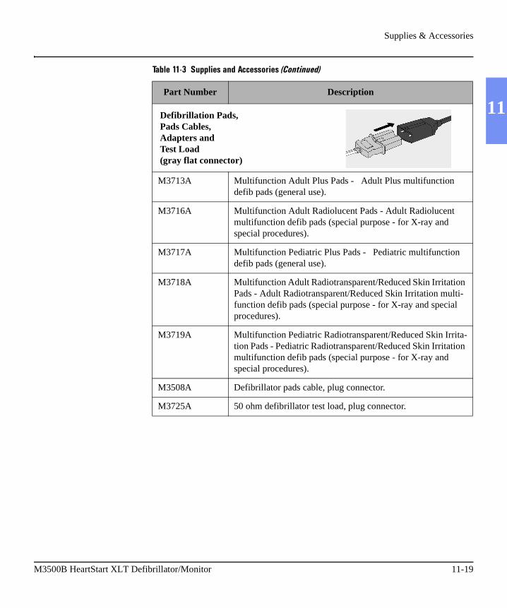
Supplies & Accessories
11
M3713A Multifunction Adult Plus Pads - Adult Plus multifunction defib pads (general use).
M3716A Multifunction Adult Radiolucent Pads - Adult Radiolucent multifunction defib pads (special purpose - for X-ray andspecial procedures).
M3717A Multifunction Pediatric Plus Pads - Pediatric multifunction defib pads (general use).
M3718A Multifunction Adult Radiotransparent/Reduced Skin Irritation Pads - Adult Radiotransparent/Reduced Skin Irritation multi-function defib pads (special purpose - for X-ray and special procedures).
M3719A Multifunction Pediatric Radiotransparent/Reduced Skin Irrita-tion Pads - Pediatric Radiotransparent/Reduced Skin Irritation multifunction defib pads (special purpose - for X-ray andspecial procedures).
M3508A Defibrillator pads cable, plug connector.
M3725A 50 ohm defibrillator test load, plug connector.
Table 11-3 Supplies and Accessories (Continued)
Part Number Description
Defibrillation Pads, Pads Cables, Adapters and Test Load(gray flat connector)
M3500B HeartStart XLT Defibrillator/Monitor 11-19

Supplies & Accessories
ECG Cables
M1733A 3-lead ECG Trunk cable, AAMI (8-pin).
M1734A 5-lead ECG Trunk cable, AAMI (8-pin).
M1735A 3-lead ECG Trunk cable, IEC (8-pin).
M1736A 5-lead ECG Trunk cable, IEC (8-pin).
M1580A 3-lead ECG Trunk cable, AAMI (8-pin)
M1600A 5-Lead ECG Trunk Cable, AAMI ((8-pin)
M1590A 3-lead ECG Trunk Cable, IEC (8-pin)
M1610A 5-Lead ECG Trunk Cable, IEC (8-pin)
Monitoring Electrodes
M2202A High-Tack Foam ECG Electrodes - 5 electrodes/pouch(300 electrodes/case)
SpO2 Cable/Sensors
M1191A Adult Reusable SpO2 sensor.
M1192A Pediatric Reusable SpO2 sensor.
M1194A Adult/Pediatric Ear Clip, Reusable SpO2 sensor
M1941A SpO2 extension cable (2 m).
M1943A Nellcor SpO2 Sensor adapter cable.
Data Card
M3510A Data Card.
Table 11-3 Supplies and Accessories (Continued)
Part Number Description
11-20 Maintaining the HeartStart XLT

Supplies & Accessories
11
Battery/Power Modules/ AdapterM3516A Sealed Lead Acid Battery.
M3517A AC power module.
M3518A DC Power Module
M3506A Battery charger adapter.
Extension Cable
M4748A Adapter extension cable
Carrying Case
M3509A Carrying case. (If a new Quick Reference Card is needed for the carrying case, it must be ordered separately.)
Table 11-3 Supplies and Accessories (Continued)
Part Number Description
M3500B HeartStart XLT Defibrillator/Monitor 11-21

Disposing of the HeartStart XLT
Prior to disposing of the HeartStart XLT, remove the battery. Then dispose of the device and its accessories in accordance with local standards.
WARNING Disposal of the device with the battery inserted presents a potential shock hazard.

12 Troubleshooting
12
If the HeartStart XLT detects an error or potential problem during use, it dis-plays a system or momentary message. In AED Mode, these messages are often accompanied by a voice prompt. This chapter describes the messages and what you should do in response. In addition, this chapter provides general troubleshooting tips and information on calling for service.NOTE For instructions for repair, or for further technical information, refer to the service manual, part number M3500-90900.
M3500B HeartStart XLT Defibrillator/Monitor 12-1

System Messages
System Messages
System messages remain on the display until the specified action is taken or no longer relevant. Each message is accompanied by a three second beep to alert you. Table 12-1 lists system messages.
Table 12-1 System Messages
Message Description Corrective Action
��������� #���'( The pads cable is not properly attached to the device.
Check the cable connection.
��$�"0,���"�$���#� The configuration is reset to the default settings.
� Reconfigure the HeartStart XLT. � If the message persists, call for ser-
vice.
*������� �*"#�'( The PC card is not in use because it is full, incompatible, absent, or inserted after the HeartStart XLT was turned on.
If possible, turn the HeartStart XLT off for more than 2 minutes, insert an empty, compatible Data Card, and turn the device on.
��7�5�,(� The ECG data acquisition system failed and data is unavailable from the 3- or 5-lead monitoring electrodes.
Remove the device from active use and call for service.
��������� The battery has sufficient capacity remaining to provide only about ten min-utes of monitoring time and six shocks before the HeartStart XLT shuts off.
Replace the battery with a fully charged battery.
�� #���� � The monitoring electrodes are not applied.
� The monitoring electrodes are not making proper contact with the patient.
� The monitoring cable is not con-nected.
� Check the monitoring electrodes are properly applied.
� Check the monitoring cable is prop-erly connected.
12-2 Troubleshooting

System Messages
12
����� # The multifunction defib electrode pads are not properly connected to the Heart-Start XLT.
Check the pads cable connection.
�� #���'(���� The pads cable is not connected to the defibrillator.
Check pads connector is locked in place.
�� #���� The pads are not making proper contact with the patient.
Make sure the pads are properly applied to the patient.
�����5�"(,� The pacing system is not functioning. Remove the device from active use and call for service.
������,�),����� High patient impedance is resulting in the pacer delivering less current to the patient than specified in the output current set-ting.
Check the pads are applied properly.
��!"���$"� Appears during a Shift/System Check. May indicate that the Data Card is full.OR
There is a system failure.
� Replace the Data Card.� Perform a Shift/System Check
� If ��!"���$"� continues to appear, do not use the device and call for service.
�#�1�5�"(,����(����� An internal error occurred. If this occurs during actual use:� Substitute another defib, if possible.
Remove this unit from clinical use and call for service.
� If no other defib is available, turn power off, then on. If unit turns on normally, use for this one incident. After this incident, remove from clini-cal use and call for service.
� If unit does not turn on normally, it cannot be used.
If this occurs during routine testing:Remove this unit from clinical use and call for service.
Table 12-1 System Messages (Continued)
Message Description Corrective Action
M3500B HeartStart XLT Defibrillator/Monitor 12-3

System Messages
�)�����'(���� The SpO2 cable is not connected to the device.
Attach the SpO2 cable to the HeartStart XLT.
�����5�"(,� A failure has occurred in the SPO2
circuitry.Remove the device from active use and call for service.
�)����"0���4$��� The level of ambient light is so high that the sensor cannot obtain an SpO2 reading or the sensor or cable is damaged.
� Cover the sensor with an opaque material.
� Check the sensor for damage; try another sensor.
�)�����$��,(#��"( The patient’s pulse is absent or too weak to be detected.
� Check that the sensor is applied prop-erly.
� Make sure the sensor site has a pulse.� Relocate the sensor to a site with
improved circulation.� Try another sensor.
�)��������"0$�( SpO2 signal is too low to give an accurate
reading.
� Check the sensor is applied properly.� Try another sensor type.
�)�����"#��"0$�( Excessive patient movement, electrical interference, or optical interference is present.
� Minimize patient movement or apply the sensor to a site with less move-ment.
� Secure the sensor cable loosely to the patient.
� Reduce sources of electrical or optical interference.
�)����$#���5�"( The SpO2 transducer is broken. Try another sensor.
Table 12-1 System Messages (Continued)
Message Description Corrective Action
12-4 Troubleshooting

System Messages
12
Momentary Messages
Momentary messages are temporary and only appear on the display for a few seconds. Each message is accompanied by a three second beep to alert you. Table 12-2 lists momentary messages.
Table 12-2 Momentary Messages
Message Possible Cause Corrective Action
��������� # The multifunction defib electrode pads are not making proper contact with the patient.
� Check the pads are applied to the patient, as directed on the pads’ pack-age.
� Replace the pads if the prompt contin-ues.
��������� # An attempt was made to begin pacing in Demand Mode without ECG leads attached to the patient.
Attach leads to patient.
*�"'�*"#��1 � The pads connection is compromised.� The mode is changed from Manual to
AED while the defibrillator is charged.
� is not pressed within 30 sec-onds of the defibrillator being charged.
� is pressed.
� Check the pads are applied to the patient properly.
� If a shock is indicated, deliver the shock before changing modes.
� To deliver a shock, press
within 30 seconds of the defibrillator being charged.
���������*("!� Patient impedance is too high. � Make sure the pads are applied prop-erly.
� Replace the pads, if necessary
�������"$�� Printer paper is absent or jammed; the printer door is not closed properly.
� Reload printer paper. � Make sure the door is closed properly.
�����
*4��./
�����
M3500B HeartStart XLT Defibrillator/Monitor 12-5

System Messages
*������� �5,(( � The incident is more than 2 hours in duration, causing the Data Card to fill.
� An empty Data Card was not inserted for the incident, causing the Data Card to fill sooner.
� None. A new Data Card can not be inserted during an incident.
� Use one Data Card per incident/patient to decrease the chance of the card filling.
*������� �4$���,)� The Data Card is removed during an inci-dent.
� None. The Data Card can not be re-inserted during an incident.
� Do not remove the Data Card during an incident.
*������� �����4$���!"� The Data Card is inserted while the Heart-Start XLT is on.
None. A Data Card must be inserted prior to turning the HeartStart XLT on for the current patient.
4$��1)��"'(�*������� A Data Card other than the M3510A is inserted.
Use only M3510A Data Cards.
���*������� ���#$� A Data Card is not in the HeartStart XLT. Turn the HeartStart XLT off and insert a Data Card prior to the first event for the patient.
��4$���"! The key pressed is currently inactive (i.e.
and are inactive in AED Mode).
Use the appropriate mode for the key.
���)����� is pressed while pacing pulses
are being delivered.
Stop pacing before changing the pacing mode.
Table 12-2 Momentary Messages (Continued)
Message Possible Cause Corrective Action
Sync Pacer
Mode
12-6 Troubleshooting

Troubleshooting Tips
12
Troubleshooting Tips
Table 12-3 lists some situations that you may encounter, causes, and actions to take.
Table 12-3 Troubleshooting Tips
Situation Cause Possible Solution
The HeartStart XLT does not turn on.
There is no power. OR
A corrupt Data Card may prevent the unit from powering on.OR
Hardware failure.
� Insert a fully charged battery.� Attach AC Power cord.
� Remove the Data Card� Insert a new Data Card, if available� Turn on the device
� Remove this unit from clinical use and call for service.
The display is blank except for “SYSTEM FAILURE CYCLE POWER”.
An internal error occurred. If this occurs during actual use:� Substitute another defib, if possible.
Remove this unit from clinical use and call for service.
� If no other defib is available, turn power off, then on. If unit turns on normally, use for this one incident. After this incident, remove from clini-cal use and call for service.
� If unit does not turn on normally, it cannot be used.
If this occurs during routine testing:� Remove this unit from clinical use and
call for service.
The HeartStart XLT appears to be on but the display is blank.
� The contrast needs adjusting.� The display has overheated.
� Adjust the contrast.� Avoid exposing the display to direct
sunlight on a hot day.
M3500B HeartStart XLT Defibrillator/Monitor 12-7
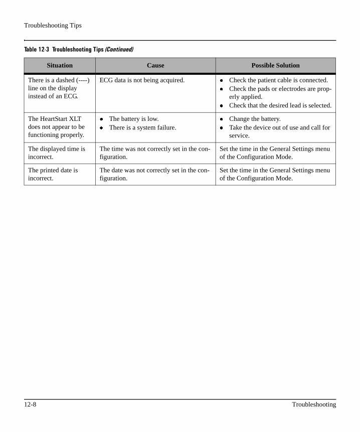
Troubleshooting Tips
There is a dashed (----) line on the display instead of an ECG.
ECG data is not being acquired. � Check the patient cable is connected.� Check the pads or electrodes are prop-
erly applied.� Check that the desired lead is selected.
The HeartStart XLT does not appear to be functioning properly.
� The battery is low.� There is a system failure.
� Change the battery.� Take the device out of use and call for
service.
The displayed time is incorrect.
The time was not correctly set in the con-figuration.
Set the time in the General Settings menu of the Configuration Mode.
The printed date is incorrect.
The date was not correctly set in the con-figuration.
Set the time in the General Settings menu of the Configuration Mode.
Table 12-3 Troubleshooting Tips (Continued)
Situation Cause Possible Solution
12-8 Troubleshooting
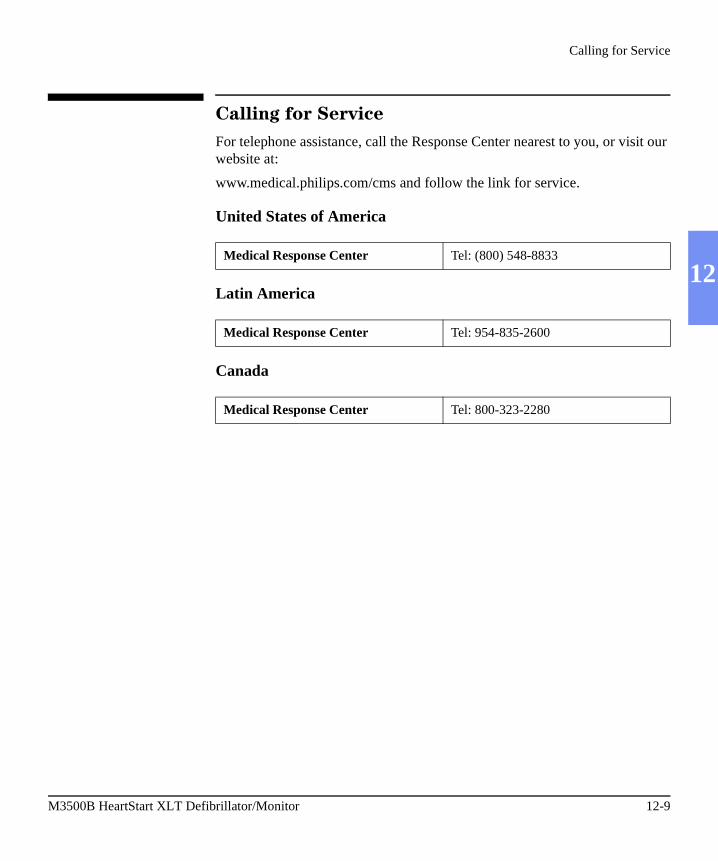
Calling for Service
12
Calling for Service
For telephone assistance, call the Response Center nearest to you, or visit our website at:
www.medical.philips.com/cms and follow the link for service.
United States of America
Latin America
Canada
Medical Response Center Tel: (800) 548-8833
Medical Response Center Tel: 954-835-2600
Medical Response Center Tel: 800-323-2280
M3500B HeartStart XLT Defibrillator/Monitor 12-9

Calling for Service
Other International Areas
Australia France
Tel: 131147 Tel: 0803 35 34 33
Germany Italy
Tel: 0180 5 47 50 00 Tel: 800-825087
Netherlands United Kingdom
Tel: 31 20 547 2555Fax: 31 29 547 2949
Tel: 00 44 7002 432584
Belgium (for Dutch) Belgium (for French)
Tel: 32 2 525 7102Fax: 32 2 525 71 91
Tel: 32 2 525 710 3Fax: 32 2 525 71 91
Spain Poland
Tel: 34 902 30 40 50Fax: 34 91 326 39 66
Tel: 48 22 5710499
Austria Finland
Tel: 43 1 60101 820 Tel: 09 6158 0400
Switzerland Russia
Tel: 0800 80 10 23 Tel: 7 095 933 0339Fax: 7 095 933 0338
12-10 Troubleshooting

13 Specifications & Safety
13
This section provides:
� Specifications for the HeartStart XLT,� Symbol definitions for symbols appearing on the HeartStart XLT, � A clinical performance summary,� Safety related information, and� Electromagnetic compatibility information.
M3500B HeartStart XLT Defibrillator/Monitor 13-1

Specifications
Specifications
Defibrillator
Waveform: Biphasic Truncated Exponential. Waveform parameters adjusted as a function of patient impedance.
Shock Delivery: Via multifunction defib electrode pads.
Charge Time: Less than 3 seconds to 200 Joules with a new, fully charged
M3516A SLA battery pack at 25oC. Less than 15 seconds to 200 Joules when powered by a M3517A or M3518A power module with no battery installed.
Patient Impedance Range: 25 to 180 Ohm.
Manual Mode
Manual Output Energy (Delivered): 5, 10, 25, 50, 70, 100, 150, 200 Joules.
Controls: On/Energy Select, Off, Charge/Disarm, Shock, ECG Lead Select, SpO2, HR Alarms, Manual Mode, Sync, Pacer, Pacer Start/Stop, Pacer Rate, Pacer Current, Pacer Mode, Display Contrast, ECG Gain, Vol-ume, Print Strip, Print Summary, Annotated Mark Event.
Indicators: LCD display for ECG waveform and text prompts, Audio alerts, QRS Beeper, Charging Tone, Charge Done Tone, Manual Mode LED, Sync LED, Pacer LED, Printer.
Armed Indicators: Charge done tone and available energy indicated on display.
Energy Selection: Front Panel "1" key.
Charge Control: Front Panel "2" key.
Shock Control: Front Panel "3" key.
Synchronizer: SYNC message appears on the monitor and is annotated on the printer (if printing while in Sync Mode). An audible beep sounds with each detected R-wave, while a tick mark on the monitor and printed strip indicate the discharge points. Synchronizer delay is less than 60 msec from peak R-wave to peak current of the defibrillation discharge.
13-2 Specifications & Safety

Specifications
13
Defibrillator (cont.)
AED Mode
AED Energy Protocol: Fixed Energy (150 Joules).
AED Shock Series: 2, 3, or 4.
Shock Series Timer: off, 30, 60, 90, 120, 150, 180, or 210 seconds.
Text and Voice Prompts: Extensive text audible messages guide user through protocol.
Protocol: Follows pre-configured settings. Can be configured to meet American Heart Association and European Resuscitation Council guide-lines.
AED Controls: On, Off, Pause/Resume, Analyze/Stop Analysis, Shock, Lead Select, SpO2, HR Alarms, Display Contrast, ECG Gain, Volume, Print Strip, Print Summary, Annotated Mark Event, Manual Mode Entry.
Indicators: LCD Display for ECG waveform and text prompts, Audio Alerts, Voice Prompts, QRS Beeper, Charging Tone, Charge Done Tone, Printer.
Armed Indicators: Charge Done Tone, Available Energy indicated on display, Voice Message.
Patient Analysis: Per protocol, evaluates patient ECG and signal quality to determine if a shock is appropriate and evaluates connection impedance for proper defibrillation pad contact.
Shockable Rhythms: Ventricular fibrillation with amplitude > 100 uV and wide complex ventricular tachycardia with rates greater than 150 bpm.
Sensitivity and Specificity: Meets AAMI guidelines.
M3500B HeartStart XLT Defibrillator/Monitor 13-3

Specifications
ECG Monitoring
Inputs: Single channel ECG may be viewed on display and printed. PADS ECG is obtained through two multifunction defibrillation electrode pads. Lead I, II, or III is obtained through the 3-lead ECG cable and separate moni-toring electrodes. With a 5-lead cable, lead aVR, aVL, aVF, or V can also be obtained.
Lead Fault: LEADS OFF message and dashed line appear on the monitor if a lead electrode or wire becomes disconnected.
Pad Fault: PADS OFF message and dashed line appear on the monitor if a pad becomes disconnected.
Heart Rate Display: Digital readout on display from 15 to 300 bpm, with an accuracy of 10%.
Heart Rate Alarms: Configurable pairs of low and high heart rate alarm lim-its: 30 to 100, 60 to 140, 90 to 160, and 120 to 200 bpm.
Defibrillation Patient Cable Length: 7 ft (2.13 m).
ECG Cable Length: 10 ft (3.05 m).
Common Mode Rejection: Greater than 90 dB measured per AAMI stan-dards for cardiac monitors (EC 13).
ECG Size: 2.5, 5, 10, 20, 40 mm/mV.
Frequency Response:
AC Line Filter: 60 Hz/50Hz.
Pads ECG for Display: Monitor (.15-40 Hz)/EMS (1-30 Hz).Pads ECG for Printer: Monitor (.15-40 Hz)/EMS (1-30 Hz).
Leads ECG for Display: Monitor (.15-40 Hz)/EMS (1-30 Hz).Leads ECG for Printer: Diag (.05-150 Hz)/EMS (1-30 Hz)/
Monitor (.15-40 Hz).
Patient Isolation (defibrillation proof):
ECG: Type CFSpO2: Type CFDefib: Type BF (multi-function defib electrode pads)
+_
13-4 Specifications & Safety

Specifications
13
Display
Display Size: 96 mm x 72 mm.
Display Type: Transflective active matrix LCD with LED backlight.Display Resolution: 320 x 240 pixels.Sweep Speed: 25 mm/s nominal (stationary trace; sweeping erase bar).
Viewing Time: 4 seconds.
Thermal Array Printer
Continuous Real Time Strip: User starts and stops the print strip. The Print Strip prints the selected ECG lead with the following data:
HEADER 1: Date, Time, Heart Rate, the SpO2 Value (if available), and the text "Delayed" if the recording has been configured for Delayed Mode. Prints every 12 seconds.
HEADER 2: Current mode (AED/Manual) the current Lead, the current Gain, filter setting, the text "Sync" if Sync has been enabled, and the Pacer Settings (consisting of the Pacer Mode, Rate, and Current (if currently pac-ing the patient). Prints every 12 seconds, with Header 1.
HEADER 3: Changes in Mode, Gain, Lead, Sync, and Pacer Settings.
FOOTER: Drug Annotations, HR/SpO2 limits on a Limit Alarm, the Results of an Analysis in AED Mode (No Shock Advised, Shock Advised, or Cannot Analyze), Charging to xxxJ, Shock Delivered, No Shock Deliv-ered, Disarm, Battery Low, Battery Critical.
SYMBOLS: Mark Triangle (for presses of the Mark key), an Alarm Bell (Alarm Limit Violations), Lightening Bolt (Shock Delivered), Vertical stripe Boundries/Pacer/Sync Tick Marks).
Event Printing: Mark Event key automatically documents events and ECG during defibrillation episodes. The Mark Event key can annotate the event with one of the following labels: Epinephrine, Atropine, Lidocaine, and Other.
M3500B HeartStart XLT Defibrillator/Monitor 13-5

Specifications
Thermal Array Printer (cont.)
Auto Printing: The printer can be configured to automatically print on Mark, Charge, Shock and Alarm.
Delayed Printing: The printer can be configured to run real time or with a six second delay.
Reports: The following can be printed: Event Summary, Configuration, Extended Self Test, System Log.
Speed: 25 mm/s with an accuracy of 5%.
Amplitude Accuracy: 10% or 50 uV, whichever is greater.
Paper Size: 50 mm by 30 m (100 ft).
Battery and Battery Power Module
Battery Type: 2 Ah, 12V, rechargeable, Sealed Lead Acid.
Battery Dimensions: 2.4" (H) x 0.94" (W) x 7.2" (D).61.7 mm (H) x 23.9 mm(W) x 182 mm (D).
Weight: 1.4 lb (0.65 kg).
Charge Time:
Approximately 14.5 hours to 100%, indicated by LED on power module.Approximately 2.5 hours to 90%, indicated by LED on power module.
Capacity: 2.7 hours ECG monitoring or 50 full-energy discharges or 2.1 hours ECG monitoring while pacing (with a new, fully charged battery and
temperature above 20oC).
Battery Indicators: LOW BATTERY message appears on monitor when at least 10 minutes of monitoring time and 6 maximum-energy discharges
remain (with a new battery and temperature above 20oC).
Battery Storage: Should not be stored above 40oC for extended periods of time.
Charger Output: Unit can be operated using Class I AC power module alone with no battery installed.
+_
+_ +_
13-6 Specifications & Safety

Specifications
13
Noninvasive Pacing
Waveform: Monophasic Truncated Exponential.
Current Pulse Amplitude: 10 mA to 200 mA (5 mA resolution); accuracy 10
mA - 50 mA 5 mA, 50 mA - 200 mA 10%.
Pulse Width: 20 ms with accuracy +0, -5 ms.
Rate: 30 ppm to 180 ppm (10 ppm increments); accuracy 1.5%.
Modes: Demand or Fixed Rate.
Refractory Period: 340 msec (40 to 80 ppm); 240 msec (90 to 180 ppm).
SpO2/Pulse Oximetry
Accuracy with:
M1191A sensor - 1 standard deviation 70% to 100%, 2.5%.M1192A sensor - 1 standard deviation 70% to 100%, 2.5%.M1194A sensor - 1 standard deviation 70% to 100%, 4.0%.
NELLCOR sensors - 1 standard deviation 80% to 100% 3.0%.
Resolution: 1%.
SpO2 Alarm Limits: Three preset low alarm limits: 90, 85, and 80%, default is off.
INOP Alerts: Triggered by disconnected sensor, noisy signal, light interfer-ence or low signal (non-pulsatile).
+_ +_
+_
+_
+_
+_
+_
M3500B HeartStart XLT Defibrillator/Monitor 13-7

Specifications
Event Storage
Internal Event Summary:
The internal Event Summary stores up to 300 events and up to 50 waveforms.
Events can be marked with a Mark Event symbol and, if configured for drug annotation, the following labels can be added: Epinephrine, Atropine, Lidocaine, or Other.
The Print Summary key on the front panel is used to print the internal Event Summary.
Data Card Event Summary:
One Data Card can store approximately 2 hours of continuous ECGwaveforms and events.
General
Dimensions: 4.05" (H) x 11.25" (W) x 13.65" (D).103 mm x 286 mm x 347 mm.
Weight: Standard Configuration weighs approximately 10 lbs (4.55 kg) including battery, full roll of paper, defibrillator patient cable, 1 set of pads, and without the carrying case.
13-8 Specifications & Safety

Specifications
13
Environmental
Temperature: 0o to 50oC operating, -20o to 70oC storage.
� Thermal paper may darken above 55oC.� Charging the battery at temperatures above 35oC may degrade battery
life.� Storing the battery for extended periods at temperatures above 40oC
will reduce battery capacity and degrade battery life.� Operating and storage specifications for electrodes may vary. Refer to
the manufacturer’s specifications for details.Humidity:
Up to 95% Relative Humidity
� Printer paper may jam if paper is wet.� Thermal printer may be damaged if wet paper is allowed to dry while
in contact with printer elements.
Altitude:
Operating: up to 15,000 ft.Shipping: up to 20,000 ft.
Shock (drops onto concrete): Unit survives 39" (1 m) drops onto all surfaces (faces, corners, and edges) enclosed in carrying case. Exposed handle surfaces survive 24" drops.
Vibration: Mil Std 810E 514.4 Category 6 Helicopter, General Storage, UH60.
Water Resistance: IPX4, splash proof per IEC 60529, with Data Card door closed.
EMC: Meets EN 60601-1-2. This ISM device complies with Canadian ICES-001.
Other Considerations: Equipment not suitable for use in the presence of a flammable anesthetic mixture with air, oxygen, or nitrous oxide.
Mode of Operation: Continuous.
M3500B HeartStart XLT Defibrillator/Monitor 13-9

Symbol Definitions
Symbol Definitions
The following table lists the meaning of each symbol shown on the HeartStart XLT and the M3516A battery.
Table 13-1 Defibrillator and Battery Symbols
Symbol Definition
On.
Off.
Shock hazard.
Attention - See operating instructions in user’s guide.
Power module input.
Input
!
13-10 Specifications & Safety

Symbol Definitions
13
Meets IEC type BF leakage current requirements and is defibrilla-tor protected (Patient Applied Part is isolated and defib-proof suit-able for direct patient contact except the heart or major arteries.)
Meets IEC type CF leakage current requirements and is defibrilla-tor protected (Patient Applied Part is isolated and defib-proof suit-able for direct patient contact including the heart and major arteries).
Alarms are active.
Alarms are inactive.
Recyclable material.
Must be recycled or disposed of properly.
Unlock.
IPX4 Ingress of fluids classification; protected against splashing water.
Table 13-1 Defibrillator and Battery Symbols (Continued)
Symbol Definition
M3500B HeartStart XLT Defibrillator/Monitor 13-11

Symbol Definitions
The following table lists the symbols that appear on the HeartStart XLT ship-ping carton.
Table 13-2 Shipping Carton Symbols
Symbol Definition
Atmospheric pressure range.
Temperature range.
Relative humidity range.
Recyclable paper product.
Fragile.
Right side up.
Do not get wet.
13-12 Specifications & Safety

Symbol Definitions
13
Shelf life.
Long-term storage conditions.
Short-term transport storage.
Table 13-2 Shipping Carton Symbols (Continued)
Symbol Definition
M3500B HeartStart XLT Defibrillator/Monitor 13-13

Clinical Performance Summary - Defibrillation
Clinical Performance Summary - Defibrillation
An international, multicenter, prospective, randomized, clinical study was conducted to assess the effectiveness of the SMART Biphasic waveform in out-of-hospital sudden cardiac arrests (SCAs), as compared to monophasic waveforms. The primary objective of the study was to compare the percent of patients with ventricular fibrillation (VF) as the initial monitored rhythm that were defibrillated in the first series of three shocks or less.
This section summarizes the methods and results of this study.
Methods
Victims of out-of-hospital SCA were prospectively enrolled in four emer-gency medical service (EMS) systems. Responders used either 150J SMART Biphasic AEDs or 200-360J monophasic waveform AEDs. A sequence of up to three defibrillation shocks were delivered. For the biphasic AEDs, there was a single energy output of 150J for all shocks. For monophasic AEDs, the shock sequence was 200, 200, 360J. Defibrillation was defined as termination of VF for at least five seconds, without regard to hemodynamic factors.
Results
Randomization to the use of monophasic or SMART Biphasic automatic external defibrillators (AEDs) was done in 338 SCAs from four emergency medical service systems. VF was observed as the first monitored rhythm in 115 patients. The biphasic and monophasic groups for these 115 patients were similar in terms of age, sex, weight, primary structural heart disease, cause or location of arrest, and bystanders witnessing the arrest or performing CPR.
The 150J SMART Biphasic waveform defibrillated 98% of VF patients in the first series of three shocks or less, compared with 69% of patients treated with monophasic waveform shocks. Outcomes are summarized in Table 13-3.
13-14 Specifications & Safety

Clinical Performance Summary - Defibrillation
13
Conclusion
The 150J SMART Biphasic waveform defibrillated at higher rates than 200-360J monophasic waveforms, resulting in more patients achieving return of spontaneous circulation (ROSC) (p=0.01). EMS system outcomes of survival discharge were not significantly different statistically. However, patients resuscitated with the lower energy SMART Biphasic waveform were more likely to have good cerebral performance (CPC, cerebral performance cate-gory) (p=0.04).
Table 13-3 Clinical Summary - Defibrillation
Biphasic PatientsNumber/(Percent)
Monophasic PatientsNumber/(Percent)
P Value(chi-square)
Defibrillation EfficacySingle shock only<2 shocks<3 shocks
52/54 (96%)52/54 (96%)53/54 (98%)
36/61 (59%)39/61 (64%)42/61 (69%)
<0.0001<0.0001<0.0001
Patients Defibrillated 54/54 (100%) 49/58 (84%) 0.003
Return of Spontaneous Circulation
41/54 (76%) 33/61 (54%) 0.01
Survival to Hospital Admission
33/54 (61%) 31/61 (51%) 0.27
Survival to Hospital Dis-charge
15/54 (28%) 19/61 (31%) 0.69
CPC = 1 (Good) 13/15 (87%) 10/19 (53%) 0.04
M3500B HeartStart XLT Defibrillator/Monitor 13-15

Clinical Performance Summary - Cardioversion
Clinical Performance Summary - Cardioversion
An international, multicenter, prospective, double-blinded, randomized, clini-cal trial was conducted to assess the effectiveness of the SMART Biphasic waveform in treatment of atrial fibrillation (AF), as compared to monophasic waveforms. The primary objective of the study was to determine the required energy for cardioversion of AF using the SMART Biphasic waveform, as compared with a monophasic damped sine waveform.
This section summarizes the methods and results of this study.
Methods
Patients enrolled for this study were adults scheduled for elective cardiover-sion of AF at one of 11 clinical sites. Clinicians used both a defibrillator deliv-ering the SMART Biphasic waveform, and one delivering a monophasic waveform. A sequence of up to five shocks was administered: four with the initial defibrillator, and a fifth cross-over shock was delivered with the other defibrillator if necessary. The sequence of energy settings was 100J, 150J, 200J through the first three shocks on either type of defibrillator. A fourth shock, if necessary, was delivered at 200J if the initial defibrillator was bipha-sic, and at 360J if the initial defibrillator was monophasic. The cross-over shock was 360J monophasic if the initial defibrillator was biphasic, and 200J biphasic if the initial defibrillator was monophasic. Successful cardioversion was defined as the occurrence of two P waves uninterrupted by atrial fibrilla-tion within 30 seconds of the shock.
Results
Randomization to the use of monophasic or SMART Biphasic defibrillators was done in 212 elective cardioversions involving 210 patients at eleven clin-ical sites in the United States and Europe. Of these, 203 results met the proto-col criteria for inclusion in this analysis. The biphasic and monophasic groups were similar in terms of age, sex, weight, current medical history, cause of heart disease, and estimated ejection fraction.
13-16 Specifications & Safety

Clinical Performance Summary - Cardioversion
13
The 150J SMART Biphasic waveform successfully converted far more patients with an initial 100J shock (60% compared with 22% for the monophasic waveform), and successfully converted patients at least as well with a maximum energy of 200J as the monophasic did with its maximum energy of 360J (91% compared to 85% for the monophasic waveform). Over-all, the biphasic waveform required fewer shocks (1.7, compared to 2.8 for the monophasic waveform) and lower delivered energy (217J, compared to 548J for the monophasic waveform). Outcomes are summarized in , Table 13-4.
Table 13-4 Clinical Summary - Cardioversion
Biphasic PatientsNumber (Percent)
Monophasic PatientsNumber (Percent)
P Value
CumulativeCardioversion Efficacy
Single shock only<2 shocks<3 shocks<4 shocks
58/96 (60%)74/96 (77%)86/96 (90%)87/96 (91%)
24/107 (22%)47/107 (44%)57/107 (53%)91/107 (85%)
<0.0001<0.0001<0.0001
.29
Skin “burn”NoneMild Moderate Severe
25/90 (28%)50/90 (56%)15/90 (17%)
0/90 (0%)
15/105 (14%)47/105 (45%)41/105 (39%)
2/105 (2%)
0.0001
Number of shocks 1.7 + 1.0 2.8 + 1.2 <0.0001
Cumulative delivered energy
217 + 176J 548 + 331J <0.0001
Skin reaction definitions: (Evaluated 24 - 48 hours after procedure)Mild - erythema, no tendernessModerate - erythema, tendernessSevere - blistering or necrosis, tenderness
M3500B HeartStart XLT Defibrillator/Monitor 13-17

Clinical Performance Summary - Cardioversion
Conclusion
The SMART Biphasic waveform cardioverted at higher rates than the monophasic damped sine waveform at each step of the protocol, although the cumulative biphasic rate after 4 shocks was not significantly different from the monophasic rate. Tissue damage was more pronounced in the monophasic population.
13-18 Specifications & Safety

Safety Considerations
13
Safety Considerations
The following general warnings and cautions apply to use of the HeartStart XLT. Additional warning and cautions specific to a particular feature are pro-vided in the appropriate section.
WARNING The HeartStart XLT is not intended to be deployed in settings or situations that pro-mote use by untrained personnel. Operation by untrained personnel can result in injury or death.
WARNING Remain attentive to the patient during the delivery of therapy. Delay in delivering a shock may result in a rhythm that was analyzed as shockable converting spontane-ously to non-shockable and could result in inappropriate delivery of a shock.
WARNING Use only the multifunction defib electrode pads, battery, and accessories listed in “Supplies & Accessories” on page 11-18. Substitutions may cause the HeartStart XLT to function improperly.
WARNING Use multifunction defib electrode pads prior to their expiration date. Discard pads after use. Do not reuse pads.
WARNING In AED Mode, the multifunction defib electrode pads must be in the anterior-anterior position as shown on the packaging. The HeartStart XLT was not designed to assess data acquired from pads in an anterior-posterior position.
M3500B HeartStart XLT Defibrillator/Monitor 13-19

Safety Considerations
WARNING Do not allow multifunction defib electrode pads to touch each other or to touch other ECG monitoring electrodes, lead wires, dressings, etc. Contact with metal objects may cause electrical arcing and patient skin burns during defibrillation and may divert current away from the heart.
WARNING During defibrillation, air pockets between the skin and multifunction defib electrode pads may cause patient skin burns. To help prevent air pockets, make sure the pads completely adhere to the skin. Do not use dried out pads; do not open pads package until just prior to use.
WARNING Never touch the patient or any equipment connected to the patient (including the bed or gurney) during defibrillation.
WARNING Do not operate the HeartStart XLT in standing water. When using the HeartStart XLT in wet environments, make sure the Data Card door is securely shut.
WARNING Do not immerse, or pour fluids on, any portion of the HeartStart XLT.
WARNING Do not use the HeartStart XLT in a flammable or oxygen-rich atmosphere. This can cause an explosion hazard.
WARNING Avoid connecting the patient to several devices at once. Leakage current limits may be exceeded. Do not use a second defibrillator on the patient while pacing with the HeartStart XLT.
13-20 Specifications & Safety

Safety Considerations
13
WARNING Avoid contact between the patient and conductive fluids and/or metal objects, such as the gurney. Contact with metal objects could cause unintentional current path-ways.
WARNING Operating the HeartStart XLT or its accessories in conditions outside the environ-mental specifications can result in device or accessory malfunction.
WARNING Avoid exposing the display to direct sunlight on a hot day. Overheating can occur and cause the display to black out, making the HeartStart XLT temporarily unusable.
WARNING Medical electrical equipment which does not incorporate defibrillator protection should be disconnected during defibrillation.
WARNING Electric shock hazards exist internally. Do not remove assembly screws. Refer ser-vicing to qualified personnel.
CAUTION This device has not been evaluated for use with electrosurgery equipment.
M3500B HeartStart XLT Defibrillator/Monitor 13-21
Electromagnetic Compatibility
Electromagnetic Compatibility
When using the M3500B defibrillator/monitor (with or without the M3517A AC Charger), electromagnetic compatibility with surrounding devices should be assessed.
A medical device can either generate or receive electromagnetic interference. Testing for electromagnetic compatibility EMC) of the M3500B with and without the appropriate accessories has been performed according to the inter-national standard for EMC for medical devices (IEC 60601-1-2). This IEC standard has been adopted in Europe as the European Norm (EN 60601-1-2).
The EMC standards describe tests for both emitted and received interference. Emission tests deal with interference generated by the device being tested. According to the EMC standards, the M3517A AC Power Module does not generate interference.
WARNING Radio frequency (RF) interference from nearby transmitting devices may degrade performance of the HeartStart XLT defibrillator/monitor. Electromagnetic compati-bility with surrounding devices should be assessed prior to using the defibrillator.
Reducing Electromagnetic Interference
The M3500B defibrillator/monitor and M3517A AC Charger are susceptible to interference from other RF energy sources and continuous, repetitive, power line bursts. Examples of other sources of RF interference are medical devices, cellular products, information technology equipment and radio/tele-vision transmission. Should interference be encountered, as demonstrated by artifact on the ECG or dramatic variations in SpO2 values, attempt to locate the source. Assess:
� Is the interference intermittent or constant?� Does the interference occur only in certain locations?� Does the interference occur only when in close proximity to certain
medical devices?� Does the SpO2 value change dramatically when the M3517A AC
Charger is unplugged?
13-22 Specifications & Safety

Electromagnetic Compatibility
13
Once the source is located, attempt to attenuate the EMC coupling path by distancing the defibrillator from the source as much as possible. If assistance is needed, call your local service representative.
Restrictions for Use
Artifact on the ECG caused by electromagnetic interference should be evalu-ated by a physician or physician authorized personnel to determine if it will negatively impact patient diagnosis or treatment.
Immunity Level
The EMC standards state that manufacturers of patient-coupled equipment must specify immunity levels for their systems. It is recognized that the Heart-Start XLT defibrillator/monitor is designed to receive and amplify low level signals in the same bandwidth as the interference.
Immunity is defined in the standard as the ability of a system to perform with-out degradation in the presence of an electromagnetic disturbance. Degrada-tion in ECG quality is a qualitative assessment which can be subjective.
Caution should, therefore, be taken in comparing immunity levels of different devices. The criteria used for degradation is not specified by the standard and may vary with the manufacturer.
NOTE For additional information about compliance with the EMC standards, please see the Philips Medical web site at http://www.medical.philips.com/cms and follow the regulatory link.
M3500B HeartStart XLT Defibrillator/Monitor 13-23

Index
AAC Power Module. See
Power modulesAccessories
arranging 10-6checking 11-5ordering 11-18, 13-19
AED Mode 3-1configuring 3-4, 10-10CPR 3-12defibrillation process
3-6display 2-5, 2-7ECG monitoring 4-1enabling from Manual
Mode 6-6events recorded 9-3Events Summary 9-2indications for use 1-3overview 1-1, 3-2, 3-3pausing 3-12, 3-15preparation 3-5re-analysis 3-11rhythm monitoring 3-
14specifications 13-3SpO2 monitoring 5-1training required 1-3troubleshooting 3-18
Alarmsheart rate 4-6, 8-2interruption of power
9-5SpO2 monitoring 5-8symbols 13-11
Analysis 3-8AED Mode 3-8re-analysis 3-11settings 3-4
Artifact Detected message 3-18
Asynchronous defibrillation 1-4
Asystole 1-5pacing 1-5
Attach Pads message 12-5Audiovisual controls 2-2,
2-3Automatic Re-analysis 3-
11setting 3-4, 10-11
BBatteries 1-2, 2-9
charging 11-8checking 11-6inserting and
removing 2-9maintenance 11-8operational checks 11-
3ordering 11-21specifications 11-9,
13-6storing and discarding
11-9symbols 13-10troubleshooting 12-2See also Power supply
Battery Capacity Test 11-7
Battery charger 11-21Bradycardia 1-5
i

Index
CCables
checking 11-5cleaning 11-14connecting 2-2, 3-6ECG 10-4Pads 3-6, 10-2SpO2 5-6, 10-5
Cal Pulse 2-3Carrying case
arranging accessories in 10-6
cleaning 11-12ordering 11-21removing & replacing
11-15Check Patient Timer
setting 10-11Check Printer message
12-5Cleaning
carrying case 11-12HeartStart XLT 11-12pads, electrodes &
cables 11-14power modules 11-13printer printhead 11-
13Clinical Performance 13-
14, 13-16
Configuration 10-7accessing menu 10-7AED Mode 3-4Automatic Re-
analysis 3-4default 10-15Device Initiated
Analysis 3-4ECG filters 10-14heart rate alarm 4-6list of configurable
items 10-8modifying 10-15password 10-13printing settings 10-16Rhythm Monitoring 3-
4, 3-14saving and loading
from Data Card 10-16
Configuration Lost message 12-2
Continued Use feature 9-5
Controls 2-2CPR 3-12
DData Card 2-11
downloading and erasing information 9-1
inserting and removing 2-12
ordering 11-20saving and loading
settings 10-16specifications 13-8troubleshooting 12-2,
12-6Date 10-9, 12-8DC Power Module. See
Power modulesDefault settings. See
ConfigurationDefib Disarmed message
12-5Defib electrode pads. See
PadsDefibrillation 1-1
AED Mode 3-3, 3-6defined 1-3Manual Mode 6-4pacing 8-6
Defibrillation controls 2-3Defibrillator. See
HeartStart XLT
ii

Index
Device Initiated Analysissettings 3-4, 10-11
DisplayAED Mode 2-7controls 2-2layout 2-5Manual Mode 2-8specifications 13-5troubleshooting 12-8
EECG analysis. See
AnalysisECG cables
cleaning 11-14connecting 10-4ordering 11-20See also Cables
ECG electrodes. See Electrodes
ECG Fault message 12-2ECG Filter Settings 10-14
ECG monitoring 4-1controls 2-3electrodes 4-2, 10-10events recorded 9-3heart rate alarm 4-6leads 4-5settings 10-10, 10-12,
10-14signal quality 4-8size 4-7specifications 13-4synchronized
cardioversion 7-1troubleshooting 4-7
Electrode pads. See PadsElectrodes
applying 4-2checking 11-3cleaning 11-14ordering 11-20placing 3-5, 4-3settings 10-10
Electromagnetic compatibility (EMC) 13-22
Environmental specifications 13-9safety precautions 13-
20, 13-21Erratic spiking 1-4European 10-11
European Protocol 10-11Event Review 2-11Event Summary 9-1
events recorded 9-3information included
9-6interruption of power
9-5marking events 9-2printing 9-6, 9-8specifications 13-8
FFailure message 8-7
HHeart rate alarm
disabling 4-7events recorded 9-3interruption of power
9-5pacing 8-2settings 4-6specifications 13-4See also ECG
monitoringHeartStart Event Review
9-1
iii

Index
HeartStart XLT 1-1assessment of 1-3cleaning 11-12configuring 10-7controls 2-2operational checks 11-
3, 11-4safety precautions 13-
20specifications 13-2,
13-8symbols 13-10training materials 1-7training required 1-3troubleshooting 12-7
HR alarm. See Heart rate alarm
Hypothermiapacing 1-5SpO2 monitoring 5-1
IIncident number. See
Event SummaryIncident Timer 2-6Incompatible Data Card
message 12-6Indications for use
AED mode 1-3Manual Mode 1-4pacing 1-5SpO2 monitoring 1-6
INOP Alerts 13-7
KKey Inactive message 3-
18, 8-7, 12-6
LLeads
formation 4-3Lead Select setting
10-12selecting 4-5, 7-1, 8-3troubleshooting 4-7,
8-7, 12-2Leads Off message 4-7, 8-
7, 12-2Loading
printer paper 11-10settings from Data
Card 10-16Low Battery message 12-
2
MMaintenance
batteries 11-8carrying case 11-15cleaning 11-12operational checks 11-
2supplies and
accessories 11-18
Manual Mode 6-1controls 2-2, 2-4current charge 6-4defibrillation process
6-4delivering shock 6-5display 2-5, 2-8ECG monitoring 4-1enabling 2-5, 6-2energy setting 6-4Events Summary 9-2indications for use 1-4overview 1-1password 10-13preparation 6-3returning to AED
Mode 6-6settings 10-10specifications 13-2SpO2 monitoring 5-1training required 1-3
Marking events 9-2See also Event
SummaryMessages
defined 2-7list of 12-2
Momentary messages 2-7list of 12-5
Monitoring. See ECG monitoring
iv

Index
Monitoring electrodes. See Electrodes
Monitoring Rhythm. See Rhythm Monitoring
Multifunction defib electrode pads. See Pads
NNellcor sensors 5-3No Data Card Present
message 12-6No Pads message 12-3No Shock Advised Timer
3-17, 10-12No Shock Delivered
message 3-18, 12-5Non Pulsatile message 5-
10, 5-11Noninvasive
transcutaneous pacing. See Pacing
OOperational checks 11-2Output Low message 8-7Oxygen saturation. See
SpO2 monitoring
PPace Pulse Markers 10-10
PacemakersAED therapy 1-4heart rate alarm 4-6
Pacing 8-1defibrillation 8-6defined 1-5, 8-1demand v. fixed mode
8-2, 8-4, 8-6ECG monitoring 8-2events recorded 9-4function buttons 2-5indications for use 1-5messages 12-3preparation 8-3procedure 8-4selecting leads 8-3, 8-
7specifications 13-7system messages 8-7troubleshooting 8-5,
8-7, 12-6
Padsapplying 3-6, 13-19,
13-20cleaning 11-14ECG monitoring 4-1,
4-7events recorded 9-3safety precautions 13-
19troubleshooting 3-18,
12-3, 12-5Pads Cable Off message
3-18, 12-3Pads cables
cleaning 11-14connecting 10-2See also Cables
Pads Off message 3-18, 4-7, 12-3
Paper. See Printer paperPassword 10-13
exiting 6-2Patient information. See
Data CardPausing
AED Mode 3-12, 3-15settings 10-12
Post 10-11Post Shock CPR Timer 3-
17, 10-11
v

Index
Power modules 2-9cleaning 11-13electromagnetic
compatibility 13-22
ordering 11-21specifications 13-2
Power supplychecking 11-6events recorded 9-3interruption of power
9-5overview 2-9specifications 13-2troubleshooting 12-7See also Batteries
Precautions 13-19asystole 1-5batteries 11-9defibrillation current
(shock) 3-10ECG analysis 3-9electrodes 4-2electromagnetic
compatibility 13-22
heart rate alarms 4-6, 8-2
pacemakers 1-4, 4-6rhythm monitoring 3-
14safety symbols 13-10sensors 5-5, 5-9SpO2 alarm 5-8SpO2 monitoring 5-1
Print stripcontents 13-5controls 2-2events recorded 9-4settings 10-9See also Event
SummaryPrinter
checking 11-6cleaning printhead 11-
13specifications 13-5
Printer paperloading 11-10ordering 11-18specifications 13-9troubleshooting 12-5
Printingcontrols 2-3Event Summary 9-6events automatically
9-8settings 10-16
Pulse, checking 3-12, 5-10, 5-11
Pulse oximetrydefined 1-6, 5-1described 5-2specifications 13-7See also SpO2
monitoring
QQRS beeper 4-6
adjusting 2-2settings 10-10troubleshooting 4-8
RRadio frequency (RF)
interference 13-22Re-analysis 3-4, 3-11Recording events. See
Event Summary
vi
Index
RF interference 13-22Rhythm Monitoring 3-4,
3-14AED Mode 3-8configuring 3-14, 10-
11events recorded 9-3
SSafety precautions. See
PrecautionsSaving settings to Data
Card 10-16Security (password) 10-
13Semi-Automatic External
Defibrillation. See AED Mode
Sensors 5-3applying 5-5caring for 5-9cleaning 11-14ordering 11-20selecting 5-3troubleshooting 12-4
Service 12-9Settings. See
ConfigurationShipping carton symbols
13-12
ShockAED Mode 3-9events recorded 9-3settings 10-11troubleshooting 3-18,
12-5Shock Series Timer 10-11Softkeys 2-3
See also ControlsSpecifications
AED Mode 13-3batteries 13-6defibrillator 13-2display 13-5ECG monitoring 13-4environmental 13-9Event Summary 13-8HeartStart XLT 13-8Manual Mode 13-2pacing 13-7power supply 13-2printer 13-5SpO2 monitoring 13-7
SpO2 alarm 5-8specifications 13-7
SpO2 cablecleaning 11-14connecting 10-5ordering 11-20
SpO2 Light Interf message 5-10
SpO2 monitoring 5-1cable connection 5-6controls 2-3defined 1-6, 5-1discontinuing 5-9events recorded 9-4inaccuracies 1-6indications for use 1-6noisy signal 5-10procedure 5-7process 5-2sensors, applying 5-5sensors, caring for 5-9,
11-14settings 10-12specifications 13-7troubleshooting 5-10,
12-4SpO2 Noisy Signal
message 5-10SPO2 Non Pulsatile
message 12-4Stop message 8-7Stop Pacer message 12-6Strip. See Print stripSupplies
checking 11-5ordering 11-18
Symbols, list of 13-10Sync After Shock setting
10-13
vii

Index
Sync control 2-5Synchronized
cardioversion 7-1delivering shock 7-2disabling Sync Mode
7-4enabling 2-5indications for use 1-4preparation 7-2selecting leads 7-1synchronizer
specifications 13-2
System Failure Service Unit message 12-3
System messages 2-7list of 12-2
System tests. See Maintenance
TTelephone assistance 12-9Thermal Array Printer.
See PrinterTime 10-9, 12-8Training materials 1-7Training required 1-3, 13-
19
Troubleshooting 12-1AED Mode 3-18Data Card 12-6display 12-7ECG monitoring 4-7pacing 8-5, 8-7, 12-3,
12-6SpO2 monitoring 5-
10, 12-4time and date 12-8
UUser messages 2-7
VVentricular fibrillation
manual defibrillation 1-4
pacing 1-5Ventricular tachycardia 1-
4
WWarnings. See
PrecautionsWeb site 12-9
viii


M3500-91900Edition 3Copyright © 2002Philips ElectronicsNorth America CorporationPrinted in the U.S.A. October 2002
�������������
���