Embed Size (px)
Citation preview

Heartmate/HeartWare 2 LVAD for EMS LHSC Cardiac Transplant and Mechanical Circulatory Support Program

Heartmate 2 Left Ventricular Assist Device
• Left Ventricular Assist Devices (LVADs) are a surgically implanted pump designed to augment the systemic flow of blood and improve patient condition
• Require a competent right ventricle (RV) to function • Implanted as a bridge to Cardiac transplantation. • Becoming more common as a standard of care for
advanced heart failure patients – May soon become “Destination Therapy” in Ontario
• Major risks of device long term: 1) Infection 2) Neurological Event 3) Bleeding, especially GI

HeartMate II LVAS: Key Design Features
• Relatively Simple Design – Valveless – Only one moving part, the rotor – Blood immersed bearings designed
for minimization of blood damage – All motor drive and control electronics
are outside of the implanted blood pump
• Speed range: 6,000 to 15,000 rpm • Flow range: 3 – 10 L/min

Heartmate II
Flexible inflow conduit Textured surfaces
Inlet cannula, inflow and outflow elbows
Thrombo-resistant Outflow graft with bend
relief Anastomosed to LV apex
and ascending aorta Pump output varies over
cardiac cycle Follows native pulse Afterload sensitive, Preload
dependent

Heartmate 2: Implanted components

Heartmate 2: External Components
Controller Battery & Holder
Battery Charger Power Module

HeartWare HVAD
• Wide-blade impeller is magnetically and hydrodynamically suspended • Speed range: 1800-4000 RPM • HVAD Pump flow is preload dependent and afterload sensitive

3200-4000 RPM Speeds above 3200 increase the risk of
suction events
Speed Range: 1800 – 4000 RPM
1800-2400 RPM Should only be used
during implant procedure when weaning from CPB
HVAD® Pump Operating Guidelines
Recommended clinical operating speed range: 2400 – 3200 RPM
Speed (RPM) 2400 3200
Power (watts) 2.5 8.5
Flow (L/min) 3 8

HeartWare HVAD
• Continuous flow, centrifugal pump
• 50cc / 160g, 50mm outside diameter
• Provides up to 10 liters of flow • Wide-blade impeller is the only
moving part • Hybrid magnetic /
hydrodynamic suspension • Wear-less system • Dual motors designed to
provide power efficiency and redundancy

HeartWare: Implanted components

HeartWare External Components
Controller
Battery Charger
Battery
AC power adapter

Important items to remember in the field • Continual Flow devices
– No/weak pulse – Difficulty obtaining traditional BP (Doppler MAP) – Difficulty obtaining SpO2 measurements – ECG not affected by pump
• Drivelines – External line connecting pump to controller – Be aware where line is-do not damage/cut/forget – HIGH RISK OF INFECTION
• Power – ALWAYS CONNECTED TO A SOURCE OF POWER – A/C power or Batteries
• Must bring extra batteries (as well as charger and base unit if possible)
• PATIENT IS ANTICOAGULATED – Target INR between 2.0 and 3.0
• NO MRI • NO IMMERSION IN WATER (baths, swimming, hot tub)
Pump speed = 10,000 RPM
-10-5
05
10
1520
2530
Outfl
ow (L
/min
)

Blood pressure monitoring: FYI Blood Pressure Monitoring The Heartmate II/HeartWare HVAD are continuous flow support devices and therefore presents specific issues to consider in the monitoring of the patient’s blood pressure post-implantation. There is often no palpable pulse, due to the continuous flow nature of the device,
therefore automated blood pressure devices (or other monitoring devices such as oxygen saturation measuring devices) may not be able to measure accurate blood pressures. Mean Arterial Pressure (MAP) directly measured via arterial line or indirectly measured via manual blood pressure cuff and auscultation (the start of Korotkoff sounds is assumed to represent mean blood pressure) or by Doppler assessment is the primary parameter for monitoring blood pressure.
The Heartmate II LVAD/HeartWare HVAD function is sensitive to changes in blood pressure, both increased and decreased pressure. Hypertension may decrease forward flow through the pump, increase the risk for right heart failure and increase the risk of bleeding and/or hemorrhagic stroke. Examples of causes can be High circulating volumes or General vasoconstriction. Hypotension may increase forward flow and increase the risk of a PI event (or suction event) and this may be due to Issues with low circulating volumes, issues with right sided heart failure, arrhythmias or the inability of blood to get through the device.

Blood Pressure Monitoring • Targeting MAP with a goal of:
– Mean ≈ 65-75 mmHg – Mean < 85 mmHg & SBP < 120 mmHg
• Hypertension – Effects on pump support
• May decrease forward flow • Decrease in pump flow and power • Increase in PI
– In anti-coagulated LVAD patients, a MAP > 90 increases the risk of hemorrhagic stroke
• Hypotension – Device requires adequate pre-load in order to function – Lack of volume increases risk of suction events
• Volume status very important
– Too little-device does not function and suck down (a complete collapse of LV) can occur
– Too much-device struggles to function and right ventricle may become compromised, leading to problems with the device: Remember-these are heart failure patients.

Device Assessment: EMS • Assess Environment • Assess Immediate Patient Needs • Assess Pump function
– LISTEN • Alarms? Check controller for alarm if alert is heard • Auscultate over Pump: Humming sound = pump working
– Look • Controller Display will give you information
– Pump running symbol always green if pump is running – Will display active alarms and give most common
solution • Pump Parameters
– Speed, Flow, Power, Pulsitility Index (PI) • Connections
– Power and driveline connected? – Ask
• Primary caregiver for information and patient diary to compare current pump parameters with historical values

User Interface: Display Button
Display Button Functions 1. Activates the information display screen:
• Pump speed -how fast is the pump spinning • Flow-calculated output of the pump • Pulsatility Index -proxy for volume & LV
contribution • Power -how much energy needed to keep
pump running (↑ or ↓ of 2 watts significant) • Backup battery charge • Blank default screen
2. Displays last six non-transient alarms when pressed simultaneously with the Alarm button.
16
Display Button
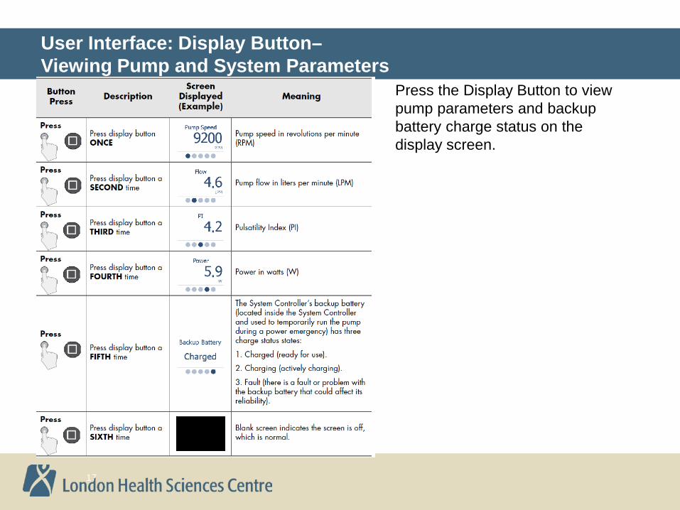
User Interface: Display Button– Viewing Pump and System Parameters
Press the Display Button to view pump parameters and backup battery charge status on the display screen.
17

Advisory & Hazard Alarms
Advisory Alarms (Yellow) • Power Cable Disconnected • Low Voltage • Controller Fault • Backup Battery Fault • Low Speed • Driveline Fault • Backup Battery Not Installed • Controller Clock Not Set
Hazard Alarms (Red) • PUMP OFF • DRIVELINE DISCONNECTED • NO EXTERNAL POWER • LOW FLOW • LOW VOLTAGE

Alarm Guide

Alarm Guide
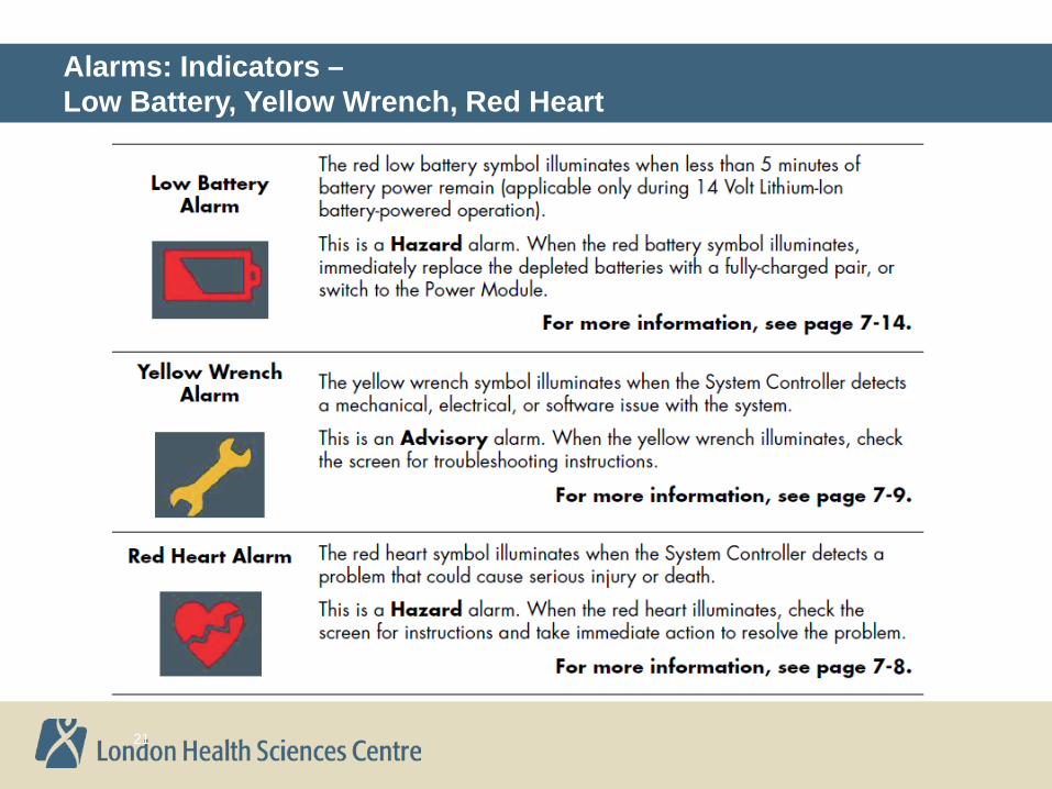
Alarms: Indicators – Low Battery, Yellow Wrench, Red Heart
21

Alarms Indicators: System Controller Cables
22

Alarms: Hazard – Pump Off
1. Check if the fixed speed setting is below 8,000 rpm AND the System Controller’s backup battery is not installed. Under these conditions, the pump can only be started from the System Monitor’s Clinical or Settings screen by pressing the Pump Start button. Otherwise, press any button on the System Controller to attempt pump start.
2. Switch to the backup System Controller and attempt to restart pump. 3. Clinically evaluate patient.
23
System Controller
Screen
Active System Controller
Symbol Alarm Means Alarm Tone Alarm Silence
Alternating
Constant Tone 2 minutes

Alarms: Hazard – Low Flow
1. Ensure that the driveline is connected to System Controller. 2. Ensure that a power source is connected to System Controller. 3. Clinically evaluate patient.
24
System Controller
Screen
Active System Controller
Symbol Alarm Means Alarm Tone Alarm Silence
Constant Tone 2 minutes

Alarms: Hazard – Driveline Disconnected
1. Immediately reconnect the driveline to the System Controller and move the driveline safety tab on the System Controller to the locked position.
2. If alarm persists after reconnecting the driveline, press any button on the System Controller to attempt pump start. Otherwise, check if the fixed speed setting is below 8,000 rpm AND the System Controller’s backup battery is not installed. Under these conditions, the pump can only be started from the System Monitor’s Clinical or Settings screen by pressing the Pump Start button.
3. If driveline is connected and alarm persists, replace the System Controller with a programmed backup System Controller.
25
System Controller
Screen
Active System Controller
Symbol Alarm Means Alarm Tone Alarm Silence
Constant Tone 2 minutes
Important! If controller stops alarming Connect Driveline, but Low Speed and Low Flow alarms persist and the pump does not ramp up to the set speed, disconnect and reconnect the driveline.

Alarms: Hazard – No External Power
• Immediately connect to a working power source
26
System Controller
Screen
Active System Controller
Symbol Alarm Means Alarm Tone Alarm Silence
Constant Tone 2 minutes

Alarms: Hazard – Low Battery
• Refers to external power source • Immediately connect to a working power source
27
System Controller
Screen
Active System Controller
Symbol Alarm Means Alarm Tone Alarm Silence
Constant Tone 2 minutes

Alarms: Advisory – Power Cable Disconnect
• Promptly connect the disconnected power cable
28
System Controller
Screen
Active System Controller
Symbol Alarm Means Alarm Tone Alarm Silence
Fast Beep 2 minutes

Alarms: Advisory – Low Battery
• Refers to external power source • Promptly connect to a working or different power source
29
System Controller
Screen
Active System Controller
Symbol Alarm Means Alarm Tone Alarm Silence
Slow Beep 5 minutes

Alarms: Advisory – System Controller Hardware Fault 1
Controller is operating on primary system. 1. Switch to Backup System Controller 2. Provide patient with a new System Controller
System Controller
Screen
Active System Controller
Symbol Alarm Means Alarm Tone Alarm Silence
Slow Beep 4 hours
30
Note: If LED display is affected, only “Replace Controller ,Controller Fault” will be displayed. Visual indicators and audio tones for other alarms will occur as normal. Pump parameters and alarm history cannot be viewed.
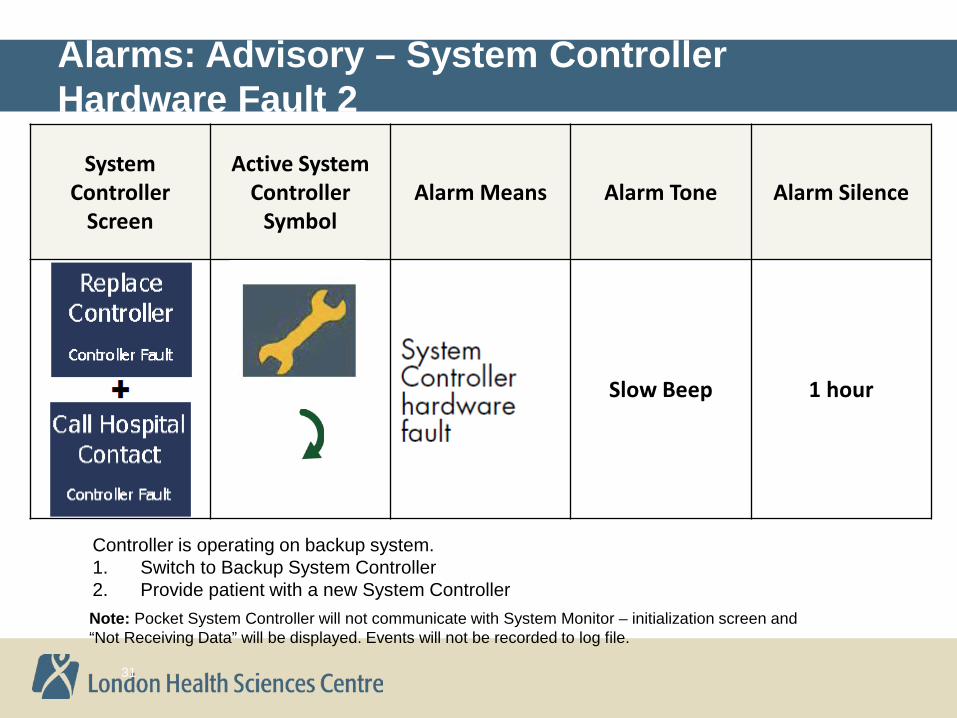
Alarms: Advisory – System Controller Hardware Fault 2
Controller is operating on backup system. 1. Switch to Backup System Controller 2. Provide patient with a new System Controller
System Controller
Screen
Active System Controller
Symbol Alarm Means Alarm Tone Alarm Silence
Slow Beep 1 hour
31
Note: Pocket System Controller will not communicate with System Monitor – initialization screen and “Not Receiving Data” will be displayed. Events will not be recorded to log file.

Alarms: Advisory – Backup Battery Fault
• Replace 11V lithium-ion backup battery
32
System Controller
Screen
Active System Controller
Symbol Alarm Means Alarm Tone Alarm Silence
Slow Beep 4 hours

Alarms: Advisory – Low Speed Advisory Warning
1. Use the System Monitor to check that the fixed speed and low speed limits have been set appropriately
2. Replace system controller 3. Clinically evaluate patient
33
System Controller
Screen
Active System Controller
Symbol Alarm Means Alarm Tone Alarm Silence
Slow Beep 4 hours

Advisory Alarms: Driveline Fault
1. Contact Thoratec to determine next best steps 2. Use System Monitor to silence alarm if necessary 3. See the troubleshooting algorithm
34
System Controller
Screen
Active System Controller
Symbol Alarm Means Alarm Tone Alarm Silence
Slow Beep 4 hours
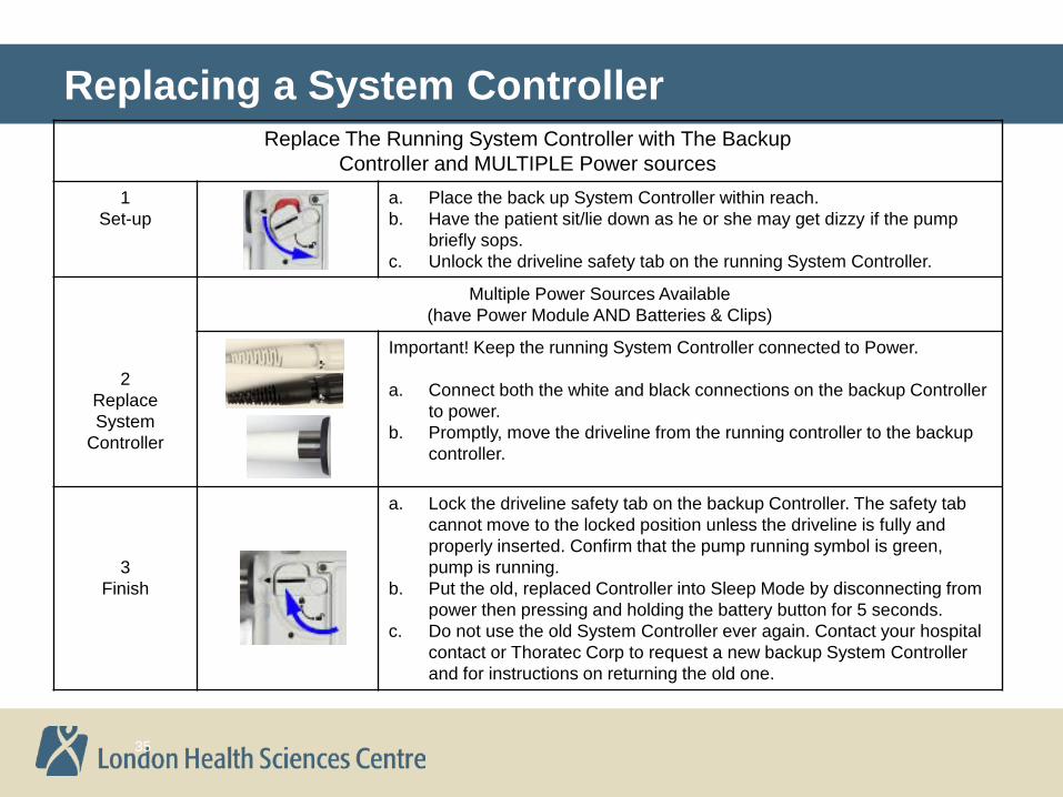
Replacing a System Controller
35
Replace The Running System Controller with The Backup Controller and MULTIPLE Power sources
1 Set-up
a. Place the back up System Controller within reach. b. Have the patient sit/lie down as he or she may get dizzy if the pump
briefly sops. c. Unlock the driveline safety tab on the running System Controller.
2 Replace System
Controller
Multiple Power Sources Available (have Power Module AND Batteries & Clips)
Important! Keep the running System Controller connected to Power.
a. Connect both the white and black connections on the backup Controller to power.
b. Promptly, move the driveline from the running controller to the backup controller.
3 Finish
a. Lock the driveline safety tab on the backup Controller. The safety tab cannot move to the locked position unless the driveline is fully and properly inserted. Confirm that the pump running symbol is green, pump is running.
b. Put the old, replaced Controller into Sleep Mode by disconnecting from power then pressing and holding the battery button for 5 seconds.
c. Do not use the old System Controller ever again. Contact your hospital contact or Thoratec Corp to request a new backup System Controller and for instructions on returning the old one.

Connections: Driveline and Power
Controller always connected to two power connections-AC power or 2 Batteries
Driveline connection

Backup Equipment
Ensure backup controller and extra batteries accompany patient during transport. If possible bring power module with cables and battery charger
Backup controller and batteries in carrying bag
Battery charger
Power Module

HeartWare® Controller Display
Scroll Button
Alarm Mute Button
AC/DC Indicator
Battery Indicator 1
Alarm Indicator
Battery Indicator 2
Controller Display
Power Source 2 Power Source 1

HeartWare® Controller: Alarm Indicator & Mute Button
Alarm Indicator Symbol
• Low Priority Alarms:
• Medium Priority Alarms:
• High Priority Alarms: Alarm Mute Button

Alarm Type Alarm Display (line 1)
Action (line 2)
Low (Solid Yellow)
Low Battery 1 Replace Battery 1
Low Battery 2 Replace Battery 2
Power Disconnect Reconnect Power 1
Power Disconnect Reconnect Power 2
Low Priority Alarms

Medium Priority Alarms
Alarm Type Alarm Display (line 1)
Action (line 2)
Medium (Flashing Yellow)
Controller Fault Call
Controller Fault Call: ALARMS OFF
High Watts Call
Electrical Fault Call
Low Flow Call
Suction Call

High Priority Alarms
Alarm Type Alarm Display (line 1)
Action (line 2)
High – Critical (Blank Display)
No Message No Message
High – Critical (Flashing Red)
VAD Stopped Connect Driveline
VAD Stopped Change Controller
Critical Battery 1 Replace Battery 1
Critical Battery 2 Replace Battery 2
Controller Failed Change Controller

Alarm Display (line 1)
Action (line 2)
Potential Causes
Potential Actions
No Message No Message
• No power to pump
• Pump has stopped
1. Connect two new power sources
2. Replace controller
3. Contact Clinical Specialist
High Priority Alarms: Blank Display
No Power (no message): If both power sources are disconnected from the controller, a loud continuous alarm will sound and there will be NO message on the controller display. The HVAD® Pump is NOT pumping and power sources should be connected immediately. If this action does not resolve the alarm condition, replace the controller.

Alarm Display (line 1)
Action (line 2)
Potential Causes
Potential Actions
VAD Stopped Connect Driveline
• Driveline disconnect
• Driveline fracture
• Connector malfunction/breakage
• VAD electrical failure
1. Reconnect driveline
2. Download and email patient log files
3. Contact clinical specialist
VAD Stopped Change Controller
• Controller failure
• VAD failure
• VAD thrombus or other materials in device
1. Exchange controller
2. Download and email patient log files
3. Contact Clinical Specialist
High Priority Alarms: VAD Stopped

Alarm Display (line 1)
Action (line 2)
Potential Causes
Potential Actions
Controller Failed
Change Controller
• Controller component failed 1. Exchange controller
Critical Battery 1
Replace Battery 1
• Limited battery 1 or battery 2 time remaining
• Critical battery malfunction without adequate secondary power source
1. Replace critical battery with fully charged battery or AC/DC adapter
2. Change controller if new power sources do not correct alarm Critical
Battery 2 Replace
Battery 2
High Priority Alarms: Controller Failed, Critical Battery

1. Have the patient sit or lie down. 2. Place the new controller within easy reach. 3. Connect back-up power sources to the new controller.
– Confirm that the power cables are properly locked on the controller by gently pulling on the cable near the connector
– A “Power Disconnect” alarm will activate if a second power source is not connected to the new controller within 20 seconds of controller power up
– A “VAD Stopped” alarm will activate if the pump driveline is not connected to the new controller within 10 seconds – this alarm will resolve once the pump driveline is connected
Handling an Emergency: Changing the Controller
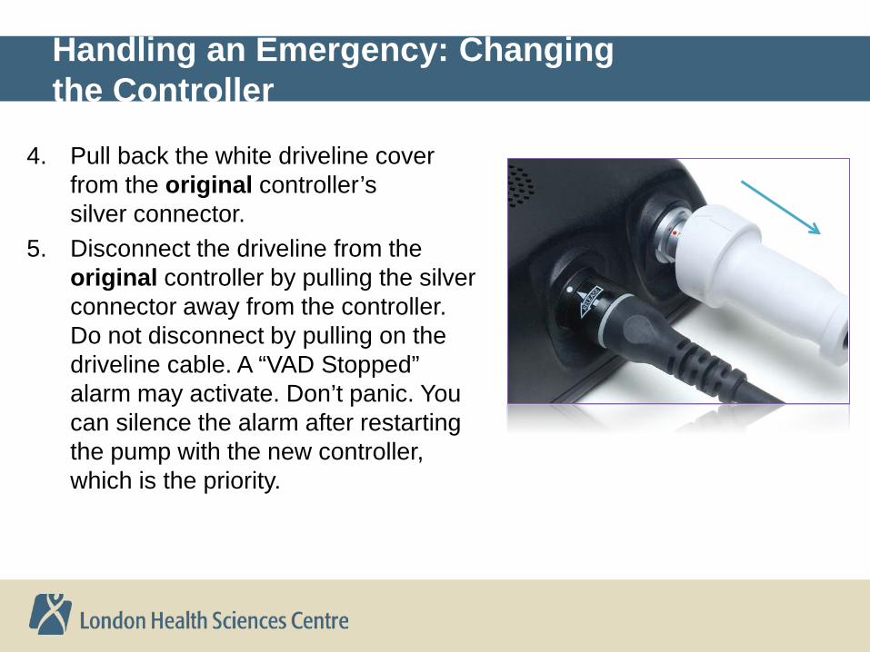
4. Pull back the white driveline cover from the original controller’s silver connector.
5. Disconnect the driveline from the original controller by pulling the silver connector away from the controller. Do not disconnect by pulling on the driveline cable. A “VAD Stopped” alarm may activate. Don’t panic. You can silence the alarm after restarting the pump with the new controller, which is the priority.
Handling an Emergency: Changing the Controller

6. Connect the driveline to the new controller (align the two red marks and push together). If the “VAD Stopped” alarm was active on the new controller, it will now resolve. The pump should restart.
Handling an Emergency: Changing the Controller
Verify the pump is working (RPM, L/min, Watts). If the pump does not restart, call for medical assistance immediately.

7. To prevent the controller alarm from sounding after the power is removed: – If the red alarm adapter is available:
before you remove power, insert it into the blue connector on the original controller.
– If no alarm adapter is available: • Before you remove power,
press and hold the alarm mute and scroll buttons simultaneously on the original controller until it beeps, or for at least 5 seconds
• Release the alarm mute and scroll buttons
Handling an Emergency: Changing the Controller
Original controller

• Connectors for the power sources were designed to both provide power and to be securely locked once connected to the controller
• Forcing connectors together may damage the pins. • To prevent damage: 1) Grasp the back of the connector, 2)
Align solid white arrow and white dot, 3) Gently push (DO NOT twist) until connector naturally locks in place
Connections: Driveline and Power
Power Source Connector with Pins
Controller Connector for Power Sources
• Driveline connection is secured with a collar lock. Grasp ridged portion of silver collar and pull back
• White driveline cover prevents accidental removal

Backup Equipment
Ensure backup controller and extra batteries accompany patient during transport. If possible bring AC power adapter and battery charger
Backup controller and batteries in carrying bag
AC power adapter
Battery charger

EMS assessment protocol: Heartmate 2
LVAD Functioning? Auscultate left upper abdominal quadrant.
Continuous Humming sound = pump IS working. Green double arrows illuminated
on controller-if yes, pump is working ATTENTION: Non-pulsatile pump function.
Patient may not have a palpable pulse or measurable BP or pulse oximeter readings
even if pump is working Patient Stable
Patient Unstable
Treat per Standard Protocols
TRANSPORT URGENTLY TO ER If possible, transport to Implant Centre
Other General Medical Problem
Cardiac Issue/Abnormal
EKG
Treat per ACLS protocol
CPR as necessary
Defibrillation OK
YES, Assess patient
NO
Pump connected to controller? AND Controller connected to power? AND NO Active alarm on controller
YES to all, Assess patient, treat for cardiogenic shock
NO to one or more: Next page
Patient backup controller and extra batteries MUST accompany patient in transit
Implant Centre: LHSC 519-685-8500 pager 1LVAD (15823) to page Dr. Nagpal or VAD Coordinator

EMS assessment protocol: Heartmate 2
TRANSPORT URGENTLY TO ER
If possible, transport to Implant Centre
Length of time that pump has been stopped is
known AND this time less than 5 minutes
Give Heparin 5000u IV STAT Connect controller to pump and/or Connect controller to power and/or Change controller (only if instructed)
LVAD Functioning? Auscultate left upper abdominal quadrant.
Continuous Humming sound = pump IS working. Green double arrows illuminated
on controller-if yes, pump is working ATTENTION: Non-pulsatile pump function.
Patient may not have a palpable pulse or measurable BP or pulse oximeter readings
even if pump is working
Give Heparin 5000u IV STAT (if not given already) Treat for cardiogenic shock DO NOT RESTART
PUMP
NO
YES
YES: Assess/stabilize NO
Patient backup controller and extra batteries MUST
accompany patient in transit
Implant Centre: LHSC 519-685-8500 pager 1LVAD (15823) to page Dr. Nagpal or VAD Coordinator

Resources
• Questions or concerns, contact LHSC VAD team • 519-685-8500 pager 1LVAD (15823) • Dr. D. Nagpal 519-685-8500 x38822 • G. Fisher, VAD coordinator 519-685-8500 x33760 • On the internet: Thoratec Corporation website http://www.thoratec.com/medical-professionals/resource-library/ifus-manuals/heartmate-ll-lvad.aspx