Embed Size (px)
Citation preview
Head-On Impact Deflection of NEAs:
A Case Study for 99942 Apophis
Bernd Dachwald∗ and Ralph Kahle†
German Aerospace Center (DLR), 82234 Wessling, Germany
Bong Wie‡
Arizona State University, Tempe, AZ 85287, USA
Near-Earth asteroid (NEA) 99942 Apophis provides a typical example for the evolutionof asteroid orbits that lead to Earth-impacts after a close Earth-encounter that results in aresonant return. Apophis will have a close Earth-encounter in 2029 with potential very closesubsequent Earth-encounters (or even an impact) in 2036 or later, depending on whetherit passes through one of several less than 1 km-sized gravitational keyholes during its 2029-encounter. A pre-2029 kinetic impact is a very favorable option to nudge the asteroidout of a keyhole. The highest impact velocity and thus deflection can be achieved froma trajectory that is retrograde to Apophis orbit. With a chemical or electric propulsionsystem, however, many gravity assists and thus a long time is required to achieve this. Weshow in this paper that the solar sail might be the better propulsion system for such amission: a solar sail Kinetic Energy Impactor (KEI) spacecraft could impact Apophis froma retrograde trajectory with a very high relative velocity (75-80 km/s) during one of itsperihelion passages. The spacecraft consists of a 160m × 160m, 168 kg solar sail assemblyand a 150 kg impactor. Although conventional spacecraft can also achieve the requiredminimum deflection of 1 km for this approx. 320m-sized object from a prograde trajectory,our solar sail KEI concept also allows the deflection of larger objects. For a launch in 2020,we also show that, even after Apophis has flown through one of the gravitational keyholesin 2029, the solar sail KEI concept is still feasible to prevent Apophis from impacting theEarth, but many KEIs would be required for consecutive impacts to increase the totalEarth-miss distance to a safe value.
I. Introduction
In June 2004, a NEA with a diameter of about 320 m was discovered, which will have a very close encounterwith Earth on 13 Apr 2029 and, with a non-negligible probability, subsequent very close encounters or evenan impact on 13Apr 2036, 13Apr 2037, or later (Refs. 1, 2, and 3). This NEA first got the provisionaldesignation 2004MN4 and later 99942 Apophis. The currently estimated probability that Apophis impactsthe Earth is 1/45 000 for a 2036-encounter and 1/12 346 000 for a 2037-encounter (Ref. 2, October 2006).Note that the current probability of a catastrophic impact in 2036 is higher than, e.g., the probability for anairplane to crash during a flight. Apophis would impact the Earth with a velocity of about 12.6 km/s andthe released energy would equal about 875 Megatons of TNT (Ref. 2). Whether or not Apophis will impactthe Earth in 2036 or 2037 will be decided by its close encounter in 2029. If the asteroid passes through oneof several so-called “gravitational keyholes”, it will get into a resonant orbit and impact the Earth in one ofits later encounters, if no counter-measures are taken.
Apophis’ size (H = 19.2) and taxonomic type are not definitely known at this time (Ref. 2). Accordingto Ref. 1, e.g., Apophis has a diameter of 430 − 970 m. In accordance with Ref. 2, however, we assume for
∗Scientist, German Space Operations Center, Mission Operations Section, Oberpfaffenhofen, [email protected], +49-8153-28 2772, Member AIAA, Member AAS.
†Scientist, German Space Operations Center, Space Flight Technology Section, Oberpfaffenhofen, [email protected], +49-8153-28 2451.
‡Professor, Dept. of Mechanical & Aerospace Engineering, [email protected], +1-480-965 8674, Associate Fellow AIAA.
1 of 12
American Institute of Aeronautics and Astronautics
Planetary Defense Conference 2007, Wahington D.C., USA, 05-08 March 2007(c) 2007 by the authors
our calculations that it is a spherical 320m diameter asteroid with a typical S-class density of 2 720 kg/m3
and thus an estimated mass of 4.67× 10¹⁰ kg.During November and December 2005, ESA’s Advanced Concepts Team (ACT) has organized the 1st
Global Trajectory Optimisation Competition. The goal was to find the trajectory that yields the maximumdeflection of asteroid 2001 TW229 using a nuclear-electric propulsion (NEP) system within a maximummission duration of 30 years. The winning trajectory came from JPL’s Outer Planets Mission AnalysisGroup (Ref. 4). An even improved post-competition trajectory that will be published in Ref. 4 uses an Earth-Venus-Venus-Earth-Earth-Venus-Venus-Earth-Venus-Earth-Jupiter-Saturn-Jupiter gravity assist to make thetrajectory retrograde and impact the target at one of its perihelion passages. The flight time is 28.4 yearsand the used propellant mass is only 3% of the launch mass. Therefore, a similar trajectory would also befeasible for a chemically propelled spacecraft. Although the trajectory for such a mission concept was notyet calculated for Apophis, the flight times for achieving a retrograde orbit would be in the same order asfor the ACT competition problem. This renders chemical and electrical propulsion systems prohibitive forpropelling a retrograde deflection mission to impact Apophis before the close Earth-encounter in 2029 oreven before the potential Earth-impact in 2036.
The solar sail might be the better propulsion system for such a mission. The use of solar sails to achieveimpacts from retrograde orbits was first proposed (and elaborated in a more general way) by McInnes inRefs. 5 and 6. Wie employed in Refs. 7 and 8 the same idea for a fictional asteroid deflection problem byAIAA and made a preliminary conceptual mission design. In Refs. 9 and 10, Dachwald and Wie made amore rigorous trajectory optimization study for this fictional AIAA mission scenario. The results in Refs. 9and 10 show that solar sail Kinetic Energy Impactor (KEI) spacecraft that impact the asteroid with veryhigh relative velocity from a retrograde trajectory are a realistic option for mitigating the impact threat fromNEAs. This paper is about the application of the solar sail KEI concept to remove the real threat from thisreal asteroid.
II. Asteroid Deflection Using Kinetic Energy Impacts
The simplest approach to deflect a NEO is to impact it with a massive projectile at a high relativevelocity. The highest impact velocity can be achieved from a trajectory that is retrograde to the target’sorbit, impacting it during one of its perihelion passages. The change in the object’s Earth-miss distance dueto the impact depends on the time between the KEI’s impact and the object’s Earth impact, i.e. the leadtime ∆tL, and the velocity change ∆v of the asteroid caused by the impactor. In rough terms, the KEI’simpact causes an along-track position shift of (see Refs. 3 and 11)
∆x = 3∆tL∆v (1)
Thus a (typical) ∆v of 0.25 mm/s provides a ∆x of about 24 km in 1 year.A successful asteroid deflection mission will require accurate modeling and prediction of the velocity
change caused by the impactor. The effective impulse imparted to the asteroid will be the sum of the purekinetic impulse (linear momentum) of the impactor plus the impulse due to the “thrust” of material beingejected from the impact crater. The last term can be very significant (even dominant), but its magnitudedepends strongly upon the density, yield strength, and porosity of the material of which the asteroid iscomposed, as well as the mass and relative velocity of the impactor. For example, a head-on collision (at atypical relative velocity of vimp = 75 km/s) of a 150 kg impactor on a 4.67 × 10¹⁰ kg asteroid yields a purekinetic-impact ∆v of approx. 0.24 mm/s. If the asteroid was composed of hard rock, the modeling of craterejecta impulse from previous studies by Ahrens and Harris in Ref. 11 would predict an additional ∆v of0.25 mm/s, which yields an “enhancement factor” of about ξ ≈ 2. If the asteroid was composed of soft rock,the previous studies would predict an even larger additional ∆v of 0.67 mm/s, which yields ξ ≈ 3.8. Morerecent studies by Holsapple in Ref. 12 also indicate ξ ≈ 4 for a non-porous asteroid, while it might be as lowas ξ ≈ 1.16 for a porous asteroid, like asteroid 25143 Itokawa, the target of the Hayabusa mission (Ref. 13).In any case, those values are associated with a large uncertainty. An accurate modeling and prediction of theejecta impulse for various asteroid compositions is therefore a critical part of any kinetic-impact approach.To be on the safe side, we assume the worst case, ξ = 1.16, which gives
∆v = ξmKEI
mApophisvimp = 3.73× 10⁻⁹vimp (2)
2 of 12
American Institute of Aeronautics and Astronautics
Planetary Defense Conference 2007, Wahington D.C., USA, 05-08 March 2007(c) 2007 by the authors
Another practical concern of any kinetic-impact approach is the risk that the impact could result in thefragmentation of the asteroid, which could substantially increase the damage upon Earth impact (Ref. 14).The energy required to fragment an asteroid depends upon its composition and structure. For example, thespecific disruption energy for ice is about 9 J/kg (Ref. 15). Hence the disruption energy for a 320 m-diameterasteroid composed largely of ice (density 917 kg/m3, Ref. 16) is approximately 1.4 × 10¹¹ J. Because thekinetic energy of a 150 kg impactor at a typical relative velocity of 75 km/s would be 4.2 × 10¹¹ J, the iceasteroid would likely fragment. If the asteroid was composed largely of silicates, it would have a disruptionenergy of approximately 9.3 × 10¹² J (the specific disruption energy of silicates is about 200 J/kg, Ref. 15),which is much larger than the kinetic energy delivered by the impactor; such an asteroid would likely stayintact. Therefore, further studies are needed to optimize impactor size, relative impact velocity, and thetotal number of impactors as functions of the asteroid’s size and composition, to ensure that the target willnot be fragmented.
III. Scenario
To demonstrate the different possibilities that solar sails offer for mitigating the impact threat fromNEOs, we assume the following fictive scenario:
1. During the very favorable radar and optical observations in 2013 (see Ref. 3), it is found that Apophisis likely to fly through the gravitational 2036-keyhole in its 2029-encounter and thus have a resonantreturn to hit the Earth in 2036.
2. At 01 Jan 2020, a solar sail KEI that consists of a 160 m × 160 m, 168 kg solar sail assembly and a150 kg impactor is launched from Earth (inserted with zero hyperbolic excess energy, C3 = 0km2/s2).It has a characteristic acceleration (maximum acceleration at 1 AU solar distance) of ac = 0.5 mm/s2.The solar sail film temperature limit is Tlim = 240C.
3. After having attained a trajectory that is retrograde to Apophis’ orbit, the targeting of the asteroidbegins. The solar sail KEI is brought onto a collision trajectory, from where it can impact Apophison 02 Jan 2026 in the case that Apophis is still likely to fly through the keyhole in 2029. Two kinds ofcollision trajectories are investigated, a trajectory that maximizes vimp and an exactly retrograde orbit(ERO) that encounters Apophis at every perihelion and aphelion passage. For steps 4-6, the formercollision trajectory will be assumed.
4. For comparison with the pre-2029-encounter scenario: the mission is aborted before the 2029-encounterbecause it is found that Apophis is not likely anymore to fly through the keyhole. The impact on02 Jan 2026 is changed into a close flyby. Instead of aborting the mission, however, the solar sail KEIis brought to a trajectory that maximizes the deflection for a post-2029-encounter impact, for the casethat this might be necessary. Note that Apophis’ post-encounter orbit is not exactly known at thattime, but the worst case orbit (leading to a close encounter in 2036) can be estimated with sufficientaccuracy.
5. After the close Earth-encounter on 13Apr 2029 it is found that Apophis really flew through the 2036-keyhole and thus has a resonant return to hit the Earth on 13Apr 2036.
6. The solar sail KEI impacts the asteroid shortly after the 2029-encounter on 11 Jun 2029.
6b. Alternatively, for comparison, after its launch on 01 Jan 2020, the solar sail KEI is directly sent onto acollision trajectory that maximizes vimp on 11 Jun 2029.
Because of its large ∆V -capability, a solar sailcraft with a relatively modest characteristic accelerationof 0.5 mm/s2 can achieve a trajectory that is retrograde to Apophis’ orbit within 4.4 years. After thetrajectory is made retrograde to Apophis’ orbit, the KEI is brought onto a collision trajectory, so thatit impacts Apophis with a large head-on velocity at its perihelion of 0.746 AU (where the impact is mosteffective). Such a head-on collision yields an impact velocity in the order of 75 − 80 km/s, which is muchlarger than the typical impact velocity of about 10 km/s of prograde missions such as NASA’s Deep Impactmission (Refs. 17 and 18) or ESA’s projected Don Quijote mission (Ref. 19). For the small Apophis target,the impactor is to be separated from the solar sail prior to the impact because of the extremely demanding
3 of 12
American Institute of Aeronautics and Astronautics
Planetary Defense Conference 2007, Wahington D.C., USA, 05-08 March 2007(c) 2007 by the authors
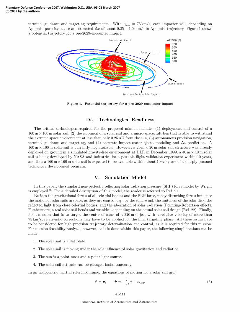
terminal guidance and targeting requirements. With vimp ≈ 75 km/s, each impactor will, depending onApophis’ porosity, cause an estimated ∆v of about 0.25− 1.0 mm/s in Apophis’ trajectory. Figure 1 showsa potential trajectory for a pre-2029-encounter impact.
Y
X
Z
Y
X
Z
520500450400350300
Sail Temp. [K]
Apophis orbit
Earth orbit
Launch at Earth
Retrograde Apophis impact
Figure 1. Potential trajectory for a pre-2029-encounter impact
IV. Technological Readiness
The critical technologies required for the proposed mission include: (1) deployment and control of a160 m× 160 m solar sail, (2) development of a solar sail and a micro-spacecraft bus that is able to withstandthe extreme space environment at less than only 0.25 AU from the sun, (3) autonomous precision navigation,terminal guidance and targeting, and (4) accurate impact-crater ejecta modeling and ∆v-prediction. A160 m × 160 m solar sail is currently not available. However, a 20 m × 20 m solar sail structure was alreadydeployed on ground in a simulated gravity-free environment at DLR in December 1999, a 40 m× 40 m solarsail is being developed by NASA and industries for a possible flight-validation experiment within 10 years,and thus a 160 m×160 m solar sail is expected to be available within about 10–20 years of a sharply pursuedtechnology development program.
V. Simulation Model
In this paper, the standard non-perfectly reflecting solar radiation pressure (SRP) force model by Wrightis employed.20 For a detailed description of this model, the reader is referred to Ref. 21.
Besides the gravitational forces of all celestial bodies and the SRP force, many disturbing forces influencethe motion of solar sails in space, as they are caused, e.g., by the solar wind, the finiteness of the solar disk, thereflected light from close celestial bodies, and the aberration of solar radiation (Poynting-Robertson effect).Furthermore, a real solar sail bends and wrinkles, depending on the actual solar sail design (Ref. 22). Finally,for a mission that is to target the center of mass of a 320 m-object with a relative velocity of more than75 km/s, relativistic corrections may have to be applied for the final targeting phase. All these issues haveto be considered for high precision trajectory determination and control, as it is required for this mission.For mission feasibility analysis, however, as it is done within this paper, the following simplifications can bemade:
1. The solar sail is a flat plate.
2. The solar sail is moving under the sole influence of solar gravitation and radiation.
3. The sun is a point mass and a point light source.
4. The solar sail attitude can be changed instantaneously.
In an heliocentric inertial reference frame, the equations of motion for a solar sail are:
r = v, v = − µ
r3r + aSRP (3)
4 of 12
American Institute of Aeronautics and Astronautics
Planetary Defense Conference 2007, Wahington D.C., USA, 05-08 March 2007(c) 2007 by the authors
where r is the solar sail position, v is the solar sail velocity, µ is the sun’s gravitational parameter, and aSRP
is the SRP acceleration.
VI. Mission Design
Within this paper, evolutionary neurocontrol (ENC) was used to calculate the trajectories. This methodis based on a combination of artificial neural networks (ANNs) with evolutionary algorithms (EAs). For adescription of this method, the reader is referred to Refs. 23–25. ENC was implemented within a low-thrusttrajectory optimization program called InTrance, which stands for Intelligent Trajectory optimization usingneurocontroller evolution. InTrance is a global trajectory optimization method that requires only the targetbody/state and intervals for the initial conditions as input to find a good solution for the specified problem.It works without an initial guess and does not require the attendance of a trajectory optimization expert.
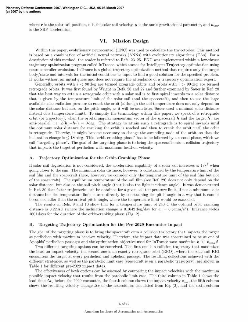
Generally, orbits with i < 90 deg are termed prograde orbits and orbits with i > 90 deg are termedretrograde orbits. It was first found by Wright in Refs. 26 and 27 and further examined by Sauer in Ref. 28that the best way to attain a retrograde orbit with a solar sail is to first spiral inwards to a solar distancethat is given by the temperature limit of the solar sail (and the spacecraft), and then to use the largeavailable solar radiation pressure to crank the orbit (although the sail temperature does not only depend onthe solar distance but also on the pitch angle, as it will be seen later, Sauer used a minimal solar distanceinstead of a temperature limit). To simplify the terminology within this paper, we speak of a retrogradeorbit (or trajectory), when the orbital angular momentum vector of the spacecraft h and the target hT areanti-parallel, i.e. ∠(h,−hT) = 0 deg. The strategy to attain such a retrograde is to spiral inwards untilthe optimum solar distance for cranking the orbit is reached and then to crank the orbit until the orbitis retrograde. Thereby, it might become necessary to change the ascending node of the orbit, so that theinclination change is ≤ 180 deg. This “orbit-cranking phase” has to be followed by a second phase, which wecall “targeting phase”. The goal of the targeting phase is to bring the spacecraft onto a collision trajectorythat impacts the target at perihelion with maximum head-on velocity.
A. Trajectory Optimization for the Orbit-Cranking Phase
If solar sail degradation is not considered, the acceleration capability of a solar sail increases ∝ 1/r2 whengoing closer to the sun. The minimum solar distance, however, is constrained by the temperature limit of thesail film and the spacecraft (here, however, we consider only the temperature limit of the sail film but notof the spacecraft). The equilibrium temperature of the sail film (see Ref. 29) does not only depend on thesolar distance, but also on the sail pitch angle (that is also the light incidence angle). It was demonstratedin Ref. 30 that faster trajectories can be obtained for a given sail temperature limit, if not a minimum solardistance but the temperature limit is used directly by constraining the pitch angle in a way that it cannotbecome smaller than the critical pitch angle, where the temperature limit would be exceeded.
The results in Refs. 9 and 10 show that for a temperature limit of 240C the optimal orbit crankingdistance is 0.22 AU (where the inclination change is 0.1642 deg/day for ac = 0.5 mm/s2). InTrance yields1601 days for the duration of the orbit-cranking phase (Fig. 2).
B. Targeting Trajectory Optimization for the Pre-2029-Encounter Impact
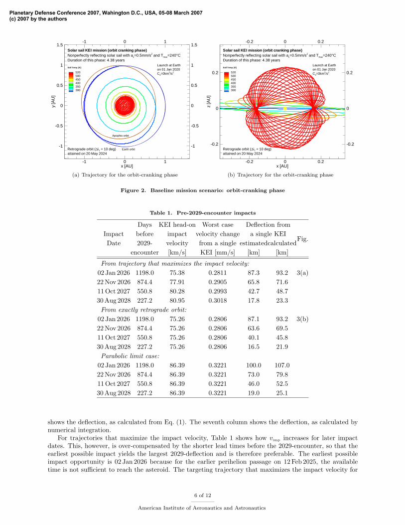
The goal of the targeting phase is to bring the spacecraft onto a collision trajectory that impacts the targetat perihelion with maximum head-on velocity. Therefore, the impact date was constrained to be at one ofApophis’ perihelion passages and the optimization objective used for InTrance was: maximize v · (−vNEA)!
Two different targeting options can be conceived. The first one is a collision trajectory that maximizesthe head-on impact velocity, the second one is an exactly retrograde orbit (ERO), where the solar sail KEIencounters the target at every perihelion and aphelion passage. The resulting deflections achieved with thedifferent strategies, as well as the parabolic limit case (spacecraft is on a parabolic trajectory), are shown inTable 1 for different pre-2029 impact dates.
The effectiveness of both options can be assessed by comparing the impact velocities with the maximumpossible impact velocity that results from the parabolic limit case. The third column in Table 1 shows thelead time ∆tL before the 2029-encounter, the fourth column shows the impact velocity vimp, the fifth columnshows the resulting velocity change ∆v of the asteroid, as calculated from Eq. (2), and the sixth column
5 of 12
American Institute of Aeronautics and Astronautics
Planetary Defense Conference 2007, Wahington D.C., USA, 05-08 March 2007(c) 2007 by the authors
x [AU]
y[A
U]
-1
-1
0
0
1
1
-1 -1
-0.5 -0.5
0 0
0.5 0.5
1 1
1.5 1.5
520500450400350300
Retrograde orbit (ΔiT = 10 deg)attained on 20 May 2024
Sail Temp. [K]
Solar sail KEI mission (orbit cranking phase)
Launch at Earthon 01 Jan 2020C3=0km2/s2
Nonperfectly reflecting solar sail with ac=0.5mm/s2 and Tmax=240°CDuration of this phase: 4.38 years
Apophis orbit
Earth orbit
(a) Trajectory for the orbit-cranking phase
x [AU]
z[A
U]
-0.2
-0.2
0
0
0.2
0.2
-0.2 -0.2
0 0
0.2 0.2520500450400350300
Retrograde orbit (ΔiT = 10 deg)attained on 20 May 2024
Sail Temp. [K]
Solar sail KEI mission (orbit cranking phase)
Launch at Earthon 01 Jan 2020C3=0km2/s2
Nonperfectly reflecting solar sail with ac=0.5mm/s2 and Tmax=240°CDuration of this phase: 4.38 years
(b) Trajectory for the orbit-cranking phase
Figure 2. Baseline mission scenario: orbit-cranking phase
Table 1. Pre-2029-encounter impacts
Days KEI head-on Worst case Deflection fromImpact before impact velocity change a single KEIDate 2029- velocity from a single estimatedcalculated
Fig.
encounter [km/s] KEI [mm/s] [km] [km]
From trajectory that maximizes the impact velocity:02 Jan 2026 1198.0 75.38 0.2811 87.3 93.2 3(a)22 Nov 2026 874.4 77.91 0.2905 65.8 71.611 Oct 2027 550.8 80.28 0.2993 42.7 48.730 Aug 2028 227.2 80.95 0.3018 17.8 23.3From exactly retrograde orbit:
02 Jan 2026 1198.0 75.26 0.2806 87.1 93.2 3(b)22 Nov 2026 874.4 75.26 0.2806 63.6 69.511 Oct 2027 550.8 75.26 0.2806 40.1 45.830 Aug 2028 227.2 75.26 0.2806 16.5 21.9Parabolic limit case:
02 Jan 2026 1198.0 86.39 0.3221 100.0 107.022 Nov 2026 874.4 86.39 0.3221 73.0 79.811 Oct 2027 550.8 86.39 0.3221 46.0 52.530 Aug 2028 227.2 86.39 0.3221 19.0 25.1
shows the deflection, as calculated from Eq. (1). The seventh column shows the deflection, as calculated bynumerical integration.
For trajectories that maximize the impact velocity, Table 1 shows how vimp increases for later impactdates. This, however, is over-compensated by the shorter lead times before the 2029-encounter, so that theearliest possible impact yields the largest 2029-deflection and is therefore preferable. The earliest possibleimpact opportunity is 02 Jan 2026 because for the earlier perihelion passage on 12 Feb 2025, the availabletime is not sufficient to reach the asteroid. The targeting trajectory that maximizes the impact velocity for
6 of 12
American Institute of Aeronautics and Astronautics
Planetary Defense Conference 2007, Wahington D.C., USA, 05-08 March 2007(c) 2007 by the authors
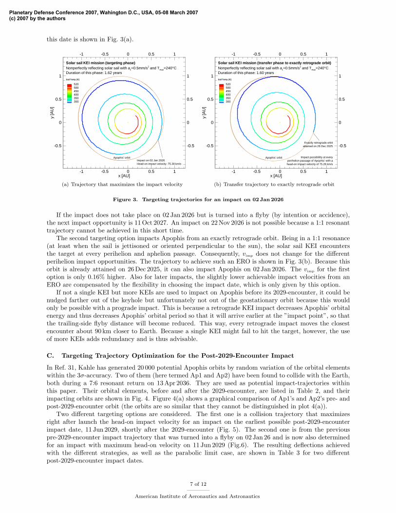
this date is shown in Fig. 3(a).
x [AU]
y[A
U]
-1
-1
-0.5
-0.5
0
0
0.5
0.5
1
1
-0.5 -0.5
0 0
0.5 0.5
1 1
520500450400350300
Sail Temp. [K]
Solar sail KEI mission (targeting phase)Nonperfectly reflecting solar sail with ac=0.5mm/s2 and Tmax=240°CDuration of this phase: 1.62 years
Apophis’ orbitImpact on 02 Jan 2026Head-on impact velocity: 75.38 km/s
(a) Trajectory that maximizes the impact velocity
x [AU]
y[A
U]
-1
-1
-0.5
-0.5
0
0
0.5
0.5
1
1
-0.5 -0.5
0 0
0.5 0.5
1 1
520500450400350300
Sail Temp. [K]
Solar sail KEI mission (transfer phase to exactly retrograde orbit)Nonperfectly reflecting solar sail with ac=0.5mm/s2 and Tmax=240°CDuration of this phase: 1.60 years
Apophis’ orbit
Exactly retrograde orbitattained on 26 Dec 2025
Impact possiblility at everyperihelion passage of Apophis’ with ahead-on impact velocity of 75.26 km/s
(b) Transfer trajectory to exactly retrograde orbit
Figure 3. Targeting trajectories for an impact on 02 Jan 2026
If the impact does not take place on 02 Jan 2026 but is turned into a flyby (by intention or accidence),the next impact opportunity is 11 Oct 2027. An impact on 22 Nov 2026 is not possible because a 1:1 resonanttrajectory cannot be achieved in this short time.
The second targeting option impacts Apophis from an exactly retrograde orbit. Being in a 1:1 resonance(at least when the sail is jettisoned or oriented perpendicular to the sun), the solar sail KEI encountersthe target at every perihelion and aphelion passage. Consequently, vimp does not change for the differentperihelion impact opportunities. The trajectory to achieve such an ERO is shown in Fig. 3(b). Because thisorbit is already attained on 26 Dec 2025, it can also impact Apophis on 02 Jan 2026. The vimp for the firstoption is only 0.16% higher. Also for later impacts, the slightly lower achievable impact velocities from anERO are compensated by the flexibility in choosing the impact date, which is only given by this option.
If not a single KEI but more KEIs are used to impact on Apophis before its 2029-encounter, it could benudged farther out of the keyhole but unfortunately not out of the geostationary orbit because this wouldonly be possible with a prograde impact. This is because a retrograde KEI impact decreases Apophis’ orbitalenergy and thus decreases Apophis’ orbital period so that it will arrive earlier at the ”impact point”, so thatthe trailing-side flyby distance will become reduced. This way, every retrograde impact moves the closestencounter about 90 km closer to Earth. Because a single KEI might fail to hit the target, however, the useof more KEIs adds redundancy and is thus advisable.
C. Targeting Trajectory Optimization for the Post-2029-Encounter Impact
In Ref. 31, Kahle has generated 20 000 potential Apophis orbits by random variation of the orbital elementswithin the 3σ-accuracy. Two of them (here termed Ap1 and Ap2) have been found to collide with the Earth,both during a 7:6 resonant return on 13 Apr 2036. They are used as potential impact-trajectories withinthis paper. Their orbital elements, before and after the 2029-encounter, are listed in Table 2, and theirimpacting orbits are shown in Fig. 4. Figure 4(a) shows a graphical comparison of Ap1’s and Ap2’s pre- andpost-2029-encounter orbit (the orbits are so similar that they cannot be distinguished in plot 4(a)).
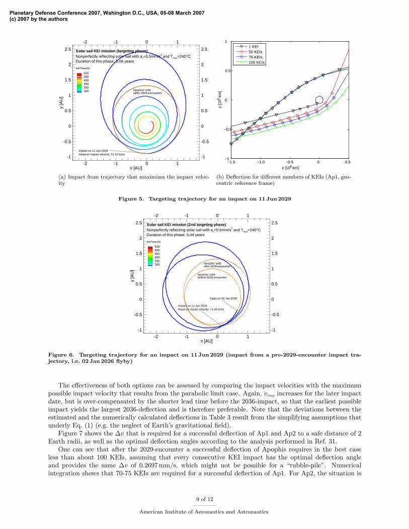
Two different targeting options are considered. The first one is a collision trajectory that maximizesright after launch the head-on impact velocity for an impact on the earliest possible post-2029-encounterimpact date, 11 Jun 2029, shortly after the 2029-encounter (Fig. 5). The second one is from the previouspre-2029-encounter impact trajectory that was turned into a flyby on 02 Jan 26 and is now also determinedfor an impact with maximum head-on velocity on 11 Jun 2029 (Fig.6). The resulting deflections achievedwith the different strategies, as well as the parabolic limit case, are shown in Table 3 for two differentpost-2029-encounter impact dates.
7 of 12
American Institute of Aeronautics and Astronautics
Planetary Defense Conference 2007, Wahington D.C., USA, 05-08 March 2007(c) 2007 by the authors
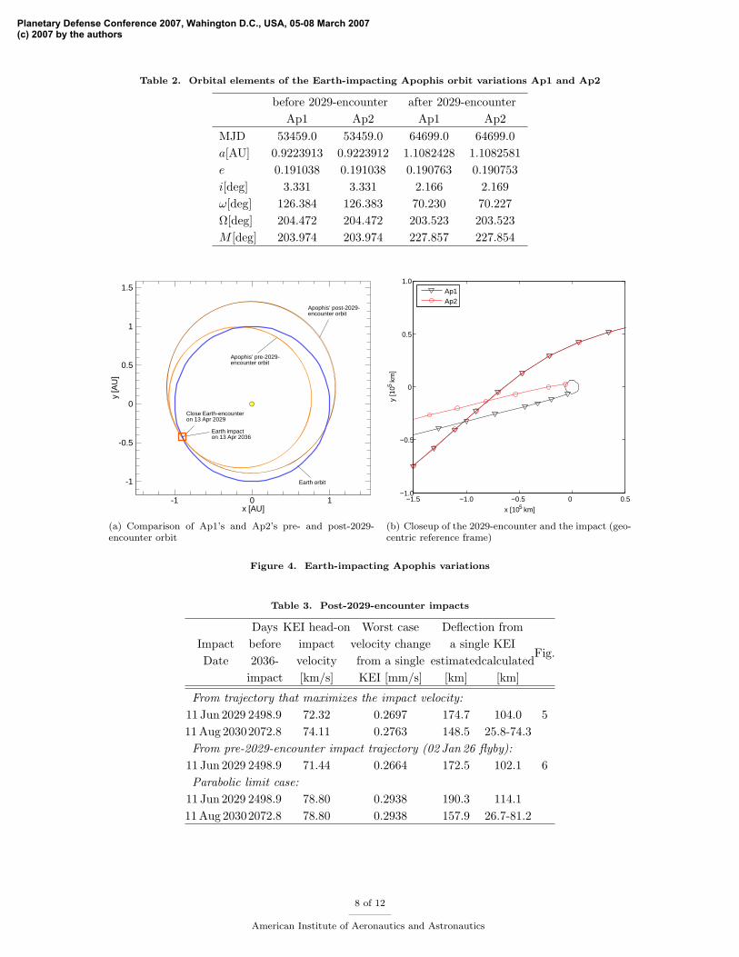
Table 2. Orbital elements of the Earth-impacting Apophis orbit variations Ap1 and Ap2
before 2029-encounter after 2029-encounterAp1 Ap2 Ap1 Ap2
MJD 53459.0 53459.0 64699.0 64699.0a[AU] 0.9223913 0.9223912 1.1082428 1.1082581e 0.191038 0.191038 0.190763 0.190753i[deg] 3.331 3.331 2.166 2.169ω[deg] 126.384 126.383 70.230 70.227Ω[deg] 204.472 204.472 203.523 203.523M [deg] 203.974 203.974 227.857 227.854
x [AU]
y[A
U]
-1 0 1
-1
-0.5
0
0.5
1
1.5
Apophis’ post-2029-encounter orbit
Earth impacton 13 Apr 2036
Apophis’ pre-2029-encounter orbit
Earth orbit
Close Earth-encounteron 13 Apr 2029
(a) Comparison of Ap1’s and Ap2’s pre- and post-2029-encounter orbit
−1.5 −1.0 −0.5 0 0.5−1.0
−0.5
0
0.5
1.0
x [105 km]
y [1
05 km
]
Ap1Ap2
(b) Closeup of the 2029-encounter and the impact (geo-centric reference frame)
Figure 4. Earth-impacting Apophis variations
Table 3. Post-2029-encounter impacts
Days KEI head-on Worst case Deflection fromImpact before impact velocity change a single KEIDate 2036- velocity from a single estimatedcalculated
Fig.
impact [km/s] KEI [mm/s] [km] [km]
From trajectory that maximizes the impact velocity:11 Jun 2029 2498.9 72.32 0.2697 174.7 104.0 511 Aug 20302072.8 74.11 0.2763 148.5 25.8-74.3From pre-2029-encounter impact trajectory (02 Jan 26 flyby):
11 Jun 2029 2498.9 71.44 0.2664 172.5 102.1 6Parabolic limit case:
11 Jun 2029 2498.9 78.80 0.2938 190.3 114.111 Aug 20302072.8 78.80 0.2938 157.9 26.7-81.2
8 of 12
American Institute of Aeronautics and Astronautics
Planetary Defense Conference 2007, Wahington D.C., USA, 05-08 March 2007(c) 2007 by the authors
x [AU]
y[A
U]
-2
-2
-1
-1
0
0
1
1
-1 -1
-0.5 -0.5
0 0
0.5 0.5
1 1
1.5 1.5
2 2
2.5 2.5
520500450400350300
Sail Temp. [K]
Solar sail KEI mission (targeting phase)Nonperfectly reflecting solar sail with ac=0.5mm/s2 and Tmax=240°CDuration of this phase: 5.06 years
Apophis’ orbit(after 2029-encounter)
Impact on 11 Jun 2029Head-on impact velocity: 72.32 km/s
(a) Impact from trajectory that maximizes the impact veloc-ity
−1.5 −1.0 −0.5 0 0.5 −1
−0.5
0
0.5
1
x [105 km]
y [1
05 km
]
1 KEI50 KEIs75 KEIs100 KEIs
(b) Deflection for different numbers of KEIs (Ap1, geo-centric reference frame)
Figure 5. Targeting trajectory for an impact on 11 Jun 2029
x [AU]
y[A
U]
-2
-2
-1
-1
0
0
1
1
-1 -1
-0.5 -0.5
0 0
0.5 0.5
1 1
1.5 1.5
2 2
2.5 2.5
520500450400350300
Sail Temp. [K]
Solar sail KEI mission (2nd targeting phase)
Flyby on 02 Jan 2026
Nonperfectly reflecting solar sail with ac=0.5mm/s2 and Tmax=240°CDuration of this phase: 3.44 years
Apophis’ orbitbefore 2029-encounter
Apophis’ orbitafter 2029-encounter
Impact on 11 Jun 2029Head-on impact velocity: 71.44 km/s
Figure 6. Targeting trajectory for an impact on 11 Jun 2029 (impact from a pre-2029-encounter impact tra-jectory, i.e. 02 Jan 2026 flyby)
The effectiveness of both options can be assessed by comparing the impact velocities with the maximumpossible impact velocity that results from the parabolic limit case. Again, vimp increases for the later impactdate, but is over-compensated by the shorter lead time before the 2036-impact, so that the earliest possibleimpact yields the largest 2036-deflection and is therefore preferable. Note that the deviations between theestimated and the numerically calculated deflections in Table 3 result from the simplifying assumptions thatunderly Eq. (1) (e.g. the neglect of Earth’s gravitational field).
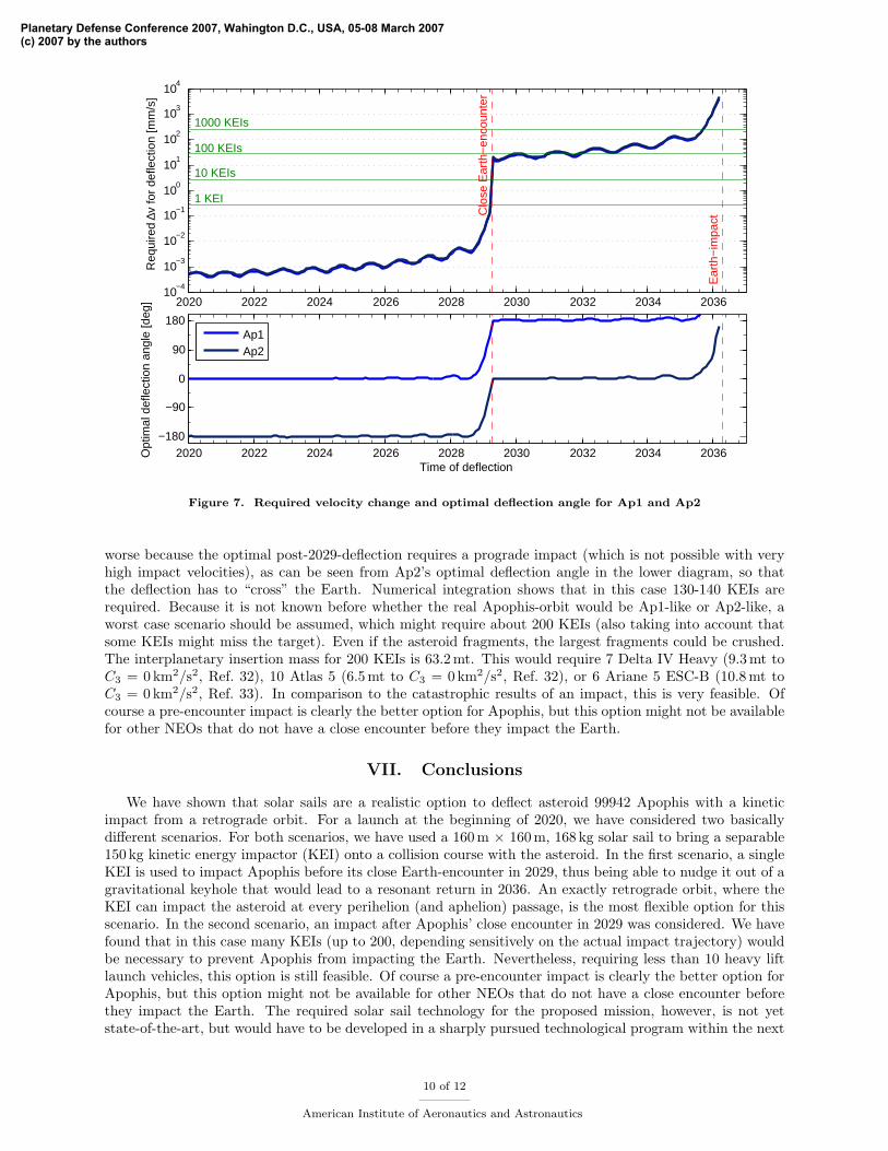
Figure 7 shows the ∆v that is required for a successful deflection of Ap1 and Ap2 to a safe distance of 2Earth radii, as well as the optimal deflection angles according to the analysis performed in Ref. 31.
One can see that after the 2029-encounter a successful deflection of Apophis requires in the best caseless than about 100 KEIs, assuming that every consecutive KEI impact has the optimal deflection angleand provides the same ∆v of 0.2697 mm/s, which might not be possible for a “rubble-pile”. Numericalintegration shows that 70-75 KEIs are required for a successful deflection of Ap1. For Ap2, the situation is
9 of 12
American Institute of Aeronautics and Astronautics
Planetary Defense Conference 2007, Wahington D.C., USA, 05-08 March 2007(c) 2007 by the authors
2020 2022 2024 2026 2028 2030 2032 2034 203610
−4
10−3
10−2
10−1
100
101
102
103
104
1 KEI
10 KEIs
100 KEIs
1000 KEIs
Clo
se E
arth
−en
coun
ter
Ear
th−
impa
ct
Req
uire
d ∆v
for
defle
ctio
n [m
m/s
]
2020 2022 2024 2026 2028 2030 2032 2034 2036−180
−90
0
90
180
Time of deflection
Opt
imal
def
lect
ion
angl
e [d
eg]
Ap1Ap2
Figure 7. Required velocity change and optimal deflection angle for Ap1 and Ap2
worse because the optimal post-2029-deflection requires a prograde impact (which is not possible with veryhigh impact velocities), as can be seen from Ap2’s optimal deflection angle in the lower diagram, so thatthe deflection has to “cross” the Earth. Numerical integration shows that in this case 130-140 KEIs arerequired. Because it is not known before whether the real Apophis-orbit would be Ap1-like or Ap2-like, aworst case scenario should be assumed, which might require about 200 KEIs (also taking into account thatsome KEIs might miss the target). Even if the asteroid fragments, the largest fragments could be crushed.The interplanetary insertion mass for 200 KEIs is 63.2 mt. This would require 7 Delta IV Heavy (9.3 mt toC3 = 0km2/s2, Ref. 32), 10 Atlas 5 (6.5 mt to C3 = 0km2/s2, Ref. 32), or 6 Ariane 5 ESC-B (10.8 mt toC3 = 0 km2/s2, Ref. 33). In comparison to the catastrophic results of an impact, this is very feasible. Ofcourse a pre-encounter impact is clearly the better option for Apophis, but this option might not be availablefor other NEOs that do not have a close encounter before they impact the Earth.
VII. Conclusions
We have shown that solar sails are a realistic option to deflect asteroid 99942 Apophis with a kineticimpact from a retrograde orbit. For a launch at the beginning of 2020, we have considered two basicallydifferent scenarios. For both scenarios, we have used a 160 m × 160 m, 168 kg solar sail to bring a separable150 kg kinetic energy impactor (KEI) onto a collision course with the asteroid. In the first scenario, a singleKEI is used to impact Apophis before its close Earth-encounter in 2029, thus being able to nudge it out of agravitational keyhole that would lead to a resonant return in 2036. An exactly retrograde orbit, where theKEI can impact the asteroid at every perihelion (and aphelion) passage, is the most flexible option for thisscenario. In the second scenario, an impact after Apophis’ close encounter in 2029 was considered. We havefound that in this case many KEIs (up to 200, depending sensitively on the actual impact trajectory) wouldbe necessary to prevent Apophis from impacting the Earth. Nevertheless, requiring less than 10 heavy liftlaunch vehicles, this option is still feasible. Of course a pre-encounter impact is clearly the better option forApophis, but this option might not be available for other NEOs that do not have a close encounter beforethey impact the Earth. The required solar sail technology for the proposed mission, however, is not yetstate-of-the-art, but would have to be developed in a sharply pursued technological program within the next
10 of 12
American Institute of Aeronautics and Astronautics
Planetary Defense Conference 2007, Wahington D.C., USA, 05-08 March 2007(c) 2007 by the authors
10 to 20 years. Other problems that have to be considered for the design of this mission are the extremerequirements for the terminal guidance prior to impact (accuracy much better than 100m at a relativevelocity of more than 75 km/s) and the thermal control that has to make the spacecraft withstand very closesolar distances (0.2− 0.25 AU).
Acknowledgements
The work described in this paper was funded in part by the In-Space Propulsion Technology Program,which is managed by NASA’s Science Mission Directorate in Washington, D.C., and implemented by the In-Space Propulsion Technology Office at Marshall Space Flight Center in Huntsville, Alabama. The programobjective is to develop in-space propulsion technologies that can enable or benefit near and mid-term NASAspace science missions by significantly reducing cost, mass or travel times.
References
1Near Earth Objects Dynamic Site Website, http://newton.dm.unipi.it/cgi-bin/neodys/ neoibo.2NASA’s Near-Earth Object Program Website, http://neo.jpl.nasa.gov.3Chesley, S., “Potential Impact Detection for Near-Earth Asteroids: The Case of 99942 Apophis (2004 MN4),” Asteroids,
Comets, Meteors. Proceedings IAU Symposium No. 229 , edited by S. Ferraz-Mello and D. Lazzaro, Cambridge UniversityPress, Cambridge, New York, Melbourne, 2006.
4Petropoulos, A., Kowalkowski, T., Vavrina, M., Parcher, D., Finlayson, P., Whiffen, G., and Sims, J., “1st ACT GlobalTrajectory Optimisation Competition: Results found at the Jet Propulsion Laboratory,” Acta Astronautica, in press.
5McInnes, C., “Deflection of Near-Earth Asteroids by Kinetic Energy Impacts From Retrograde Orbits,” Planetary andSpace Science, Vol. 52, 2004, pp. 587–590.
6McInnes, C., Hughes, G., and Macdonald, M., “High-Energy Small Body Missions Using Solar Sail Propulsion,” 56th
International Astronautical Congress, Fukuoka, Japan, October 2005, IAC-05-A3.5.B.7Wie, B., “Solar Sailing Kinetic Energy Interceptor (KEI) Mission for Impacting/Deflecting Near-Earth Asteroids,” 41st
AIAA/ASME/SAE/ASEE Joint Propulsion Conference and Exhibit, Tucson, USA, July 2005, AIAA Paper 2005-3725.8Wie, B., “Thrust Vector Control of Solar Sail Spacecraft,” AIAA Guidance, Navigation, and Control Conference, San
Francisco, USA, August 2005, AIAA Paper 2005-6086.9Dachwald, B. and Wie, B., “Solar Sail Trajectory Optimization for Intercepting, Impacting, and Deflecting Near-Earth
Asteroids,” AIAA Guidance, Navigation, and Control Conference, San Francisco, USA, August 2005, AIAA Paper 2005-6176.10Dachwald, B. and Wie, B., “Solar Sail Kinetic Energy Impactor Trajectory Optimization for an Asteroid Deflection
Mission,” Journal of Spacecraft and Rockets, accepted.11Gehrels, T., editor, Deflection and Fragmentation of Near-Earth Asteroids. The University of Arizona Press, Tucson,
USA, 1994.12Holsapple, K., “About Deflecting Asteroids and Comets,” Mitigation of Hazardous Comets and Asteroids, edited by
M. Belton, T. Morgan, N. Samarasinha, and D. Yeomans, Cambridge University Press, Cambridge, New York, Melbourne,2004, pp. 113–140.
13Fujiwara, A., Kawaguchi, J., Yeomans, D., Abe, M., Mukai, T., Okada, T., Saito, J., Yano, H., Yoshikawa, M., Scheeres,D., Barnouin-Iha, O., Cheng, A., Demura, H., Gaskell, R., Hirata, N., Ikeda, H., Kominato, T., Miyamoto, H., Nakamura, A.,Nakamura, R., Sasaki, S., and Uesugi, K., “The Rubble-Pile Asteroid Itokawa as Observed by Hayabusa,” Science, Vol. 312,2006, pp. 1330–1334.
14Housen, R. and Holsapple, K., “Impact Cratering on Porous Asteroids,” Icarus, Vol. 163, 203, pp. 102–119.15Holsapple, K., Giblin, I., Housen, K., Nakamura, A., and Ryan, E., “Asteroid Impacts: Laboratory Experiments and
Scaling Laws,” Asteroids III , edited by W. Bottke, A. Cellino, and P. Paolicchi, Space Science Series, University of ArizonaPress, Tucson, 2002, pp. 443–462.
16Shafer, B., Garcia, M., Scammon, R., Snell, C., Stellingwerf, R., Remo, J., Managan, R., and Rosenkilde, C., “TheCoupling of Energy to Asteroids and Comets,” Hazards Due to Comets and Asteroids, edited by T. Gehrels, The University ofArizona Press, Tucson, USA, 1994, pp. 955–1012.
17Blume, W., “Deep Impact: Mission Design Approach for a New Discovery Mission,” Acta Astronautica, Vol. 52, No. 2-6,2003, pp. 105–110.
18NASA’s Deep Impact Mission Web Site, http://deepimpact.jpl.nasa.gov.19ESA’s Don Quijote Mission Web Site, http://www.esa.int/gsp/NEO/quijote/quijote.htm.20Wright, J., Space Sailing, Gordon and Breach Science Publishers, Philadelphia, 1992.21Dachwald, B., Mengali, G., Quarta, A., and Macdonald, M., “Parametric Model and Optimal Control of Solar Sails with
Optical Degradation,” Journal of Guidance, Control, and Dynamics, Vol. 29, No. 5, 2006, pp. 1170–1178.22Garbe, G., Wie, B., Murphy, D., Ewing, A., Lichodziejewski, L., Derbes, B., Campbell, B., Wang, J., Taleghani, B.,
Canfield, S., Beard, J., and Peddieson, J., “Solar Sail Propulsion Technology Development,” Recent Advances in GossamerSpacecraft , edited by C. Jenkins, Vol. 212 of Progress in Astronautics and Aeronautics, American Institute of Aeronautics andAstronautics, Reston, 2006, pp. 191–261.
23Dachwald, B., Low-Thrust Trajectory Optimization and Interplanetary Mission Analysis Using Evolutionary Neurocon-trol , Doctoral thesis, Universitat der Bundeswehr Munchen; Fakultat fur Luft- und Raumfahrttechnik, 2004.
11 of 12
American Institute of Aeronautics and Astronautics
Planetary Defense Conference 2007, Wahington D.C., USA, 05-08 March 2007(c) 2007 by the authors
24Dachwald, B., “Optimization of Interplanetary Solar Sailcraft Trajectories Using Evolutionary Neurocontrol,” Journal ofGuidance, Control, and Dynamics, Vol. 27, No. 1, pp. 66–72.
25Dachwald, B., “Optimization of Very-Low-Thrust Trajectories Using Evolutionary Neurocontrol,” Acta Astronautica,Vol. 57, No. 2-8, 2005, pp. 175–185.
26Wright, J., “Solar Sailing – Evaluation of Concept and Potential,” Tech. rep., Battelle Columbus Laboratories, Columbus,Ohio, March 1976, BMI-NLVP-TM-74-3.
27Wright, J. and Warmke, J., “Solar Sail Mission Applications,” AIAA/AAS Astrodynamics Conference, San Diego, USA,August 18-20, 1976, AIAA Paper 76-808.
28Sauer, C., “A Comparison of Solar Sail and Ion Drive Trajectories for a Halley’s Comet Rendezvous Mission,” AAS/AIAAAstrodynamics Conference, Jackson, USA, September 1977, AAS Paper 77-104.
29McInnes, C., Solar Sailing. Technology, Dynamics and Mission Applications, Springer–Praxis Series in Space Scienceand Technology, Springer–Praxis, Berlin, Heidelberg, New York, Chicester, 1999.
30Dachwald, B., “Optimal Solar Sail Trajectories for Missions to the Outer Solar System,” Journal of Guidance, Control,and Dynamics, Vol. 28, No. 6, 2005, pp. 1187–1193.
31Kahle, R., Hahn, G., and Kuhrt, E., “Optimal Deflection of NEOs en Route of Collision with the Earth,” Icarus, Vol. 182,2006, pp. 482–488.
32Isakowitz, S., Hopkins, J., and Hopkins Jr., J., International Reference Guide to Space Launch Systems, AmericanInstitute of Aeronautics and Astronautics, Reston, 4th ed., 2004.
33Ancarola, B., “Ariane 5 Performance Optimisation for Interplanetary Missions,” AIAA/AAS Astrodynamics SpecialistConference, Monterey, USA, August 2002, AIAA Paper 2002-4902.
12 of 12
American Institute of Aeronautics and Astronautics
Planetary Defense Conference 2007, Wahington D.C., USA, 05-08 March 2007(c) 2007 by the authors