Embed Size (px)
Citation preview

Tatiana Antysheva,
Head of Strategic Growth Group
Stepan Borovitskiy,
Chief specialist, Reactor Unit Design Group
8 July 2011

Reactor design introduction
Nuclear steam supply system
Safety concept
Design/Safety Implications from the
Fukushima Event
Design certification and deployment schedule
SVBR-100 Reactor Modules
2

Reactor Design Introduction
3
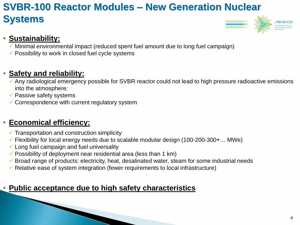
• Sustainability: Minimal environmental impact (reduced spent fuel amount due to long fuel campaign)
Possibility to work in closed fuel cycle systems
• Safety and reliability: Any radiological emergency possible for SVBR reactor could not lead to high pressure radioactive emissions
into the atmosphere:
Passive safety systems
Correspondence with current regulatory system
• Economical efficiency:
Transportation and construction simplicity
Flexibility for local energy needs due to scalable modular design (100-200-300+… MWe)
Long fuel campaign and fuel universality
Possibility of deployment near residential area (less than 1 km)
Broad range of products: electricity, heat, desalinated water, steam for some industrial needs
Relative ease of system integration (fewer requirements to local infrastructure)
• Public acceptance due to high safety characteristics
SVBR-100 Reactor Modules – New Generation Nuclear
Systems
4

• Operational experience:
80 reactor years of experience on Russian submarines (Alpha class)
• Prototype research facilities:
Test prototype 27/VT: more than 50 years of experience
Test prototype KM-1
• R&D program to support reactor design includes about 20 test facilities
(both existing, modernized and new ones) (6 russian research institutes
involved)
Historical Technical Basis
5
6
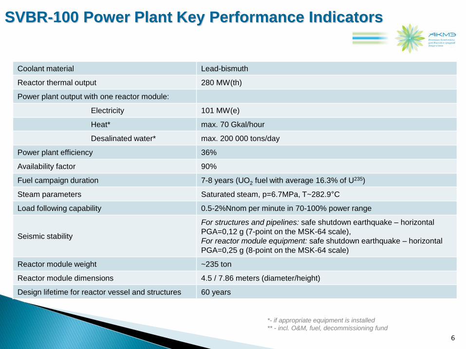
SVBR-100 Power Plant Key Performance Indicators
Coolant material Lead-bismuth
Reactor thermal output 280 MW(th)
Power plant output with one reactor module:
Electricity 101 MW(e)
Heat* max. 70 Gkal/hour
Desalinated water* max. 200 000 tons/day
Power plant efficiency 36%
Availability factor 90%
Fuel campaign duration 7-8 years (UO2 fuel with average 16.3% of U235)
Steam parameters Saturated steam, p=6.7MPa, T~282.9°C
Load following capability 0.5-2%Nnom per minute in 70-100% power range
Seismic stability
For structures and pipelines: safe shutdown earthquake – horizontal
PGA=0,12 g (7-point on the MSK-64 scale),
For reactor module equipment: safe shutdown earthquake – horizontal
PGA=0,25 g (8-point on the MSK-64 scale)
Reactor module weight ~235 ton
Reactor module dimensions 4.5 / 7.86 meters (diameter/height)
Design lifetime for reactor vessel and structures 60 years
*- if appropriate equipment is installed
** - incl. O&M, fuel, decommissioning fund
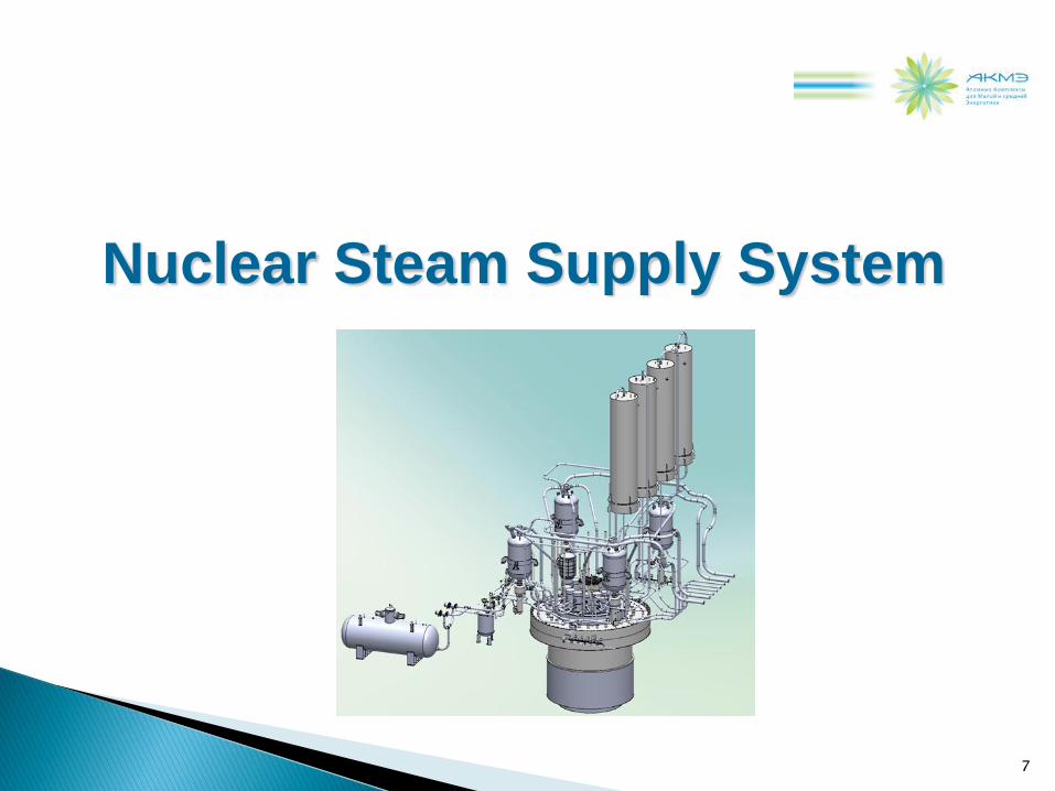
Nuclear Steam Supply System
7

SVBR-100 Reactor Layout
8
Main circulation
pump (MCP) x 2
Steam generator (SG)
modules x 12
Core
Monoblock
vessel
Control
adsorbing
rods
Basic Technical Characteristics of Core Performance
(for UO2 fuel, saturated steam)
Lead-bismuth coolant (LBC) temperature,
input / output, С 350 / 500
Average power density of the core, kW/dm3 160
Average linear load on the fuel element, W/cm 300
Fuel: type
U loading, kg U-235 average enrichment, %
UО2
9100
16.3
Core lifetime, thousand full power hours Not less than 50
Average burn-up, % h.a. 6.9
Max burn-up,% h.a. 11.4
Max Damaging doze, dpa 85

9
Gas System Condenser
Bursting
Membrane
Reactor
Monoblock
(RMB)
Passive
Cooldown Vessel
Feedwater
Saturated
Steam Cooldown
Condenser
Bubbling
Chamber
| 9 |
SVBR-100 NSSS Design
10
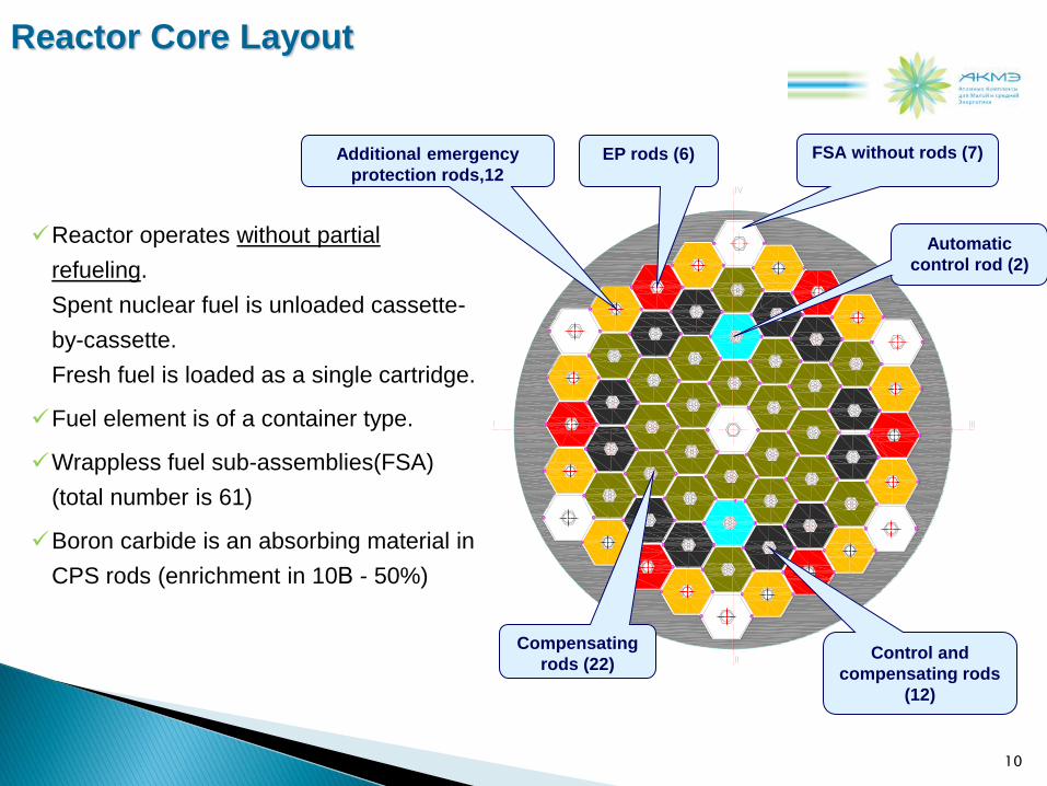
Reactor operates without partial
refueling.
Spent nuclear fuel is unloaded cassette-
by-cassette.
Fresh fuel is loaded as a single cartridge.
Fuel element is of a container type.
Wrappless fuel sub-assemblies(FSA)
(total number is 61)
Boron carbide is an absorbing material in
CPS rods (enrichment in 10В - 50%)
Reactor Core Layout
FSA without rods (7)
Control and
compensating rods
(12)
Compensating
rods (22)
Automatic
control rod (2)
Additional emergency
protection rods,12
EP rods (6)
11
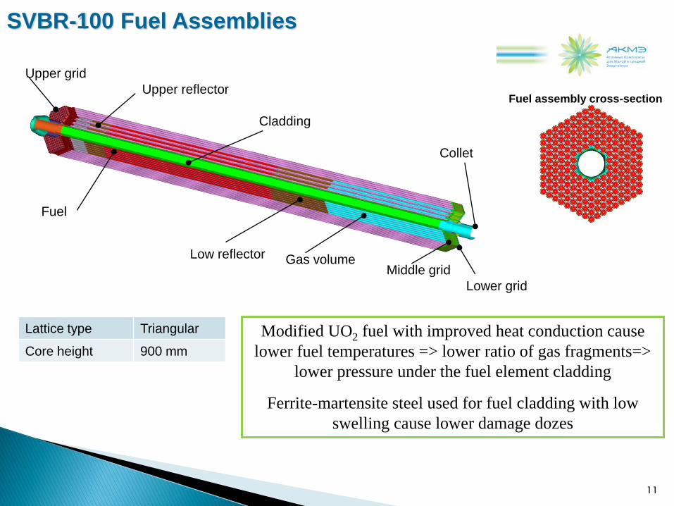
SVBR-100 Fuel Assemblies
Upper reflector
Low reflector
Fuel
Cladding
Gas volume
Upper grid
Lower grid
Collet
Middle grid
Fuel assembly cross-section
Lattice type Triangular
Core height 900 mm
Modified UO2 fuel with improved heat conduction cause
lower fuel temperatures => lower ratio of gas fragments=>
lower pressure under the fuel element cladding
Ferrite-martensite steel used for fuel cladding with low
swelling cause lower damage dozes

12
Displacers
SVBR-100 SG Module
Heat removal rate 23 MWt
Active region height 4465 mm
SG module diameter 570 mm
System pressure 6.7 MPa
Number of tubes 192
Water/Steam temperature 240/282.9 oC
Coolant
entrance
Feedwater
entrance
Steam
SG cross-section
Coolant
flow-out
Coolant
flow-out

13
• An abcence of partial refueling ensures the possibility to change significantly each fuel
load
• At the first stage: UO2 fuel, CBR = 0,84
• MOX fuel, CBR 1:
Due to high content of plutonium, first spent UO2 fuel load can be used as a main
component for a third fresh fuel load and etc. Estimated fuel campaign duration for
uranium nitride or uranium-plutonium fuel is up to 15 years
Fuel Cycle
The consumption of natural
uranium during 60 years could
be by 30 % less than that for
WWER reactors (for 1 GWe)
* G.I.Toshinskiy and Co, “Fuel cycle of reactor SVBR-100”,Global’09

Safety Concept
14

SVBR-100 Safety Principles
Chemically inert
lead-bismuth coolant
Fast reactor
Integral design of the reactor
components:
core, pumps, SG, etc.
Inherent (by-nature)
safety – for free
By-design
safety
First circuit
low pressure
15
Stability & simplicity
under normal operation
Tolerance to the design
and
beyond-design basis
accidents
+
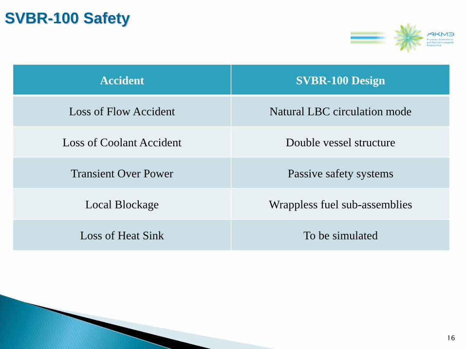
SVBR-100 Safety
16
Accident SVBR-100 Design
Loss of Flow Accident Natural LBC circulation mode
Loss of Coolant Accident Double vessel structure
Transient Over Power Passive safety systems
Local Blockage Wrappless fuel sub-assemblies
Loss of Heat Sink To be simulated

17
SVBR-100: Design Safety Features
Integral layout
of the core, MCP
and SG in
a common vessel
(monoblock)
In case of failure of all cooling systems
and black-out:
no core melting occurs
integrity of the monoblock is provided passively
as a result of heat accumulation by in-vessel
structures and coolant
heat removal is provided with water tank (96 hours)
Absence of the pipelines and primary circuit valves
outside the reactor monoblock:
simplifies the design
prevents from losses of coolant
prevents blockage of circulation of the coolant
through the core

SVBR-100: Fast Reactor
Operating reactivity
margin
is less than
the delay-neutron fraction
no prompt neutrons
runaway (under no condition chain
reaction can go out of control)
No Xe poisoning effects
Small negative
temperature reactivity
coefficient
Special algorithm of controlling
the compensation
absorbing rods
Fast reactor
18

SVBR-100: Lead-Bismuth Coolant
High boiling
Temperature (1670 ºС)
Chemical inertness
of coolant to
water and air
Low primary
circuit pressure
simplification of the reactor design
enhancement of reliability
no possibility of primary circuit’s
over-pressurization and thermal
explosion of the reactor
Accident with
loss-of-sealing in the primary circuit and
with inter-circuit leaks in the SG occur without
hydrogen release and exothermic reactions
No chemical explosions and
internally-caused fires
Coolant – lead-bismuth eutectic alloy
19

20
Impact of Potential Energy of the Coolant
Coolant type Water Sodium Lead,
Lead-bismuth
Parameters P = 16 MPa
Т = 300 ºС
Т = 500 ºС
Т = 500 ºС
Maximal potential energy, GJ/m3, incl.:
~ 21,9 ~ 10 ~ 1,09
Thermal energy
incl. compression
potential energy
~ 0,90
~ 0,15
(PWR)
~ 0,6
None
~ 1,09
None
Potential Chemical energy of interaction
With zirconium
~ 11,4
With water 5,1
With air 9,3 None
Potential chemical energy of interaction of released hydrogen with air
~ 9,6 ~ 4,3 None
Potential hazard from the NPP is determined by two factors:
1. accumulated radiation (radiotoxicity contained in the reactor) facility
2. probability of radioactivity release into the environment
Total radioactivity is proportional to the thermal power of the reactor (size) and duration of its operation, i.e., by
energy production – doesn’t depend on the reactor type
Probability depends on the reactor type and is determined by reactivity margin, feedbacks, design features,
and potential energy, accumulated in the coolant
Coolant potential energy strongly influences the number and complexity of the safety systems and can display
its impact in case of accidents (especially severe)
Source: G.I. Toshinsky et. al “EFFECT OF POTENTIAL ENERGY STORED IN REACTOR FACILITY
COOLANT ON NPP SAFETY AND ECONOMIC PARAMETERS”
21
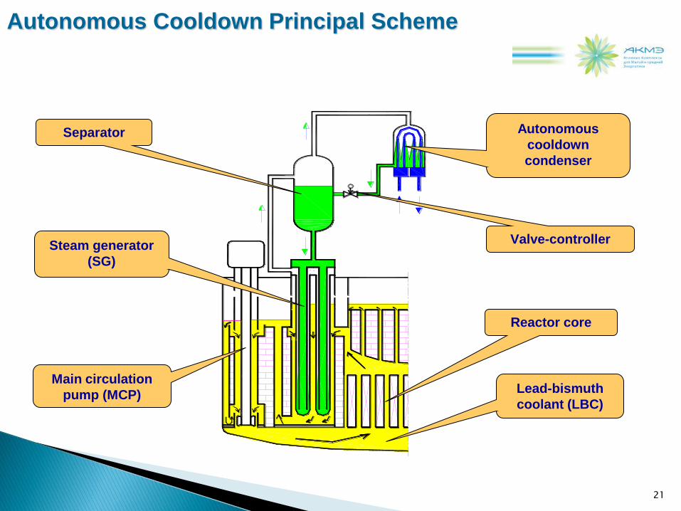
Separator
Steam generator
(SG)
Main circulation
pump (MCP)
Autonomous
cooldown
condenser
Valve-controller
Reactor core
Lead-bismuth
coolant (LBC)
Autonomous Cooldown Principal Scheme

Fusible locks of the additional safety rods to provide passive shutdown of the core
in the event of coolant’s overheating over 700 C caused by CRDM fault
Passive Operation of Safety Systems:
Extraction of the RRs at nominal power without actuation of
the EP rods
22
0 1 0 0
0 . 0
0 . 2
0 . 4
0 . 6
0 . 8
1 . 0
1 . 2
1 . 4
1 . 6
1 . 8
2 . 0
1 0 0
2 0 0
3 0 0
4 0 0
5 0 0
6 0 0 N , r e l T , о С
Time, s
N
Outlet T
Inlet T

р < 1 МПа
Small leak
р = 1 МПа
Large leak
Gas system
condenser
Breaking
membrane
Bursting disk (membrane) prevents the reactor vessel from over-pressurization over 1.0 MPa in case of postulated large leak (several tubes) in the SG
Passive Operation of Safety Systems:
SG internal leak localization
23
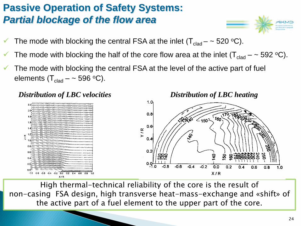
The mode with blocking the central FSA at the inlet (Тclad – ~ 520 оC).
The mode with blocking the half of the core flow area at the inlet (Тclad – ~ 592 оC).
The mode with blocking the central FSA at the level of the active part of fuel
elements (Тclad – ~ 596 оC).
24
Passive Operation of Safety Systems:
Partial blockage of the flow area
High thermal-technical reliability of the core is the result of non-casing FSA design, high transverse heat-mass-exchange and «shift» of
the active part of a fuel element to the upper part of the core.
Distribution of LBC heating Distribution of LBC velocities

Steam generator
(dried)
Lead-bismuth
coolant (LBC)
Reactor core
MCP
(de-energized)
Removal of steam
from
the PHRS tank
PHRS tank filled
with water
Heat sink
(out of)
25
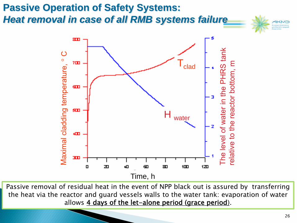
Passive Operation of Safety Systems:
Heat removal in case of all RMB systems failure
26
Time, h
Тclad
H water
Passive removal of residual heat in the event of NPP black out is assured by transferring the heat via the reactor and guard vessels walls to the water tank: evaporation of water
allows 4 days of the let-alone period (grace period).
Passive Operation of Safety Systems:
Heat removal in case of all RMB systems failure

Design/Safety Implications from
the Fukushima Event
27

Reactor
shutdown
SVBR-100 Response to a Fukushima-like Initiating Event
Hard to compare 40-50-ty year old NPP design (though modernized) with “after” Chernobyl &
TMI & Fukushima NPPs designed up to “the lessons learned”
However:
Full blackout
Inability to remove Fuel afterheat
Fuel rods zirconium casing interaction
with water
Growth of temperature in the reactor core
Impossibility to organize
repair works +
Lead-Bismuth Coolant evaporation Not possible. tb = 1670ºC
No zirconium (steel casing)
design features: 96 hours of
non-interference (100 tn water
tank) + no loss of coolant
Hydrogen extraction & explosion Not possible in significant
quantities
No consequences 28

Design Certification and
Deployment Schedule
29

SVBR-100 Project
30
JSC AKME-engineering
- a 50/50 joint venture of Russian State Atomic Corporation Rosatom and EuroSibEnergo (En+ Group),
aimed to commercialize SVBR lead-bismuth nuclear reactor technology.
The company was established in December 2009
The JV’s targets:
• Completion of the R&D for reactor unit/fuel, safety analysis report
• Detailed design of the reactor unit and principal equipment
• Reactor and power plant licensing
• Commissioning of the SVBR pilot plant by the end of 2017
• Development of manufacturing, servicing and marketing infrastructure for commercial serial production and
sales
Growing worldwide interest in SMR
technologies
Strong trend towards inherently safe
and intrinsically secured nuclear power
technologies
Advanced lead-bismuth fast reactor
technology with 80 reactor-years
operational experience on Russian
submarines
Background

31
2011 2014 2018 + 2010 2012 2013 2015 2016 2009 Preliminary design of reactor unit, core and key
equipment, Site selection, Feasibility study
Development of manufacturing and servicing
Infrastructure, Marketing
Construction, Commissioning,
Operation licensing
Pilot operation
Serial
manufacturing of
commercial units 2017 Target:
•Operation license obtained
•Pilot plant commissioned
Status June 2011:
•Site selected
•AKME appointed as operator for pilot
plant
•Siting license works underway
•Specifications on pilot plant approved
•Key R&D on reactor and reactor core are
underway
2013 Targets:
•Preliminary Safety report &
Construction license
obtained
•Reactor & power plant
design completed
Manufacturing and delivery of reactor unit
and power plant components
SVBR-100 Pilot Plant: project schedule and milestones
R&D Preliminary
design Design Construction Operation
Commer-
cialization
Power Plant Design engineering,
Reactor safety report, Construction licensing
2017

32
Licensing Issues for SVBR-100
Key issues to be proved: Solutions in Russian regulatory framework:
? Operation staff requirements Requirements are flexible and depend on safety level of NPP
(proved by a SAR) ? Emergency zone planning
? Distance from residential area
Requirement of the RF Ministry of Emergency is 25 km
distance between NPP and residential area. But there is
practice of reduction this distance up to 1-3 km by additional
justifications
? Safeguard requirements Requirements are fixed and depend on NPP technology and
design (vulnerability analysis)
? Liability insurance
Maximum liability for NPP operator is about $195mln and
causes annual insurance payments which could not be a
financial burden for a SMR operator, but can be additionally
reduced for SMRs
RF regulations are sufficient to carry out activities regarding SVBR during it’s
lifetime and support innovative features of new SMRs
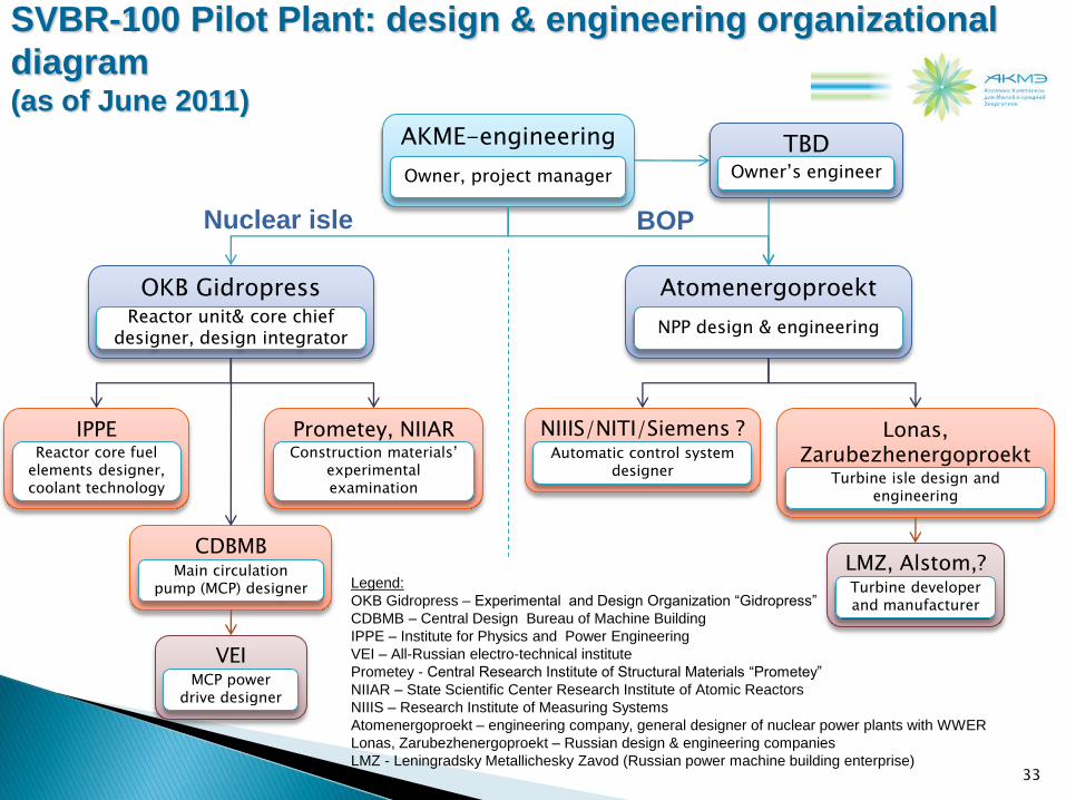
SVBR-100 Pilot Plant: design & engineering organizational
diagram (as of June 2011)
AKME-engineering
Owner, project manager
OKB Gidropress Reactor unit& core chief
designer, design integrator
Atomenergoproekt
NPP design & engineering
TBD Owner’s engineer
CDBMB Main circulation
pump (MCP) designer
IPPE Reactor core fuel
elements designer, coolant technology
Prometey, NIIAR Construction materials’
experimental examination
NIIIS/NITI/Siemens ? Automatic control system
designer
Lonas, Zarubezhenergoproekt
Turbine isle design and engineering
LMZ, Alstom,? Turbine developer and manufacturer
VEI MCP power
drive designer
33
Nuclear isle BOP
Legend:
OKB Gidropress – Experimental and Design Organization “Gidropress”
CDBMB – Central Design Bureau of Machine Building
IPPE – Institute for Physics and Power Engineering
VEI – All-Russian electro-technical institute
Prometey - Central Research Institute of Structural Materials “Prometey”
NIIAR – State Scientific Center Research Institute of Atomic Reactors
NIIIS – Research Institute of Measuring Systems
Atomenergoproekt – engineering company, general designer of nuclear power plants with WWER
Lonas, Zarubezhenergoproekt – Russian design & engineering companies
LMZ - Leningradsky Metallichesky Zavod (Russian power machine building enterprise)

34
Thank you!
JSC “AKME-engineering”
Tel. +7 495 7307960
Fax +7 495 7306292
24 B.Ordynka str., Moscow 119017, Russia
www.akmeengineering.com