Embed Size (px)
Citation preview
WITHOUT BRACKET
1. Casing12. Rotor and Shaft13. Idler bush14. Idler15. Idler pin16. Head17. M
ain bushing18. Stuffing box19. G
land110. By-pass body
11. Clack
12. Spring
13. By-pass cover
14. Adjusting bolt
15. Cap
TYPE
M
DIM
EN
SIO
NS
WITH
OU
T BR
AC
KE
TS
ECACCBB53 AB
3/8"
1"
2"2"
21/2"
21/2"
3"6" AB
B1
CD
EF
GH
JK
LM
NO
RS
W
-74
125
160
160
200
245
42-158
190
190
232
270
68
124
204
260
260
380
440
3374
118
155
155
220
250
-41708080
105
125
-32507474
108
157
--1314141823
-233032322460
-1011151521
17,5
12182835354555
--110
130
130
160
240
--140
160
160
200
285
46810101216
-81218182020
-32,5
4545456070
140
230
440
500
525
610
770
-58
104
110
110
175-
kg27334048
135
180
3" B (B
y-Pass and
Jacketed Body)
HEAVY DUTY INTERNAL ECCENTRIC GEAR PUMPS
3/8" MK
(With B
racket)
1" E (Tapped P
ort)
1" E (Jacketed H
ead)
1" EK
(Flanged)
2" CA
K (Flanged)
2½" C
K (W
ith bracket,blind head)
2-2½ C
K-C
BK
(U P
ort)
3"B3" B
K (W
ith Bracket)
6" (53)A
B (Jacketed H
ead)
INTE
RN
AL E
CC
EN
TRIC
GE
AR
PU
MP
S: D
ue to the large gear pitch giving greater tolerance betw
een gears the pum
p can be used for more viscous
pro
du
cts, fo
r e
xam
ple
, m
ola
sse,
chocolate, bitumen, grease and even for
crushing of soft solids. Pressures up to 15
bar are obtained.
Operating P
rinciple: Internally the pump has tw
o gears and a crescent. The rotor (large gear) is driven by the m
otor and drives the idler gear. As
the gears unmesh liquid is draw
n into the pump (1). The crescent
separates the liquid and acts as a seal between the rotor and the idler (2).
In (3) the pump casing is full of liquid. A
s the gears mesh (4) the liquid is
forced out of the discharge port. This action gives continuous non-pulsating flow
.CA
PA
CITY
CH
AR
TP
UM
P TY
PE
WIT
HO
UT
BR
AC
KE
TW
ITH
BR
AC
KE
T
MAXPRESSURE
BAR
PORTSIZE
It./RLT/Min
m3/hRPM
KWHP
POWER kWWeight KG
MIN.MAX.
WithoutBracket
WithBracket
MECACCBB
53 AB
MK
EK
CA
KC
KC
BK
BK
DC
CD
K
3/8"
1"2"
2½"
2½"
3"
1½"
2"6"
101012141414 121214
0,004
0,022
0,44
0,85
1,45
2,1
0,052
0,13
5,85
5,83
33
200
375
580
840
78
130
1755
0,35
212
22,5
3550
4,7
7,8
100
1500
1500
450
450
400
400
1500
1000
300
0,55
1,1
5,5
7,5
1111
1,1330
0,75
1,5
7,5
101515
1,5440
0,25
0,55
345,5
11
0,75
1,5
22
0,75
1,1
7,5
111537 37,5
45
27334048
135 --
210
313549397
240
1842-
WITH BRACKET
1. Casing
12. Bracket13. R
otor and Shaft14. Idler15. Idler pin16. H
ead17. G
land18. M
ain Bushing19. N
ut110. Sleeve11. R
ing12. Adjust D
rum13. Lip Seal14. R
oller Bearing15. N
ut16. Locking Sheet17. N
ut
TYPE
MK
DIM
EN
SIO
NS
WITH
BR
AC
KE
TS
EKDC
CDK
CAK
CK
CBK
BK
3/8"
1"
11/2"
2"2"
21/2"
21/2"
3" AB
B1
CD
EF
JK
LM
NO
ST
VW
kg
-7478-130
165
165
196
4290
103
125
158
190
190
232
68
124
124
160
205
260
260
380
467689
130
140
180
180
262
303870
100
100
9090
178
2875587070
100
100
208
8,512121313131322
1218202728303045
-7590
125
110
130
130
160
-105
120
165
140
160
160
200
-12141813141418
1014131515191932
140
335
370
470
510
560
600
835
-35406060606080
466888814
-585865
105
110
110
170
3131843549397
220
HELICAL OR SPUR GEAR PUMPS
1-1½" X
LAK
4-2½" X
LAK
(By-P
ass)
2½" X
LA (Jacketed B
ody /Jacketed C
over)
4" XL (For D
istributer)
10" XL
PU
MP
TYP
EMAX
PRESSUREBAR
PORTSIZE
It./RIt./dk
m3/hRPM
KWHP
POWER kWWeight KG
MIN.MAX.
1" XLA
K1½
" XLA
K
4" XLD
BT
4" XL
8XLC
10" XL
2" XLC
B2½
" XLADBT
1"
1½"
2½"
4"4"8" 2"
2½"
10"
202015151515 151515
0,055
0,11
1,04
2,22
2,22
7,5
0,44
1,04
11,7
82,5
165
460
1000
1000
2250
440
460
2925
510276060
135
26,4
27
175
1500
1500
450
450
450
300
1000
450
250
2,2
5,5
5,5
111530
5,5
5,5
75
37,5
7,5
152040
7,5
7,5
102
2,2
1,1
5,5
111115
5,5
5,5
35
37,5
15223737 1515
130
152170
110
105- 70
100
760
CA
PA
CITY
CH
AR
T
2½" XLA1
23
Operating P
rinciple: The external pump also has a drive gear
(driven by the powers source)and a driven gear. The gears run in
opposite directions (1) and the liquid carried around the outside betw
een the gears and the casing (2). As the gears re-m
esh on the discharge side the liquid is forced out into the discharge line. The action gives a continuous non-pulsating flow
.
PU
MP
S: C
ompared to the internal gear pum
ps, the gear pitch is finer. B
eing helical gear, the pump
have a quieter operation. Pum
ps are generally used for less viscous liquids and run at higher speeds. P
ressure up to 30 bar are obtained.
US
AG
E A
RE
AS
OF
VIM
PI'S
PU
MP
S
l Em
ulsionl B
itumen
l Asphalt
l Pigm
entsl Fuel-oill M
ineral oill H
ot oill P
etroleuml LP
Gl P
araffinl D
etergentsl C
hocolatel G
lucosel Foodl G
lycerinel M
olassel A
lcoholl R
esin (Glue)
l Soap
l Sham
poosl O
live Oil
l Acids
l Alkalies
l Solvents
11. Main Body
2. Gears
13. Back Cover14. Front Cover15. Driven Shaft1
16. Driving Shaft7. Bushing
18. Bushing19. Packing G
land110. Shaft Nut
VA
LVE
SJacketed V
alves .Three W
ays Valves .
Spray B
ar Valves .
TYPE
XLAK
DIM
EN
SIO
NS
XLAK
XLA
XL
XLB
XLADB
XLADBT
1"
1½"
2½"
4"
10"
2½"
2½"
AB
CD
EF
GK
1K
LM
NO
PR
ST
7095
158
158
338
158
158
100
100
163
362
163
163
163
174
178
305
305
456
305
305
7873
109
109
245
109
109
7585
130
180
335
130
130
100
115
165
220
380
165
165
1828
M24
M24
85
M24
M24
20304088404040
-----600
600
195
250
440
545
1040--
------65
10101418251414
138
180
254
260
380
254
254
5567
142
230
300
142
142
M10
M12
M12
M16
M16
M12
M12
68882088
kg152170
105
760
105
100
PU
MP
TYP
EInternal
Eccentric
Helical
HighPressure
Vane
Exte
rnal
Parts
(Body, C
asin
g,
Bra
cket)
Cast Iron
Inte
rnal
Parts
(Idle
r, Gear,
Vanes)
Shaft, Idler
Pin
Gear
Bushing
Main
Bushing
Shaft
Sealing
Cast Iron
Cast Iron
Cast Iron
Cast Iron
Cast Iron
Steel
Steel
SteelBronze
BronzePacking
Steel-
BronzePacking
Steel-
BronzeLipseal
Steel-
BallBearing
Packing
XLDB
XLDBT
4"4"
158
158
163
163
305
305
109
109
180
180
220
220
M24
M24
4040
675
675
--
-65
1818
260
260
260
260
M16
M16
88
125
140RL
1/4"-
4248
4127
--
348
12,7-
--
855
164-
2,5
AK6"
229-
-297
105102
1945
240-
23-
760100
12x8-
245
AK
6"14
3,83229,8
92400
118
455
-245
1/4RL
1/4"10
0,00111,66
0,11500
0,550,75
0,250,75
2,5-
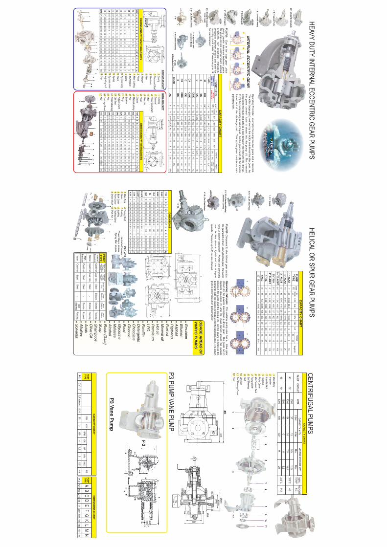
CENTRIFUGAL PUMPS
INLET
CAPACITY CHART
OUTLET
RPM3
CAPACITY m/h
MO
TOR PO
WER KW
MAX.
TEMP
WEIGHTKG
0 Bar4 Bar
Min
Max
o320
Co320
C
40
143
4065
3240
1500300015003000
375490160
15300120
5,57,51,511
11,518,53,220
1. Main Body
12. Impeller
13. Impeller N
ut14. Packing15. Front C
over16. M
echanical Seal17. Pum
p Shaft18. Ball Bearing19. Port110. Lip Seal11. Ball Bearing C
over12. Foot
P3 PUMP VANE PUM
P
P3 Vane P
ump
PUMPTYPE
lt/dk
m3/h
RPM
KW
HP
MIN.
MAX.
P-1P-3
1"1"
2½" - 2"
0,5 Vakum0,5 Vakum
0,138
0,275
0,3124050
3160
45,5
25,5
46
PUMPTYPE
P-1P-3
AB
CD
EF
GK
LM
N
R1"R2½"
83R2"
158216
9514
260170
45465
4810
KG
DIMENSIO
NS CHARTCAPACITY CHART
D
D11/2"
78-
12480
5440
-30
1125
--
810
40330
5812

P.O. BOX 2748
PARKLANDS 2121
TEL: 011 442-9184
FAX: 011 788-7138
US
EF
UL
INF
OR
MA
TIO
N
VIS
CO
CIT
Y
CA
PA
CIT
Y
CE
NTIS
TOK
ES
=C
EN
TIPO
ISE
SP
EC
IFIC G
RA
VITY
SS
U = C
EN
TISTO
KE
S x 4,55
L/S
1
0,0630,076
UK
US
GP
MG
PM
13,215,85
0,8331
11,2
PO
WE
RP
RE
SS
UR
E
KW1
0,746
HP
1,340
1
1 BA
R
1 M
1 M
===
10,190 M
9,805 kPa
1,422 PS
i
INF
OR
MA
TIO
N R
EQ
UIR
ED
FO
R S
EL
EC
TIN
G A
PU
MP
DU
TY
TE
MP
ER
AT
UR
E
LIQU
ID
FLOW
RA
TE
TOTA
L HE
AD
SU
CTIO
N C
ON
DITIO
N
TEM
PE
RA
TUR
E
S.G
.
PH
VA
LUE
VIS
CO
CITY
1"1 FOO
T
1 MILE
===
25,4mm
30,48cm
1,609km
1mm
1cm
1meter
===
0,039 IN
0,0328 FT
1,094 YD
S
LIQU
ID
°F = °C x 1,8 + 32
TOTA
L HE
AD
°C = (F - 32)
1,8
LEN
GTH
VIMPI
GE
AR
PU
MP
S
Used in
vario
us In
dustria
l applic
atio
ns, th
e b
urn
er u
ses a
fuel / a
ir mix
ture
whic
h s
aves fu
el u
sage.
Most fu
el ty
pes
can b
e u
sed a
nd th
e a
ir / fuel m
ixtu
re is
set w
ith a
sin
gle
lever
for e
asy o
pera
tion.
BURNER
COLLOIDAL EMULSION M
ILL
Collo
idal E
muls
ion M
ill is a
n a
ppara
tus w
hic
h e
nsure
s h
om
ogeniz
ed p
hysic
al m
ixtu
re o
f the tw
o
diffe
rent liq
uid
s in
sid
e e
ach o
ther.
If rota
ting s
peed a
nd d
efin
ite p
ressure
, whic
h a
re a
ppro
pria
te
accord
ing to
the m
ixtu
re ra
te, a
re g
iven fro
m tw
o d
iffere
nt fe
edin
g p
um
ps, th
e p
roduct b
etw
een 1
0 -
3
15m
can b
e o
bta
ined d
ue to
the v
iscosity
the liq
uid
.
DISCHARGEPORT
SUCTIONPORT
TYPEPOW
ERNOISERATIO
STATICPRESSURE
WORKING
PRESSUREMAX. TEMP.
OCW
EIGHTC. SPEED
VE
M 0
1V
EM
02
17 m/s
*VEM
-0122 Kw
40dB16 Bar
6 Baro
250C
175 Kg10-15
17 m/s
*VEM
-0215 Kw
30dB16 Bar
6 Baro
250C
220 Kg10-15
HIGH PRESSURE PUMPS
These p
um
ps o
pera
te o
n th
e s
am
e p
rincip
le a
s s
tandard
exte
rnal g
ear p
um
ps. O
ne g
ear, d
riven th
rough th
e
input s
haft d
rives a
second g
ear.
As th
e g
ears
un-m
esh (1
) the liq
uid
is d
raw
n in
to th
e p
um
p. T
his
is th
en
carrie
d ro
und th
e c
asin
g o
f the p
um
p (2
) and d
ischarg
ed a
s th
e g
ears
re-m
esh (3
).
Dependin
g o
n v
iscositie
s p
ressure
up to
30 b
ar c
an b
e o
bta
ined.
YB
0,5
PU
MP
YB
1 A
ND
YB
2 P
UM
P
CA
PA
CIT
Y C
HA
RT