Embed Size (px)
Citation preview

HDO4000 High Definition Oscilloscopes200 MHz – 1 GHz
Key Features
• 12-bit ADC resolution, up to 15-bit with enhanced resolution
• 200 MHz, 350 MHz, 500 MHz, 1 GHz bandwidths
• Long Memory – up to 50 Mpts
• 12.1” touch screen display
• Multi-language User Interface
• WaveScan – Search and Find
• LabNotebook Documentation and Report Generation
• History Mode
• Spectrum Analyzer Mode
• Power Analysis Software
• Serial Data Trigger and Decode
• 16 Digital Channels with 1.25 GS/s – Analog and Digital Cross-Pattern Triggering – Digital Pattern Search and Find – Analog and Digital Timing Measurements – Activity Indicators
HD4096 TechnologyHD4096 high definition technology consists of high sample rate 12-bit ADCs, high signal-to-noise input amplifiers and a low-noise system architecture. This technology enables high definition oscilloscopes to capture and display signals of up to 1 GHz with high sample rate and 16 times more resolution than other oscilloscopes.
Long MemoryWith up to 50 Mpts of memory the HDO4000 High Definition Oscilloscopes can capture large amounts of data with more precision than other oscilloscopes. The 2.5 GS/s, 50 Mpts architecture provides the ability to capture a fast transient or a long acquisition.
Large 12.1” Touch ScreenNavigating complicated user interfaces is a thing of the past thanks to the large touch screen display of the HDO4000. The user interface was designed for touch screens which makes navigating the HDO4000 extremely intuitive. Every aspect of the interface is touchable making channel, timebase and trigger settings only one touch away.
Compact Form FactorThe HDO4000 builds upon Teledyne LeCroy’s history of “Large Screen, Small Footprint” with its 12.1” wide touch screen display and 5” depth. Additionally, the innovative rotating, tilting feet enable the HDO4000 to be placed in 4 different viewing positions ensuring optimal viewing no matter where it is being positioned in the lab.
Combining Teledyne LeCroy’s HD4096 high definition technology, with long memory, a compact form factor, 12.1” wide touch screen display, powerful debug tools, and mixed signal capability, the HDO4000 is the ideal oscilloscope for precise measurements and quick debug. Tools such as WaveScan Search and Find, LabNotebook Report Generator, and History Mode help identify and isolate problems for faster troubleshooting.
2
HD4096 HIGH DEFINITION TECHNOLOGY
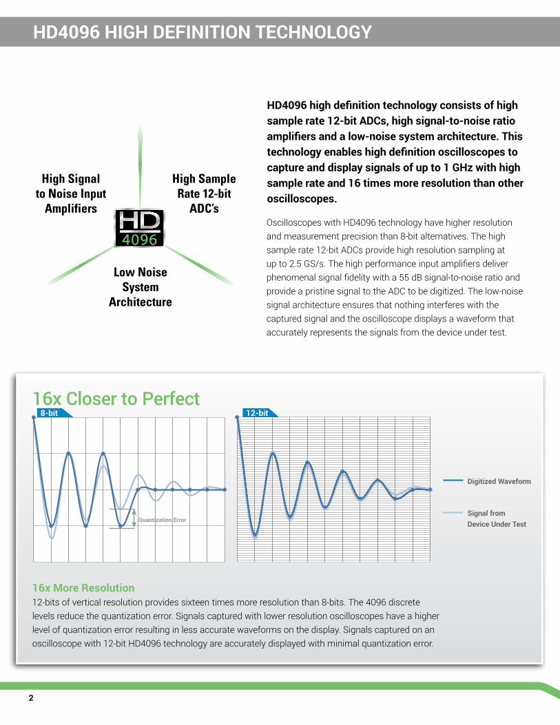
HD4096 high definition technology consists of high sample rate 12-bit ADCs, high signal-to-noise ratio amplifiers and a low-noise system architecture. This technology enables high definition oscilloscopes to capture and display signals of up to 1 GHz with high sample rate and 16 times more resolution than other oscilloscopes.
Oscilloscopes with HD4096 technology have higher resolution and measurement precision than 8-bit alternatives. The high sample rate 12-bit ADCs provide high resolution sampling at up to 2.5 GS/s. The high performance input amplifiers deliver phenomenal signal fidelity with a 55 dB signal-to-noise ratio and provide a pristine signal to the ADC to be digitized. The low-noise signal architecture ensures that nothing interferes with the captured signal and the oscilloscope displays a waveform that accurately represents the signals from the device under test.
High Sample Rate 12-bit
ADC’s
High Signal to Noise Input
Amplifiers
Low Noise System
Architecture
16x More Resolution12-bits of vertical resolution provides sixteen times more resolution than 8-bits. The 4096 discrete levels reduce the quantization error. Signals captured with lower resolution oscilloscopes have a higher level of quantization error resulting in less accurate waveforms on the display. Signals captured on an oscilloscope with 12-bit HD4096 technology are accurately displayed with minimal quantization error.
Digitized Waveform
Signal from Device Under Test
16x Closer to Perfect 8-bit 12-bit
Quantization Error

3
DEBUG IN HIGH DEFINITION WITH HD4096
Clean, Crisp Waveforms
When compared to waveforms captured and displayed by 8-bit oscilloscopes, waveforms captured with HD4096 technology are dramatically crisper and cleaner. Oscilloscopes with HD4096 acquire waveforms at high resolution, high sample rate and low noise to display the most accurate waveforms.
More Signal Details
Signal details often lost in the noise are clearly visible and easy to distin-guish when captured on oscilloscopes with HD4096. Details which were previously difficult to even see can now be easily seen and measured. Using the oscilloscope zoom capabilities gives an even closer look at the details for unparalleled insight to the signals on screen.
Unmatched Measurement Precision
Precise measurements are critical for effective debug and analysis. HD4096 enables oscilloscopes to deliver unmatched measurement precision to improve testing capabilities and provide better results.
Oscilloscopes with HD4096 have a variety of benefits that allow the user to debug in high definition. Waveforms displayed by high definition oscilloscopes are cleaner and crisper. More signal details can be seen and measured; these measurements are made with unmatched precision resulting in better test results and shorter debug time.
8-bit 12-bit
A
A A
B BC C
B
C
Clean, Crisp Waveforms | Thin traces show the actual waveform with minimal noise interference
Unmatched Measurement Precision | Measurements are more precise and not affected by quantization noise
More Signal Details | Waveform details lost on an 8-bit oscilloscope can now be clearly seen

4
HDO4000 High Definition Oscilloscopes combine Teledyne LeCroy’s HD4096 high definition technology with long memory, powerful debug tools and mixed signal capability in a compact form factor with a 12.1” touch screen display.
1. Only 13 cm (5”) Deep – The most space-efficient oscilloscope for your bench from 200 MHz to 1 GHz
2. 12.1” Widescreen (16 x 9) high resolution WXGA color touch screen display. The most time-efficient user interface is even easier to use with a built-in stylus
3. Local language user interface – Select from 10 language preferences. Add a front panel overlay with your local language
4. “Push” Knobs – All knobs have push functionality that provides shortcuts to common actions such as Set to Variable, Find Trigger Level, Zero Offset, and Zero Delay
5. Waveform Control Knobs – Control channel, zoom, math and memory traces with the multiplexed vertical and horizontal knobs
HDO4000 - HIGH DEFINITION OSCILLOSCOPE
2
1
8
10

5
6. Dedicated Cursor Knob – Select type of cursor, position them on your signal, and read values without ever opening a menu
7. Dedicated buttons to quickly access popular debug tools.
8. Easy connectivity with two convenient USB ports on the front, two on the side
9. Mixed Signal Capability - Debug complex embedded designs with integrated 16 channel mixed signal capability
10. Rotating and Tilting Feet provide 4 different viewing positions
11. Auxiliary Output and Reference Clock Input/Output connectors for connecting to other equipment
12. USBTMC (Test and Measurement Class) port simplifies programming
Document and Share:
• Quickly save all files with LabNotebook
• Create custom reports with LabNotebook
• Save to internal hard disk or network drive
• Print to a USB printer
• Save to USB memory stick
• Connect with LAN or GPIB
• View data on a PC with free WaveStudio utility
5
4
6
7
3
8
10
911 12

6
High-performance 16 Channel Mixed Signal CapabilityWith embedded systems growing more complex, powerful mixed signal debug capabilities are an essential part of modern oscilloscopes. The 16 inte-grated digital channels and set of tools designed to view, measure and analyze analog and digital signals enable fast debugging of mixed signal designs.
Extensive TriggeringFlexible analog and digital cross-pattern triggering across all 20 channels provides the ability to quickly identify and isolate problems in an embedded system. Event triggering can be con-figured to arm on an analog signal and trigger on a digital pattern.
Advanced Digital Debug ToolsUsing the powerful parallel pattern search capability of WaveScan, patterns across many digital lines can be iso-lated and analyzed. Identified patterns are presented in a table with timestamp information and enables quick search-ing for each pattern occurrence. Use a variety of many timing parameters to measure and analyze the characteristics of digital busses. Powerful tools like trends, statistics and histicons provide additional insight and help find anomalies. Quickly see the state of all the digital lines at the same time using convenient activity indicators.
POWERFUL MIXED SIGNAL CAPABILITIES
Teledyne LeCroy’s HDO4000-MS High Definition mixed signal oscilloscope combines the high definition analog channels of the HDO4000 with the flexibility of 16 digital inputs. In addition, the many triggering and decoding options turn the HDO4000-MS into an all-in-one analog, digital, serial debug machine.

7
SERIAL TRIGGER AND DECODE OPTIONS
Trigger and DecodeThe serial data trigger will quickly iso-late events on a bus eliminating the need to set manual triggers and hoping to catch the right information. Trigger conditions can be entered in binary or hexadecimal formats and conditional trigger capabilities even allow trigger-ing on a range of different events. Protocol decoding is shown directly on the waveform with an intuitive, color-coded overlay and presented in binary, hex or ASCII. Decoding on the HDO4000 is fast even with long mem-ory and zooming in to the waveform shows precise byte by byte decoding.
Table and SearchTo further simplify the debug process all decoded data can be displayed in a table below the waveform grid. Select-ing an entry in the table with the touch screen will display just that event. Additionally, built-in search functional-ity will find specific decoded values. Serial data messages can be quickly located by searching on address, data and other attributes specific to a particular protocol. Once found, the specific location containing the specified search criteria can be auto-matically zoomed to.
Supported Serial Data Protocols
• I2C, SPI, UART
• CAN, CAN FD, LIN, FlexRay™, SENT
• Ethernet 10/100BaseT, USB 1.0/1.1/2.0, USB 2.0-HSIC
• Audio (I2S, LJ, RJ, TDM)
• MIL-STD-1553, ARINC 429, SpaceWire
• MIPI D-PHY, DigRF 3G, DigRF v4
• Manchester, NRZ
View decoded protocol information on top of physical layer waveforms and trigger on protocol specific messages.

8
IDENTIFY AND ISOLATE PROBLEMS FASTER
WaveScan Advanced SearchWaveScan provides powerful isolation capabilities that hardware triggers can’t provide. WaveScan allows searching analog, digital or parallel bus signal in a single acquisition using more than 20 different criteria. Or, set up a scan condi-tion and scan for an event over hours or even days.
Advanced Math and MeasureWith many math functions and measurement parameters available, the HDO4000 can measure and analyze every aspect of analog and digital waveforms. By utilizing HD4096 tech-nology, the HDO4000 measures 16 times more precisely than traditional 8-bit architectures. Additionally, the HDO4000 provides statistics, histicons and trends to show how waveforms change over time.
Advanced Waveform Capture with Sequence ModeUse Sequence mode to store up to 10,000 triggered events as segments. This is ideal when capturing fast pulses in quick succession or when capturing events separated by long time periods. Each segment has a timestamp and dead-time between triggers is less than 1 μ s. Isolate rate events over time by combining with advanced triggers.
Touch Screen Simplicity Configuring the HDO4000 is simple thanks to the intuitive touch screen user interface. Everything on the screen is interactive. To adjust channel, timebase, or trigger settings, simply touch the associated descriptor box and the appropriate menu is opened. Measurements can be touched to adjust their settings and cursors can be positioned precisely by touching and dragging them to the proper location. A box can be drawn around a portion of a waveform to create a zoom. Even waveform offset and delay can be adjusted by touching and dragging the waveform.

9
IDENTIFY AND ISOLATE PROBLEMS FASTER
History Mode Waveform PlaybackScroll back in time using History Mode to view previous waveforms and isolate anomalies. Use cursors and measurement parameters to quickly find the source of problems. History mode is always available with a single button press, no need to enable this mode and never miss a waveform.
LabNotebookThe LabNotebook feature of HDO4000 provides a report generation tool to save and document all your work. Saving all displayed waveforms, relevant settings, and screen images is all done through LabNotebook, eliminating the need to navigate multiple menus to save all these files independently.
V/divT/div
Memory LengthSample RateMeasurement
Math
WAVEFORM
OSCILLOSCOPE SET UP
SCREEN DUMP
PRINTER
HARD DRIVE
USB DRIVE
Document Your Work One-touch Functionality Save Your Work Recall Jobs
Easy report generation helps you share your findings and
communicate important results.
LabNotebook adds a simple way to report your work and save all essential
waveforms, settings, and screen images.
Quickly save all the necessary files with LabNotebook in a
single button press.
Recall your settings from any report
by using the Flashback capability.
FLAS
HBA
CKFL
ASH
BACK
FLAS
HBA
CK
LABNOTEBOOK
Go Back in Time to Identify the Source of a Problem
10
SPECTRUM ANALYZER OPTION
Simplify Analysis of FFT Power Spectrum
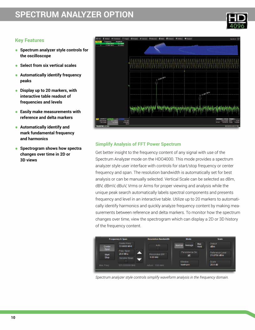
Get better insight to the frequency content of any signal with use of the Spectrum Analyzer mode on the HDO4000. This mode provides a spectrum analyzer style user interface with controls for start/stop frequency or center frequency and span. The resolution bandwidth is automatically set for best analysis or can be manually selected. Vertical Scale can be selected as dBm, dBV, dBmV, dBuV, Vrms or Arms for proper viewing and analysis while the unique peak search automatically labels spectral components and presents frequency and level in an interactive table. Utilize up to 20 markers to automati-cally identify harmonics and quickly analyze frequency content by making mea-surements between reference and delta markers. To monitor how the spectrum changes over time, view the spectrogram which can display a 2D or 3D history of the frequency content.
Spectrum analyzer style controls simplify waveform analysis in the frequency domain.
Key Features
• Spectrum analyzer style controls for the oscilloscope
• Select from six vertical scales
• Automatically identify frequency peaks
• Display up to 20 markers, with interactive table readout of frequencies and levels
• Easily make measurements with reference and delta markers
• Automatically identify and mark fundamental frequency and harmonics
• Spectrogram shows how spectra changes over time in 2D or 3D views
11
POWER ANALYZER OPTION
Power Analyzer Automates Switching Device Loss Measurements
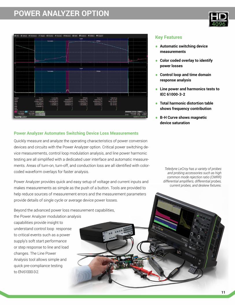
Quickly measure and analyze the operating characteristics of power conversion devices and circuits with the Power Analyzer option. Critical power switching de-vice measurements, control loop modulation analysis, and line power harmonic testing are all simplified with a dedicated user interface and automatic measure-ments. Areas of turn-on, turn-off, and conduction loss are all identified with color-coded waveform overlays for faster analysis. Power Analyzer provides quick and easy setup of voltage and current inputs and makes measurements as simple as the push of a button. Tools are provided to help reduce sources of measurement errors and the measurement parameters provide details of single cycle or average device power losses. Beyond the advanced power loss measurement capabilities, the Power Analyzer modulation analysis capabilities provide insight to understand control loop response to critical events such as a power supply’s soft start performance or step response to line and load changes. The Line Power Analysis tool allows simple and quick pre-compliance testing to EN 61000-3-2.
Teledyne LeCroy has a variety of probes and probing accessories such as high common mode rejection ratio (CMRR)
differential amplifiers, differential probes, current probes, and deskew fixtures.
Key Features
• Automatic switching device measurements
• Color coded overlay to identify power losses
• Control loop and time domain response analysis
• Line power and harmonics tests to IEC 61000-3-2
• Total harmonic distortion table shows frequency contribution
• B-H Curve shows magnetic device saturation

12
PROBES
ZS Series High Impedance Active Probes ZS2500, ZS1500, ZS1000, ZS2500-QUADPAK, ZS1500-QUADPAK, ZS1000-QUADPAK
The ZS Series probes provide high impedance and an extensive set of probe tips and ground accessories to handle a wide range of probing scenarios. The high 1 MΩ input resistance and low 0.9 pF input capacitance mean this probe is ideal for all frequencies. The ZS Series probes provide full system bandwidth for all Teledyne LeCroy oscilloscopes having bandwidths of 1 GHz and lower.
Differential Probes (200 MHz – 1.5 GHz)ZD1500, ZD1000, ZD500, ZD200
High bandwidth, excellent common-mode rejection ratio (CMRR) and low noise make these active differential probes ideal for applications such as automotive development (e.g. FlexRay) and failure analysis, as well as wireless and data communication design. The ProBus interface allows sensitivity, offset and common-mode range to be displayed on the oscilloscope screen.
High Voltage Differential ProbesHVD3102, HVD3106, HVD3106-6M, HVD3206, HVD3605, AP031
Low cost active differential probes are intended for measuring higher voltages. The differential techniques employed permit measurements to be taken at two points in a circuit without reference to the ground, allowing the oscilloscope to be safely grounded without the use of opto-isolators or isolating transformers.
High Voltage Passive ProbesHVP120, PPE1.2KV, PPE2KV, PPE4KV, PPE5KV, PPE6KV
High voltage probes are suitable for a wide range of applications where high-voltage measurements must be made safely and accurately. There are several fixed attenuation probes covering a range from 1 kV to 6 kV and varying transient overvoltage ratings. All of these high voltage probes feature a spring loaded probe tip and a variety of standard accessories to make probing high voltages safe and easy. Additionally, all of the high voltage probe have a probe sense pin to automatically configure the oscilloscope for use with the probe.
Current ProbesCP031, CP031A, CP030, CP030A, AP015, CP150, CP500, DCS015, CA10
Available current probes reach bandwidths of 100 MHz, peak currents of 700 A and sensitivities of 10 mA/div. Use multiple current probes to make measurements on three-phase systems or a single current probe with a voltage probe to make instantaneous power measurements. Teledyne LeCroy current probes enable the design and testing of switching power supplies, motor drives, electric vehicles, and uninterruptible power supplies.
Probe AdaptersTPA10, TPA10-QUADPAK
Probe adapters provide simple and easy interface of third-party probes as well as change between the different Teledyne LeCroy Oscilloscope input and cable types (ProBus, ProLink, K/2.92 mm, BNC and SMA). Depending on the adapters, changing between the Teledyne LeCroy Oscilloscope’s input type may have an effect on the overall performance of the channel.
The right probe is an essential tool for accurate signal capture and Teledyne LeCroy offers an extensive range of probes to meet virtually every probing need.

13
SPECIFICATIONS
HDO4022 HDO4022-MS
HDO4024 HDO4024-MS
HDO4032 HDO4032-MS
HDO4034 HDO4034-MS
HDO4054 HDO4054-MS
HDO4104 HDO4104-MS
Analog - VerticalBandwidth (@ 50Ω) 200 MHz 350 MHz 500 MHz 1 GHzRise time 1.75 ns typical 1 ns typical 700 ps typical 450 ps typicalInput Channels 2 4 2 4 4 4Vertical Resolution 12-bits; up to 15-bits with enhanced resolution (ERES)Sensitivity 50 Ω: 1mV/div - 1 V/div; 1 MΩ: 1 mV/div - 10 V/divDC Gain Accuracy ±(0.5%) Full Scale, offset at 0 VBW Limit 20 MHz, 200 MHzMaximum Input Voltage 50 Ω: 5 Vrms; 1 MΩ: 400 V max (DC + Peak AC ≤ 10 kHz) Input Coupling 50 Ω: DC, GND; 1 MΩ: AC, DC, GNDInput Impedance 50 Ω ±2.0%, 1 MΩ ±2.0% || 15 pFOffset Range 50 Ω: 1 mV - 4.95 mV: ±1.6 V, 5 mV - 9.9 mV: ±4 V, 10 mV - 19.8 mV: ±8 V, 20 mV - 1 V: ±10 V
1 MΩ: 1 mV - 4.95 mV: ±1.6 V, 5 mV - 9.9 mV: ±4 V, 10 mV - 19.8 mV: ±8 V, 20 mV - 100 mV: ±16 V, 102 mV - 198 mV: ±80V, 200 mV - 1 V: ±160 V, 1.02 V -10 V: ±400 V
Offset Accuracy ±(1.0% of offset value + 0.5%FS + 0.02% of max offset + 1 mV)
Analog - AcquisitionSample Rate (Single-shot) 2.5 GS/sSample Rate (Repetitive) 125 GS/sRecord Length Standard -STD: 12.5 Mpts/ch (all channels) 25 Mpts (interleaved)
Optional -L: 25 Mpts/ch (all channels), 50 Mpts (interleaved)Acquisition Modes Real Time, Roll, RIS (Random Interleaved Sampling),
Sequence (Segmented Memory up to 10,000 segments with 1μs intersegment time)Timebase Range 200 ps/div - 1.25 ks/div with standard memory (up to 2.5 ks/div with -L memory);
RIS available at ≤ 10 ns/div; Roll Mode available at ≥ 100 ms/div and ≤ 5 MS/sTimebase Accuracy ±2.5 ppm for 5 to 40C + 1.0 ppm/year from calibration
Digital - Vertical and Acquisition (-MS Models Only)Input Channels 16 Digital ChannelsThreshold Groupings Pod 2: D15 - D8, Pod 1: D7 - D0Threshold Selections TTL, ECL, CMOS (2.5 V, 3.3 V, 5 V), PECL, LVDS or User DefinedMaximum Input Voltage ±30V PeakThreshold Accuracy ±(3% of threshold setting + 100mV)Input Dynamic Range ±20VMinimum Input Voltage Swing 400mVInput Impedance (Flying Leads) 100 kΩ || 5 pFMaximum Input Frequency 250 MHzSample Rate 1.25 GS/sRecord Length Standard STD: 25MS - 16 Channels
Optional -L: 50MS - 16 ChannelsMinimum Detectable Pulse Width 2 nsChannel-to-Channel Skew 350psUser defined threshold range ±10V in 20mV stepsUser defined hysteresis range 100 mV to 1.4 V in 100 mV steps
Trigger SystemModes Auto, Normal, Single, StopSources Any input channel, External, Ext/10, or line; slope and level unique to each source (except for line trigger)Coupling DC, AC, HFREJ, LFREJPre-trigger Delay 0-100% of full scalePost-trigger Delay 0-10,000 DivisionsHold-off 2ns up to 20s or 1 to 1,000,000,000 eventsInternal Trigger Level Range ±4.1 DivisionsExternal Trigger Level Range Ext: ±400mV, Ext/10: ±4VTrigger Types Edge, Glitch, Width, Logic (Pattern), TV (NTSC, PAL, SECAM, HDTV–720p, 1080i, 1080p), Runt, Slew Rate,
Interval (signal or Pattern), Dropout, Qualified (State or Edge)
14
SPECIFICATIONS
HDO4022 HDO4022-MS
HDO4024 HDO4024-MS
HDO4032 HDO4032-MS
HDO4034 HDO4034-MS
HDO4054 HDO4054-MS
HDO4104 HDO4104-MS
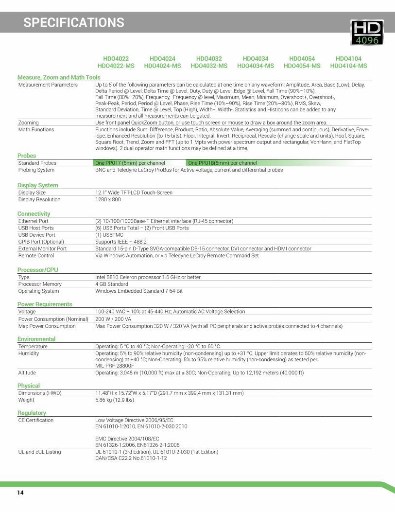
Measure, Zoom and Math ToolsMeasurement Parameters Up to 8 of the following parameters can be calculated at one time on any waveform: Amplitude, Area, Base (Low), Delay,
Delta Period @ Level, Delta Time @ Level, Duty, Duty @ Level, Edge @ Level, Fall Time (90%–10%), Fall Time (80%–20%), Frequency, Frequency @ level, Maximum, Mean, Minimum, Overshoot+, Overshoot-, Peak-Peak, Period, Period @ Level, Phase, Rise Time (10%–90%), Rise Time (20%–80%), RMS, Skew, Standard Deviation, Time @ Level, Top (High), Width+, Width-. Statistics and Histicons can be added to any measurement and all measurements can be gated.
Zooming Use front panel QuickZoom button, or use touch screen or mouse to draw a box around the zoom area.Math Functions Functions include Sum, Difference, Product, Ratio, Absolute Value, Averaging (summed and continuous), Derivative, Enve-
lope, Enhanced Resolution (to 15-bits), Floor, Integral, Invert, Reciprocal, Rescale (change scale and units), Roof, Square, Square Root, Trend, Zoom and FFT (up to 1 Mpts with power spectrum output and rectangular, VonHann, and FlatTop windows). 2 dual operator math functions may be defined at a time.
ProbesStandard Probes One PP017 (5mm) per channel One PP018(5mm) per channelProbing System BNC and Teledyne LeCroy ProBus for Active voltage, current and differential probes
Display SystemDisplay Size 12.1” Wide TFT-LCD Touch-ScreenDisplay Resolution 1280 x 800
ConnectivityEthernet Port (2) 10/100/1000Base-T Ethernet interface (RJ-45 connector)USB Host Ports (6) USB Ports Total – (2) Front USB PortsUSB Device Port (1) USBTMCGPIB Port (Optional) Supports IEEE – 488.2External Monitor Port Standard 15-pin D-Type SVGA-compatible DB-15 connector, DVI connector and HDMI connectorRemote Control Via Windows Automation, or via Teledyne LeCroy Remote Command Set
Processor/CPUType Intel B810 Celeron processor 1.6 GHz or betterProcessor Memory 4 GB StandardOperating System Windows Embedded Standard 7 64-Bit
Power RequirementsVoltage 100-240 VAC + 10% at 45-440 Hz; Automatic AC Voltage SelectionPower Consumption (Nominal) 200 W / 200 VAMax Power Consumption Max Power Consumption 320 W / 320 VA (with all PC peripherals and active probes connected to 4 channels)
EnvironmentalTemperature Operating: 5 °C to 40 °C; Non-Operating: -20 °C to 60 °CHumidity Operating: 5% to 90% relative humidity (non-condensing) up to +31 °C, Upper limit derates to 50% relative humidity (non-
condensing) at +40 °C; Non-Operating: 5% to 95% relative humidity (non-condensing) as tested per MIL-PRF-28800F
Altitude Operating: 3,048 m (10,000 ft) max at ≤ 30C; Non-Operating: Up to 12,192 meters (40,000 ft)
PhysicalDimensions (HWD) 11.48”H x 15.72”W x 5.17“D (291.7 mm x 399.4 mm x 131.31 mm) Weight 5.86 kg (12.9 lbs)
RegulatoryCE Certification Low Voltage Directive 2006/95/EC
EN 61010-1:2010, EN 61010-2-030:2010 EMC Directive 2004/108/EC EN 61326-1:2006, EN61326-2-1:2006
UL and cUL Listing UL 61010-1 (3rd Edition), UL 61010-2-030 (1st Edition) CAN/CSA C22.2 No.61010-1-12

15
ORDERING INFORMATION
Product Description Product CodeHDO4000 Oscilloscopes200 MHz, 2.5 GS/s, 2 Ch, 12.5 Mpts/Ch 12-bit HD Oscilloscope with 12.1" WXGA Touch Display
HDO4022
200 MHz, 2.5 GS/s, 4 Ch, 12.5 Mpts/Ch 12-bit HD Oscilloscope with 12.1" WXGA Touch Display
HDO4024
350 MHz, 2.5 GS/s, 2 Ch, 12.5 Mpts/Ch 12-bit HD Oscilloscope with 12.1" WXGA Touch Display
HDO4032
350 MHz, 2.5 GS/s, 4 Ch, 12.5 Mpts/Ch 12-bit HD Oscilloscope with 12.1" WXGA Touch Display
HDO4034
500 MHz, 2.5 GS/s, 4 Ch, 12.5 Mpts/Ch 12-bit HD Oscilloscope with 12.1" WXGA Touch Display
HDO4054
1 GHz, 2.5 GS/s, 4 Ch, 12.5 Mpts/Ch 12-bit HD Oscilloscope with 12.1" WXGA Touch Display
HDO4104
HDO4000-MS Mixed Signal Oscilloscopes200 MHz, 2.5 GS/s, 2+16ch, 12.5 Mpts/Ch 12-bit HD Mixed Signal Oscilloscope w/ 12.1” WXGA Color Display
HDO4022-MS
200 MHz, 2.5 GS/s, 4+16ch, 12.5 Mpts/Ch 12-bit HD Mixed Signal Oscilloscope w/ 12.1” WXGA Color Display
HDO4024-MS
350 MHz, 2.5 GS/s, 2+16ch, 12.5 Mpts/Ch 12-bit HD Mixed Signal Oscilloscope w/ 12.1” WXGA Color Display
HDO4032-MS
350 MHz, 2.5 GS/s, 4+16ch, 12.5 Mpts/Ch 12-bit HD Mixed Signal Oscilloscope w/ 12.1” WXGA Color Display
HDO4034-MS
500 MHz, 2.5 GS/s, 4+16ch, 12.5 Mpts/Ch 12-bit HD Mixed Signal Oscilloscope w/ 12.1” WXGA Color Display
HDO4054-MS
1 GHz, 2.5 GS/s, 4+16ch, 12.5 Mpts/Ch 12-bit HD Mixed Signal Oscilloscope w/ 12.1” WXGA Color Display
HDO4104-MS
Included with Standard Configurations (HDO4000 and HDO4000-MS)÷10 Passive Probe (Total of 1 Per Channel), Getting Started Guide, Anti-virus Software (Trial Version), Microsoft Windows Embedded Standard 7 P 64-Bit License, Commercial NIST Traceable Calibration with Certificate, Power Cable for the Destination Country, Protective Front Cover, 3-year Warranty
Included with HDO4000-MS16 Channel Digital Leadset, Extra Large Gripper Probe Set (Qty. 22), Ground Extenders (Qty. 20), Flexible Ground Leads (Qty. 5)
Memory Option25 Mpts/ch (50 Mpts interleaved) memory HDO4K-L
Hardware OptionsRemovable Hard Drive Package (includes removable hard drive kit and two hard drives)
HDO4K-RHD
Additional Removable Hard Drive HDO4K-RHD-02
General AccessoriesExternal GPIB Accessory USB2-GPIBSoft Carrying Case HDO4K-SOFTCASERack Mount Accessory HDO4K-RACKAccessory Pouch HDO4K-POUCH
Local Language OverlaysGerman Front Panel Overlay HDO4K-FP-GERMANFrench Front Panel Overlay HDO4K-FP-FRENCHItalian Front Panel Overlay HDO4K-FP-ITALIANSpanish Front Panel Overlay HDO4K-FP-SPANISHJapanese Front Panel Overlay HDO4K-FP-JAPANESEKorean Front Panel Overlay HDO4K-FP-KOREANChinese (Tr) Front Panel Overlay HDO4K-FP-CHNES-TRChinese (Simp) Front Panel Overlay HDO4K-FP-CHNES-SIRussian Front Panel Overlay HDO4K-FP-RUSSIAN
Software OptionsElectrical Telecom Mask Test Package HDO4K-ET-PMTSpectrum Analysis Option HDO4K-SPECTRUMPower Analysis Option HDO4K-PWR
Product Description Product CodeSerial Data OptionsARINC 429 Symbolic Decode Option HDO4K-ARINC429bus DSymbolicAudiobus Trigger and Decode Option for I2S, LJ, RJ, and TDM
HDO4K-Audiobus TD
CAN, LIN and FlexRay Trigger and Decode Option HDO4K-AUTOCAN FD Trigger and Decode Option HDO4K-CAN FDbus TDCAN Trigger and Decode Option HDO4K-CANbus TDD-PHY Decode Option HDO4K-DPHYbus DDigRF 3G Decode Option HDO4K-DigRF3Gbus DDigRF v4 Decode Option HDO4K-DigRFv4bus DENET Decode Option HDO4K-ENETbus DFlexRay Trigger and Decode Option HDO4K-FlexRaybus TDI2C, SPI and UART Trigger and Decode Option HDO4K-EMBI2C Bus Trigger and Decode Option HDO4K-I2Cbus TDLIN Trigger and Decode Option HDO4K-LINbus TDManchester Decode Option HDO4K-Manchesterbus DMIL-STD-1553 Trigger and Decode Option HDO4K-1553 TDNRZ Decode Option HDO4K-NRZbus DSENT Decode Option HDO4K-SENTbus DSPI Bus Trigger and Decode Option HDO4K-SPIbus TDSpaceWire Decode Option HDO4K-SpaceWirebus DUART and RS-232 Trigger and Decode Option HDO4K-UART-RS232bus TDUSB 2.0 Trigger and Decode Option HDO4K-USB2bus TDUSB2-HSIC Decode Option HDO4K-USB2-HSICbus D
Probes and Amplifiers250 MHz Passive Probe 10:1, 10 MΩ PP017500 MHz Passive Probe 10:1, 10 MΩ PP018Set of 4 ZS1500, 1.5 GHz, 0.9 pF, 1 MΩ High Impedance Active Probe
ZS1500-QUADPAK
Set of 4 ZS1000, 1 GHz, 0.9 pF, 1 MΩ High Impedance Active Probe
ZS1000-QUADPAK
200 MHz, 3.5 pF, 1 MΩ Active Differential Probe ZD2001 GHz, 1.0 pF Active Differential Probe, ±8 V ZD10001.5 GHz, 1.0 pF Active Differential Probe, ±8 V ZD15001kV, 25 MHz High Voltage Differential Probe HVD31021kV, 120 MHz High Voltage Differential Probe HVD31061kV, 80 MHz High Voltage Differential Probe with 6m cable HVD3106-6M1 kV, 25 MHz High Voltage Differential Probe with 2 m cable without tip Accessories
HVD3102-NOACC
1 kV, 120 MHz High Voltage Differential Probe with 2 m cable without tip Accessories
HVD3106-NOACC
2kV, 120 MHz High Voltage Differential Probe HVD32066kV, 100 MHz High Voltage Differential Probe HVD36051,400 V, 100 MHz High-Voltage Differential Probe ADP3051,400 V, 20 MHz High-Voltage Differential Probe ADP3001 Ch, 100 MHz Differential Amplifier with Precision Voltage Source
DA1855A
30 A; 100 MHz Current Probe – AC/DC; 30 Arms; 50 Apeak Pulse CP03130 A; 100 MHz High Sensitivity Current Probe – AC/DC; 30 Arms; 50 Apeak Pulse
CP031A
30 A; 50 MHz Current Probe – AC/DC; 30 Arms; 50 Apeak Pulse CP03030 A; 50 MHz High Sensitivity Current Probe – AC/DC; 30 Arms; 50 Apeak Pulse
CP030A
30 A; 50 MHz Current Probe – AC/DC; 30 Arms; 50 Apeak Pulse AP015150 A; 10 MHz Current Probe – AC/DC; 150 Arms; 500 Apeak Pulse CP150500 A; 2 MHz Current Probe – AC/DC; 500 Arms; 700 Apeak Pulse CP500Deskew Calibration Source for CP031, CP030 and AP015 DCS015100:1 400 MHz 50 MΩ 1 kV High-voltage Probe HVP12010:1/100:1 200/300 MHz, 50 MΩ High-voltage Probe 600 V/1,2 kV Max. Volt. DC
PPE1.2KV
100:1 400 MHz 50 MΩ 2 kV High-voltage Probe PPE2KV100:1 400 MHz 50 MΩ 4 kV High-voltage Probe PPE4KV1000:1 400 MHz 50 MΩ 5 kV High-voltage Probe PPE5KV1000:1 400 MHz 50 MΩ 6 kV High-voltage Probe PPE6KV
Customer Service Teledyne LeCroy oscilloscopes and probes are designed, built, and tested to ensure high reliability. In the unlikely event you experience difficulties, our digital oscilloscopes are fully warranted for three years and our probes are warranted for one year. This warranty includes: • No charge for return shipping • Long-term 7-year support• Upgrade to latest software at no charge
© 2015 Teledyne LeCroy, Inc. All rights reserved. Specifications, prices, availability, and delivery subject to change without notice. Product or brand names are trademarks or requested trademarks of their respective holders.
hdo4k-ds-16sep15
Local sales offices are located throughout the world. Visit our website to find the most convenient location.
1-800-5-LeCroy teledynelecroy.com