Embed Size (px)
Citation preview
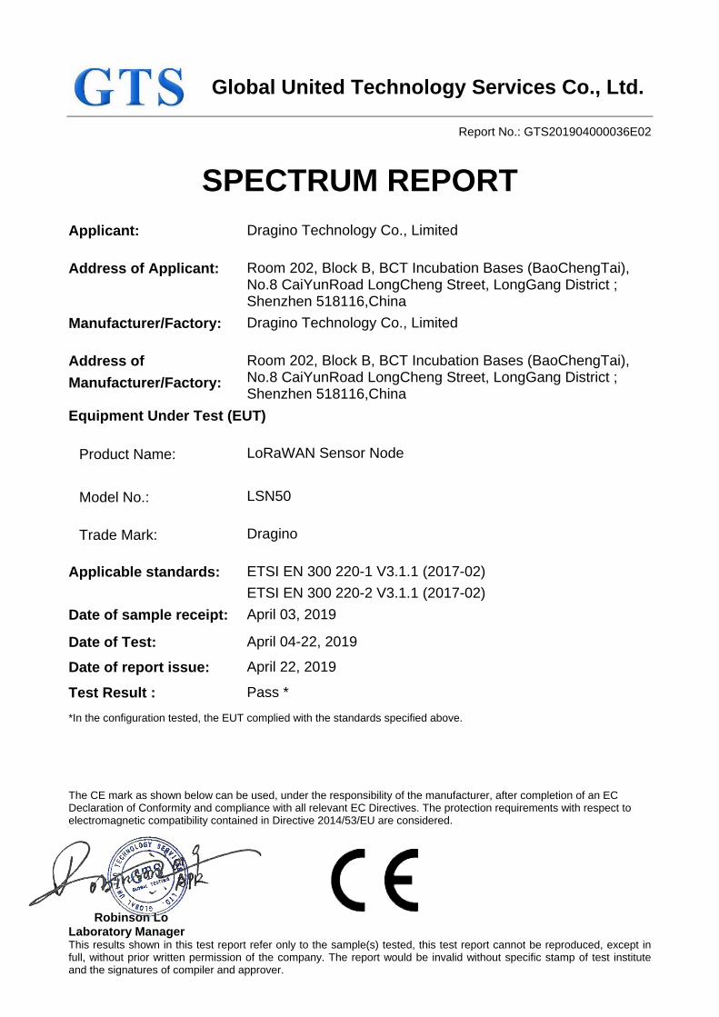
Global United Technology Services Co., Ltd.
Report No.: GTS201904000036E02
The CE mark as shown below can be used, under the responsibility of the manufacturer, after completion of an EC Declaration of Conformity and compliance with all relevant EC Directives. The protection requirements with respect to electromagnetic compatibility contained in Directive 2014/53/EU are considered.
Robinson Lo Laboratory Manager This results shown in this test report refer only to the sample(s) tested, this test report cannot be reproduced, except in full, without prior written permission of the company. The report would be invalid without specific stamp of test institute and the signatures of compiler and approver.
SPECTRUM REPORT
Applicant: Dragino Technology Co., Limited
Address of Applicant: Room 202, Block B, BCT Incubation Bases (BaoChengTai), No.8 CaiYunRoad LongCheng Street, LongGang District ; Shenzhen 518116,China
Manufacturer/Factory: Dragino Technology Co., Limited
Address of
Manufacturer/Factory:
Room 202, Block B, BCT Incubation Bases (BaoChengTai), No.8 CaiYunRoad LongCheng Street, LongGang District ; Shenzhen 518116,China
Equipment Under Test (EUT)
Product Name: LoRaWAN Sensor Node
Model No.: LSN50
Trade Mark: Dragino
Applicable standards: ETSI EN 300 220-1 V3.1.1 (2017-02)
ETSI EN 300 220-2 V3.1.1 (2017-02)
Date of sample receipt: April 03, 2019
Date of Test: April 04-22, 2019
Date of report issue: April 22, 2019
Test Result : Pass *
*In the configuration tested, the EUT complied with the standards specified above.
Report No.: GTS201904000036E02
Global United Technology Services Co., Ltd.
No. 123- 128, Tower A, Jinyuan Business Building, No.2, Laodong Industrial Zone,
Xixiang Road, Baoan District, Shenzhen, Guangdong, China
Telephone: +86 (0) 755 2779 8480 Fax: +86 (0) 755 2779 8960 Page 2 of 33
2 Version
Version No. Date Description
00 April 22, 2019 Original
Prepared By:
Date: April 22, 2019
Project Engineer
Check By: Date: April 22, 2019
Reviewer
Report No.: GTS201904000036E02
Global United Technology Services Co., Ltd.
No. 123- 128, Tower A, Jinyuan Business Building, No.2, Laodong Industrial Zone,
Xixiang Road, Baoan District, Shenzhen, Guangdong, China
Telephone: +86 (0) 755 2779 8480 Fax: +86 (0) 755 2779 8960 Page 3 of 33
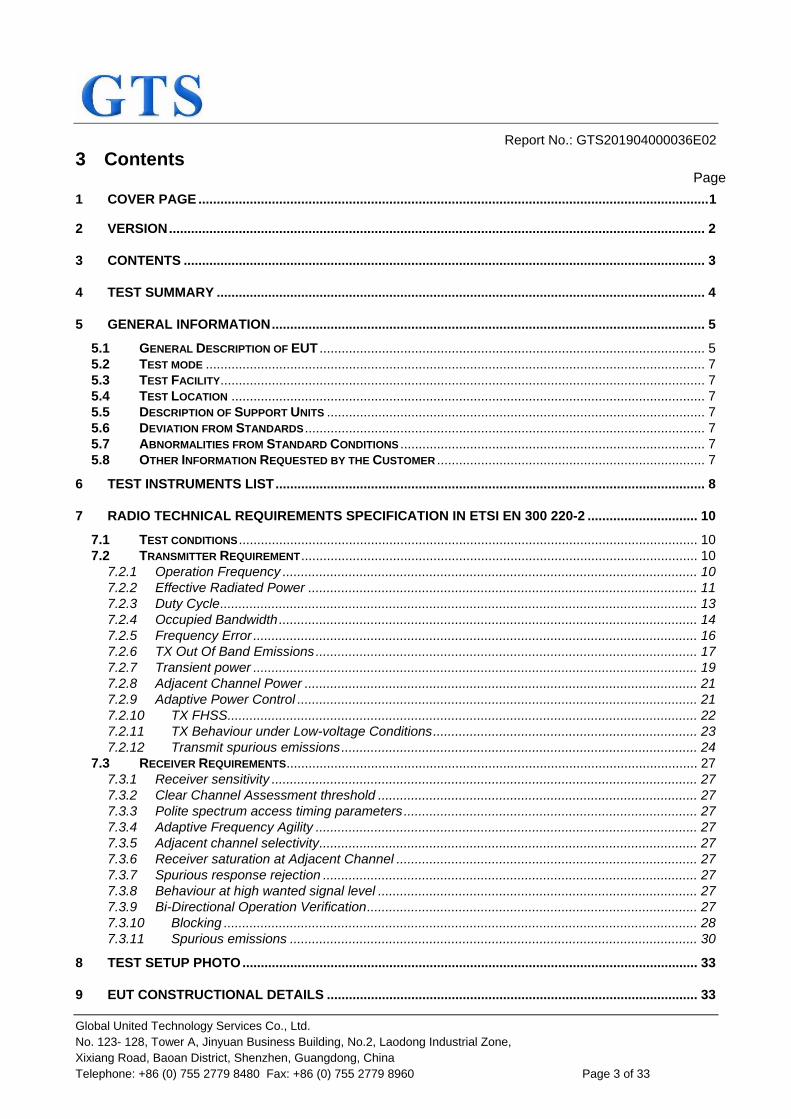
3 Contents Page
1 COVER PAGE ........................................................................................................................................... 1
2 VERSION .................................................................................................................................................. 2
3 CONTENTS .............................................................................................................................................. 3
4 TEST SUMMARY ..................................................................................................................................... 4
5 GENERAL INFORMATION ...................................................................................................................... 5
5.1 GENERAL DESCRIPTION OF EUT ......................................................................................................... 5 5.2 TEST MODE ........................................................................................................................................ 7 5.3 TEST FACILITY .................................................................................................................................... 7 5.4 TEST LOCATION ................................................................................................................................. 7 5.5 DESCRIPTION OF SUPPORT UNITS ....................................................................................................... 7 5.6 DEVIATION FROM STANDARDS ............................................................................................................. 7 5.7 ABNORMALITIES FROM STANDARD CONDITIONS ................................................................................... 7 5.8 OTHER INFORMATION REQUESTED BY THE CUSTOMER ......................................................................... 7
6 TEST INSTRUMENTS LIST ..................................................................................................................... 8
7 RADIO TECHNICAL REQUIREMENTS SPECIFICATION IN ETSI EN 300 220-2 .............................. 10
7.1 TEST CONDITIONS ............................................................................................................................. 10 7.2 TRANSMITTER REQUIREMENT ............................................................................................................ 10
7.2.1 Operation Frequency ................................................................................................................. 10 7.2.2 Effective Radiated Power .......................................................................................................... 11 7.2.3 Duty Cycle .................................................................................................................................. 13 7.2.4 Occupied Bandwidth .................................................................................................................. 14 7.2.5 Frequency Error ......................................................................................................................... 16 7.2.6 TX Out Of Band Emissions ........................................................................................................ 17 7.2.7 Transient power ......................................................................................................................... 19 7.2.8 Adjacent Channel Power ........................................................................................................... 21 7.2.9 Adaptive Power Control ............................................................................................................. 21 7.2.10 TX FHSS ................................................................................................................................ 22 7.2.11 TX Behaviour under Low-voltage Conditions ........................................................................ 23 7.2.12 Transmit spurious emissions ................................................................................................. 24
7.3 RECEIVER REQUIREMENTS ................................................................................................................ 27 7.3.1 Receiver sensitivity .................................................................................................................... 27 7.3.2 Clear Channel Assessment threshold ....................................................................................... 27 7.3.3 Polite spectrum access timing parameters ................................................................................ 27 7.3.4 Adaptive Frequency Agility ........................................................................................................ 27 7.3.5 Adjacent channel selectivity ....................................................................................................... 27 7.3.6 Receiver saturation at Adjacent Channel .................................................................................. 27 7.3.7 Spurious response rejection ...................................................................................................... 27 7.3.8 Behaviour at high wanted signal level ....................................................................................... 27 7.3.9 Bi-Directional Operation Verification .......................................................................................... 27 7.3.10 Blocking ................................................................................................................................. 28 7.3.11 Spurious emissions ............................................................................................................... 30
8 TEST SETUP PHOTO ............................................................................................................................ 33
9 EUT CONSTRUCTIONAL DETAILS ..................................................................................................... 33
Report No.: GTS201904000036E02
Global United Technology Services Co., Ltd.
No. 123- 128, Tower A, Jinyuan Business Building, No.2, Laodong Industrial Zone,
Xixiang Road, Baoan District, Shenzhen, Guangdong, China
Telephone: +86 (0) 755 2779 8480 Fax: +86 (0) 755 2779 8960 Page 4 of 33
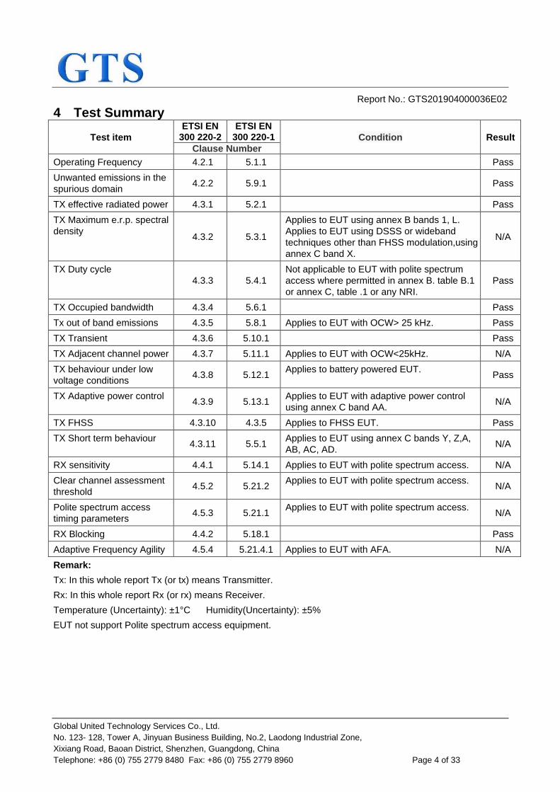
4 Test Summary
Test item
ETSI EN 300 220-2
ETSI EN 300 220-1 Condition Result
Clause Number
Operating Frequency 4.2.1 5.1.1 Pass
Unwanted emissions in the
spurious domain 4.2.2 5.9.1
Pass
TX effective radiated power 4.3.1 5.2.1 Pass
TX Maximum e.r.p. spectral
density 4.3.2 5.3.1
Applies to EUT using annex B bands 1, L.
Applies to EUT using DSSS or wideband
techniques other than FHSS modulation,using
annex C band X.
N/A
TX Duty cycle
4.3.3 5.4.1
Not applicable to EUT with polite spectrum
access where permitted in annex B. table B.1
or annex C, table .1 or any NRI.
Pass
TX Occupied bandwidth 4.3.4 5.6.1 Pass
Tx out of band emissions 4.3.5 5.8.1 Applies to EUT with OCW> 25 kHz. Pass
TX Transient 4.3.6 5.10.1 Pass
TX Adjacent channel power 4.3.7 5.11.1 Applies to EUT with OCW<25kHz. N/A
TX behaviour under low
voltage conditions 4.3.8 5.12.1
Applies to battery powered EUT. Pass
TX Adaptive power control 4.3.9 5.13.1
Applies to EUT with adaptive power control
using annex C band AA. N/A
TX FHSS 4.3.10 4.3.5 Applies to FHSS EUT. Pass
TX Short term behaviour 4.3.11 5.5.1
Applies to EUT using annex C bands Y, Z,A,
AB, AC, AD. N/A
RX sensitivity 4.4.1 5.14.1 Applies to EUT with polite spectrum access. N/A
Clear channel assessment
threshold 4.5.2 5.21.2
Applies to EUT with polite spectrum access. N/A
Polite spectrum access
timing parameters 4.5.3 5.21.1
Applies to EUT with polite spectrum access. N/A
RX Blocking 4.4.2 5.18.1 Pass
Adaptive Frequency Agility 4.5.4 5.21.4.1 Applies to EUT with AFA. N/A
Remark:
Tx: In this whole report Tx (or tx) means Transmitter.
Rx: In this whole report Rx (or rx) means Receiver.
Temperature (Uncertainty): ±1°C Humidity(Uncertainty): ±5%
EUT not support Polite spectrum access equipment.

Report No.: GTS201904000036E02
Global United Technology Services Co., Ltd.
No. 123- 128, Tower A, Jinyuan Business Building, No.2, Laodong Industrial Zone,
Xixiang Road, Baoan District, Shenzhen, Guangdong, China
Telephone: +86 (0) 755 2779 8480 Fax: +86 (0) 755 2779 8960 Page 5 of 33
5 General Information
5.1 General Description of EUT
Product Name: LoRaWAN Sensor Node
Model No.: LSN50
Operation Frequency: 863MHz~870MHz
Channel numbers: 35
Channel separation: 200kHz
Occupied bandwidth 200kHz(Declared by manufacturer)
Modulation type: FSK
Antenna type: Integral antenna
Antenna Gain: 0dBi(Declared by applicant)
Power supply: Battery: DC 3.6V

Report No.: GTS201904000036E02
Global United Technology Services Co., Ltd.
No. 123- 128, Tower A, Jinyuan Business Building, No.2, Laodong Industrial Zone,
Xixiang Road, Baoan District, Shenzhen, Guangdong, China
Telephone: +86 (0) 755 2779 8480 Fax: +86 (0) 755 2779 8960 Page 6 of 33
Operation Frequency each of channel
Channel Frequency Channel Frequency Channel Frequency Channel Frequency
1 863.1MHz 10 864.9MHz 19 866.7MHz 28 868.5MHz
2 863.3MHz 11 865.1MHz 20 866.9MHz 29 868.7MHz
3 863.5MHz 12 865.3MHz 21 867.1MHz 30 868.9MHz
4 863.7MHz 13 865.5MHz 22 867.3MHz 31 869.1MHz
5 863.9MHz 14 865.7MHz 23 867.5MHz 32 869.3MHz
6 864.1MHz 15 865.9MHz 24 867.7MHz 33 869.5MHz
7 864.3MHz 16 866.1MHz 25 867.9MHz 34 869.7MHz
8 864.5MHz 17 866.3MHz 26 868.1MHz 35 869.9MHz
9 864.7MHz 18 866.5MHz 27 868.3MHz
The test frequencies are below:
Channel Frequency
The lowest channel 863.1MHz
The middle channel 866.5MHz
The Highest channel 869.9MHz
Report No.: GTS201904000036E02
Global United Technology Services Co., Ltd.
No. 123- 128, Tower A, Jinyuan Business Building, No.2, Laodong Industrial Zone,
Xixiang Road, Baoan District, Shenzhen, Guangdong, China
Telephone: +86 (0) 755 2779 8480 Fax: +86 (0) 755 2779 8960 Page 7 of 33
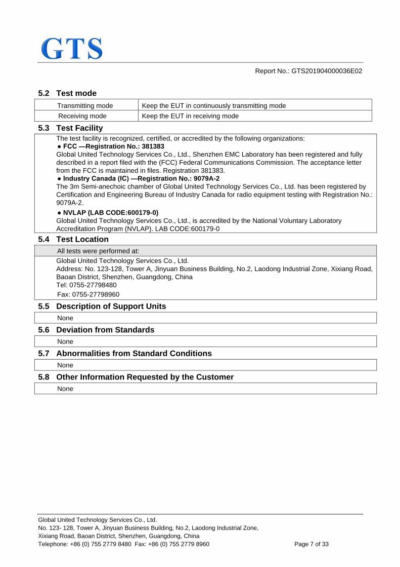
5.2 Test mode
Transmitting mode Keep the EUT in continuously transmitting mode
Receiving mode Keep the EUT in receiving mode
5.3 Test Facility
The test facility is recognized, certified, or accredited by the following organizations:
● FCC —Registration No.: 381383
Global United Technology Services Co., Ltd., Shenzhen EMC Laboratory has been registered and fully
described in a report filed with the (FCC) Federal Communications Commission. The acceptance letter
from the FCC is maintained in files. Registration 381383.
● Industry Canada (IC) —Registration No.: 9079A-2
The 3m Semi-anechoic chamber of Global United Technology Services Co., Ltd. has been registered by
Certification and Engineering Bureau of Industry Canada for radio equipment testing with Registration No.:
9079A-2.
● NVLAP (LAB CODE:600179-0)
Global United Technology Services Co., Ltd., is accredited by the National Voluntary Laboratory
Accreditation Program (NVLAP). LAB CODE:600179-0
5.4 Test Location
All tests were performed at:
Global United Technology Services Co., Ltd.
Address: No. 123-128, Tower A, Jinyuan Business Building, No.2, Laodong Industrial Zone, Xixiang Road,
Baoan District, Shenzhen, Guangdong, China
Tel: 0755-27798480
Fax: 0755-27798960
5.5 Description of Support Units
None
5.6 Deviation from Standards
None
5.7 Abnormalities from Standard Conditions
None
5.8 Other Information Requested by the Customer
None

Report No.: GTS201904000036E02
Global United Technology Services Co., Ltd.
No. 123- 128, Tower A, Jinyuan Business Building, No.2, Laodong Industrial Zone,
Xixiang Road, Baoan District, Shenzhen, Guangdong, China
Telephone: +86 (0) 755 2779 8480 Fax: +86 (0) 755 2779 8960 Page 8 of 33
6 Test Instruments list Radiated Emission:
Item Test Equipment Manufacturer Model No. Inventory
No.
Cal.Date
(mm-dd-yy)
Cal.Due date
(mm-dd-yy)
1 3m Semi- Anechoic
Chamber ZhongYu Electron 9.2(L)*6.2(W)* 6.4(H) GTS250 July. 03 2015 July. 02 2020
2 Control Room ZhongYu Electron 6.2(L)*2.5(W)* 2.4(H) GTS251 N/A N/A
3 EMI Test Receiver Rohde & Schwarz ESU26 GTS203 June. 27 2018 June. 26 2019
4 BiConiLog Antenna SCHWARZBECK
MESS-ELEKTRONIK VULB9163 GTS214 June. 27 2018 June. 26 2019
5 Double -ridged
waveguide horn
SCHWARZBECK MESS-ELEKTRONIK
BBHA 9120 D GTS208 June. 27 2018 June. 26 2019
6 Horn Antenna ETS-LINDGREN 3160 GTS217 June. 27 2018 June. 26 2019
7 EMI Test Software AUDIX E3 N/A N/A N/A
8 Coaxial Cable GTS N/A GTS213 June. 27 2018 June. 26 2019
9 Coaxial Cable GTS N/A GTS211 June. 27 2018 June. 26 2019
10 Coaxial cable GTS N/A GTS210 June. 27 2018 June. 26 2019
11 Coaxial Cable GTS N/A GTS212 June. 27 2018 June. 26 2019
12 Amplifier(100kHz-3GHz) HP 8347A GTS204 June. 27 2018 June. 26 2019
13 Amplifier(2GHz-20GHz) HP 84722A GTS206 June. 27 2018 June. 26 2019
14 Amplifier (18-26GHz) Rohde & Schwarz AFS33-18002
650-30-8P-44 GTS218 June. 27 2018 June. 26 2019
15 Band filter Amindeon 82346 GTS219 June. 27 2018 June. 26 2019
16 Power Meter Anritsu ML2495A GTS540 June. 27 2018 June. 26 2019
17 Power Sensor Anritsu MA2411B GTS541 June. 27 2018 June. 26 2019
18 Wideband Radio
Communication Tester Rohde & Schwarz CMW500 GTS575 June. 27 2018 June. 26 2019
19 Splitter Agilent 11636B GTS237 June. 27 2018 June. 26 2019
20 Loop Antenna ZHINAN ZN30900A GTS534 June. 27 2018 June. 26 2019
21 Breitband
hornantenne SCHWARZBECK BBHA 9170 GTS579 Oct. 20 2018 Oct. 19 2019
22 Amplifier TDK PA-02-02 GTS574 Oct. 20 2018 Oct. 19 2019
23 Amplifier TDK PA-02-03 GTS576 Oct. 20 2018 Oct. 19 2019
24 PSA Series Spectrum
Analyzer Rohde & Schwarz FSP GTS578 June. 27 2018 June. 26 2019

Report No.: GTS201904000036E02
Global United Technology Services Co., Ltd.
No. 123- 128, Tower A, Jinyuan Business Building, No.2, Laodong Industrial Zone,
Xixiang Road, Baoan District, Shenzhen, Guangdong, China
Telephone: +86 (0) 755 2779 8480 Fax: +86 (0) 755 2779 8960 Page 9 of 33
RF Conducted:
Item Test Equipment Manufacturer Model No. Serial No. Cal.Date
(mm-dd-yy)
Cal.Due date
(mm-dd-yy)
1 MXA Signal Analyzer Agilent N9020A GTS566 June. 27 2018 June. 26 2019
2 EMI Test Receiver R&S ESCI 7 GTS552 June. 27 2018 June. 26 2019
3 Spectrum Analyzer Agilent E4440A GTS533 June. 27 2018 June. 26 2019
4 MXG vector Signal
Generator Agilent N5182A GTS567 June. 27 2018 June. 26 2019
5 ESG Analog Signal
Generator Agilent E4428C GTS568 June. 27 2018 June. 26 2019
6 USB RF Power Sensor DARE RPR3006W GTS569 June. 27 2018 June. 26 2019
7 RF Switch Box Shongyi RFSW3003328 GTS571 June. 27 2018 June. 26 2019
8
Programmable Constant
Temp & Humi Test
Chamber
WEWON WHTH-150L-40-880 GTS572 June. 27 2018 June. 26 2019
General used equipment:
Item Test Equipment Manufacturer Model No. Inventory
No.
Cal.Date
(mm-dd-yy)
Cal.Due date
(mm-dd-yy)
1 Humidity/ Temperature
Indicator KTJ TA328 GTS243 June. 27 2018 June. 26 2019
2 Barometer ChangChun DYM3 GTS255 June. 27 2018 June. 26 2019

Report No.: GTS201904000036E02
Global United Technology Services Co., Ltd.
No. 123- 128, Tower A, Jinyuan Business Building, No.2, Laodong Industrial Zone,
Xixiang Road, Baoan District, Shenzhen, Guangdong, China
Telephone: +86 (0) 755 2779 8480 Fax: +86 (0) 755 2779 8960 Page 10 of 33
7 Radio Technical Requirements Specification in ETSI EN 300 220-2
7.1 Test conditions
Normal conditions
Ambient: Temperature.: +15°C to +35°C
relative humidity: 20 % to 75 %
Power
supply:
Battery: Nominal
AC mains source Nominal
Other power sources Nominal
Extreme conditions
Ambient: Temperature.: -20°C to +55°C
Power
supply:
Battery:
0.9 and 1.3 mutiplied for lead-acid battery 0.85 and 1.15 mutiplied for"gel-cell" type batteries 0.85 and 0.9 mutiplied for lithium and nickel-cadmium type batteries For other types it may declared by manufacturer
AC mains source ±10% of the norminal power source
Other power sources Declared by manufacturer
7.2 Transmitter Requirement
7.2.1 Operation Frequency
The Operational Frequency band(863~870MHz) was declared by the manufacturer which conforms
annexes B, C or any NRI of ETSI EN 300220-2.

Report No.: GTS201904000036E02
Global United Technology Services Co., Ltd.
No. 123- 128, Tower A, Jinyuan Business Building, No.2, Laodong Industrial Zone,
Xixiang Road, Baoan District, Shenzhen, Guangdong, China
Telephone: +86 (0) 755 2779 8480 Fax: +86 (0) 755 2779 8960 Page 11 of 33
7.2.2 Effective Radiated Power
Test Requirement: ETSI EN 300 220-2 clause 4.3.1
Test Method: ETSI EN 300 220-1 clause 5.2
Test site: Measurement Distance: 3m (Semi-Anechoic Chamber)
Receiver setup: RBW=120kHz, VBW=300kHz, Detector= peak
Limit: 25mW=14dBm (Refer to Annex B of ETSI EN 300220-2)
Test setup:
Test procedure: Substitution method was performed to determine the actual ERP emission
levels of the EUT.
The following test procedure as below:
1. On the test site as test setup graph above,the EUT shall be placed at
the 1.5m support on the turntable and in the position closest to normal
use as declared by the provider.
2. The test antenna shall be oriented initially for vertical polarization and
shall be chosen to correspond to the frequency of the transmitter.The
output of the test antenna shall be connected to the measuring
receiver.
3. The transmitter shall be switched on, if possible, without modulation
and the measuring receiver shall be tuned to the frequency of the
transmitter under test.
4. The test antenna shall be raised and lowered from 1m to 4m until a
maximum signal level is detected by the measuring receiver. Then the
turntable should be rotated through 360° in the horizontal plane, until
the maximum signal level is detected by the measuring receiver.
5. Repeat step 4 for test frequency with the test antenna polarized
horizontally.
6. Remove the transmitter and replace it with a substitution antenna (the
antenna should be half-wavelength for each frequency involved). The
center of the substitution antenna should be approximately at the
same location as the center of the transmitter. At the lower
frequencies, where the substitution antenna is very long, this will be
impossible to achieve when the antenna is polarized vertically. In such
case the lower end of the antenna should be 0.3 m above the ground.
7. Feed the substitution antenna at the transmitter end with a signal
generator connected to the antenna by means of a nonradiating cable.
Report No.: GTS201904000036E02
Global United Technology Services Co., Ltd.
No. 123- 128, Tower A, Jinyuan Business Building, No.2, Laodong Industrial Zone,
Xixiang Road, Baoan District, Shenzhen, Guangdong, China
Telephone: +86 (0) 755 2779 8480 Fax: +86 (0) 755 2779 8960 Page 12 of 33
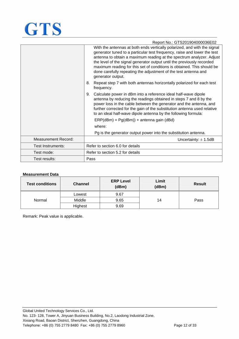
With the antennas at both ends vertically polarized, and with the signal
generator tuned to a particular test frequency, raise and lower the test
antenna to obtain a maximum reading at the spectrum analyzer. Adjust
the level of the signal generator output until the previously recorded
maximum reading for this set of conditions is obtained. This should be
done carefully repeating the adjustment of the test antenna and
generator output.
8. Repeat step 7 with both antennas horizontally polarized for each test
frequency.
9. Calculate power in dBm into a reference ideal half-wave dipole
antenna by reducing the readings obtained in steps 7 and 8 by the
power loss in the cable between the generator and the antenna, and
further corrected for the gain of the substitution antenna used relative
to an ideal half-wave dipole antenna by the following formula:
ERP(dBm) = Pg(dBm)) + antenna gain (dBd)
where:
Pg is the generator output power into the substitution antenna.
Measurement Record: Uncertainty: 1.5dB
Test Instruments: Refer to section 6.0 for details
Test mode: Refer to section 5.2 for details
Test results: Pass
Measurement Data
Test conditions Channel ERP Level
(dBm)
Limit
(dBm) Result
Normal
Lowest 9.67
14 Pass Middle 9.65
Highest 9.69
Remark: Peak value is applicable.

Report No.: GTS201904000036E02
Global United Technology Services Co., Ltd.
No. 123- 128, Tower A, Jinyuan Business Building, No.2, Laodong Industrial Zone,
Xixiang Road, Baoan District, Shenzhen, Guangdong, China
Telephone: +86 (0) 755 2779 8480 Fax: +86 (0) 755 2779 8960 Page 13 of 33
7.2.3 Duty Cycle
Test Requirement: ETSI EN 300 220-2 clause 4.3.3
Test Method: ETSI EN 300 220-1 clause 5.4
Limit: 1%
Test setup:
Test procedure: An assessment of the overall Duty Cycle shall be made for a representative period of Tobs over the observation bandwidth Fobs. Unless otherwise specified, Tobs is 1 hour and the observation bandwidth Fobs is the operational frequency band.
The representative period shall be the most active one in normal use of the device. As a guide "Normal use" is considered as representing the behaviour of the device during transmission of 99 % of transmissions generated during its operational lifetime.
Procedures such as setup, commissioning and maintenance are not considered part of normal operation.
Where an acknowledgement is used, the additional transmitter on-time from a message responder shall be declared only once whether included in the message initiator Duty Cycle or in the message responder Duty Cycle.
Center frequency: The nominal operating frequency
RBW=100kHz
VBW>=3*RBW
Span=0 Hz
Trace detector: Peak
Test Instruments: Refer to section 6.0 for details
Test mode: Refer to section 5.2 for details
Result: Pass
Measurement Data
Channel Ton time(s) Tcycle time(s) Dutycycle Limit Result
Lowest 0.15 60 0.25% 1%
Pass
Highest 0.15 60 0.25% Pass

Report No.: GTS201904000036E02
Global United Technology Services Co., Ltd.
No. 123- 128, Tower A, Jinyuan Business Building, No.2, Laodong Industrial Zone,
Xixiang Road, Baoan District, Shenzhen, Guangdong, China
Telephone: +86 (0) 755 2779 8480 Fax: +86 (0) 755 2779 8960 Page 14 of 33
7.2.4 Occupied Bandwidth
Test Requirement: ETSI EN 300 220-2 clause 4.3.4
Test Method: ETSI EN 300 220-1 clause 5.6
Receive setup:
Limit:
The Operating Channel shall be declared and shall reside entirely within the Operational Frequency Band.
The Maximum Occupied Bandwidth at 99 % shall reside entirely within the Operating Channel defined by Flow and Fhigh.
Note: For 865 MHz to 868 MHz FHSS equipment.The Maximum occupied bandwidth per hopping channel shell less or equal to 50kHz. For 863 MHz to 870 MHz FHSS equipment.The Maximum occupied bandwidth per hopping channel shell less or equal to 100kHz.
Test setup:
Test Procedure: Step 1:
Operation of the EUT shall be started, on the highest operating frequency
as declared by the manufacturer, with the appropriate test signal.
The signal attenuation shall be adjusted to ensure that the signal power
envelope is sufficiently above the noise floor of the analyser to avoid the
noise signals on either side of the power envelope being included in the
measurement.
Step 2:
When the trace is completed the peak value of the trace shall be located
and the analyser marker placed on this peak.
Step 3:
The 99 % occupied bandwidth function of the spectrum analyser shall be
used to measure the occupied bandwidth of the signal.
Measurement Record: Uncertainty: 5%
Test Instruments: Refer to section 6.0 for details
Test mode: Refer to section 5.2 for details
Test results: Pass
Report No.: GTS201904000036E02
Global United Technology Services Co., Ltd.
No. 123- 128, Tower A, Jinyuan Business Building, No.2, Laodong Industrial Zone,
Xixiang Road, Baoan District, Shenzhen, Guangdong, China
Telephone: +86 (0) 755 2779 8480 Fax: +86 (0) 755 2779 8960 Page 15 of 33
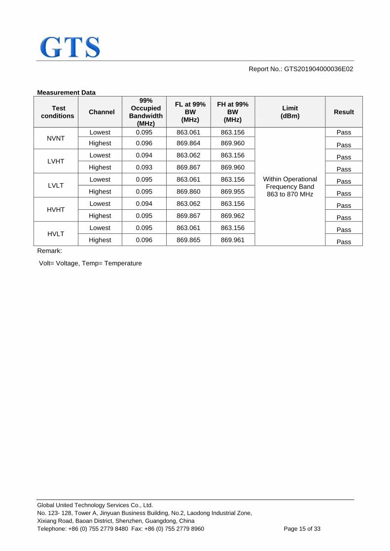
Measurement Data
Test conditions
Channel
99% Occupied
Bandwidth (MHz)
FL at 99% BW
(MHz)
FH at 99% BW
(MHz)
Limit (dBm)
Result
NVNT Lowest 0.095 863.061 863.156
Within Operational Frequency Band 863 to 870 MHz
Pass
Highest 0.096 869.864 869.960 Pass
LVHT Lowest 0.094 863.062 863.156 Pass
Highest 0.093 869.867 869.960 Pass
LVLT Lowest 0.095 863.061 863.156 Pass
Highest 0.095 869.860 869.955 Pass
HVHT Lowest 0.094 863.062 863.156 Pass
Highest 0.095 869.867 869.962 Pass
HVLT Lowest 0.095 863.061 863.156 Pass
Highest 0.096 869.865 869.961 Pass
Remark:
Volt= Voltage, Temp= Temperature

Report No.: GTS201904000036E02
Global United Technology Services Co., Ltd.
No. 123- 128, Tower A, Jinyuan Business Building, No.2, Laodong Industrial Zone,
Xixiang Road, Baoan District, Shenzhen, Guangdong, China
Telephone: +86 (0) 755 2779 8480 Fax: +86 (0) 755 2779 8960 Page 16 of 33
7.2.5 Frequency Error
Test Requirement: ETSI EN 300 220-2 clause 4.3.3
Test Method: ETSI EN 300 220-1 clause 5.7
Test setup:
Test Procedure: Step 1:
Operation of the EUT shall be started on the nominal frequency as
declared by the manufacturer under extreme high temperature and
extreme voltage conditions.
The frequency of the unmodulated carrier shall be measured and noted.
Step 2:
Operation of the EUT shall be started on the nominal frequency as
declared by the manufacturer under extreme low temperature and extreme
voltage conditions.
Measurement Record: Uncertainty: 0.5ppm
Test Instruments: Refer to section 6.0 for details
Test mode: Refer to section 5.2 for details
Test results: Pass
Measurement Data
Test conditions Channel Frequency
(MHz)
A-N
(KHz)
B-N
(KHz)
N(NTNV) Lowest 863.1 0 0
Highest 869.9 0 0
B(HTHV) Lowest 863.1 0 0
Highest 869.9 0 0
A(LTLV) Lowest 863.1 0 0
Highest 869.9 0 0
Remark:HTHV is the extreme high temperature and extreme voltage condition. LTLV is the extreme low
temperature and extreme voltage condition.
Report No.: GTS201904000036E02
Global United Technology Services Co., Ltd.
No. 123- 128, Tower A, Jinyuan Business Building, No.2, Laodong Industrial Zone,
Xixiang Road, Baoan District, Shenzhen, Guangdong, China
Telephone: +86 (0) 755 2779 8480 Fax: +86 (0) 755 2779 8960 Page 17 of 33
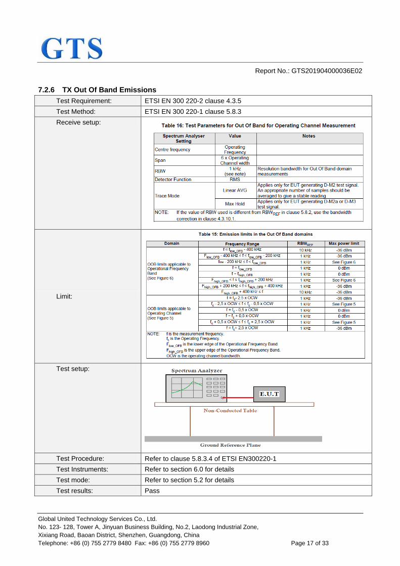
7.2.6 TX Out Of Band Emissions
Test Requirement: ETSI EN 300 220-2 clause 4.3.5
Test Method: ETSI EN 300 220-1 clause 5.8.3
Receive setup:
Limit:
Test setup:
Test Procedure: Refer to clause 5.8.3.4 of ETSI EN300220-1
Test Instruments: Refer to section 6.0 for details
Test mode: Refer to section 5.2 for details
Test results: Pass
Report No.: GTS201904000036E02
Global United Technology Services Co., Ltd.
No. 123- 128, Tower A, Jinyuan Business Building, No.2, Laodong Industrial Zone,
Xixiang Road, Baoan District, Shenzhen, Guangdong, China
Telephone: +86 (0) 755 2779 8480 Fax: +86 (0) 755 2779 8960 Page 18 of 33
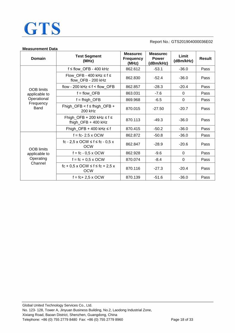
Measurement Data
Domain Test Segment
(MHz)
Measurec
Frequency
(MHz)
Measurec
Power
(dBm/kHz)
Limit
(dBm/kHz) Result
OOB limits applicable to Operational Frequency
Band
f ≤ flow_OFB - 400 kHz 862.612 -53.1 -36.0 Pass
Flow_OFB - 400 kHz ≤ f ≤
flow_OFB - 200 kHz 862.830 -52.4 -36.0 Pass
flow - 200 kHz ≤ f < flow_OFB 862.857 -28.3 -20.4 Pass
f = flow_OFB 863.031 -7.6 0 Pass
f = fhigh_OFB 869.968 -6.5 0 Pass
Fhigh_OFB < f ≤ fhigh_OFB +
200 kHz 870.015 -27.50 -20.7 Pass
Fhigh_OFB + 200 kHz ≤ f ≤
fhigh_OFB + 400 kHz 870.113 -49.3 -36.0 Pass
Fhigh_OFB + 400 kHz ≤ f 870.415 -50.2 -36.0 Pass
OOB limits applicable to
Operating
Channel
f = fc- 2.5 x OCW 862.872 -50.8 -36.0 Pass
fc - 2,5 x OCW ≤ f ≤ fc - 0,5 x
OCW 862.847 -28.9 -20.6 Pass
f = fc - 0,5 x OCW 862.928 -9.6 0 Pass
f = fc + 0,5 x OCW 870.074 -8.4 0 Pass
fc + 0,5 x OCW ≤ f ≤ fc + 2,5 x
OCW 870.116 -27.3 -20.4 Pass
f = fc+ 2,5 x OCW 870.139 -51.6 -36.0 Pass
Report No.: GTS201904000036E02
Global United Technology Services Co., Ltd.
No. 123- 128, Tower A, Jinyuan Business Building, No.2, Laodong Industrial Zone,
Xixiang Road, Baoan District, Shenzhen, Guangdong, China
Telephone: +86 (0) 755 2779 8480 Fax: +86 (0) 755 2779 8960 Page 19 of 33
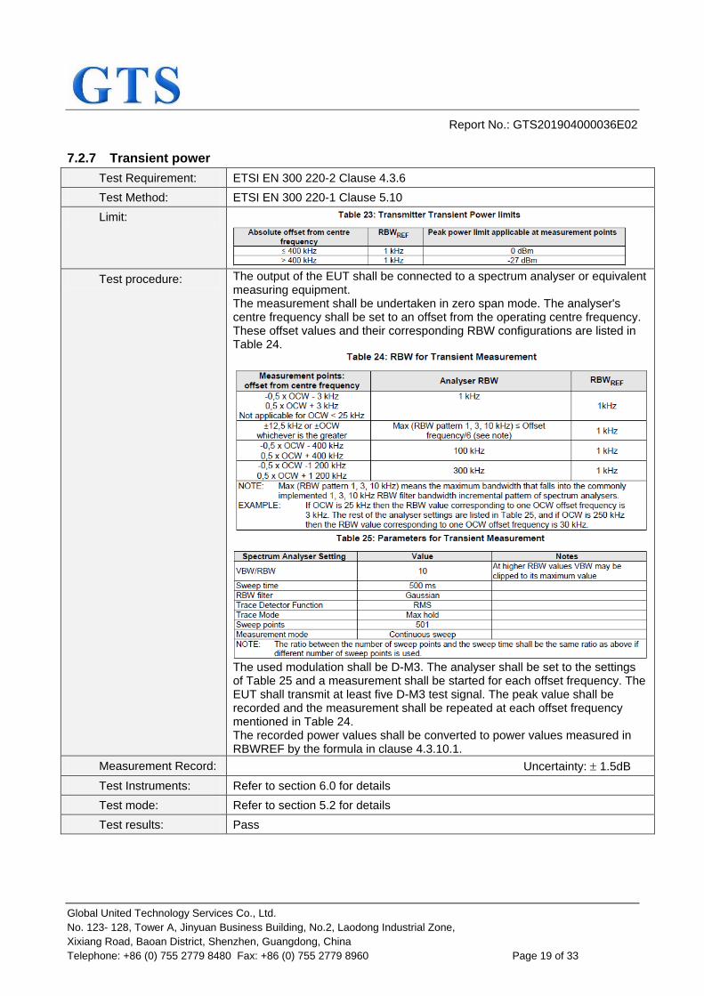
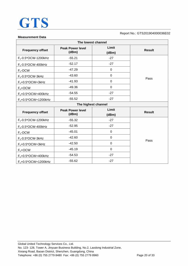
7.2.7 Transient power
Test Requirement: ETSI EN 300 220-2 Clause 4.3.6
Test Method: ETSI EN 300 220-1 Clause 5.10
Limit:
Test procedure: The output of the EUT shall be connected to a spectrum analyser or equivalent measuring equipment. The measurement shall be undertaken in zero span mode. The analyser's centre frequency shall be set to an offset from the operating centre frequency. These offset values and their corresponding RBW configurations are listed in Table 24.
The used modulation shall be D-M3. The analyser shall be set to the settings of Table 25 and a measurement shall be started for each offset frequency. The EUT shall transmit at least five D-M3 test signal. The peak value shall be recorded and the measurement shall be repeated at each offset frequency mentioned in Table 24. The recorded power values shall be converted to power values measured in RBWREF by the formula in clause 4.3.10.1.
Measurement Record: Uncertainty: 1.5dB
Test Instruments: Refer to section 6.0 for details
Test mode: Refer to section 5.2 for details
Test results: Pass
Report No.: GTS201904000036E02
Global United Technology Services Co., Ltd.
No. 123- 128, Tower A, Jinyuan Business Building, No.2, Laodong Industrial Zone,
Xixiang Road, Baoan District, Shenzhen, Guangdong, China
Telephone: +86 (0) 755 2779 8480 Fax: +86 (0) 755 2779 8960 Page 20 of 33
Measurement Data
The lowest channel
Frequency offset Peak Power level
(dBm)
Limit
(dBm) Result
Fc-0.5*OCW-1200kHz -55.21 -27
Pass
Fc-0.5*OCW-400kHz -52.17 -27
Fc-OCW -47.29 0
Fc-0.5*OCW-3kHz -43.60 0
Fc+0.5*OCW+3kHz -41.93 0
Fc+OCW -49.36 0
Fc+0.5*OCW+400kHz -54.55 -27
Fc+0.5*OCW+1200kHz -55.52 -27
The highest channel
Frequency offset Peak Power level
(dBm)
Limit
(dBm) Result
Fc-0.5*OCW-1200kHz -55.32 -27
Pass
Fc-0.5*OCW-400kHz -52.95 -27
Fc-OCW -45.01 0
Fc-0.5*OCW-3kHz -42.60 0
Fc+0.5*OCW+3kHz -42.50 0
Fc+OCW -45.19 0
Fc+0.5*OCW+400kHz -54.53 -27
Fc+0.5*OCW+1200kHz -55.62 -27
Report No.: GTS201904000036E02
Global United Technology Services Co., Ltd.
No. 123- 128, Tower A, Jinyuan Business Building, No.2, Laodong Industrial Zone,
Xixiang Road, Baoan District, Shenzhen, Guangdong, China
Telephone: +86 (0) 755 2779 8480 Fax: +86 (0) 755 2779 8960 Page 21 of 33
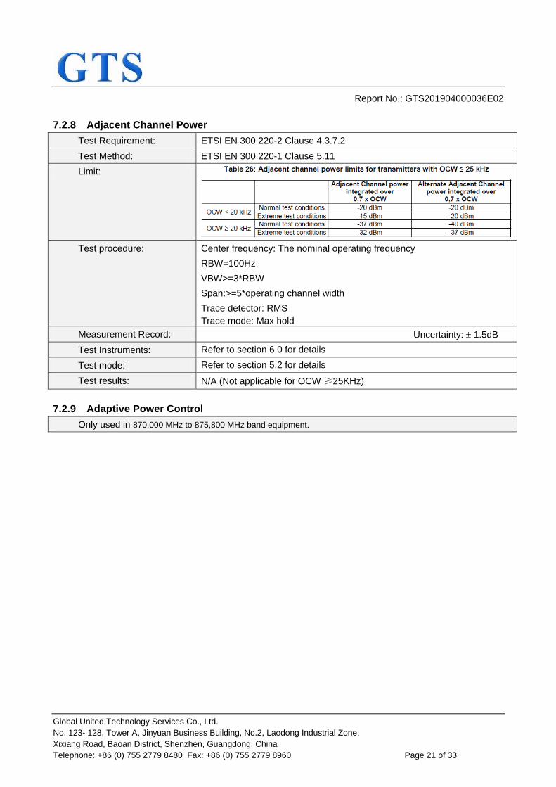
7.2.8 Adjacent Channel Power
Test Requirement: ETSI EN 300 220-2 Clause 4.3.7.2
Test Method: ETSI EN 300 220-1 Clause 5.11
Limit:
Test procedure: Center frequency: The nominal operating frequency
RBW=100Hz
VBW>=3*RBW
Span:>=5*operating channel width
Trace detector: RMS
Trace mode: Max hold
Measurement Record: Uncertainty: 1.5dB
Test Instruments: Refer to section 6.0 for details
Test mode: Refer to section 5.2 for details
Test results: N/A (Not applicable for OCW ≥25KHz)
7.2.9 Adaptive Power Control
Only used in 870,000 MHz to 875,800 MHz band equipment.
Report No.: GTS201904000036E02
Global United Technology Services Co., Ltd.
No. 123- 128, Tower A, Jinyuan Business Building, No.2, Laodong Industrial Zone,
Xixiang Road, Baoan District, Shenzhen, Guangdong, China
Telephone: +86 (0) 755 2779 8480 Fax: +86 (0) 755 2779 8960 Page 22 of 33
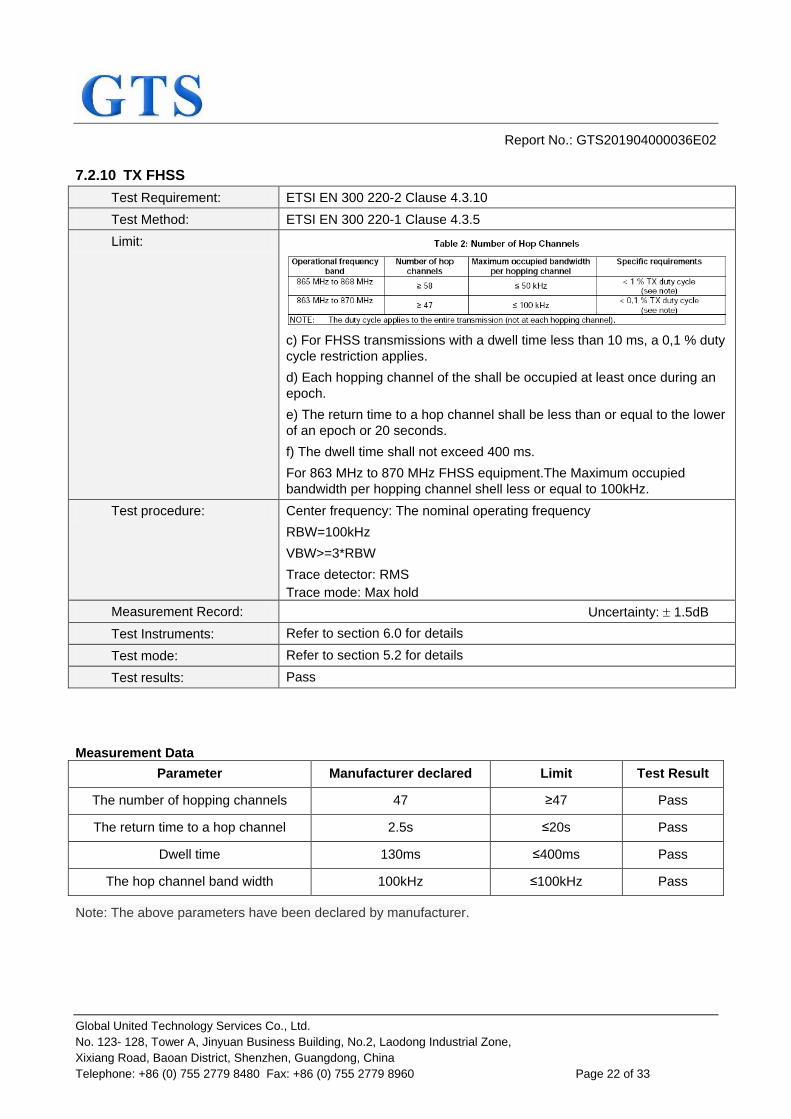
7.2.10 TX FHSS
Test Requirement: ETSI EN 300 220-2 Clause 4.3.10
Test Method: ETSI EN 300 220-1 Clause 4.3.5
Limit:
c) For FHSS transmissions with a dwell time less than 10 ms, a 0,1 % duty
cycle restriction applies.
d) Each hopping channel of the shall be occupied at least once during an
epoch.
e) The return time to a hop channel shall be less than or equal to the lower
of an epoch or 20 seconds.
f) The dwell time shall not exceed 400 ms.
For 863 MHz to 870 MHz FHSS equipment.The Maximum occupied
bandwidth per hopping channel shell less or equal to 100kHz.
Test procedure: Center frequency: The nominal operating frequency
RBW=100kHz
VBW>=3*RBW
Trace detector: RMS
Trace mode: Max hold
Measurement Record: Uncertainty: 1.5dB
Test Instruments: Refer to section 6.0 for details
Test mode: Refer to section 5.2 for details
Test results: Pass
Measurement Data
Parameter Manufacturer declared Limit Test Result
The number of hopping channels 47 ≥47 Pass
The return time to a hop channel 2.5s ≤20s Pass
Dwell time 130ms ≤400ms Pass
The hop channel band width 100kHz ≤100kHz Pass
Note: The above parameters have been declared by manufacturer.
Report No.: GTS201904000036E02
Global United Technology Services Co., Ltd.
No. 123- 128, Tower A, Jinyuan Business Building, No.2, Laodong Industrial Zone,
Xixiang Road, Baoan District, Shenzhen, Guangdong, China
Telephone: +86 (0) 755 2779 8480 Fax: +86 (0) 755 2779 8960 Page 23 of 33
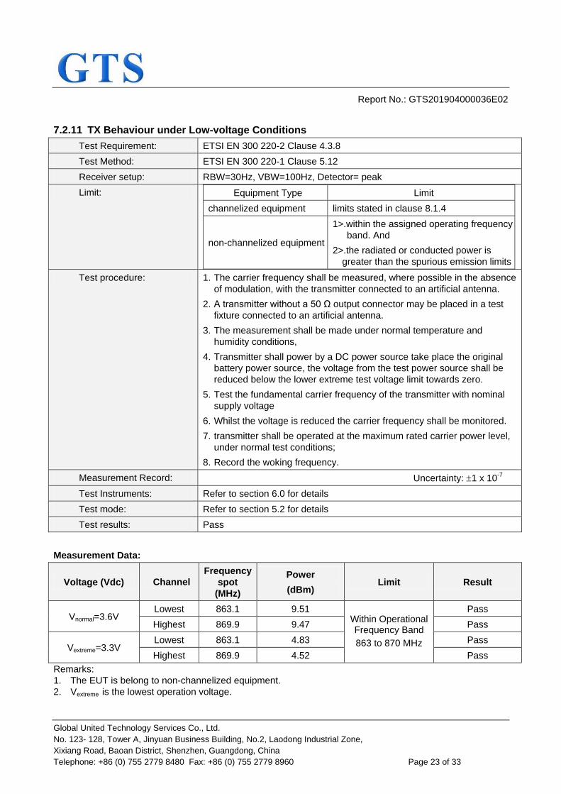
7.2.11 TX Behaviour under Low-voltage Conditions
Test Requirement: ETSI EN 300 220-2 Clause 4.3.8
Test Method: ETSI EN 300 220-1 Clause 5.12
Receiver setup: RBW=30Hz, VBW=100Hz, Detector= peak
Limit: Equipment Type Limit
channelized equipment limits stated in clause 8.1.4
non-channelized equipment
1>.within the assigned operating frequency
band. And
2>.the radiated or conducted power is
greater than the spurious emission limits
Test procedure: 1. The carrier frequency shall be measured, where possible in the absence
of modulation, with the transmitter connected to an artificial antenna.
2. A transmitter without a 50 Ω output connector may be placed in a test
fixture connected to an artificial antenna.
3. The measurement shall be made under normal temperature and
humidity conditions,
4. Transmitter shall power by a DC power source take place the original
battery power source, the voltage from the test power source shall be
reduced below the lower extreme test voltage limit towards zero.
5. Test the fundamental carrier frequency of the transmitter with nominal
supply voltage
6. Whilst the voltage is reduced the carrier frequency shall be monitored.
7. transmitter shall be operated at the maximum rated carrier power level,
under normal test conditions;
8. Record the woking frequency.
Measurement Record: Uncertainty: 1 x 10⁻⁷
Test Instruments: Refer to section 6.0 for details
Test mode: Refer to section 5.2 for details
Test results: Pass
Measurement Data:
Voltage (Vdc) Channel
Frequency
spot
(MHz)
Power
(dBm) Limit Result
Vnormal=3.6V Lowest 863.1 9.51
Within Operational Frequency Band
863 to 870 MHz
Pass
Highest 869.9 9.47 Pass
Vextreme=3.3V Lowest 863.1 4.83 Pass
Highest 869.9 4.52 Pass
Remarks:
1. The EUT is belong to non-channelized equipment.
2. Vextreme is the lowest operation voltage.
Report No.: GTS201904000036E02
Global United Technology Services Co., Ltd.
No. 123- 128, Tower A, Jinyuan Business Building, No.2, Laodong Industrial Zone,
Xixiang Road, Baoan District, Shenzhen, Guangdong, China
Telephone: +86 (0) 755 2779 8480 Fax: +86 (0) 755 2779 8960 Page 24 of 33
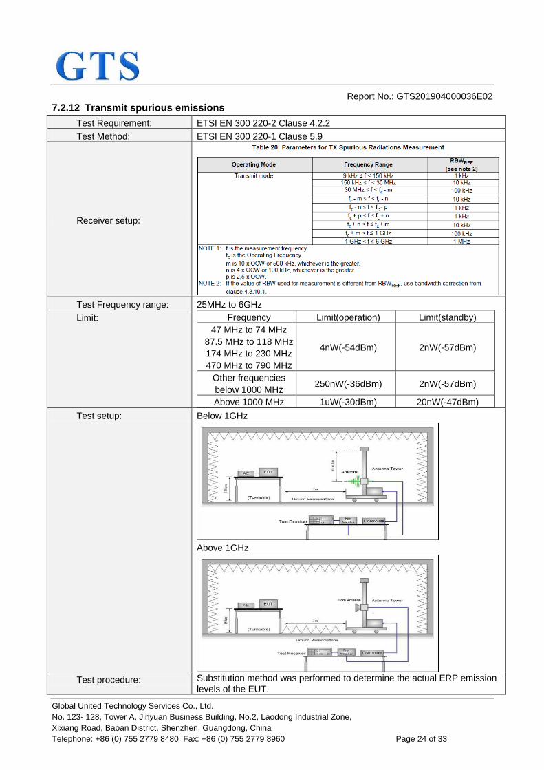
7.2.12 Transmit spurious emissions
Test Requirement: ETSI EN 300 220-2 Clause 4.2.2
Test Method: ETSI EN 300 220-1 Clause 5.9
Receiver setup:
Test Frequency range: 25MHz to 6GHz
Limit: Frequency Limit(operation) Limit(standby)
47 MHz to 74 MHz
87.5 MHz to 118 MHz
174 MHz to 230 MHz
470 MHz to 790 MHz
4nW(-54dBm) 2nW(-57dBm)
Other frequencies
below 1000 MHz 250nW(-36dBm) 2nW(-57dBm)
Above 1000 MHz 1uW(-30dBm) 20nW(-47dBm)
Test setup: Below 1GHz
Above 1GHz
Test procedure: Substitution method was performed to determine the actual ERP emission
levels of the EUT.

Report No.: GTS201904000036E02
Global United Technology Services Co., Ltd.
No. 123- 128, Tower A, Jinyuan Business Building, No.2, Laodong Industrial Zone,
Xixiang Road, Baoan District, Shenzhen, Guangdong, China
Telephone: +86 (0) 755 2779 8480 Fax: +86 (0) 755 2779 8960 Page 25 of 33
The following test procedure as below:
Below 1GHz:
1. On the test site as test setup graph above,the EUT shall be placed at
the 1.5m support on the turntable and in the position closest to normal
use as declared by the provider.
2. The test antenna shall be oriented initially for vertical polarization and
shall be chosen to correspond to the frequency of the transmitter.The
output of the test antenna shall be connected to the measuring receiver.
3. The transmitter shall be switched on, if possible, without modulation and
the measuring receiver shall be tuned to the frequency of the transmitter
under test.
4. The test antenna shall be raised and lowered from 1m to 4m until a
maximum signal level is detected by the measuring receiver. Then the
turntable should be rotated through 360° in the horizontal plane, until the
maximum signal level is detected by the measuring receiver.
5. Repeat step 4 for test frequency with the test antenna polarized
horizontally.
6. Remove the transmitter and replace it with a substitution antenna (the
antenna should be half-wavelength for each frequency involved). The
center of the substitution antenna should be approximately at the same
location as the center of the transmitter. At the lower frequencies, where
the substitution antenna is very long, this will be impossible to achieve
when the antenna is polarized vertically. In such case the lower end of
the antenna should be 0.3 m above the ground.
7. Feed the substitution antenna at the transmitter end with a signal
generator connected to the antenna by means of a nonradiating cable.
With the antennas at both ends vertically polarized, and with the signal
generator tuned to a particular test frequency, raise and lower the test
antenna to obtain a maximum reading at the spectrum analyzer. Adjust
the level of the signal generator output until the previously recorded
maximum reading for this set of conditions is obtained. This should be
done carefully repeating the adjustment of the test antenna and
generator output.
8. Repeat step 7 with both antennas horizontally polarized for each test
frequency.
9. Calculate power in dBm into a reference ideal half-wave dipole antenna
by reducing the readings obtained in steps 7 and 8 by the power loss in
the cable between the generator and the antenna, and further corrected
for the gain of the substitution antenna used relative to an ideal half-
wave dipole antenna by the following formula:
ERP(dBm) = Pg(dBm) – cable loss (dB) + antenna gain (dBd)
where:
Pg is the generator output power into the substitution antenna.
Above 1GHz:
Different between above is the test site, change from Semi- Anechoic
Chamber to fully Anechoic Chamber, and the test antenna do not need to
raise from 1 to 4m, just test in 1.5m height.
Measurement Record: Uncertainty: 6dB
Test Instruments: Refer to section 6.0 for details
Test mode: Refer to section 5.2 for details
Test results: Pass
Report No.: GTS201904000036E02
Global United Technology Services Co., Ltd.
No. 123- 128, Tower A, Jinyuan Business Building, No.2, Laodong Industrial Zone,
Xixiang Road, Baoan District, Shenzhen, Guangdong, China
Telephone: +86 (0) 755 2779 8480 Fax: +86 (0) 755 2779 8960 Page 26 of 33
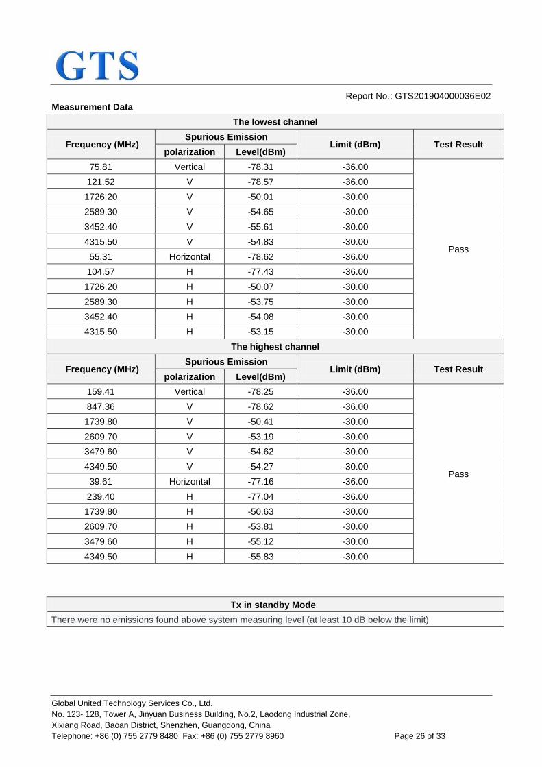
Measurement Data
The lowest channel
Frequency (MHz) Spurious Emission
Limit (dBm) Test Result polarization Level(dBm)
75.81 Vertical -78.31 -36.00
Pass
121.52 V -78.57 -36.00
1726.20 V -50.01 -30.00
2589.30 V -54.65 -30.00
3452.40 V -55.61 -30.00
4315.50 V -54.83 -30.00
55.31 Horizontal -78.62 -36.00
104.57 H -77.43 -36.00
1726.20 H -50.07 -30.00
2589.30 H -53.75 -30.00
3452.40 H -54.08 -30.00
4315.50 H -53.15 -30.00
The highest channel
Frequency (MHz) Spurious Emission
Limit (dBm) Test Result polarization Level(dBm)
159.41 Vertical -78.25 -36.00
Pass
847.36 V -78.62 -36.00
1739.80 V -50.41 -30.00
2609.70 V -53.19 -30.00
3479.60 V -54.62 -30.00
4349.50 V -54.27 -30.00
39.61 Horizontal -77.16 -36.00
239.40 H -77.04 -36.00
1739.80 H -50.63 -30.00
2609.70 H -53.81 -30.00
3479.60 H -55.12 -30.00
4349.50 H -55.83 -30.00
Tx in standby Mode
There were no emissions found above system measuring level (at least 10 dB below the limit)

Report No.: GTS201904000036E02
Global United Technology Services Co., Ltd.
No. 123- 128, Tower A, Jinyuan Business Building, No.2, Laodong Industrial Zone,
Xixiang Road, Baoan District, Shenzhen, Guangdong, China
Telephone: +86 (0) 755 2779 8480 Fax: +86 (0) 755 2779 8960 Page 27 of 33
7.3 Receiver Requirements
Receiver Classification, Table 1 of ETSI EN 300 220-1.
Rx Class Relevant Rx Clauses Risk assessment of Rx performance
1 8.3, 8.4, 8.5, 8.6
Category 1 is a high performance level of receiver. In particular to be used where the operation of a SRD may have
inherent safety of human life implications.
1.5 8.4, 8.6 Category 1.5 is an improved performance level of receiver
category 2.
2 Category 2 is standard performance level of receiver.
3 8.4, 8.6
Category 3 is a low performance level of receiver. Manufacturers have to be aware that category 3 receivers are not able to work properly in case of coexistence with some services such as a mobile radio service in adjacent bands. The manufacturer shall provide another mean to overcome the
weakness of the radio link or accept the failure.
NOTE: The receiver category should be stated in both the test report and in the user's manual for the equipment. Receiver category 3 will be withdrawn after December 31
st, 2018.
The EUT (Receiver part) belong to Category 2 with no Polite spectrum access function.
7.3.1 Receiver sensitivity
Not applicable, since the test applied to Polite spectrum access equipment.
7.3.2 Clear Channel Assessment threshold
Not applicable, since the test applied to Polite spectrum access equipment.
7.3.3 Polite spectrum access timing parameters
Not applicable, since the test applied to Polite spectrum access equipment.
7.3.4 Adaptive Frequency Agility
Not applicable, since the test applied to AFA quipment.
7.3.5 Adjacent channel selectivity
Not applicable, since the test applied to Category 1 equipment.
7.3.6 Receiver saturation at Adjacent Channel
Not applicable, since the test applied to Category 1 equipment.
7.3.7 Spurious response rejection
Not applicable, since the test applied to Category 1 equipment.
7.3.8 Behaviour at high wanted signal level
Not applicable, since the test applied to Category 1 equipment.
7.3.9 Bi-Directional Operation Verification
Not applicable, since this product is not support Bi-Directional operation function.

Report No.: GTS201904000036E02
Global United Technology Services Co., Ltd.
No. 123- 128, Tower A, Jinyuan Business Building, No.2, Laodong Industrial Zone,
Xixiang Road, Baoan District, Shenzhen, Guangdong, China
Telephone: +86 (0) 755 2779 8480 Fax: +86 (0) 755 2779 8960 Page 28 of 33
7.3.10 Blocking
Test Requirement: ETSI EN 300 220-2 Clause 4.4.2
Test Method: ETSI EN 300 220-1 clause 5.18
Limit:
A = 10 log (BWkHz / 16 kHz) BW is the receiver bandwidth
Test setup:
Test procedure: 1. Two signal generators A and B shall be connected to the receiver via a
combining network to the receiver antennaconnector.
2. Signal generator A shall be at the nominal frequency of the receiver,
with normal modulation of the wanted signal. Signal generator B shall
be unmodulated.
3. Measurements shall be carried out at frequencies of the unwanted
signal at approximately ±2 MHz and ±10 MHz, avoiding those
frequencies at which spurious responses occur.
4. Initially signal generator B shall be switched off and using signal
generator A the level which still gives sufficient response shall be
established, however, the level at the receiver input shall not be
adjusted below the sensitivity limit given in clause 8.1.4. The output
level of generator A shall then be increased by 3 dB.
5. Signal generator B is then switched on and adjusted until the wanted
criteria (see clause 8.1.1) is just exceeded. With signal generator B
settings unchanged the power into the receiver is measured by
replacing the receiver with a power meter or spectrum analyzer. This

Report No.: GTS201904000036E02
Global United Technology Services Co., Ltd.
No. 123- 128, Tower A, Jinyuan Business Building, No.2, Laodong Industrial Zone,
Xixiang Road, Baoan District, Shenzhen, Guangdong, China
Telephone: +86 (0) 755 2779 8480 Fax: +86 (0) 755 2779 8960 Page 29 of 33
level shall be recorded. Alternatively, equipment having a dedicated or
integral antenna may use a radiated measurement setup. For this, a test
site from clause A.1 shall be selected and the requirements from
clauses A.2 and A.3 apply.
6. Signal generators A and B together with a combiner shall be placed
outside the anechoic chamber and a TX test antenna shall be placed
with the EUT's antenna polarisation. The EUT shall be placed at the
location of the turntable at the orientation of the most sensitive position.
Generator A shall be set in order to reach the EUT sensitivity limit +3
dB.
7. The procedure shall be the same as for the conducted measurement.
Bloking is the difference between signal generator B and signal
generator A levels.
Test Instruments: Refer to section 6.0 for details
Test mode: Refer to section 5.2 for details
Test results: Pass
Measurement data:
The lowest channel
Frequency offset
Signal generator
A level
(dB)
Blocking level
(dB)
Limit
(dB) Result
Flow-5% of Fc -90.00 -34.00 -44.00
Pass
Flow-10MHz -90.00 -38.00 -44.00
Flow-2MHz -90.00 -45.00 -69.00
FHigh+2MHz -90.00 -45.00 -69.00
FHigh+10MHz -90.00 -37.00 -44.00
FHigh+5% of Fc -90.00 -34.00 -44.00
The highest channel
Frequency offset
Signal generator
A level
(dB)
Blocking level
(dB)
Limit
(dB) Result
Flow-5% of Fc -90.00 -35.00 -44.00
Pass
Flow-10MHz -90.00 -39.00 -44.00
Flow-2MHz -90.00 -45.00 -69.00
FHigh+2MHz -90.00 -46.00 -69.00
FHigh+10MHz -90.00 -40.00 -44.00
FHigh+5% of Fc -90.00 -36.00 -44.00
Remark: The provider declared that the receiver bandwidth is 200kHz.

Report No.: GTS201904000036E02
Global United Technology Services Co., Ltd.
No. 123- 128, Tower A, Jinyuan Business Building, No.2, Laodong Industrial Zone,
Xixiang Road, Baoan District, Shenzhen, Guangdong, China
Telephone: +86 (0) 755 2779 8480 Fax: +86 (0) 755 2779 8960 Page 30 of 33
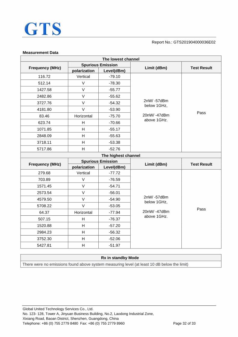
7.3.11 Spurious emissions
Test Requirement: ETSI EN 300 220-2 Clause 4.2.2
Test Method: ETSI EN 300 220-1 Clause 5.9.1.2
Receiver setup:
Test Frequency range: 25MHz to 6GHz
Limit: Frequency Limit
Other frequencies
below 1000 MHz 2nW(-57dBm)
Above 1000 MHz 20nW(-47dBm)
Test setup: Below 1GHz
Above 1GHz
Test procedure: Substitution method was performed to determine the actual ERP emission
levels of the EUT.
The following test procedure as below:

Report No.: GTS201904000036E02
Global United Technology Services Co., Ltd.
No. 123- 128, Tower A, Jinyuan Business Building, No.2, Laodong Industrial Zone,
Xixiang Road, Baoan District, Shenzhen, Guangdong, China
Telephone: +86 (0) 755 2779 8480 Fax: +86 (0) 755 2779 8960 Page 31 of 33
Below 1GHz:
1. On the test site as test setup graph above,the EUT shall be placed at the 1.5m support on the turntable and in the position closest to normal use as declared by the provider.
2. The test antenna shall be oriented initially for vertical polarization and shall be chosen to correspond to the frequency of the transmitter.The output of the test antenna shall be connected to the measuring receiver.
3. The transmitter shall be switched on, if possible, without modulation and the measuring receiver shall be tuned to the frequency of the transmitter under test.
4. The test antenna shall be raised and lowered from 1m to 4m until a maximum signal level is detected by the measuring receiver. Then the turntable should be rotated through 360° in the horizontal plane, until the maximum signal level is detected by the measuring receiver.
5. Repeat step 4 for test frequency with the test antenna polarized horizontally.
6. Remove the transmitter and replace it with a substitution antenna (the antenna should be half-wavelength for each frequency involved). The center of the substitution antenna should be approximately at the same location as the center of the transmitter. At the lower frequencies, where the substitution antenna is very long, this will be impossible to achieve when the antenna is polarized vertically. In such case the lower end of the antenna should be 0.3 m above the ground.
7. Feed the substitution antenna at the transmitter end with a signal generator connected to the antenna by means of a nonradiating cable. With the antennas at both ends vertically polarized, and with the signal generator tuned to a particular test frequency, raise and lower the test antenna to obtain a maximum reading at the spectrum analyzer. Adjust the level of the signal generator output until the previously recorded maximum reading for this set of conditions is obtained. This should be done carefully repeating the adjustment of the test antenna and generator output.
8. Repeat step 7 with both antennas horizontally polarized for each test frequency.
9. Calculate power in dBm into a reference ideal half-wave dipole antenna by reducing the readings obtained in steps 7 and 8 by the power loss in the cable between the generator and the antenna, and further corrected for the gain of the substitution antenna used relative to an ideal half-wave dipole antenna by the following formula:
ERP(dBm) = Pg(dBm) – cable loss (dB) + antenna gain (dBd)
where:
Pg is the generator output power into the substitution antenna.
Above 1GHz:
Different between above is the test site, change from Semi- Anechoic Chamber to fully Anechoic Chamber, and the test antenna do not need to raise from 1 to 4m, just test in 1.5m height.
Measurement Record: Uncertainty: 6dB
Test Instruments: Refer to section 6.0 for details
Test mode: Refer to section 5.2 for details
Test results: Pass
Report No.: GTS201904000036E02
Global United Technology Services Co., Ltd.
No. 123- 128, Tower A, Jinyuan Business Building, No.2, Laodong Industrial Zone,
Xixiang Road, Baoan District, Shenzhen, Guangdong, China
Telephone: +86 (0) 755 2779 8480 Fax: +86 (0) 755 2779 8960 Page 32 of 33
Measurement Data
The lowest channel
Frequency (MHz) Spurious Emission
Limit (dBm) Test Result polarization Level(dBm)
116.72 Vertical -79.10
2nW/ -57dBm
below 1GHz,
20nW/ -47dBm
above 1GHz.
Pass
512.14 V -78.30
1427.58 V -55.77
2482.86 V -55.62
3727.76 V -54.32
4181.80 V -53.90
83.46 Horizontal -75.70
623.74 H -70.66
1071.85 H -55.17
2848.09 H -55.63
3718.11 H -53.38
5717.86 H -52.76
The highest channel
Frequency (MHz) Spurious Emission
Limit (dBm) Test Result polarization Level(dBm)
279.68 Vertical -77.72
2nW/ -57dBm
below 1GHz,
20nW/ -47dBm
above 1GHz.
Pass
703.89 V -76.59
1571.45 V -54.71
2573.54 V -56.01
4579.50 V -54.90
5708.22 V -53.05
64.37 Horizontal -77.94
507.15 H -76.37
1520.88 H -57.20
2984.23 H -56.32
3752.30 H -52.06
5427.81 H -51.97
Rx in standby Mode
There were no emissions found above system measuring level (at least 10 dB below the limit)

Report No.: GTS201904000036E02
Global United Technology Services Co., Ltd.
No. 123- 128, Tower A, Jinyuan Business Building, No.2, Laodong Industrial Zone,
Xixiang Road, Baoan District, Shenzhen, Guangdong, China
Telephone: +86 (0) 755 2779 8480 Fax: +86 (0) 755 2779 8960 Page 33 of 33
8 Test Setup Photo
Reference to the appendix I for details.
9 EUT Constructional Details
Reference to the appendix II for details.
------End------