Embed Size (px)
Citation preview

Use of SF6 insulating gas in ZX-Switchgear
Gas-insulated medium voltage switchgear
Manual for installation and operation HB 605/05 en

2 | Manual: Use of SF6 insulating gas in ZX-switchgear HB 605 en - Revision 05
Manual: Use of SF6 insulating gas in ZX-switchgear HB 605 en - Revision 05 3
Your safety first - always!
That‘s why our instruction manual begins with these recommendations:
− Operate the switchgear as prescribed for its intended purpose.
− Ensure that the technical data on the name plate and in the specification are not exceeded during operation of the switch-
gear.
− Only install the switchgear in enclosed rooms suitable for electrical equipment.
− With the aim of a smooth installation sequence and ensuring a high quality standard, have installation at site performed by
specially trained personnel or managed and supervised by the ABB Service Department.
− Ensure that installation, operation and maintenance are only performed by specialist electricians familiar with this manual.
− Comply in full with the legally recognized standards (IEC / DIN EN), the connection conditions of the local electrical utility
and the applicable safety at work regulations.
− Follow the instructions in the documentation when performing any work on switching devices and switchgear.
− Keep all documentation accessible to all persons concerned with installation, operation and maintenance.
− The user’s personnel bear unlimited responsibility in all matters affecting safety at work and the correct handling of the
switchgear in accordance with EN 50110 and national regulations.
− Always observe the five safety rules set out in EN 50110 on establishing and securing the off-circuit condition at the place
of work for the duration of work on the switchgear. Gas-insulated switchgear are notable for maximum safety, as the circuit-
breaker performs the earthing switch function in conjunction with the three position disconnector. The sequence of safety
rules therefore deviates from that proposed in the standard as follows:
Isolate,
Check the off-circuit condition,
Earth and short-circuit,
Secure to prevent reconnection,
Cover or guard off adjacent live parts.
If you have any further questions on this manual, the members of our fi eld organization will be pleased to provide the required infor-
mation.
4 | Manual: Use of SF6 insulating gas in ZX-switchgear HB 605 en - Revision 05
Content
Page
1. General 6
1.1 General information on sulphur hexafl uoride (SF6) 6
1.2 Infl uence of SF6 on the environment 6
1.3 Voluntary commitment 6
2. Insulating gas systems of ZX switchgear 7
2.1 Switchgear type ZX0 block design 7
2.2 Switchgear type ZX0.2 8
2.3 Switchgear type ZX1.2 9
2.4 Switchgear type ZX2 10
2.5 Gas monitoring 11
2.5.1 Gas monitoring with density sensors 11
2.5.2 Gas monitoring with a pressure gauge 11
2.6 Drying agent 11
3 Handling sulphur hexafl uoride (SF6) 12
3.1 Safety at work 12
3.2 Hazards to health 12
4 Gas work 13
4.1 General notes 13
4.2 Minimum requirements and the conditions for the certifi cation of personnel recovering SF6 13
4.3 Delivery form of SF6 in gas cylinders 15
4.4 Notes on the fi ller valve 15
4.5 Topping up insulating gas 16
4.6 Removal of insulating gas 16
4.7 Filling compartments with insulating gas 17
4.8 Testing of insulating gas 17
4.9 Handling of the drying agent 17
5 Actions at the end of the switchgear service life 18
6 Technical data 19
6.1 Ratings 19
6.2 Insulating gas capacities 20
6.3 Number of drying agent bags 21
7 Sample works instructions 22
Appendix A Safety Data Sheet Sulphur Hexafl uoride 25
Manual: Use of SF6 insulating gas in ZX-switchgear HB 605 en - Revision 05 5
This manual serves as a supplement to the manuals for ZX0 block
design, ZX1.2 and ZX2 switchgear. It contains safety and environ-
mental topics concerning the insulating gas and describes the use
of insulating gas and its handling.
Fundamental notes on this manual
Read the relevant sections of this manual through in full before
performing work, so as to ensure correct handling.
Paragraphs in this manual are marked in accordance with their
signifi cance. The markings mean the following:
Take particular account of the relevant standards listed below. Observe the national technical specifications and the accident prevention
regulations of the country in which the switchgear is operated.
IEC 60376 Specification of technical grade sulphur hexafluoride (SF6) for use in electrical equipment
IEC 60480Guidelines for the checking and treatment of sulphur hexafluoride (SF
6) taken from electrical equipment and
specification for its re-use
IEC 62271-4High-voltage switchgear and controlgear –
Use and handling of sulphur hexafluoride (SF6)
National technical accident prevention regulations e.g. for electrical systems and equipment, SF6 installations and requirements for pressurized gas
bottles.
Hazard warning, meaning in this manual that death
or serious injury and considerable damage may oc-
cur if the actions described are not performed.
Important note, meaning in this manual that injury
and damage may occur if the actions described are
not performed.

6 | Manual: Use of SF6 insulating gas in ZX-switchgear HB 605 en - Revision 05
1 General
ZX panels contain sulphur hexafl uoride gas (chemical formula SF6)
as the insulating medium. After leakage testing and evacuation at
the works, the gas compartments are fi lled with SF6 up to the rat-
ed fi lling pressure for insulation, and delivered to site in that condi-
tion, where they can as a rule be installed without any gas work.
The gas compartments meet the requirements for sealed pressure
systems to IEC 62271-1. No further gas or vacuum treatment is
necessary during the expected service life of the switchgear. The
leakage rate of the switchgear is less than 0.1 % per year.
The SF6 gas density in the gas compartments is permanently
monitored during operation of the switchgear by means of density
sensors 1) (= temperature-compensated pressure sensors). In the
most unlikely event of leakage from a gas compartment, a signal
is issued when the warning signal for insulation level is reached
(see technical data).
1.1 General information on
sulphur hexafluoride (SF6)
SF6 is an inorganic chemical compound of the elements sulphur
and fl uorine. It is a non-toxic, colourless and odourless inert gas.
As SF6 is heavier than air it displaces the oxygen in the air if it is
inadvertently set free. The dielectric strength of SF6 is 2.5 times
that of air. It is therefore excellently suitable for use as an insulating
gas in electrical equipment.
SF6 is approximately fi ve times heavier than air and can accumu-
late in low-lying spaces. If large quantities escape into the working
area, SF6 leads to a displacement of oxygen from the air people
breathe (danger of asphyxiation). SF6 concentrations of over 19 %
by volume reduce the oxygen content of the air to below 17 % by
volume and special protective measures are therefore required.
The use of SF6 has made it possible to construct new, more ef-
fi cient switchgear. The change from conventional insulation to the
non-combustible, chemically inactive and non-toxic heavy gas
sulphur hexafl uoride has led to considerable savings in space and
materials, and to greater safety of the systems.
1.2 Influence of SF6 on the environment
The high infrared absorption of SF6 and its long life in the environ-
ment are the reasons for its high GWP (Global Warming Potential),
which, according to the latest IPCC Report (IPCC: Intergovern-
mental Panel on Climate Change) is 22200 times higher than that
of CO2 (carbon dioxide).
The GWP of a greenhouse gas indicates the amount by which a
certain quantity of the gas released into the atmosphere contrib-
utes more or less strongly to the greenhouse effect than the same
quantity of CO2. The GWP is based on the average warming effect
over a period of 100 years. CO2 has a GWP of 1.
The total contribution of SF6 to the global greenhouse effect is ap-
prox. 0.2 %.
The GWP of SF6 represents only one indicator of the environmen-
tal impact of electrical equipment containing SF6. Life Cycle As-
sessments 2) show that the use of equipment containing SF6 also
allows the CO2 emissions of the entire system to be reduced as a
result of the reduction in network losses.
1.3 Voluntary commitment
ABB AG in Germany has, together with other manufacturers and
operators in the associations VIK, ZVEI and VDN which represent
the power engineering industry in Germany, committed itself in a
voluntary agreement on electrical equipment > 1 kV in the Federal
Republic of Germany to avoiding SF6 emissions wherever possible.
The agreement sets out sustainable strategies, including both the
responsible handling of equipment containing SF6 on decommis-
sioning and the entire process of return, recovery and reuse.
The efforts of the industry are directed at maintaining a closed
life cycle. Especial importance is attached to the environmentally
sound recycling of the individual components of electrical equip-
ment and to reuse of the normally reusable sulphur hexafl uoride.
All the businesses involved in the life cycle process must therefore
comply with the voluntary commitment.
Recovered SF6 is as a rule either reused directly at site, or re-
turned in a closed system to the manufacturer for reuse.
1) In the case of the ZX0 without auxiliary voltage, pressure gauges are used2) E.g. the Life Cycle Assessment “SF
6 GIS Technology in Power Distribution – Medium Voltage” by various manufacturers and operators of
gas-insulated switchgear in 2003
Manual: Use of SF6 insulating gas in ZX-switchgear HB 605 en - Revision 05 7
2 Insulating gas systems of
ZX switchgear
The fundamental structure of the insulating gas system depends
on the switchgear type. The insulating gas systems of switchgear
types ZX0 in block design, ZX0.2, ZX1.2 and ZX2 are presented
below.
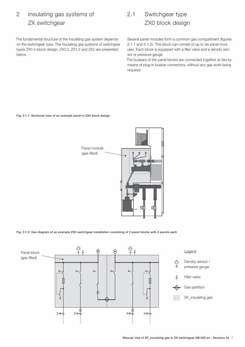
Fig. 2.1.1: Sectional view of an example panel in ZX0 block design
Fig. 2.1.2: Gas diagram of an example ZX0 switchgear installation consisting of 2 panel blocks with 3 panels each
Legend
Density sensor /
pressure gauge
Filler valve
Gas partition
SF6 insulating gas
2.1 Switchgear type
ZX0 block design
Several panel modules form a common gas compartment (fi gures
2.1.1 and 2.1.2). This block can consist of up to six panel mod-
ules. Each block is equipped with a fi ller valve and a density sen-
sor or pressure gauge.
The busbars of the panel blocks are connected together at site by
means of plug-in busbar connectors, without any gas work being
required.
Panel module
(gas-fi lled)
Panel block
(gas-fi lled)
8 | Manual: Use of SF6 insulating gas in ZX-switchgear HB 605 en - Revision 05
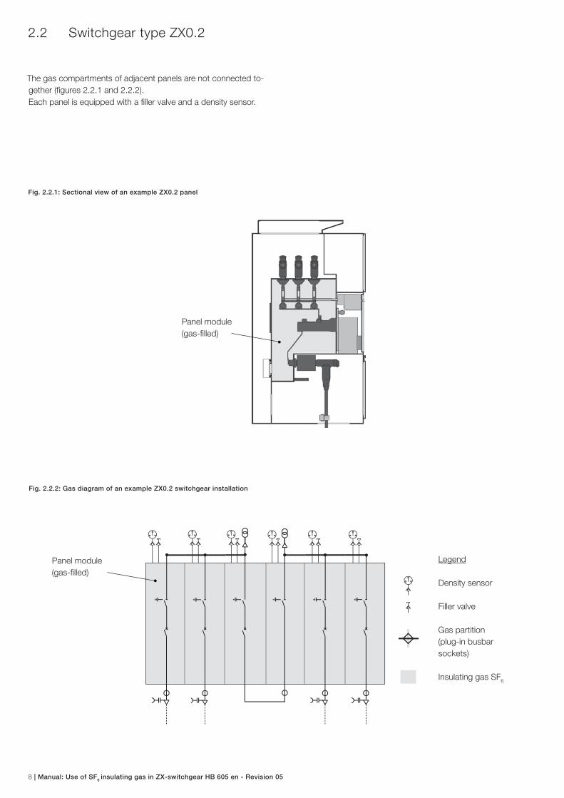
2.2 Switchgear type ZX0.2
The gas compartments of adjacent panels are not connected to-
gether (fi gures 2.2.1 and 2.2.2).
Each panel is equipped with a fi ller valve and a density sensor.
Fig. 2.2.1: Sectional view of an example ZX0.2 panel
Fig. 2.2.2: Gas diagram of an example ZX0.2 switchgear installation
Panel module
(gas-fi lled)
Panel module
(gas-fi lled)
Legend
Density sensor
Filler valve
Gas partition
(plug-in busbar
sockets)
Insulating gas SF6
Manual: Use of SF6 insulating gas in ZX-switchgear HB 605 en - Revision 05 9
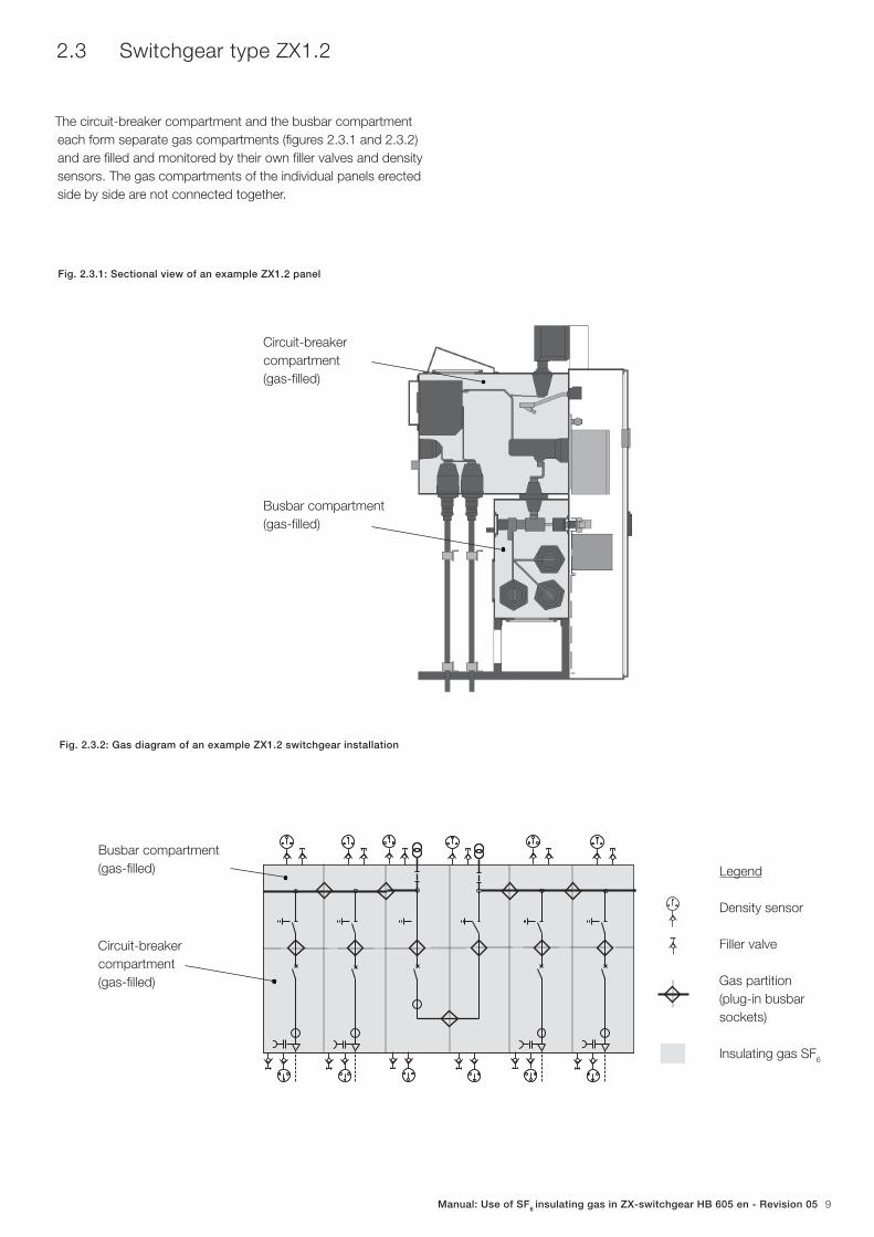
Fig. 2.3.1: Sectional view of an example ZX1.2 panel
Fig. 2.3.2: Gas diagram of an example ZX1.2 switchgear installation
2.3 Switchgear type ZX1.2
The circuit-breaker compartment and the busbar compartment
each form separate gas compartments (fi gures 2.3.1 and 2.3.2)
and are fi lled and monitored by their own fi ller valves and density
sensors. The gas compartments of the individual panels erected
side by side are not connected together.
Circuit-breaker
compartment
(gas-fi lled)
Busbar compartment
(gas-fi lled)
Legend
Density sensor
Filler valve
Gas partition
(plug-in busbar
sockets)
Insulating gas SF6
Busbar compartment
(gas-fi lled)
Circuit-breaker
compartment
(gas-fi lled)
10 | Manual: Use of SF6 insulating gas in ZX-switchgear HB 605 en - Revision 05
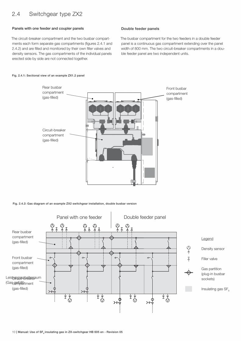
Fig. 2.4.1: Sectional view of an example ZX1.2 panel
Fig. 2.4.2: Gas diagram of an example ZX2 switchgear installation, double busbar version
2.4 Switchgear type ZX2
Panels with one feeder and coupler panels
The circuit-breaker compartment and the two busbar compart-
ments each form separate gas compartments (fi gures 2.4.1 and
2.4.2) and are fi lled and monitored by their own fi ller valves and
density sensors. The gas compartments of the individual panels
erected side by side are not connected together.
Legend
Density sensor
Filler valve
Gas partition
(plug-in busbar
sockets)
Insulating gas SF6
Circuit-breaker
compartment
(gas-fi lled)
Rear busbar
compartment
(gas-fi lled)
Front busbar
compartment
(gas-fi lled)
Rear busbar
compartment
(gas-fi lled)
Front busbar
compartment
(gas-fi lled)
Circuit-breaker
compartment
(gas-fi lled)
Double feeder panelPanel with one feeder
Double feeder panels
The busbar compartment for the two feeders in a double feeder
panel is a continuous gas compartment extending over the panel
width of 800 mm. The two circuit-breaker compartments in a dou-
ble feeder panel are two independent units.
Leistungsschalterraum
(Gas gefüllt)
Manual: Use of SF6 insulating gas in ZX-switchgear HB 605 en - Revision 05 11
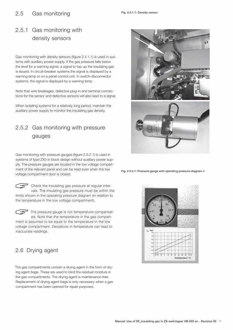
2.5 Gas monitoring
2.5.1 Gas monitoring with
density sensors
Gas monitoring with density sensors (fi gure 2.4.1.1) is used in sys-
tems with auxiliary power supply. If the gas pressure falls below
the level for a warning signal, a signal to top up the insulating gas
is issued. In circuit-breaker systems the signal is displayed by a
warning lamp or on a panel control unit. In switch-disconnector
systems, the signal is displayed by a warning lamp.
Note that wire breakages, defective plug-in and terminal connec-
tions for the sensor and defective sensors will also lead to a signal.
When isolating systems for a relatively long period, maintain the
auxiliary power supply to monitor the insulating gas density.
2.5.2 Gas monitoring with pressure
gauges
Gas monitoring with pressure gauges (fi gure 2.5.2.1) is used in
systems of type ZX0 in block design without auxiliary power sup-
ply. The pressure gauges are located in the low voltage compart-
ment of the relevant panel and can be read even when the low
voltage compartment door is closed.
Check the insulating gas pressure at regular inter-
vals. The insulating gas pressure must be within the
limits shown in the operating pressure diagram (in relation to
the temperature in the low voltage compartment).
The pressure gauge is not temperature-compensat-
ed. Note that the temperature in the gas compart-
ment is assumed to be equal to the temperature in the low
voltage compartment. Deviations in temperature can lead to
inaccurate readings.
2.6 Drying agent
The gas compartments contain a drying agent in the form of dry-
ing agent bags. These are used to bind the residual moisture in
the gas compartments. The drying agent is maintenance-free.
Replacement of drying agent bags is only necessary when a gas
compartment has been opened for repair purposes.
Fig. 2.5.1.1: Density sensor
Fig. 2.5.2.1: Pressure gauge with operating pressure diagram.1:
12 | Manual: Use of SF6 insulating gas in ZX-switchgear HB 605 en - Revision 05
3 Handling sulphur hexafluoride (SF6)
3.1 Safety at work
Observe IEC 62271-4 and the accident prevention regulations
issued by the relevant professional bodies. Keep these accident
prevention regulations accessible to all staff who perform work on
SF6 gas compartments.
Compile instructions for work on SF6 gas compartments and
display them at a clearly visible location in the switchgear room.
Sample instructions can be found at the end of this document.
Use the instruction sheets to instruct staff performing work on
SF6 gas compartments on the possible hazards and protection
required before they commence their activities and then at least
once each year.
3.2 Hazards to health
− Pure SF6 is non-toxic, colourless and odourless.
− The limit for SF6 in air is 1000 ml / m3 or 6100 mg / m3.
− Observe IEC 62271-4.
SF6 is around five times heavier than air. SF
6 there-
fore displaces the oxygen in the air we breathe. It
can lead to a risk of asphyxiation in opened, non-
ventilated SF6 gas compartments, or when relatively large
quantities of SF6 escape from SF
6 gas compartments or
pressure vessels and there is insufficient ventilation at the
floor level of constricted, enclosed switchgear rooms or
spaces beneath switchgear rooms, e.g. basements or cable
ducts. If SF6 accumulates in low-lying spaces, remove it im-
mediately.
Avoid generating heat, e.g. by smoking or performing welding
work, when handling SF6.
SF6 decomposition products are created by arc faults in an SF
6
gas compartment. These decomposition products can be toxic or
hazardous to health when inhaled, swallowed or allowed to come
into contact with the skin, or can cause irritation or even possibly
acid burns to the eyes, respiratory organs or skin.
Decomposition products can be detected at an early stage by a
pungent, unpleasant odour (like rotten eggs).
Do not enter the switchgear room when an arc fault
has occurred, or leave it immediately. Ventilate the
switchgear room sufficiently before entering it with-
out protective equipment.
Details of fi rst aid procedures after inhaling or contact with SF6
decomposition products can be found in the technical report
IEC 62271-4.
Do not smoke, eat, drink or weld while performing cleaning work.
Observe the requirements for wearing protective equipment as set
out in IEC 62271-4 and national regulations.
Manual: Use of SF6 insulating gas in ZX-switchgear HB 605 en - Revision 05 13
4 Gas work
Panels of the ZX range are tested for gas-tightness at the works
(leakage rate measurement by the integrated leakage testing sys-
tem) and then fi lled with insulating gas. Topping up of insulating
gas during the expected service life of the switchgear is therefore
not necessary.
As a result of the plug-in busbar technology, no gas work is re-
quired during installation at site in the majority of cases.
Gas work during installation of the switchgear is only necessary
when
− heat sinks are used (panels with Ir > 2000 A and cooling
with heat sinks; the heat sinks are fitted at site and filled
with SF6),
− the panels have been transported by air freight,
− application of integrated busbarmetering equipped with
isolating device at ZX2-switchgear.
4.1 General notes
− We recommend calling in ABB after-sales service personnel
for work in gas compartments.
− Never discharge SF6 into the atmosphere.
− Replacement of the insulating gas in the system is not nec-
essary. SF6 can be considered as good as new even after
long periods of use as an insulating gas.
− A two stage vacuum pump with a delivery of at least
6 m3 / h is required for evacuation of a gas compartment
prior to filling with insulating gas.
− An SF6 gas filling unit is required for filling and topping up
the insulating gas.
− A leakage tester and a dew point measuring instrument are
required for filling of insulating gas when the gas compart-
ment has previously been opened.
− A gas service unit with the facility for recovery of the gas is
required for removal of SF6.
− Protect the gas hoses on the equipment from moisture.
Use hose fittings with non-return valves to prevent the in-
gress of humid air into the hoses. Close off the hose fittings
with caps after use.
− Limit the ingress of ambient air during work on emptied
and opened gas compartments so as to minimize any
increase in humidity in the gas compartment. Temporarily
apply drying agent in opened gas compartments during
any unavoidable extended breaks in work and seal the gas
compartments at least provisionally with plastic sheeting.
4.2 Minimum requirements and the
conditions for the certification of
personnel recovering SF6
It is to be noted that together with general qualifi cations, safety
and work and environmental considerations and electrical engi-
neering knowledge, statutory minimum requirements (in national
law) are now also applicable conditions for personnel recovering
SF6 from high voltage switchgear and switching devices (referred
to below simply as switchgear).
Under the terms of Article 4, “Recovery” and Article 5, “Training
and certifi cation” of Regulation (EC) No 842/2006 on certain fl uori-
nated greenhouse gases, precautions are to be taken to ensure
that the SF6 is properly recovered solely by certifi ed personnel who
meet the relevant minimum requirements.
In that context, evidence is to be provided that the personnel
involved in gas removal (recovery) activities from switchgear have
passed a theoretical and practical examination.
This qualifi cation / training can be performed in relation to our
switchgear technology by our corresponding training departments
and certifi ed by means of an examination certifi cate within the pa-
rameters of our quality assurance system.
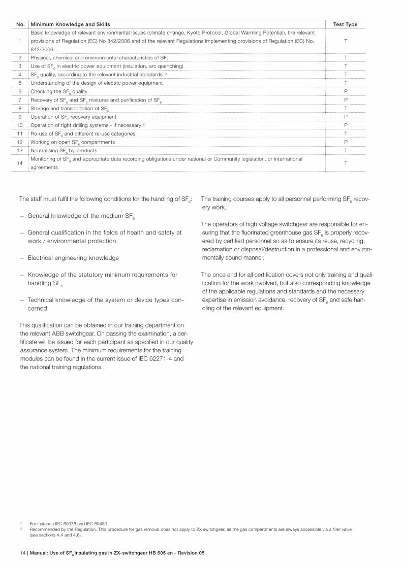
Minimum requirements as to the skills and knowledge to be covered by the evaluation bodies
The examination shall comprise the following:
a) a theoretical test with one or more questions testing that skill or
knowledge, as indicated in the column “Test Type” by (T);
b) a practical test where the applicant shall perform the corre-
sponding task with the relevant material, tools and equipment, as
indicated in the column “Test Type” by (P).
14 | Manual: Use of SF6 insulating gas in ZX-switchgear HB 605 en - Revision 05
No. Minimum Knowledge and Skills Test Type
1
Basic knowledge of relevant environmental issues (climate change, Kyoto Protocol, Global Warming Potential), the relevant
provisions of Regulation (EC) No 842/2006 and of the relevant Regulations implementing provisions of Regulation (EC) No.
842/2006.
T
2 Physical, chemical and environmental characteristics of SF6
T
3 Use of SF6 in electric power equipment (insulation, arc quenching) T
4 SF6 quality, according to the relevant industrial standards 1) T
5 Understanding of the design of electric power equipment T
6 Checking the SF6 quality P
7 Recovery of SF6 and SF
6 mixtures and purification of SF
6P
8 Storage and transportation of SF6
T
9 Operation of SF6 recovery equipment P
10 Operation of tight drilling systems - if necessary 2) P
11 Re-use of SF6 and different re-use categories T
12 Working on open SF6 compartments P
13 Neutralising SF6 by-products T
14Monitoring of SF
6 and appropriate data recording obligations under national or Community legislation, or international
agreementsT
The staff must fulfi l the following conditions for the handling of SF6:
− General knowledge of the medium SF6
− General qualification in the fields of health and safety at
work / environmental protection
− Electrical engineering knowledge
− Knowledge of the statutory minimum requirements for
handling SF6
− Technical knowledge of the system or device types con-
cerned
This qualifi cation can be obtained in our training department on
the relevant ABB switchgear. On passing the examination, a cer-
tifi cate will be issued for each participant as specifi ed in our quality
assurance system. The minimum requirements for the training
modules can be found in the current issue of IEC 62271-4 and
the national training regulations.
1) For instance IEC 60376 and IEC 604802) Recommended by the Regulation. This procedure for gas removal does not apply to ZX switchgear, as the gas compartments are always accessible via a fi ller valve
(see sections 4.4 and 4.6).
The training courses apply to all personnel performing SF6 recov-
ery work.
The operators of high voltage switchgear are responsible for en-
suring that the fl uorinated greenhouse gas SF6 is properly recov-
ered by certifi ed personnel so as to ensure its reuse, recycling,
reclamation or disposal/destruction in a professional and environ-
mentally sound manner.
The once and for all certifi cation covers not only training and quali-
fi cation for the work involved, but also corresponding knowledge
of the applicable regulations and standards and the necessary
expertise in emission avoidance, recovery of SF6 and safe han-
dling of the relevant equipment.

Manual: Use of SF6 insulating gas in ZX-switchgear HB 605 en - Revision 05 15
6
1 2 3 4 5
1
4.3 Delivery form of SF6 in gas
cylinders
If required in exceptional cases, SF6 is delivered in liquid form in
pressure vessels (gas cylinders). Only use SF6 which complies
with IEC 60376 or IEC 60480. Handle, store and use the gas ves-
sels in accordance with IEC 62271-4 and the local regulations.
A gas analysis is available for every gas delivery.
Store the pressurized gas vessels in a dry, clean place protected
from direct sunlight at a maximum temperature of 50 °C. If tem-
peratures of over 50 °C cannot be ruled out during storage or
transport, order gas vessels with a correspondingly reduced fi lling
factor.
As a rule, no deliveries of gas cylinders are required.
Fig. 4.4.1: Filler valve with protective cap
1 Filler valve
2 Valve pin
3 Protective cap
4.4 Notes on the filler valve
Figure 4.4.1 shows the fi ller valve with protective cap. The protec-
tive cap can be unscrewed by turning it counter-clockwise (fi gure
4.4.2).
Do not press the valve pin (2) in, as gas would flow
out of the valve.
A coupling is necessary to connect a hose to the fi ller valve (fi gure
4.4.3). The coupling has an M 20 x 1.5 thread. If the union nut on
the hose set has a different thread, use an appropriate adapter
(fi gure 4.4.4).
6 Adapter
Fig. 4.4.2: Filler valve, protective cap removed
3
2
Fig. 4.4.3: Filler valve with coupling for hose connection
1 Filler valve
2 Locking ring
3 Coupling
4 M 20 x 1.5 thread
5 Union nut on the hose set
Fig. 4.4.4: Using an adapter to fit the union nut on the hose set
16 | Manual: Use of SF6 insulating gas in ZX-switchgear HB 605 en - Revision 05
4.5 Topping up insulating gas
Erection of the switchgear
If the panels are to be transported by air freight (an exceptional
case), the gas compartments are delivered with a reduced SF6
pressure. In such cases, the pressure is to be increased to the
rated fi lling pressure prior to installation of the panels.
Switchgear in service
It is not necessary to top up the insulating gas during the expect-
ed service life of the system. Should a pressure loss signal never-
theless be issued, the following procedure is to be adopted:
− Record the time of the pressure loss signal.
− Clarify the cause of the pressure loss signal. A pressure
loss signal may also result from a defective electrical
connection in the secondary circuit or a defective density
sensor.
− Measure the pressure in the gas compartment concerned
with a temperature-compensated pressure gauge.
− Notify the ABB service department immediately and agree
the further action to be taken.
− Note: Temporary operation of the panels at atmospheric
pressure (> 100 kPa) is in principle possible if the SF6
content of the insulating gas is at least 95 %. (Exceptions:
double feeder panels with a rated voltage of 24 kV, panels
with a rated voltage of 40.5 kV, switching of the switch-
disconnector and panels with switch-disconnectors and
fuses. See section 6.1.)
Topping up the insulating gas
− Connect the hose of the gas filling unit to the coupling
(figure 4.4.3). Use an adapter if necessary to fit the thread
of the connecting hose to the M 20 x 1.5 thread of the
coupling (figure 4.4.4).
− Unscrew the protective cap from the filler valve (figure
4.4.2). A fastening cord prevents the cap from being lost.
Do not press the valve pin in, as gas would flow out
of the valve!
− Fit the coupling (figure 4.4.3) to the filler valve by pulling the
locking ring on the coupling back and pressing the cou-
pling onto the filler valve.
− Allow the insulating gas to flow into the gas compartment
as described in the operating instructions for the SF6 gas
filling unit used. The required filling pressure is equivalent to
the rated filling pressure for insulation.
− Monitor the pressure rise during the topping up process.
Perform the checks during temporary interruptions to the
gas feed.
− Remove the filler hose. In that process the locking ring is to
be pulled back and the coupling withdrawn from the filler
valve.
− Finally refit the protective cap to the filler valve.
4.6 Removal of insulating gas
Removal of insulating gas from the gas compartments in the
switchgear system is only necessary
− before repair work inside a gas compartment, and
− at the end of the service life of the switchgear.
SF6 must never be discharged into the atmosphere. The gas can
be removed, tested and stored using a gas recovery unit.
Procedure
− Connect the hose of the gas recovery unit to the coupling
(figure 4.4.3). Use an adapter if necessary to fit the thread
of the connecting hose to the M 20 x 1.5 thread of the
coupling (figure 4.4.4).
− Unscrew the protective cap from the filler valve (figure
4.4.2). A fastening cord prevents the cap from being lost.
Do not press the valve pin in, as gas would flow out
of the valve!
− Fit the coupling (figure 4.4.3) to the filler valve by pulling the
locking ring on the coupling back and pressing the cou-
pling onto the filler valve.
− Test the gas, remove and store it in accordance with the
operating instructions for the gas recovery unit.
− Remove the filler hose. In that process the locking ring is to
be pulled back and the coupling withdrawn from the filler
valve.
− Finally refit the protective cap to the filler valve.
Manual: Use of SF6 insulating gas in ZX-switchgear HB 605 en - Revision 05 17
4.7 Filling compartments with
insulating gas
Filling of individual gas compartments with insulating gas is only
necessary
− after fitting of heat sinks and/or to-mounted boxes for the
busbar metering system with isolating devbice at ZX2 and
− after repair work inside a gas compartment.
The air or the N2 transport gas is removed from the gas compart-
ment. The gas compartment concerned can be fi lled with SF6 at a
pressure of ≤ 1 kPa (= 10 mbar).
New drying agent must always be used in the gas compartments
when they are fi lled with insulating gas (see section 4.9).
Procedure
− Connect the hose of the vacuum pump to the coupling
(figure 4.4.3). Use an adapter if necessary to fit the thread
of the connecting hose to the M 20 x 1.5 thread of the
coupling (figure 4.4.4).
− Unscrew the protective cap from the filler valve (figure
4.4.2). A fastening cord prevents the cap from being lost.
− Fit the coupling (figure 4.4.3) to the filler valve by pulling the
locking ring on the coupling back and pressing the cou-
pling onto the filler valve.
− Evacuate the gas compartment to a pressure of ≤ 1 kPa
(= 10 mbar). Perform pressure measurements during the
evacuation process with the pump or hose valves tempo-
rarily closed. Leave the pump switched on for a further 30
minutes.
− Connect an SF6 gas filling unit to the filler valve in place of
the vacuum pump.
− Allow the SF6 to flow into the gas compartment as de-
scribed in the operating instructions for the SF6 gas filling
unit used. The required filling pressure is equivalent to the
rated filling pressure for insulation.
− Remove the filler hose. In that process the locking ring is to
be pulled back and the coupling withdrawn from the filler
valve.
− Refit the protective cap to the filler valve.
− Carefully check the tightness of the gas compartment and
the filler valves with a gas leakage tester. The scanning
speed should not exceed 1-2 cm / s.
4.8 Testing of insulating gas
We recommend you to conduct dew point measurement of the
insulating gas after gas work at site. The dew point measurement
can take place during operation of the panel concerned, and
should be performed a few weeks after fi lling it with gas. After that
period, a constant gas humidity has been established.
Testing of the insulating gas is not necessary during normal opera-
tion of the ZX switchgear.
Procedure for dew point measurement
Connect the fi ller valve of the gas compartment to a dew point
measuring instrument. Determine the dew point of the gas as de-
scribed in the operating instructions for the measuring instrument.
In connection with the operating conditions for indoor switchgear,
the dew point must not exceed a value of -5 °C 1). For safety
reasons, we recommend a minimum value for the dew point of
-15 °C 1).
4.9 Handling of the drying agent
Replacement of drying agent bags is not necessary while the
switchgear is in service.
Replace the existing drying agent bags after work in opened gas
compartments. Consult the tables in section 6.3 for the number of
drying agent bags.
Replace the drying agent bags immediately before sealing the gas
compartment. Fill the gas compartment with SF6 immediately after
sealing.
Notes:
− The drying agent bags are heat-sealed in film to protect
them from moisture. An indicator inserted in the protective
bag shows the moisture content, as follows:
− When the indicator is blue in colour, the drying agent
bags are dry and usable.
− When the indicator is pink in colour, the drying agent
bags are moist and not usable.
1) For a ZX0 switchgear installation without auxiliary voltage at an ambient temperature of -25 °C, a correspondingly lower value is required. In this case we recommend a
minimum dew point of -35 °C.
18 | Manual: Use of SF6 insulating gas in ZX-switchgear HB 605 en - Revision 05
− Only open the protective bags immediately before the dry-
ing agent bags are to be placed in the gas compartment.
− Drying agent bags which have not been contaminated
with SF6 decomposition products can be disposed of as
residual waste.
− Follow the regulations of the responsible local authorities
when disposing of drying agent bags which are contami-
nated with SF6 decomposition products.
5 Actions at the end of the switchgear
service life
SF6 must never be discharged into the atmosphere.
ABB can be appointed to decommission and dismantle the
switchgear. The switchgear system is then professionally disman-
tled by ABB and the SF6, which is normally reusable, removed
before the switchgear is broken down into its remaining com-
ponents. In ZX systems, the SF6 can be removed at site after
decommissioning with appropriate equipment connected to the
fi ller valves. If it complies with IEC 60480 (DIN EN 60480) standard
after removal, it can be directly reused by the operator. If it is in
accordance with the gas manufacturer’s “Re-use Specifi cation”
according to IEC 62271-4, it can be returned to ABB or the gas
manufacturer as a product.
Drying agent bags which have not been contaminated with SF6
decomposition products can be disposed of as residual waste.
Follow the regulations of the responsible local authorities when
disposing of drying agent bags which are contaminated with SF6
decomposition products.
Manual: Use of SF6 insulating gas in ZX-switchgear HB 605 en - Revision 05 19
6 Technical data
6.1 Ratings
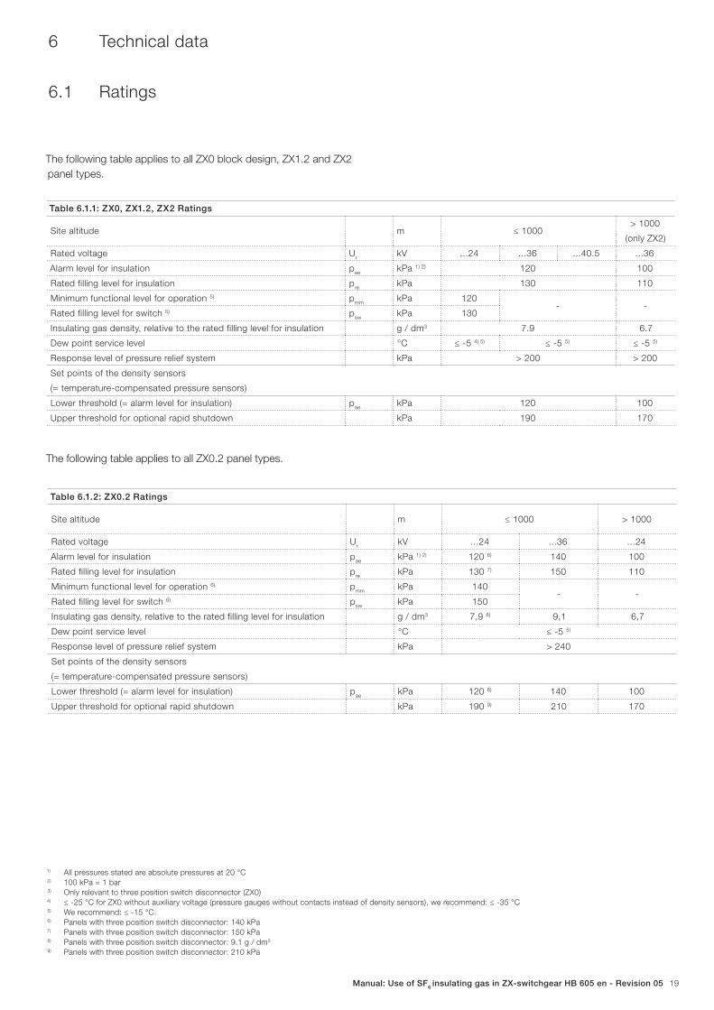
1) All pressures stated are absolute pressures at 20 °C2) 100 kPa = 1 bar3) Only relevant to three position switch disconnector (ZX0)4) ≤ -25 °C for ZX0 without auxiliary voltage (pressure gauges without contacts instead of density sensors), we recommend: ≤ -35 °C5) We recommend: ≤ -15 °C.6) Panels with three position switch disconnector: 140 kPa7) Panels with three position switch disconnector: 150 kPa8) Panels with three position switch disconnector: 9.1 g / dm3
9) Panels with three position switch disconnector: 210 kPa
The following table applies to all ZX0 block design, ZX1.2 and ZX2
panel types.
Table 6.1.1: ZX0, ZX1.2, ZX2 Ratings
Site altitude m ≤ 1000> 1000
(only ZX2)
Rated voltage Ur
kV ...24 ...36 ...40.5 ...36
Alarm level for insulation pae
kPa 1) 2) 120 100
Rated filling level for insulation pre
kPa 130 110
Minimum functional level for operation 5) pmm
kPa 120- -
Rated filling level for switch 5) psw
kPa 130
Insulating gas density, relative to the rated filling level for insulation g / dm3 7.9 6.7
Dew point service level °C ≤ -5 4) 5) ≤ -5 5) ≤ -5 5)
Response level of pressure relief system kPa > 200 > 200
Set points of the density sensors
(= temperature-compensated pressure sensors)
Lower threshold (= alarm level for insulation) pae
kPa 120 100
Upper threshold for optional rapid shutdown kPa 190 170
Table 6.1.2: ZX0.2 Ratings
Site altitude m ≤ 1000 > 1000
Rated voltage Ur
kV ...24 ...36 ...24
Alarm level for insulation pae
kPa 1) 2) 120 6) 140 100
Rated filling level for insulation pre
kPa 130 7) 150 110
Minimum functional level for operation 6) pmm
kPa 140- -
Rated filling level for switch 6) psw
kPa 150
Insulating gas density, relative to the rated filling level for insulation g / dm3 7,9 8) 9,1 6,7
Dew point service level °C ≤ -5 5)
Response level of pressure relief system kPa > 240
Set points of the density sensors
(= temperature-compensated pressure sensors)
Lower threshold (= alarm level for insulation) pae
kPa 120 6) 140 100
Upper threshold for optional rapid shutdown kPa 190 9) 210 170
The following table applies to all ZX0.2 panel types.
20 | Manual: Use of SF6 insulating gas in ZX-switchgear HB 605 en - Revision 05
6.2 Insulating gas capacities
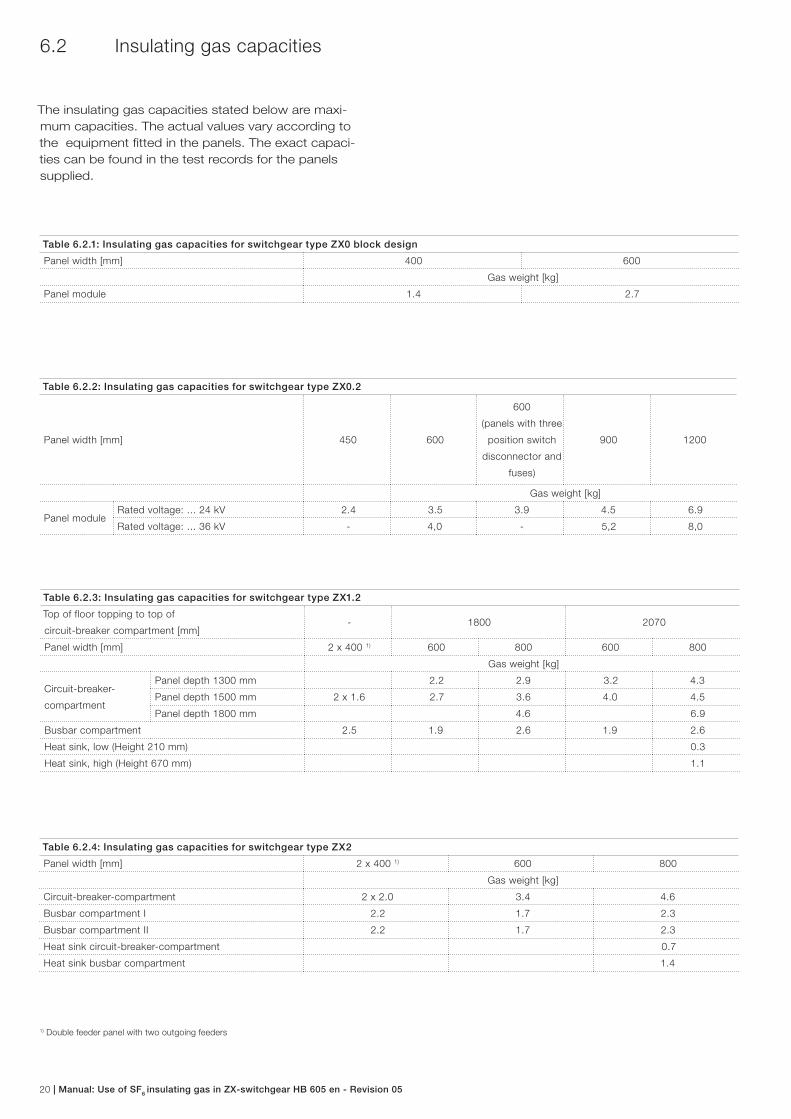
Table 6.2.3: Insulating gas capacities for switchgear type ZX1.2
Top of floor topping to top of
circuit-breaker compartment [mm]- 1800 2070
Panel width [mm] 2 x 400 1) 600 800 600 800
Gas weight [kg]
Circuit-breaker-
compartment
Panel depth 1300 mm 2.2 2.9 3.2 4.3
Panel depth 1500 mm 2 x 1.6 2.7 3.6 4.0 4.5
Panel depth 1800 mm 4.6 6.9
Busbar compartment 2.5 1.9 2.6 1.9 2.6
Heat sink, low (Height 210 mm) 0.3
Heat sink, high (Height 670 mm) 1.1
Table 6.2.4: Insulating gas capacities for switchgear type ZX2
Panel width [mm] 2 x 400 1) 600 800
Gas weight [kg]
Circuit-breaker-compartment 2 x 2.0 3.4 4.6
Busbar compartment I 2.2 1.7 2.3
Busbar compartment II 2.2 1.7 2.3
Heat sink circuit-breaker-compartment 0.7
Heat sink busbar compartment 1.4
Table 6.2.1: Insulating gas capacities for switchgear type ZX0 block design
Panel width [mm] 400 600
Gas weight [kg]
Panel module 1.4 2.7
1) Double feeder panel with two outgoing feeders
Table 6.2.2: Insulating gas capacities for switchgear type ZX0.2
Panel width [mm] 450 600
600
(panels with three
position switch
disconnector and
fuses)
900 1200
Gas weight [kg]
Panel moduleRated voltage: ... 24 kV 2.4 3.5 3.9 4.5 6.9
Rated voltage: ... 36 kV - 4,0 - 5,2 8,0
The insulating gas capacities stated below are maxi-
mum capacities. The actual values vary according to
the equipment fi tted in the panels. The exact capaci-
ties can be found in the test records for the panels
supplied.
Manual: Use of SF6 insulating gas in ZX-switchgear HB 605 en - Revision 05 21
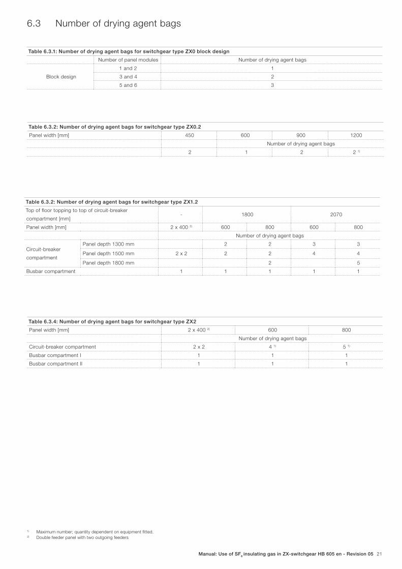
Table 6.3.2: Number of drying agent bags for switchgear type ZX1.2
Top of floor topping to top of circuit-breaker
compartment [mm]- 1800 2070
Panel width [mm] 2 x 400 2) 600 800 600 800
Number of drying agent bags
Circuit-breaker
compartment
Panel depth 1300 mm 2 2 3 3
Panel depth 1500 mm 2 x 2 2 2 4 4
Panel depth 1800 mm 2 5
Busbar compartment 1 1 1 1 1
Table 6.3.4: Number of drying agent bags for switchgear type ZX2
Panel width [mm] 2 x 400 2) 600 800
Number of drying agent bags
Circuit-breaker compartment 2 x 2 4 1) 5 1)
Busbar compartment I 1 1 1
Busbar compartment II 1 1 1
Table 6.3.1: Number of drying agent bags for switchgear type ZX0 block design
Number of panel modules Number of drying agent bags
Block design
1 and 2 1
3 and 4 2
5 and 6 3
6.3 Number of drying agent bags
1) Maximum number; quantity dependent on equipment fi tted. 2) Double feeder panel with two outgoing feeders
Table 6.3.2: Number of drying agent bags for switchgear type ZX0.2
Panel width [mm] 450 600 900 1200
Number of drying agent bags
2 1 2 2 1)
22 | Manual: Use of SF6 insulating gas in ZX-switchgear HB 605 en - Revision 05
7 Sample works instructions
The sample works instructions shown are intended to serve as examples for the compilation of instructions in your company. Adjust-
ments to national technical standards and the accident prevention regulations of the country in which the switchgear is operated might
be necessary.
Manual: Use of SF6 insulating gas in ZX-switchgear HB 605 en - Revision 05 23
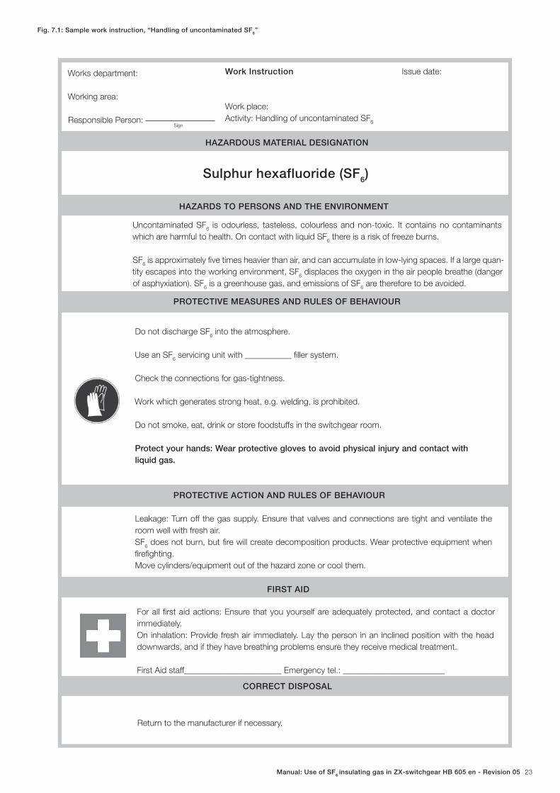
Fig. 7.1: Sample work instruction, “Handling of uncontaminated SF6”
Works department:
Working area:
Responsible Person:
Work Instruction
Work place:
Activity: Handling of uncontaminated SF6
Issue date:
HAZARDOUS MATERIAL DESIGNATION
Sulphur hexafluoride (SF6)
HAZARDS TO PERSONS AND THE ENVIRONMENT
Uncontaminated SF6 is odourless, tasteless, colourless and non-toxic. It contains no contaminants
which are harmful to health. On contact with liquid SF6 there is a risk of freeze burns.
SF6 is approximately fi ve times heavier than air, and can accumulate in low-lying spaces. If a large quan-
tity escapes into the working environment, SF6 displaces the oxygen in the air people breathe (danger
of asphyxiation). SF6 is a greenhouse gas, and emissions of SF
6 are therefore to be avoided.
PROTECTIVE MEASURES AND RULES OF BEHAVIOUR
Do not discharge SF6 into the atmosphere.
Use an SF6 servicing unit with ___________ fi ller system.
Check the connections for gas-tightness.
Work which generates strong heat, e.g. welding, is prohibited.
Do not smoke, eat, drink or store foodstuffs in the switchgear room.
Protect your hands: Wear protective gloves to avoid physical injury and contact with liquid gas.
PROTECTIVE ACTION AND RULES OF BEHAVIOUR
Leakage: Turn off the gas supply. Ensure that valves and connections are tight and ventilate the
room well with fresh air.
SF6 does not burn, but fi re will create decomposition products. Wear protective equipment when
fi refi ghting.
Move cylinders/equipment out of the hazard zone or cool them.
FIRST AID
For all fi rst aid actions: Ensure that you yourself are adequately protected, and contact a doctor
immediately.
On inhalation: Provide fresh air immediately. Lay the person in an inclined position with the head
downwards, and if they have breathing problems ensure they receive medical treatment.
First Aid staff_______________________ Emergency tel.: ________________________
CORRECT DISPOSAL
Return to the manufacturer if necessary.
Sign
24 | Manual: Use of SF6 insulating gas in ZX-switchgear HB 605 en - Revision 05
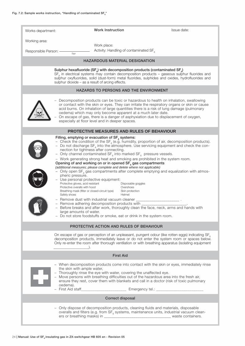
Fig. 7.2: Sample works instruction, “Handling of contaminated SF6”
HAZARDOUS MATERIAL DESIGNATION
Sulphur hexafl uoride (SF6) with decomposition products (contaminated SF6)SF
6 in electrical systems may contain decomposition products – gaseous sulphur fl uorides and
sulphur oxyfl uorides, solid (dust-form) metal fl uorides, sulphides and oxides, hydrofl uorides and sulphur dioxide – as a result of arcing effects.
HAZARDS TO PERSONS AND THE ENVIRONMENT
− Decomposition products can be toxic or hazardous to health on inhalation, swallowing or contact with the skin or eyes. They can irritate the respiratory organs or skin or cause acid burns. On inhalation of large quantities there is a risk of lung damage (pulmonary oedema) which may only become apparent at a much later date.
− On escape of gas, there is a danger of asphyxiation due to displacement of oxygen, especially at floor level and in deeper spaces.
PROTECTIVE MEASURES AND RULES OF BEHAVIOURFilling, emptying or evacuation of SF6 systems:
− Check the condition of the SF6 (e.g. humidity, proportion of air, decomposition products).
− Do not discharge SF6 into the atmosphere. Use servicing equipment and check the con-
nection for tightness after connecting. − Only channel contaminated SF
6 into marked SF
6 pressure vessels.
− Work generating strong heat and smoking are prohibited in the system room. Opening of and working on or in opened SF6 gas compartments (additional measures; please complete and delete where not applicable)
− Only open SF6 gas compartments after complete emptying and equalization with atmos-
pheric pressure. − Use personal protective equipment:
Protective gloves, acid resistant Disposable goggles
Protective overalls with hood Overshoes
Breathing mask (fi lter or closed-circuit type) Skin protection
Safety shoes Helmet
− Remove dust with industrial vacuum cleaner ______________________ . − Remove adhering decomposition products with _______________________. − Before breaks and after work, thoroughly clean the face, neck, arms and hands with
large amounts of water. − Do not store foodstuffs or smoke, eat or drink in the system room.
PROTECTIVE ACTION AND RULES OF BEHAVIOUR
On escape of gas or perception of an unpleasant, pungent odour (like rotten eggs) indicating SF6
decomposition products, immediately leave or do not enter the system room or spaces below. Only re-enter the room after thorough ventilation or with breathing apparatus (isolating equipment ___________________).
First Aid
− When decomposition products come into contact with the skin or eyes, immediately rinse the skin with ample water,
− Thoroughly rinse the eye with water, covering the unaffected eye. − Move persons with breathing difficulties out of the hazardous area into the fresh air,
ensure they rest, cover them with blankets and call in a doctor (risk of toxic pulmonary oedema).
− First Aid staff_______________________ Emergency tel.: ________________________
Correct disposal
− Only dispose of decomposition products, cleaning fluids and materials, disposable overalls and filters (e.g. from SF
6 systems, maintenance units, industrial vacuum clean-
ers or breathing masks) in __________________________________ waste containers.
Works department:
Working area:
Responsible Person:
Work Instruction
Work place:
Activity: Handling of contaminated SF6
Issue date:
Sign
Manual: Use of SF6 insulating gas in ZX-switchgear HB 605 en - Revision 05 25
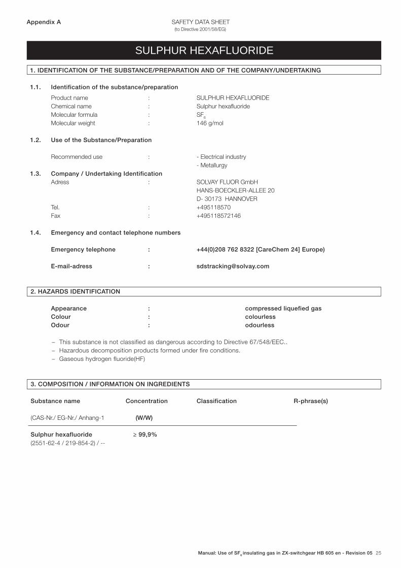
SAFETY DATA SHEET(to Directive 2001/58/EG)
1. IDENTIFICATION OF THE SUBSTANCE/PREPARATION AND OF THE COMPANY/UNDERTAKING
1.1. Identification of the substance/preparation
Product name : SULPHUR HEXAFLUORIDE
Chemical name : Sulphur hexafl uoride
Molecular formula : SF6
Molecular weight : 146 g/mol
1.2. Use of the Substance/Preparation
Recommended use : - Electrical industry
- Metallurgy
1.3. Company / Undertaking Identification Adress : SOLVAY FLUOR GmbH
HANS-BOECKLER-ALLEE 20
D- 30173 HANNOVER
Tel. : +495118570
Fax : +495118572146
1.4. Emergency and contact telephone numbers
Emergency telephone : +44(0)208 762 8322 [CareChem 24] Europe)
E-mail-adress : [email protected]
2. HAZARDS IDENTIFICATION
Appearance : compressed liquefied gas Colour : colourless Odour : odourless
− This substance is not classified as dangerous according to Directive 67/548/EEC..
− Hazardous decomposition products formed under fire conditions.
− Gaseous hydrogen fluoride(HF)
3. COMPOSITION / INFORMATION ON INGREDIENTS
Substance name Concentration Classification R-phrase(s)
(CAS-Nr./ EG-Nr./ Anhang-1 (W/W)
Sulphur hexafluoride ≥ 99,9%(2551-62-4 / 219-854-2) / --
SULPHUR HEXAFLUORIDE
Appendix A
26 | Manual: Use of SF6 insulating gas in ZX-switchgear HB 605 en - Revision 05
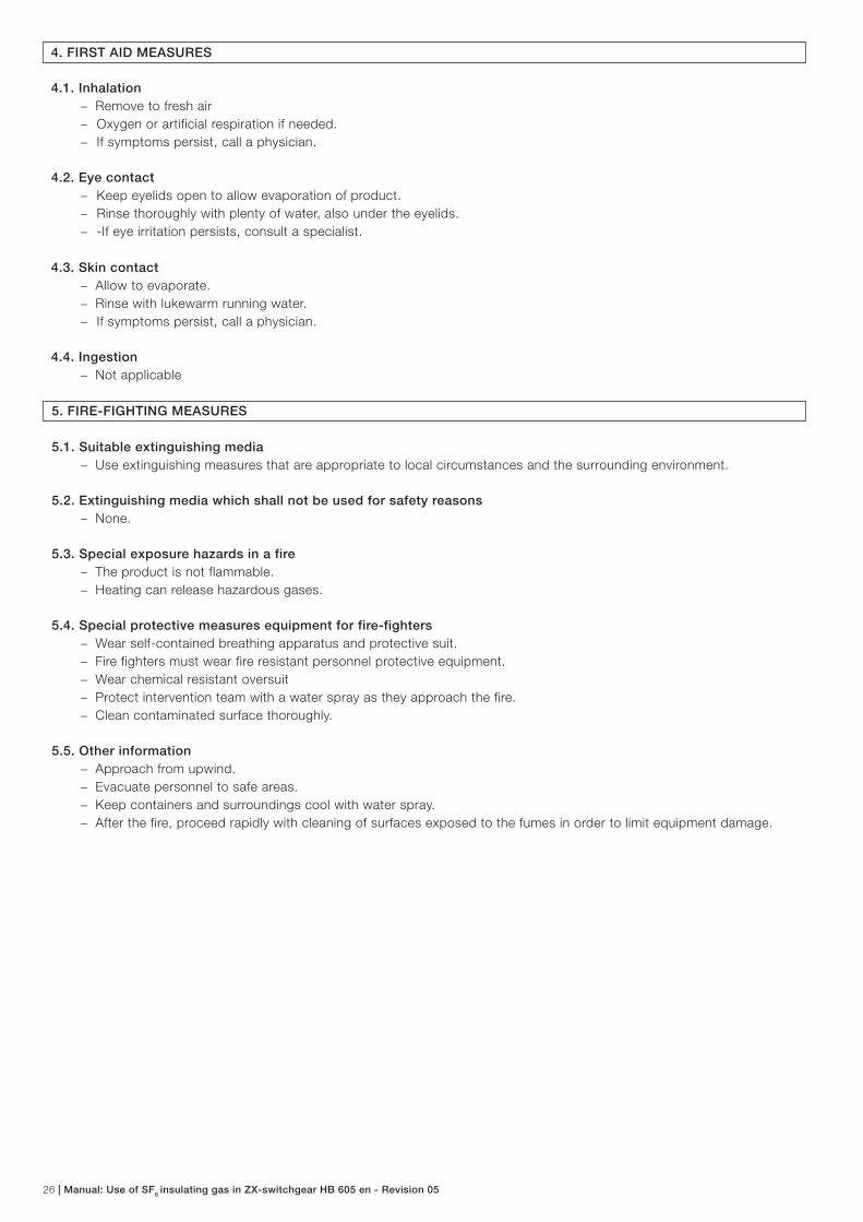
4. FIRST AID MEASURES
4.1. Inhalation − Remove to fresh air
− Oxygen or artificial respiration if needed.
− If symptoms persist, call a physician.
4.2. Eye contact − Keep eyelids open to allow evaporation of product.
− Rinse thoroughly with plenty of water, also under the eyelids.
− -If eye irritation persists, consult a specialist.
4.3. Skin contact − Allow to evaporate.
− Rinse with lukewarm running water.
− If symptoms persist, call a physician.
4.4. Ingestion − Not applicable
5. FIRE-FIGHTING MEASURES
5.1. Suitable extinguishing media − Use extinguishing measures that are appropriate to local circumstances and the surrounding environment.
5.2. Extinguishing media which shall not be used for safety reasons − None.
5.3. Special exposure hazards in a fire − The product is not flammable.
− Heating can release hazardous gases.
5.4. Special protective measures equipment for fire-fighters − Wear self-contained breathing apparatus and protective suit.
− Fire fighters must wear fire resistant personnel protective equipment.
− Wear chemical resistant oversuit
− Protect intervention team with a water spray as they approach the fire.
− Clean contaminated surface thoroughly.
5.5. Other information − Approach from upwind.
− Evacuate personnel to safe areas.
− Keep containers and surroundings cool with water spray.
− After the fire, proceed rapidly with cleaning of surfaces exposed to the fumes in order to limit equipment damage.
Manual: Use of SF6 insulating gas in ZX-switchgear HB 605 en - Revision 05 27
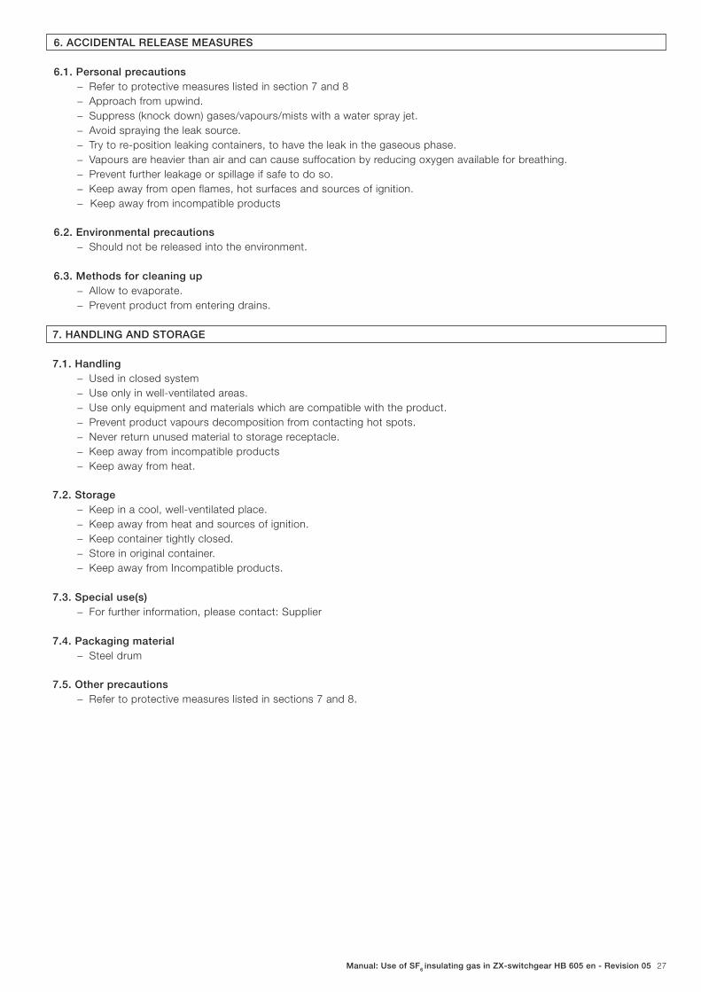
6. ACCIDENTAL RELEASE MEASURES
6.1. Personal precautions − Refer to protective measures listed in section 7 and 8
− Approach from upwind.
− Suppress (knock down) gases/vapours/mists with a water spray jet.
− Avoid spraying the leak source.
− Try to re-position leaking containers, to have the leak in the gaseous phase.
− Vapours are heavier than air and can cause suffocation by reducing oxygen available for breathing.
− Prevent further leakage or spillage if safe to do so.
− Keep away from open flames, hot surfaces and sources of ignition.
− Keep away from incompatible products
6.2. Environmental precautions − Should not be released into the environment.
6.3. Methods for cleaning up − Allow to evaporate.
− Prevent product from entering drains.
7. HANDLING AND STORAGE
7.1. Handling − Used in closed system
− Use only in well-ventilated areas.
− Use only equipment and materials which are compatible with the product.
− Prevent product vapours decomposition from contacting hot spots.
− Never return unused material to storage receptacle.
− Keep away from incompatible products
− Keep away from heat.
7.2. Storage − Keep in a cool, well-ventilated place.
− Keep away from heat and sources of ignition.
− Keep container tightly closed.
− Store in original container.
− Keep away from Incompatible products.
7.3. Special use(s) − For further information, please contact: Supplier
7.4. Packaging material − Steel drum
7.5. Other precautions − Refer to protective measures listed in sections 7 and 8.
28 | Manual: Use of SF6 insulating gas in ZX-switchgear HB 605 en - Revision 05
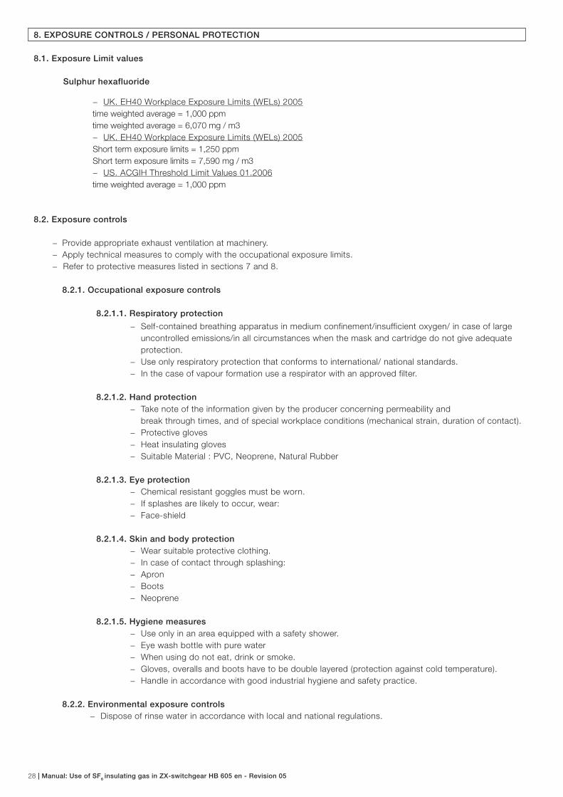
8. EXPOSURE CONTROLS / PERSONAL PROTECTION
8.1. Exposure Limit values
Sulphur hexafluoride
− UK. EH40 Workplace Exposure Limits (WELs) 2005
time weighted average = 1,000 ppm
time weighted average = 6,070 mg / m3
− UK. EH40 Workplace Exposure Limits (WELs) 2005
Short term exposure limits = 1,250 ppm
Short term exposure limits = 7,590 mg / m3
− US. ACGIH Threshold Limit Values 01.2006
time weighted average = 1,000 ppm
8.2. Exposure controls
− Provide appropriate exhaust ventilation at machinery.
− Apply technical measures to comply with the occupational exposure limits.
− Refer to protective measures listed in sections 7 and 8.
8.2.1. Occupational exposure controls
8.2.1.1. Respiratory protection
− Self-contained breathing apparatus in medium confinement/insufficient oxygen/ in case of large
uncontrolled emissions/in all circumstances when the mask and cartridge do not give adequate
protection.
− Use only respiratory protection that conforms to international/ national standards.
− In the case of vapour formation use a respirator with an approved filter.
8.2.1.2. Hand protection − Take note of the information given by the producer concerning permeability and
break through times, and of special workplace conditions (mechanical strain, duration of contact).
− Protective gloves
− Heat insulating gloves
− Suitable Material : PVC, Neoprene, Natural Rubber
8.2.1.3. Eye protection − Chemical resistant goggles must be worn.
− If splashes are likely to occur, wear:
− Face-shield
8.2.1.4. Skin and body protection − Wear suitable protective clothing.
− In case of contact through splashing:
− Apron
− Boots
− Neoprene
8.2.1.5. Hygiene measures − Use only in an area equipped with a safety shower.
− Eye wash bottle with pure water
− When using do not eat, drink or smoke.
− Gloves, overalls and boots have to be double layered (protection against cold temperature).
− Handle in accordance with good industrial hygiene and safety practice.
8.2.2. Environmental exposure controls − Dispose of rinse water in accordance with local and national regulations.
Manual: Use of SF6 insulating gas in ZX-switchgear HB 605 en - Revision 05 29
9. PHYSICAL AND CHEMICAL PROPERTIES
9.1. General information (appearance, odour)Form : Compressed liquefi ed gas
Colour : colourless
Odour : odourless
9.2. Important health, safety and environment information pH : Remarks: neutral
Boiling point/boiling range : -63,8 °C
Remarks: Sublimation point
Flash point: : Remarks: does not fl ash
Flammability : Remarks: This product is not fl ammable.
Explosive properties : Explosion danger:
Remarks: See section 10
Oxidizing properties : Remarks: Non oxidizer
Vapour pressure : 21.4 bar
Temperature: 20 °C
: 37.1 bar
Temperature: 45 °C
Relative Density / Density : 1.56
Solubility : Water
0.04 g / l
Remarks: slightly soluble
Temperature: 20 °C
: Alcohol
: Ether
Partition coeffi cient log P o/w
n-octanol/water : 1.68
Vapour density (air = 1) : 5.1
9.3. Other data
Freezing point : -50.8 °C
Decomposition temperature 200 °C
Remarks: Decomposition under infl uence of moisture is highly accelerated by
heating.
800 °C
Remarks: Dry air
10. STABILITY AND REACTIVITY
10.1. Stability − Stable under recommended storage conditions.
− Vapours are heavier than air and may spread along floors.
− Hazardous Polymerisation/Polymerization: no
10.2. Conditions to avoid
− Heat
10.3. Materials to avoid − Oxidizing agents
10.4. Hazardous decomposition products − Gaseous hydrogen fluoride (HF)., Sulphur dioxide, Sulphur compounds
30 | Manual: Use of SF6 insulating gas in ZX-switchgear HB 605 en - Revision 05
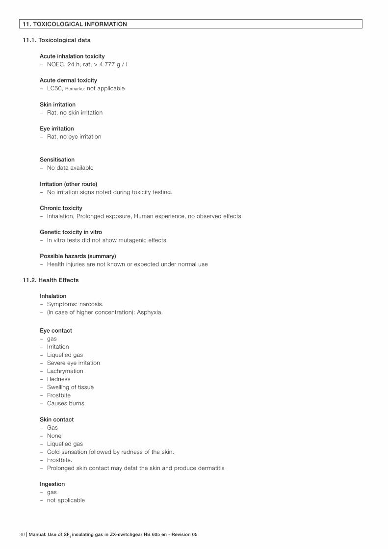
11. TOXICOLOGICAL INFORMATION
11.1. Toxicological data
Acute inhalation toxicity − NOEC, 24 h, rat, > 4.777 g / l
Acute dermal toxicity − LC50, Remarks: not applicable
Skin irritation − Rat, no skin irritation
Eye irritation − Rat, no eye irritation
Sensitisation − No data available
Irritation (other route) − No irritation signs noted during toxicity testing.
Chronic toxicity − Inhalation, Prolonged exposure, Human experience, no observed effects
Genetic toxicity in vitro − In vitro tests did not show mutagenic effects
Possible hazards (summary) − Health injuries are not known or expected under normal use
11.2. Health Effects
Inhalation − Symptoms: narcosis.
− (in case of higher concentration): Asphyxia.
Eye contact − gas
− Irritation
− Liquefied gas
− Severe eye irritation
− Lachrymation
− Redness
− Swelling of tissue
− Frostbite
− Causes burns
Skin contact − Gas
− None
− Liquefied gas
− Cold sensation followed by redness of the skin.
− Frostbite.
− Prolonged skin contact may defat the skin and produce dermatitis
Ingestion − gas
− not applicable

Manual: Use of SF6 insulating gas in ZX-switchgear HB 605 en - Revision 05 31
12. ECOLOGICAL INFORMATION
12.1. Ecotoxicity
Acute toxicity − Remarks: no data available
12.2. Mobility − Air, Henry’s law constant (H) = 452 kPa . m3 / mol
Conditions: calculated value
Remarks: considerable volatility
− Soil/sediments
Remarks: Non-signifi cant adsorption.
− Water, Evaporates, t 1/2
= 3.5 h
Conditions: calculated value
12.3. Persistence and degradability
Abiotic degradation − Air, t
1/2 > 1000 years
Result: not signifi cant photolysis
− Water/soil, t 1/2
> 1000 years
Result: Non signifi cant hydrolysis
Biodegradation − Remarks: The methods for determining biodegradability are not applicable to inorganic substances.
12.4. Bioaccumulative potential − Bioconcentration: Bioconcentration factor (BCF) = 89
Remarks: Calculated value
12.5. Other adverse effects − Global Warming Potential
= 23,900
Remarks: GWP (ITH 100 y), Source IPCC (International Panel on Climate Change)
12.6. Possible hazards (summary) − This product has no known eco-toxicological effects.
− Product is persistent in air.
− Other dangerous properties can not be excluded.
13. DISPOSAL CONSIDERATIONS
13.1. Waste from residues / unused products − In accordance with local and national regulations.
− Refer to manufacturer/supplier for information on recovery/recycling.
13.2. Packaging treatment − To avoid treatments, as far as possible, use dedicated containers.

32 | Manual: Use of SF6 insulating gas in ZX-switchgear HB 605 en - Revision 05
14. TRANSPORT INFORMATION
UN-Number 1080
IATA-DGR Class 2,2
ICAO-Labels NON-FLAMMABLE COMPRESSED GAS
Proper shipping name: SULPHUR HEXAFLUORIDE
IMDG
Class 2,2
IMDG-labels NON-FLAMMABLE COMPRESSED GAS
HI/UN-No. 1080
EmS: F-C,S-V
Proper shipping name: SULPHUR HEXAFLUORIDE
ADR Class 2
ADR/RID-Labels 2,2
HI/UN-Nr. 20/1080
Proper shipping name: SULPHUR HEXAFLUORIDE
15. REGULATORY INFORMATION
15.1. EG-Label − This substance is not classified as dangerous according to Directive 67/548/EEC.
15.2 Inventory Informations
Australian Inventory of Chemical Sustances : - In compliance with inventory
Canadian Domestic SubstancesList (DSL) : - In compliance with inventory
Inventory of Existing Chemical Substances (China)(IECS) : - In compliance with inventory
Japan (ENCS) List (ENCS((JP)) : - In compliance with inventory
New Zealand Single ComponentSub. List (NZ CLSC) : - In compliance with inventory
Toxic Substance Control Act -Liste (TSCA) : - In compliance with inventory
Liste der EU-Altstoffe (EINECS) : - In compliance with inventory
Korea Existing Chemicals Inv. (KECI) (KECI(KR)) : - In compliance with inventory
Philippines PICCS (PICCS (PH)) : - In compliance with inventory
15.3. Other regulations − European Waste Catalogue, Decision (2000/532/EC), Hazardous waste, Waste codes should be assigned by the user
based on the application for which the product was used.
Manual: Use of SF6 insulating gas in ZX-switchgear HB 605 en - Revision 05 33
16. OTHER DETAILS
16.1. Administrative information
− General revision
− Distribute new edition to clients
This SDS is only intended for the indicated country to which it is applicable. The European SDS format compliant with the applicable
European legislation is not intended for use nor distribution in countries outside the European Union with the exception of Norway and
Switzerland. Safety data sheets applicable in other countries/regions are available upon request. The information given corresponds
to the current state of our knowledge and experience of the product, and is not exhaustive. This applies to product which conforms
to the specifi cation, unless otherwise stated. In this case of combinations and mixtures one must make sure that no new dangers can
arise. In any case, the user is not exempt from observing all legal, administrative and regulatory procedures relating to the product,
personal hygiene, and protection of human welfare and the environment.


For your notes…

Contact usContact us
Note: We reserve the right to make technical changes or modify the contents of this document without prior noti-ce. With regard to purchase orders, the agreed particulars shall prevail. ABB AG does not accept any responsibility whatsoever for potential errors or possible lack of information in this document.
We reserve all rights in this document and in the subject matter
and illustrations contained therein. Any reproduction, disclosure to
third parties or utilization of its contents - in whole or in parts - is
forbidden without prior written consent of ABB AG.
Copyright© 2010 ABB
All rights reserved
© C
op
yrig
ht
AB
B.
1V
BA
68
0 6
05
P0
10
2 (0
2.2
01
5-
AB
B)
Your sales contact: www.abb.com/contacts
More product information: www.abb.com/productguide


![SAN]OSE CITYOF MemorandumFeeder from Switchgear M5 to Switchgear S16B 6. Feeder from Switchgear M5 to Switchgear ESB Engineer'sEstimate $384,787 $77,720 $211,326 $747,139 ... Ifthisproject](https://img.dokumen.tips/doc/110x75/5e7fcbe33356ee7623111eaf/sanose-cityof-feeder-from-switchgear-m5-to-switchgear-s16b-6-feeder-from-switchgear.jpg)