Embed Size (px)
Citation preview
1
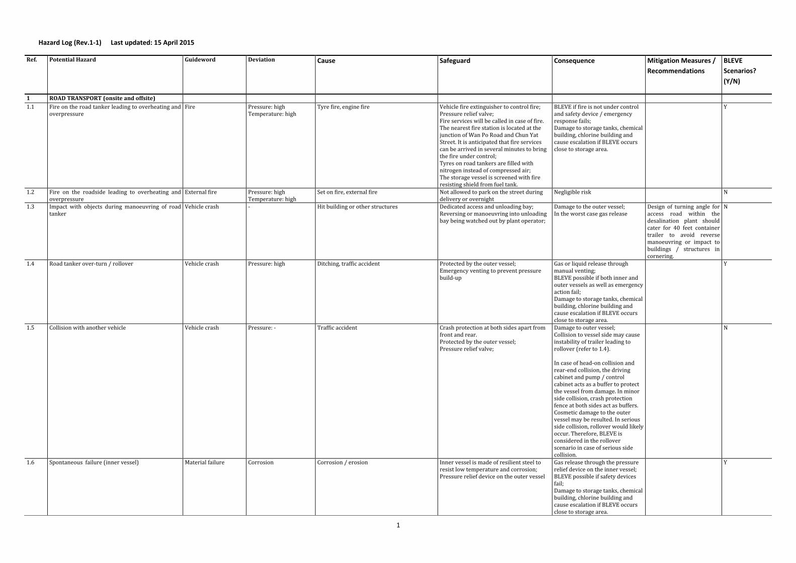
Hazard Log (Rev.1-1) Last updated: 15 April 2015
Ref. Potential Hazard Guideword Deviation Cause Safeguard Consequence Mitigation Measures /
Recommendations
BLEVE
Scenarios?
(Y/N)
1 ROAD TRANSPORT (onsite and offsite)
1.1 Fire on the road tanker leading to overheating and overpressure
Fire Pressure: high Temperature: high
Tyre fire, engine fire Vehicle fire extinguisher to control fire; Pressure relief valve; Fire services will be called in case of fire. The nearest fire station is located at the junction of Wan Po Road and Chun Yat Street. It is anticipated that fire services can be arrived in several minutes to bring the fire under control; Tyres on road tankers are filled with nitrogen instead of compressed air; The storage vessel is screened with fire resisting shield from fuel tank.
BLEVE if fire is not under control and safety device / emergency response fails; Damage to storage tanks, chemical building, chlorine building and cause escalation if BLEVE occurs close to storage area.
Y
1.2 Fire on the roadside leading to overheating and overpressure
External fire Pressure: high Temperature: high
Set on fire, external fire Not allowed to park on the street during delivery or overnight
Negligible risk N
1.3 Impact with objects during manoeuvring of road tanker
Vehicle crash - Hit building or other structures Dedicated access and unloading bay; Reversing or manoeuvring into unloading bay being watched out by plant operator;
Damage to the outer vessel; In the worst case gas release
Design of turning angle for access road within the desalination plant should cater for 40 feet container trailer to avoid reverse manoeuvring or impact to buildings / structures in cornering.
N
1.4 Road tanker over-turn / rollover Vehicle crash Pressure: high Ditching, traffic accident Protected by the outer vessel; Emergency venting to prevent pressure build-up
Gas or liquid release through manual venting; BLEVE possible if both inner and outer vessels as well as emergency action fail; Damage to storage tanks, chemical building, chlorine building and cause escalation if BLEVE occurs close to storage area.
Y
1.5 Collision with another vehicle Vehicle crash Pressure: - Traffic accident Crash protection at both sides apart from front and rear. Protected by the outer vessel; Pressure relief valve;
Damage to outer vessel; Collision to vessel side may cause instability of trailer leading to rollover (refer to 1.4). In case of head-on collision and rear-end collision, the driving cabinet and pump / control cabinet acts as a buffer to protect the vessel from damage. In minor side collision, crash protection fence at both sides act as buffers. Cosmetic damage to the outer vessel may be resulted. In serious side collision, rollover would likely occur. Therefore, BLEVE is considered in the rollover scenario in case of serious side collision.
N
1.6 Spontaneous failure (inner vessel) Material failure Corrosion Corrosion / erosion Inner vessel is made of resilient steel to resist low temperature and corrosion; Pressure relief device on the outer vessel
Gas release through the pressure relief device on the inner vessel; BLEVE possible if safety devices fail; Damage to storage tanks, chemical building, chlorine building and cause escalation if BLEVE occurs close to storage area.
Y

2
Ref. Potential Hazard Guideword Deviation Cause Safeguard Consequence Mitigation Measures /
Recommendations
BLEVE
Scenarios?
(Y/N)
1.7 Spontaneous failure (outer vessel) Material failure Corrosion Corrosion / erosion Pressure relief device on the inner vessel Loss vacuum insulation; heating up CO2 content; may trigger safety device on inner vessel leading to gas release; BLEVE if safety devices fail; Damage to storage tanks, chemical building, chlorine building and cause escalation if BLEVE occurs close to storage area.
Y
1.8 Road tanker is overfilled in the gas supplier’s plant and allowed leaving for the desalination plant
Human error Level: high Fail to open Trycock valve during refilling; Readings on gauges or instruments are ignored
Trycock, pressure gauge & content gauge on road tanker for monitoring of content level during refilling; Pre-trip inspection on tank pressure, content level, weight check using weighbridge before departure.
Risk negligible N
2 TRANSFER
2.1 Flexible hose failure Material failure - Material fault Emergency shutoff; Length of flexible hose is restricted to maximum 3m; Hose-to-hose connection is not allowed; Anti whip cable to restrict the hose movement in case of breakoff of joints at both ends
Liquid release and formation of dry ice; Injury to operator
N
2.2 Misconnecting hose Human error - Human error Emergency shutoff; Prior to the liquid filling, gas valve on road tanker is turned on to purge the hose using very low gas flow. The hose is connected to the storage tank inlet while CO2 gas is discharged from the road tanker. High pitch noise indicates improper hose connection. Liquid valve is turned on after the hose is properly connected.
Liquid release and formation of dry ice.
N
2.3 Disconnecting during unloading Human error - Human error Emergency shutoff; High pitch noise indicates undergoing transfer operation when the joint is loosened.
Liquid release and formation of dry ice
N
2.4 Overfilling / filling higher than the allowable level Human error Level: high Pressure: high
Human error, monitoring equipment failure On road tanker Relief valves installed on delivery hose and delivery line; On storage tank Trycock High level alarm Safety relief valves on the inner and outer vessels
In case overfilling, liquid would circulate between road tank and storage tank through the vapour return line. Storage tank BLEVE if safety devices on both storage tank and road tanker fail, vapour return is not connected and Trycock is not opened or noise from Trycock is ignored.
Telemetry monitoring system may be installed to alert the content level in the control room for additional safety.
Y
2.5 Drive away during unloading Human error; Communication breakdown;
- Human error Wheel chock; Interlock system (via a hydraulic switch on the cabinet door) to prevent brakes from being releases during transfer operation
Liquid release; BLEVE risk negligible
N
2.6 Vehicle impact Vehicle crash Pressure: high
Human error Dedicated unloading bay; Fenced off with bollards; Speed control within desalination plant
Negligible risk N

3
Ref. Potential Hazard Guideword Deviation Cause Safeguard Consequence Mitigation Measures /
Recommendations
BLEVE
Scenarios?
(Y/N)
2.7 Failure to open valve on storage tank filling line Human error Pressure: high
Human error, fail to follow procedure Delivery hose relief valve; Delivery line relief valve;
The excessive pressure would lead to pipeline rupture / leakage when pressure relief valves fail to operate.
N
2.8 Failure to close valve on storage tank filling line after unloading
Human error Human error, fail to follow procedure Double valve design at the inlet Negligible risk Liquid release and dry ice formation if fails to close (liquid flowing back from the storage tank towards the inlet)
N
2.9 Dry ice plug formation in flexible hose Pump failure; Human error
Pressure at storage tank too low; Flow too high
Excessive withdrawal Pressure gauges and flowmeter; Manned unloading operation; delivery relief valve
Unloading operation stopped because of the blockage
N
2.10 Fire during unloading Fire Escalation External fire ; Pump fire on road tanker
Road tanker engine turned off; Operating procedure – would take 5-10 minutes to terminate the operation by stopping the pump and disconnecting the hose.
According to the layout plan, sufficient separation distance between road tank unloading bay and potential fire source (e.g. transformer room); Pump fire (on the road tank) would be put out by vehicle fire extinguisher; otherwise liquid CO2 release from the pump would extinguish the pump fire; BLEVE risk negligible
N
2.11 Damage to storage tanks in case of road tanker BLEVE
Failure of all safety measures Storage tank BLEVE Divide the storage area into a number of compartments to protect storage tanks from fire or pipeline / valve failure although escalation from BLEVE cannot be eliminated.
Y
3 STORAGE
3.1a Leaking tank (inner vessel) Material failure Corrosion Corrosion / erosion Monitoring through pressure gauge and temperature gauge; Inner vessel is made of resilient steel to resist low temperature and corrosion; Pressure relief device on the outer vessel;
Loss vacuum insulation; Heating up CO2 content; Trigger safety device on inner vessel leading to gas release; BLEVE if safety devices fail and abnormal storage conditions are ignored; BLEVE may cause escalation to other storage tanks and damages to chemical / chlorine building leading to DG releases within the desalination plant.
Use transfer pump to remove CO2 content to other storage tanks; Venting in case of emergency
Y
3.1b Leaking tank (outer vessel) Material failure Corrosion Corrosion / erosion Monitoring through pressure gauge and temperature gauge; Pressure relief devices on the inner vessel
Loss vacuum insulation; Heating up CO2 content; Trigger safety device on inner vessel leading to gas release; BLEVE if safety devices fail and abnormal storage conditions are ignored. BLEVE may cause escalation to other storage tanks and damages to chemical / chlorine building leading to DG releases within the desalination plant.
Use transfer pump to remove CO2 content to other storage tanks; Venting in case of emergency
Y
4
Ref. Potential Hazard Guideword Deviation Cause Safeguard Consequence Mitigation Measures /
Recommendations
BLEVE
Scenarios?
(Y/N)
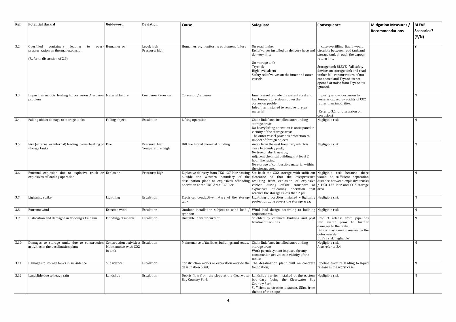
3.2 Overfilled containers leading to over-pressurization on thermal expansion (Refer to discussion of 2.4)
Human error Level: high Pressure: high
Human error, monitoring equipment failure On road tanker Relief valves installed on delivery hose and delivery line; On storage tank Trycock High level alarm Safety relief valves on the inner and outer vessels
In case overfilling, liquid would circulate between road tank and storage tank through the vapour return line. Storage tank BLEVE if all safety devices on storage tank and road tanker fail, vapour return of not connected and Trycock is not opened or noise from Trycock is ignored.
Y
3.3 Impurities in CO2 leading to corrosion / erosion problem
Material failure Corrosion / erosion Corrosion / erosion Inner vessel is made of resilient steel and low temperature slows down the corrosion problem; Inlet filter installed to remove foreign material
Impurity is low. Corrosion to vessel is caused by acidity of CO2 rather than impurities. (Refer to 3.1 for discussion on corrosion)
N
3.4 Falling object damage to storage tanks Falling object Escalation Lifting operation Chain link fence installed surrounding storage area; No heavy lifting operation is anticipated in vicinity of the storage area; The outer vessel provides protection to impact of foreign objects
Negligible risk
N
3.5 Fire (external or internal) leading to overheating of storage tanks
Fire Pressure: high Temperature: high
Hill fire, fire at chemical building Away from the east boundary which is close to country park; No tree or shrub nearby; Adjacent chemical building is at least 2 hour fire rating; No storage of combustible material within the storage area
Negligible risk N
3.6 External explosion due to explosive truck or explosives offloading operation
Explosion Pressure: high Explosive delivery from TKO 137 Pier passing outside the western boundary of the desalination plant or explosives offloading operation at the TKO Area 137 Pier
Set back the CO2 storage with sufficient clearance so that the overpressure resulting from explosion of explosive vehicle during offsite transport or explosives offloading operation that reaches the storage is less than 2 psi.
Negligible risk because there would be sufficient separation distance between explosive trucks / TKO 137 Pier and CO2 storage area.
N
3.7 Lightning strike Lightning Escalation Electrical conductive nature of the storage tank
Lightning protection installed – lightning protection zone covers the storage area;
Negligible risk N
3.8 Extreme wind Extreme wind Escalation Outdoor installation subject to wind load / typhoon
Wind load design according to building requirements.
Negligible risk N
3.9 Dislocation and damaged in flooding / tsunami Flooding/ Tsunami Escalation Unstable in water current Shielded by chemical building and post treatment facilities
Product release from pipelines into water prior to further damages to the tanks; Debris may cause damages to the outer vessels; BLEVE risk negligible
N
3.10 Damages to storage tanks due to construction activities in the desalination plant
Construction activities; Maintenance with CO2 in tank
Escalation Maintenance of facilities, buildings and roads. Chain link fence installed surrounding storage area; Work permit system imposed for any construction activities in vicinity of the tanks;
Negligible risk, Also refer to 3.4
N
3.11 Damages to storage tanks in subsidence Subsidence Escalation Construction works or excavation outside the desalination plant;
The desalination plant built on concrete foundation;
Pipeline fracture leading to liquid release in the worst case.
N
3.12 Landslide due to heavy rain Landslide Escalation Debris flow from the slope at the Clearwater Bay Country Park
Landslide barrier installed at the eastern boundary facing the Clearwater Bay Country Park; Sufficient separation distance, 55m, from the toe of the slope
Negligible risk N
5
Ref. Potential Hazard Guideword Deviation Cause Safeguard Consequence Mitigation Measures /
Recommendations
BLEVE
Scenarios?
(Y/N)
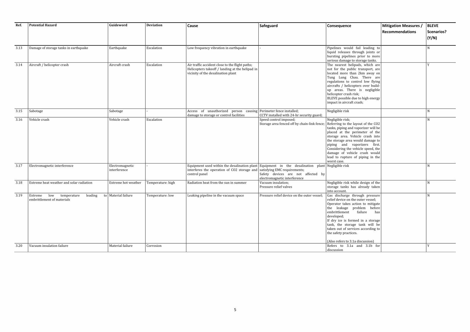
3.13 Damage of storage tanks in earthquake Earthquake Escalation Low frequency vibration in earthquake - Pipelines would fail leading to liquid releases through joints or bursting pipelines prior to more serious damage to storage tanks.
N
3.14 Aircraft / helicopter crash Aircraft crash Escalation Air traffic accident close to the flight paths; Helicopters takeoff / landing at the helipad in vicinity of the desalination plant
The nearest helipads, which are not for the public transport, are located more than 2km away on Tung Lung Chau. There are regulations to control low flying aircrafts / helicopters over build-up areas. There is negligible helicopter crash risk; BLEVE possible due to high energy impact in aircraft crash;
Y
3.15 Sabotage Sabotage - Access of unauthorized person causing damage to storage or control facilities
Perimeter fence installed; CCTV installed with 24-hr security guard;
Negligible risk N
3.16 Vehicle crash Vehicle crash Escalation Speed control imposed; Storage area fenced off by chain-link fence;
Negligible risk; Referring to the layout of the CO2 tanks, piping and vaporizer will be placed at the perimeter of the storage area. Vehicle crash into the storage area would damage to piping and vaporizers first. Considering the vehicle speed, the damage of vehicle crash would lead to rupture of piping in the worst case.
N
3.17 Electromagnetic interference Electromagnetic interference
- Equipment used within the desalination plant interferes the operation of CO2 storage and control panel
Equipment in the desalination plant satisfying EMC requirements; Safety devices are not affected by electromagnetic interference
Negligible risk N
3.18 Extreme heat weather and solar radiation Extreme hot weather Temperature: high Radiation heat from the sun in summer Vacuum insulation; Pressure relief valves
Negligible risk while design of the storage tanks has already taken into account.
N
3.19 Extreme low temperature leading to embrittlement of materials
Material failure Temperature: low Leaking pipeline in the vacuum space Pressure relief device on the outer vessel;
Gas discharge through pressure relief device on the outer vessel; Operator takes action to mitigate the leakage problem before embrittlement failure has developed; If dry ice is formed in a storage tank, the storage tank will be taken out of services according to the safety practices. (Also refers to 3.1a discussion)
N
3.20 Vacuum insulation failure
Material failure Corrosion Refers to 3.1a and 3.1b for discussion
Y

6
Ref. Potential Hazard Guideword Deviation Cause Safeguard Consequence Mitigation Measures /
Recommendations
BLEVE
Scenarios?
(Y/N)
3.21 Pressure building system failure Pressure buildup Pressure: low / high Valve to pressure building system fails to open due to malfunction; Valve to pressure building system fails to close due to malfunction;
Monitoring through pressure gauge and temperature gauge and low pressure alarm; Pressure relief devices on inner and outer vessels
Fail to open valve to the pressure building coil Pressure at vapour space too low below 4 bar leading to dry ice formation; Fail to close valve to the pressure building coil Pressure build-up in the vapour space leading to venting through safety valves. Risk of BLEVE is considered as failure of pressure build-up system and pressure relief devices and alarm system at the same time.
Y
4 DRAWOFF & DOSAGE SYSTEM
4.1 Failure of liquid line Material failure Corrosion Excessive liquid withdrawal causes dry ice formation in pipeline leading to overpressure
Line pressure relief valve;
Liquid discharge through bursting pipeline and formation of dry ice in the worst case; Risk of BLEVE negligible;
N
4.2 Failure of vapor line Material failure Corrosion Spontaneous failure - Pressurized gas release; Since vapour phase release is involved, dry ice plug will not form; Risk of BLEVE negligible
N
4.3 Flow regulation valve failure Material failure Flow: high Material fault Pressure sensor after vaporizer; Dual regulators to ensure the reliability; Temperature monitor after the vaporizer; Flowmeter monitor flowrate; Safety valves upstream and downstream of the regulators
Excessive flow rate leading to low temperature condition at downstream pipeline; Risk of damage to downstream system negligible.
N
4.4 Formation of ice at radiators of vaporizers - Temperature: low Flow: high
Low temperature ambient conditions; Usage exceeds the capacity
Low temperature protection installed on the pipeline;
Low temperature condition at downstream pipeline; Risk of damage to downstream system negligible.
N
5 GAS DISPERSION SYSTEM
5.1 Vapor line failure Material failure Corrosion Spontaneous failure - Indoor gas release; asphyxiation effect to operating staff.
CO2 / O2 sensor for indoor installation; Venting should be undertaken outdoor; Mechanical ventilation should be provided for indoor environment.
N

Dwg.1 Layout Plan of the Desalination Plant
Indicative Alignment of Chemical Pipes Indicative Alignment of Sodium Hypochlorite Pipes Access Road for CO2 Road Tankers

Dwg. 2 Indicative Layout of CO2 Storage Tanks
Remarks: only part of the total storage capacity is shown

Road tanker
Storage tank
vaporizer Dosing system
Mixer
Treated water
product water
Vapour return
Liquid filling
Liquid drawing
Desalination Plant
Linde HKO
Dwg. 3 Sub-systems
Gas dispersion system Draw-off & dosage system Storage tank and pressure build-up system
Transfer system
Transport subsystem
Transport onsite & offsite

Dwg.4 Typical Storage Tank Flow Diagram
Remarks: This is only a typical schematic figure of CO2 storage tank. For CO2 storage tanks in the Desalination Plant, there will be 2 pairs of independent pressure relief valves (PRVs) installed on inner vessel. High level alarms will be installed and routed to control room to warn the operators when the tanks are overfilled.
Temperature gauge may be installed to enhance the monitoring capability for operating conditions.
12
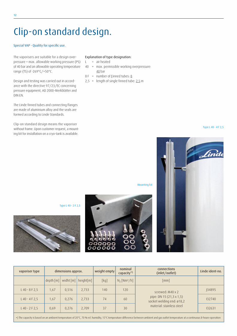
The vaporisers are suitable for a design over-
pressure = max. allowable working pressure (PS)
of 40 bar and an allowable operating temperature
range (TS) of -269°C/+50°C.
Design and testing was carried out in accord-
ance with the directive 97/23/EC concerning
pressure equipment, AD 2000-Merkblätter and
DIN EN.
The Linde finned tubes and connecting flanges
are made of aluminium alloy and the seals are
formed according to Linde Standards.
Clip-on standard design means the vaporiser
without frame. Upon customer request, a mount-
ing kit for installation on a cryo-tank is available.
Explanation of type designation:
L = air heated
40 = max. permissible working overpressure:
40 bar
8 F = number of Finned tubes: 8
2,5 = length of single finned tube: 2,5 m
Type L 40 - 2 F 2,5
vaporiser type dimensions approx. weight empty Linde ident-no.
depth [m] widht [m] height[m] [kg] N2 [Nm³/h] [mm]
L 40 - 8 F 2,5 1,67 0,516 2,733 140 120 J34895
L 40 - 4 F 2,5 1,67 0,276 2,733 74 60 I32740
L 40 - 2 F 2,5 0,69 0,276 2,709 37 30 I32631
*) The capacity is based on an ambient temperature of 20°C, 70 % rel. humidity, 15°C temperature difference between ambient and gas outlet temperature at a continuous 8-hours-operation
screwed: M40 x 2pipe: DN 15 (21,3 x 1,5)
socket welding end: ø18,2material: stainless steel
nominalcapacity*)
connections(inlet/outlet)
Type L 40 - 4 F 2,5
Mounting kit
Special VAP - Quality for specific use.
Clip-on standard design.

8
Figure 4 Typical Schematic of Vacuum Insulated Tanker
Source: EIGA, Road Vehicle Emergency and Recovery, IGC Doc 81/06/E
Remarks: This is only a typical schematic figure of vacuum insulated tanker. For CO2 road tankers used in the Desalination Plant, there will be 2 pairs of independent pressure relief valves (PRVs) installed on inner vessel.