Embed Size (px)
Citation preview

M. Ali et al. (Eds.): IEA/AIE 2013, LNAI 7906, pp. 421–430, 2013. © Springer-Verlag Berlin Heidelberg 2013
Hazard Identification of the Offshore Three-Phase Separation Process Based on Multilevel Flow Modeling and HAZOP
Jing Wu1,*, Laibin Zhang1, Morten Lind2, Wei Liang1, Jinqiu Hu1, Sten Bay Jørgensen3, Gürkan Sin3, and Zia Ullah Khokhar4
1 College of Mechanical and Transportation Engineering, China University of Petroleum, Beijing, China
[email protected] {zhanglb,lw,hujq}@cup.edu.cn
2 Dept. Electrical Engineering, Technical University of Denmark, Lyngby, Denmark [email protected]
3 Dept. Chemical and Biochemical Engineering, Technical University of Denmark, Lyngby, Denmark
{sbj,gsi}@kt.dtu.dk 4 Dept. Environmental Engineering, Technical University of Denmark, Lyngby, Denmark
Abstract. HAZOP studies are widely accepted in chemical and petroleum industries as the method for conducting process hazard analysis related to design, maintenance and operation of the systems. Different tools have been developed to automate HAZOP studies. In this paper, a HAZOP reasoning method based on function-oriented modeling, Multilevel Flow Modeling (MFM), is extended with function roles. A graphical MFM editor, which is combined with the reasoning capabilities of the MFM Workbench developed by DTU is applied to automate HAZOP studies. The method is proposed to support the “brain-storming” sessions in traditional HAZOP analysis. As a case study, the extended MFM based HAZOP methodology is applied to an offshore three-phase separation process. The results show that the cause-consequence analysis in MFM can infer the cause and effect of a deviation used in HAZOP and used to fill HAZOP worksheet. This paper is the first paper discussing and demonstrate the potential of the roles concept in MFM to supplement the integrity of HAZOP analysis.
Keywords: Hazard identification, Multilevel Flow Modeling, HAZOP, automated HAZOP.
1 Introduction
In petroleum and natural gas industries, hazard identification has been advocated, and required by the government licensing authorities or clients to meet with the goals of * Corresponding author.

422 J. Wu et al.
Health, Safety and Environment Management System (HSEMS) since 1960s. Hazard identification is included in the risk management as the first stage towards identifying and formulating major accidents scenarios needed for risk calculation. Especially, oil and gas production is becoming more and more complex with the application of monitoring and detection systems such as DSC, SCADA system, whose advantage is to strengthen the ability of automatic detection to enable adjustment of the process and to enlarge the information sources for operators. But at the same time, operators have difficulties in coping with large amounts of alarms under abnormal conditions, The insufficient support by the control systems and data records leads to the situation that some hazards are not detected in time and propagated up to a higher level in operation hierarchy. So techniques for hazard identification recently have attracted much attention both from research communities and application companies [1].
The Definition of a Hazard in the Oxford Dictionary is "a thing that can be dangerous or cause damage" . How to systematically identify the hazards in an operating process and visualize the hazard propagation paths to help operators to make a wise decision under emergency situation is a big challenge faced by researchers. HAZOP developed in the late 1960s at Imperial Chemical Industries (ICI), among other available techniques aimed at identification of hazards is widely applied in situations where processing of hazardous materials take place, in oil and gas processing plant for instance. It is here important to ensure a high level of completeness of the set of deviations considered. Because hazards identification is the primary element of risk evaluation also the qualitative aspects of risk evaluation are dependent on an adequate description (in terms of cause and consequence models) of the hazards. The key issues for these aspects are completeness, consistency and correctness [2]. As a consequence, well-structured HAZOP methods are popular in particular in complex processes. However, the standard HAZOP methodology is lacking the consideration of the level and extent of decomposition of the plant into sub-systems. This is usually decided by the expert team leader, and to a large extent, the manual cause and consequence analysis of hazards depends on the experience and knowledge of the HAZOP team. Thus, in last two decades, improved HAZOP methods have successfully overcome some above problems, through development of different tools to assist the HAZOP studies, some of them are HAZOPExpert in continuous process [3], PHASuite in chemical processes [4], PetroHAZOP case-based reasoning in petroleum industries [5], CHECKUP tool [6] and Functional HAZOP assistant [7]. Among them, Functional HAZOP assistant proposed by Rossing et al. based on Multilevel Flow Modeling (MFM) represents functional knowledge with easier understanding of real system and provides a very efficient paradigm for facilitating HAZOP studies and for enabling reasoning to reveal potential hazards in safety critical operations. MFM is a qualitative reasoning model that could be used to assist the Hazop team by ensuring coverage and consistency and improve completeness. MFM divides the system into subsystems according to the functions in terms of goals, relations and components and provides a set of reasoning rules which can be used to perform automatic HAZOP study and reveal the potential hazards and the casual paths of a hazard in a visual way. MFM can in this way help operators to understand the system in functional terms and give them a basis for decision making.

Hazard Identification of the Offshore Three-Phase Separation Process 423
The purpose of this paper is to demonstrate how to apply MFM with the role concept in a case study of an offshore three-phase separation process in oil and gas industry. The remainder of this paper is organized as follows. A brief description of an offshore three-phase separation process is given in section 2. Section 3 describes after short introduction of MFM how the reference system for the present research is modeled. The hazard identification based on the HAZOP technique using the MFM editor and reasoning software is introduced in section 4. Finally, section 5 is conclusions.
2 Offshore Three-Phase Separation Process
The offshore three-phase separation process, used as a case study here, is commonly applied in offshore oil and gas industry. The process schematic is shown in Fig.1. The purpose of the separation system is to separate two flows of feed, mixture of crude, water and gas stream. Both feed flows have flow rate of 3600 kg/h, pressure of 56 bar and temperature of 50 oC. The components of the feed flows are water, methane, ethane, propane, butane, pentane, hexane, methanol, carbon dioxide, nitrogen, isobutene, isopentane, MEG, and four pseudo components representing higher number of higher number of hydrocarbons.
The two fluid streams are mixed before entering the three-phase separator, which is designed to separate the gas, as well as separate the oil and water. A safety valve provides protection against unwanted pressure buildup. The weir inside the separator maintains the oil level, and the level controller maintains the water level. The oil is skimmed over the weir. The level of the oil downstream of the weir is controlled by a level controller that operates the oil export valve. The gas flow out through a mist extractor to a pressure control valve that maintains constant vessel pressure. Then it passes to a compressor which increases the pressure of the export gas, which is driven by a variable motor speed. At the outlet side of the compressor a heat exchanger is connected with water as cooling medium. The cooler is regulated by a temperature control loop. Also an anti-surge controller loop is installed to protect the compressor from entering a surge condition. More details about the process can be found in [8].
Fig. 1. Simplified P&ID of three-phase separation process

424 J. Wu et al.
3 Multilevel Flow Modeling
3.1 Introduction of Multilevel Flow Modeling
Multilevel Flow Modeling (MFM) is one of the representative functional modeling methods, used to represent goals and functions of process plants involving interactions between flows of material, energy and information. Fault management of complex plants is one of the most effective and developed applications fields [9]. The concepts and symbols of MFM are shown in Fig.2.
Qualitative reasoning in an MFM model is based on representation of process knowledge on several levels of specification. The explanations generated by the model can be directly visualized in the MFM models, represented later in case study. Details concerning the automated reasoning rules about causes and consequences can be found in [10]. A newly updated MFM editor, a graphical editor, supporting the MFM method, in combination with the reasoning capabilities of the MFM Workbench developed by the Technical University of Denmark, will be used to analyze separation process equipment deviations, their root causes, and their possible consequences.
Fig. 2. The basic MFM symbols
3.2 MFM Model of Three-Phase Separation Process
Before to building the MFM model, the following subsystems are defined:
1. Feed Subsystem (FS). Goal: To provide a mixture of crude, water and gas stream to the three-phase separator (23VA0001), from the feed source to the inlet piping of separator, including the two choke valves (25HV0001 and 25 HV 0002), and one inlet isolation valve (25ES0001).
2. Separation Subsystem (SS). Goal: To separate a mixture of oil, water and gas stream. Node 1, Function: Water transport. From water outlet of separator to the water sink including the separator water level control valve (23LV0001) and related instrumentation. Node2, Function: Oil transport. From the oil outlet of separator to the oil sink including a centrifugal pump(23PA0001), motor (23EM0001) and water dump valve (23MV0003), oil level control valve(LV0002) and related instrumentation.

Hazard Identification of the Offshore Three-Phase Separation Process 425
Node3, Function: Gas transport. From the gas outlet of the separator back to the inlet of separator including compressor 23KA0001, motor 23EM0002 and heat exchanger (23HX0001)
3. Heat Removal Subsystem (HRS). Goal: To transport the heat inside the gas to the environment.
An overall MFM model for this three-phase separation process is shown in Fig.3. In the following we will explain the MFM model by each flow structure representing functions of the subsystems.
Fig. 3. MFM model of the three-phase separation process
3.2.1 Mass Flow Structures In the flow structure mfs 1(total feed system massflow partA), the source sou1 represents a mixture flow of crude, water and gas stream. The function tra1 represents the transportation of the mixture flow realized by pipe and choke valve, connected with feed source by an influence relation since it influences the flow rate of pipe. And the balance bal1 represents the function of pipe between choke valve and the inlet isolation valve. The function tra4 represents the transport of mixture of crude oil, water and gas steam; finally the mixtures would flow into three phase separator, with a participant (pa4).
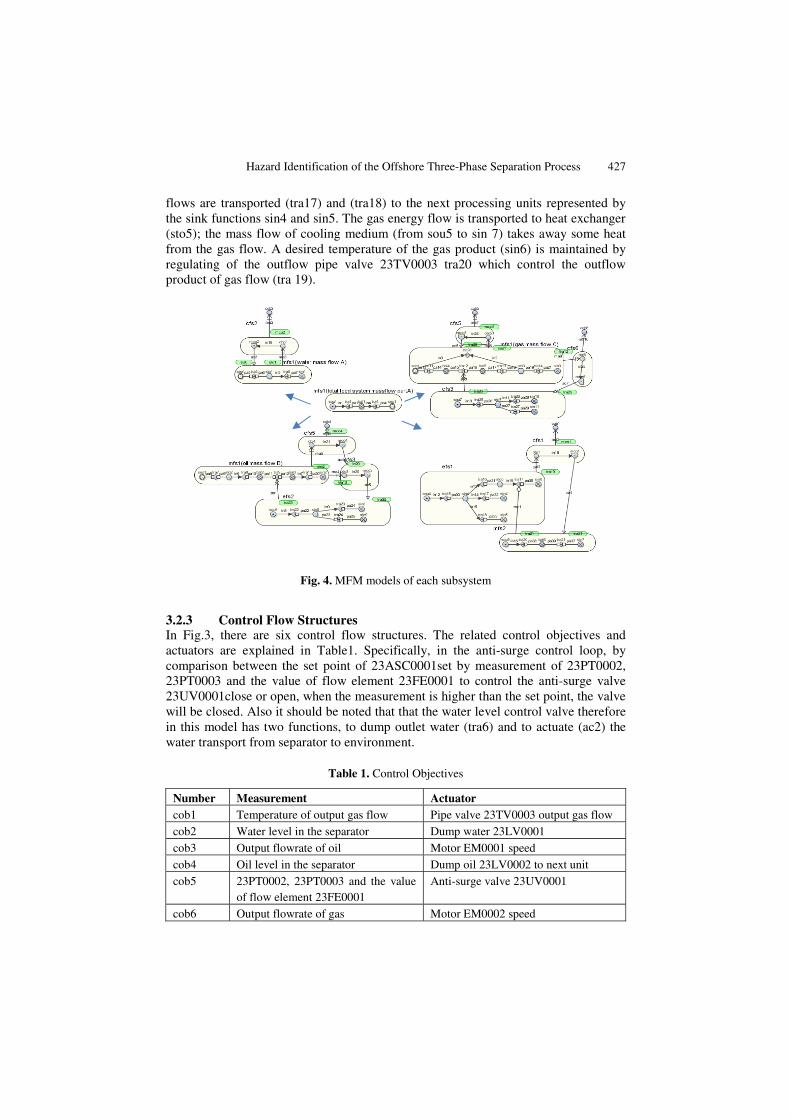
The flow structure mfs1 (water mass flow A) in the top left corner of Fig.4: After being separated by the three phase separator sep1, the water is transported (tra5) to the

426 J. Wu et al.
water chamber represented by the storage function sto1. The separator and the transport are related by a participant relation since it is assumed not to influence the flow of water. The transport function is also connected by a participant relation pa6 with the function sto1 representing the storage of water provided by the water chamber since the state of the storage (amount of water) cannot influence the flow of water transported (tra5). The function tra6 represents the transfer of water out of the water chamber of the separator provided by outlet pipe, including the water level control valve (LV0001). It is connected with an influence to sto1 since the level of water influences the transfer of water out of water chamber of the separator.
The flow structure mfs1 (oil mass flow B) in the bottom left corner of Fig.4: After being separated by the three phase separator sep1, the oil is transported (tra7) to the oil chamber whose function is represented by sto2. Similarly, the separator and the transport are related by a participant relation since it is assumed not to influence the flow of water. The transport function is also connected by a participant relation pa9 with the function sto2 representing the storage of water provided by the oil chamber since the state of the storage (amount of oil) influences the flow of oil transported by tra7. The function tra8 represents the transport of oil out of the oil chamber of the separator provided by outlet pipe, including the pipe flow rate control valve (25MV0003).Then through pipe (represented by the balance function bal2) it is connected to the transport of oil (tra9) provided by oil export pump (23PA0001), which is connected with efs2 by a producer-product relation pp1. The relation pp1 is labeled with tra22, which represents the electrical power of motor (sou6) supplied to the pump (sto6) so that the oil flow rate tra9 can be maintained at its desired value represented by the objective obj3. Tra23 and tra24 represents transfer of the energy into kinetic energy of the oil (tra23 and sin8) and friction losses in the circulation loop (tra24 and sin9). The balance bal3 represents the function of the pipe between the pump and oil level control valve tra 10(LV0002) It is connected with an influence to bal3 since the level of oil influences the transfer of oil out of oil chamber of the separator.
The flow structure mfs1 (gas mass flow C) in the top right corner of Fig.4: After being separated by the three phase separator sep1, the gas is transported (tra11) (25 ES0002) through pipe (bal4) into compressor 23KA0001. Similarly, the compressor is also driven by motor EM0002 and obtains its driving energy from the energy flow structure efs3, whose energy transformation can be referred to the flow structure efs2. The control flow structure cfs6 represents the regulation of the motor speed control the compressor. Then the gas flows through pipe (tra13) between the compressor and heat exchanger whose function here is represented by sto3. The gas production is exported out of the heat exchanger from the outlet pipe and pipe volume valve 25 ES0005 (tra14) to the next gas processing unit.
3.2.2 Energy Flow Structures The energy flow structure efs1 describes the total energy flow transported from the feed subsystems to the final products. The source function (Sou 4) represents the total energy carried by mixture flow of crude, water and gas steam, which is transported (tra15) to three-phase separator (sto4). Then the energy contained in the oil and water
Hazard Identification of the Offshore Three-Phase Separation Process 427
flows are transported (tra17) and (tra18) to the next processing units represented by the sink functions sin4 and sin5. The gas energy flow is transported to heat exchanger (sto5); the mass flow of cooling medium (from sou5 to sin 7) takes away some heat from the gas flow. A desired temperature of the gas product (sin6) is maintained by regulating of the outflow pipe valve 23TV0003 tra20 which control the outflow product of gas flow (tra 19).
Fig. 4. MFM models of each subsystem
3.2.3 Control Flow Structures In Fig.3, there are six control flow structures. The related control objectives and actuators are explained in Table1. Specifically, in the anti-surge control loop, by comparison between the set point of 23ASC0001set by measurement of 23PT0002, 23PT0003 and the value of flow element 23FE0001 to control the anti-surge valve 23UV0001close or open, when the measurement is higher than the set point, the valve will be closed. Also it should be noted that that the water level control valve therefore in this model has two functions, to dump outlet water (tra6) and to actuate (ac2) the water transport from separator to environment.
Table 1. Control Objectives
Number Measurement Actuator cob1 Temperature of output gas flow Pipe valve 23TV0003 output gas flow cob2 Water level in the separator Dump water 23LV0001 cob3 Output flowrate of oil Motor EM0001 speed cob4 Oil level in the separator Dump oil 23LV0002 to next unit cob5 23PT0002, 23PT0003 and the value
of flow element 23FE0001 Anti-surge valve 23UV0001
cob6 Output flowrate of gas Motor EM0002 speed

428 J. Wu et al.
4 Automatic Reasoning of MFM Model with MFM Editor
4.1 Functions-Based Reasoning
We assume that there is a deviation of flow of gas in outlet pipe from separator i.e. the transport function is in a state of loflow (tra11, loflow) in Fig.3 This will possibly lead to the occurrence of a compressor surge. The possible causes identified by the MFM reasoning engine using the model above are shown below in Fig.5.
Fig. 5. Possible causes identified by the MFM reasoning engine (left) and Extended MFM model of water mass flow A with roles (right)
Bal4 fill: Low flow through the inlet of compressor (bal4 fill, primary cause), for example, the inlet filter plugging.
Tra12 loflow: Low flow of gas through compressor (tra12 loflow, primary cause) caused by low flow passed through the flow or impeller channel in compressor (bal5 fill, secondary cause) or low conversion of the energy into kinetic energy in compressor (tra26 loflow, secondary cause) or outlet pipe of compressor partly blocked (tra 13 loflow, secondary cause), for example, the pipe network resistance increased. The low conversion of the energy into kinetic energy in compressor caused by the low driven power stored in compressor (sto7 lovol, tertiary cause) or the overload of compressor (sin 10 hivol, tertiary cause). The low driven power stored in compressor (sto7) is caused by the low energy transported (tra25 loflow, quaternary cause), which is originally rooted in low speed of the compressor motor (sou7 lovol, quintuple cause). The low gas flow in pipe (tra13) between compressor and heat exchanger is caused by the high level in the heat exchanger tube (sto3 hivol, tertiary cause), which is originated from UV0001 valve partly closed (tra28 loflow, quaternary cause) or 25ES005 valve partly closed (tra14 loflow, quaternary cause), which is due to the gas production above the quota (sin3 hivol, quintuple cause), in another word, the overmuch deduction of gas production.
The HAZOP table of this deviation is summarized in Table 2.
4.2 Introducing Roles
In order to identify the relations between function and structure, the concept of roles have been introduced in MFM. The representation of roles in MFM is discussed in [11]. However, presently there is no agreement about which and how many roles are needed and no consensus has been reached on nature of the roles. However, the

Hazard Identification of the Offshore Three-Phase Separation Process 429
extension of MFM with roles (agent, object, instrument etc.) may endow the potential for identifying hazards that are not only described with guide words in HAZOP studies such as ”more", "less", "none" which is discussed above and applied in [7], but also other guide words such as" part of ", "as well as", "other than".
In the case of the three-phase separator, we will apply a patient role r1 and an agent role r2 on the separation function. The patient and the agent here mean the entity undergoing the effect of some action and the doer of the action, respectively. Specifically, in the sentence "the separator separates the mixture flow of crude oil, water and gas stream", the separator has the agent role and the mixture flow of crude oil, water and gas stream has the patient role. A patient role is adopted here instead of object role proposed in [11] because the mixture flow undergoes a change of phases and being processed by the separator, and also the separation effect is dependent on the properties of the mixture flow and agent role separator. It is suggested to distinguish between object and patient roles. When only the extrinsic properties (like location) and not the intrinsic properties of a physical are changed by the action the item is an object of the action. For example, when water is transported by a pipe, the water has an object role since it is moved from one place to another place by the agent (the pipe) without any state change. The patient role is different and very important because it allows the identification of possible hazards caused by the change of properties (composition, temperature, pressure) in mass or energy flow.
Table 2. HAZOP analysis of a deviation of flow of gas in outlet pipe from separator
Function node Deviation Possible root causes Possible
consequence
Safety measurement
Transport 11
Low
gas
flow
1.The inlet filter plugging
Compressor
surge
occurring
1.Inlet gas flow pressure transmitter
23PT0002
2.Low flow passed through the flow or
impeller channel in compressor
2.Outlet gas flow pressure
transmitter 23PT 0003
3.Low speed of the compressor motor 3.Monitoring he speed of
compressor motor
4.Overload of compressor 4.Improve the load capacity of the
compressor
5.UV0001 valve partly closed 5. Checking the anti-surge
controller 23ASC0001
6. Overmuch deduction of gas production 6.Increase gas production
5 Conclusions
The paper has presented a model of an offshore three-phase separation process. It is shown that the principles of Multilevel Flow Modeling for representing mass and energy flow functions and control system functions can be successfully applied for a complex system in oil and gas industries. Also it demonstrates that the MFM functional modeling can cover shortages of standard HAZOP methodology. The

430 J. Wu et al.
use of the automatic cause-consequence reasoning mechanism of MFM for HAZOP based on parameter deviations and hazards conditions are investigated. The role concept in MFM may be helpful for detecting hazards in lower hierarchy in HAZOP studies. This method provides a basis for key facilities in oil and gas industries for safe operation of the three-phase separation process.
Acknowledgements. The first author is thankful to China Scholarship Council (CSC), Ministry of Education (File No. 201206440002) for the grant of a scholarship for one year and the support from the research groups at Department of Electrical Engineering and Department of Chemical and Biochemical Engineering at DTU. This project is also supported by National Science and Technology Major Project of China (Grant No. 2011ZX05055); National Natural Science Foundation of China (Grant No. 51104168); PetroChina Innovation Foundation (Grant No. 2011D-5006-0408) and Excellent Doctoral Dissertation Supervisor Project of Beijing Grant YB20101141401.
References
1. Dunjó, J., Fthenakis, V., Vílchez, J.A., Arnaldos, J.: Hazard and operability (HAZOP) analysis. A literature review. . Journal of hazardous materials 173(1), 19–32 (2010)
2. Rushton, A.G.: II. 3 Hazard identification techniques. Industrial Safety Series 6, 129–161 (1998)
3. Venkatasubramanian, V., Zhao, J., Viswanathan, S.: Intelligent systems for HAZOP analysis of complex process plants. Computers & Chemical Engineering 24(9-10), 2291–2302 (2000)
4. Zhao, C., Bhushan, M., Venkatasubramanian, V.: PHASuite: An automated HAZOP analysis tool for chemical processes. Part I. Knowledge engineering framework. Process Safety and Environmental Protection 83(6), 509–532 (2005)
5. Zhao, J., Cui, L., Zhao, L., Qiu, T., Chen, B.: Learning HAZOP expert system by case-based reasoning and ontology. Computers & Chemical Engineering 33(1), 371–378 (2009)
6. Palmer, C., Chung, P.W.H.: An automated system for batch hazard and operability studies. Reliability Engineering & System Safety 94(6), 1095–1106 (2009)
7. Rossing, N.L., Lind, M., Jensen, N., Jørgensen, S.B.: A functional HAZOP methodology. Computers & chemical engineering 34(2), 244–253 (2010)
8. KONGSBERG K-Spice® Tutorial, Training Manual, May 2012 © Kongsberg Oil & Gas Technologies AS
9. Lind, M.: An introduction to multilevel flow modeling. Nuclear Safety and Simulation 2(1), 22–32 (2011)
10. Lind, M.: Reasoning about causes and consequences in multilevel flow models. In: Proc. European Safety and Reliability Conference (ESREL) 2011 Annual Conference, pp. 18–22 (2011)
11. Lind, M.: Knowledge representation for integrated plant operation and maintenance. In: Seventh American Nuclear Society International Topical Meeting on Nuclear Plant Instrumentation, Control and Human-Machine Interface Technologies (2010)