Embed Size (px)
Citation preview

The Science of Audio - a series of lectures by Floyd E. Toole, Ph.D. Vice President Acoustical Engineering Harman International Industries, Inc. 8500 Balboa Boulevard, Northridge, CA 91329 818 895 5761 [email protected]
31 January, 2002 1
Loudspeakers and Rooms for
Multichannel Audio Reproduction
by Floyd E. Toole
Vice President Acoustical Engineering Harman International
Part 3 – Getting the Bass Right Choosing the number and locations of subwoofers, and determining where to sit, are fundamental to good bass. Multichannel audio should be shared, so we try to get good bass at several locations. Acoustical knowledge is essential, but EQ can help.
123
The Rules for Good Sound inRooms
At middle and high frequencies:ü Start with a loudspeaker that was designed to
function well in a variety of different rooms.ü Use geometry, reflection, diffusion, and absorption to
achieve good imaging and ambiance.At low frequencies:Ø Maximize the output from the subwoofer(s).Ø Achieve a uniform performance over the listening
area.Ø Equalize to achieve good performance.
So, we think that we know how to pick a good loudspeaker, and with some simple acoustical devices or smart design, we can avoid destructive reflections in a room. Now, what about low frequencies, the ones where the room is the dominant factor? The first task is to locate the subwoofer where it radiates most effectively. Closed box or reflex (ported) woofers are pressure sources. It matters not which way the diaphragm faces because all such loudspeakers are omni-directional at low frequencies. Obviously, there needs to be ‘breathing’ space if we choose to face the diaphragm against a wall. And, if there is a port, don’t plug it!
124
Solid Angle VLF Gains4π steradians = full sphere = ref. level
= suspended in free space2π steradians = 1/2 sphere = +6dB SPL
= on floorπ steradians = 1/4 sphere = +12dB SPL
= on floor against wallπ/2 steradians = 1/8 sphere = +18dB SPL
= on floor in corner
However, where we place the woofer with respect to the adjacent room boundaries does matter. The least effective location is in the middle of a room. It gets better on the floor, still better on the floor against a wall, and best in a corner. This is “best” in the sense of maximizing the quantity of bass radiated into the room.
harman / kardon

The Science of Audio - a series of lectures by Floyd E. Toole, Ph.D. Vice President Acoustical Engineering Harman International Industries, Inc. 8500 Balboa Boulevard, Northridge, CA 91329 818 895 5761 [email protected]
31 January, 2002 2
125
Measurements in a “Partial” Room
20 50 100 500 1K 5K 10K 20KFREQUENCY (Hz)
dB
20
30
10
0
-10
4π π * π/2 *
* INFLEXIBLE SURFACES
THE SUBWOOFER REGION
In theory we should be able to get huge gains from corner placement, and the test shown in the slide indicates that, if conditions are right, the gains are there. In real houses, the gains are a lot less, because of flexible room boundaries, open archways, etc. Still, even a 3 dB gain doubles the acoustical power into the room, and that is equivalent to adding a second woofer. Not bad, and it's free.
126
A Subwoofer in a Corner
• Produces the maximum possible LF output.– This is good
• Energizes all of the room modes– This can be good or bad, depending on the
room, and how it is arranged.
CONCLUSION: Start with the sub in acorner, and move it only if necessary.
However, as they say, there is no free lunch. Corner locations excite every resonance in the room. This may or may not be bad. You will learn how to know the difference before we are through. If it is good for a particular room, then leave it alone and move on to the next problem. If not, find a better location. However, a corner is a logical starting location. For many simple installations, an unequalized single woofer in a corner can work very well indeed. In fact, I am listening right now to just such a system in my office/den.
127
The Rules for Good Sound inRooms
At middle and high frequencies:ü Start with a loudspeaker that was designed to
function well in a variety of different rooms.ü Use geometry, reflection, diffusion, and absorption to
achieve good imaging and ambiance.At low frequencies:ü Maximize the output from the subwoofer(s).Ø Achieve a uniform performance over the listening
area.Ø Equalize to achieve good performance.
A multichannel audio system is intended to be a social experience, shared among several listeners. It is not like stereo, an antisocial experience, if it is to be heard properly. We need to try to create a situation in which as many listeners as possible hear essentially the same sound.
128
The problem here is Standing Waves,Room Resonances, Room Modes,
Eigentones, etc.
These are all the same phenomenon.
Most rooms “boom”. They have their own bass personalities. It is simply not possible to listen to the true bass output from a loudspeaker unless it is done in an anechoic space, and at very low frequencies, that means outdoors. What we hear indoors, also includes the room, and the positional factors within it.
129
Classes of Room Modes
• AXIAL: occurring between oppositeparallel surfaces
LENGTH
WIDTH
HEIGHT
Sound reflects back and forth between two parallel surfaces. At certain frequencies the incident and reflected sounds conspire to form “standing waves” in which those frequencies can be amplified, and what we hear at those frequencies depends on where we and the speakers are located. These are axial modes, since they exist along the major axes of the room.

The Science of Audio - a series of lectures by Floyd E. Toole, Ph.D. Vice President Acoustical Engineering Harman International Industries, Inc. 8500 Balboa Boulevard, Northridge, CA 91329 818 895 5761 [email protected]
31 January, 2002 3
130
Classes of Room Modes
• TANGENTIAL: occurring among foursurfaces, avoiding two that are parallel
The cyclical reflected patterns can include two, four or more surfaces. If four are involved, we call them tangential modes. Since some sound is absorbed at each reflection, generally the tangential modes are less powerful than the axial modes, which include only two reflections per cycle.
131
Classes of Room Modes
• OBLIQUE: occurring among any and allsurfaces
Oblique modes can involve any and all surfaces. They tend, therefore, to be the least important.
132
In Terms of Causing AudibleProblems:
AXIAL MODES are the dominant factor!
TANGENTIAL MODES can be significant in rooms withvery stiff/massive boundaries
OBLIQUE MODES are rarely, if ever, relevant
133
What is a Standing Wave?
+
-Pressure
Time = 0
Distance = 1/2 wavelength = 1/2λ
Total
The simplest of the standing waves, the axial modes, exist between two parallel reflecting surfaces. In this slide shown here, imagine that the two vertical lines represent walls in a room. Imagine a woofer against the left-hand one, radiating a pure tone – a sine wave – as shown. If the right wall were not present, the sine wave would simply propagate away. With the wall in place, the portion of the sine wave that would have moved on to the right is reflected back towards the source. The walls here are separated by exactly one-half wavelength, so the reflected sound wave is identical to the incident wave – they overlap perfectly. When added they make the “total” sound wave shown. Remember, this is a “stop action” view.
134
Standing Waves
+
-
P
Time = 0D = 1/2 wavelength = 1/2λ
Total
Here is the same instant in time expanded in scale.

The Science of Audio - a series of lectures by Floyd E. Toole, Ph.D. Vice President Acoustical Engineering Harman International Industries, Inc. 8500 Balboa Boulevard, Northridge, CA 91329 818 895 5761 [email protected]
31 January, 2002 4
135
Standing Waves
+
-
P
Time = + 1/8λ
Total
Here, we have done a very, very quick “play” and “pause”, stopping the action one-eighth of a wavelength later. Now the incident and reflected waves have different shapes, but the “total” is much the same, only a bit lower in amplitude. Interestingly it still crosses zero pressure half way between the walls.
136
Standing Waves
+
-
P
Time = + 1/4λ
Total
This is another 1/8 wavelength later, or ¼ wavelength from where we started. The instantaneous sound pressure is zero everywhere.
137
Standing Waves
+
-
P
Time = + 3/8λ
Total
Moving on yet another 1/8 wavelength, we note that the total waveform has “flipped” polarity, like a see-saw pivoting at the half-way point across the room. Still no sound at the mid point.
138
Standing Waves
+
-
P
Time = + 1/2λ
Total
At the half-wave stop-action view, we are precisely in a situation that mirrors where we began. If we continued for the remaining half wave, we would end up where we started. So, for the frequency at which the room dimension is precisely one-half wavelength, there will be a resonance, and a standing wave in which the sound pressure is always zero at the mid point between the reflecting surfaces. On either side the sound gets louder as one moves towards the walls. Note, that the instantaneous polarity of the pressure change is opposite on opposite sides of the pressure minimum, or null. This is important. Remember it.
139
Axial Standing Waves
+
-
P
Total
Here we see a superimposition of the stop-action “total” waveforms for one complete wavelength.

The Science of Audio - a series of lectures by Floyd E. Toole, Ph.D. Vice President Acoustical Engineering Harman International Industries, Inc. 8500 Balboa Boulevard, Northridge, CA 91329 818 895 5761 [email protected]
31 January, 2002 5
140
What you hear atdifferent locations
There is minimal sound at the mid point, and the sound gets louder as we move towards the walls.
141
Orders of Axial Standing Waves
1st
Order
2nd
Order
2 x F Frequency = F
2 x F4 x F
For a given distance between reflecting surfaces, the first resonance will be at the frequency having a wavelength equal to twice the separation. If the distance is halved, the frequency is doubled. There is also a second-order resonance, or standing wave, at exactly double the first frequency, and this standing wave has two nulls. There will also be third, fourth, and so on.
142
Visualizing Standing Waves
+ -
+ +-
Sound Level
To visualize the standing waves, let us just plot the sound pressure as a function of dis tance, and remember that the polarity changes each time we cross a null.
143
Calculating the Frequencies of Modes
f = c2
nx 2 n
y 2 n
z 2
Lx L
y L
z
WHERE: c is the speed of sound: 1130 ft/sec.nx , ny ,nz are integers from 0 to, say, 5and Lx , Ly , and Lz are the length, width and height of the room in feet.
This formula allows us to calculate all of the possible resonances in a rectangular room. It is a bit frightening.
144
A Simple Way toCalculate the Axial Modes
speed of sound in ft/s 11302 x length in feet 40
f1,0,0= = = 28.25 Hz
other length modes are simple multiples of this:2 x 28 = 56 Hz, 3 x 28 = 84 Hz, 4 x 28 = 112 Hz, and so on.Then do the same for the width and height modes.
e.g. the first length mode of a room 20 feet long
can be calculated as follows:
For the majority of situations, it may be sufficient to calculate only the axial modes. If so, it is very simple. Measure the room dimensions. Multiply the length by two, and divide it into 1130 (for dimensions in feet) or 345 (for dimensions in meters). This gives this first-order resonance along that dimension. Multiply that frequency by 2 for the second-order resonance, by 3 for the third-order, and so on. Usually it is necessary only to look at the first three or four orders. Now, repeat that for each of the other two dimensions.

The Science of Audio - a series of lectures by Floyd E. Toole, Ph.D. Vice President Acoustical Engineering Harman International Industries, Inc. 8500 Balboa Boulevard, Northridge, CA 91329 818 895 5761 [email protected]
31 January, 2002 6
145
An Even Simpler Way toCalculate ALL of the Modes .
. .and to Visualize Them.
AllObliqueAxial+Tan.TangentialAll AxialHeightWidthLength
If you have a computer, it is all even easier. Just type in the dimensions, and the work is done for you. This is a little spreadsheet program that runs in Microsoft Excel for PC’s that is available for download from www.harman.com in the section “white papers”. It shows, in an easy to understand form, all of the modes in a rectangular room.
146
It has long been believed that, tobe good, a room must have a
uniform distribution of modes inthe frequency domain.
This is certainly true forreverberation chambers, wherethe notion originated. But, is it
true for listening spaces???
But what about the “ideal” room?
147
The distribution of modes in thefrequency domain is determined
by the RATIO of the roomdimensions:
Height:Width:Lengthe.g. 1:1.5:2 = 8 x 12 x 16 feet
148
Is There an “Ideal” Room Shape?
LE
NG
TH
WIDTH
4
8
8
Over the years several acoustical luminaries have lent their names to room dimensions that purport to have advantages. Do I have a favorite too?

The Science of Audio - a series of lectures by Floyd E. Toole, Ph.D. Vice President Acoustical Engineering Harman International Industries, Inc. 8500 Balboa Boulevard, Northridge, CA 91329 818 895 5761 [email protected]
31 January, 2002 7
149
Let’s Calculate Some Modes
L:W:H = 1:2:2 = 11.5 x 23 x 23 ft.
A cube withhalf-heightceiling
Everyone knows that a cube is the worst possible shape. Such a room is really impractical in any event, because the ceiling would be very high. Let’s compromise, and make the ceiling height half of the other two dimensions. It can be seen that the room resonant frequencies all line up like little soldiers on parade, with big gaps between them. The suggestion is that some frequencies will be overly accentuated, and others not adequately represented. A room should be better if it had a more uniform distribution of resonant frequencies.
150
Let’s Calculate Some Modes
L:W:H = 1:2.1:2.2 = 11 x 23.15 x 24.5 ft.
A cube withhalf-heightceiling with6% mode separation (Bonello interpretation)
It has been suggested that adjusting the room dimensions to produce a slight separation of the resonant frequencies should help. Here, a recommendation of 6% separation of frequencies has been followed, and it is seen that while the high frequencies appear to be improved, the low frequency resonances are still in closely-spaced groups with large gaps.
151
Let’s Calculate Some Modes
L:W:H = 1:2:3 = 8 x 16 x 24 ft.
Simple multiples
A room with dimensions that are simple multiples of each other produces a mixed situation. Some of the modes seem to be well separated, but others line up at certain frequencies.

The Science of Audio - a series of lectures by Floyd E. Toole, Ph.D. Vice President Acoustical Engineering Harman International Industries, Inc. 8500 Balboa Boulevard, Northridge, CA 91329 818 895 5761 [email protected]
31 January, 2002 8
152
Let’s Calculate Some Modes
L:W:H = 1:1.8:2.3 = 9 x 16 x 21 ft.
Not-so-simple multiples
Just departing from simple multiples seems to do wonders. Here the modes all seem to be quite well distributed. If this approach to room design has any merit, this room should have some audible advantages. Does it?
153
This all makes a very nice story,but does it really matter?
Maybe . . . Somewhat . . . It alldepends . . .
Oh, all right,No!
154
Why not?
• The calculations assume that all of the modes areequally energized by the loudspeakers –they are not.
• The calculations assume that all of the modes areequally heard by the listener(s) – they are not.
• The only modes that matter, are those that areinvolved in the transfer of sound energy from theloudspeakers to the listener(s).
So, how do we determine that?
The simplifying assumptions underlying these predictions make them simpler, but also simply invalidate them!
155
Important Facts About Woofers,Listeners and Standing Waves.
• Conventional woofers are sound pressuregenerators. They will “couple” to the roommodes when they are located in highpressure regions of the standing waves.
• Ears respond to sound pressure, therefore,room modes will be most audible when ourheads are located in the high pressureregions of the standing waves.

The Science of Audio - a series of lectures by Floyd E. Toole, Ph.D. Vice President Acoustical Engineering Harman International Industries, Inc. 8500 Balboa Boulevard, Northridge, CA 91329 818 895 5761 [email protected]
31 January, 2002 9
156
How To Experience the Modes inan “Ideal” Room
In order to hear the benefits of a room with “ideal” proportions, this is how it would need to be arranged. The ideal proportions were determined by looking at the distribution of all the resonances, so we need to energize them all. A woofer on the floor in one corner excites all of the room resonances. Likewise, the listener must sit with his head stuck in another corner, in order to hear all of the modes. This sounds silly, but it is true.
157
A practical listening location doesnot couple to all of the modes.
Of course, in practice, we don’t do this. We sit where we want to.
158
A practical loudspeaker locationchanges things even more.
And we place our loudspeakers where they need to go for good imaging.
159
Two loudspeakers add morecomplications.
And we listen in stereo.
160
And with five loudspeakers wehave serious complications.
If not in a multichannel format. All of those neat calculations don’t mean a thing in a situation like this! They are just an academic exercise, more window dressing.

The Science of Audio - a series of lectures by Floyd E. Toole, Ph.D. Vice President Acoustical Engineering Harman International Industries, Inc. 8500 Balboa Boulevard, Northridge, CA 91329 818 895 5761 [email protected]
31 January, 2002 10
161
The “classic” monitoringarrangement in a 20’ x 24’ room
Here is how some professionals listen, with five full range loudspeakers located according to the new European standard: center, +/- 30° and +/- 110°.
162
We have five very different basssounds, one for each channel!
10 dB
The large variations areAt low frequencies
40 dB
When a full-range signal is panned to each of the loudspeakers in turn, and measurements are made at the listening position, we find hugely different bass responses for each of the loudspeakers. The differences are a large as 40dB in this room, and the biggest ones are all at low frequencies. The reason, the woofers each have very different acoustical “coupling” to the room resonances because they are in different locations. This will be different for every different room. Again, referring back to the “circle of confusion” the bass that was heard in the control room will not be the same as that heard at home. It cannot be.
163
Signal Panned to Speaker Pairs
10 dB
Different, but not better
Attempting to improve the situation by panning the bass to pairs of loudspeakers changes things, but does not remove the problem. Anybody think that an “ideal” room can help this? An anechoic room would, but none of us would wish to live in one.
164
This is why we use bass managementand subwoofers.
The same bass sound for all channels.
And this is why bass management and subwoofers make sense. Now we can place the woofers where they perform optimally for a specific room with a specific listening position. We can place the satellites (a term that seems inappropriate for some of the large capable loudspeakers that we use in the high-passed channels) where they need to be for directional and imaging effects. In other words, we design the low-frequency portion of the system separately because rooms force us to do so. This is the only way that we can get good bass in any room, and have any hope of having similarly good bass in different rooms. Remember about preserving the art?

The Science of Audio - a series of lectures by Floyd E. Toole, Ph.D. Vice President Acoustical Engineering Harman International Industries, Inc. 8500 Balboa Boulevard, Northridge, CA 91329 818 895 5761 [email protected]
31 January, 2002 11
165
How many subwoofers?Where do we put them?
Where do we sit?
More than one subwoofer may be needed for high sound levels in large listening spaces. It’s physics. One huge box might be difficult to hide, while a number of smaller ones might be less conspicuous. But there are other considerations which become obvious as soon as we start looking in detail at room resonances.
‘Fast’ and 'Slow’ Woofers.
A digression here about the “speed” of woofers. I keep on hearing stories that small woofers are “faster” than big ones. Well, there is truth in the argument if you consider the highest frequencies they are capable of reproducing. However, if we are crossing them over at 80 Hz, for example, to use them as subwoofers, we have limited that highest frequency to be the same for all. They are then all equally “fast”. Woofers are minimum-phase devices (see Part 2). Their time-domain behavior – speed, punch, drive, pace and rhythm - can be anticipated from their frequency responses. We will soon see that rooms really mess this up and determine what we hear. As for moving mass, we use bigger motors on larger, heavier, diaphragms. It’s a “horsepower thing”.
166
A StandingWave
Calculator
Understanding what happens in rooms at low frequencies requires knowledge of what the standing waves, or resonances, are doing to us. Part of the Excel program mentioned earlier is a great help. It shows the pressure distributions for the first few axial modes along each of the room dimensions. It is available for download from www.harman.com under “white papers”.
167
Woofer Location Decides HowMuch Energy Each Mode Receives.
A woofer on the floor, against a wall, energizes allmodes along that axis.What happens if we move it forward, say, to the firstnull?
Here I show a woofer placed against a wall, where it excites all of the modes along the length of the room. Why? Because it is in a high-pressure region for all of the mo des. What happens if we move the woofer forward, to the location of the first pressure minimum?
168
Woofer Location Decides HowMuch Energy Each Mode Receives.
A pressure source located at a pressure null, orminimum, does not energize that mode.What happens if we move it forward to the second null?
That particular mode is not energized by the woofer, and it disappears. What then happens if it is moved further ahead to the next null?

The Science of Audio - a series of lectures by Floyd E. Toole, Ph.D. Vice President Acoustical Engineering Harman International Industries, Inc. 8500 Balboa Boulevard, Northridge, CA 91329 818 895 5761 [email protected]
31 January, 2002 12
169
Woofer Location Decides HowMuch Energy Each Mode Receives.
A pressure source located at a pressure null, orminimum, does not energize that mode. Note that it isthe woofer diaphragm that is the pressure source, notthe whole enclosure.
That mode ceases to be activated, but the other one returns. Woofer location determines which of the room resonances is activated, and which is not.
170
Similarly, the Listener LocationDetermines Which Modes Will Be
Heard.
A woofer on the floor, against a wall, energizes allmodes along that axis.
A listener against the opposite wall, hears all modesalong that axis. There may be too much bass.
Just as a woofer against a wall energizes all of the standing waves in that dimension, a listener with his head close to the opposite wall hears all of the modes. Just as a woofer against a wall enjoys a gain in output because of the adjacent boundary, so the ears enjoy a similar low-frequency gain. There will be too much bass!!
171
Similarly, the Listener LocationDetermines Which Modes Will Be
Heard.
For this listener, the bass is in better overall balance, buthe wonders what happened to one of the bass notes.
Moving the listener forward provokes the same problem we had when moving the loudspeaker forward. If the head is at a null, no sound will be heard from that mode.
172
Similarly, the Listener LocationDetermines Which Modes Will Be
Heard.
And here, it is a different note that has disappeared.
Different positions mean that different frequencies will be heard with sometimes very different loudness.
173
Similarly, the Listener LocationDetermines Which Modes Will Be
Heard.
And here, two of the best really low frequencies have gone away.
The Science of Audio - a series of lectures by Floyd E. Toole, Ph.D. Vice President Acoustical Engineering Harman International Industries, Inc. 8500 Balboa Boulevard, Northridge, CA 91329 818 895 5761 [email protected]
31 January, 2002 13
174
Similarly, the Listener LocationDetermines Which Modes Will Be
Heard.
But, there are several locations where happiness might bepossible.
However, there are locations that might work reasonably well.
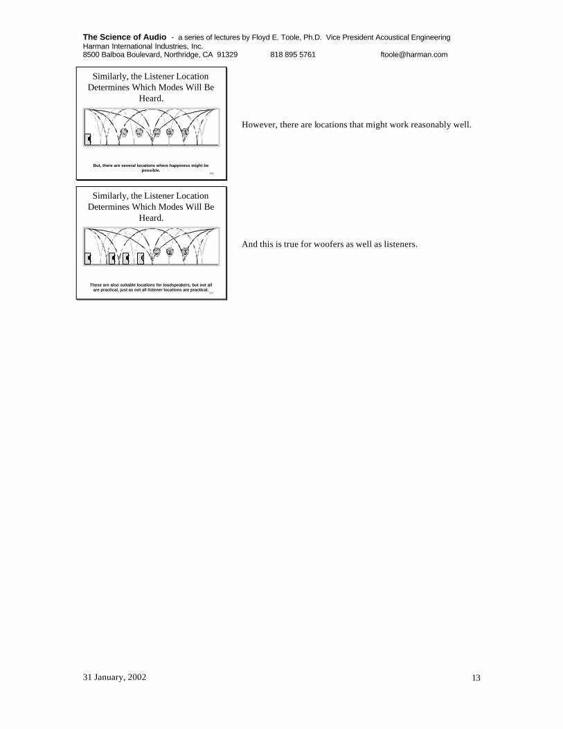
175
Similarly, the Listener LocationDetermines Which Modes Will Be
Heard.
These are also suitable locations for loudspeakers, but not allare practical, just as not all listener locations are practical.
And this is true for woofers as well as listeners.

The Science of Audio - a series of lectures by Floyd E. Toole, Ph.D. Vice President Acoustical Engineering Harman International Industries, Inc. 8500 Balboa Boulevard, Northridge, CA 91329 818 895 5761 [email protected]
31 January, 2002 14
177
0 ft. 20 ft -5 inWIDTH
Leaving only oneactive widthmode.
0 ft. 20 ft -5 inWIDTH
0 ft. 20 ft -5 inWIDTH
Does this leavenone??++
+
One subwooferenergizes allwidth modes.
Selective Mode Cancellation
0 ft. 20 ft -5 inWIDTH
+
+
+
+-
+
-
-
Two subs cancelthe odd- ordermodes.
Here we get a bit fancy. Remember the standing wave diagrams showing the “see saw” behavior of the waveform pivoting on a null. It means that at any instant in time, the sound pressures on opposite sides of a null in a standing wave are in opposite polarity. If one side is increasing, the other will be decreasing. None of this matters if we have only one source of low frequency energy in a room. However, if we have two or more, things get complicated. The top picture shows all of the width modes in a room being excited by a single subwoofer. If we place another in a symmetrical position on the other side of the room, the woofers, which receive exactly the same signal, are operating in phase (the same polarity) with each other. The first- and third- order modes, however, exhibit opposite polarities at the subwoofer locations – see the opposite polarity signs. What happens? The subwoofers couple in a destructive manner with the odd-order modes, and those modes are simply not energized. They do not exist. This leaves only one mode across the width of the room. If we get even more clever, and move the subwoofers to the null locations for that mode. They are still in opposite polarity regions for the odd-order modes, and the result is that all of the width modes are significantly attenuated, if not eliminated. Magic, no. Science, yes. So, why would we want to do this? Aha! Would it not be a good idea for everybody in each row of a home theater to hear the same bass sounds? Would it not be a good idea for a recording engineer to be able to move from one end of the console to the other without experiencing huge changes in bass? Well, this is how it can be accomplished. We are not saying, yet, that it is good sound, merely that it is the same sound. Once things are equalized in the sense of getting everybody hearing more or less the same sound, we then may need to equalize in the sense of changing the frequency response of the system.
178
2' 4'
2'3
2'8 13'4
3'88'83'8
24'3
A Practical Example:8’ x 16’ x 24’ – 1:2:3In theory, this is a bad room.
Just to prove a point, let us take a real example: a room that, by most advice should be a bad room. It is not an unusual situation. There is a living/dining room, with a rear projection television at one end, seats in the middle area, and a dining area behind the chairs.

The Science of Audio - a series of lectures by Floyd E. Toole, Ph.D. Vice President Acoustical Engineering Harman International Industries, Inc. 8500 Balboa Boulevard, Northridge, CA 91329 818 895 5761 [email protected]
31 January, 2002 15
179
It looks normal, and could happen in a detached dwelling or in an apartment.
180
Room Mode Calculatorby: Allan Devantier
dimensions length width height Cubic Volumemeters 7.32 4.88 2.44 cubic cubic
feet 24 16 8 meters feetinches 0 0 0 86.99 3072.00
all
oblique
tan & axial
tangential
axial
height
width
length 1
2
3
4
5
6
7
8
10 100 1000
Frequency (Hz)
This looks bad!
The modal distribution shows that there could be a problem with three modes stacking up at 70 Hz.
181
Along the Length of the Room
0 ft. 24 ft -0 in
3 4 8 9 12 15 16 21
LENGTH
In “theory”
Fortunately, we have some help from the locations of loudspeakers and listeners. The loudspeakers are lined up with the front of the RPTV, and that puts them in the null of the fourth-order mode. The listeners are seated at the mid point, and they are in the nulls of the first- and third-order modes.
182
0 ft. 24 ft -0 inLENGTH
Along the Length of the Room
In practice
That leaves only the second-order length mode to cause problems.

The Science of Audio - a series of lectures by Floyd E. Toole, Ph.D. Vice President Acoustical Engineering Harman International Industries, Inc. 8500 Balboa Boulevard, Northridge, CA 91329 818 895 5761 [email protected]
31 January, 2002 16
184
0 ft. 16 ft -0 in
2 2 3/4 5 1/4 6 8 10 10 3/4 14
WIDTH
Across the Width of the Room
In “theory”
In theory there are a bunch of modes at play.
185
0 ft. 16 ft -0 in
2 2 3/4 5 1/4 6 8 10 10 3/4 14
WIDTH
Across the Width of the Room
In practice – the loudspeakers, which operate ‘in phase’ at lowfrequencies, “destructively” drive the 1st and 3rd order modes(they are not energized), and they are located at the nulls of the 2 nd
order mode (it is not energized). The 4 th order width mode is“constructively” driven.
+ +
+ -+ -
In practice, we have selected locations for the loudspeakers and listeners that avoid them all.
186
0 ft. 16 ft -0 inWIDTH
Across the Width of the Room
But, the listeners are located at nulls of the 4t h order modeand it is not heard.
187
0 ft. 16 ft -0 inWIDTH
Across the Width of the Room
So, in practice, there are no active width modes in the listening path.
188
Room Mode Calculatorby: Allan Devantier
dimensions length width height Cubic Volumemeters 7 . 3 2 4.88 2.44 cubic cubic
feet 24 16 8 meters f e e ti n c h e s 0 0 0 86.99 3072.00
all
oblique
tan & axial
tangential
axial
height
width
length 1
2
3
4
5
6
7
8
10 100 1000
Frequency (Hz)
r r r
r r r r
The modal distribution looks a lot less cluttered after we cross off all of the modes that are not involved with communicating between the woofers and the listeners in those chairs. Remember, things will be different elsewhere in the room.

The Science of Audio - a series of lectures by Floyd E. Toole, Ph.D. Vice President Acoustical Engineering Harman International Industries, Inc. 8500 Balboa Boulevard, Northridge, CA 91329 818 895 5761 [email protected]
31 January, 2002 17
189
And, finally, the height dimension
In practice: the ears are close to the nulls for the 1 st and 3 rd order modes. They are not eliminated, but are seriously attenuated.
190
Room Mode Calculatorby: Allan Devantier
dimensions length width height Cubic Volumemeters 7 . 3 2 4.88 2.44 cubic cubic
feet 24 16 8 meters f e e ti n c h e s 0 0 0 86.99 3072.00
all
oblique
tan & axial
tangential
axial
height
width
length 1
2
3
4
5
6
7
8
10 100 1000
Frequency (Hz)
r r r
r r r r
r r
What problem?
This one might be a problembecause it is so lonely. 47 Hz, let’s have a look.
When we are through, there is only one solitary room resonance that is actively involved in the acoustical link from the loudspeakers to the listeners. Amazing! Let’s measure it and see what we have.
191
And guess what we found?
47 Hz!
80 Hz crossover
3 coincident nulls
Surprise, surprise. There is a resonance at 47 Hz, the frequency of the remaining second-order length mode. And, guess what, there is a sharp dip at 70 Hz, just where we successfully canceled those problematic modes. To get rid of the dip, all we need to do is to be less successful at canceling some of those modes. In other words, move a chair or a loudspeaker a few inches.
192
A simple fix
BEFORE andAFTER one bandof parametric EQ
And, what about the resonant peak? When we listened, it was clearly audible, making kick drums “boom”, and all bass inarticulate and floppy. All bass tended to be “one note bass”, the “tunes” in the bass guitar were all but gone. We could have blamed the woofers, accusing them of being slow, uncontrolled, and tuneless. But we know better. The solution? Because the room resonance is a minimum-phase phenomenon, we designed a parametric filter to attenuate the peak, and the system is instantly transformed. The bass was tight, the guitars played tunes at low frequencies, explosions no longer had a pitch. The room sounded great.
193
The Problem and Solutionin the Time Domain
BEFORE andAFTER one bandof parametric EQ
The long ringing of the original room is transformed into a well damped, tight, transient response. It works. The woofers were ‘fast’ all along. We just couldn’t hear it.

The Science of Audio - a series of lectures by Floyd E. Toole, Ph.D. Vice President Acoustical Engineering Harman International Industries, Inc. 8500 Balboa Boulevard, Northridge, CA 91329 818 895 5761 [email protected]
31 January, 2002 18
194
So, according to dimensional ratiotheory, this was supposed to be a badroom. In this practical example, itended up having only one problemresonance and, after equalization, it
yielded truly superb sound!Good Sound in a “Bad” Room!
O.K. So this is showing off. However, it does prove a point. If you understand basic room acoustics, have some decent analytical tools at your disposal, including measurements, most rooms can be under control.
195
Not all stories have such a happyending, but happy endings are
unlikely unless the loudspeakerand listener locations are
evaluated in conjunction with thestanding wave patterns.
196
REMEMBER:The only modes that matter are
those that participate in thecommunication of sound fromthe loudspeaker to the listener!
andThere is NO ‘ideal’ room!
So, back to the issue of “ideal” room dimensional ratios. Personally I have no favorites. I have yet to encounter a room that could not be made to sound at least good, if not excellent.
197
So, whathappens if westart with aroom that is“good” tobegin with?
L C RSUB SUB
LS RS
LR RR
In this example we will really make use of acoustical measurements. It will be seen that high-resolution (better than 1/3 octave) measurements allow us to confirm which resonances are active in which parts of the room. They will allow us to experiment, intelligently, with subwoofer and listener locations. In short, good measurements put us in control. We may or may not achieve our fantasy performance, but we certainly can get closer than would be possible by trial and error.
198

The Science of Audio - a series of lectures by Floyd E. Toole, Ph.D. Vice President Acoustical Engineering Harman International Industries, Inc. 8500 Balboa Boulevard, Northridge, CA 91329 818 895 5761 [email protected]
31 January, 2002 19
199
Not a Bad Modal DistributionR o o m M o d e C a l c u l a t o r
by: Allan Devantier
d imens ions length width he ight Cubic Volumemeters 7.32 6.22 2 . 7 4 cubic cubic
feet 24 20 9 meters feeti n c h e s 0 5 0 124.88 4 4 1 0 . 0 0
al l
obl ique
tan & ax ia l
t a n g e n t i a l
a x i a l
he ight
width
length 1
2
3
4
5
6
7
8
10 1 0 0 1 0 0 0
F r e q u e n c y ( H z )
According to common belief, this room should have some advantages, because of the favorable distribution of modes. However, taking nothing for granted, let’s actually measure what is happening at different listening locations, when we employ one or two subwoofers.
201
Let’smeasure thevariationsalong theseating axesfor one sub,and then fortwo subs.
L C RSUB SUB
LS RS
LR RR
$$Y Y
It is obviously important to keep the customer and the family or close friends happy, so pay attention to the front row. I think it is natural to expect the best of everything in the front row. Measurements are made at 18-inch intervals across the front row, and from each of the seats to the rear. Note, first of all, in the slide below, that it is possible to identify many of the axial modes calculated for this room. The frequencies don’t always line up exactly, and this will be explained later.
202
axia l
h e i g h t
width
length 1
2
3
4
10 100 1000
variations in front row – one front sub.Length and height modes are constantalong this measurement axis.
r rr r
r
CENTER
SIDE
16 dB!!At 36 Hz

The Science of Audio - a series of lectures by Floyd E. Toole, Ph.D. Vice President Acoustical Engineering Harman International Industries, Inc. 8500 Balboa Boulevard, Northridge, CA 91329 818 895 5761 [email protected]
31 January, 2002 20
The above graph shows, in detail, what happens at 18-inch intervals across the front row. Because the room is symmetrical, what we are really looking at is what happens from the center seat to the side seats. It can be seen that there is a 16 dB difference around 36 Hz between the center and the side seats. This is huge, and this is a very important part of the frequency range. It could be that the host, sitting in the center, exclaims to his buddy, to whom he is showing off the system, “listen to that fantastic bass!”. The buddy, sitting beside him, could be justifiably underwhelmed if the bass frequencies fall into this range.
203
axia l
height
width
length 1
2
3
4
10 1 0 0 1 0 0 0
variations in front row – one front sub.Length and height modes are constantalong this measurement axis.
r rr r
r
CENTER
SIDE13 dB!!At 27 Hz
Later in the same movie, there is a thunder storm, and the almost- subsonic rumble is perceived by the guest to be just stunning, but the host thinks it is just O.K.
204
axia l
height
width
length 1
2
3
4
10 1 0 0 1 0 0 0
variations in front row – two front subs .The odd-order width modes are nowcancelled.
r rr r
r
r r
SIDE SEAT GAINS 16 dB
SIDE SEAT LOSES 13 dB
This is where mode canceling can be useful. Using a pair of subwoofers, the problematic width modes are cancelled, and the bass is rendered uniform across the front row up to about 55 Hz. There is a trade-off. We sacrifice some of the deepest sounds in the side seats, but we pick up 16 dB of the more important frequencies higher up, around 36 Hz. The recommendation is, therefore, to use two subwoofers located opposite each other across the front of the room. The bass response is still uneven, but we have managed to make it mo re uniform across the all-important front row of seats.
The pair of subs will not only deal with the front row, but will also make performance across the back row more uniform. However, as it is set up, the front and back rows will hear different bass sounds. A decision must be made of how to equalize, if that route is chosen. Normally, priority is given to the front row

The Science of Audio - a series of lectures by Floyd E. Toole, Ph.D. Vice President Acoustical Engineering Harman International Industries, Inc. 8500 Balboa Boulevard, Northridge, CA 91329 818 895 5761 [email protected]
31 January, 2002 21
210
a x i a l
he igh t
width
leng th 1
2
3
4
10 1 0 0 1 0 0 0
The three front row seats
So, how did it all end?
Two front subwoofers,one in each corner
RECOMMENDATION: KEEP THE FRONT ROW HAPPY!USE TWO SUB LOCATIONS, ONE IN EACH CORNER.USE THE CENTER SEATING LOCATION – e.g. THREE OR FIVE SEATS ACROSS THE FRONT
211
a x i a l
he igh t
width
l eng th 1
2
3
4
10 1 0 0 1 0 0 0
The three back row seats
Two front subwoofers,one in each corner
SADLY, THE BACK ROW HAS TO TAKE WHAT IT GETS
215
Now, let us look at a smallerroom – 24 x 16 x 9,with 2” x 6” studs,and two layers of
5/8” gypsum board.i.e. heavy, stiff walls.
As stated earlier, heavy, stiff walls absorb little energy at low frequencies. This helps to keep the bass energy inside the room, and the poorly-damped standing waves will exhibit strong high-Q peaks and dips, and ring energetically. Also, the reduced absorption at each reflection means that tangential modes may join the axial modes as being factors to deal with.

The Science of Audio - a series of lectures by Floyd E. Toole, Ph.D. Vice President Acoustical Engineering Harman International Industries, Inc. 8500 Balboa Boulevard, Northridge, CA 91329 818 895 5761 [email protected]
31 January, 2002 22
217
tangential
axial
height
width
length 1
2
3
4
5
6
10 100 1000
Frequency (Hz)
variations in front row – one front sub.
CENTER
SIDE
19 dB!!At 33 Hz
In this room, it is clear that the tangential modes are very active. Note that it is possible to identify almost all of the axial and tangential modes in the visible peaks at low frequencies. Moving across the front row produces a rather large 19 dB variation from center to side seats over a very important part of the bass frequency range. It would be nice to reduce this.
218
tangential
axial
height
width
length 1
2
3
4
5
6
10 100 1000
Frequency (Hz)
variations in front row – two front subs.
SIDE SEAT LOSES 12 dB
BUT, FRONT ROW VARIATIONS BELOW 65 Hz ARE GONE!
Employing the tactic used in the previous example, two subs, one in each front corner, we certainly get consistent performance across the front row, but we have sacrificed a lot of good bass in the process.
219
tangential
axial
height
width
length 1
2
3
4
5
6
10 100 1000
Frequency (Hz)
variations in front row – one front sub.
CENTER
SIDE
19 dB!!At 33 Hz
RECOMMENDATION: USE ONE SUBLOCATION, AND DO NOT USE THE
CENTER SEATING LOCATION – e.g. FOUR SEATS ACROSS THE FRONT
A 10 dB CHANGE IN SOUND LEVEL FOR AN 18 INCH SHIFT OFF CENTER!
A 9 dB CHANGE IN SOUND LEVEL OVER THE NEXT 4.5 FEET!
Looking closer, we notice that 10 of the 19 dB change occurs in the first 18 inches away from the center location. This is a high-Q null. The remaining 9 dB accumulate over the next 4.5 feet. Taking advantage of this knowledge, we decide to go back to one subwoofer location – we may in fact use two subs stacked at that location, to get enough power into the room. We avoid the center seating location, choosing to arrange the chairs symmetrically around the room center line. None of this would be obvious without measurements – good measurements, and enough of them to help design the best listening experience for the circumstances.

The Science of Audio - a series of lectures by Floyd E. Toole, Ph.D. Vice President Acoustical Engineering Harman International Industries, Inc. 8500 Balboa Boulevard, Northridge, CA 91329 818 895 5761 [email protected]
31 January, 2002 23
220
Some Observations• You cannot escape from room modes!• ONLY high resolution measurements can help you
understand what is happening. 1/3 octave not enough.• Mode control with multiple subs is very position
dependent, but it can work IN CERTAIN ROOMS.• Massive, rigid walls make the situation much more
complicated by activating tangential modes.• Spatial averaging of measurements is essential to
address the needs of an audience.• You will never satisfy everybody in the audience.
221
But, You Have Heard That Non-Parallel Walls Solve all of These
Problems.
222
What About Non-Parallel Walls?
• The modes are not eliminated• The strength of the modes is much the same
as in a rectangular room• Because of the complexity of the standing
waves, predictions of pressure distributionsare not easy, and may not be practical.
• Why bother?
223
A Room With Only One Pair of Parallel Surfaces
20 50 100 500 1K 5K 10K 20KFREQUENCY (Hz)
dB
20
30
10
0
-10
14 dB!1,0,0 4,0,0
3,0,0
2,0,0
Here is an example of a room that had only one pair of parallel walls. The high ceiling was sharply angled, about 40 degrees. The side walls had several large openings, recesses, and a large stairwell. There was hardly any parallel surface left that was at a fixed spacing from one across the room. Taking a simple look at the room, it should have some advantages. But, the bass in that room was awful. It boomed horrendously. I know, because it was in my last house. When measured, it revealed a set of very clear resonances, all of them associated with the remaining pair of parallel walls. With no competition from any other modes, these ones sang their little hearts out.
224
Sound Absorptionreduces the
energy in the modes.This is called DAMPING.
By removing energy from the modes using damping at the reflecting surfaces, it is possible to attenuate the high-pressure regions of standing waves, and to elevate the low-pressure regions. Doing this makes the sound field less variable over the room. In my opinion, this is where we should start, preferably when the room is being built.

The Science of Audio - a series of lectures by Floyd E. Toole, Ph.D. Vice President Acoustical Engineering Harman International Industries, Inc. 8500 Balboa Boulevard, Northridge, CA 91329 818 895 5761 [email protected]
31 January, 2002 24
225
The Damping of Room Modes
P
P
MASSIVE, RIGID,REFLECTIVE, ROOMBOUNDARIES
FLEXIBLE, ABSORBING,ROOM BOUNDARIES
Less variation means more happy listeners.
218
Acoustical Damping of a Mode:(a) using resistive absorbers, e.g. fiberglass, acoustic foam, drapes
SOUND PRESSURE
PARTICLE VELOCITY
+ - +
?üü Xü
Sound absorption can be achieved with resistive absorbing materials, like fiberglass, acoustic foam, heavy drapes, etc. However, to be effective these materials must be in the regions of high particle velocity. This does not happen immediately at the room boundary, because, by definition, there can be no particle movement when the molecules are hard against a rigid surface. Maximum particle motion occurs in regions of minimum pressure – at the nulls in the standing wave pattern, one-quarter wavelength from the reflecting surface. So, one either needs thicker material, or some air space behind the material. Thicker material works better, but is costly. Either way we face using a lot of space.
227
Resistive absorbers are mosteffective when positioned in the
high velocity regions of thestanding wave
Dropped ceilings, the T-bar systems with lay-in panels actually work well at low frequencies because of the large space above them. The panels themselves, if placed on a hard surface, are no better than the equivalent thickness of rigid fiberglass board purchased from a building supplier. Be careful not to let such ceiling systems buzz or rattle, though.
228
Resistive Absorbers are notPractical at Low Frequencies
• 1/4 wavelength at 100 Hz = 2.8 ft.• 1/4 wavelength at 50 Hz = 5.7 ft.• 1/4 wavelength at 30 Hz = 9.4 ft.
“Bass Traps” are a favorite topic in pro audio. The name conjures an image of a device that seeks out and sucks up bass, never to spit it out. Well, reality is much less romantic, and real bass absorbers are only as effective as space and the budget permit. If we try to damp really low frequency resonances with resistive absorbing materials, success is possible only if serious amounts of real estate are devoted to the task!
229
Want to Build a “Bass Trap” withFiberglass?
Be my guest!
This should be a real stimulus to the building industry, if every home theater had to be about 20% larger in every dimension. Remember, to absorb energy in the modes in all directions, one of these appendages must be built on the ceiling, and another on a side wall. Cost conscious customers might wonder if there is a better way. There is.

The Science of Audio - a series of lectures by Floyd E. Toole, Ph.D. Vice President Acoustical Engineering Harman International Industries, Inc. 8500 Balboa Boulevard, Northridge, CA 91329 818 895 5761 [email protected]
31 January, 2002 25
230
However, Resistive Absorbers WorkSuperbly at Mid & High Frequencies.
125 250 500 1K 2K 4K Hz
100%
50%
0
1” thick fiberglass board
2”
3”
5”
AB
SO
RP
TIO
N
However, at higher frequencies, where wavelengths are shorter, such materials work just fine, and are highly recommended. Just don’t cover them with a non-porous material, because such materials need to “breathe”. Resistive absorbers do their work by making it difficult for the air molecules to move around within the “fibrous tangle”. A good low-cost covering, available in a wide range of colors, is polyester double-knit, often used for speaker grilles. If the covering needs to be fire rated, look elsewhere, and pay much more.
231
Acoustical Damping of a Mode:(a) using membrane absorbers, e.g.walls, floor, ceiling, custom units.
SOUND PRESSURE
PARTICLE VELOCITY
+ - +
At very low frequencies, we need another technique. It is membrane, or diaphragmatic, absorption. In this, the fluctuating sound pressure of sound causes a surface to move, and in doing so, transfers energy to the moving surface. So, when you feel the bass in your feet, or feel vibrations in the walls, you are experiencing membrane absorption. Obviously, the best location for a membrane absorber is in a high-pressure region for the problem mode. If the room is constructed with bass absorption in mind, the problem is diminished from the outset. “Let the boundaries move” could become a mantra for enlightened room design.
224
Membrane (mechanically resonant) absorbers are most
effective when located in the high pressure regions of the standing
wave pattern.
The room boundaries do it naturally.
225
Mechanically Resonant Membrane Absorbers
The resonant frequency is determined by the moving mass of the exposed panel, and the compliance of the air inside the enclosure (the volume/depth). A heavier panel, or a deeper box,reduces the frequency. Damping is achieved by mechanical losses in the panel material, and by acoustical losses in the fiberglass. Lossy, “soft” panels have low -Q, i.e. absorption over a wide frequency range. Heavy vinyl has been used successfully.
Commercial membrane absorbers are available. Most are flat, and fit against the room boundaries. Others are designed to fit in corners, or to stand freely. Be sure to check that they exhibit high absorption coefficients at the frequencies you wish to damp. Some of them work well at lower mid frequencies, but lose it in the deep bass region. Ironically, a single layer of wallboard on standard studs does a decent job. Things get problematic when a second layer of wallboard is added, or bigger studs are used, or the wall is filled with sand, etc. A somewhat compliant inner surface to a room is a generally good idea. “Let the boundaries move.” Mind you, a wall or ceiling that rattles and buzzes is not welcome. So pay attention to how it is constructed.
226
Acoustically Resonant “Helmholtz ” Absorbers
M
C
In a “classic” resonator the resonant frequency is determined by the mass of the air in the neck, and the compliance of the air in the chamber (volume). This is the “soda bottle” resonance.
This can be expanded into a surface, with the resonant frequency being determined by the mass of the air in the slots between the bars, and the compliance of the air in the cavity behind. Some fiberglass in the cavity provides damping.
A second kind of low-frequency absorber involves a tuned acoustical resonance. Usually these utilize slats with spaces between, and a damped volume behind.

The Science of Audio - a series of lectures by Floyd E. Toole, Ph.D. Vice President Acoustical Engineering Harman International Industries, Inc. 8500 Balboa Boulevard, Northridge, CA 91329 818 895 5761 [email protected]
31 January, 2002 26
233
The Walls Absorb Low FrequenciesDifferent Amounts at Different Frequencies
Low Q vs. High Q modes
-12
-10
-8
-6
-4
-2
0
2
4
6
0 2 4 6 8 1 0 1 2 1 4 1 6 18 20 22 2 4
Distance (feet)
Am
pli
tud
e (d
B)
Series1
Series29 dB 14 dB
SOLID WALL WALL WITH DOOR
WALLS: TWO LAYERS OF 5/8” GYPSUM BOARD ON 2” X 6” STUDS
If a room surface absorbs sound, it will do so differently at different frequencies. It is the nature of such surfaces to slightly alter the timing of the reflected sounds (phase shift) depending on the frequency of the sound relative to the preferred frequency for the absorbing surface. A real world example of this is shown here. It was noted that one wall of a room was vibrating quite actively. The wall had a door in it, and it appeared that this reduced the structural stiffness, allowing much more movement than the other walls. Out of interest, we measured the pressure distribution across the room for the first two modes. The first order mode had more damping than the second.
234
The Walls Absorb Low FrequenciesDifferent Amounts at Different Frequencies
Low Q vs. High Q modes
-12
-10
-8
-6
-4
-2
0
2
4
6
0 2 4 6 8 1 0 1 2 1 4 1 6 1 8 20 22 24
Distance (feet)
Am
pli
tud
e (d
B)
Series1
Series2
Since membrane absorbers are reactive devices, there can besignificant phase shift in the reflected sounds, causing thepeaks and nulls to be moved from their predicted locations.
?
This is seen as a lower maximum-to-minimum pressure variation – 9 dB for the first-order mode vs. 14 dB for the second. Also apparent was a positional shift of the high and low pressure points. They were not exactly at the locations simple mathematics would predict. The null of the first order mode was substantially off center, towards the wall with the door.
235
The Walls Absorb Low FrequenciesDifferent Amounts at Different Frequencies
Low Q vs. High Q modes
-12
-10
-8
-6
-4
-2
0
2
4
6
0 2 4 6 8 1 0 1 2 1 4 1 6 18 20 22 2 4
Distance (feet)
Am
pli
tud
e (d
B)
Series1
Series2
Since membrane absorbers are reactive devices, there can besignificant phase shift in the reflected sounds, causing thepeaks and nulls to be moved from their predicted locations.
13.5 FT 13.5 FT
PHYSICAL WALL“ACOUSTICAL” WALL @ 21 Hz
3 FT
I made the simple assumption that most of the absorption was occurring in the wall with the door, and speculated that the phase shift in the absorbing wall was making it look (acoustically) as though it was farther away. On this basis, I took the distance from the “solid” wall to the null to be the true ¼ wavelength, and projected the same distance towards the wall with the door. This put the “acoustical” wall three feet away from the real one! Acoustically, at this frequency, the room was behaving as if it were three feet longer than the physical length.
236
axia l
height
width
length 1
2
3
4
10 1 0 0 1000
r rr r
rPHYSICAL WALL
“ACOUSTICAL” WALL
If this is true, then the frequency of the first-order resonance must not be at the frequency predicted by a measurement of the room length, but at a frequency appropriate for a room three feet longer. This graph shows that this is so. At the frequency calculated for this mode based on the room dimensions, there is no resonant peak. However, at a frequency appropriate to a room three feet longer, there is a healthy resonant peak. This explains why, very often, it will be found that the measured resonances do not exactly correspond with the calculated ones. This is also why room acoustical modeling programs do not always give the right answers. In rooms it is essential to make high-resolution, accurate, measurements in the room after it is built.

The Science of Audio - a series of lectures by Floyd E. Toole, Ph.D. Vice President Acoustical Engineering Harman International Industries, Inc. 8500 Balboa Boulevard, Northridge, CA 91329 818 895 5761 [email protected]
31 January, 2002 27
237
Room Walls Perform Two KeyTasks
• Provide transmission loss to prevent insidesounds from leaking into the rest of thehouse, and outside sounds from leaking intothe listening space.
• Provide absorption to damp the low-frequency room resonances.
Conclusion: we need two kinds of wall in one.
Sound transmission loss in a wall is a measure of how well it prevents sound from traveling through it. Absorption coefficient is a measure of what proportion of the sound falling on a surface is absorbed, and not reflected back into the room. They are two very different things, and they are often confused. Most studies of transmission loss were concerned with privacy, and focused on speech frequencies, not paying much attention to low bass frequencies. With today’s powerful woofers and subwoofers, we need new and higher standards.
238
For Example:
Concrete or Masonry Wall
One layer of gypsum wallboard on wooden studs, with fiberglass.
Here the massive, stiff, concrete is providing the bulk of the sound isolation. The standard stud wall provides some attenuation, as well as some sound absorption. Its vibrations are isolated from the concrete wall by an air space and, at low frequencies, the larger the better. Some fiberglass in the cavity adds to the effectiveness by damping reverberation in the space between the walls, not by actually preventing sound from passing through it.
239
Or . . .
FIBERGLASS BATT
Inside
Outside
Here is another dual-purpose wall, with multiple layers of gypsum board substituted for the concrete. Again a large part of the isolation is due to the mechanical separation between the inner “microphone” wall and the outer “loudspeaker” wall. If the walls are connected, the “microphone” talks directly to the “loudspeaker” and there is almost no sound attenuation. Therefore, these walls must not be mechanically connected at any point – no conduits, no water pipes, nothing to link the inner and outer walls. HVAC penetrations must be flexible, and be equipped with special acoustical absorbers on each side of the wall to prevent sound leakage through the duct itself.
240
Or . . .
Fabricated or purchased membraneabsorbers
If acoustical isolation is absolutely paramount, then there is little choice but to go for broke. Build a really massive double wall, and then add membrane absorbers on the inner surface. Always remember that low-frequency isolation can be defeated by even quite small air leaks. Keep an eye on the builder, and be sure that all joints are caulked, and that no penetrations or mechanical short circuits have crept in.
241
Concrete or Masonry Wall
Or . . .
Fabricated or purchased membraneabsorbers
A membrane absorber can be considered a mechanically resonant panel absorber. Another type of low-frequency absorber is the acoustically resonant absorber, also known as the Helmholtz absorber. In these devices, one or a few large openings, or many small openings, resonate with a volume of air at the appropriate frequency. These require careful design, and careful construction, but can work very well.

The Science of Audio - a series of lectures by Floyd E. Toole, Ph.D. Vice President Acoustical Engineering Harman International Industries, Inc. 8500 Balboa Boulevard, Northridge, CA 91329 818 895 5761 [email protected]
31 January, 2002 28
242
The MOST PROBLEMATIC roomsI have ever encounteredare those that have been
constructed with massive, stiff walls.
They have:1. High Q resonances that ring
2. Poor bass uniformity over thelistening area.
It is truly sad when someone has spent good money building a room of “solid” walls, based on the belief that it keeps the bass in. Yup, it sure does, but it makes that bass unpleasant to listen to. To those who suggest that thumping a wall with a fist is a useful test of a wall, I will say that it is about as useful as the knuckle test is of a loudspeaker enclosure. Both are highly unreliable because sound waves energize room walls and loudspeaker enclosures very differently than fists or knuckles.
244
The Rules for Good Sound inRooms
At middle and high frequencies:ü Start with a loudspeaker that was designed to
function well in a variety of different rooms.ü Use geometry, reflection, diffusion, and absorption to
achieve good imaging and ambiance.At low frequencies:ü Maximize the output from the subwoofer(s).ü Achieve a uniform performance over the listening
area.Ø Equalize to achieve good performance.
So, we have done what we can to achieve uniform sound quality over the listening area. Now we will attempt to make it sound good by using equalization. Equalization! You thought that it didn’t really work. That equalizers added phase shift and other ugly stuff. Historically, equalization has not lived up to its promise. However, we have learned what it can and cannot do. We now understand why, the way it has been traditionally done, equalization we doomed to disappoint.
245
The key to “intelligent” roomequalization is in knowing whatcan and cannot be corrected with
filters.
Remember room resonances, those things that cause “boom” , “hangover” , “ringing” , “coloration”, and that mask our ability to follow bass melodies. They behave as minimum-phase phenomena, and they can be equalized if the measurements have enough resolution to show the details of what is happening, and if they resonances are addressed with carefully matched parametric equalizers.
246
Parametric equalization fixes thefrequency response
20 50 100 500 1K 5K 10K 20KFREQUENCY (Hz)
dB
20
30
10
0
-10
•Original Condition•After ParametricEqualization: OneFilter Only
Here is a room with a really big boom. I am familiar with this one, as it was in my last house. It was where I began experimenting with selective parametric equalization, as an alternative to moving the furniture around or engaging in massive reconstruction.
247
And the transient response is alsofixed!
BEFORE AFTER
And it really works. Kick drums that previously boomed relentlessly, became “quick” and “tight”, and bass guitarists could actually be heard playing harmonies. Organ pedal notes were all there in proper proportions. An amazing transformation. It doesn’t work everywhere in the room, but nothing does. Those pesky standing waves are still there. They will not go away.

The Science of Audio - a series of lectures by Floyd E. Toole, Ph.D. Vice President Acoustical Engineering Harman International Industries, Inc. 8500 Balboa Boulevard, Northridge, CA 91329 818 895 5761 [email protected]
31 January, 2002 29
248
A problem and solution:in the frequency domain
BEFORE andAFTER one bandof parametric EQ
equalization can fix this
Equalization cannot fix this
This is one I showed earlier, pointing out what can and cannot be equalized.
249
Dips are caused by acousticalcancellations
• The problem is very position sensitive – it will bedifferent at different positions in the room. In factthat leads us to the solution: move the speaker, thelistener, or both. A few inches may be sufficient.
• Trying to fill the dip is foolish! A 10 dB boostuses 10x more power! A 20 dB boost uses 100xmore power! You have just added a 10 or 20 dBresonance that will be clearly audible at mostlocations other than the one at issue.
And this is why.
250
A problem and solution:in the time domain
BEFORE andAFTER one bandof parametric EQ
Just to confirm that our ears weren’t lying to us, the time-domain measurement shows that the extended ringing of the original room is tamed.
251
So, equalization can work!
• If you have high resolution measurements• If you try to fix the right things• If you have a parametric filter that you can
tune to match the problem.
But, what happens if you don’t?
252
This is the problem situation,seen in high resolution.

The Science of Audio - a series of lectures by Floyd E. Toole, Ph.D. Vice President Acoustical Engineering Harman International Industries, Inc. 8500 Balboa Boulevard, Northridge, CA 91329 818 895 5761 [email protected]
31 January, 2002 30
253
This what a 1/3-octave analyzersees. Some things are missing!
It is amazing that so much information could just slip away so easily.
254
Oh well, let’s do something withthe 1/3-octave graphic equalizer.
However, we do have a “graphic” equalizer, so we had better do something with it. [A “graphic” equalizer is the one with a large collection of fixed-bandwidth filters, adjusted using a collection of sliders on the front panel].
255
This is what we really did, asseen in high resolution.
When it was done, the customer complained that the bass level was lower, and it still was boomy. This is why. When we look at things with the clarity of high-resolution measurements we see what happened. The crude measurement did not show the true situation, and the crude equalizer could not address it even if we could see it.
256
Less bass, and the ringing is stillthere!
And, yes, the time domain was still corrupted, because the frequency domain was still corrupted.
257
It is no wonder that equalizationhas acquired a bad reputation.
It deserves it!

The Science of Audio - a series of lectures by Floyd E. Toole, Ph.D. Vice President Acoustical Engineering Harman International Industries, Inc. 8500 Balboa Boulevard, Northridge, CA 91329 818 895 5761 [email protected]
31 January, 2002 31
258
Bass Equalization can work!• If it is based on accurate high resolution
measurements - i.e. not simplistic 1/3-octave real-time analyzer data.
• If the equalization addresses the roomresonance problems with accuratelymatched parametric filters - not thesimplistic 1/3-octave multifilter devices.
• If you do not try to fill dips caused byacoustical cancellations. It is impossible.
To see what is happening at low frequencies, analyzers must have resolution of 1/10 octave or better.
259
DSP
The Dream - Psychoacoustically-Optimized Active Control
One day we will be able to have all of this done automatically and ‘perceptually correct”. The holdup is partly cost, and partly the development of the measurement and equalization methodology that is smart enough to know what is wrong and what it should and should not try to fix. It has to be foolproof. Sadly, equalization cannot fix everything. Some problems will remain stubbornly in the acoustical domain, so there will be a continuing role for people who understand room acoustics, and who provide the all-important final link to the customers’ satisfaction.
Some relevant scientific publications by staff of the Harman International R&D Group (F.E. Toole, S.E. Olive)
1. F.E. Toole, “Listening Tests, Turning Opinion Into Fact”, J. Audio Eng. Soc., vol. 30, pp. 431-
445 (1982 June).
2. F.E. Toole, “The Acoustics and Psychoacoustics of Headphones”, 2nd International Conference, Audio Eng. Soc. , preprint C1006 (1984 May).
3. F.E. Toole, “Subjective Measurements of Loudspeaker Sound Quality and Listener Performance”, J. Audio Eng. Soc., vol 33, pp. 2-32 (1985 January/February)
4. **F.E. Toole, “Loudspeaker Measurements and Their Relationship to Listener Preferences”, J. Audio Eng, Soc., vol. 34, pt.1 pp.227-235 (1986 April), pt. 2, pp. 323-348 (1986 May).
5. **F.E. Toole and S.E. Olive, “The Modification of Timbre by Resonances: Perception and Measurement”, J. Audio Eng, Soc., vol. 36, pp. 122-142 (1988 March).
6. F.E. Toole, “Principles of Sound and Hearing”, in K.B. Benson, ed. “Audio Engineering Handbook”, chap. 1 (McGraw-Hill, New York, 1988).
7. S.E. Olive and F.E. Toole, “The Detection of Reflections in Typical Rooms”, J. Audio Eng, Soc., vol. 37, pp. 539-553 (1989 July/August).
8. S.E. Olive and F.E. Toole, “The Evaluation of Microphones - Part1: Measurements”, 87th Convention, Audio Eng, Soc., preprint no. 2837 (1989 October).
9. F.E. Toole, “Listening Tests - Identifying and Controlling the Variables”, Proceedings of the 8th International Conference, Audio Eng, Soc. (1990 May).
10. F.E. Toole, “Loudspeakers and Rooms for Stereophonic Sound Reproduction”, Proceedings of the 8th International Conference, Audio Eng, Soc. (1990 May).
11. S.E. Olive, “The Preservation of Timbre”, Proceedings of the 8th International Conference, Audio Eng, Soc. (1990 May).
12. F.E. Toole, “Binaural Record/Reproduction Systems and Their Use in Psychoacoustic Investigations”, 91st Convention, Audio Eng, Soc., preprint no. 3179. (1991 October).

The Science of Audio - a series of lectures by Floyd E. Toole, Ph.D. Vice President Acoustical Engineering Harman International Industries, Inc. 8500 Balboa Boulevard, Northridge, CA 91329 818 895 5761 [email protected]
31 January, 2002 32
13. P. Schuck, S. Olive, E. Verreault, M. Bonneville, S. Sally “On the Use of Parameteric Spectrum Analysis for High-Resolution, Low-Frequency, Free-Field Loudspeaker Measurements”,11th Int. Conference, Audio Eng. Soc. (1992 May).
14. P. L. Schuck, S. Olive, J. Ryan, F. E. Toole, S Sally, M. Bonneville, E. Verreault, Kathy Momtahan, "Perception of Reproduced Sound in Rooms: Some Results from the Athena Project", pp.49-73, Proceedings of the 12th International Conference, Audio Eng. Soc. (1993 June).
15. F.E. Toole, “Subjective Evaluation”, in J. Borwick, ed. “Loudspeaker and Headphone Handbook - Edition”, chap. 11 (Focal Press, London, 1994).
16. **S.E. Olive, P. Schuck, S. Sally, M. Bonneville, “The Effects of Loudspeaker Placement on Listener Preference Ratings”, J. Audio Eng. Soc., Vol. 42, pp. 651-669 (1994 September).
17. F.E. Toole and S.E. Olive, "Hearing is Believing vs. Believing is Hearing: Blind vs. Sighted Listening Tests and Other Interesting Things", 97th Convention, Audio Eng. Soc., Preprint No. 3894 (1994 Nov.).
18. S. E. Olive, "A Method for Training of Listeners and Selecting Program Material for Listening Tests", 97th Convention, Audio Eng. Soc., Preprint No. 3893 (1994 November).
19. S.E. Olive, ”Separating Fact From Fiction Through Listening Tests”, proceedings of the 1995 DSPx Technical Program, pp. 454-463, (1995 May).
20. F.E Toole and S.E. Olive, "Listening Test Methods for Computer Workstation Audio Systems", 99th Convention, Audio Eng. Soc., No Preprint (1995).
21. S.E. Olive, P. Schuck, J. Ryan, S. Sally, M. Bonneville, “The Variability of Loudspeaker Sound Quality Among Four Domestic-Sized Rooms”, presented at the 99th AES Convention, preprint 4092 K-1 (1995 October).
22. S. E. Olive, “A Method for Training Listeners: Part II –“, presented at the 101st Convention, Audio Eng. Soc., (no preprint), abstract published in J. AES Vol. 44, No. 12 (1996 Dec.).
23. S.E. Olive, P. Schuck, J. Ryan, S. Sally, M. Bonneville, “The Detection Thresholds of Resonances at Low Frequencies”, J. AES Vol. 45, No. 3 (1997 March.).
24. F.E. Toole, “The Future of Stereo”, Part 1, Audio, Vol.81, No.5, pp. 126-142 (1997, May), Part 2, Audio, Vol. 8, No. 6, pp. 34-39 (1997 June).
25. F.E. Toole, “The Acoustics and Psychoacoustics of Workstation Audio Systems”, 16th International Congress on Acoustics and 135th Meeting of the Acoustical Society of America, Seattle, WA, Session 4pSP, (1998 June).
26. S.E. Olive, B. Castro and F.E. Toole, “ A New Laboratory For Evaluating Multichannel Systems and Audio Components”, 105th Convention, Audio Eng. Soc., preprint no. 4842 (1998 Sept).
27. S.E. Olive, ”Subjective Evaluation of 3-D Sound Based on Two Loudspeakers”, Proceeding of the 15th International Conference, Audio Eng. Soc. (1998 Oct.).
28. S.E. Olive, B. Castro and F.E. Toole, “A New Laboratory and Methodology for the Subjective Evaluation of Workstation Audio Systems” presented at the 106th Convention, Audio Eng. Soc., Munich, (1999 May).
29. F.E.Toole, “The Acoustics and Psychoacoustics of Loudspeakers and Rooms – The Stereo Past and the Multichannel Future”, an invited paper at the 109th Convention, Audio Eng. Soc., Preprint no. 5201 (2000 Sept.).
30. S.E. Olive, “A New Listener Training Software Application”, 110th Convention, Audio Eng. Soc., Preprint no. 5384 (2001 May).
31. S.E. Olive, “Evaluation of Five Commercial Stereo Enhancement 3D Audio Software Plug-ins”, 110th Convention, Audio Eng. Soc., Preprint no. 5386 (2001 May).
32. F.E. Toole and S.E. Olive, “Subjective Evaluation”, in J. Borwick, ed. “Loudspeaker and Headphone Handbook - Third Edition”, (Focal Press, London, 2001).
33. F.E. Toole, “Sound Reproducing Systems”, in McGraw-Hill Encyclopedia of Science and Technology, ninth edition, in press.

The Science of Audio - a series of lectures by Floyd E. Toole, Ph.D. Vice President Acoustical Engineering Harman International Industries, Inc. 8500 Balboa Boulevard, Northridge, CA 91329 818 895 5761 [email protected]
31 January, 2002 33
** For these papers the authors received Audio Engineering Society Publications Awards
In 1996 Floyd Toole was awarded the AES Silver Medal “for significant developments in the subjective and objective evaluation of audio devices”.
For some lighter reading: go to www.harman.com . Look under “white papers”.
Useful References: “The Master Handbook of Acoustics”, Fourth Edition, by F. Alton Everest McGraw-Hill, 2001 This comprehensive, and readable text goes beyond the normal “handbook” formula, and tries to give the reader some understanding of why things happen. For those interested in low-frequency absorbers, there are several helpful sections. “Loudspeaker and Headphone Handbook”, Third Edition, edited by John Borwick. Focal Press, 2001 Is there a definitive book on this subject? This may be it. Up to date and loaded with detailed engineering level information.