Embed Size (px)
Citation preview

920-127
Harisonic® Ultrasonic Transducer Catalog
Angle Beam Probe• sImmersion Probe• sSpot Weld Transducrs•Roller Transducers•Pencil Transducers•Replaceable Delay Dual •Element Transducers

OLYMPUS NDTOlympus NDT is a leading global manufacturer of innovative nondestructive testing instruments that are used in industrial and research applications ranging from aerospace, energy, automotive, and electronics to manufacturing. Olympus NDT instruments contribute to the quality of products and add to the safety of infrastructure and facilities. They include flaw detectors, thickness gages, bond testers, pulser-receivers, transducers, and advanced systems for inline applications. Our leading edge technologies include ultrasound, ultrasound phased array, eddy current, and eddy current array.
Olympus NDT offers products and services from several high quality brands: R/D Tech®, Panametrics-NDT™, NDT Engineering, Sonic®, and Nortec®. For many decades these brands have earned an excellent reputation for providing cost-effective solutions and excellent support and customer service.
Based in Waltham, Massachusetts, USA, the company has sales and service centers in all principal industrial locations worldwide. Visit www.olympusNDT.com for applications and sales assistance near you.
Harisonic TransducersHarisonic ultrasonic transducers are available in thousands of different frequencies, element diameters, and connector sizes. In addition, we continue to manufacture transducers previously part of the Qualcorp/Automation Industries line as well as the Nortec transducer line. With more than 40 years experience, Olympus NDT has developed a wide spectrum of transducers for both standard and specialized NDT applications.
Tel: 781-419-3900 • 800-225-8330 in North America
Fax: 781-419-3980
www.olympusNDT.com
1www.olympusNDT.com
F Spherical Focus
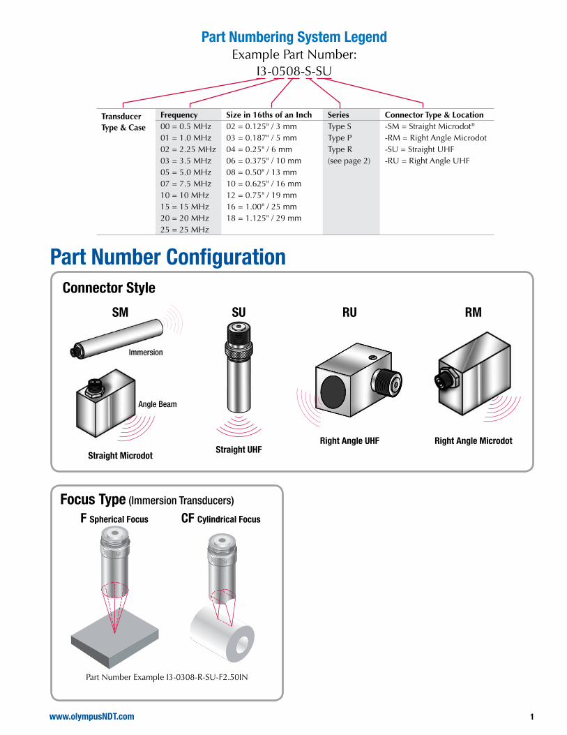
Part Number ConfigurationConnector Style
CF Cylindrical Focus
RU
Right Angle UHF
SU
Straight UHF
RM
Right Angle Microdot
SM
Straight Microdot
Immersion
Angle Beam
Transducer Type & Case
Frequency Size in 16ths of an Inch Series Connector Type & Location00 = 0.5 MHz 02 = 0.125" / 3 mm Type S -SM = Straight Microdot®
01 = 1.0 MHz 03 = 0.187" / 5 mm Type P -RM = Right Angle Microdot02 = 2.25 MHz 04 = 0.25" / 6 mm Type R -SU = Straight UHF03 = 3.5 MHz 06 = 0.375" / 10 mm (see page 2) -RU = Right Angle UHF05 = 5.0 MHz 08 = 0.50" / 13 mm07 = 7.5 MHz 10 = 0.625" / 16 mm10 = 10 MHz 12 = 0.75" / 19 mm15 = 15 MHz 16 = 1.00" / 25 mm20 = 20 MHz 18 = 1.125" / 29 mm25 = 25 MHz
Part Numbering System LegendExample Part Number:
I3-0508-S-SU
Focus Type (Immersion Transducers)
Part Number Example I3-0308-R-SU-F2.50IN

2
The transducer is one of the most critical components of any ultrasonic system. A great deal of attention should be paid to selecting the proper transducer for the application.
The performance of the system as a whole is of great importance. Variations in instrument characteristics and settings as well as material properties and coupling conditions play a major role in system performance.
We have developed three different series of transducers to respond to the need for variety. Each series has its own unique characteristics.
Transducer configuration also has an impact on system performance. Consideration should be given to the use of focused transducers, transducers with wear surfaces that are appropriate for the test material, and the choice of the appropriate frequency and element diameter.
The summaries below provide a general description of the performance characteristics of each transducer series. While these guidelines are quite useful, each application is unique and performance will be dependent on electronics, cabling, and transducer configuration, frequency, and element diameter.
Transducer Selection Criteria
Harisonic “P” type transducers are narrowband, lightly damped, tuned transducers. They have high-energy output and penetrating power, but have limited resolving power.
Harisonic “s” type transducers are mediumband, medium damped, tuned transducers. They are used for general purpose flaw detection, and represent a compromise between high sensitivity and high resolution.
Harisonic “r” type transducers are broadband, highly damped, tuned transducers. They are used for high resolution, near and far surface flaw detection, and thickness gaging applications.

3www.olympusNDT.com
Test and DocumentationAll Olympus NDT transducers undergo a strict testing regime before they are deemed acceptable for use in the field. All tests are done in accordance with the ASTM E1065 Standard Guide for Evaluating Characteristics of Ultrasonic Search Units. As part of the test and documentation process, all transducers will automatically be shipped with a Real Time Waveform Spectrum
(RTWFS) or Pulse Characterization and are given the option of further documentation at the time of order. In addition, optional flaw/resolution tests, axial beam profile and transverse beam profiles can also be done on certain types of transducers. Please consult us with any special testing requirements.
Transverse Beam ProfilesThe optional Transverse Beam Profiles are typically done on immersion transducers, and provide critical information on the transducer’s sound field. This test is performed at the measured focal length, along the X and Y axes. Beam width and symmetry are measured.
Axial (On-Axis) Beam ProfileThe optional Axial or On-Axis Beam Profile is typically done on immersion type transducers, and provides critical information about the transducer’s sound field. This test is performed with the transducer face starting close to the target and then moving away along the Z-axis. Pulse echo amplitude vs. distance, focal length, and depth of field are measured.
Flaw Resolution TestThe optional Flaw Resolution Test certifies the resolving power of Harisonic® transducers. This test is typically performed on immersion type transducers, with the target being specified by the customer. Near or far surface resolution can be measured.
Transducer Analysis Report (Pulse Characterization)The Transducer Pulse Characterization data sheet is our standard documentation, and is provided with every Harisonic® transducer, free of charge. The RF Waveform and Frequency Spectrum information is recorded and stored in our database, for future reference. Important parameters such as Peak and Center Frequency, Bandwidth, Pulse Voltage and Loop Gain are measured per ASTM E1065 guidelines.
-0.20 -0.15 -0.10 -0.05 0.00 0.05 0.10 0.15 0.20 in
0.0
0
.1
0.2
0
.3
0.4
0
.5
0.6
0
.7
Vol
ts
-0.20 -0.15 -0.10 -0.05 0.00 0.05 0.10 0.15 0.20 in
0.0
0
.1
0.2
0
.3
0.4
0
.5
0.6
0
.7
Vol
ts
Transducer Profile Report
Transverse Profiles at Focal Depth
Date of Test
Focal Spot Width Ratios
0.061 in0.043 in0.026 in0.018 in
-0.025 in -0.035 inHigh Side
Beam Width
Low Side
dBdBBeam width at
0.060 in0.041 in0.031 in0.021 in
-0.020 in -0.029 inHigh Side
Beam Width
Low Side
dBdBBeam Width at
-6.553
X Axis Cross Section Y Axis Cross Section
June 29, 2006 Tested by
@
Filename
August 28, 2006Report date
06F918-Beam-RF Ascan and Xsections.sdtChecked by
Notes
6363-0.080 in
0.153 in0.073 in
dB20
Date
Signed
0.151 in0.076 in
-0.075 in
dB20
3 dB dB6-3.278 @X/Y =X/Y =
Focal Length
10.0
UHFConnector TypeElement Dimensions
Case Style
mm 08ssalC
R-L
I3
Immersion
0.375
Tuning
Serial NumberPart Number
Company
06F918I3-1006- T
Nominal Frequency
Focal Type Spherical
3.115 Water Path
Purchase Spec. HLI
VV MHz
dBdBΩ
185Pulse Voltage
1
Input Range
340
Digitizer Pulse Energy
Attenuation 16
OUTH.P. Filter
evieceR resluPerawtfoS r
GainCompuScope 12100M
Winspect
40
Panametrics 5052UA
Pulse Damping
Cable Target Serial No. a/n:tegraT 0.250 in. dia. Steel BallRG 58/AU
Test Configuration - Profile Scans
+/- 1
Scope HP 54510B
-- ----
Transducer Analysis Report
Filename
Report Date
Date of Test Tested by
Signed
06F918-Beam-RF Ascan and Xsections.sdt
Notes
Focal Length
10.0
UHFConnector TypeElement Dimensions
Case Style
mm 08ssalC
R-L
I3
Immersion
0.375Tuning
Serial NumberPart Number
Company
06F918I3-1006- T
Bandwidth at
0 2 4 6 8 10 12 14 16 18 MHz
0.0
0.
1 0
.2
0.3
0.4
0.
5 0
.6
0.7
0.8
0.
9 1
.0
106.3 106.4 106.5 106.6 106.7 106.8 106.9 107.0 107.1 usec
-0.
8 -
0.6
-0.
4 -
0.2
0.0
0
.2
0.4
0
.6
0.094 usec
4.57 MHz 5.40 MHz
9.13 MHzPeak Frequency
dB
8.79 MHzCenter FrequencyWaveform Duration
0.132 usec
3.115
106.750 usec
dB
11.50 MHz
6.09 MHz
High Frequency
Low Frequency
Bandwidth
11.08 MHz
6.51 MHz
52.0 % 61.4 %% Bandwidth
Water Path
dB
dB 0.170 usec
June 29, 2006
August 28, 2006
Nominal Frequency
Focal Type Spherical
Peak Amplitude 1.307 @
dB2 3
1063
Checked by
5.26 MHz
dB6
12.45 MHz
7.19 MHz
81.2 %
8.79 MHz 8.86 MHz
Purchase Spec. HLI
Pulse Voltage
Loop GainRec. Signal
VV MHz
dB
dBΩ
185Pulse Voltage
1
Input Range
340
Digitizer Pulse Energy
Attenuation 16
OUTH.P. Filter
evieceR resluPerawtfoS r
GainCompuScope 12100M
Winspect
40
Panametrics 5052UA
Pulse Damping
Cable: n/a0.250 in. dia. Steel Ball
Test Configuration - Pulse Capture
+/- 1
Scope HP 54510B
Loop Gain
Date
.oN laireS tegraTtegraTUA/85 GR
185V0.125
-63.405 dB
V
- --
---
Flaw Resolution Report
3.08 3.10 3.12 3.14 3.16 3.18 -10
0 -
80
-60
-
40
-20
0
2
0 4
0 6
0 8
0 1
00
%
Report Date
Date of Test Tested by
Signed
June 29, 2006
August 28, 2006
Date
Checked by
Notes
06F918-Beam-RF Ascan and Xsections.sdtFilename
Focal Length
10.0
UHFConnector TypeElement Dimensions
Case Style
mm 08ssalC
R-L
I3
Immersion
0.375
Tuning
Serial NumberPart Number
Company
06F918I3-1006- T
Nominal Frequency
Focal Type Spherical
Purchase Spec. HLI
Logged Interface Signal
Displayed Flaw
Calculated @T/R
Relative SensitivitySeparation
Signal to Noise
Working RangeVpp
dB
BdV
uSV
in.
0.970
20
0.6230.0270
0.270
VV MHz
dB
dBΩ
185Pulse Voltage
1
Input Range
340
Digitizer Energy
Attenuation 18
OUTH.P. Filter
esluPerawtfoS r
GainCompuScope 12100M
Winspect
40
Panametrics 5052UA
Damping:
Cable: Target Serial 63410A:tegraT #2 FBH @ 0.075"RG 58/AU
Test Configuration - Flaw Resolution
+/- 1
Scope HP 54510B
340.220
3.115 Water Path Dispay Water Path
Transducer Profile Report
Sound Field Axial Profile - Z Axis
Date of Test
4.064 in2.508 in
Far Distance2.276 in4.768 in
Depth of Field
Near Distance
2.492 in1.557 in
Depth of Field atFocal Distance 3.115 in
2.0 2.5 3.0 3.5 4.0 4.5 5.0 in
0
10
20
30
40
50
60
70
%
June 29, 2006 Tested by
Filename
August 28, 2006Report date
06F918-Beam-RF Ascan and Xsections.sdt Checked by
Notes
6 Bd3 01Bd dB2.046 in
3.453 in5.499 in
Date
Signed
Focal Length
10.0
UHFConnector TypeElement Dimensions
Case Stylemm 08ssalC
R-L
I3Immersion
0.375Tuning
Serial NumberPart Number
Company
06F918I3-1006- T
Nominal Frequency
Focal Type Spherical
Purchase Spec HLI
VV MHz
dB
dBΩ
185Pulse Voltage
1
Input Range
340
Digitizer Pulse Energy
Attenuation 16
OUTH.P. Filter
evieceR resluPerawtfoS r
GainCompuScope 12100M
Winspect
40
Panametrics 5052UA
Pulse Damping
a/ntegraTelbaC 0.250 in. dia. Steel BallRG 58/AU
Test Configuration - Profile Scans
+/- 1
Scope HP 54510B
Target Serial No.
- - -

4
Immersion Transducers Immersion transducers are specifically designed to test parts partially or wholly immersed in water, which allows a uniform and fast coupling technique for rapid scanning of parts. Focusing lens can be added to increase transducer sensitivity and performance in a particular area of a part. Immersion transducers can be focused either spherically or cylindrically upon request within the allowable focal range for a given frequency and element size.
i-1 and i-2 Style Housings 0.25 inches (6 mm) diameter elements with 0.375 inches (10 mm) housings for difficult to reach fillet or bore areas are available with straight Microdot (I-1) or straight UHF (I-2) connectors and 303 stainless steel housings.
Type S-Standard General Purpose
Type R-High Resolution
Focus(inches)
Frequency (MHz)
Element Dia. (in) (mm)
Part Number
Part Number Min. Max.
Type I-1
2.25 0.25 6 i1-0204-S-SM i1-0204-R-SM 0.35 0.45
3.50 0.25 6 i1-0304-S-SM i1-0304-R-SM 0.39 0.70
5.0 0.25 6 i1-0504-S-SM i1-0504-R-SM 0.43 1.00
10 0.25 6 i1-1004-S-SM i1-1004-R-SM 0.46 2.10
15 0.25 6 i1-1504-S-SM i1-1504-R-SM 0.50 3.15
20 0.25 6 i1-2004-S-SM i1-2004-R-SM 0.50 4.20
25 0.25 6 i1-2504-S-SM i1-2504-R-SM 0.50 5.25
Type I-2
2.25 0.25 6 i2-0204-S-SU i2-0204-R-SU 0.35 0.45
3.5 0.25 6 i2-0304-S-SU i2-0304-R-SU 0.39 0.70
5.0 0.25 6 i2-0504-S-SU i2-0504-R-SU 0.43 1.00
10 0.25 6 i2-1004-S-SU i2-1004-R-SU 0.46 2.10
15 0.25 6 i2-1504-S-SU i2-1504-R-SU 0.50 3.15
20 0.25 6 i2-2004-S-SU i2-2004-R-SU 0.50 4.20
25 0.25 6 i2-2504-S-SU i2-2504-R-SU 0.50 5.25
2.0 in.
.375 in.i-1 Dimensions
2.0 in.
2.6 in.
.375 in.
i-2 Dimensions
Unfocused Focused
5www.olympusNDT.com
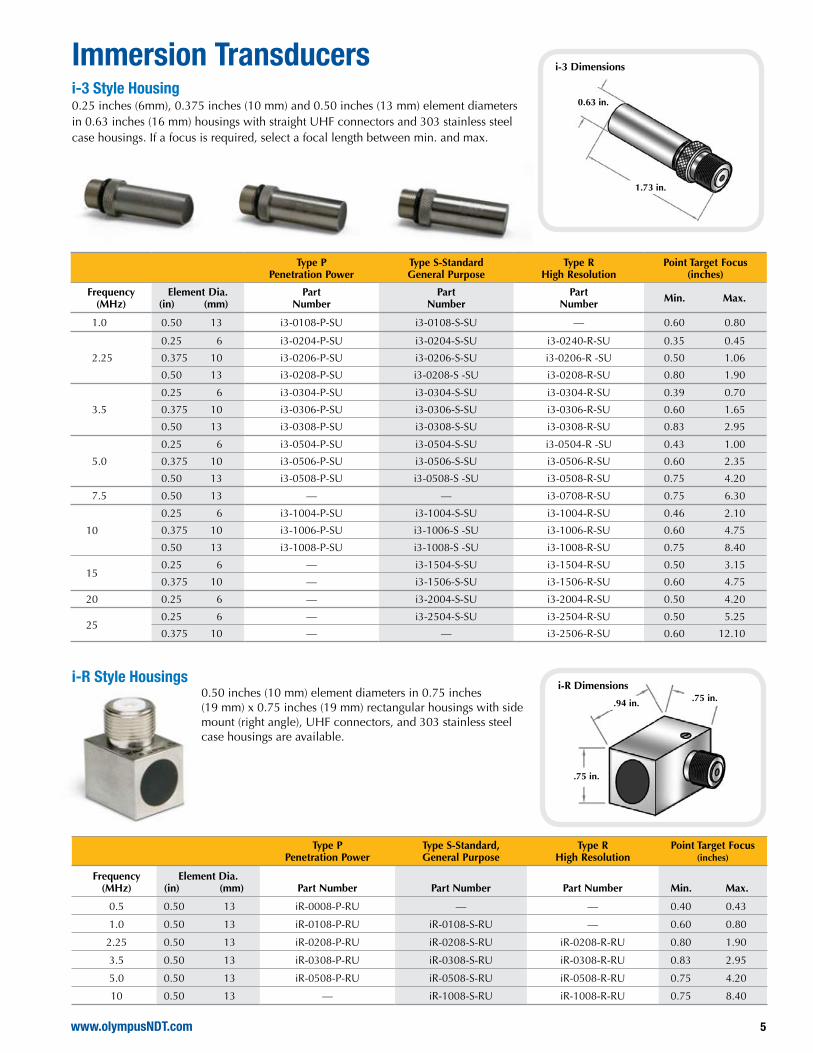
Immersion Transducersi-3 Style Housing0.25 inches (6mm), 0.375 inches (10 mm) and 0.50 inches (13 mm) element diameters in 0.63 inches (16 mm) housings with straight UHF connectors and 303 stainless steel case housings. If a focus is required, select a focal length between min. and max.
Type P Penetration Power
Type S-Standard General Purpose
Type R High Resolution
Point Target Focus(inches)
Frequency (MHz)
Element Dia. (in) (mm)
Part Number
Part Number
Part Number Min. Max.
1.0 0.50 13 i3-0108-P-SU i3-0108-S-SU — 0.60 0.80
2.25
0.25 6 i3-0204-P-SU i3-0204-S-SU i3-0240-R-SU 0.35 0.45
0.375 10 i3-0206-P-SU i3-0206-S-SU i3-0206-R -SU 0.50 1.06
0.50 13 i3-0208-P-SU i3-0208-S -SU i3-0208-R-SU 0.80 1.90
3.5
0.25 6 i3-0304-P-SU i3-0304-S-SU i3-0304-R-SU 0.39 0.70
0.375 10 i3-0306-P-SU i3-0306-S-SU i3-0306-R-SU 0.60 1.65
0.50 13 i3-0308-P-SU i3-0308-S-SU i3-0308-R-SU 0.83 2.95
5.0
0.25 6 i3-0504-P-SU i3-0504-S-SU i3-0504-R -SU 0.43 1.00
0.375 10 i3-0506-P-SU i3-0506-S-SU i3-0506-R-SU 0.60 2.35
0.50 13 i3-0508-P-SU i3-0508-S -SU i3-0508-R-SU 0.75 4.20
7.5 0.50 13 — — i3-0708-R-SU 0.75 6.30
10
0.25 6 i3-1004-P-SU i3-1004-S-SU i3-1004-R-SU 0.46 2.10
0.375 10 i3-1006-P-SU i3-1006-S -SU i3-1006-R-SU 0.60 4.75
0.50 13 i3-1008-P-SU i3-1008-S -SU i3-1008-R-SU 0.75 8.40
150.25 6 — i3-1504-S-SU i3-1504-R-SU 0.50 3.15
0.375 10 — i3-1506-S-SU i3-1506-R-SU 0.60 4.75
20 0.25 6 — i3-2004-S-SU i3-2004-R-SU 0.50 4.20
250.25 6 — i3-2504-S-SU i3-2504-R-SU 0.50 5.25
0.375 10 — — i3-2506-R-SU 0.60 12.10
0.63 in.
1.73 in.
i-3 Dimensions
i-R Style Housings0.50 inches (10 mm) element diameters in 0.75 inches (19 mm) x 0.75 inches (19 mm) rectangular housings with side mount (right angle), UHF connectors, and 303 stainless steel case housings are available.
.75 in..94 in.
.75 in.
Type P Penetration Power
Type S-Standard, General Purpose
Type RHigh Resolution
Point Target Focus (inches)
Frequency (MHz)
Element Dia.(in) (mm) Part Number Part Number Part Number Min. Max.
0.5 0.50 13 iR-0008-P-RU — — 0.40 0.43
1.0 0.50 13 iR-0108-P-RU iR-0108-S-RU — 0.60 0.80
2.25 0.50 13 iR-0208-P-RU iR-0208-S-RU iR-0208-R-RU 0.80 1.90
3.5 0.50 13 iR-0308-P-RU iR-0308-S-RU iR-0308-R-RU 0.83 2.95
5.0 0.50 13 iR-0508-P-RU iR-0508-S-RU iR-0508-R-RU 0.75 4.20
10 0.50 13 — iR-1008-S-RU iR-1008-R-RU 0.75 8.40
i-R Dimensions

6
Immersion Transducers i-4, i-7 and i-8 Style HousingsVarious element and case sizes with straight UHF connectors and 303 stainless steel case housings are available.
Type P Penetration Power
Type S-Standard, General Purpose
Type R High Resolution
Focus (inches)
Frequency(MHz)
Element Dia(in) (mm) Part Number Part Number Part Number Min. Max.
0.50
0.75 19 i7-0012-P-SU — — 1.50 2.10
1.00 25 i8-0016-P-SU i8-0016-S-SU — 1.25 1.65
1.125 29 i8-0018-P-SU i8-0018-S-SU — 0.78 0.93
1.0
0.50 13 i4-0108-P-SU i4-0108-S-SU i4-0108-R-SU 0.60 0.80
0.625 16 i4-0110-P-SU i4-0110-S-SU i4-0110-R-SU 0.70 1.34
0.75 19 i7-0112-P-SU i7-0112-S-SU i7-0112-R-SU 1.00 1.90
1.00 25 i8-0116-P-SU i8-0116-S-SU i8-0116-R-SU 1.63 3.38
1.125 29 i8-0118-P-SU i8-0118-S-SU i8-0118-R-SU 1.90 4.30
2.25
0.375 10 i4-0206-P-SU i4-0206-S-SU i4-0206-R-SU 0.55 1.00
0.50 13 i4-0208-P-SU i4-0208-S-SU i4-0208-R-SU 0.80 1.90
0.625 16 i4-0210-P-SU i4-0210-S-SU i4-0210-R-SU 0.90 3.00
0.75 19 i7-0212-P-SU i7-0212-S-SU i7-0212-R-SU 1.00 4.30
1.00 25 i8-0216-P-SU i8-0216-S-SU i8-0216-R-SU 1.88 7.60
1.125 29 i8-0218-P-SU i8-0218-S-SU i8-0218-R-SU 2.15 9.50
3.5
0.375 10 i4-0306-P-SU i4-0306-S-SU i4-0306-R-SU 0.60 1.60
0.50 13 i4-0308-P-SU i4-0308-S-SU i4-0308-R-SU 0.83 3.00
0.625 16 i4-0310-P-SU i4-0310-S-SU i4-0310-R-SU 0.90 4.70
0.75 19 i7-0312-P-SU i7-0312-S-SU i7-0312-R-SU 1.00 6.65
1.00 25 — i8-0316-S-SU — 1.95 11.25
1.125 29 — i8-0318-S-SU — 2.20 15.30
5.0
0.375 10 i4-0506-P-SU i4-0506-S-SU i4-0506-R-SU 0.55 2.40
0.50 13 i4-0508-P-SU i4-0508-S-SU i4-0508-R-SU 0.60 4.30
0.625 16 i4-0510-P-SU i4-0510-S-SU i4-0510-R-SU 0.68 6.73
0.75 19 i7-0512-P-SU i7-0512-S-SU i7-0512-R-SU 1.00 2.0
1.00 25 i8-0516-P-SU i8-0516-S-SU i8-0516-R-SU 1.95 14.40
1.125 29 i8-0518-P-SU i8-0518-S-SU i8-0518-R-SU 2.40 21.80
7.5
0.375 10 — i4-0306-S-SU — 0.60 1.60
0.50 13 — i4-0308-S-SU — 0.83 3.00
0.625 16 — i4-0310-S-SU — 0.90 4.70
10
0.375 10 — i4-1006-S-SU i4-1006-R-SU 0.60 4.75
0.50 13 — i4-1008-S-SU i4-1008-R-SU 0.75 8.40
0.625 16 — i4-1010-S-SU i4-1010-R-SU 0.85 13.40
0.75 19 i4-1012-P-SU i4-1012-S-SU i4-1012-R-SU 1.00 15.37
150.375 10 i4-1506-S-SU i4-1506-R-SU 0.60 7.10
0.50 13 i4-1508-S-SU i4-1508-R-SU 0.75 11.75
20 0.375 10 — i4-2006-S-SU i4-2006-R-SU 0.55 9.60
Styles i-4, i-7, and i-8
Element Dia. (in) A B
0.75 1.00 1.375
0.50, 0.625 0.748 1.375
1.00, 1.125 1.25 1.375

8
Size Frequency(MHz) Material Connector Angle
XX = Specify Angle
0.120" x 0.250"3 mm x 6 mm
2.25 Aluminum Straight HS-225-2-XX-AL-SM
2.25 Aluminum Right Angle HS-225-2-XX-AL-RM
2.25 Steel Straight HS-225-2-XX-ST-SM
2.25 Steel Right Angle HS-225-2-XX-ST-RM
5.0 Aluminum Straight HS-225-5-XX-AL-SM
5.0 Aluminum Right Angle HS-225-5-XX-AL-RM
5.0 Steel Straight HS-225-5-XX-ST-SM
5.0 Steel Right Angle HS-225-5-XX-ST-RM
10 Aluminum Straight HS-225-10-XX-AL-SM
10 Aluminum Right Angle HS-225-10-XX-AL-RM
10 Steel Straight HS-225-10-XX-ST-SM
10 Steel Right Angle HS-225-10-XX-ST-RM
0.187" x 0.187"5 mm x 5 mm
2.25 Aluminum Straight HS-877-2-XX-AL-SM
2.25 Aluminum Right Angle HS-877-2-XX-AL-RM
2.25 Steel Straight HS-877-2-XX-ST-SM
2.25 Steel Right Angle HS-877-2-XX-ST-RM
5.0 Aluminum Straight HS-877-5-XX-AL-SM
5.0 Aluminum Right Angle HS-877-5-XX-AL-RM
5.0 Steel Straight HS-877-5-XX-ST-SM
5.0 Steel Right Angle HS-877-5-XX-ST-RM
10 Aluminum Straight HS-877-10-XX-AL-SM
10 Aluminum Right Angle HS-877-10-XX-AL-RM
10 Steel Straight HS-877-10-XX-ST-SM
10 Steel Right Angle HS-877-10-XX-ST-RM
Specify material to be inspected.
Sub-Miniature and Ultra-Miniature Angle Beam TransducersThe sub-miniature (HS-225) and ultra-miniature (HS-877) angle beam transducers are supplied in frequencies from 2.25 to 10.0 MHz with angles from 45° through 90°. Epoxy housings prevent the transducer from causing scratches to the test surface. These transducers are ideal for inspection of small diameter welded tubes and applications where the requirement is for a shear-wave transducer with a very small footprint. Depending on the type selected, either top or side mounted, Microdot connectors are available. When ordering, please specify part number, frequency, angle, material to be inspected, and connector location.
Transducer Housing Dimensions
Sub-Miniature: 0.375 in. L x 0.425 in. H x .0325 in. W
Ultra-Miniature: 0.375 in. L x 0.375 in. H x 0.250 in. W

9www.olympusNDT.com
Integral Angle Beam TransducersMiniature potted angle beam transducers provide an excellent balance between size and performance by utilizing integral angle beam shear wave wedges. Overall size and footprint are reduced compared to a screw-in style transducer and wedge with little or no sacrifice in performance. Epoxy housings prevent test surface scratching caused by the transducer.
Connectors are available in either top (straight) or side (right angle) mount depending on application requirements. Four standard shear wave angles of 45°, 60°, 70°, and 90° or custom angles are available upon request.
Size Frequency(MHz) Material Connector Angle
XX = Angle 45, 60, 70 or 90
0.187" x 0.187"5 mm x 5 mm
2.25 Aluminum Straight PAB-0203-XX-AL-SM
2.25 Aluminum Right Angle PAB-0203-XX-AL-RM
2.25 Steel Straight PAB-0203-XX-ST-SM
2.25 Steel Right Angle PAB-0203-XX-ST-RM
5.0 Aluminum Straight PAB-0503-XX-AL-SM
5.0 Aluminum Right Angle PAB-0503-XX-AL-RM
5.0 Steel Straight PAB-0503-XX-ST-SM
5.0 Steel Right Angle PAB-0503-XX-ST-RM
10 Aluminum Straight PAB-1003-XX-AL-SM
10 Aluminum Right Angle PAB-1003-XX-AL-RM
10 Steel Straight PAB-1003-XX-ST-SM
10 Steel Right Angle PAB-1003-XX-ST-RM
0.250" x 0.250"6 mm x 6 mm
2.25 Aluminum Straight PAB-0204-XX-AL-SM
2.25 Aluminum Right Angle PAB-0204-XX-AL-RM
2.25 Steel Straight PAB-0204-XX-ST-SM
2.25 Steel Right Angle PAB-0204-XX-ST-RM
5.0 Aluminum Straight PAB-0504-XX-AL-SM
5.0 Aluminum Right Angle PAB-0504-XX-AL-RM
5.0 Steel Straight PAB-0504-XX-ST-SM
5.0 Steel Right Angle PAB-0504-XX-ST-RM
10 Aluminum Straight PAB-1004-XX-AL-SM
10 Aluminum Right Angle PAB-1004-XX-AL-RM
10 Steel Straight PAB-1004-XX-ST-SM
10 Steel Right Angle PAB-1004-XX-ST-RM
0.30"
0.30"
0.55"
0.55"
0.675"
0.675"
10
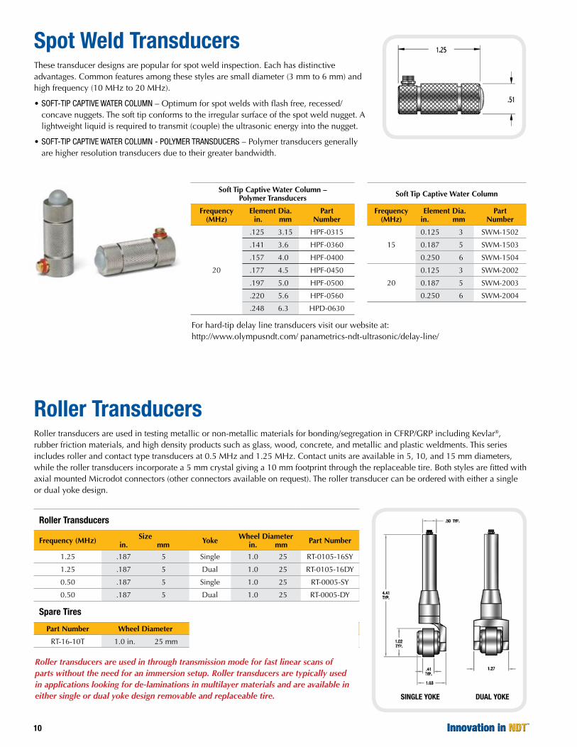
Spot Weld TransducersThese transducer designs are popular for spot weld inspection. Each has distinctive advantages. Common features among these styles are small diameter (3 mm to 6 mm) and high frequency (10 MHz to 20 MHz).
• soft-tiP caPtive Water column – Optimum for spot welds with flash free, recessed/concave nuggets. The soft tip conforms to the irregular surface of the spot weld nugget. A lightweight liquid is required to transmit (couple) the ultrasonic energy into the nugget.
• soft-tiP caPtive Water column - Polymer transducers – Polymer transducers generally are higher resolution transducers due to their greater bandwidth.
Soft Tip Captive Water Column – Polymer Transducers
Frequency (MHz)
Element Dia. in. mm
Part Number
20
.125 3.15 HPF-0315
.141 3.6 HPF-0360
.157 4.0 HPF-0400
.177 4.5 HPF-0450
.197 5.0 HPF-0500
.220 5.6 HPF-0560
.248 6.3 HPD-0630
Soft Tip Captive Water Column
Frequency (MHz)
Element Dia. in. mm
Part Number
15
0.125 3 SWM-1502
0.187 5 SWM-1503
0.250 6 SWM-1504
20
0.125 3 SWM-2002
0.187 5 SWM-2003
0.250 6 SWM-2004
Roller TransducersRoller transducers are used in testing metallic or non-metallic materials for bonding/segregation in CFRP/GRP including Kevlar®, rubber friction materials, and high density products such as glass, wood, concrete, and metallic and plastic weldments. This series includes roller and contact type transducers at 0.5 MHz and 1.25 MHz. Contact units are available in 5, 10, and 15 mm diameters, while the roller transducers incorporate a 5 mm crystal giving a 10 mm footprint through the replaceable tire. Both styles are fitted with axial mounted Microdot connectors (other connectors available on request). The roller transducer can be ordered with either a single or dual yoke design.
Roller Transducers
Frequency (MHz) Size in. mm Yoke Wheel Diameter
in. mm Part Number
1.25 .187 5 Single 1.0 25 RT-0105-16SY
1.25 .187 5 Dual 1.0 25 RT-0105-16DY
0.50 .187 5 Single 1.0 25 RT-0005-SY
0.50 .187 5 Dual 1.0 25 RT-0005-DY
Spare Tires
Part Number Wheel Diameter
RT-16-10T 1.0 in. 25 mm
Roller transducers are used in through transmission mode for fast linear scans of parts without the need for an immersion setup. Roller transducers are typically used in applications looking for de-laminations in multilayer materials and are available in either single or dual yoke design removable and replaceable tire. SINGLE YOKE DUAL YOKE
For hard-tip delay line transducers visit our website at: http://www.olympusndt.com/ panametrics-ndt-ultrasonic/delay-line/

11www.olympusNDT.com
Pencil Transducers These high frequency, focused delay line transducers are compatible with any ultrasonic instrument capable of displaying a return echo at depths as low as .010 inches in steel. The typical range is approximately from .010 inches to 0.250 inches in steel. The 0.060 inches circular contact face enables readings to be taken on curved surfaces. Typical applications for these transducers include the inspection of turbine blades, small diameter tubing and concave areas in small parts. Both transducers utilize replaceable delay tips. For best performance, a short cable (such as MB type, 6’) should be used. These models, indicated by a part number ending with an “L”, incorporate PowerLink™ Technology to assure optimal performance when used with a Sonic ultrasonic instrument.
The HC-876 ultrasonic transducer operates at high frequency (20 MHz) with a broad bandwidth and small contact surface. Its chief application is thickness measuring of critical components such as jet engine blades. It is fitted with a Microdot connector.
Replaceable Delay Line
Frequency(MHz)
Nominal Element Size
in. mm
Part Number
Straight Handle
Right Angle Handle
10 0.125 3 HC-398-RDL HC-398-RA-RDL
Replacement Tips (10 ms) HAX-398 HAX-398
Permanent Delay Line
Frequency(MHz)
Nominal Element Size
in. mm
Part Number
Straight Handle
Right Angle Handle
20 0.125 3 HC-876-L HC-876*, HC-876-RA-L
Permanent Tip Delay (10 ms) *Not PowerLink compatible.
.06 in.
.33 in.
.38 in.4.07 in.
HC-398-RDL Straight Pencil Type
.70 in.
.06 in..33 in.
.38"
4.30 in.
HC-398-RA-RDL Right Angle Type
.70 in.
.06 in..12 in.
.38"
4.30 in.
HC-876-RA-L Right Angle Type
.12 in.
.06 in..38 in.
4.07 in.
HC-876-L Straight Pencil Type
.25 in.
.12 in..06 in.
.375 in.
5.70 in.
HC-876 Right Angle Type
HC-876-RA-L Right Angle Type
HC-398-RDL Straight Pencil Type

13www.olympusNDT.com
Near Field Distances of Flat Transducers in WaterThe near field values in this table have been determined using the following equation:
The minimum and maximum practical focal lengths have been calculated by considering the acoustic and mechanical limitations of each configuration. These limitations are a function of transducer frequency, element diameter, and case dimensions. There may be exceptions to the limits listed in the table.
Technical NotesTable 2
Near Field Distance of Flat Transducers in Water
FrequencyElement Diameter
NFocal Length (PTF)**Min Max
(MHz) (inches) (inches) (inches) (inches)
0.5
10.500 4.757 2.15 3.80
1.125 2.661 10.500 2.10
1.00 2.095 1.25 1.65
0.75 1.164 0.78 0.93
1.0
10.500 9.559 20.500 7.65
1.125 5.366 1.90 4.30
1.00 4.235 10.625 3.38
0.75 2.372 1.00 1.90
00.500 1.043 0.60 0.80
2.25
10.500 21.534 2.70 140.500
1.125 12.099 2.15 90.500
1.00 9.554 1.875 7.60
0.75 5.364 1.00 4.30
00.500 2.374 0.80 1.90
00.375 1.329 00.500 1.06
0.25 0.584 0.35 0.45
3.5
1.00 14.868 1.95 11.5
0.75 8.350 1.00 6.65
00.500 3.699 0.83 2.95
00.375 2.073 0.60 1.65
0.25 0.914 0.385 0.70
5.0
1.00 21.243 1.95 14.40‡
0.75 11.932 1.00 90.500
00.500 5.287 0.75 4.20
00.375 2.965 0.60 2.35
0.25 1.309 0.43 1.00
7.50.75 17.900 1.00 12.75‡
00.500 7.933 0.75 6.30‡
10
1.00 42.490 2.00 20.00‡
0.75 23.868 1.00 150.375‡
00.500 10.579 0.75 8.40‡
00.375 5.934 0.60 4.75‡
0.25 2.622 0.46 2.10
15
00.500 15.870 0.75 11.75‡
00.375 8.902 0.60 7.10‡
0.25 3.935 00.500 3.15‡
200.25 5.247 00.500 4.20‡
0.125 1.290 0.25 1.00‡
25 0.25 6.559 00.500 5.25‡
** Panametrics’ Standard Case style, Large Diameter Case style, Slim Line Case style, and Pencil Case style immersion transducers with straight connectors can be focused between the minimum and maximum point target focal (PTF) distance limits listed above. Please consult Panametrics before ordering a transducer focused outside these limits.
‡ Consideration should be given to attenuation effects, which increase linearity with the square of frequency and the square of bandwidth. In applications where long water paths are required the effects of frequency dependent attenuation should be checked per ASTME 1065, Annex A7. It is advisable to consider the effects of frequency dependent attenuation if the focal distance equals or exceeds the following values:
Frequency Focal Length
MHz inches
5.0 13
7.5 6
10 3.5
15 1.5
20 0.8
25 0.5
30 0.4
Table 1Acoustic Properties of Materials
MaterialLongitudinal
VelocityShear
VelocityAcoustic
Impedance(in/ms)* (m/s) (in/ms)* (m/s) (Kg/m2s x 106)
Acrylic resin (Perspex®) 0.107 2,730 0.056 1,430 3.22
Aluminum 0.249 6,320 0.123 3,130 17.06
Beryllium 00.5008 12,900 0.350 8,880 23.5
Brass, naval 0.174 4,430 0.083 2,120 37.30
Cadmium 0.109 2,780 0.059 1,500 24.02
Columbium 0.194 4,920 0.083 2,100 42.16
Copper 0.183 4,660 0.089 2,260 41.61
Glycerine 0.076 1,920 — — 2.42
Gold 0.128 3,240 0.047 1,200 62.60
Inconel® 0.29 5,820 0.119 3,020 49.47
Iron 0.232 5,900 0.127 3,230 45.43
Iron, cast
(slow) 0.138 3,500 0.087 2,200 25.00
(fast) 0.220 5,600 0.126 3,220 40.00
Lead 0.085 2,160 0.028 700 24.49
Manganese 0.183 4,660 0.093 2,350 34.44
Mercury 0.057 1,450 — — 19.66
Molybdenum 0.246 6,250 0.132 3,350 63.75
Motor Oil (SAE 20 or 30) 0.069 1,740 — — 1.51
Nickel, pure 0.222 5,630 0.117 2,960 49.99
Platinum 0.156 3,960 0.066 1,670 84.74
Polyamide, (nylon, Perlon®)
(slow) 0.087 2,200 0.043 1,100 .40
(fast) 0.102 2,600 0.047 1,200 3.10
Polystyrene 0.092 2,340 — — 2.47
Polyvinylchloride, PVC, hard 0.094 2,395 0.042 1,060 3.35
Silver 0.142 3,600 0.063 1,590 37.76
Steel, 1020 0.232 5,890 0.128 3,240 45.63
Steel, 4340 0.230 5,850 0.128 3,240 45.63
Steel, 302 0.223 5,660 0.123 3,120 45.45
Austenitic stainless steel, 347 0.226 5,740 0.122 3,090 45.40
Austenitic stainless tin 0.131 3,320 0.066 1,670 24.20
Titanium, Ti 150A 0.240 6,100 0.123 3,120 27.69
Tungsten 0.204 5,180 0.113 2,870 99.72
Uranium 0.133 3,370 0.078 1,980 63.02
Water (20°C) 0.058 1,480 — — 1.48
Zinc 0.164 4,170 0.095 2,410 29.61
Zirconium 0.183 4,650 0.089 2,250 30.13
* Conversion Factor: 1 m/s = 3.937 x 10 -5 in/μ SSource: Nondestructive Testing Handbook, 2nd Edition, Volume 7Ultrasonic Testing ASNT, 1991, ed. Paul McIntire

www.olympusNDT.com
Copyright © 2008 by Olympus NDT.All specifications are subject to change without notice. All brands are trademarks or registered trademarks of their respective owners.
Olympus NDT48 Woerd Avenue • Waltham, MA 02453 • USA Tel.: (1) 781-419-3900 • Fax: (1) 781-419-398012569 Gulf Freeway • Houston, TX 77034 • USA Tel.: (1) 281-922-9300 • Fax: (1) 952-487-8877
Olympus NDT uK lTD.12 Nightingale Close • Rotherham, South Yorkshire S60 2AB • UK
Olympus siNgapOre pTe. lTD.491B River Valley Road 12-01/04, Valley Point Office Tower, 248373 • Singapore
Olympus ausTralia pTy. lTD.PO Box 985 • Mount Waverley, VIC 3149 • Australia