Embed Size (px)
Citation preview

6TH INTERNATIONAL CONFERENCE ON ELECTROMECHANICAL AND POWER SYSTEMS
October 4-6, 2007 - Chişinău, Rep.Moldova
68
HARDWARE/SOFTWARE STRUCTURE FOR THE CONTACT RESISTANCE ESTIMATION IN THE CASE OF
AN ELEMENTARY CONTACT
Cătălin PANCU, Adrian BARABOI, Maricel ADAM
Faculty of Electrical Engineering, “Gh. Asachi” Technical University of Iasi, 51-53, Bd. D. Mangeron, Iaşi, Romania, E-mail: [email protected]
Abstract − The paper proposes a hardware/software structure, based on the RISC (Reduced Instructions Set Computer) microcontrollers for the contact resistance estimation in the case of an elementary contact. Through this approach, is possible to local display of the monitored parameters and their transmission at a PC for an ulterior processing.
Keywords: hardware/software structure, contact resistance, elementary contact.
1. INTRODUCTION
The electric contacts have an important role in the manufacturing and behaviour of the electrical equipment. These are the elements of the current ways, constituted from tow metallic pieces, through their reaching obtaining the electrical conduction, [1]. The reaching of the contact pieces it realises under the force Fc action, of the pressing in contact, made using the mechanic devices, Fig. 1. Because the electric contacts represents the portions of the current ways, which support stresses of high intensities, is necessary that these elements to be characterised through a high reliability, resistance corresponding to stresses of different natures (mechanical, electrical, environmental factors), and also through a high thermal and electro-dynamic stability, [2]. The presents of an electric contact on a current way put, always, in evidence a supplementary electric resistance Rc, named contact resistance.
Fc
i1
22b 2a2a
2�2� 2�
Figure 1: The microscopic aspect of an electric contact
It consists that the strangle resistance Rs, as a first component of the contact resistance, is a result of the
discontinue transversal section of the current ways form the contact zone, fact which bring out the strangle of the current lines. The second component of the contact resistance, layer resistance, Rp, is the effect of the forming of some disturbing layers, usually with semiconductor proprieties, on the surfaces of the contact pieces. The calculus of the contacts realised from pieces with simple macrogeometry, at which the material state corresponding to the elastic deformations, it can do on the base of the Hertz theory. Indifferent of the surface contacts rugosity, their reaching can have place only into a finite number of points (Fig.1), real surface Ac,considered as a sum of the contact microsurfaces, always resulting less than apparent contact surface Ab, depending on the geometrical dimensions of the contact pieces.
2. RISC MICROCONTROLLER ARCHITECTURE
The RISC microcontroller is a powerful tool that provides a highly flexible and cost-effective solutions to many embedded control applications, [3]. Fig. 2 shows the RISC microcontroller architecture. The fast-access Register File concept contains 32 x 8-bit general purpose working registers with a single clock cycle access time. This means that during one single clock cycle, one Arithmetic Logic Unit (ALU) operation is executed. Two operands are output from the Register File, the operation is executed, and the result is stored back in the Register File – in one clock cycle. The ALU supports arithmetic and logic operations between registers or between a constant and a register. Single register operations can also be executed in the ALU. After an arithmetic operation, the Status Register is updated to reflect information about the result of the operation. In addition to the register operation, the conventional Memory Addressing modes can be used on the Register File as well.. The RISC microcontroller uses a Harvard architecture concept – with separate memories and buses for program and data. The Program memory is executed with a two-stage pipeline.

69
Figure 2: RISC microcontroller architecture
While one instruction is being executed, the next instruction is pre-fetched from the Program memory. This concept enables instructions to be executed in every clock cycle. The Program flow is provided by conditional and unconditional jump and call instructions, able to directly address the whole address space. Most AVR instructions have a single 16-bit word format. Every Program memory address contains a 16- or 32-bit instruction. The Program memory is In-System Programmable Flash memory. Program Flash memory space is divided in two sections, the Boot program section and the Application program section. Both sections have dedicated Lock Bits for write and read/write
protection. The SPM instruction that writes into the Application Flash memory section must reside in the Boot program section. Most RISC microcontroller instructions have a single 16-bit word format. Every program memory address contains a 16- or 32-bit instruction. The ATmega8, used in our application, provides the following features: 8K bytes of In-System Programmable Flash with Read-While-Write capabilities, 512 bytes of EEPROM, 1K byte of SRAM, 23 general purpose I/O lines, 32 general purpose working registers, three flexible Timer/Counters with compare modes, internal and external interrupts, a serial programmable USART, a byte oriented Two-wire Serial Interface, a 6-channel
Analog Comparator
Analog to Digital
Converter
Watchdog Timer
16-bit Timer/Count
er
8-bit Timer/Count
Serial UART
SPI Unit
Data Bus 8-bit
128 x 8 Data
SRAM
Interrupt unit
20 I/O Lines
ALU
32 x 8 General Purpose Registers
Instruction Decoder
256 x 8 EEPROM
Status and Control
Program Counter
Dire
ctA
ddre
ssin
g
2K x 16 Program Memory
Instruction Register
Control Lines
Indi
rect
Add
ress
ing

70
ADC with 10-bit accuracy, a programmable Watchdog Timer with Internal Oscillator, an SPI serial port, and five software selectable power saving modes. The Idle mode stops the CPU while allowing the SRAM, Timer/Counters, SPI port, and interrupt system to continue functioning. The Power-down mode saves the register contents but freezes the Oscillator, disabling all other chip functions until the next Interrupt or Hardware Reset. In Power-save mode, the asynchronous timer continues to run, allowing the user to maintain a timer base while the rest of the device is sleeping. The ADC Noise Reduction mode stops the CPU and all I/O modules except asynchronous timer and ADC, to minimize switching noise during ADC conversions. In Standby mode, the crystal/resonator Oscillator is running while the rest of the device is sleeping. This allows very fast start-up combined with low-power consumption.
3. HARDWARE/SOFTWARE STRUCTURE
Hardware/software structure has been made around of an Atmel ATmega8 AVR microcontroller, under the shape of an integrate device, [4]. Fig 3 and Fig. 4 shows an exterior photo of the integrated device and the principle scheme of this hardware-software structure, respectively.
Figure 3: Integrated device
In additional to the microcontroller, the device includes and a LCD for local display of the monitored parameters, a RS232 serial interface for bidirectional communication with a PC and four push buttons for local selection of various functions by the user. In order to obtains an improved resolution of the measurements received from the sensors placed around the elementary contact, these have been
amplified using LM324N operational amplifiers, having a specific amplifying rate for each channel.
Figure 4: Principle scheme of the hardware/software structure
In EEPROM memory of the ATMega8 AVR microcontroller, from the hardware/software structure realized, can be stored different measurements and settings. For the serial communication with other periphericals, the ATMega8 AVR microcontroller includes a specialised circuit USART (Universal Synchronous and Asynchronous serial Receiver and
Hardware/software structure
Microcontroller
Elementary contact
Operational amplifiers
Analog to digital
converterALU
Saved values
EPROM Memory
User program
Flash Memory
LCD
Sensors
RS232 Interface
71
Transmitter). For the TTL/RS232 compatibility, the hardware/software structure is equipped with a specialised circuit, HIN202.
4. EXPERIMENTAL TESTS
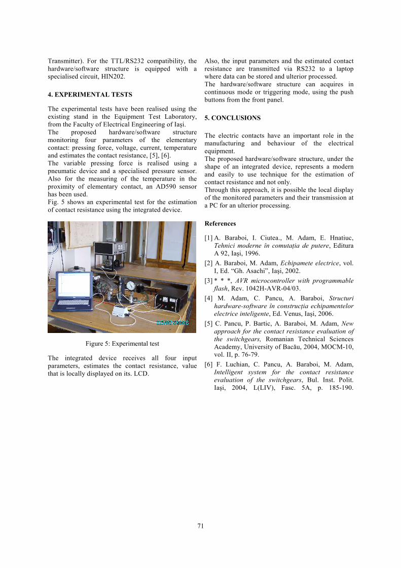
The experimental tests have been realised using the existing stand in the Equipment Test Laboratory, from the Faculty of Electrical Engineering of Iaşi. The proposed hardware/software structure monitoring four parameters of the elementary contact: pressing force, voltage, current, temperature and estimates the contact resistance, [5], [6]. The variable pressing force is realised using a pneumatic device and a specialised pressure sensor. Also for the measuring of the temperature in the proximity of elementary contact, an AD590 sensor has been used. Fig. 5 shows an experimental test for the estimation of contact resistance using the integrated device.
Figure 5: Experimental test
The integrated device receives all four input parameters, estimates the contact resistance, value that is locally displayed on its. LCD.
Also, the input parameters and the estimated contact resistance are transmitted via RS232 to a laptop where data can be stored and ulterior processed. The hardware/software structure can acquires in continuous mode or triggering mode, using the push buttons from the front panel.
5. CONCLUSIONS
The electric contacts have an important role in the manufacturing and behaviour of the electrical equipment. The proposed hardware/software structure, under the shape of an integrated device, represents a modern and easily to use technique for the estimation of contact resistance and not only. Through this approach, it is possible the local display of the monitored parameters and their transmission at a PC for an ulterior processing.
References
[1] A. Baraboi, I. Ciutea., M. Adam, E. Hnatiuc, Tehnici moderne în comutaţia de putere, Editura A 92, Iaşi, 1996.
[2] A. Baraboi, M. Adam, Echipamete electrice, vol. I, Ed. “Gh. Asachi”, Iaşi, 2002.
[3] * * *, AVR microcontroller with programmable flash, Rev. 1042H-AVR-04/03.
[4] M. Adam, C. Pancu, A. Baraboi, Structuri hardware-software în construcţia echipamentelor electrice inteligente, Ed. Venus, Iaşi, 2006.
[5] C. Pancu, P. Bartic, A. Baraboi, M. Adam, New approach for the contact resistance evaluation of the switchgears, Romanian Technical Sciences Academy, University of Bacău, 2004, MOCM-10, vol. II, p. 76-79.
[6] F. Luchian, C. Pancu, A. Baraboi, M. Adam, Intelligent system for the contact resistance evaluation of the switchgears, Bul. Inst. Polit. Iaşi, 2004, L(LIV), Fasc. 5A, p. 185-190.