Embed Size (px)
Citation preview

Hardware/Software Organization of a High Performance ATM HostInterface
C. Brendan S. Traw ([email protected])
Jonathan M. Smith ([email protected])
Distributed Systems Laboratory, University of Pennsylvania200 South 33rd St., Philadelphia, PA 19104-6389
ABSTRACT
Concurrent increases in network bandwidths and processor speeds have created a perfor-mance bottleneck at the workstation-to-network host interface . This is especially true for B-ISDN networks where the fixed length ATM cell is mismatched with application requirementsfor data transfer; a successful hardware/software architecture will resolve such differences andoffer high end-to-end performance.
The solution we report carefully splits protocol processing functions into hardware andsoftware implementations. The interface hardware is highly parallel and performs all per-cellfunctions with dedicated logic to maximize performance. Software provides support for thetransfer of data between the interface and application memory, as well as the state managementnecessary for virtual circuit setup and maintenance. In addition, all higher level protocol process-ing is implemented with host software.
The prototype connects an IBM RISC System/6000 to a SONET-based ATM network car-rying data at the OC-3c rate of 155 Mbps. An experimental evaluation of the interface hardwareand software has been performed. Several conclusions about this host interface architecture andthe workstations it is connected to are made.
1. Introduction
Generally, the goal of communications networks is to develop distributed applications. Such applications are depen-dent upon the performance of the communications subsystem, which includes the communications network,network/host interconnection, and the host itself. A new generation of networks with Gbps bandwidths are becom-ing available concurrently with very high performance workstations and bandwidth-hungry applications. Unfor-tunately, such workstations have been optimized for computational tasks. While their I/O architectures are adequatefor disk devices, 10 Mbps Ethernet connections, and more recently 100 Mbps FDDI, the very high bandwidthenvironment of B-ISDN poses significant challenges to the communications subsystem.
To properly analyze the problem, it is helpful to decompose the movement of data from application to appli-cation into a set of logical ‘‘layers’’ which communicate peer-to-peer. This functional decomposition can then beused to develop an architecture; the architecture is instantiated by a particular implementation in hardware andsoftware.
1.1. Host Interfaces and Protocol Architectures
Protocol architectures can be viewed as a stack of layers. The ISO OSI model, for example, consists of sevenlayers. When implemented, the protocol layers need not observe the separation of the logical model. The physicallayer must consist of hardware by definition, but the implementor can make hardware versus software implementa-tion decisions for each succeeding layer.
Software is often used when flexibility or tuning are required. As the behavior of a layer becomes better
Preprint - Will appear in Feb. 1993 IEEE J. Sel. Areas in Comm.

- 2 -
defined and understood, functionality can, in many cases, be migrated from software to hardware. The benefit istwofold. First, protocol processing overhead is offloaded from the host. This frees the host to address applicationsworkload, and provides concurrent processing for data communications functions. Second, the specializedhardware can often perform functions faster than the host, thus increasing the bandwidth available to applications.The difficulty is the determination of which functions should be migrated to hardware.
We have consistently chosen to implement the lower level, repetitive data movement and formatting functionsin hardware. Higher level protocol processing functions are implemented in host software.
1.2. Goals and Design Philosophy
The research goals are as follows:
(1) Developing a hardware/software architecture which provides the necessary performance, yet is sufficiently flex-ible to allow experimentation with portions of the protocol stack.
(2) Focusing on architectural solutions to achieve good cost/performance, so any results scale across technologychoices. This is particularly important in the context of the AURORA project, as the ultimate bandwidth goal isgreater than that attempted in this implementation.
(3) Not using on-board processors to both take advantage of host CPU improvements without redesigning the inter-face, and maintain low absolute cost.
The resulting host interface meets all three goals.
The design philosophy for our architecture is based on providing a ‘‘common denominator’’ set of services indedicated hardware. All per cell activities such as ATM header and adaptation layer creation and processing(including segmentation and reassembly) are performed by the host interface in hardware. The host is responsiblefor all higher level activities. We feel that this is reasonable since we are able to maintain flexibility for higher layerprotocol implementation in exchange for some overhead incurred by host software. Protocol flexibility is importantfor the following reasons:
� Not all protocols and applications are defined yet.� Services are extremely varied. It would be difficult, for example, to provide support for all possible protocol
stacks in hardware.
The host interface work at Penn has been centered on developing a high-performance host interface for IBM RISCSystem/6000 workstation hosts in the AURORA Gigabit Testbed environment [9]. Our host interface [27] is intendedfor the Sunshine-ATM logical topology. ATM provides particular challenges to the host interface architect due tothe small (53 byte) fixed cell size; this is at odds with the variable-size packet traffic generated by most computercommunications applications.
2. Related Work
Several research projects have developed high-performance host interface implementations. A major differencebetween these implementations is the number of protocol processing functions which the host interface performs.
Several interfaces have attempted to accelerate transport protocol processing [28]. For example, Kanakia andCheriton’s [22] VMP Network Adapter Board (NAB) serves as a hardware implementation of Cheriton’s VersatileMessage Transaction Protocol (VMTP). The NAB has many design features in common with our work, although itsabsorption of transport functions forced a level of complexity (e.g., the NAB contained a microcontroller) webelieve is not required. Abu-Amara, et al. [4], compile specifications of arbitrary protocol layers (to the degree thatthey can be precisely specified) with the PSi silicon compiler into a VLSI circuit which is then connected to the hostin some fashion. The Nectar Communications Accelerator Board (CAB) [5] can be programmed with various pro-tocols. The CAB communicates with the host memory directly, and the programmability can conceivably be usedby applications to customize protocol processing. Cooper, et al. [12], report that TCP/IP and a number of Nectar-specific protocols have been implemented on the CAB (connected to Sun-4 processors). However, it is unclearwhether the entire transport protocol processing function needs to migrate to the interface; Clark, et al. [7] arguethat in the case of TCP/IP the actual protocol processing is of low cost and requires very few instructions on a per-packet basis, and thus could be left in the host with minimal impact.
Another approach to interface architecture for ATM networks has been explored by Fore Systems, Inc. [11],
Preprint - Will appear in Feb. 1993 IEEE J. Sel. Areas in Comm.

- 3 -
and Cambridge University/Olivetti Research [20], which puts minimal functionality in interface hardware. Thisapproach assigns almost all tasks to the workstation host including adaptation layer processing. It has two potentialfailings. First, RISC workstations are optimized for data processing, not data movement, and hence the host mustdevote significant resources to manage high-rate data movement. Second, the operating system overhead of such anapproach can be substantial without hardware assistance for object aggregation and event management. This is notto argue that host processing approaches are without merit, as such approaches can take significant advantage ofaggressive workstation technology improvements.
Our ATM host interface is one of two being designed for the AURORA Testbed environment; Davie reports onan implementation for the TURBOChannel bus of the DECstation 5000 workstation [17]. The design relies on twoIntel 80960 RISC microcontrollers to perform the protocol processing and flow control for a trunk group of fourSTS-3c lines (622 Mbps). Such powerful off-board processors are attractive in many respects, since they migrateprocessing and data movement tasks away from the host CPU. In addition, significant flexibility is gained from thereprogrammability of the host interface behavior, although it is not clear whether the need for flexibility requires ageneral purpose processor, as opposed to a solution using, e.g., programmable logic devices. The approach iscostly, and extremely careful programming is required to achieve tight performance goals, especially when portionsof multiple protocol stacks must be supported. At this time, Davie’s interface provides the highest burst perfor-mance reported for an ATM host interface.
Our interface follows Davie’s basic premise [16] of separating data movement and data processing functional-ity, while exploring a different portion of the hardware/software design space.
3. Hardware
At the OC-3c data rate of 155 Mbps, a new cell can be transmitted or received every 2.7 µs. At this rate, even thefastest processors can only execute a few hundred instruction in a cell time. Thus, it would be difficult for a solu-tion using only host software or an off-board processor to generate and check the CRCs, and then format/evaluatethe ATM header and AAL layers in real time. By implementing these low level functions in hardware, it is possibleto achieve very high performance while avoiding the use of an extra processor in the host interface or relying on thehost’s processor to perform these simple but instruction-intensive operations. The use of hardware is also advanta-geous since it is possible to isolate functional units and implement them so that their operations can be performedconcurrently. A common disadvantage of pipelining is that additional latency can be added to the system. In thiscase, the added latency is insignificant in comparison with that added by the host software required for processinghigher layers of the protocol.
We felt that all per cell functions were suitable for implementation in hardware, thus avoiding the need for aprocessor in the host interface [17] or heavy reliance on the host processor for cell processing functions [11].
3.1. Implementation Technology Choices
We have chosen to implement this architecture with relatively low cost, commercially available memories and highdensity programmable logic devices [3]. By avoiding high clock speeds and more exotic technologies such asemitter coupled logic (ECL) or semi-custom VLSI, the emphasis can be kept on architectural rather than technologi-cal choices. Re-implementations of this architecture using such technologies should result in significantly higherperformance than reported here.
The host interface, while intended for the SONET environment, could also support other physical layers suchas AMD’s TAXI or HP’s GLINK at rates of up to 160 Mbps. A general interface is provided into which smalldaughter boards supporting various physical layers can be attached.
The resulting implementation (without the daughter board required to support a particular physical layer) con-sists of the two 32 Bit Micro Channel cards, shown below (Figure 1). The Segmenter (and space for the physicallayer daughter board) are on one card (bottom) while the Reassembler occupies the other. Power consumption ofthe host interface is about 40 watts.
Preprint - Will appear in Feb. 1993 IEEE J. Sel. Areas in Comm.

- 4 -
Figure 1: Picture of Reassembler (top) and Segmenter (bottom)
3.2. Networking Environment
Several assumptions are made about the environment in which this host interface will be operating. First, the Vir-tual Path Identifier (VPI) portion of the ATM header [21] is ignored in the AURORA ATM environment, thus it isnot supported in the initial prototype of the host interface. We also assume that cell loss, misordering, and corrup-tion will occur infrequent, error recovery will be a rare event. Such rare events can be costly to perform, without anadverse effect on overall performance.
To provide support for connectionless traffic on the network, we have chosen to provide hardware support forthe Class 4 ATM Adaptation Layer [21] (AAL4). In AURORA, the most significant bit of the Virtual Circuit Identif-ier (VCI) in the ATM header is used to indicate that a particular connection is transporting AAL4 data. The use ofother adaptation layers is not prohibited by this extra support for the AAL4, though the extra processing required tosupport additional adaptation layers will have to be borne by the host processor.
Preprint - Will appear in Feb. 1993 IEEE J. Sel. Areas in Comm.

- 5 -
ATM
Header
AAL4Trailer
AAL4Header
PayloadType
PayloadType
SegmentType
CellLossPriority
Cell Body Payload
ATM Cell Format ATM Adaptation Layer 4 Cell Format
VCI
Generic Flow Control
VCI
CRC-8 Header Error Control
53
6
5
4
3
2
1
Cell Body Byte 1
Cell Body Byte 48
VCI
VCI
VCI
CRC-8 Header Error Control
53
6
5
4
3
2
1
44 Byte Payload
MID
Multiplex Id (MID)
Length Indicator CRC-10
CRC-10
VCI
1 4 85 1 4 5 8
LossPriority
Cell
Generic Flow Control
‡ ‡
VPI †
VPI † VPI †
VPI †
Segment Number #
† Not Implemented‡ Not Defined# Not Implemented for Reassembler
Figure 2: Cell Formats
In another deviation from the CCITT specifications, we ignore the AAL4 segment number on the receive sideof the interface. For compatibility with other equipment, AAL4 segment numbers will be generated by the Seg-menter. Since the Segment number is ignored, cell loss for connectionless data using the AAL4 would be detected atthe AAL4 Convergence Sublevel (CS) by a mismatch between the actual length of the CS-Protocol Data Unit (CS-PDU) and the CS-PDU’s length field. Cell misordering can only be detected by higher levels of the protocol stack.Although the segment number provided for AAL Class 3/4 data is intended to provide a mechanism for reorderingand detection of cell loss, its size (only four bits) does not in our opinion provide a sufficiently strongloss/misordering detection and correction mechanism. For instance, consider the case where a multiple of sixteencells are lost.
Figure 2 illustrates the ATM cell formats used.
3.3. Micro Channel Architecture Bus
The Micro Channel Architecture Bus [13] on the RISC System/6000 [6] has been chosen as the host interface’spoint of attachment for several reasons. First, it provides a relatively high bandwidth data path into the host’s mainmemory and to other peripherals on the workstation’s bus such as a video capture card. Secondly, the Micro Chan-nel Architecture bus is non-proprietary and relatively easy to connect to in comparison to the RISC System/6000’smemory bus. Finally, the Micro Channel bus is a point of access which provides a good balance between access tohost memory and to its I/O capabilities. The memory bus would be an excellent point of attachment in an architec-tural sense if the primary application for the host interface is to provide support for memory-intensive applicationssuch as Distributed Shared Memory (DSM) [18], but would not allow easy access to I/O devices. Although this hostinterface may be used for DSM applications, it will also be used for more I/O related applications such as video con-ferencing, thus it is important to keep a good balance between I/O and memory accessibility.
Commands and status are exchanged between the host interface and the host CPU by standard I/O write andread bus transfer cycles. The host interface is capable of acting as a 32 bit streaming bus master. Streaming is amodified bus transfer cycle, which begins as a standard bus cycle, but allows contiguous words in the address spaceto be transferred every 100 ns (320 Mbps peak bandwidth) once the initial address is available. Thus, the timerequired to initiate the transfer can be amortized over many word transfers. Being a bus master allows the host
Preprint - Will appear in Feb. 1993 IEEE J. Sel. Areas in Comm.

- 6 -
interface to transfer data to and from the host’s main memory independently of the host CPU. It also allows data tobe transferred directly between other peripherals on the Micro Channel Bus and the host interface without the hostCPU’s intervention.
The Micro Channel Architecture interfaces used for the Segmenter and Reassembler are very similar. Bothare based on the Chips and Technologies 82C612 DMA Slave Controller [1]. Additional logic has been added tothis controller to make it capable of being a bus master for 32 bit streaming transactions.
3.4. The Segmenter
A block diagram of the Segmenter is illustrated in Figure 3. The Segmenter provides the capability to read datafrom the host’s main memory (or other data source located on the Micro Channel Bus such as a video capture peri-pheral card), segment it into ATM cells, and then transmit it into the network at the OC-3c data rate of 155 Mbps.
Segmentation Controller
GeneratorClass 4 AAL
Data Buffer512 by 32
FIFO
ATMHeader Generator
OC-3cSONETFramer E O
Physical Layer Daughter Board
MicroChannel
Bus
Interface
e
l
M
i
c
r
o
C
h
a
n
n
B
u
s
Figure 3: Segmenter
When data is to be transmitted, the host must first load several control registers with data: the source address, length,and ATM header control fields to be used, such as the VCI. If the VCI indicates that the data is to be transmittedusing the AAL4, the MID must also be specified.
Once this information is available, the Segmenter initiates the streaming data transfer from the source of thedata across the Micro Channel bus to the Segmenter. As soon as sufficient data has been transferred into theSegmenter’s data buffer, one cells worth of data is extracted from the buffer by the Segmentation Controller and isconcatenated with an ATM header. An AAL4 header and AAL4 trailer are also added if appropriate. Both theCRC-8 (for the ATM header) and the CRC-10 (for the AAL4 trailer) are calculated at a rate of a byte per clockcycle as the cell header and body are passed to the SONET framer. This process is repeated until the entire block ofdata has been transmitted.
3.5. Reassembler
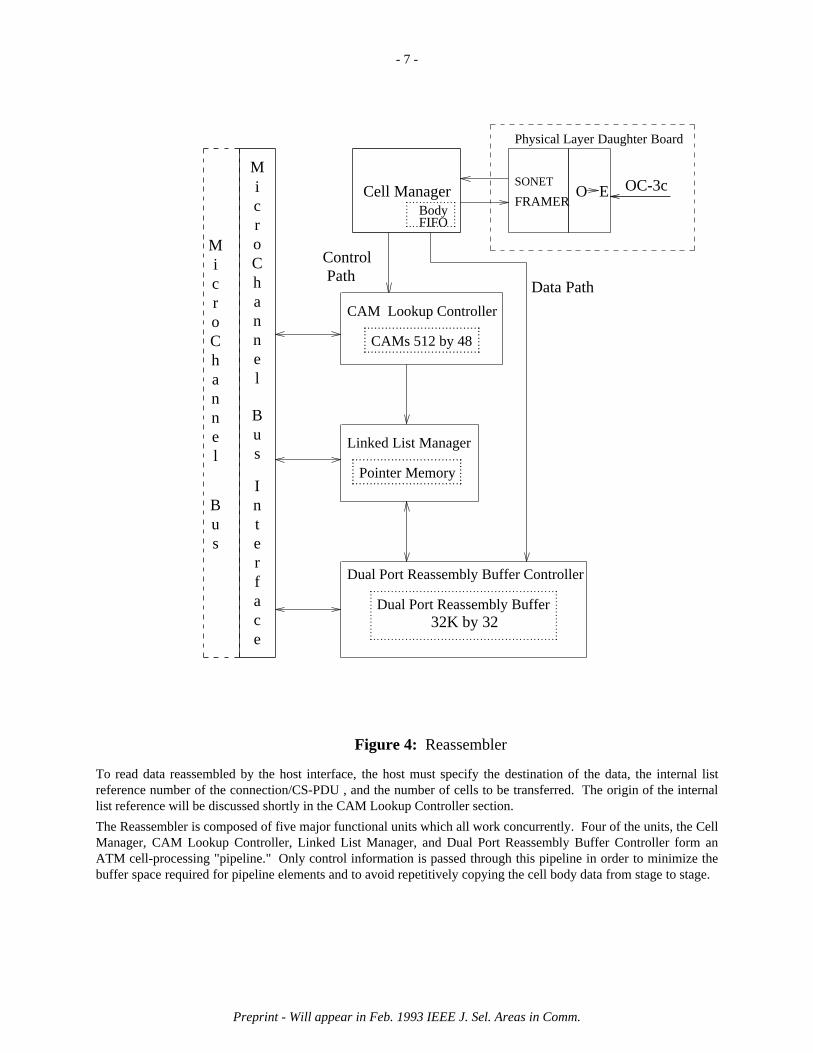
The Reassembler is presented in Figure 4. The Reassembler is able to receive data from the OC-3c network connec-tion, reassemble it, and then deliver the reassembled data to the host’s main memory or to another peripheral card onthe Micro Channel bus.
Preprint - Will appear in Feb. 1993 IEEE J. Sel. Areas in Comm.
- 7 -
.......................................... . . . . . . . . . . . . . . . . . . . . . . . . . . . . . . . .........
CAMs 512 by 48
CAM Lookup Controller
........................................ . . . . . . . . . . . . . . . . . . . . . . . . . . . . . .........
Pointer Memory
Linked List Manager
MicroChannel
Bus
Interface
el
MicroChann
Bus
OC-3cCell ManagerSONET
FRAMER
........................ . . . . . . . . . . . . . .........
BodyFIFO
..................................................................... . . . . . . . . . . . . . . . . . . . . . . . . . . . . . . . . . . . . . . . . . . . . . . . . . . . ................
PathControl
Data Path
O E
Physical Layer Daughter Board
Dual Port Reassembly Buffer Controller
Dual Port Reassembly Buffer32K by 32
Figure 4: Reassembler
To read data reassembled by the host interface, the host must specify the destination of the data, the internal listreference number of the connection/CS-PDU , and the number of cells to be transferred. The origin of the internallist reference will be discussed shortly in the CAM Lookup Controller section.
The Reassembler is composed of five major functional units which all work concurrently. Four of the units, the CellManager, CAM Lookup Controller, Linked List Manager, and Dual Port Reassembly Buffer Controller form anATM cell-processing "pipeline." Only control information is passed through this pipeline in order to minimize thebuffer space required for pipeline elements and to avoid repetitively copying the cell body data from stage to stage.
Preprint - Will appear in Feb. 1993 IEEE J. Sel. Areas in Comm.

- 8 -
3.5.1. Cell Manager
The Cell Manager verifies the integrity of the header and payload (if the cell is carrying AAL4 data) of the cells thatare received by the SONET framer interface to the network by calculating the CRC-8 of the ATM header andCRC-10 of the ATM cell body and comparing them with the values in the cell just received. If the values match, thecell is assumed to be intact. The Cell Manager then extracts the VCI from the ATM header and the MID, segmenttype, and length indicator from the AAL4 header and trailer. While these fields are being extracted and the CRCsare being verified, the cell body is placed in a FIFO buffer for later movement into the dual port reassembly buffer.Since the cell body will be placed into the FIFO buffer before its integrity can be verified, the Cell Manager canrequest that the body be flushed from the FIFO by the Dual Port Reassembly Buffer Controller. These operationstake exactly one cell time, 2.7 µs at the OC-3c rates.
3.5.2. CAM Lookup Controller
The CAM Lookup Controller (CLC) manages two 256 entry (48 bits per entry) content addressable memory (CAM)devices from AMD [2]. One is reserved for virtual circuit traffic while the other is reserved for connectionlesstraffic. Thus, 256 virtual circuit connections and 256 CS-PDUs can be demultiplexed simultaneously. Virtual cir-cuits are identified by their VCI while CS-PDUs are identified by their VCI and MID. We considered using directlookup RAM tables instead of CAMs but decided against this option since for CS-PDUs, the address space is 26 bits(16 bit for VCI + 10 bits for MID). Larger CAMs are available if the 256 virtual circuit connection/CS-PDU limitproves to be confining.
When a VCI or VCI+MID is received from the Cell Manager, the CLC searches the appropriate CAM for a match-ing entry. If none is found and an unused entry is available, the CLC assumes that the identifiers belong to a newlyestablished connection or CS-PDU and writes the identifiers into the empty location. If no entry is available, thecell is dropped. Provided that a match was found, or a new entry was created, the CLC passes the location of thematch or new entry to the Linked List Manager. This location is used as the internal list reference number for theconnection or CS-PDU .
The host is able to read the contents of each CAM entry to associate internal reference numbers with theircorresponding VCI or VCI+MID. The host is also able to delete entries which are no longer active. A delete opera-tion will remove the entry from the CAM. It also requests that the data structures associated with that internal refer-ence at later stages in the pipeline be deallocated.
Next Node in ListReassembly Buffer Pointer
Next Node in ListReassembly Buffer Pointer# of Cells in List
Last Node in ListFirst Node in List
48 Byte Cell Body 48 Byte Cell Body
. . . . . . . . . . . . . . . . . . Nil
Dual Port Reassembly Buffer
Pointer Table
Virtual Circuit Identifier (VCI) Virtual Circuit CAM (256 Entries)
Figure 5: Control Structures for Virtual Circuit Reassembly
The CLC requires a maximum of eleven 50 ns clock cycles (550 ns) to perform the processing required for a cell.
Preprint - Will appear in Feb. 1993 IEEE J. Sel. Areas in Comm.
- 9 -
3.5.3. Linked List Manager
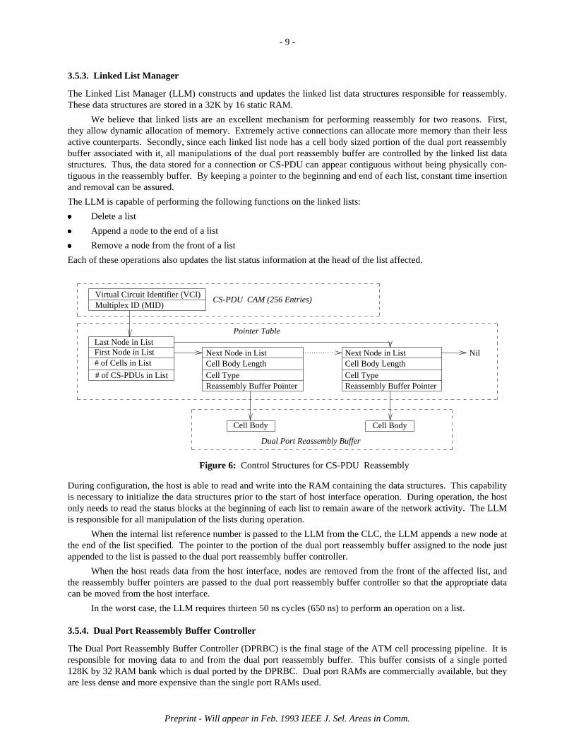
The Linked List Manager (LLM) constructs and updates the linked list data structures responsible for reassembly.These data structures are stored in a 32K by 16 static RAM.
We believe that linked lists are an excellent mechanism for performing reassembly for two reasons. First,they allow dynamic allocation of memory. Extremely active connections can allocate more memory than their lessactive counterparts. Secondly, since each linked list node has a cell body sized portion of the dual port reassemblybuffer associated with it, all manipulations of the dual port reassembly buffer are controlled by the linked list datastructures. Thus, the data stored for a connection or CS-PDU can appear contiguous without being physically con-tiguous in the reassembly buffer. By keeping a pointer to the beginning and end of each list, constant time insertionand removal can be assured.
The LLM is capable of performing the following functions on the linked lists:� Delete a list� Append a node to the end of a list� Remove a node from the front of a list
Each of these operations also updates the list status information at the head of the list affected.
Cell BodyCell Body
Multiplex ID (MID)Virtual Circuit Identifier (VCI)
# of Cells in List
Last Node in ListFirst Node in List
# of CS-PDUs in List
Next Node in List
Reassembly Buffer Pointer
Cell Body LengthCell Type
Next Node in List
Reassembly Buffer Pointer
Cell Body LengthCell Type
. . . . . . . . . . . . . . . . . . Nil
Pointer Table
CS-PDU CAM (256 Entries)
Dual Port Reassembly Buffer
Figure 6: Control Structures for CS-PDU Reassembly
During configuration, the host is able to read and write into the RAM containing the data structures. This capabilityis necessary to initialize the data structures prior to the start of host interface operation. During operation, the hostonly needs to read the status blocks at the beginning of each list to remain aware of the network activity. The LLMis responsible for all manipulation of the lists during operation.
When the internal list reference number is passed to the LLM from the CLC, the LLM appends a new node atthe end of the list specified. The pointer to the portion of the dual port reassembly buffer assigned to the node justappended to the list is passed to the dual port reassembly buffer controller.
When the host reads data from the host interface, nodes are removed from the front of the affected list, andthe reassembly buffer pointers are passed to the dual port reassembly buffer controller so that the appropriate datacan be moved from the host interface.
In the worst case, the LLM requires thirteen 50 ns cycles (650 ns) to perform an operation on a list.
3.5.4. Dual Port Reassembly Buffer Controller
The Dual Port Reassembly Buffer Controller (DPRBC) is the final stage of the ATM cell processing pipeline. It isresponsible for moving data to and from the dual port reassembly buffer. This buffer consists of a single ported128K by 32 RAM bank which is dual ported by the DPRBC. Dual port RAMs are commercially available, but theyare less dense and more expensive than the single port RAMs used.
Preprint - Will appear in Feb. 1993 IEEE J. Sel. Areas in Comm.

- 10 -
The DPRBC is able to move a cell body from the FIFO associated with the Cell Manager into the reassemblybuffer in 2.4 µs (cell time is 2.7 µs). A cell body can be extracted from the buffer for movement across the bus in1.2 µs, the minimum time required to move the data across the bus.
4. Host Software Support
As remarked in the introduction, software plays a key role in the achievement of high end-to-end networking perfor-mance. The abstraction provided by the hardware is of a device which can transfer arbitrarily-sized data unitsbetween a network and system memory. The software must build upon this abstraction to satisfy application require-ments. A significant constraint on such software is its embedding in the framework of an operating system whichsatisfies other (possibly conflicting) requirements. Particular application needs include transfer of data intoapplication-private address spaces, connection management, high throughput, low latency, and the ability to supportboth traditional bursty data communications traffic and the sustained bandwidth requirements of applications usingcontinuous media.
The software operating on the host is usually partitioned functionally into a series of layers; typically, eachsoftware layer contains several of the protocol layers outlined in the introduction. The applications are typicallyexecutable programs, or groups of such programs cooperating on a task, which a user might invoke. Applicationswhich require network access obtain it via abstract service primitives such as read(), write(), and sendto(). Theseservice primitives provide access to an implementation of some layers of the network protocol, as in the UNIX
system’s access to TCP/IP through the socket abstraction. The protocol is often designed to mask the behavior of thenetwork and the hardware connecting the computer to the network, and its implementation can usually be split intodevice-independent and device-dependent portions.
Significant portions of protocol implementations are often embedded in the operating system of the host,where the service primitives are system entry points, and the device-dependent portion is implemented as a ‘‘devicedriver.’’ Such device drivers often have a rigidly specified programmer interface, mainly so that the device-independent portions of system software can form a reasonable abstraction of their behavior. Placement of the pro-tocol functions within the operating system is dictated by two factors, policies and performance. The key policieswhich an operating system can enforce through its scheduling are fairness (e.g., in multiplexing packet streams) andthe prevention of starvation. High performance may require the ability to control timing and task scheduling, theability to manipulate virtual memory directly, the ability to fully control peripheral devices, and the ability to com-municate efficiently (e.g., with a shared address space). All of these requirements can be met by embedding theprotocol functions in the host operating system. In practice, the main freedoms for the host interface designer lie inthe design of the device driver, since it forms the boundary between the host’s device independent software and thefunctions performed by the device.
Interfacing a workstation-class machine to an ATM network provides some particular problems, opportunities andchallenges for a designer implementing such software, particularly in policy decisions such as the host operatingsystem’s management strategy for the host interface. Four observations are particularly helpful in the design pro-cess.
1. Unlike mainframes, supercomputers or minicomputers, workstations are rarely a shared resource, and they typi-cally have cycles to spare.
2. Egalitarian scheduling policies (e.g., the I/O multiplexor-like strategy employed by UNIX [26] and its deriva-tives) have made real-time awkward, and yet many proposed applications require accurately paced datadelivery.
3. Interrupt-handling overhead is large (for example, a save/restore of the RISC System/6000’s registers is 256bytes versus the 48 byte ATM payload) and effects a significant reduction in cache [24] effectiveness. As largerregister files and caches have pushed data processing speeds higher and higher, interrupt service has becomemore and more expensive relative to instruction processing. Full interrupt service per ATM cell would severelylimit the workstation’s network bandwidth, as well as leaving little capacity for applications.
4. Workstation architectures have been optimized for data processing rather than data movement, and manycost/performance tradeoffs have kept the system memory bandwidth relatively low in respect to instruction pro-cessing rates. Unfortunately, the result of this is architectures which have memory or bus bandwidths closelymatched to network bandwidths, thus memory access must be minimized, e.g., by reducing copying of data.
Given these observations, the software architect is presented with the following choices as to implementation
Preprint - Will appear in Feb. 1993 IEEE J. Sel. Areas in Comm.

- 11 -
strategy:
1. Based on the capabilities of the interface (e.g., its provision for programmed I/O, DMA, and streaming), whatis the partitioning of functionality between the host software and the host interface hardware? For example,use of DMA or streaming removes the need for a copying loop in the device driver to process programmedI/O, but may require a variety of locks and scheduling mechanisms to support the concurrent activities ofcopying and processing. Poor partitioning of functions can force the host software to implement a complexprotocol for communicating with the interface, and thereby reduce performance.
2. Should existing protocol implementations be supported? On the one hand, many applications are immediatelyavailable when an existing implementation is supported, e.g., TCP/IP or XNS. On the other, significant per-formance (and hopefully new applications) can be gained by ignoring existing stacks in favor of stacks optim-ized to the new Gbps networks and interface hardware, using a new programmer interface. Or, both stackscould be supported, at a significant cost in effort; this allows both older applications and new applicationswith greater bandwidth requirements to coexist.
3. How are services provided to applications? One key example is the support for paced data delivery, used formultimedia applications. As the host interface software is a component in timely end-to-end delivery, it mustsupport real-time data delivery. This implies provision for process control, timers, etc. in the driver software.
4. How do design choices affect the remainder of the system? The host interface software may be assigned ahigh priority, causing delays or losses elsewhere in the system. Use of polling for real-time service may affectother interrupt service latencies. The correct choices for tradeoffs here are entirely a function of the worksta-tion user’s desire for, and use of, network services. While any tradeoffs should not preclude interaction withother components of the system, e.g., storage devices or framer buffers, increasing demand for network ser-vices should bias decisions towards delivering network subsystem performance.
The use of workstations permits a bias towards networking performance, as they are often used in combination withother workstations in an aggregate connected by a network, and each workstation is in practice a personal machine(or shared by a very small user population). This bias permits us to explore strategies which address networkingperformance with less concern for their implications than might be necessary if a large mainframe environment withheavy multiprocessing loads was under study. Given the cost of interrupts and their effect on processor perfor-mance, strategies which reduce the number of interrupts per data transfer can be employed [22]. An example wouldusing an interrupt only as an event indicator. The transfer of bursts of ATM cells may arise as a consequence of themismatch between larger application data units and the ATM payload of 48 bytes would be accomplished in ascheduled manner, e.g., using polling.
4.1. Implementation
UNIX and its derivatives are the development platform for almost all host software research, as they are the dom-inant operating systems on workstation-class machines. These systems unfortunately impose a number of additionalconstraints on the designer, in particular, the high cost of system calls due to their generality and the crossing of anapplication/kernel address space protection boundary. Pu, et al. [25] report that over 1000 instructions are executedby a read() call before any data is actually read. UNIX also embeds a number of policy decisions about scheduling,which as indicated above, is event-driven and designed to support interactive computing for large numbers of users.While several UNIX derivatives have been modified to support ‘‘real-time’’ behavior, these are non-standard, mak-ing solutions dependent on them non-portable. A number of other evolutions in UNIX, however, appear promisingfor high performance implementations and efficient application-kernel, such as shared memory, memory-mappedfiles, and provision for concurrency control primitives such as semaphores.
The current host interface support software consists of an AIX character-special [26] device driver, of whichseveral versions exist. Multiple versions have been implemented so that we could test various hypotheses about theeffects of data copying and bus transfer modes on achieving high performance. One of the versions copies data toand from large kernel buffers which serve as staging areas for the transfers to and from application address spaces.The other version we discuss here enables the host interface hardware to copy data directly from the applicationaddress space. Since our main focus was understanding the host interface architecture, we have not yet imple-mented a complete protocol stack.
The driver employs AIX’s capability to support dynamically-loadable device drivers; this allowed develop-ment without access to kernel source code for recompilation. The next section describes startup processing common
Preprint - Will appear in Feb. 1993 IEEE J. Sel. Areas in Comm.

- 12 -
to all driver software; later sections are devoted to particular driver functions and discussion of the alternativeimplementation strategies.
4.1.1. Driver Set-up and access
The driver can be configured into the system at boot time if the device is detected on the Micro Channel, or laterunder program control. The host interface presents a unique device identifier when probed, and this identifier isused to gather descriptive information (including driver routines) from a system object database. This description isused to ‘‘configure’’ the device into the system. Configuration includes allocating addresses for use by the devicein bus transfers; the device uses these addresses for access to its control registers and to support streaming modetransfers. Another important feature of the configuration process is adding the access routines for the device to the‘‘device switch’’ table used by AIX to direct system calls issued on character special devices to the correct device.
The interface is initialized when the device special file /dev/host{n} is first opened (n is a small integer, 0 onour test system). Initialization consists of probing the device at a distinguished address which causes it to be reset,build data structures in the Reassembler, as well as performing various set-up operations for the device driversoftware. The operations currently include pinning the driver software’s pages into real memory by removing themas candidates for page replacement, and, if kernel buffering is used, allocating two 64KB contiguous buffers whichare also pinned. After initialization, the device and driver are ready for operation; routines for all appropriate AIXcalls (e.g., read(), write(), ioctl(), etc.) are provided. The read() and write() calls perform data transfer operations,while ioctl() is used for control operations such as specifying Virtual Circuit Identifiers to be associated with a par-ticular channel. The code fragment in Section 9 illustrates how a programmer would access the device for writing;this particular fragment is taken from the measurement software used for performance evaluation.
4.1.2. Segmenter Software
The Segmenter software is accessed mainly through the ioctl() and write() system entry points. Ioctl() is employedfor such control tasks as specifying VCIs and MIDs for use in formatting ATM cells; the VCI and MID are speci-fied to the driver on a per-file descriptor basis. They are used to specify header data to the host interface card so thatit can format a series of ATM cells for transmission. Our intention is to use ioctl() for any behavioral specificationfor the Segmenter software, such as bandwidth allocations, maximum delays, and pacing strategies. Data transfer isdone with write(), providing a clean separation between transfer and control interfaces.
When the write() call is invoked on the device, user data is available to the driver through a uio structureelement. If the data is to be put into kernel buffers, it is copied from the user address space into one of the 64Kbuffers. If data is to be copied from the user process address space, the uio structure element is used to mark theapplication pages as pinned, and to obtain a ‘‘cross-memory descriptor’’ which allows the user data to be addressedby a device on the Micro Channel bus. When a hardware-provided status flag on the Segmenter indicates the deviceis inactive, a streaming mode transfer is set up. The software prepares for streaming by initializing a number oftranslation control words (TCWs) [14] in the Micro Channel’s I/O Channel Controller (IOCC). In addition, pagemappings are adjusted for pages in the host memory; the RISC System/6000 uses an Inverted Page Table alsoreferred to as the Page Frame Table (PFT). The TCWs and Page Frame Table entries allow both the device and theCPU to have apparently contiguous access to scattered pages of real memory. This is illustrated in Figure 7.
...
IBM RISCSystem/6000
P.F.Table
REAL
MEM.
PAGES
.
.
....
IOCC TCW
HostInterface
CPU
Figure 7: Illustration of TCW and PFT usage
After the TCWs and other state are set up, the device is presented with the data size and buffer address, which
Preprint - Will appear in Feb. 1993 IEEE J. Sel. Areas in Comm.

- 13 -
initiates the transfer. As mentioned above, two strategies have been explored for data management, one whichcopies user data through kernel buffers in transfers to and from the interface, and one which performs transfersdirectly from the application address space.
In-kernel buffering allows trivial double-buffering; the driver can thus tag a buffer active and return control tothe user process. The combination of a hardware-provided state flag and double-buffering permits overlappedoperation of the host interface and the host processing unit. While this implementation supports overlapped opera-tion, the copying between user and kernel address spaces is potentially a major impediment to high-performanceoperation. The provision for TCWs in the IOCC allows large contiguous transfers directly to and from the addressspace of an AIX user process. This removes the burden of copying data across the protection boundary from thesoftware, imposing it on the hardware portion of the interface architecture. An alternative prototype device driversupports such transfers.
Overlapped operation from user address spaces is somewhat more complex than for transfers from copieskept in kernel buffers, due to the risks inherent in concurrent access to shared state by the device and the process.Two obvious approaches are: (1) blocking (i.e., ceasing execution of) the process until streaming is complete, and(2) trusting the process to not access the data (e.g., the process could do its own double-buffering). The firstapproach prevents a single process from using the hardware’s capability for overlapped operation. This seemsunwise (although it is what we do currently), since most applications use the CPU to transform data which travels toand from the network. The second approach assumes either intelligence or benevolence. However, as we have seenin practice, the inevitable crashes due to inconsistent data in the kernel punish other users for a transgression. Athird approach is to force the process to block (cease execution) when it accesses a ‘‘busy’’ buffer. In this way,‘‘well-behaved’’ processes can achieve maximum overlap, while AIX is protected from the indiscretions of‘‘poorly-behaved’’ processes. This can be accomplished by tagging the active buffer’s PFT entries with ‘‘fault-on-write’’; the process is then blocked until the streaming transfer is complete and the page fault can be resolved. Thiscombines the good features and removes the complications of the other two schemes, and is the approach currentlybeing explored.
4.1.3. Reassembler Software
The Reassembler software is considerably more complex than the Segmenter software, because its activation is con-trolled by external events such as arriving cells. We have avoided the use of interrupts in our interface system [27]due to the software overhead, since with rapid arrival of small data objects (such as ATM cells), the interrupt ser-vice time can exceed the data service time. This remains true for considerably larger aggregations of cells. Withoutinterrupts, however, the host is obligated to poll the interface. For the Segmenter, we poll for completion of astreaming transfer using a status register value indicating that the card is idle; only performance is affected if we aredelayed in observing a transition. On the Reassembler, however, the consequence of a delayed observation may belost data and state inconsistencies between the host and the interface. Thus, the design of the Reassembler softwarerequires support for real-time operations (such as clock-driven polling) and must perform well to keep up with arriv-ing traffic. Much of the additional software complexity of the receiver is support for polled operation.
As described above, the current support software is implemented as an AIX device driver. The Reassemblersoftware operates using mainly three AIX system calls, open(), ioctl(), and read(). Before initialization (for exam-ple, by loading at system boot time or later), the device driver is inactive, but since there are no interrupts from thedevice, this does not affect system integrity. At initialization, a number of data structures are created and processesdependent on these data structures are begun. As in the Segmenter software, the ioctl() system entry point is usedfor control functions and the read() call performs transfer of data. The card-to-host data transfer operations areanalogous to those described for the Segmenter software. Our polling strategy also requires considerable support, inthe form of tables which maintain state associated with the ATM network. The three main data structures are the VCtable, the DG table, and the POLL table.
4.1.3.1. VC table
The hardware supports 256 Virtual Circuit Identifiers (VCIs); a 256-entry table is used to track activity on each vir-tual circuit. Each array element is of type vc_t:
Preprint - Will appear in Feb. 1993 IEEE J. Sel. Areas in Comm.

- 14 -
typedef struct {int vc_status; /* status flags for this VC */struct xmem vc_x; /* pinned pages, d_master()ed area */caddr_t vc_buf; /* parameters for buffer mapped to... */int vc_len; /* ...this virtual circuit */vci_t vc_next; /* identifier of next active VC */vci_t vc_prev; /* identifier of previous active VC */long vc_poll_rate; /* polls per second */long vc_poll_time; /* clock time for next poll */dg_list_t vc_dgs; /* list of CS-PDUs on this VC */
} vc_t;
The vc_x entry is a ‘‘cross-memory descriptor’’ used by AIX to control transfers between processor virtualaddress spaces (e.g., user space) and the Micro Channel’s virtual address space. The vc_buf pointer and thevc_len byte count are used to prevent overwrites of user data, unpin pages when a particular VC is closed, and toremove the cross-memory mapping. The polling strategy uses the vc_next and vc_prev entries to maintain anactive list; the vc_poll_rate and vc_poll_time entries also exist to support polling. The vc_dgs entrypoints to any CS-PDUs which may have arrived on this virtual circuit.
4.1.3.2. DG table
Connectionless data transmission is also supported by the AAL4 [21]. The Reassembler board assembles the CS-PDU and when the CS-PDU is complete, a transfer can be initiated into a processor memory area. We currentlytransfer data from the board into a 64KB buffer allocated from the kernel’s pinned heap. After the CS-PDU hasbeen transferred from the interface, its length is available from a device register; this length is used to copy the datainto buffer areas provided by the user process. The DG table has 256 entries, each of which is quite similar to theVC table entry illustrated above, and is of type dg_t. The polling parameters are deleted, there are no crosspointers to other tables, and no pointers to support doubly-linked lists. The vc_dgs entry of the VC table is sup-ported with dg_list_t, which is the head of a singly-linked list of DG table entries.
4.1.3.3. POLL table
The POLL table is constructed to support polling operations on the VCs; it implements a linked list of pointers toVC table entries. The linked list (which bears considerable resemblance to the data structures used by many UNIX
TTY drivers) is sorted on vc_poll_times, so that the head of the list immediately yields the time to next poll;subtracting the current system clock time from this value yields the time with which a fine-granularity alarm timer isset. Insertion into the list is potentially expensive, since insertion into the ordered list takes linear time. However, thelookup required for polling and deletion of the processed table entry are constant-time operations.
4.1.4. Control Strategy
A periodic timer interrupt is generated using the AIX timer services [15]. The timer interrupt service routine exam-ines the control tables in order to decide which actions are to be taken next. All operations are of short duration(e.g., examining the CAMs on the host interface card) so that several can be performed during the interrupt serviceroutine. In addition, the status of the device and its internal tables are determined, in order to drain active VCs andreceive reassembled CS-PDUs. Logical timers in the tables which have expired are updated and reset when serviceis performed.
AIX on the IBM RISC System/6000 Models 520 and 320 can support timer frequencies up to about 1000Hertz [15] before there are few cycles left for application processing. At a timer frequency of 60 Hertz, at least90% of the processor capacity should remain available to applications. In one sixtieth of a second, about 2.6 Mbitscan arrive on an OC-3c at full rate, and the Reassembler buffer can accommodate 3 Mbits. While less-frequent pol-ling improves throughput and host performance, it has some potentially negative consequences for latency; forexample a 60 Hertz timer would give a worst-case latency of over 16.7 milliseconds before data reached an applica-tion, far slower than desired for many LAN applications [22]. We are currently studying the problem of setting thetimer interval.
Preprint - Will appear in Feb. 1993 IEEE J. Sel. Areas in Comm.

- 15 -
While the Segmenter software is currently not timer-driven, our intention is to add Segmenter service to thetasks performed during clock service, as this would allow best support for isochronous traffic.
4.2. Discussion
We have biased the implementation towards providing high-performance service to network-intensive applications.While we discuss performance in detail in the next section, this realization of host interface software has deliveredapproximately 90% of the performance of the hardware subsystem (comprised of the processor, I/O bus and hostinterface) to applications.
5. Performance Measurements
In this section, we focus on measuring the performance of the implementation. First, we discuss the performance ofthe Segmentation and Reassembly hardware. We then analyze the performance of data transfers across the IBMRISC System/6000 Model 320’s implementation of the Micro Channel Architecture. Finally, we study the perfor-mance of the entire hardware/software transmission architecture using the AIX device drivers discussed in Section4.
5.1. Segmentation and Reassembly Hardware
As of September 1992, the Segmenter and Reassembler have been fully prototyped and tested with an STS-3c phy-sical layer. We are currently in the process of replicating the host interface for use in the AURORA testbed, and pro-viding support for other physical layers including OC-3c and TAXI.
The Segmenter performs as specified in the earlier discussion of Section 3.
The various stages of the Reassembler also perform as specified in the discussion. Assuming that the Reassembleris not required to service any host requests, the limiting component in the pipeline is the LLM. Since the worst caseper cell operation requires 650 ns, and there are 424 bits per cell, the pipeline is capable of processing a networkbandwidth of about 650 Mbps. In actual operation, this bandwidth would be reduced by up to 50% since the hostmust also utilize the LLM to drain cells from the reassembly buffer. Even with this reduction in bandwidth, theReassembler pipeline is still more than capable of support the full bandwidth of an OC-3c connection.
5.2. Micro Channel Architecture Bus Performance
We have carefully studied the performance of data transfers between the host interface and the host’s main memoryon an IBM RISC System/6000 Model 320.
Using 32 bit streaming transfers, we have found that the bus itself is capable of sustained data transfers atslightly less than 320 Mbps, its peak rate for 32 bit transfers. These data rates were observed card-to-card betweenperipherals on the Micro Channel bus. Bus arbitration and stream setup time accounted for the deviation from thepeak rate.
Unfortunately, when transferring data between the host’s main memory and the host interface, significantlylower performance is observed. We determined that the difficulty was with the current implementation of the I/OChannel Controller (IOCC). The IOCC is the connection between the Micro Channel bus and the internal memorybus, illustrated in Figure 8.
Preprint - Will appear in Feb. 1993 IEEE J. Sel. Areas in Comm.

- 16 -
CPU
RS/6000
IOCC
Micro Channel Bus
System MemoryMemory Bus
Figure 8: IOCC location in IBM RISC/System 6000
To minimize the latency of the host’s main memory during a data transfer, the IOCC allocates 16 words of bufferingto each transfer channel. Thus, when a word of main memory is read, 16 words of data are loaded into the IOCC’sbuffers so that consecutive memory accesses are unnecessary.
We have characterized the IOCC’s behavior using a logic analyzer connected to the Micro Channel Bus.Between 2 and 3 µs were required to load the IOCC buffer for every 16 words transferred across the bus. Theactual transfer of 16 words requires only 1.8 µs (200 ns for setup and 100 ns per word transferred). This results in amaximum channel efficiency of 44% or 142 Mbps for data transfer between the host interface and the host’s mainmemory.
We understand that versions of the RISC System/6000 which are about to be released will contain animproved version of the IOCC which will permit a greater utilization of the bandwidth of the Micro Channel bus.
5.3. Software and System Performance
A key test of the various architectural hypotheses presented is their experimental evaluation; since many of theseclaims are related to performance, our experiments are focused on timing and throughput measurements, and ana-lyses of these measurements. Since application performance is the final validation, any experiments should be asclose to true end-to-end experiments as possible. In our case, data should pass from a user process (the application),through the software and hardware subsystems, to the network.
5.3.1. Experimental Setup and possible sources of error
A short AIX program to gather timing measurements was written, of the basic form shown in Figure 9.
Preprint - Will appear in Feb. 1993 IEEE J. Sel. Areas in Comm.

- 17 -
/* testwr.c - main block (no declarations or set-up shown) */
if ((fd = open("/dev/host0", O_WRONLY)) == -1){perror("Couldn’t open dd");exit(-1);
}
gettimeofday( &tv1, &tz );
for(i=0; i<repeats; i++){/* copies added here; memcpy( buf, SOMETHING ); */
if (write(fd, buf, count ) == -1)perror("write failure");
}
gettimeofday( &tv2, &tz );clock = elapsed( tv2, tv1 );
printf( "elapsed time: %d microseconds\n", clock );
Figure 9: Code fragment to access and exercise Segmenter
While the option-handling is not shown for the sake of brevity, the basic options include a repetition count, a buffersize, and a bit pattern with which to populate the buffer. This latter option was included so that recognizable datapatterns would be produced on the logic analyzer used to monitor the experiments. The defaults used are 1, 65536(bytes), and a pattern of bytes derived from a counter. A modified version of this program which recopies the pat-tern into the buffer before each write() system call was also used in the tests (this version gives rise to the solid linesmarked ‘‘with copy’’ in Figures 10-12); the primary version of the program does not do this, as our focus was theperformance of our hardware/software architecture, not RISC System/6000 data movement performance. However,the additional copy may make the measurements more relevant for protocol stacks built above our architecture.
A script which varied the buffer size and number of repetitions to achieve a constant total of bytes was writ-ten. The parameters used ranged from a buffer size of 1KB and repetition count of 8K to a size of 64KB and a countof 128, yielding a total byte count of 8MB. While this may have been too short a test, we verified the measuredvalues by rerunning the 64KB cases with a repetition count of 32K, and this case (2GB) matched the shorter case to3 significant digits. All measurements are repeatable to 3 significant digits of accuracy; at this point, there is‘‘noise’’ due to such factors as background activities on the processor and AIX timing granularity.
These measurements do not reflect the throughput that would be seen by an application using a protocol suitesuch as TCP/IP, although they may reflect an upper bound on the throughput achievable with an implementation ofClark and Tennenhouse’s Application Layer Framing and Integrated Layer Processing [8]. The tests do notrepresent end-to-end throughput measurements between processors across the network, but rather rates sustainableby the host when delivering data to the network.
5.3.2. Measurements
Shown in Figure 10 is the performance of the hardware/software combination for the device driver implemen-tation, where the AIX kernel copies the user buffer data into a kernel buffer and then initiates a streaming transferusing the kernel copy of the buffer as a source.
Preprint - Will appear in Feb. 1993 IEEE J. Sel. Areas in Comm.

- 18 -
1 2 5 10 20 50
50
100
Buffer Size(KB)
B/W(in Mb/s)
with copy
no copy124 Mbps
76 Mbps
Figure 10: Performance of test_wr, streaming from kernel buffers
Figure 11 shows the performance of a driver (please refer to Section 4) which copies the data directly fromthe user address space using the RISC System/6000’s facilities for virtual address translation.
1 2 5 10 20 50
50
100
Buffer Size(KB)
B/W(in Mb/s)
with copy
no copy 124 Mbps
74 Mbps
Figure 11: Performance of test_wr, streaming from user buffers
After the detailed performance analysis of the hardware showing the IOCC bottleneck (discussed below), wemodified the user-buffer driver so that we could measure driver overhead versus other factors such as memorycopying and host memory access performance. This was done by deactivating about 5 lines of code in the driverwhich initiate the streaming transfer, and another 5 lines which poll the host interface status register for completionof the transfer. These results thus correspond to the case of an ‘‘infinitely fast’’ host interface card connected to acurrent generation RISC System/6000 through an infinitely fast Micro Channel Architecture bus.
Preprint - Will appear in Feb. 1993 IEEE J. Sel. Areas in Comm.

- 19 -
1 2 5 10 20 50
1000
2000
3000
Buffer Size(KB)
B/W(in Mb/s)
with copy
no copy
3500 Mbps
175 Mbps
Figure 12: Performance of test_wr, infinitely fast interface subsystem
5.3.3. Discussion of Results
The script described earlier was run on a lightly-loaded IBM RISC System/6000 Model 320. Benchmarking done byanother process showed little or no system performance degradation, even when competing for I/O resources (e.g., aseveral megabyte FTP copying data from a remote IBM PC/RT connected through an Ethernet).
It’s clear from each of the three graphs that for small block sizes, software is the limiting factor to system per-formance. Smaller block sizes force the application to make frequent system calls, which force the AIX system tocontext-switch frequently. Larger block sizes reduce the per-byte software overhead, since the system calls areamortized over a larger data transfer. As this overhead becomes relatively smaller, the data transfer rate dominatesthe performance, and since the software does not participate in actual transfer to and from the device, the hardwareperformance limits discussed in Section 5.2 become the limiting factor. This can be seen by examining the relativeperformance gain for each doubling in block size. The performance is almost doubled as block size is increasedfrom 1KB to 2KB, but the increase from 32KB to 64KB gives only a 10% gain.
For many sources of traffic, the 64KB blocks, and hence the performance figures, may be unrealistic. We arestudying device driver strategies which can give us good performance with smaller block sizes. One such idea is theuse of an area of shared memory to allow the kernel and applications to communicate without system calls, thuseliminating their effect.
6. Conclusions and a Look to the Future
The hardware and software we have designed and implemented performs remarkably well. The cell manipulationlogic on the host interface could operate at over 1 Gbps with minor architectural and implementation technologychanges. Our approach of pursuing architectural solutions, such as concurrent operation (as in the parallelism in thecell processing pipeline), allows us to take advantage of improvements in technology which would allow higherclock speeds. The software experiments positing an ‘‘infinitely fast’’ device show that the software design scaleswell to higher-performance platforms. We were somewhat frustrated in our performance goals by the implementa-tion of the Micro Channel Architecture on the IBM RISC System/6000 Model 320. While the clock rates of thecurrent Micro Channel Architecture could support higher speeds (up to 320Mbps, multiplying data width by theclock rate), the current I/O Channel Controller design limits performance to about 140 Mbps. We were surprised todiscover this bottleneck, as we expected software or the Micro Channel Architecture bus itself to be the limiting fac-tor. It is hard to blame the designers, as networking at this speed was probably not a consideration in bringing themachine to fruition.
We have a number of short term research targets. The first is to interconnect a RISC System/6000 to a
Preprint - Will appear in Feb. 1993 IEEE J. Sel. Areas in Comm.

- 20 -
DECstation 5000 using our host interface and the host interface designed by Davie [17] of Bellcore. This experimentwill lead to the connection of RISC System/6000s to Bellcore’s Sunshine switch [19] in the context of the AURORA
collaboration. We are also porting the segmentation and reassembly hardware architecture for use as a LinkAdapter with the HP 9000/700 series of workstations equipped with the Afterburner network interface card [23]. Toprovide additional connectivity we are working to provide support for the Class 5 AAL and the TAXI physicallayer.
Our colleagues at IBM Research have implemented an ORBIT [10] card for the RISC System/6000’s MicroChannel Architecture; our use of the RISC System/6000 suggests that internetworking PTM and ATM using theRISC System/6000 as a bridge would be a very interesting engineering experiment.
The longer-term research questions raised by these experiments are centered around workstation architec-tures. The RISC System/6000, unlike many current-generation workstations, has adequate memory bandwidth tosupport high-speed networking. I/O channel architectures such as the Micro Channel Architecture provide a numberof attractions, among which are access to other peripherals, structuring, concurrency control, and features such asvirtual address translation by the IOCC. Once the newer IOCC is available, the host’s memory bandwidth should beaccessible to peripherals. Connection to a bus can aid portability across CPU and system architectures; analysis anddebugging of the host interface hardware was done on an IBM PS/2 Model 50 running MS-DOS.
It is unclear how the networking community will resolve its ferocious need for bandwidth, but there seems lit-tle question that workstation vendors must provide higher performance access to computational resources and tomemory. This performance must be available to attached devices and networks, whether through I/O channels ornovel attachment schemes.
7. Notes and Acknowledgments
Bruce Davie and other reviewers of this paper provided detailed and constructive criticisms of this work. DaveFarber planted the seed which started the research, by suggesting the implementation of an ATM to Ethernet bridge.Steve Heimlich helped with guidance in the initial phases of the device driver implementation and Fred Strietel-meier helped us understand the IOCC.
AURORA is a joint research effort undertaken by Bell Atlantic, Bellcore, IBM Research, MIT, MCI, NYNEX,and Penn. AURORA is sponsored as part of the NSF/DARPA Sponsored Gigabit Testbed Initiative through the Cor-poration for National Research Initiatives. NSF (Cooperative Agreement Number NCR-8919038) and DARPA pro-vide funds to the University participants in AURORA. Bellcore is providing support through the DAWN project.IBM has supported this effort by providing RISC System/6000 workstations, and this work was partially supportedby an IBM Faculty Development Award. The Hewlett-Packard Company has supported this effort through dona-tions of laboratory test equipment.
RISC System/6000, AIX, PC/RT, PS/2 and Micro Channel are trademarks of IBM. Ethernet is a trademark ofXerox. TURBOChannel and DECstation are trademarks of Digital Equipment Corporation. UNIX is a trademark ofUNIX Systems Laboratories.
8. References
[1] 82C611, 82C612 MicroCHIPS: Micro Channel Interface Parts, Chips and Technologies, January, 1988.
[2] Am99C10 256 x 48 Content Addressable Memory, Advanced Micro Devices, 1989.
[3] 1992 Data Book, Altera Corporation, 1992.
[4] H. Abu-Amara, T. Balraj, T. Barzilai, and Y. Yemini, ‘‘PSi: A Silicon Compiler for Very Fast Protocol Pro-cessing,’’ in Protocols for High Speed Networks, ed. R. C. Williamson, North-Holland (1989).
[5] Emmanuel A. Arnould, Francois J. Bitz, Eric C. Cooper, Robert D. Sansom, and Peter A. Steenkiste, ‘‘Thedesign of Nectar: A network backplane for heterogeneous multicomputers,’’ in Proceedings, ASPLOS-III(April 1989), pp. 205-216.
[6] H. B. Bakoglu, G. F. Grohoski, and R. K. Montoye, ‘‘The IBM RISC System/6000 processor: Hardware over-view,’’ IBM Journal of Research and Development 34(1), pp. 12-22 (January, 1990).
[7] David D. Clark, Van Jacobson, John Romkey, and Howard Salwen, ‘‘An Analysis of TCP Processing Over-head,’’ IEEE Communications Magazine 27(6), pp. 23-29 (June 1989).
Preprint - Will appear in Feb. 1993 IEEE J. Sel. Areas in Comm.

- 21 -
[8] D. D. Clark and D. L. Tennenhouse, ‘‘Architectural considerations for a new generation of protocols,’’ inProc. ACM SIGCOMM ’90, Philadelphia, PA (September 1990).
[9] D. D. Clark, B. S. Davie, D. J. Farber, I. S. Gopal, B. K. Kadaba, W. D. Sincoskie, J. M. Smith, and D. L.Tennenhouse, ‘‘An Overview of the AURORA Gigabit Testbed,’’ in Proceedings, INFOCOM 1992,Florence, ITALY (1992).
[10] David D. Clark, Bruce S. Davie, David J. Farber, Inder S. Gopal, Bharath K. Kadaba, W. David Sincoskie,Jonathan M. Smith, and David L. Tennenhouse, ‘‘The AURORA Gigabit Testbed,’’ Computer Networks andISDN Systems 25(6), (to appear) (January 1993).
[11] Eric Cooper, Onat Menzilcioglu, Robert Sansom, and Francois Bitz, ‘‘Host Interface Design for ATMLANs,’’ in Proceedings, 16th Conference on Local Computer Networks, Minneapolis, MN (October 14-17,1991), pp. 247-258.
[12] Eric C. Cooper, Peter A. Steenkiste, Robert D. Sansom, and Brian D. Zill, ‘‘Protocol Implementation on theNectar Communication Processor,’’ in Proceedings, SIGCOMM ’90, Philadelphia, PA (September 24-27,1990), pp. 135-144.
[13] IBM Corporation, IBM RISC System/6000 POWERstation and POWERserver: Hardware Technical Refer-ence, Micro Channel Architecture, IBM Order Number SA23-2647-00, 1990.
[14] IBM Corporation, IBM RISC System/6000 POWERstation and POWERserver: Hardware Technical Refer-ence, General Information Manual, IBM Order Number SA23-2643-00, 1990.
[15] IBM Corporation, ‘‘AIX Version 3.1 RISC System/6000 as a Real-Time System,’’ Document NumberGG24-3633-0, Austin, TX (March 1991). International Technical Support Center
[16] Bruce S. Davie, ‘‘Host Interface Design for Experimental, Very High Speed Networks,’’ in Proc. CompconSpring ’90, San Francisco, CA (February 1990), pp. 102-106.
[17] Bruce S. Davie, ‘‘A Host-Network Interface Architecture for ATM,’’ in Proceedings, SIGCOMM 1991,Zurich, SWITZERLAND (September 4-6, 1991), pp. 307-315.
[18] Gary Delp, David Farber, Ronald Minnich, Jonathan M. Smith, and Ming-Chit Tam, ‘‘Memory as a NetworkAbstraction,’’ IEEE Network 5(4), pp. 34-41 (July, 1991).
[19] J. Giacopelli, J. Hickey, W. Marcus, W. D. Sincoskie, and M. Littlewood, ‘‘Sunshine: A High-PerformanceSelf-Routing Broadband Packet Switch Architecture,’’ IEEE Journal on Selected Areas in Communications9(8), pp. 1289-1298 (October, 1991).
[20] David J. Greaves, Derek McAuley, and Leslie J. French, ‘‘Protocol and interface for ATM LANs,’’ inProceedings, 5th IEEE Workshop on Metropolitan Area Networks, Taormina, Italy (May 1992).
[21] CCITT Recommendation I.363, B-ISDN ATM Adaptation Layer (AAL) Specification, 1990.
[22] Hemant Kanakia and David R. Cheriton, ‘‘The VMP Network Adapter Board (NAB): High Performance Net-work Communication for Multiprocessors,’’ in Proceedings, ACM SIGCOMM ’88 (August 16-19 1988),pp. 175-187.
[23] John Lumley, ‘‘A High-Throughput Network Interface to a RISC Workstation,’’ in Proceedings, IEEEWorkshop on the Architecture and Implementation of High-Performance Communications Subsystems (HPCS’92), Tucson, AZ (February 17-19, 1992).
[24] Jeffrey C. Mogul and Anita Borg, ‘‘The effect of context switches on cache performance,’’ in Proceedings,Fourth International Conference on Architectural Support for Programming Languages and Operating Sys-tems (ASPLOS-IV), Santa Clara, CA (April 8-11, 1991), pp. 75-85.
[25] Calton Pu, Henry Massalin, John Ioannidis, and Perry Metzger, ‘‘The Synthesis System,’’ Computing Systems1(1) (1988).
[26] K.L. Thompson, ‘‘UNIX Implementation,’’ The Bell System Technical Journal 57(6, Part 2), pp. 1931-1946(July-August 1978).
[27] C. Brendan S. Traw and Jonathan M. Smith, ‘‘A High-Performance Host Interface for ATM Networks,’’ inProceedings, SIGCOMM 1991, Zurich, SWITZERLAND (September 4-6, 1991), pp. 317-325.
[28] Martina Zitterbart, ‘‘High-Speed Transport Components,’’ IEEE Network, pp. 54-63 (January 1991).
Preprint - Will appear in Feb. 1993 IEEE J. Sel. Areas in Comm.

- 22 -
Preprint - Will appear in Feb. 1993 IEEE J. Sel. Areas in Comm.


