Embed Size (px)
Citation preview

CK3M-seriesProgrammable Multi-Axis ControllerHardware
User's Manual
CK3M-CPU1£1CK3W-PD048CK3W-AX1414£/1515£
Programmable Multi-Axis Controller
O036-E1-01

NOTE• All rights reserved. No part of this publication may be reproduced, stored in a retrieval system, or
transmitted, in any form, or by any means, mechanical, electronic, photocopying, recording, or oth-erwise, without the prior written permission of OMRON.
• No patent liability is assumed with respect to the use of the information contained herein.Moreover, because OMRON is constantly striving to improve its high-quality products, the informa-tion contained in this manual is subject to change without notice.
• Every precaution has been taken in the preparation of this manual. Nevertheless, OMRON as-sumes no responsibility for errors or omissions.Neither is any liability assumed for damages resulting from the use of the information contained inthis publication.
Trademarks• Microsoft, Windows, Windows Vista, Excel, and Visual Basic are either registered trademarks or
trademarks of Microsoft Corporation in the United States and other countries.
• EtherCAT® is registered trademark and patented technology, licensed by Beckhoff AutomationGmbH, Germany.
Other company names and product names in this document are the trademarks or registered trade-marks of their respective companies.
Copyrights• Microsoft product screen shots reprinted with permission from Microsoft Corporation.• This product incorporates certain third party software. The license and copyright information associ-
ated with this software is available at http://www.fa.omron.co.jp/nj_info_e/.

IntroductionThank you for purchasing a CK3M-series Programmable Multi-Axis Controller (may be called MotionController hereinafter).This manual contains information that is necessary to use the CK3M-series Programmable Multi-AxisController. Please read this manual and make sure you understand the functionality and performanceof the product before you attempt to use it in a control system.Keep this manual in a safe place where it will be available for reference during operation.
Intended AudienceThis manual is intended for the following personnel, who must also have knowledge of electrical sys-tems (electrical engineers or the equivalent).• Personnel in charge of introducing FA systems.• Personnel in charge of designing FA systems.• Personnel in charge of installing and maintaining FA systems.• Personnel in charge of managing FA systems and facilities.
Applicable ProductsThis manual covers the following products.• CK3M-series Programmable Multi-Axis Controller
CK3M-CPU1£1CK3W-PD048CK3W-AX1414£/1515£
Introduction
1CK3M-series Programmable Multi-Axis Controller User's Manual Hardware (O036)
Manual Structure
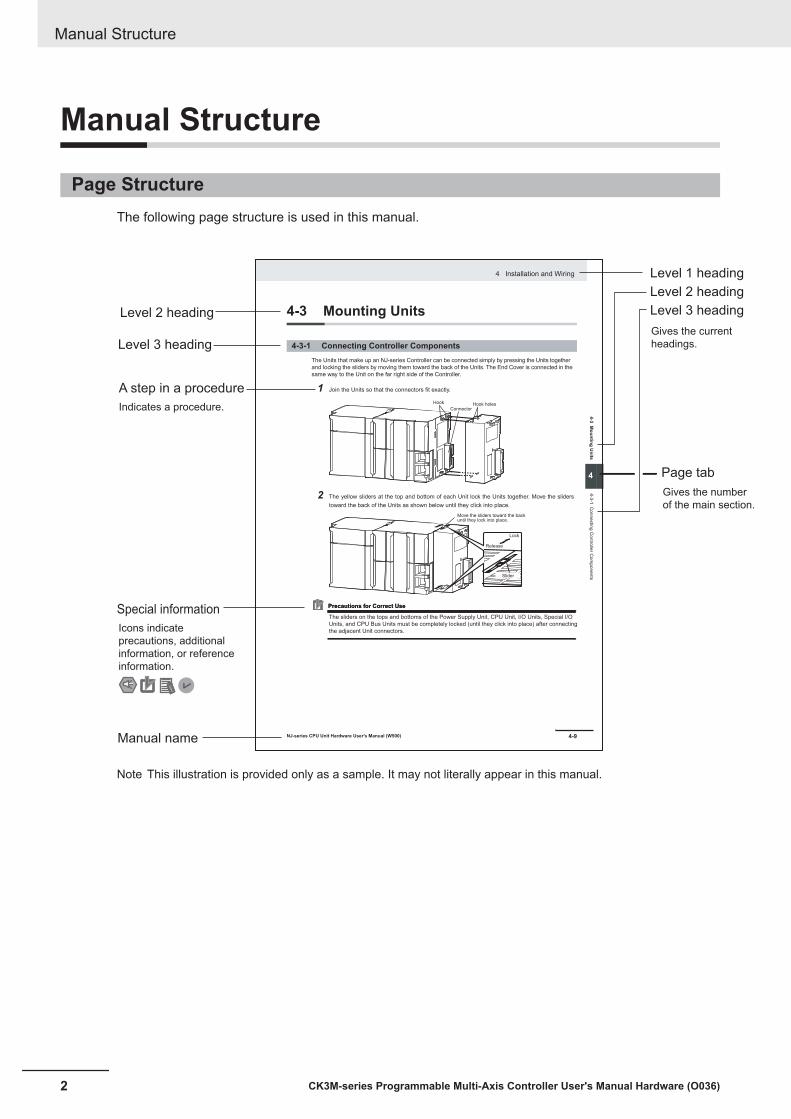
Page StructureThe following page structure is used in this manual.
4-9
4 Installation and Wiring
NJ-series CPU Unit Hardware User’s Manual (W500)
sti
nU
gni
tn
uo
M
3-4
4
s tn
en
op
mo
C r
ellor
tn
oC
gni
tc
en
no
C
1-3-
4
4-3 Mounting Units
The Units that make up an NJ-series Controller can be connected simply by pressing the Units together
and locking the sliders by moving them toward the back of the Units. The End Cover is connected in the
same way to the Unit on the far right side of the Controller.
1 Join the Units so that the connectors fit exactly.
2 The yellow sliders at the top and bottom of each Unit lock the Units together. Move the sliders
toward the back of the Units as shown below until they click into place.
Precautions for Correct UsePrecautions for Correct Use
4-3-1 Connecting Controller Components
Connector
Hook Hook holes
Slider
Lock
Release
Move the sliders toward the back until they lock into place.
Level 1 heading
Level 2 heading
Level 3 headingLevel 2 heading
A step in a procedure
Manual name
Special information
Level 3 heading
Page tab
Gives the current
headings.
Indicates a procedure.
Icons indicate
precautions, additional
information, or reference
information.
Gives the number
of the main section.
The sliders on the tops and bottoms of the Power Supply Unit, CPU Unit, I/O Units, Special I/O
Units, and CPU Bus Units must be completely locked (until they click into place) after connecting
the adjacent Unit connectors.
Note This illustration is provided only as a sample. It may not literally appear in this manual.
Manual Structure
2 CK3M-series Programmable Multi-Axis Controller User's Manual Hardware (O036)

Special InformationSpecial information in this manual is classified as follows:
Precautions for Safe Use
Precautions on what to do and what not to do to ensure safe usage of the product.
Precautions for Correct Use
Precautions on what to do and what not to do to ensure correct operation and performance.
Additional Information
Additional information to read as required.This information is provided to increase understanding and make operation easier.
Manual Structure
3CK3M-series Programmable Multi-Axis Controller User's Manual Hardware (O036)

Manual Structure
4 CK3M-series Programmable Multi-Axis Controller User's Manual Hardware (O036)
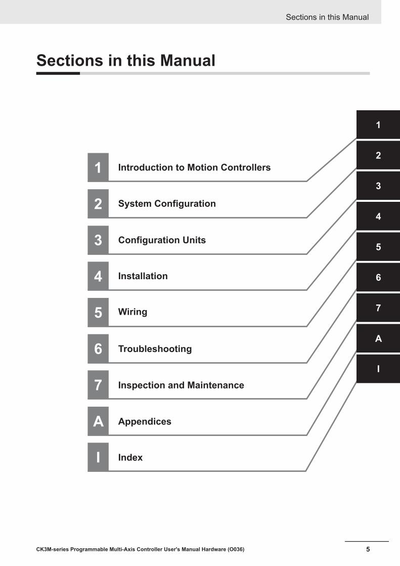
Sections in this Manual
1
2
3
4
5
1
2
3
4
5
A
Introduction to Motion Controllers
System Configuration
Configuration Units
Installation
Wiring
A
6
7
Appendices
6
7
Troubleshooting
Inspection and Maintenance
I
I
Index
Sections in this Manual
5CK3M-series Programmable Multi-Axis Controller User's Manual Hardware (O036)
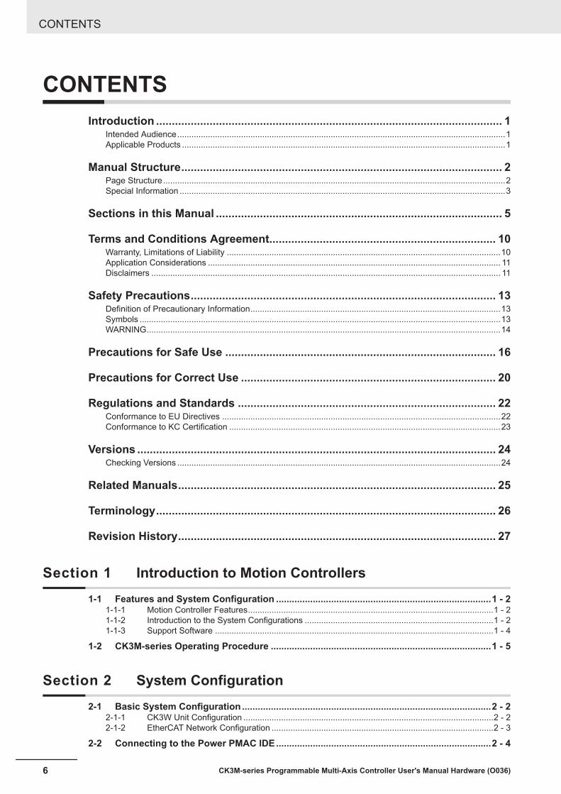
CONTENTSIntroduction .............................................................................................................. 1
Intended Audience...........................................................................................................................................1Applicable Products .........................................................................................................................................1
Manual Structure...................................................................................................... 2Page Structure.................................................................................................................................................2Special Information ..........................................................................................................................................3
Sections in this Manual ........................................................................................... 5
Terms and Conditions Agreement........................................................................ 10Warranty, Limitations of Liability ....................................................................................................................10Application Considerations ............................................................................................................................ 11Disclaimers .................................................................................................................................................... 11
Safety Precautions................................................................................................. 13Definition of Precautionary Information..........................................................................................................13Symbols .........................................................................................................................................................13WARNING......................................................................................................................................................14
Precautions for Safe Use ...................................................................................... 16
Precautions for Correct Use ................................................................................. 20
Regulations and Standards .................................................................................. 22Conformance to EU Directives ......................................................................................................................22Conformance to KC Certification ...................................................................................................................23
Versions .................................................................................................................. 24Checking Versions .........................................................................................................................................24
Related Manuals..................................................................................................... 25
Terminology............................................................................................................ 26
Revision History..................................................................................................... 27
Section 1 Introduction to Motion Controllers1-1 Features and System Configuration ..................................................................................1 - 2
1-1-1 Motion Controller Features........................................................................................................1 - 21-1-2 Introduction to the System Configurations ................................................................................1 - 21-1-3 Support Software ......................................................................................................................1 - 4
1-2 CK3M-series Operating Procedure ....................................................................................1 - 5
Section 2 System Configuration2-1 Basic System Configuration ...............................................................................................2 - 2
2-1-1 CK3W Unit Configuration ..........................................................................................................2 - 22-1-2 EtherCAT Network Configuration ..............................................................................................2 - 3
2-2 Connecting to the Power PMAC IDE..................................................................................2 - 4
CONTENTS
6 CK3M-series Programmable Multi-Axis Controller User's Manual Hardware (O036)
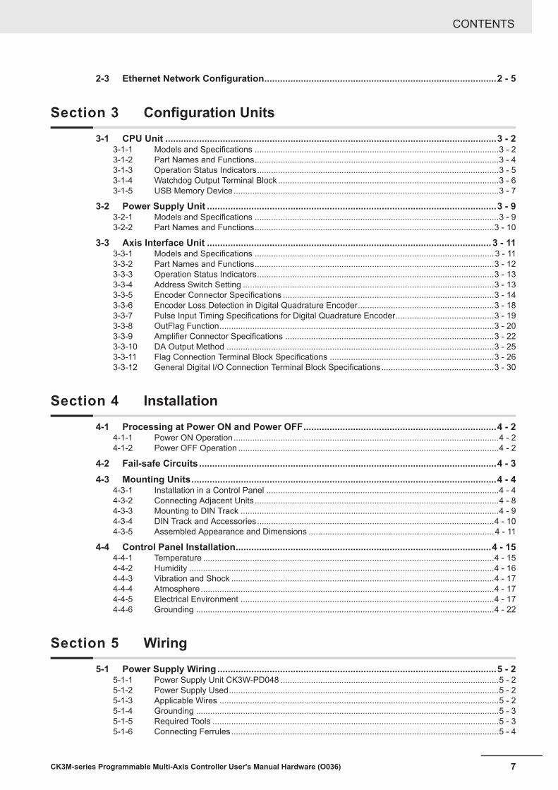
2-3 Ethernet Network Configuration.........................................................................................2 - 5
Section 3 Configuration Units3-1 CPU Unit ...............................................................................................................................3 - 2
3-1-1 Models and Specifications ........................................................................................................3 - 23-1-2 Part Names and Functions........................................................................................................3 - 43-1-3 Operation Status Indicators.......................................................................................................3 - 53-1-4 Watchdog Output Terminal Block ..............................................................................................3 - 63-1-5 USB Memory Device.................................................................................................................3 - 7
3-2 Power Supply Unit ...............................................................................................................3 - 93-2-1 Models and Specifications ........................................................................................................3 - 93-2-2 Part Names and Functions......................................................................................................3 - 10
3-3 Axis Interface Unit ............................................................................................................. 3 - 113-3-1 Models and Specifications ......................................................................................................3 - 113-3-2 Part Names and Functions......................................................................................................3 - 123-3-3 Operation Status Indicators.....................................................................................................3 - 133-3-4 Address Switch Setting ...........................................................................................................3 - 133-3-5 Encoder Connector Specifications ..........................................................................................3 - 143-3-6 Encoder Loss Detection in Digital Quadrature Encoder..........................................................3 - 183-3-7 Pulse Input Timing Specifications for Digital Quadrature Encoder..........................................3 - 193-3-8 OutFlag Function.....................................................................................................................3 - 203-3-9 Amplifier Connector Specifications .........................................................................................3 - 223-3-10 DA Output Method ..................................................................................................................3 - 253-3-11 Flag Connection Terminal Block Specifications ......................................................................3 - 263-3-12 General Digital I/O Connection Terminal Block Specifications................................................3 - 30
Section 4 Installation4-1 Processing at Power ON and Power OFF..........................................................................4 - 2
4-1-1 Power ON Operation.................................................................................................................4 - 24-1-2 Power OFF Operation ...............................................................................................................4 - 2
4-2 Fail-safe Circuits ..................................................................................................................4 - 34-3 Mounting Units.....................................................................................................................4 - 4
4-3-1 Installation in a Control Panel ...................................................................................................4 - 44-3-2 Connecting Adjacent Units ........................................................................................................4 - 84-3-3 Mounting to DIN Track ..............................................................................................................4 - 94-3-4 DIN Track and Accessories.....................................................................................................4 - 104-3-5 Assembled Appearance and Dimensions ...............................................................................4 - 11
4-4 Control Panel Installation..................................................................................................4 - 154-4-1 Temperature ............................................................................................................................4 - 154-4-2 Humidity ..................................................................................................................................4 - 164-4-3 Vibration and Shock ................................................................................................................4 - 174-4-4 Atmosphere.............................................................................................................................4 - 174-4-5 Electrical Environment ............................................................................................................4 - 174-4-6 Grounding ...............................................................................................................................4 - 22
Section 5 Wiring5-1 Power Supply Wiring ...........................................................................................................5 - 2
5-1-1 Power Supply Unit CK3W-PD048 .............................................................................................5 - 25-1-2 Power Supply Used...................................................................................................................5 - 25-1-3 Applicable Wires .......................................................................................................................5 - 25-1-4 Grounding .................................................................................................................................5 - 35-1-5 Required Tools ..........................................................................................................................5 - 35-1-6 Connecting Ferrules..................................................................................................................5 - 4
CONTENTS
7CK3M-series Programmable Multi-Axis Controller User's Manual Hardware (O036)

5-1-7 Connecting Twisted Wires/Solid Wires .....................................................................................5 - 45-1-8 Removing Wires........................................................................................................................5 - 5
5-2 Laying the EtherCAT Network ............................................................................................5 - 65-2-1 Supported Network Topologies .................................................................................................5 - 65-2-2 Installation Precautions .............................................................................................................5 - 75-2-3 Installing EtherCAT Communications Cables............................................................................5 - 8
5-3 Laying the Ethernet Network ............................................................................................5 - 125-3-1 Installation Precautions ...........................................................................................................5 - 125-3-2 Installing Ethernet Networks ...................................................................................................5 - 12
5-4 Watchdog Timer Output Wiring ........................................................................................5 - 155-4-1 Applicable Wires .....................................................................................................................5 - 155-4-2 Required Tools ........................................................................................................................5 - 155-4-3 Connecting Ferrules................................................................................................................5 - 165-4-4 Connecting Twisted Wires/Solid Wires ...................................................................................5 - 165-4-5 Removing Wires......................................................................................................................5 - 17
5-5 USB Memory Device Connection .....................................................................................5 - 185-6 Encoder Connector Wiring ...............................................................................................5 - 19
5-6-1 Connector Arrangement..........................................................................................................5 - 195-6-2 Dedicated Cable......................................................................................................................5 - 20
5-7 Amplifier Connector Wiring ..............................................................................................5 - 235-7-1 Connector Arrangement..........................................................................................................5 - 235-7-2 Dedicated Cable......................................................................................................................5 - 23
5-8 Flag Terminal Block/General I/O Terminal Block Wiring ................................................5 - 255-8-1 Wiring the Terminals................................................................................................................5 - 255-8-2 Precautions When Connecting a Two-wire DC Sensor...........................................................5 - 285-8-3 Precautions When Connecting to General Digital Output .......................................................5 - 30
Section 6 Troubleshooting6-1 Types of Errors.....................................................................................................................6 - 26-2 Using the Indicators to Check Errors ................................................................................6 - 3
6-2-1 Indicator Types..........................................................................................................................6 - 36-2-2 Procedure for Identifying Errors ................................................................................................6 - 4
6-3 Troubleshooting for Errors .................................................................................................6 - 56-3-1 Fatal Errors in the CPU Unit......................................................................................................6 - 56-3-2 Non-fatal errors in the CPU Unit ...............................................................................................6 - 66-3-3 Initialization of CPU Unit Using USB Memory...........................................................................6 - 8
6-4 Sys.Status Register .............................................................................................................6 - 96-4-1 Sys.Status Register List ............................................................................................................6 - 96-4-2 Details of Flags .......................................................................................................................6 - 10
Section 7 Inspection and Maintenance7-1 Cleaning and Maintenance..................................................................................................7 - 2
7-1-1 Cleaning ....................................................................................................................................7 - 27-1-2 Periodic Inspections ..................................................................................................................7 - 2
7-2 Maintenance Procedures ....................................................................................................7 - 47-2-1 Unit Replacement Precautions..................................................................................................7 - 47-2-2 Backup ......................................................................................................................................7 - 47-2-3 Unit Replacement......................................................................................................................7 - 4
AppendicesA-1 General Specifications ....................................................................................................... A - 2
CONTENTS
8 CK3M-series Programmable Multi-Axis Controller User's Manual Hardware (O036)

A-2 Dimensions.......................................................................................................................... A - 3A-2-1 CPU Unit .................................................................................................................................. A - 3A-2-2 Power Supply Unit.................................................................................................................... A - 4A-2-3 Axis Interface Unit .................................................................................................................... A - 4A-2-4 End Cover ................................................................................................................................ A - 5
A-3 Restrictions on Using the NX-series EtherCAT Coupler Unit......................................... A - 6A-4 OMRON Servo Drive Connection Example....................................................................... A - 7
Index
CONTENTS
9CK3M-series Programmable Multi-Axis Controller User's Manual Hardware (O036)

Terms and Conditions Agreement
Warranty, Limitations of Liability
Warranties
Exclusive WarrantyOmron’s exclusive warranty is that the Products will be free from defects in materials and work-manship for a period of twelve months from the date of sale by Omron (or such other period ex-pressed in writing by Omron). Omron disclaims all other warranties, express or implied.
LimitationsOMRON MAKES NO WARRANTY OR REPRESENTATION, EXPRESS OR IMPLIED, ABOUTNON-INFRINGEMENT, MERCHANTABILITY OR FITNESS FOR A PARTICULAR PURPOSE OFTHE PRODUCTS. BUYER ACKNOWLEDGES THAT IT ALONE HAS DETERMINED THAT THEPRODUCTS WILL SUITABLY MEET THE REQUIREMENTS OF THEIR INTENDED USE.
Omron further disclaims all warranties and responsibility of any type for claims or expenses basedon infringement by the Products or otherwise of any intellectual property right.
Buyer RemedyOmron’s sole obligation hereunder shall be, at Omron’s election, to (i) replace (in the form originallyshipped with Buyer responsible for labor charges for removal or replacement thereof) the non-com-plying Product, (ii) repair the non-complying Product, or (iii) repay or credit Buyer an amount equalto the purchase price of the non-complying Product; provided that in no event shall Omron be re-sponsible for warranty, repair, indemnity or any other claims or expenses regarding the Productsunless Omron’s analysis confirms that the Products were properly handled, stored, installed andmaintained and not subject to contamination, abuse, misuse or inappropriate modification. Returnof any Products by Buyer must be approved in writing by Omron before shipment. Omron Compa-nies shall not be liable for the suitability or unsuitability or the results from the use of Products incombination with any electrical or electronic components, circuits, system assemblies or any othermaterials or substances or environments. Any advice, recommendations or information given orallyor in writing, are not to be construed as an amendment or addition to the above warranty.
See http://www.omron.com/global/ or contact your Omron representative for published information.
Limitation on Liability; EtcOMRON COMPANIES SHALL NOT BE LIABLE FOR SPECIAL, INDIRECT, INCIDENTAL, OR CON-SEQUENTIAL DAMAGES, LOSS OF PROFITS OR PRODUCTION OR COMMERCIAL LOSS IN ANY
Terms and Conditions Agreement
10 CK3M-series Programmable Multi-Axis Controller User's Manual Hardware (O036)

WAY CONNECTED WITH THE PRODUCTS, WHETHER SUCH CLAIM IS BASED IN CONTRACT,WARRANTY, NEGLIGENCE OR STRICT LIABILITY.
Further, in no event shall liability of Omron Companies exceed the individual price of the Product onwhich liability is asserted.
Application Considerations
Suitability of UseOmron Companies shall not be responsible for conformity with any standards, codes or regulationswhich apply to the combination of the Product in the Buyer’s application or use of the Product. At Buy-er’s request, Omron will provide applicable third party certification documents identifying ratings andlimitations of use which apply to the Product. This information by itself is not sufficient for a completedetermination of the suitability of the Product in combination with the end product, machine, system, orother application or use. Buyer shall be solely responsible for determining appropriateness of the par-ticular Product with respect to Buyer’s application, product or system. Buyer shall take application re-sponsibility in all cases.
NEVER USE THE PRODUCT FOR AN APPLICATION INVOLVING SERIOUS RISK TO LIFE ORPROPERTY OR IN LARGE QUANTITIES WITHOUT ENSURING THAT THE SYSTEM AS A WHOLEHAS BEEN DESIGNED TO ADDRESS THE RISKS, AND THAT THE OMRON PRODUCT(S) ISPROPERLY RATED AND INSTALLED FOR THE INTENDED USE WITHIN THE OVERALL EQUIP-MENT OR SYSTEM.
Programmable ProductsOmron Companies shall not be responsible for the user’s programming of a programmable Product, orany consequence thereof.
Disclaimers
Performance DataData presented in Omron Company websites, catalogs and other materials is provided as a guide forthe user in determining suitability and does not constitute a warranty. It may represent the result ofOmron’s test conditions, and the user must correlate it to actual application requirements. Actual per-formance is subject to the Omron’s Warranty and Limitations of Liability.
Change in SpecificationsProduct specifications and accessories may be changed at any time based on improvements and oth-er reasons. It is our practice to change part numbers when published ratings or features are changed,or when significant construction changes are made. However, some specifications of the Product may
Terms and Conditions Agreement
11CK3M-series Programmable Multi-Axis Controller User's Manual Hardware (O036)

be changed without any notice. When in doubt, special part numbers may be assigned to fix or estab-lish key specifications for your application. Please consult with your Omron’s representative at anytime to confirm actual specifications of purchased Product.
Errors and OmissionsInformation presented by Omron Companies has been checked and is believed to be accurate; how-ever, no responsibility is assumed for clerical, typographical or proofreading errors or omissions.
Terms and Conditions Agreement
12 CK3M-series Programmable Multi-Axis Controller User's Manual Hardware (O036)
Safety Precautions
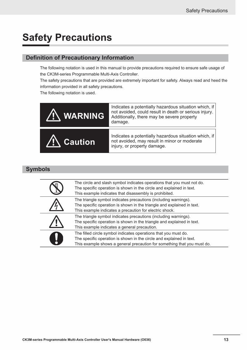
Definition of Precautionary InformationThe following notation is used in this manual to provide precautions required to ensure safe usage ofthe CK3M-series Programmable Multi-Axis Controller.The safety precautions that are provided are extremely important for safety. Always read and heed theinformation provided in all safety precautions.The following notation is used.
Indicates a potentially hazardous situation which, if not avoided, could result in death or serious injury. Additionally, there may be severe property damage.
Indicates a potentially hazardous situation which, if not avoided, may result in minor or moderate injury, or property damage.
WARNING
Caution
Symbols
The circle and slash symbol indicates operations that you must not do.The specific operation is shown in the circle and explained in text.This example indicates that disassembly is prohibited.The triangle symbol indicates precautions (including warnings).The specific operation is shown in the triangle and explained in text.This example indicates a precaution for electric shock.The triangle symbol indicates precautions (including warnings).The specific operation is shown in the triangle and explained in text.This example indicates a general precaution.The filled circle symbol indicates operations that you must do.The specific operation is shown in the circle and explained in text.This example shows a general precaution for something that you must do.
Safety Precautions
13CK3M-series Programmable Multi-Axis Controller User's Manual Hardware (O036)

WARNING
WARNING
During Power SupplyDo not attempt to take any Unit apart.In particular, high-voltage parts are present in the Power Supply Unit while power issupplied or immediately after power is turned OFF. Touching any of these parts mayresult in electric shock. There are sharp parts inside the Unit that may cause injury.
Fail-safe MeasuresProvide safety measures in external circuits to ensure safety in the system if an abnor-mality occurs due to malfunction of the products or due to other external factors affect-ing operation. Not doing so may result in serious accidents due to incorrect operation.
Emergency stop circuits, interlock circuits, limit circuits, and similar safety measuresmust be provided in external control circuits.
You must take fail-safe measures to ensure safety in the event of incorrect, missing, orabnormal signals caused by broken signal lines, momentary power interruptions, orother causes.
The UPS used enables normal operation to continue for a certain period of time if amomentary power interruption occurs. This means that the CK3M-series Controllermay receive incorrect signals from external devices that are also affected by the powerinterruption. Accordingly, take suitable actions, such as establishing external fail-safemeasures and interlock conditions, to monitor the power supply voltage of the externaldevice as required.Unintended outputs may occur if an error occurs in internal data of the Controller. As acountermeasure for such problems, external safety measures must be provided to en-sure safe operation of the system.
The Controller will turn OFF all outputs of output units in the following cases and theslaves will operate according to the settings in the slaves.• If an error occurs in the power supply• If the connected power supply is faulty• If a CPU Unit error (watchdog timer error) or CPU Unit reset occurs• If a major fault level Controller error occurs• While the Controller is on standby until RUN mode is entered after the power is
turned ON• If a system initialization error occursExternal safety measures must be provided to ensure safe operation of the system insuch cases.The product outputs may remain ON or OFF due to deposition or burning of the output relays ordestruction of the output transistors. As a countermeasure for such problems, external safetymeasures must be provided to ensure safe operation of the system.
Safety Precautions
14 CK3M-series Programmable Multi-Axis Controller User's Manual Hardware (O036)
DownloadingAlways confirm safety at the destination before you transfer a user program, configura-tion data, or setup data from the Power PMAC IDE.The devices or machines may perform unexpected operation regardless of the operat-ing mode of the Controller.After you transfer the user program, the Controller is restarted and communicationswith the EtherCAT slaves are cut off. During that period, the slave outputs behave ac-cording to the slave specifications.The time that communications are cut off depends on the EtherCAT network configura-tion.Before you transfer the user program, confirm that the system will not be adversely af-fected.
Test Run
Before you start a Test Run, make sure that the operation parameters are set correctly.
Actual Operation
Check the user program, data, and parameter settings for proper execution before youuse them for actual operation.
Safety Precautions
15CK3M-series Programmable Multi-Axis Controller User's Manual Hardware (O036)
Precautions for Safe Use
Transporting• Do not drop any Unit or subject it to abnormal vibration or shock. Doing so may result in Unit mal-
function or burning.
Mounting• Be sure that the terminal blocks, connectors, and other items with locking devices are correctly
locked into place before use.• When connecting the Power Supply Unit, CPU Unit, and CK3W Unit, connect the units together,
then slide the sliders on the top and bottom until they click into place, and lock securely.• Always mount an end cover for use. Note that if an end cover is not mounted, the Unit may not func-
tion satisfactorily.• The number of Axis Interface Units connected to the CPU Unit must be up to 2 units at maximum.
Installation• Always connect to a ground of 100 Ω or less when installing the Units.• For DIN Track installation, correctly follow the instructions in this manual.
Wiring• Follow the instructions in this manual to correctly perform terminal block and connector wiring and
insertion.Double- check all wiring and connector insertion before turning ON the power supply.
• If the external power supply to a digital output or a slave has polarity, connect it with the correct po-larity.If the polarity is reversed, current may flow in the reverse direction and damage the connected devi-ces regardless of the operation of the Controller.
• Before you connect a computer to the Controller, disconnect the power supply plug of the computerfrom the AC outlet.Also, if the computer has an FG terminal, connect it such that the FG terminal has the same electri-cal potential as the FG on the product.A difference in electrical potential between the computer and the Controller may cause a failure ormalfunction.
• Do not pull on the cables or bend the cables beyond their natural limit.• Do not place heavy objects on top of the cables or other wiring lines. Doing so may break the ca-
bles.• Always use power supply wires with sufficient wire diameters to prevent voltage drop and burning.
Make sure that the current capacity of the wire is sufficient. Otherwise, excessive heat may be gen-erated.
Precautions for Safe Use
16 CK3M-series Programmable Multi-Axis Controller User's Manual Hardware (O036)

When cross-wiring terminals, the total current for all the terminals will flow in the wire. When wiringcross-overs, make sure that the current capacity of each of the wires is not exceeded.
• Do not allow wire clippings, shavings, or other foreign material to enter the Controller. Otherwise,Controller burning, failure, or malfunctions may occur.Cover the Controller or take other suitable countermeasures, in particular when carrying out wiringwork.
• To ensure safe use of the Axis Interface Unit function, observe the following points when wiring toavoid the effects of the noise.a) Use twisted-pair shielded wire for the encoder connection lines and amplifier connection lines.b) Wire the encoder connection lines and amplifier connection lines separately from the AC power
lines, motor power lines, and other power lines, and do not insert into the same duct.c) If there are noise effects from power supply lines when using the same power supply to power
an electrical welder or an electric discharge machine, or there is a high-frequency source nearby,insert a noise filter into the power supply input section.
Power Supply Design• In the system, only use a power supply within the rated supply capacity range specified in this man-
ual.• Install external breakers and take other safety measures against short-circuiting and overcurrents in
external wiring.
Turning ON the Power Supply• It takes approximately several tens of seconds to enter RUN mode after the power supply is turned
ON. During that time, outputs will be OFF or the values will be as according to settings in the Unit orslaves. Also, external communications will not be able to be performed. Implement fail-safe circuitsso that external devices do not operate incorrectly.
• Surge current occurs when the power supply is turned ON. When selecting fuses or breakers forexternal circuits, consider the above precaution and allow sufficient margin in shut-off performance.Refer to this user's manual for surge current specifications.
• Configure the external circuits so that the power supply to the digital output turns ON only after thepower supply to the Controller has turned ON.If the power supply to the Controller is turned ON after the digital output power supply, the digitaloutput may suddenly malfunction when the power supply is turned ON to the Controller.
Actual Operation• Build a program such that the Sys.Status flag is constantly monitored and safe operations are taken
if any errors occur.
Precautions for Safe Use
17CK3M-series Programmable Multi-Axis Controller User's Manual Hardware (O036)

Turning OFF the Power Supply• Do not turn OFF the power supply or remove the USB memory device while the Controller is ac-
cessing the USB memory device. Data may become corrupted, and the Controller will not operatecorrectly if it uses corrupted data.
• Always turn OFF the power supply before you attempt any of the following.a) Mounting or removing the Unitsb) Assembling the Unitsc) Setting rotary switchesd) Connecting cables or wiring the systeme) Connecting or disconnecting the terminal blocks or connectors
• Do not disconnect the cable or turn OFF the power supply to the product when downloading data orprograms from the Support Software. You may be unable to download the correct data, which couldresult in malfunctions.
• Do not turn OFF the power supply when performing write processes to the built-in flash memory.Data may be corrupted, which could result in malfunctions.
OperationConfirm that no adverse effects will occur in the system before you attempt any of the following.• Changing the operating mode of the Controller (including changing operation mode setting when
power is turned ON)• Changing the user program or settings• Changing set values or present values
EtherCAT Communications• Make sure that the communications distance, number of nodes connected, and method of connec-
tion for EtherCAT are within specifications.Do not connect EtherCAT communication to EtherNet/IP, a standard in-house LAN, or other net-works. An overload may cause the network to fail or malfunction.
• If the Fail-soft Operation parameter is set to stop operation, process data communications willstop for all slaves when an EtherCAT communications error is detected in a slave. At that time, theServo Drive will operate according to the Servo Drive specifications. Make sure that the Fail-soft Op-eration parameter setting results in safe operation when a device error occurs.
• If noise occurs or an EtherCAT slave is disconnected from the network, any current communicationsframes may be lost. If frames are lost, slave I/O data is not communicated, and unintended opera-tion may occur. The slave outputs will behave according to the slave specifications. For details, referto the manual for the slave.
• When an EtherCAT slave is disconnected or disabled, communications will stop and control of theoutputs will be lost not only for the disconnected slave, but for all slaves connected after it. Confirmthat the system will not be adversely affected before you disconnect or disable a slave.
• You cannot use standard Ethernet hubs or repeater hubs with EtherCAT communications. If you useone of these, a major fault level error or other error may occur.
• EtherCAT communications are not always established immediately after the power supply is turnedON. Use the system-defined variables and the EtherCAT Coupler Unit device variables in the user
Precautions for Safe Use
18 CK3M-series Programmable Multi-Axis Controller User's Manual Hardware (O036)

program to confirm that I/O data communications are established before attempting control opera-tions.
• If you need to disconnect the cable from an EtherCAT slave during operation, first reset the Ether-CAT and EtherCAT slaves that are connected after it to the Init state, then disconnect the EtherCATslave.
• For EtherCAT and EtherNet, use the connection methods and cables that are specified in this man-ual. Otherwise, communications may be faulty.
• Make sure that all of the slaves to be restored are participating in the network before you reset theEtherCAT Master Function Module. If any slave is not participating in the network when any of theseerrors is reset, the EtherCAT Master Function Module may access a slave with a different node ad-dress than the specified node address, or the error may not be reset correctly.
Motion Control• The motor is stopped if communications are interrupted between the Power PMAC IDE and the
Controller during a Test Run. Connect the communications cable securely and confirm that the sys-tem will not be adversely affected before you perform a Test Run.
• EtherCAT communications are not always established immediately after the power supply is turnedON. Use the system-defined variables in the user program to confirm that communications are es-tablished before attempting control operations.
Unit Replacement• Make sure that the required data, including the user program, configurations, settings, and varia-
bles, is transferred to the Controller that was replaced and to externally connected devices beforerestarting operation.
Maintenance• Do not attempt to disassemble, repair, or modify the Controller. Doing so may result in a malfunction
or fire.• Do not use corrosive chemicals to clean the Controller. Doing so may result in a failure or malfunc-
tion of the Controller.• Dispose of the product according to local ordinances as they apply.
Precautions for Safe Use
19CK3M-series Programmable Multi-Axis Controller User's Manual Hardware (O036)

Precautions for Correct Use
Storage and Installation• Follow the instructions in this manual to correctly perform installation.• Do not operate or store the Controller in the following locations. Doing so may result in burning, in
operation stopping, or in malfunction.a) Locations subject to direct sunlightb) Locations subject to temperatures or humidity outside the range specified in the specificationsc) Locations subject to condensation as the result of severe changes in temperatured) Locations subject to corrosive or flammable gasese) Locations subject to dust (especially iron dust) or saltsf) Locations subject to exposure to water, oil, or chemicalsg) Locations subject to shock or vibration
• Take appropriate and sufficient countermeasures when installing the Controller in the following loca-tions.a) Locations subject to strong, high-frequency noiseb) Locations subject to static electricity or other forms of noisec) Locations subject to strong electromagnetic fieldsd) Locations subject to possible exposure to radioactivitye) Locations close to power lines
• Before touching a Unit, be sure to first touch a grounded metallic object in order to discharge anystatic build-up.
• Install the Controller away from sources of heat and ensure proper ventilation. Not doing so may re-sult in malfunction, in operation stopping, or in burning.
Wiring• Use the rated power supply voltage for the products.
Task Settings• If a Task Period Exceeded error occurs, shorten the programs to fit in the task period or increase the
setting of the task period.
During Operation• Do not disconnect the communications cable while the system is running. Doing so may result in a
failure or malfunction of the system.
Motion Control• Do not download motion control settings during a Test Run.
Precautions for Correct Use
20 CK3M-series Programmable Multi-Axis Controller User's Manual Hardware (O036)
EtherCAT Communications• Set the Servo Drives to stop operation if an error occurs in EtherCAT communications between the
Controller and a Servo Drive.• Always use the specified EtherCAT slave cables. If you use any other cable, the EtherCAT master
or the EtherCAT slaves may detect an error and one of the following may occur.a) Continuous refreshing of process data communications will not be possible.b) Continuous refreshing of process data communications will not end during the set cycle
USB Devices• Always use USB memory devices that comply with the USB standards.
Precautions for Correct Use
21CK3M-series Programmable Multi-Axis Controller User's Manual Hardware (O036)
Regulations and Standards
Conformance to EU Directives
Applicable Directives• EMC Directives
Concepts
EMC DirectivesOMRON devices that comply with EU Directives also conform to the related EMC standards so thatthey can be more easily built into other devices or the overall machine. The actual products havebeen checked for conformity to EMC standards.*1Whether the products conform to the standards in the system used by the customer, however, mustbe checked by the customer. EMC-related performance of the OMRON devices that comply withEU Directives will vary depending on the configuration, wiring, and other conditions of the equip-ment or control panel on which the OMRON devices are installed. The customer must, therefore,perform the final check to confirm that devices and the overall machine conform to EMC standards.
*1. Applicable EMC (Electromagnetic Compatibility) standards are as follows: EMS (Electromagnetic Suscept-ibility): EN61326 EMI (Electromagnetic Interference): EN61326 (Radiated emission: 10-m regulations).
Conformance to EU DirectivesThe CK3M-series Units comply with EU Directives. To ensure that the machine or device in whichthe CK3M-series Units are used complies with EU Directives, the following precautions must be ob-served.• The CK3M-series Units must be installed within a control panel.• You must use double or reinforced insulation power supply for the DC power supplies that are
connected as the Unit power supplies for the CK3M-series Units.We recommend that you use the OMRON S8VK-S series DC Power Supplies. EMC standardcompliance was confirmed for the recommended Power Supplies.
• The CK3M-series Units that comply with EU Directives also conform to the Common EmissionStandard (EN61326). Radiated emission characteristics (10-m regulations) may vary dependingon the configuration of the control panel used, other devices connected to the control panel, wir-ing, and other conditions.You must therefore confirm that the overall machine or equipment in which the CK3M-seriesUnits are used complies with EU Directives.
• This is a Class A product (for industrial environments). In a residential environment, it may causeradio interference. If radio interference occurs, the user may be required to take appropriatemeasures.
Regulations and Standards
22 CK3M-series Programmable Multi-Axis Controller User's Manual Hardware (O036)

Conformance to KC CertificationObserve the following precaution if you use NX-series Units in Korea.
Class A Device (Broadcasting Communications Device for Office Use)This device obtained EMC registration for office use (Class A), and it is intended to be used in placesother than homes.Sellers and/or users need to take note of this.
Regulations and Standards
23CK3M-series Programmable Multi-Axis Controller User's Manual Hardware (O036)
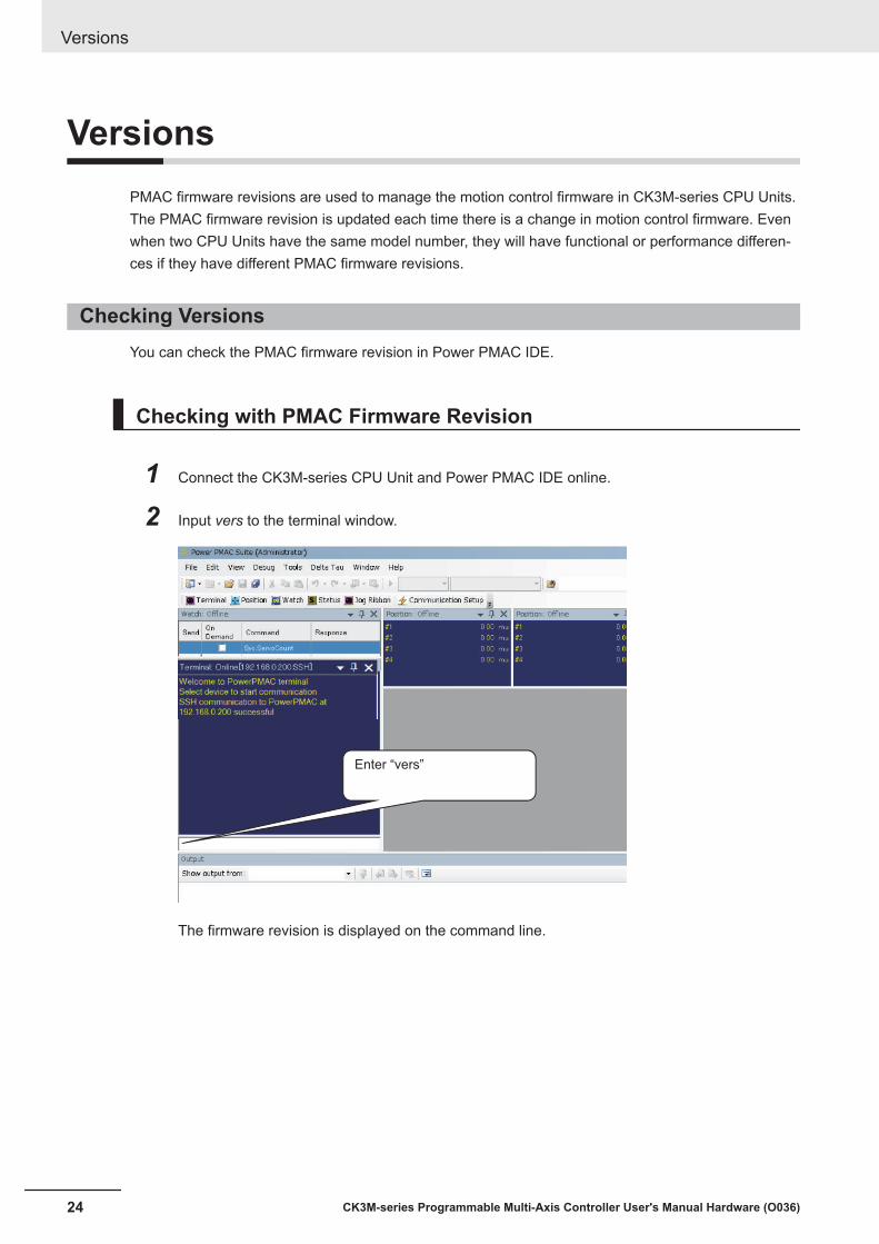
VersionsPMAC firmware revisions are used to manage the motion control firmware in CK3M-series CPU Units.The PMAC firmware revision is updated each time there is a change in motion control firmware. Evenwhen two CPU Units have the same model number, they will have functional or performance differen-ces if they have different PMAC firmware revisions.
Checking VersionsYou can check the PMAC firmware revision in Power PMAC IDE.
Checking with PMAC Firmware Revision
1 Connect the CK3M-series CPU Unit and Power PMAC IDE online.
2 Input vers to the terminal window.
Enter “vers”
The firmware revision is displayed on the command line.
Versions
24 CK3M-series Programmable Multi-Axis Controller User's Manual Hardware (O036)
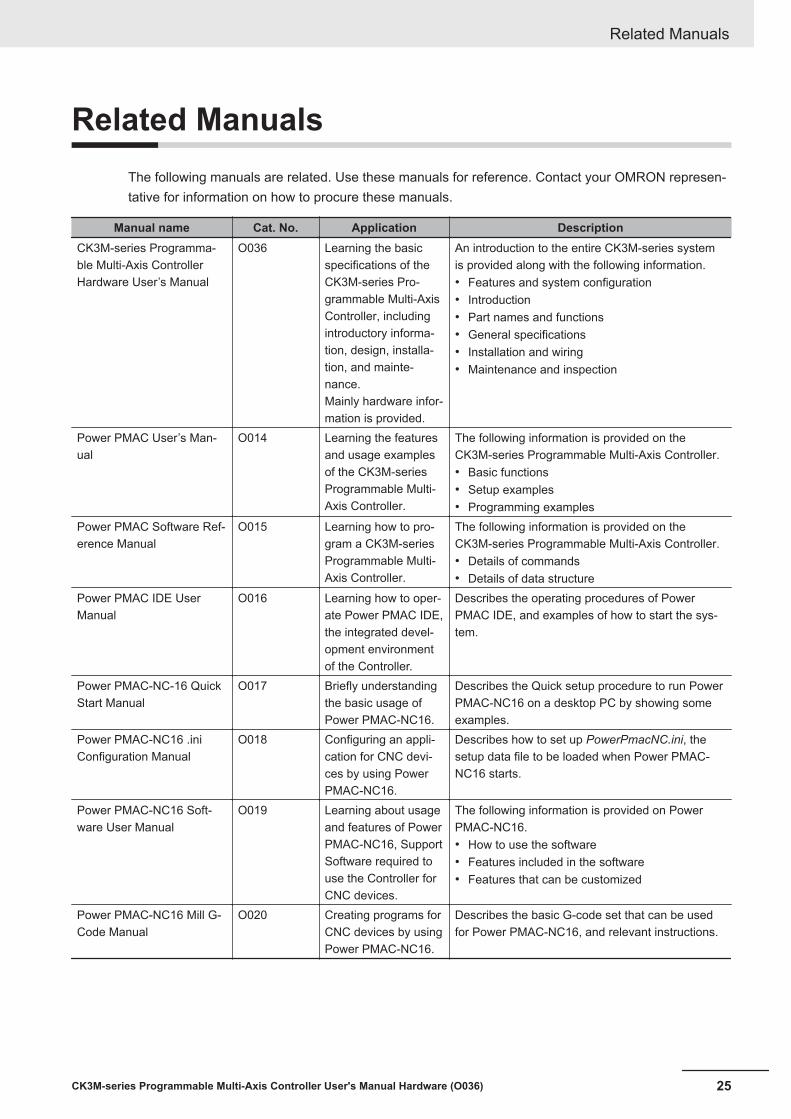
Related ManualsThe following manuals are related. Use these manuals for reference. Contact your OMRON represen-tative for information on how to procure these manuals.
Manual name Cat. No. Application DescriptionCK3M-series Programma-ble Multi-Axis ControllerHardware User’s Manual
O036 Learning the basicspecifications of theCK3M-series Pro-grammable Multi-AxisController, includingintroductory informa-tion, design, installa-tion, and mainte-nance.Mainly hardware infor-mation is provided.
An introduction to the entire CK3M-series systemis provided along with the following information.• Features and system configuration• Introduction• Part names and functions• General specifications• Installation and wiring• Maintenance and inspection
Power PMAC User’s Man-ual
O014 Learning the featuresand usage examplesof the CK3M-seriesProgrammable Multi-Axis Controller.
The following information is provided on theCK3M-series Programmable Multi-Axis Controller.• Basic functions• Setup examples• Programming examples
Power PMAC Software Ref-erence Manual
O015 Learning how to pro-gram a CK3M-seriesProgrammable Multi-Axis Controller.
The following information is provided on theCK3M-series Programmable Multi-Axis Controller.• Details of commands• Details of data structure
Power PMAC IDE UserManual
O016 Learning how to oper-ate Power PMAC IDE,the integrated devel-opment environmentof the Controller.
Describes the operating procedures of PowerPMAC IDE, and examples of how to start the sys-tem.
Power PMAC-NC-16 QuickStart Manual
O017 Briefly understandingthe basic usage ofPower PMAC-NC16.
Describes the Quick setup procedure to run PowerPMAC-NC16 on a desktop PC by showing someexamples.
Power PMAC-NC16 .iniConfiguration Manual
O018 Configuring an appli-cation for CNC devi-ces by using PowerPMAC-NC16.
Describes how to set up PowerPmacNC.ini, thesetup data file to be loaded when Power PMAC-NC16 starts.
Power PMAC-NC16 Soft-ware User Manual
O019 Learning about usageand features of PowerPMAC-NC16, SupportSoftware required touse the Controller forCNC devices.
The following information is provided on PowerPMAC-NC16.• How to use the software• Features included in the software• Features that can be customized
Power PMAC-NC16 Mill G-Code Manual
O020 Creating programs forCNC devices by usingPower PMAC-NC16.
Describes the basic G-code set that can be usedfor Power PMAC-NC16, and relevant instructions.
Related Manuals
25CK3M-series Programmable Multi-Axis Controller User's Manual Hardware (O036)
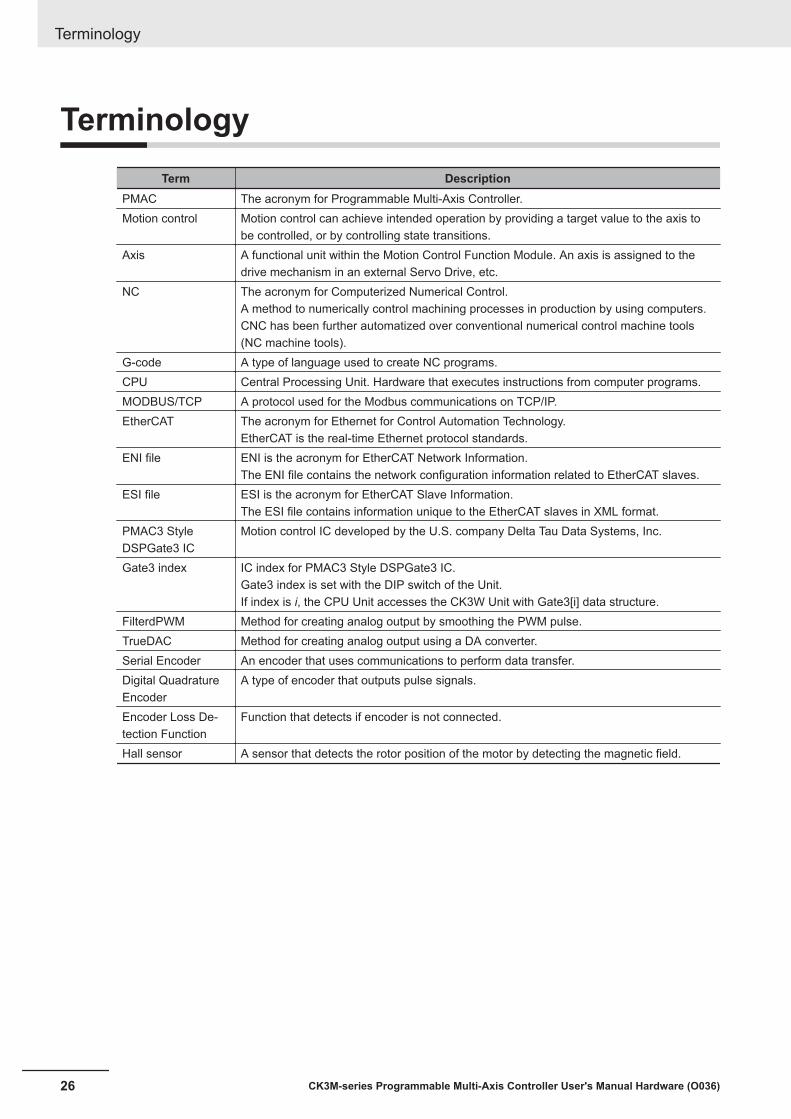
TerminologyTerm Description
PMAC The acronym for Programmable Multi-Axis Controller.Motion control Motion control can achieve intended operation by providing a target value to the axis to
be controlled, or by controlling state transitions.Axis A functional unit within the Motion Control Function Module. An axis is assigned to the
drive mechanism in an external Servo Drive, etc.NC The acronym for Computerized Numerical Control.
A method to numerically control machining processes in production by using computers.CNC has been further automatized over conventional numerical control machine tools(NC machine tools).
G-code A type of language used to create NC programs.CPU Central Processing Unit. Hardware that executes instructions from computer programs.MODBUS/TCP A protocol used for the Modbus communications on TCP/IP.EtherCAT The acronym for Ethernet for Control Automation Technology.
EtherCAT is the real-time Ethernet protocol standards.ENI file ENI is the acronym for EtherCAT Network Information.
The ENI file contains the network configuration information related to EtherCAT slaves.ESI file ESI is the acronym for EtherCAT Slave Information.
The ESI file contains information unique to the EtherCAT slaves in XML format.PMAC3 StyleDSPGate3 IC
Motion control IC developed by the U.S. company Delta Tau Data Systems, Inc.
Gate3 index IC index for PMAC3 Style DSPGate3 IC.Gate3 index is set with the DIP switch of the Unit.If index is i, the CPU Unit accesses the CK3W Unit with Gate3[i] data structure.
FilterdPWM Method for creating analog output by smoothing the PWM pulse.TrueDAC Method for creating analog output using a DA converter.Serial Encoder An encoder that uses communications to perform data transfer.Digital QuadratureEncoder
A type of encoder that outputs pulse signals.
Encoder Loss De-tection Function
Function that detects if encoder is not connected.
Hall sensor A sensor that detects the rotor position of the motor by detecting the magnetic field.
Terminology
26 CK3M-series Programmable Multi-Axis Controller User's Manual Hardware (O036)

Revision HistoryA manual revision code appears as a suffix to the catalog number on the front and back covers of themanual.
O036-E1-01
Revision code
Revisioncode Date Revised content
01 July 2018 Original production
Revision History
27CK3M-series Programmable Multi-Axis Controller User's Manual Hardware (O036)

Revision History
28 CK3M-series Programmable Multi-Axis Controller User's Manual Hardware (O036)

1Introduction to Motion Controllers
This section describes the features, system configuration, and operating procedure ofa CK3M-series Programmable Multi-Axis Controller.
1-1 Features and System Configuration .......................................................... 1 - 21-1-1 Motion Controller Features ........................................................................... 1 - 21-1-2 Introduction to the System Configurations.................................................... 1 - 21-1-3 Support Software .......................................................................................... 1 - 4
1-2 CK3M-series Operating Procedure............................................................. 1 - 5
1 - 1CK3M-series Programmable Multi-Axis Controller User's Manual Hardware (O036)
1
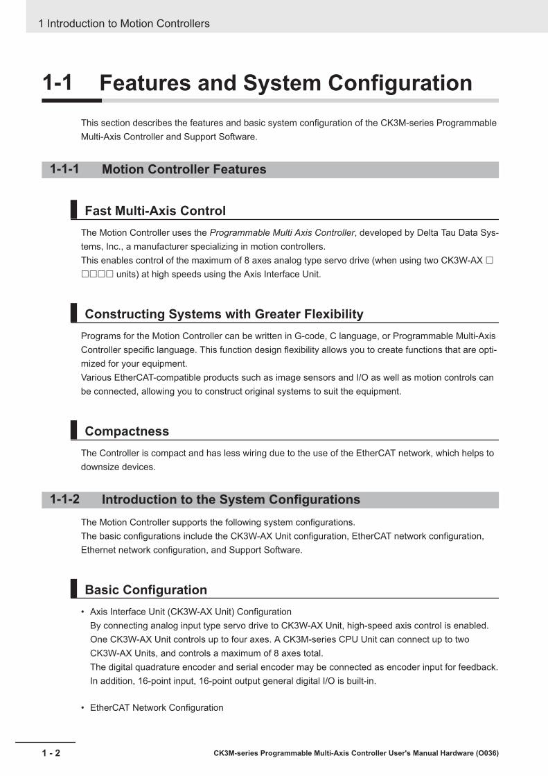
1-1 Features and System ConfigurationThis section describes the features and basic system configuration of the CK3M-series ProgrammableMulti-Axis Controller and Support Software.
1-1-1 Motion Controller Features
Fast Multi-Axis ControlThe Motion Controller uses the Programmable Multi Axis Controller, developed by Delta Tau Data Sys-tems, Inc., a manufacturer specializing in motion controllers.This enables control of the maximum of 8 axes analog type servo drive (when using two CK3W-AX £££££ units) at high speeds using the Axis Interface Unit.
Constructing Systems with Greater FlexibilityPrograms for the Motion Controller can be written in G-code, C language, or Programmable Multi-AxisController specific language. This function design flexibility allows you to create functions that are opti-mized for your equipment.Various EtherCAT-compatible products such as image sensors and I/O as well as motion controls canbe connected, allowing you to construct original systems to suit the equipment.
CompactnessThe Controller is compact and has less wiring due to the use of the EtherCAT network, which helps todownsize devices.
1-1-2 Introduction to the System ConfigurationsThe Motion Controller supports the following system configurations.The basic configurations include the CK3W-AX Unit configuration, EtherCAT network configuration,Ethernet network configuration, and Support Software.
Basic Configuration• Axis Interface Unit (CK3W-AX Unit) Configuration
By connecting analog input type servo drive to CK3W-AX Unit, high-speed axis control is enabled.One CK3W-AX Unit controls up to four axes. A CK3M-series CPU Unit can connect up to twoCK3W-AX Units, and controls a maximum of 8 axes total.The digital quadrature encoder and serial encoder may be connected as encoder input for feedback.In addition, 16-point input, 16-point output general digital I/O is built-in.
• EtherCAT Network Configuration
1 Introduction to Motion Controllers
1 - 2 CK3M-series Programmable Multi-Axis Controller User's Manual Hardware (O036)
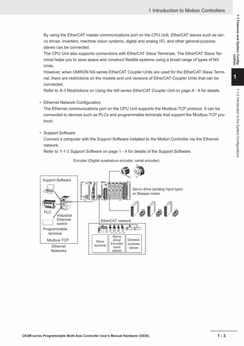
By using the EtherCAT master communications port on the CPU Unit, EtherCAT slaves such as ser-vo drives, inverters, machine vision systems, digital and analog I/O, and other general-purposeslaves can be connected.The CPU Unit also supports connections with EtherCAT Slave Terminals. The EtherCAT Slave Ter-minal helps you to save space and construct flexible systems using a broad range of types of NXUnits.However, when OMRON NX-series EtherCAT Coupler Units are used for the EtherCAT Slave Termi-nal, there are restrictions on the models and unit versions of EtherCAT Coupler Units that can beconnected.Refer to A-3 Restrictions on Using the NX-series EtherCAT Coupler Unit on page A - 6 for details.
• Ethernet Network ConfigurationThe Ethernet communications port on the CPU Unit supports the Modbus-TCP protocol. It can beconnected to devices such as PLCs and programmable terminals that support the Modbus-TCP pro-tocol.
• Support SoftwareConnect a computer with the Support Software installed to the Motion Controller via the Ethernetnetwork.Refer to 1-1-3 Support Software on page 1 - 4 for details of the Support Software.
Encoder (Digital quadrature encoder, serial encoder)
Servo drive (analog input type)
or Stepper motor
EtherCAT network
Support Software
PLCIndustrialEthernetswitch
Programmable
terminal
Ethernet
Networks
Modbus-TCP Slave
terminal
Servo drive/
Encoder input
slaves
General-
purpose
slaves
1 Introduction to Motion Controllers
1 - 3CK3M-series Programmable Multi-Axis Controller User's Manual Hardware (O036)
1-1 Features and System C
onfig-uration
1
1-1-2 Introduction to the System C
onfigurations
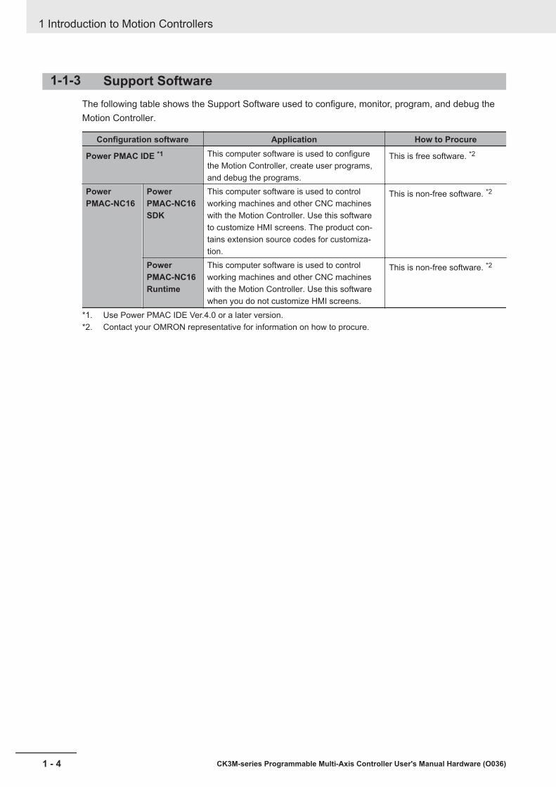
1-1-3 Support SoftwareThe following table shows the Support Software used to configure, monitor, program, and debug theMotion Controller.
Configuration software Application How to Procure
Power PMAC IDE *1 This computer software is used to configurethe Motion Controller, create user programs,and debug the programs.
This is free software. *2
PowerPMAC-NC16
PowerPMAC-NC16SDK
This computer software is used to controlworking machines and other CNC machineswith the Motion Controller. Use this softwareto customize HMI screens. The product con-tains extension source codes for customiza-tion.
This is non-free software. *2
PowerPMAC-NC16Runtime
This computer software is used to controlworking machines and other CNC machineswith the Motion Controller. Use this softwarewhen you do not customize HMI screens.
This is non-free software. *2
*1. Use Power PMAC IDE Ver.4.0 or a later version.*2. Contact your OMRON representative for information on how to procure.
1 Introduction to Motion Controllers
1 - 4 CK3M-series Programmable Multi-Axis Controller User's Manual Hardware (O036)

1-2 CK3M-series Operating ProcedureThis section describes the procedure to construct a motion control system by using the CK3M-seriesProgrammable Multi-Axis Controller.
No. Step Description Reference1 Preparation for
workCheck for specifi-cation compatibili-ty
Check compatibility with specifications ofeach Unit.• General specifications• Mounting direction
A-1 General Specifications onpage A - 2
Selection of pe-ripheral devices
Select peripheral devices to be used withthe Motion Controller.
Preparation ofSupport Software
Procure and install the Support Softwarerequired for the system.
1-1-3 Support Software on page1 - 4
2 Mounting andwiring of the Mo-tion Controller
Mounting Mount the Motion Controller.• Connecting adjacent Units• Mounting to DIN Track
4-3 Mounting Units on page4 - 4
Address switchsetting
Set the address switch for the Axis Inter-face Units.
3-3-4 Address Switch Settingon page 3 - 13
Wiring Perform Motion Controller wiring. Section 5 Wiring on page5 - 1
3 Settings and wir-ing of the Ether-CAT slave hard-ware *1
Node addresssettings
Use the hardware switches on all of theEtherCAT slaves in the network to set thenode addresses.
Refer to the manual for theEtherCAT slave.
Mounting Mount EtherCAT slaves. Refer to the manual for theEtherCAT slave.
Wiring Wire EtherCAT slaves.• Wiring of the unit power supply• I/O wiring
Refer to the manual for theEtherCAT slave.
4 EtherCAT communications wiring *1 Perform wiring for the EtherCAT communi-cations cables.
5-2 Laying the EtherCAT Net-work on page 5 - 6
5 Turn ON the power supply to Ether-CAT slaves.
Turn on the power to the devices configur-ing the system.
6 Construction ofthe EtherCATnetwork *1
Installation of ESIfiles
Install the ESI files of EtherCAT slaves tobe connected.
Refer to Power PMAC IDE UserManual (Cat. No. O016) for de-tails.For information on the ESI file,refer to the manual for theEtherCAT slave.
EtherCAT slavesettings
Configure the EtherCAT communicationssettings. Then, create an ENI file used todownload the configured settings to theMotion Controller.
Refer to Power PMAC IDE UserManual (Cat. No. O016) for de-tails.
Activation of theEtherCAT network
Use Power PMAC IDE to download theENI file to the Motion Controller.Make sure that the ENI file has been cor-rectly downloaded, and then activate theEtherCAT network.
Refer to Power PMAC IDE UserManual (Cat. No. O016) for de-tails.
1 Introduction to Motion Controllers
1 - 5CK3M-series Programmable Multi-Axis Controller User's Manual Hardware (O036)
1-2 CK
3M-series O
perating Pro-cedure
1
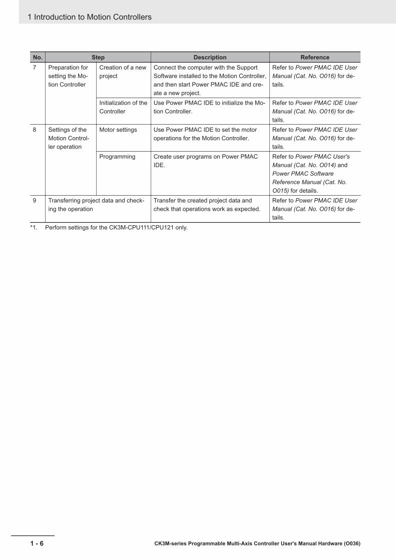
No. Step Description Reference7 Preparation for
setting the Mo-tion Controller
Creation of a newproject
Connect the computer with the SupportSoftware installed to the Motion Controller,and then start Power PMAC IDE and cre-ate a new project.
Refer to Power PMAC IDE UserManual (Cat. No. O016) for de-tails.
Initialization of theController
Use Power PMAC IDE to initialize the Mo-tion Controller.
Refer to Power PMAC IDE UserManual (Cat. No. O016) for de-tails.
8 Settings of theMotion Control-ler operation
Motor settings Use Power PMAC IDE to set the motoroperations for the Motion Controller.
Refer to Power PMAC IDE UserManual (Cat. No. O016) for de-tails.
Programming Create user programs on Power PMACIDE.
Refer to Power PMAC User'sManual (Cat. No. O014) andPower PMAC SoftwareReference Manual (Cat. No.O015) for details.
9 Transferring project data and check-ing the operation
Transfer the created project data andcheck that operations work as expected.
Refer to Power PMAC IDE UserManual (Cat. No. O016) for de-tails.
*1. Perform settings for the CK3M-CPU111/CPU121 only.
1 Introduction to Motion Controllers
1 - 6 CK3M-series Programmable Multi-Axis Controller User's Manual Hardware (O036)
2System Configuration
This section describes the basic system configuration used for CK3M-series MotionControllers.
2-1 Basic System Configuration ....................................................................... 2 - 22-1-1 CK3W Unit Configuration.............................................................................. 2 - 22-1-2 EtherCAT Network Configuration.................................................................. 2 - 3
2-2 Connecting to the Power PMAC IDE .......................................................... 2 - 42-3 Ethernet Network Configuration................................................................. 2 - 5
2 - 1CK3M-series Programmable Multi-Axis Controller User's Manual Hardware (O036)
2
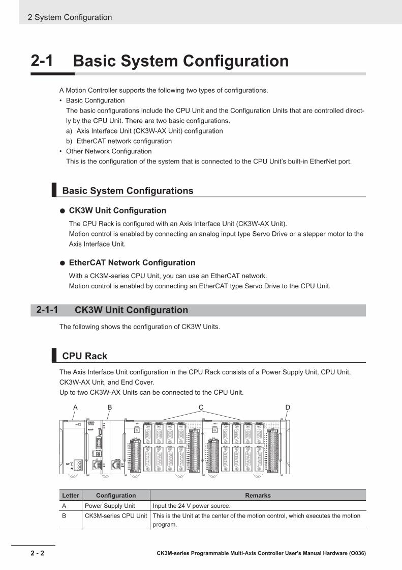
2-1 Basic System ConfigurationA Motion Controller supports the following two types of configurations.• Basic Configuration
The basic configurations include the CPU Unit and the Configuration Units that are controlled direct-ly by the CPU Unit. There are two basic configurations.a) Axis Interface Unit (CK3W-AX Unit) configurationb) EtherCAT network configuration
• Other Network ConfigurationThis is the configuration of the system that is connected to the CPU Unit’s built-in EtherNet port.
Basic System Configurations
CK3W Unit ConfigurationThe CPU Rack is configured with an Axis Interface Unit (CK3W-AX Unit).Motion control is enabled by connecting an analog input type Servo Drive or a stepper motor to theAxis Interface Unit.
EtherCAT Network ConfigurationWith a CK3M-series CPU Unit, you can use an EtherCAT network.Motion control is enabled by connecting an EtherCAT type Servo Drive to the CPU Unit.
2-1-1 CK3W Unit ConfigurationThe following shows the configuration of CK3W Units.
CPU RackThe Axis Interface Unit configuration in the CPU Rack consists of a Power Supply Unit, CPU Unit,CK3W-AX Unit, and End Cover.Up to two CK3W-AX Units can be connected to the CPU Unit.
IN0 1 2 3 4 5 6 7
8 9 10 11 12 13 14 15
0 1 2 3 4 5 6 7
8 9 10 11 12 13 14 15OUT
IN0 1 2 3 4 5 6 7
8 9 10 11 12 13 14 15
0 1 2 3 4 5 6 7
8 9 10 11 12 13 14 15OUT
A B C D
Letter Configuration RemarksA Power Supply Unit Input the 24 V power source.B CK3M-series CPU Unit This is the Unit at the center of the motion control, which executes the motion
program.
2 System Configuration
2 - 2 CK3M-series Programmable Multi-Axis Controller User's Manual Hardware (O036)

Letter Configuration RemarksC CK3W-AX Unit Axis Interface Unit. For axis control, connect the Servo Drive and Encoder.D End Cover Must be connected to the right end of the CPU Rack. One End Cover is pro-
vided with the CPU Unit.
2-1-2 EtherCAT Network ConfigurationThe EtherCAT network configuration consists of a Power Supply Unit, CPU Unit, End Cover, andEtherCAT slaves.Use the built-in EtherCAT port on the CK3M-series CPU Unit to connect EtherCAT slaves.
Slave terminal
EtherCAT slaves
Servo drive/Encoder input slaves
General-purpose slaves
EtherCAT is synchronized with the servo cycle of the CK3M-series CPU Unit. This enables acquisitionof the I/O data of slave terminals that are synchronized with the servo cycle.
2 System Configuration
2 - 3CK3M-series Programmable Multi-Axis Controller User's Manual Hardware (O036)
2-1 Basic System
Configuration
2
2-1-2 EtherCAT N
etwork C
onfiguration
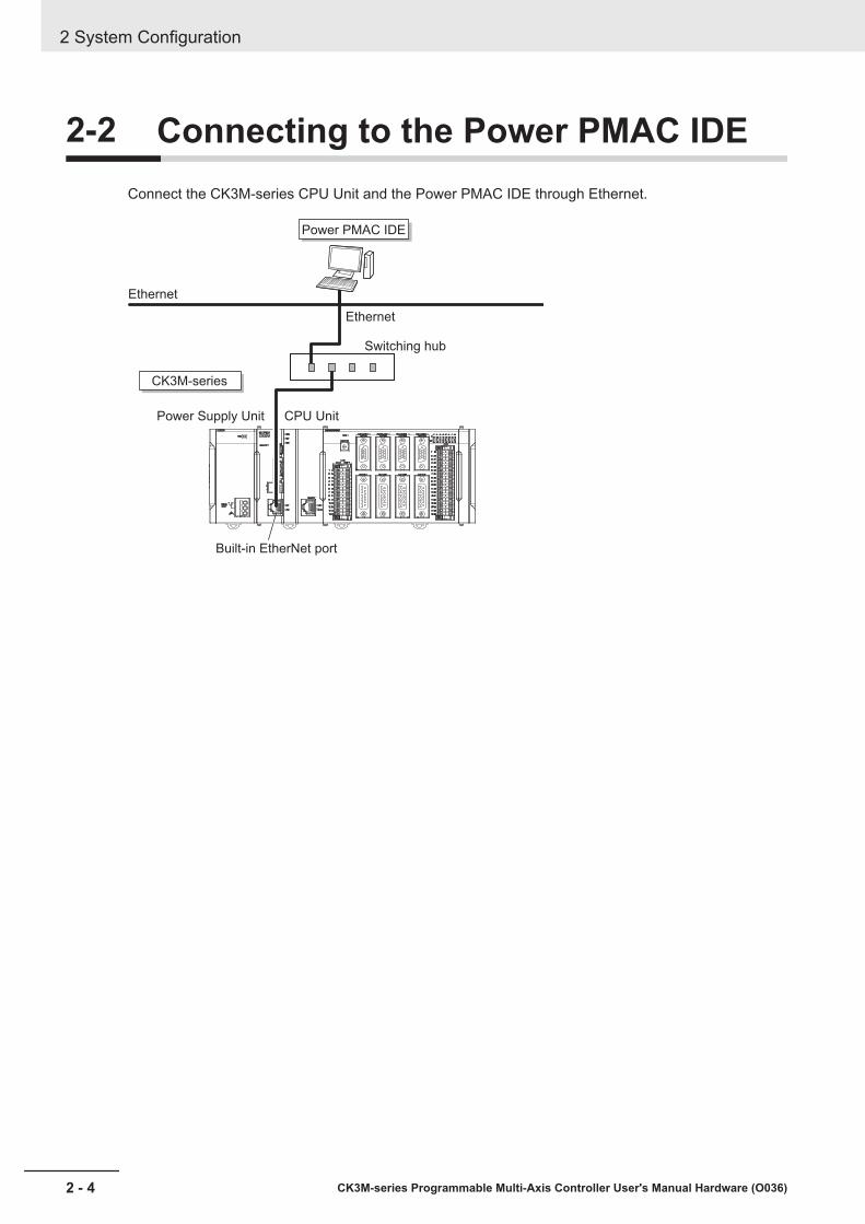
2-2 Connecting to the Power PMAC IDEConnect the CK3M-series CPU Unit and the Power PMAC IDE through Ethernet.
Power PMAC IDE
CK3M-series
Ethernet
Ethernet
Built-in EtherNet port
Power Supply Unit CPU Unit
Switching hub
2 System Configuration
2 - 4 CK3M-series Programmable Multi-Axis Controller User's Manual Hardware (O036)

2-3 Ethernet Network ConfigurationThe Ethernet communications port on the CK3M-series CPU Unit supports the Modbus-TCP protocol.It can be connected to devices such as PLCs and programmable terminals that support the Modbus-TCP protocol.
HMINJ-series
CK3M-series
Ethernet
Ethernet
Built-in Ethernet port
Power Supply Unit CPU Unit
Switching hub
2 System Configuration
2 - 5CK3M-series Programmable Multi-Axis Controller User's Manual Hardware (O036)
2-3 Ethernet Netw
ork Configuration
2

2 System Configuration
2 - 6 CK3M-series Programmable Multi-Axis Controller User's Manual Hardware (O036)
3Configuration Units
This section describes configuration devices in the CK3M-series Motion Controllerconfiguration.
3-1 CPU Unit........................................................................................................ 3 - 23-1-1 Models and Specifications ............................................................................ 3 - 23-1-2 Part Names and Functions ........................................................................... 3 - 43-1-3 Operation Status Indicators .......................................................................... 3 - 53-1-4 Watchdog Output Terminal Block.................................................................. 3 - 63-1-5 USB Memory Device .................................................................................... 3 - 7
3-2 Power Supply Unit........................................................................................ 3 - 93-2-1 Models and Specifications ............................................................................ 3 - 93-2-2 Part Names and Functions ......................................................................... 3 - 10
3-3 Axis Interface Unit...................................................................................... 3 - 113-3-1 Models and Specifications ...........................................................................3 - 113-3-2 Part Names and Functions ......................................................................... 3 - 123-3-3 Operation Status Indicators ........................................................................ 3 - 133-3-4 Address Switch Setting............................................................................... 3 - 133-3-5 Encoder Connector Specifications.............................................................. 3 - 143-3-6 Encoder Loss Detection in Digital Quadrature Encoder ............................. 3 - 183-3-7 Pulse Input Timing Specifications for Digital Quadrature Encoder ............. 3 - 193-3-8 OutFlag Function ........................................................................................ 3 - 203-3-9 Amplifier Connector Specifications ............................................................. 3 - 223-3-10 DA Output Method ...................................................................................... 3 - 253-3-11 Flag Connection Terminal Block Specifications .......................................... 3 - 263-3-12 General Digital I/O Connection Terminal Block Specifications ................... 3 - 30
3 - 1CK3M-series Programmable Multi-Axis Controller User's Manual Hardware (O036)
3
3-1 CPU UnitThis section describes the models and major specifications of the CK3M-series CPU Units.
3-1-1 Models and Specifications
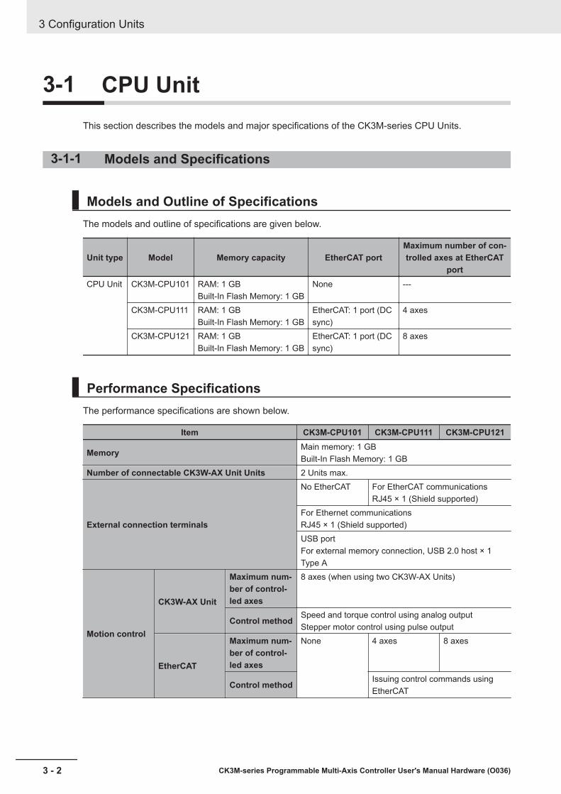
Models and Outline of SpecificationsThe models and outline of specifications are given below.
Unit type Model Memory capacity EtherCAT portMaximum number of con-trolled axes at EtherCAT
portCPU Unit CK3M-CPU101 RAM: 1 GB
Built-In Flash Memory: 1 GBNone ---
CK3M-CPU111 RAM: 1 GBBuilt-In Flash Memory: 1 GB
EtherCAT: 1 port (DCsync)
4 axes
CK3M-CPU121 RAM: 1 GBBuilt-In Flash Memory: 1 GB
EtherCAT: 1 port (DCsync)
8 axes
Performance SpecificationsThe performance specifications are shown below.
Item CK3M-CPU101 CK3M-CPU111 CK3M-CPU121
Memory Main memory: 1 GBBuilt-In Flash Memory: 1 GB
Number of connectable CK3W-AX Unit Units 2 Units max.
External connection terminals
No EtherCAT For EtherCAT communicationsRJ45 × 1 (Shield supported)
For Ethernet communicationsRJ45 × 1 (Shield supported)USB portFor external memory connection, USB 2.0 host × 1Type A
Motion control
CK3W-AX Unit
Maximum num-ber of control-led axes
8 axes (when using two CK3W-AX Units)
Control method Speed and torque control using analog outputStepper motor control using pulse output
EtherCAT
Maximum num-ber of control-led axes
None 4 axes 8 axes
Control method Issuing control commands usingEtherCAT
3 Configuration Units
3 - 2 CK3M-series Programmable Multi-Axis Controller User's Manual Hardware (O036)
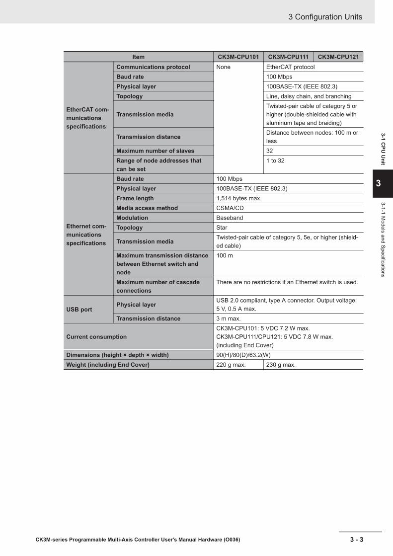
Item CK3M-CPU101 CK3M-CPU111 CK3M-CPU121
EtherCAT com-municationsspecifications
Communications protocol None EtherCAT protocolBaud rate 100 MbpsPhysical layer 100BASE-TX (IEEE 802.3)Topology Line, daisy chain, and branching
Transmission mediaTwisted-pair cable of category 5 orhigher (double-shielded cable withaluminum tape and braiding)
Transmission distance Distance between nodes: 100 m orless
Maximum number of slaves 32Range of node addresses thatcan be set
1 to 32
Ethernet com-municationsspecifications
Baud rate 100 MbpsPhysical layer 100BASE-TX (IEEE 802.3)Frame length 1,514 bytes max.Media access method CSMA/CDModulation BasebandTopology Star
Transmission media Twisted-pair cable of category 5, 5e, or higher (shield-ed cable)
Maximum transmission distancebetween Ethernet switch andnode
100 m
Maximum number of cascadeconnections
There are no restrictions if an Ethernet switch is used.
USB portPhysical layer USB 2.0 compliant, type A connector. Output voltage:
5 V, 0.5 A max.Transmission distance 3 m max.
Current consumptionCK3M-CPU101: 5 VDC 7.2 W max.CK3M-CPU111/CPU121: 5 VDC 7.8 W max.(including End Cover)
Dimensions (height × depth × width) 90(H)/80(D)/63.2(W)Weight (including End Cover) 220 g max. 230 g max.
3 Configuration Units
3 - 3CK3M-series Programmable Multi-Axis Controller User's Manual Hardware (O036)
3-1 CPU
Unit
3
3-1-1 Models and Specifications
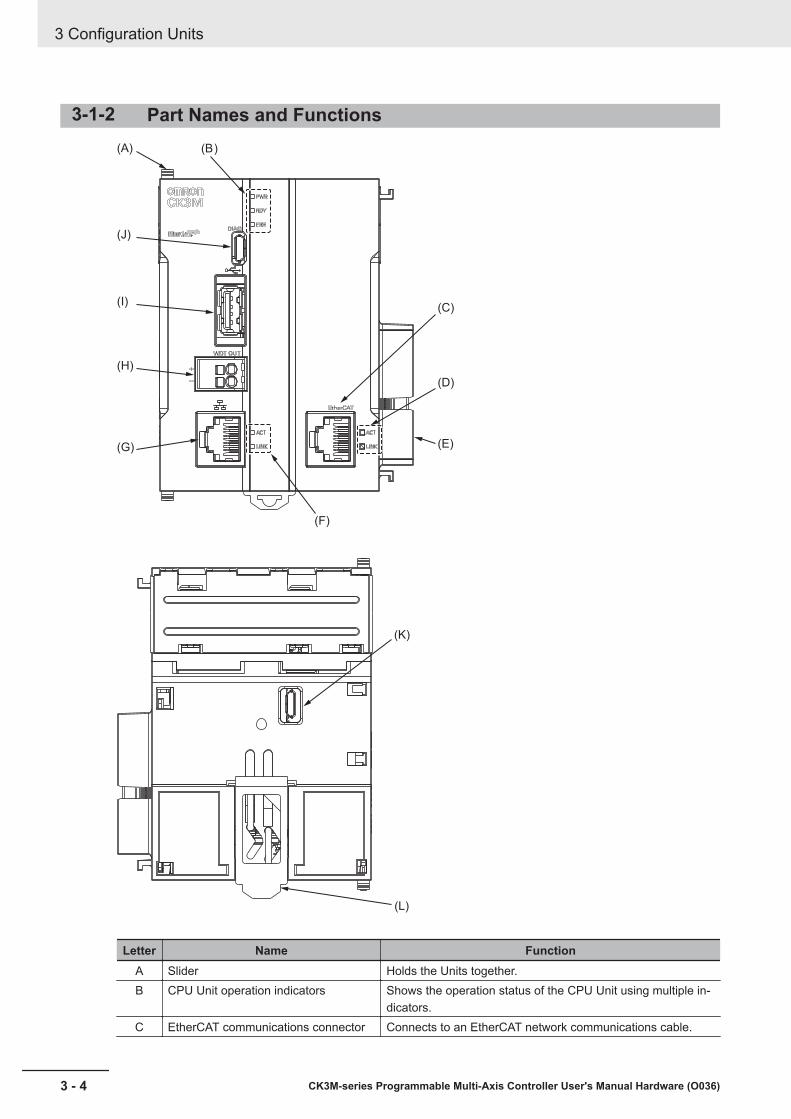
3-1-2 Part Names and Functions(A) (B)
(J)
(I)
(H)
(G)
(C)
(D)
(E)
(F)
(K)
(L)
Letter Name FunctionA Slider Holds the Units together.B CPU Unit operation indicators Shows the operation status of the CPU Unit using multiple in-
dicators.C EtherCAT communications connector Connects to an EtherCAT network communications cable.
3 Configuration Units
3 - 4 CK3M-series Programmable Multi-Axis Controller User's Manual Hardware (O036)

Letter Name FunctionD EtherCAT communications port opera-
tion indicatorsShows the operation status of EtherCAT.
E Unit connector Connector that connects to the Unit.F Ethernet communications port opera-
tion indicatorsShows the operation status of Ethernet.
G Ethernet communications connector Connects to an Ethernet network communications cable.H Watchdog output terminal block Normally in ON state, and switches to OFF when watchdog is
activated.I USB 2.0 connector USB 2.0 interface connector.
Connects the USB memory.J USB connector for maintenance Do not use.K USB connector for maintenance Do not use.L DIN Track mounting hook Used to mount the Unit to a DIN Track.
3-1-3 Operation Status Indicators
CPU Unit Operation Status IndicatorsThe CPU Unit is equipped with indicators to show the current operations status.
CPU Unit Status IndicatorsThe operating statuses corresponding to the colors and statuses of the indicators are shown below.
Indicator name Color Status DescriptionPWR Green Lit. Power is supplied to the Unit.
Not lit. Power is not supplied to the Unit.
3 Configuration Units
3 - 5CK3M-series Programmable Multi-Axis Controller User's Manual Hardware (O036)
3-1 CPU
Unit
3
3-1-3 Operation Status Indicators
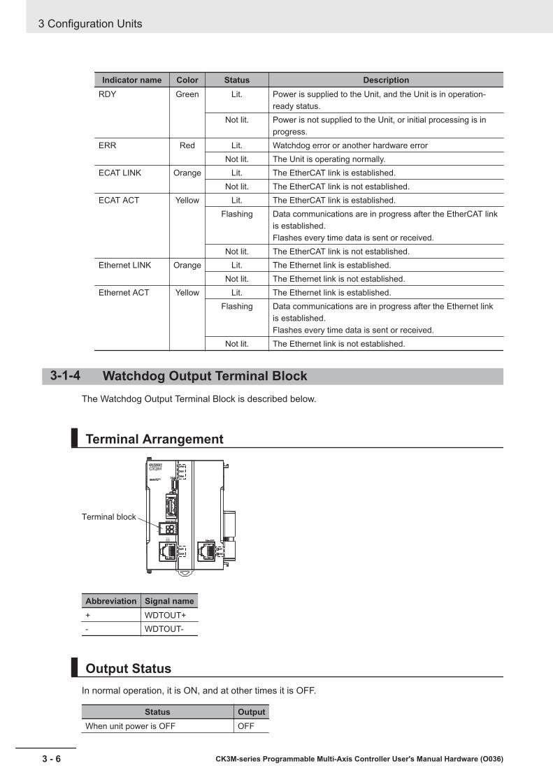
Indicator name Color Status DescriptionRDY Green Lit. Power is supplied to the Unit, and the Unit is in operation-
ready status.Not lit. Power is not supplied to the Unit, or initial processing is in
progress.ERR Red Lit. Watchdog error or another hardware error
Not lit. The Unit is operating normally.ECAT LINK Orange Lit. The EtherCAT link is established.
Not lit. The EtherCAT link is not established.ECAT ACT Yellow Lit. The EtherCAT link is established.
Flashing Data communications are in progress after the EtherCAT linkis established.Flashes every time data is sent or received.
Not lit. The EtherCAT link is not established.Ethernet LINK Orange Lit. The Ethernet link is established.
Not lit. The Ethernet link is not established.Ethernet ACT Yellow Lit. The Ethernet link is established.
Flashing Data communications are in progress after the Ethernet linkis established.Flashes every time data is sent or received.
Not lit. The Ethernet link is not established.
3-1-4 Watchdog Output Terminal BlockThe Watchdog Output Terminal Block is described below.
Terminal Arrangement
Terminal block
Abbreviation Signal name+ WDTOUT+- WDTOUT-
Output StatusIn normal operation, it is ON, and at other times it is OFF.
Status OutputWhen unit power is OFF OFF
3 Configuration Units
3 - 6 CK3M-series Programmable Multi-Axis Controller User's Manual Hardware (O036)
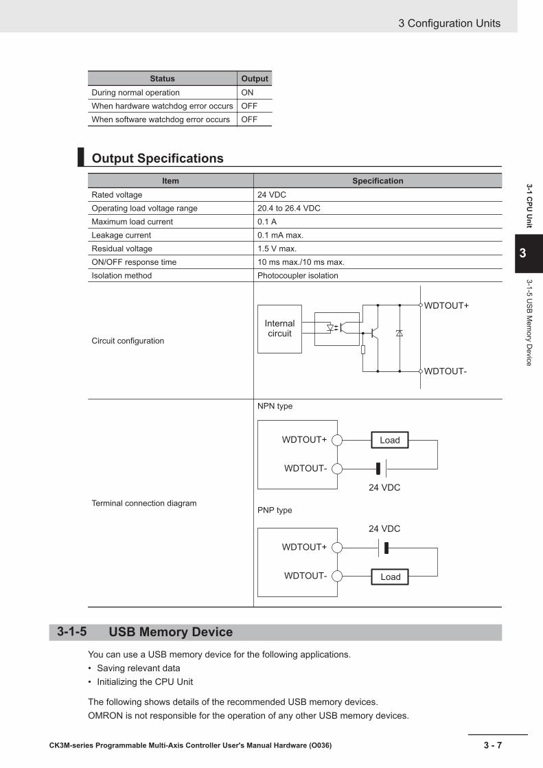
Status OutputDuring normal operation ONWhen hardware watchdog error occurs OFFWhen software watchdog error occurs OFF
Output SpecificationsItem Specification
Rated voltage 24 VDCOperating load voltage range 20.4 to 26.4 VDCMaximum load current 0.1 ALeakage current 0.1 mA max.Residual voltage 1.5 V max.ON/OFF response time 10 ms max./10 ms max.Isolation method Photocoupler isolation
Circuit configuration
WDTOUT+
WDTOUT-
Internal
circuit
Terminal connection diagram
NPN type
WDTOUT+
24 VDC
WDTOUT-
Load
PNP type
WDTOUT+
24 VDC
WDTOUT- Load
3-1-5 USB Memory DeviceYou can use a USB memory device for the following applications.• Saving relevant data• Initializing the CPU Unit
The following shows details of the recommended USB memory devices.OMRON is not responsible for the operation of any other USB memory devices.
3 Configuration Units
3 - 7CK3M-series Programmable Multi-Axis Controller User's Manual Hardware (O036)
3-1 CPU
Unit
3
3-1-5 USB M
emory D
evice

Recommended USB memories DescriptionFZ-MEM2G OMRON USB memory device (2 GB)FZ-MEM8G OMRON USB memory device (8 GB)
3 Configuration Units
3 - 8 CK3M-series Programmable Multi-Axis Controller User's Manual Hardware (O036)

3-2 Power Supply UnitThis section describes the model and major specifications of the Power Supply Unit.
3-2-1 Models and Specifications
Models and Outline of SpecificationsThe models and outline of specifications are given below.
Unit type Model SpecificationPower Supply Unit CK3W-PD048 Rated output voltage: 5 VDC/24 VDC
Maximum output power: 5 VDC 23 W, 24 VDC 66 W
SpecificationsThe specifications are shown below.
Item SpecificationPower supply voltage 24 VDCAllowable power supply voltagerange
20.4 to 26.4 VDC
Power consumption 101.7 W max.Rated output voltage 5 VDC/24 VDC
Maximum output power *15 VDC 23 W24 VDC 66 W
Isolation method Not isolated
Circuit configurationNoisefilter
circuit
DC-DCConverter
(Not isolated)
24 VDC input +
24 VDC input -
+5 VDC output
+24 VDC output
0 V
Weight 130 g max.Dimensions (height × depth × width) 90(H)/80(D)/45(W)
*1. Internal components in the Power Supply Unit may deteriorate or be damaged if the Power Supply Unit isused for an extended period of time exceeding the power supply output capacity or used when the outputsare shorted.
Recommended Power SuppliesUse a SELV power supply that meets the following conditions.• Has overcurrent protection.
3 Configuration Units
3 - 9CK3M-series Programmable Multi-Axis Controller User's Manual Hardware (O036)
3-2 Power Supply U
nit
3
3-2-1 Models and Specifications
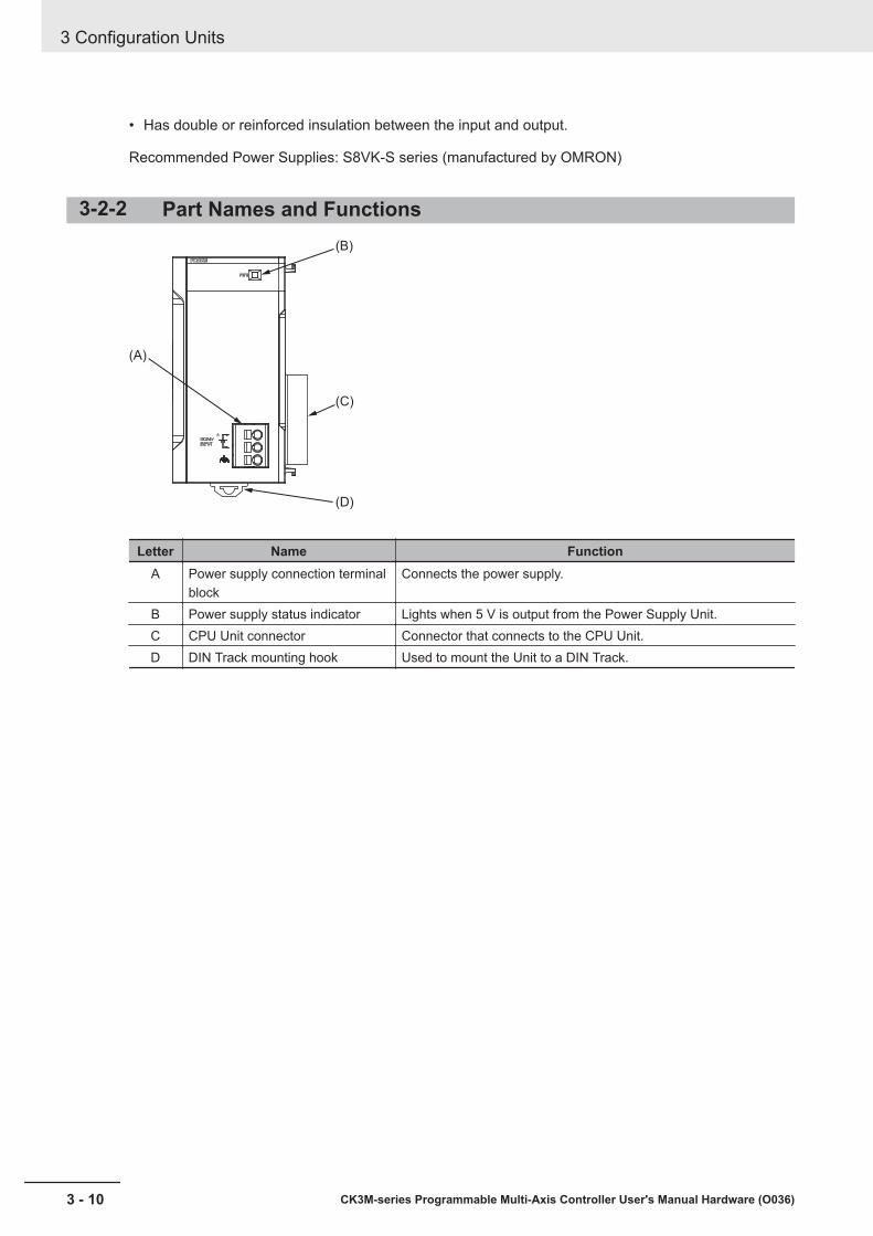
• Has double or reinforced insulation between the input and output.
Recommended Power Supplies: S8VK-S series (manufactured by OMRON)
3-2-2 Part Names and Functions(B)
(C)
(D)
(A)
Letter Name FunctionA Power supply connection terminal
blockConnects the power supply.
B Power supply status indicator Lights when 5 V is output from the Power Supply Unit.C CPU Unit connector Connector that connects to the CPU Unit.D DIN Track mounting hook Used to mount the Unit to a DIN Track.
3 Configuration Units
3 - 10 CK3M-series Programmable Multi-Axis Controller User's Manual Hardware (O036)
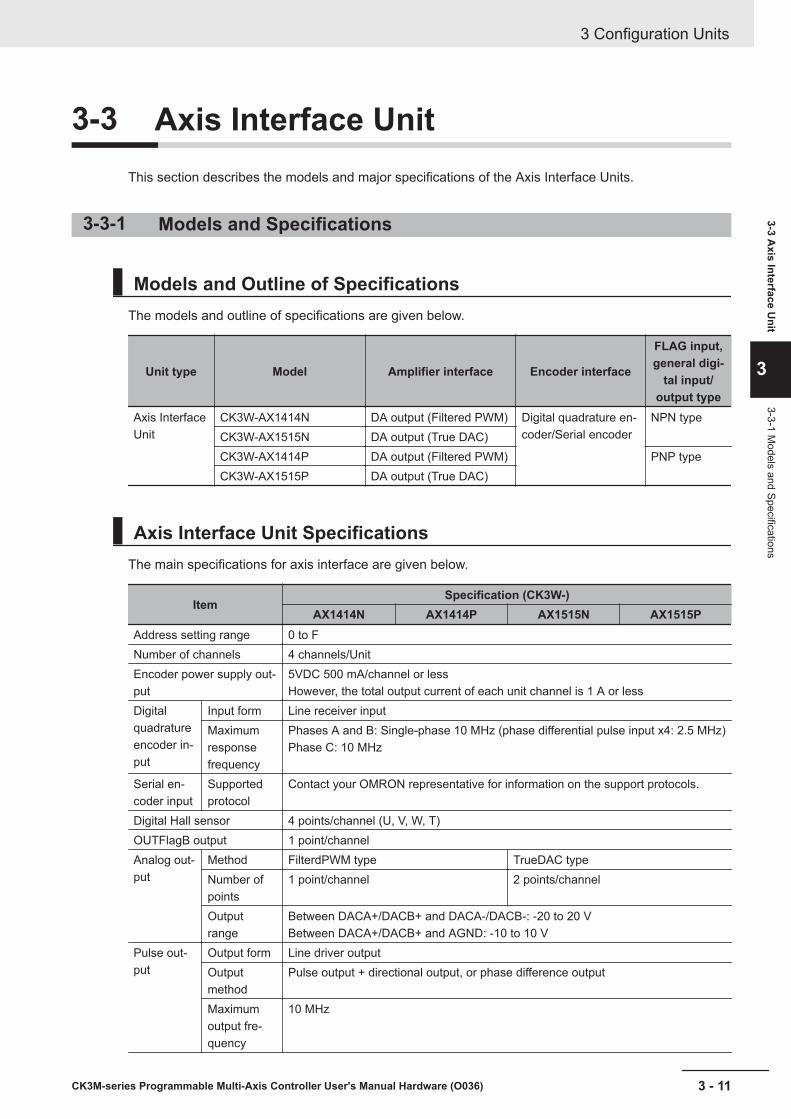
3-3 Axis Interface UnitThis section describes the models and major specifications of the Axis Interface Units.
3-3-1 Models and Specifications
Models and Outline of SpecificationsThe models and outline of specifications are given below.
Unit type Model Amplifier interface Encoder interface
FLAG input,general digi-
tal input/output type
Axis InterfaceUnit
CK3W-AX1414N DA output (Filtered PWM) Digital quadrature en-coder/Serial encoder
NPN typeCK3W-AX1515N DA output (True DAC)CK3W-AX1414P DA output (Filtered PWM) PNP typeCK3W-AX1515P DA output (True DAC)
Axis Interface Unit SpecificationsThe main specifications for axis interface are given below.
ItemSpecification (CK3W-)
AX1414N AX1414P AX1515N AX1515PAddress setting range 0 to FNumber of channels 4 channels/UnitEncoder power supply out-put
5VDC 500 mA/channel or lessHowever, the total output current of each unit channel is 1 A or less
Digitalquadratureencoder in-put
Input form Line receiver inputMaximumresponsefrequency
Phases A and B: Single-phase 10 MHz (phase differential pulse input x4: 2.5 MHz)Phase C: 10 MHz
Serial en-coder input
Supportedprotocol
Contact your OMRON representative for information on the support protocols.
Digital Hall sensor 4 points/channel (U, V, W, T)OUTFlagB output 1 point/channelAnalog out-put
Method FilterdPWM type TrueDAC typeNumber ofpoints
1 point/channel 2 points/channel
Outputrange
Between DACA+/DACB+ and DACA-/DACB-: -20 to 20 VBetween DACA+/DACB+ and AGND: -10 to 10 V
Pulse out-put
Output form Line driver outputOutputmethod
Pulse output + directional output, or phase difference output
Maximumoutput fre-quency
10 MHz
3 Configuration Units
3 - 11CK3M-series Programmable Multi-Axis Controller User's Manual Hardware (O036)
3-3 Axis Interface U
nit
3
3-3-1 Models and Specifications

ItemSpecification (CK3W-)
AX1414N AX1414P AX1515N AX1515PAmp enable output 1 point/channelFault input 1 point/channelFlags Digital input 4 points/channel (HOME, PLIM, NLIM, USER)
Digital out-put
1 point/channel (EQU)
Generaldigital I/O
Number ofpoints
16 inputs, 16 outputs
Internalcommon
NPN PNP NPN PNP
Current consumption 5 VDC: 4.5 W max.24 VDC: 10.8 W max.
5 VDC: 4.5 W max.24 VDC: 12.5 W max.
Dimensions (height ×depth × width)
90(H)/80(D)/130(W)
Weight 520 g max.
3-3-2 Part Names and Functions
(F)
(G)
(H)(I)
(J)
(K)
(A) (B) (C) (D) (E)
IN0 1 2 3 4 5 6 7
8 9 10 11 12 13 14 15
0 1 2 3 4 5 6 7
8 9 10 11 12 13 14 15OUT
Letter Name FunctionA Slider Holds the Units together.B Power supply status indicator Shows the power supply status.C Amp enable status indicator Shows the Amp enable status.D Encoder connector Connects the encoder.E General digital input/output status
indicatorShows the general digital input/output status.
F General digital input/output con-nection terminal block
Connects the general digital input/output.
G Unit connector Connector that connects to the Unit.H Amplifier connector Connects the amplifier.
3 Configuration Units
3 - 12 CK3M-series Programmable Multi-Axis Controller User's Manual Hardware (O036)
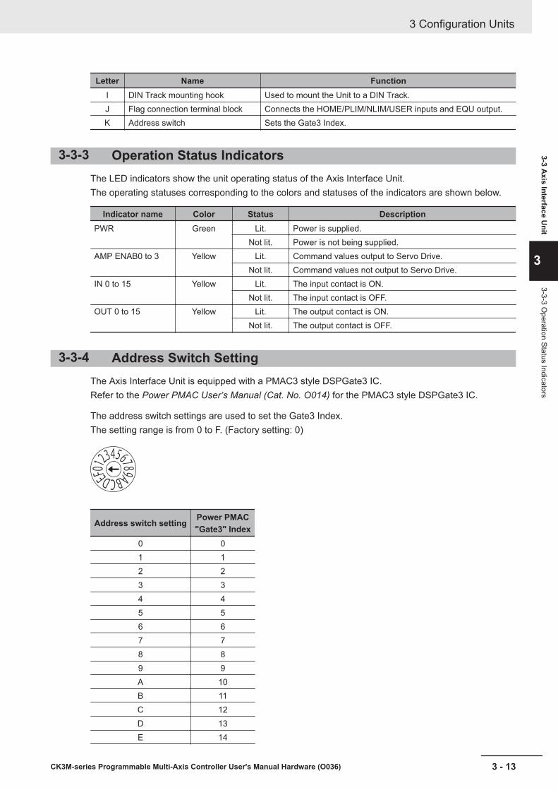
Letter Name FunctionI DIN Track mounting hook Used to mount the Unit to a DIN Track.J Flag connection terminal block Connects the HOME/PLIM/NLIM/USER inputs and EQU output.K Address switch Sets the Gate3 Index.
3-3-3 Operation Status IndicatorsThe LED indicators show the unit operating status of the Axis Interface Unit.The operating statuses corresponding to the colors and statuses of the indicators are shown below.
Indicator name Color Status DescriptionPWR Green Lit. Power is supplied.
Not lit. Power is not being supplied.AMP ENAB0 to 3 Yellow Lit. Command values output to Servo Drive.
Not lit. Command values not output to Servo Drive.IN 0 to 15 Yellow Lit. The input contact is ON.
Not lit. The input contact is OFF.OUT 0 to 15 Yellow Lit. The output contact is ON.
Not lit. The output contact is OFF.
3-3-4 Address Switch SettingThe Axis Interface Unit is equipped with a PMAC3 style DSPGate3 IC.Refer to the Power PMAC User’s Manual (Cat. No. O014) for the PMAC3 style DSPGate3 IC.
The address switch settings are used to set the Gate3 Index.The setting range is from 0 to F. (Factory setting: 0)
Address switch setting Power PMAC"Gate3" Index
0 01 12 23 34 45 56 67 78 89 9A 10B 11C 12D 13E 14
3 Configuration Units
3 - 13CK3M-series Programmable Multi-Axis Controller User's Manual Hardware (O036)
3-3 Axis Interface U
nit
3
3-3-3 Operation Status Indicators
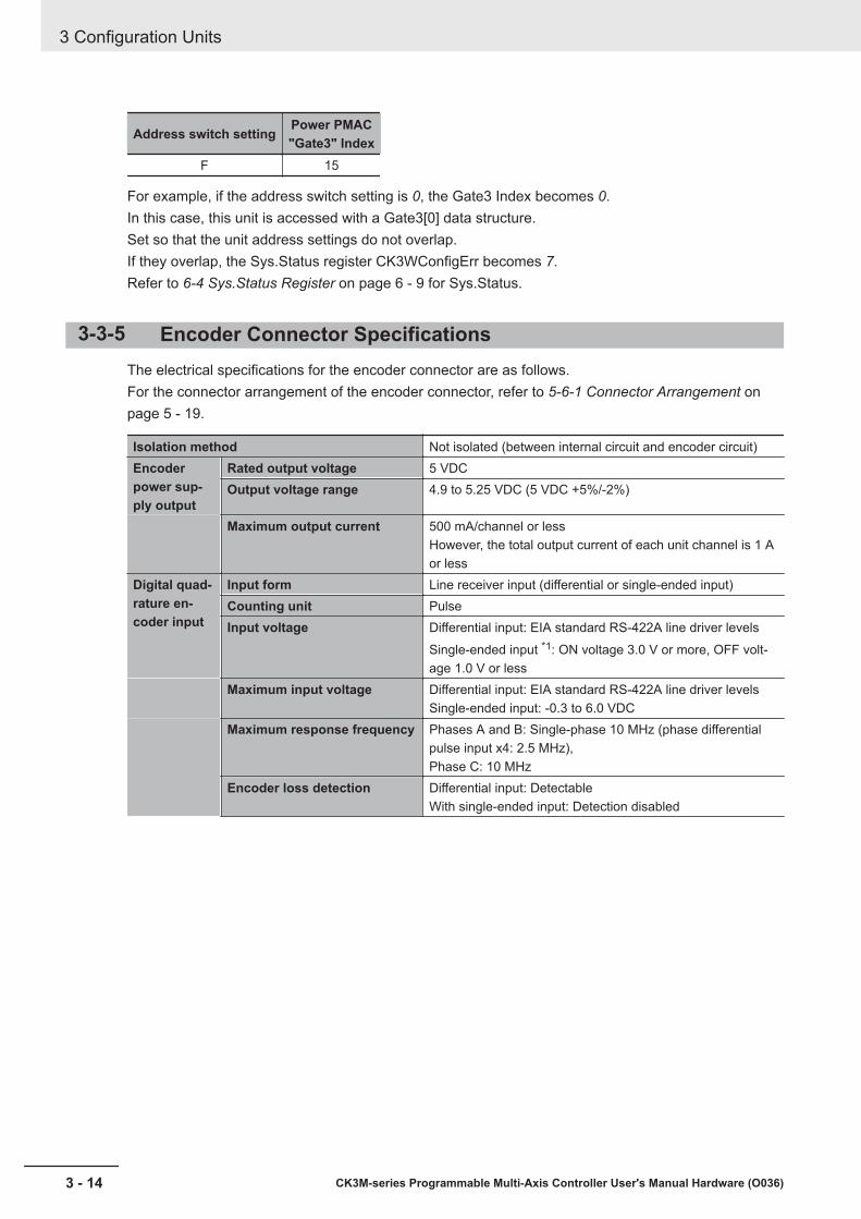
Address switch setting Power PMAC"Gate3" Index
F 15
For example, if the address switch setting is 0, the Gate3 Index becomes 0.In this case, this unit is accessed with a Gate3[0] data structure.Set so that the unit address settings do not overlap.If they overlap, the Sys.Status register CK3WConfigErr becomes 7.Refer to 6-4 Sys.Status Register on page 6 - 9 for Sys.Status.
3-3-5 Encoder Connector SpecificationsThe electrical specifications for the encoder connector are as follows.For the connector arrangement of the encoder connector, refer to 5-6-1 Connector Arrangement onpage 5 - 19.
Isolation method Not isolated (between internal circuit and encoder circuit)Encoderpower sup-ply output
Rated output voltage 5 VDCOutput voltage range 4.9 to 5.25 VDC (5 VDC +5%/-2%)
Maximum output current 500 mA/channel or lessHowever, the total output current of each unit channel is 1 Aor less
Digital quad-rature en-coder input
Input form Line receiver input (differential or single-ended input)Counting unit PulseInput voltage Differential input: EIA standard RS-422A line driver levels
Single-ended input *1: ON voltage 3.0 V or more, OFF volt-age 1.0 V or less
Maximum input voltage Differential input: EIA standard RS-422A line driver levelsSingle-ended input: -0.3 to 6.0 VDC
Maximum response frequency Phases A and B: Single-phase 10 MHz (phase differentialpulse input x4: 2.5 MHz),Phase C: 10 MHz
Encoder loss detection Differential input: DetectableWith single-ended input: Detection disabled
3 Configuration Units
3 - 14 CK3M-series Programmable Multi-Axis Controller User's Manual Hardware (O036)
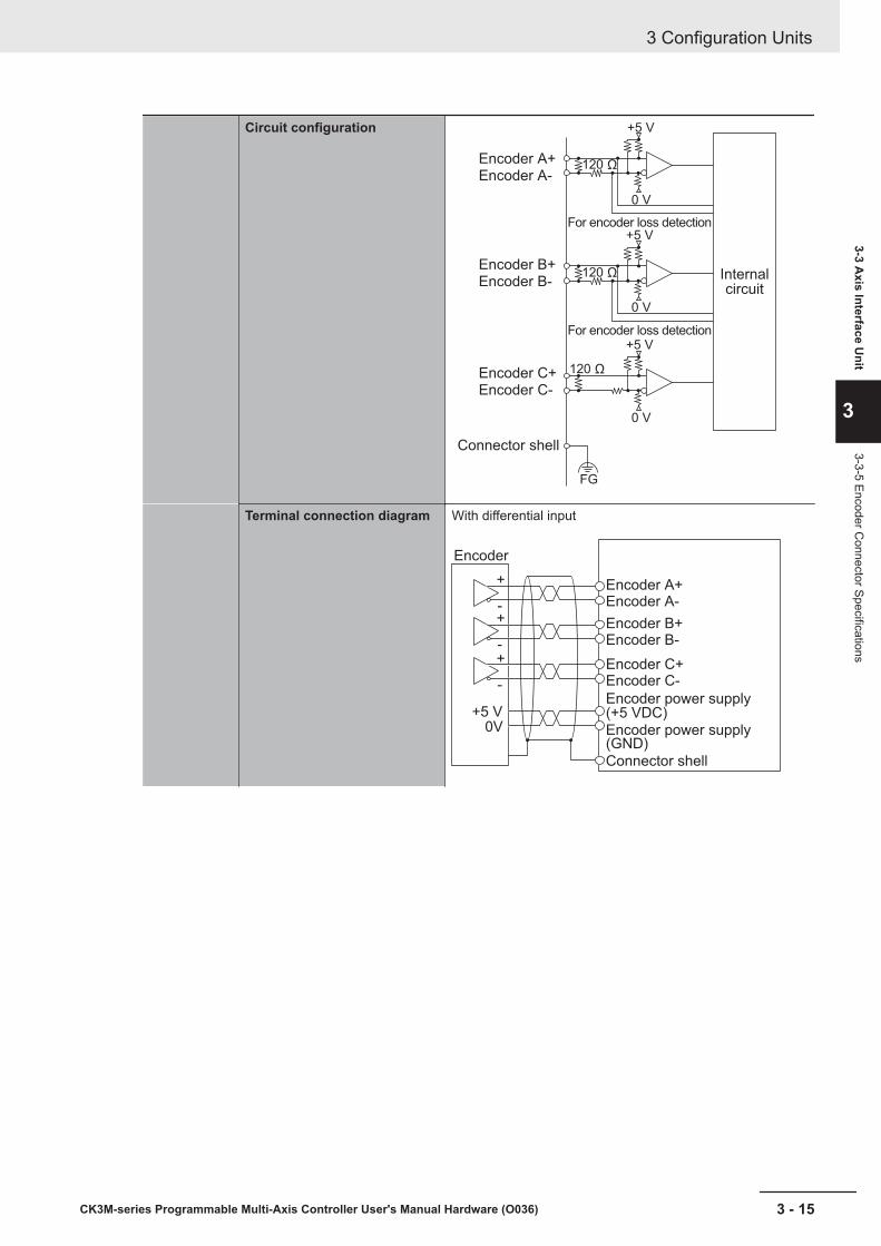
Circuit configuration
Encoder A+
Encoder A-
Internal
circuit
For encoder loss detection
For encoder loss detection
120 Ω
120 Ω
120 Ω
+5 V
+5 V
0 V
0 V
+5 V
0 V
Encoder B+
Encoder B-
Encoder C+
Encoder C-
Connector shell
FG
Terminal connection diagram With differential input
Encoder
Encoder A+Encoder A-
Encoder B+Encoder B-
Encoder C+Encoder C-
Encoder power supply(+5 VDC)Encoder power supply(GND)
Connector shell
+5 V0V
+
-+
-+
-
3 Configuration Units
3 - 15CK3M-series Programmable Multi-Axis Controller User's Manual Hardware (O036)
3-3 Axis Interface U
nit
3
3-3-5 Encoder Connector Specifications
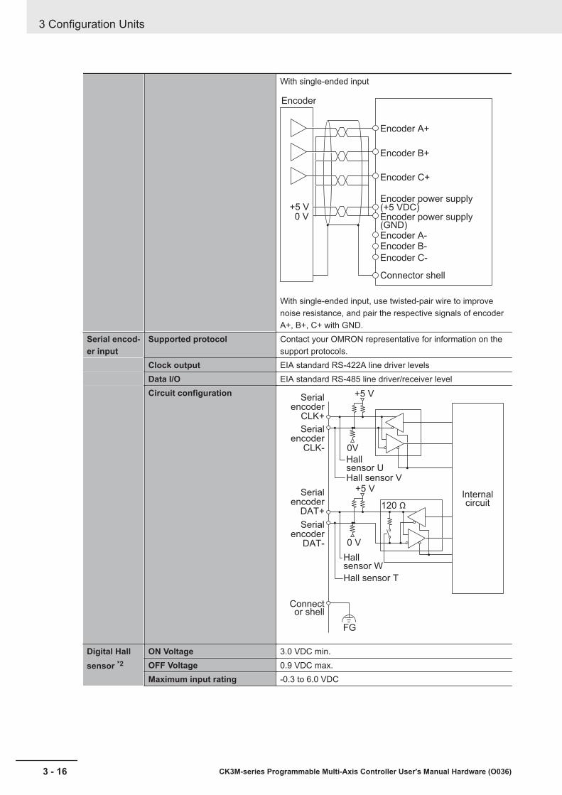
With single-ended input
Encoder
Encoder A+
Encoder A-Encoder B-
Encoder C-
Encoder B+
Encoder C+
(+5 VDC)Encoder power supply
Encoder power supply(GND)
Connector shell
+5 V0 V
With single-ended input, use twisted-pair wire to improvenoise resistance, and pair the respective signals of encoderA+, B+, C+ with GND.
Serial encod-er input
Supported protocol Contact your OMRON representative for information on thesupport protocols.
Clock output EIA standard RS-422A line driver levelsData I/O EIA standard RS-485 line driver/receiver levelCircuit configuration
Serial
encoder
CLK+
Serial
encoder
CLK-
Serial
encoder
DAT+
Serial
encoder
DAT-
Connector shell
Hall sensor T
Hall sensor V
Hallsensor W
Hallsensor U
Internal circuit
+5 V
+5 V
120 Ω
0V
0 V
FG
Digital Hallsensor *2
ON Voltage 3.0 VDC min.OFF Voltage 0.9 VDC max.Maximum input rating -0.3 to 6.0 VDC
3 Configuration Units
3 - 16 CK3M-series Programmable Multi-Axis Controller User's Manual Hardware (O036)
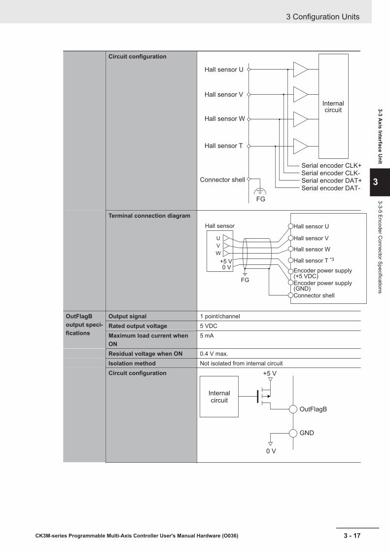
Circuit configuration
Serial encoder CLK+
Serial encoder CLK-
Serial encoder DAT+
Serial encoder DAT-
FG
Hall sensor U
Hall sensor V
Hall sensor W
Hall sensor T
Connector shell
Internal
circuit
Terminal connection diagram
U
+5 V0 V
FG
V
W
Hall sensor Hall sensor U
Hall sensor V
Hall sensor W
Hall sensor T *3
Encoder power supply(+5 VDC)Encoder power supply(GND)Connector shell
OutFlagBoutput speci-fications
Output signal 1 point/channelRated output voltage 5 VDCMaximum load current whenON
5 mA
Residual voltage when ON 0.4 V max.Isolation method Not isolated from internal circuitCircuit configuration +5 V
OutFlagB
GND
0 V
Internal circuit
3 Configuration Units
3 - 17CK3M-series Programmable Multi-Axis Controller User's Manual Hardware (O036)
3-3 Axis Interface U
nit
3
3-3-5 Encoder Connector Specifications

Connection diagram
Connector shell
OutFlagB
GND
For the GND, use an encoder power source (GND).*1. With single-ended input, only a voltage output type encoder can be connected. Open collector type encod-
ers cannot be connected.*2. A Hall sensor is a sensor that detects the rotor position of the motor by detecting the magnetic field. This is
normally used to check the position when the power is turned ON.*3. HALL T is not normally used, however, it can be used as a general 5V digital input.
3-3-6 Encoder Loss Detection in Digital Quadrature EncoderEncoder loss detection is a function for detecting the encoder detachment. It can detect the encoderloss, and stop the motor.
In the differential input for the digital quadrature encoder, when a correct signal arrives in encoder A+/A-, encoder B+/B-, if the signal level is H in one side, the signal level of the other side is always L.
L
H
L
H
L
H
H
L
H
L
Encoder A+/B+
Encoder A-/B-
You can detect the encoder loss by setting a circuit so that both signals turn H or L when the encoderis not connected.
Encoder A+/B+ Encoder A-/B- Encoder loss detectionH L NormalL H NormalH H Detects lossL L Detects loss
If loss is detected, the value of Gate3[i].Chan[j].LossStatus becomes 1.Motor[x].EncLossCount adds 1 to the count when encoder loss is detected, and subtracts 1 when en-coder loss is not detected.However, the minimum value of Motor[x].EncLossCount is 0, and it will never become a negative val-ue.You can set the motor to stop if Motor[x].EncLossCount exceeds the value set in theMotor[x].EncLossLimit. However, in a pulse input state, mis-detection of encoder loss may occur.Therefore, when you use the function to stop the motor at encoder loss, take the possibility of mis-detection during pulse input into consideration, and set the Motor[x].EncLossLimit register to 40 ormore.
3 Configuration Units
3 - 18 CK3M-series Programmable Multi-Axis Controller User's Manual Hardware (O036)
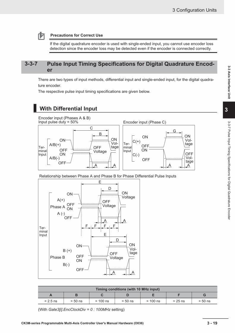
Precautions for Correct Use
If the digital quadrature encoder is used with single-ended input, you cannot use encoder lossdetection since the encoder loss may be detected even if the encoder is connected correctly.
3-3-7 Pulse Input Timing Specifications for Digital Quadrature Encod-er
There are two types of input methods, differential input and single-ended input, for the digital quadra-ture encoder.The respective pulse input timing specifications are given below.
With Differential Input
C
B
ONVol-tage
Vol-tage
Vol-tage
Vol-tage
OFF
ON
ONA/B(+)
A/B(-)
OFF
OFF
Encoder input (Phases A & B)Input pulse duty = 50%
VoltageTer-minalInput
Ter-minalInput
Ter-minalInput
E
D
ON
A A
F FFF
Voltage
OFF
ON
ON
A(+)
A (-)
OFF
OFF
Voltage
G
ON
OFFON
ONC(+)
C(-)
OFF
OFF
Encoder input (Phase C)
Relationship between Phase A and Phase B for Phase Differential Pulse Inputs
Phase A
Phase B
E
D
ON
OFF
ON
ON
B (+)
B(-)
OFF
OFF
Voltage
A A
A A AA
Timing conditions (with 10 MHz input)A B C D E F G
< 2.5 ns > 50 ns > 100 ns > 50 ns > 100 ns > 25 ns > 50 ns
(With Gate3[i].EncClockDiv = 0 : 100MHz setting)
3 Configuration Units
3 - 19CK3M-series Programmable Multi-Axis Controller User's Manual Hardware (O036)
3-3 Axis Interface U
nit
3
3-3-7 Pulse Input Timing Specifications for D
igital Quadrature Encoder
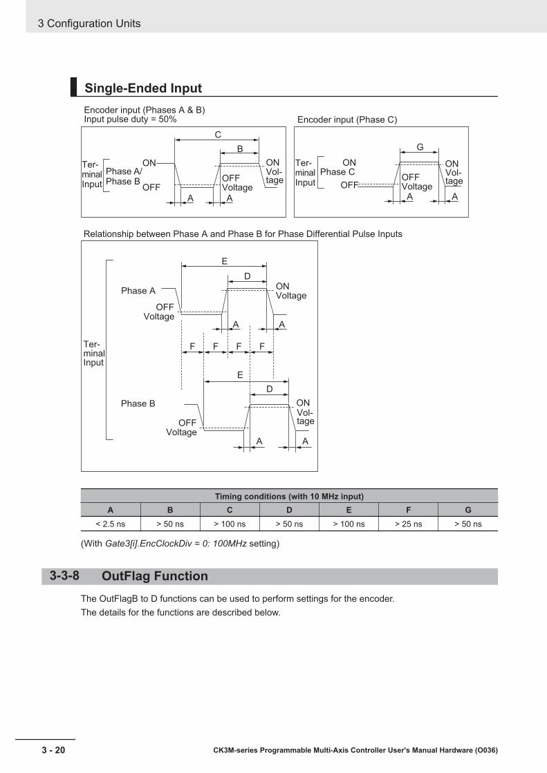
Single-Ended Input
C
GB
Phase A/Phase B
ON
OFF
ON
OFFOFFVoltage
OFFVoltage
ONONVol-tage
Vol-tage
Encoder input (Phases A & B)Input pulse duty = 50% Encoder input (Phase C)
Ter-minalInput
Ter-minalInput
Phase C
Ter-minalInput
D
E
ON
A A
AA
FFFF
Voltage
OFFVoltage
OFFVoltage
Relationship between Phase A and Phase B for Phase Differential Pulse Inputs
Phase A
Phase B
E
D
ON
A A A A
Vol-tage
Timing conditions (with 10 MHz input)A B C D E F G
< 2.5 ns > 50 ns > 100 ns > 50 ns > 100 ns > 25 ns > 50 ns
(With Gate3[i].EncClockDiv = 0: 100MHz setting)
3-3-8 OutFlag FunctionThe OutFlagB to D functions can be used to perform settings for the encoder.The details for the functions are described below.
3 Configuration Units
3 - 20 CK3M-series Programmable Multi-Axis Controller User's Manual Hardware (O036)

OutFlagB Function
ApplicationsUse this function as a signal to connect with the SEN signal that is necessary to acquire the abso-lute encoder value when connecting with the OMRON G5-series Servo Drives with General-purpose Pulse Train or Analog Inputs.
Details on the FunctionYou can switch the output transistor state of the 15-pin of the encoder connector by manipulatingthe Gate3[i].Chan[j].OutFlagB register.
Register value Output transistor status0 (Default) OFF1 ON
OutFlagC Function
ApplicationsUse this function when a servo clock signal must be output externally for synchronization with otherdevices.
Details on the FunctionYou can switch the serial encoder CLK+/- signal to the servo clock signal by manipulating theGate3[i].Chan[j].OutFlagC register.
Register value Signal level0 (Default) Serial encoder CLK+/- signal1 Servo clock +/- signal
OutFlagD Function
ApplicationsWhen connecting with the OMRON G5-series Servo Drives with General-purpose Pulse Train orAnalog Inputs, the encoder A+/- terminal and the serial encoder DAT+/- terminal are short circuitedand used to enable obtaining the absolute encoder value sent from the Servo Drive.Use this function to disable the terminating resistance of the serial encoder DAT+/- terminal, be-cause the terminating resistances of the short-circuited encoder A+/- terminal and the serial encod-er DAT +/- terminal overlap.
Details on the FunctionYou can enable or disable the terminating resistance of the serial encoder DAT+/- terminal asshown in the table below by setting the Gate3[i].Chan[j].OutFlagD register and theGate3[i].Chan[j].SerialEncEna register, which is for switching between enabling and disabling theserial encoder.
3 Configuration Units
3 - 21CK3M-series Programmable Multi-Axis Controller User's Manual Hardware (O036)
3-3 Axis Interface U
nit
3
3-3-8 OutFlag Function
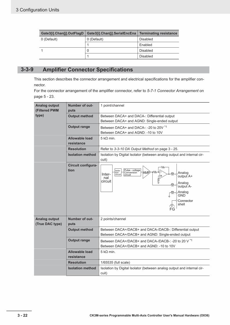
Gate3[i].Chan[j].OutFlagD Gate3[i].Chan[j].SerialEncEna Terminating resistance0 (Default) 0 (Default) Disabled
1 Enabled1 0 Disabled
1 Disabled
3-3-9 Amplifier Connector SpecificationsThis section describes the connector arrangement and electrical specifications for the amplifier con-nector.For the connector arrangement of the amplifier connector, refer to 5-7-1 Connector Arrangement onpage 5 - 23.
Analog output(Filtered PWMtype)
Number of out-puts
1 point/channel
Output method Between DACA+ and DACA-: Differential outputBetween DACA+ and AGND: Single-ended output
Output range Between DACA+ and DACA-: -20 to 20V *1
Between DACA+ and AGND: -10 to 10VAllowable loadresistance
5 kΩ min.
Resolution Refer to 3-3-10 DA Output Method on page 3 - 25.Isolation method Isolation by Digital Isolator (between analog output and internal cir-
cuit)Circuit configura-tion -
+AMP
FG
Pulse - voltageConversion circuitInter-
nal circuit
Isola-tion circuit
Analogoutput A+
Analogoutput A-
AnalogGND
Connectorshell
Analog output(True DAC type)
Number of out-puts
2 points/channel
Output method Between DACA+/DACB+ and DACA-/DACB-: Differential outputBetween DACA+/DACB+ and AGND: Single-ended output
Output range Between DACA+/DACB+ and DACA-/DACB-: -20 to 20 V *1
Between DACA+/DACB+ and AGND: -10 to 10VAllowable loadresistance
5 kΩ min.
Resolution 1/65535 (full scale)Isolation method Isolation by Digital Isolator (between analog output and internal cir-
cuit)
3 Configuration Units
3 - 22 CK3M-series Programmable Multi-Axis Controller User's Manual Hardware (O036)

Circuit configura-tion
Inter-nal
circuit
DAConverter
DAConverter
Iso-la
tion cir-cuit
Analogoutput A+
Analogoutput B+
Analogoutput B-
AnalogGNDConnectorshell
Analogoutput A-
-
+
-
+
AMP
AMP
FG
Pulse output Output signal Output: 2 points/channelPulse outputmethod
Pulse output + directional output, or phase difference output
Pulse outputform
Line driver output
Output voltage EIA standard RS-422A line driver levelsMaximum outputfrequency
10 MHz
Cable length 10 m max.Isolation method Not isolated from internal circuitCircuit configura-tion
Internal
circuit
Pulse output +
Directional output +
Directional output -
Connector shell
FG
0 V
GND
Pulse output -
Amp enable out-put
Number of out-puts
1 point/channel
Output method Relay output (N.O. + N.C.)Maximum switch-ing capacity
24 VDC/0.5 A
Minimum switch-ing capacity
5 VDC, 1 mA
Relay service life 100,000 operationsON/OFF re-sponse time
10 ms max./10 ms max.
Isolation method Isolation by Relay (between amp enable output and internal circuit)
3 Configuration Units
3 - 23CK3M-series Programmable Multi-Axis Controller User's Manual Hardware (O036)
3-3 Axis Interface U
nit
3
3-3-9 Amplifier C
onnector Specifications

Circuit configura-tion
Internal circuit
Amp enable NO
Amp enable common
Amp enable NC
Fault input Number of inputs 1 point/channelRated input volt-age
5 to 24 VDC
Maximum inputvoltage
26.4 VDC
Input current 7 mA typical (24 VDC)ON voltage/ONcurrent
3 VDC min./1 mA min.
OFF current 0.1 mA max.ON/OFF re-sponse time
20 μs min./400 μs max.
Isolation method Isolation by Photocoupler (between fault input and internal circuit)Circuit configura-tion
Fault input +
Internal circuit
Fault input -Current
control circuit
*1. In DACA-, the reversed voltage of the DACA+ is output. In other words, when DACA+ = +10 V, then DACA-= -10 V. In this case, between DACA+ and DACA-, a 20 V potential difference is generated. The same ap-plies to DACB+/DACB-.
3 Configuration Units
3 - 24 CK3M-series Programmable Multi-Axis Controller User's Manual Hardware (O036)
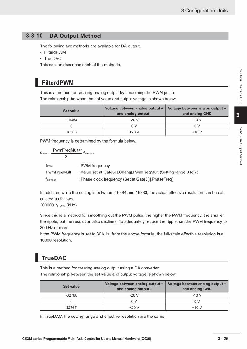
3-3-10 DA Output MethodThe following two methods are available for DA output.• FilterdPWM• TrueDACThis section describes each of the methods.
FilterdPWMThis is a method for creating analog output by smoothing the PWM pulse.The relationship between the set value and output voltage is shown below.
Set value Voltage between analog output +and analog output -
Voltage between analog output +and analog GND
-16384 -20 V -10 V0 0 V 0 V
16383 +20 V +10 V
PWM frequency is determined by the formula below.
fPWM
fPWM
PwmFreqMult
fIntPhase
fIntPhase
PwmFreqMult+1
2=
:PWM frequency
:Value set at Gate3[i].Chan[j].PwmFreqMult (Setting range 0 to 7)
:Phase clock frequency (Set at Gate3[i].PhaseFreq)
In addition, while the setting is between -16384 and 16383, the actual effective resolution can be cal-culated as follows.300000÷fPWM (kHz)
Since this is a method for smoothing out the PWM pulse, the higher the PWM frequency, the smallerthe ripple, but the resolution also declines. To adequately reduce the ripple, set the PWM frequency to30 kHz or more.If the PWM frequency is set to 30 kHz, from the above formula, the full-scale effective resolution is a10000 resolution.
TrueDACThis is a method for creating analog output using a DA converter.The relationship between the set value and output voltage is shown below.
Set value Voltage between analog output +and analog output -
Voltage between analog output +and analog GND
-32768 -20 V -10 V0 0 V 0 V
32767 +20 V +10 V
In TrueDAC, the setting range and effective resolution are the same.
3 Configuration Units
3 - 25CK3M-series Programmable Multi-Axis Controller User's Manual Hardware (O036)
3-3 Axis Interface U
nit
3
3-3-10 DA O
utput Method
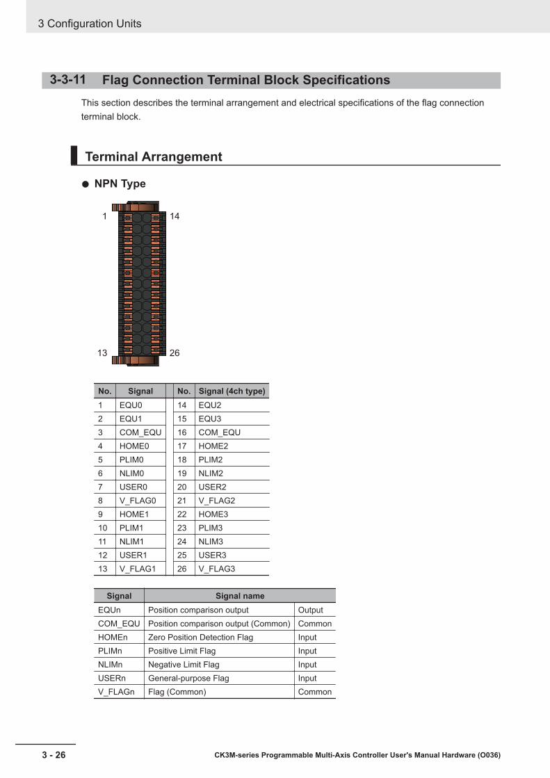
3-3-11 Flag Connection Terminal Block SpecificationsThis section describes the terminal arrangement and electrical specifications of the flag connectionterminal block.
Terminal Arrangement
NPN Type
1
13
14
26
No. Signal No. Signal (4ch type)1 EQU0 14 EQU22 EQU1 15 EQU33 COM_EQU 16 COM_EQU4 HOME0 17 HOME25 PLIM0 18 PLIM26 NLIM0 19 NLIM27 USER0 20 USER28 V_FLAG0 21 V_FLAG29 HOME1 22 HOME310 PLIM1 23 PLIM311 NLIM1 24 NLIM312 USER1 25 USER313 V_FLAG1 26 V_FLAG3
Signal Signal nameEQUn Position comparison output OutputCOM_EQU Position comparison output (Common) CommonHOMEn Zero Position Detection Flag InputPLIMn Positive Limit Flag InputNLIMn Negative Limit Flag InputUSERn General-purpose Flag InputV_FLAGn Flag (Common) Common
3 Configuration Units
3 - 26 CK3M-series Programmable Multi-Axis Controller User's Manual Hardware (O036)
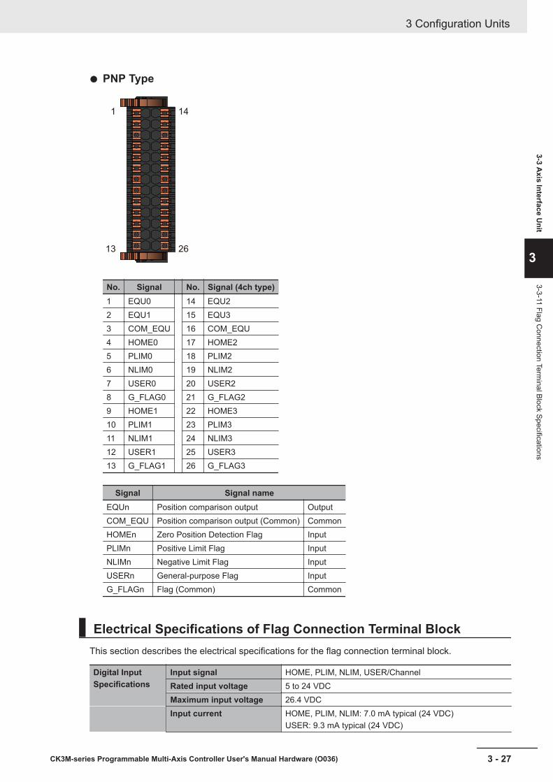
PNP Type
1
13
14
26
No. Signal No. Signal (4ch type)1 EQU0 14 EQU22 EQU1 15 EQU33 COM_EQU 16 COM_EQU4 HOME0 17 HOME25 PLIM0 18 PLIM26 NLIM0 19 NLIM27 USER0 20 USER28 G_FLAG0 21 G_FLAG29 HOME1 22 HOME310 PLIM1 23 PLIM311 NLIM1 24 NLIM312 USER1 25 USER313 G_FLAG1 26 G_FLAG3
Signal Signal nameEQUn Position comparison output OutputCOM_EQU Position comparison output (Common) CommonHOMEn Zero Position Detection Flag InputPLIMn Positive Limit Flag InputNLIMn Negative Limit Flag InputUSERn General-purpose Flag InputG_FLAGn Flag (Common) Common
Electrical Specifications of Flag Connection Terminal BlockThis section describes the electrical specifications for the flag connection terminal block.
Digital InputSpecifications
Input signal HOME, PLIM, NLIM, USER/ChannelRated input voltage 5 to 24 VDCMaximum input voltage 26.4 VDCInput current HOME, PLIM, NLIM: 7.0 mA typical (24 VDC)
USER: 9.3 mA typical (24 VDC)
3 Configuration Units
3 - 27CK3M-series Programmable Multi-Axis Controller User's Manual Hardware (O036)
3-3 Axis Interface U
nit
3
3-3-11 Flag Connection Term
inal Block Specifications
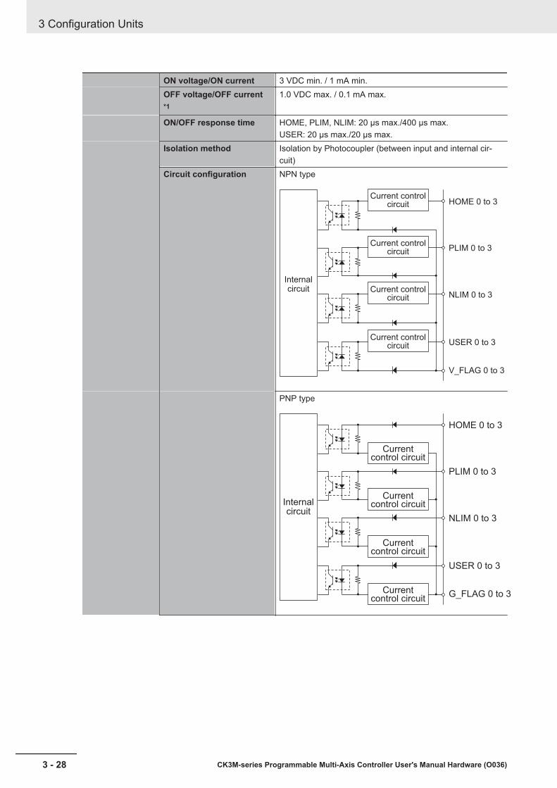
ON voltage/ON current 3 VDC min. / 1 mA min.OFF voltage/OFF current*1
1.0 VDC max. / 0.1 mA max.
ON/OFF response time HOME, PLIM, NLIM: 20 μs max./400 μs max.USER: 20 μs max./20 μs max.
Isolation method Isolation by Photocoupler (between input and internal cir-cuit)
Circuit configuration NPN type
HOME 0 to 3
PLIM 0 to 3
NLIM 0 to 3
USER 0 to 3
V_FLAG 0 to 3
Current control
circuit
Current control
circuit
Current control
circuit
Current control
circuit
Internal
circuit
PNP type
HOME 0 to 3
PLIM 0 to 3
NLIM 0 to 3
USER 0 to 3
G_FLAG 0 to 3
Current control circuit
Current control circuit
Current control circuit
Current control circuit
Internal
circuit
3 Configuration Units
3 - 28 CK3M-series Programmable Multi-Axis Controller User's Manual Hardware (O036)
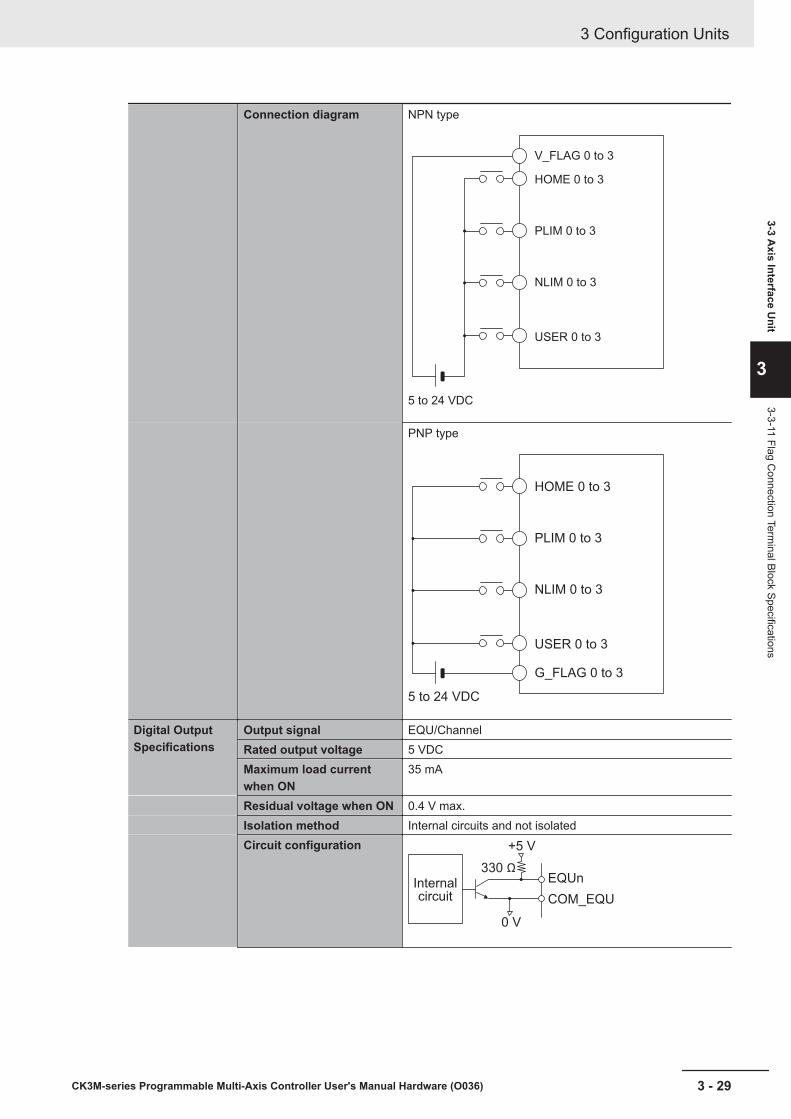
Connection diagram NPN type
V_FLAG 0 to 3
HOME 0 to 3
PLIM 0 to 3
NLIM 0 to 3
USER 0 to 3
5 to 24 VDC
PNP type
HOME 0 to 3
PLIM 0 to 3
NLIM 0 to 3
USER 0 to 3
G_FLAG 0 to 3
5 to 24 VDC
Digital OutputSpecifications
Output signal EQU/ChannelRated output voltage 5 VDCMaximum load currentwhen ON
35 mA
Residual voltage when ON 0.4 V max.Isolation method Internal circuits and not isolatedCircuit configuration
Internal
circuit
330 ΩEQUn
COM_EQU
0 V
+5 V
3 Configuration Units
3 - 29CK3M-series Programmable Multi-Axis Controller User's Manual Hardware (O036)
3-3 Axis Interface U
nit
3
3-3-11 Flag Connection Term
inal Block Specifications
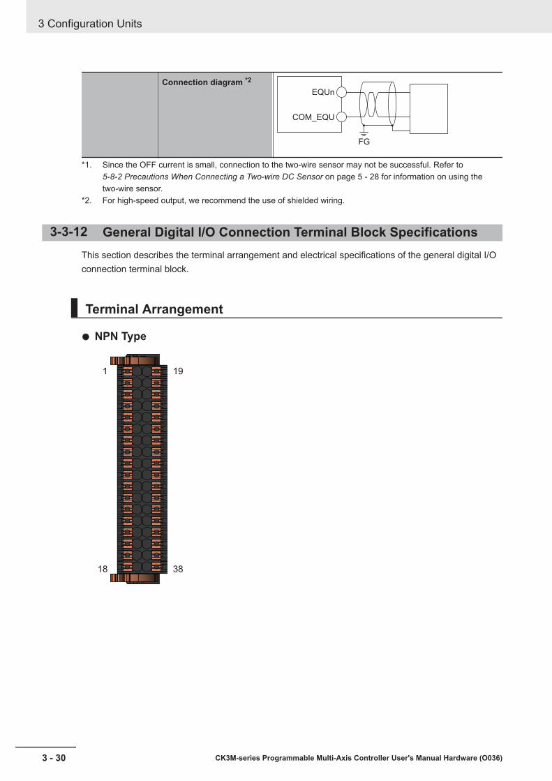
Connection diagram *2
FG
EQUn
COM_EQU
*1. Since the OFF current is small, connection to the two-wire sensor may not be successful. Refer to 5-8-2 Precautions When Connecting a Two-wire DC Sensor on page 5 - 28 for information on using thetwo-wire sensor.
*2. For high-speed output, we recommend the use of shielded wiring.
3-3-12 General Digital I/O Connection Terminal Block SpecificationsThis section describes the terminal arrangement and electrical specifications of the general digital I/Oconnection terminal block.
Terminal Arrangement
NPN Type
1
18
19
38
3 Configuration Units
3 - 30 CK3M-series Programmable Multi-Axis Controller User's Manual Hardware (O036)
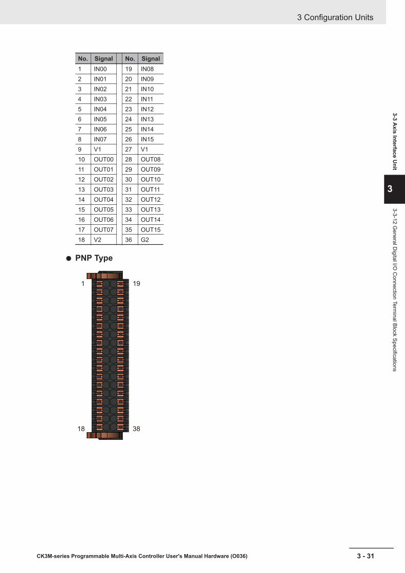
No. Signal No. Signal1 IN00 19 IN082 IN01 20 IN093 IN02 21 IN104 IN03 22 IN115 IN04 23 IN126 IN05 24 IN137 IN06 25 IN148 IN07 26 IN159 V1 27 V110 OUT00 28 OUT0811 OUT01 29 OUT0912 OUT02 30 OUT1013 OUT03 31 OUT1114 OUT04 32 OUT1215 OUT05 33 OUT1316 OUT06 34 OUT1417 OUT07 35 OUT1518 V2 36 G2
PNP Type
1
18
19
38
3 Configuration Units
3 - 31CK3M-series Programmable Multi-Axis Controller User's Manual Hardware (O036)
3-3 Axis Interface U
nit
3
3-3-12 General D
igital I/O C
onnection Terminal Block Specifications
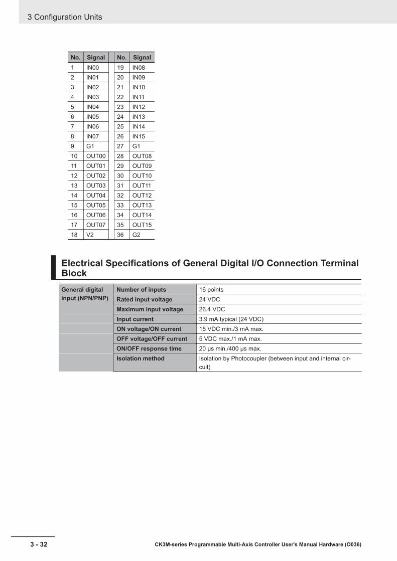
No. Signal No. Signal1 IN00 19 IN082 IN01 20 IN093 IN02 21 IN104 IN03 22 IN115 IN04 23 IN126 IN05 24 IN137 IN06 25 IN148 IN07 26 IN159 G1 27 G110 OUT00 28 OUT0811 OUT01 29 OUT0912 OUT02 30 OUT1013 OUT03 31 OUT1114 OUT04 32 OUT1215 OUT05 33 OUT1316 OUT06 34 OUT1417 OUT07 35 OUT1518 V2 36 G2
Electrical Specifications of General Digital I/O Connection TerminalBlockGeneral digitalinput (NPN/PNP)
Number of inputs 16 pointsRated input voltage 24 VDCMaximum input voltage 26.4 VDCInput current 3.9 mA typical (24 VDC)ON voltage/ON current 15 VDC min./3 mA max.OFF voltage/OFF current 5 VDC max./1 mA max.ON/OFF response time 20 μs min./400 μs max.Isolation method Isolation by Photocoupler (between input and internal cir-
cuit)
3 Configuration Units
3 - 32 CK3M-series Programmable Multi-Axis Controller User's Manual Hardware (O036)
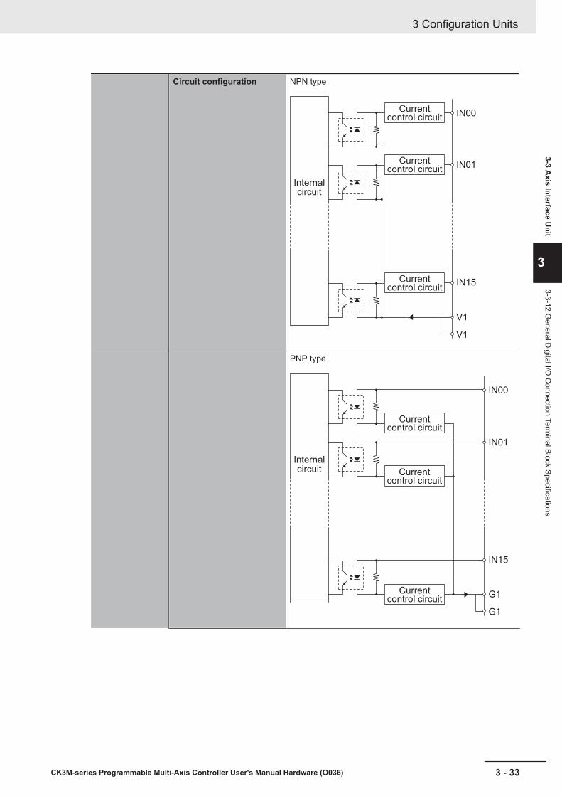
Circuit configuration NPN type
IN00
IN01
IN15
V1
V1
Current control circuit
Current control circuit
Current control circuit
Internal
circuit
PNP type
IN00
IN15
G1
G1
Current control circuit
Current control circuit
Current control circuit
Internal
circuit
IN01
3 Configuration Units
3 - 33CK3M-series Programmable Multi-Axis Controller User's Manual Hardware (O036)
3-3 Axis Interface U
nit
3
3-3-12 General D
igital I/O C
onnection Terminal Block Specifications
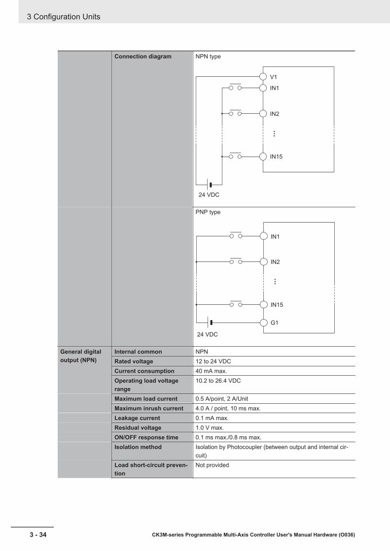
Connection diagram NPN type
V1
IN1
IN2
IN15
24 VDC
PNP type
24 VDC
IN1
IN2
IN15
G1
General digitaloutput (NPN)
Internal common NPNRated voltage 12 to 24 VDCCurrent consumption 40 mA max.Operating load voltagerange
10.2 to 26.4 VDC
Maximum load current 0.5 A/point, 2 A/UnitMaximum inrush current 4.0 A / point, 10 ms max.Leakage current 0.1 mA max.Residual voltage 1.0 V max.ON/OFF response time 0.1 ms max./0.8 ms max.Isolation method Isolation by Photocoupler (between output and internal cir-
cuit)Load short-circuit preven-tion
Not provided
3 Configuration Units
3 - 34 CK3M-series Programmable Multi-Axis Controller User's Manual Hardware (O036)

Circuit configuration
Internal
circuit
V2
G2
OUT00
OUT01
OUT15
Connection diagram NPN type
12 to 24 VDC
V2
OUT1
OUT2
OUT15
G2
L
L
L
General digitaloutput (PNP)
Internal common PNPRated voltage 12 to 24 VDCCurrent consumption 80 mA max.Operating load voltagerange
10.2 to 26.4 VDC
Maximum load current 0.5 A/point, 2 A/UnitMaximum inrush current 4.0 A / point, 10 ms max.Leakage current 0.1 mA max.Current voltage 1.0 V max.ON/OFF response time 0.1 ms max./0.8 ms max.Isolation method Isolation by Photocoupler (between output and internal cir-
cuit)Load short-circuit preven-tion
Provided
3 Configuration Units
3 - 35CK3M-series Programmable Multi-Axis Controller User's Manual Hardware (O036)
3-3 Axis Interface U
nit
3
3-3-12 General D
igital I/O C
onnection Terminal Block Specifications
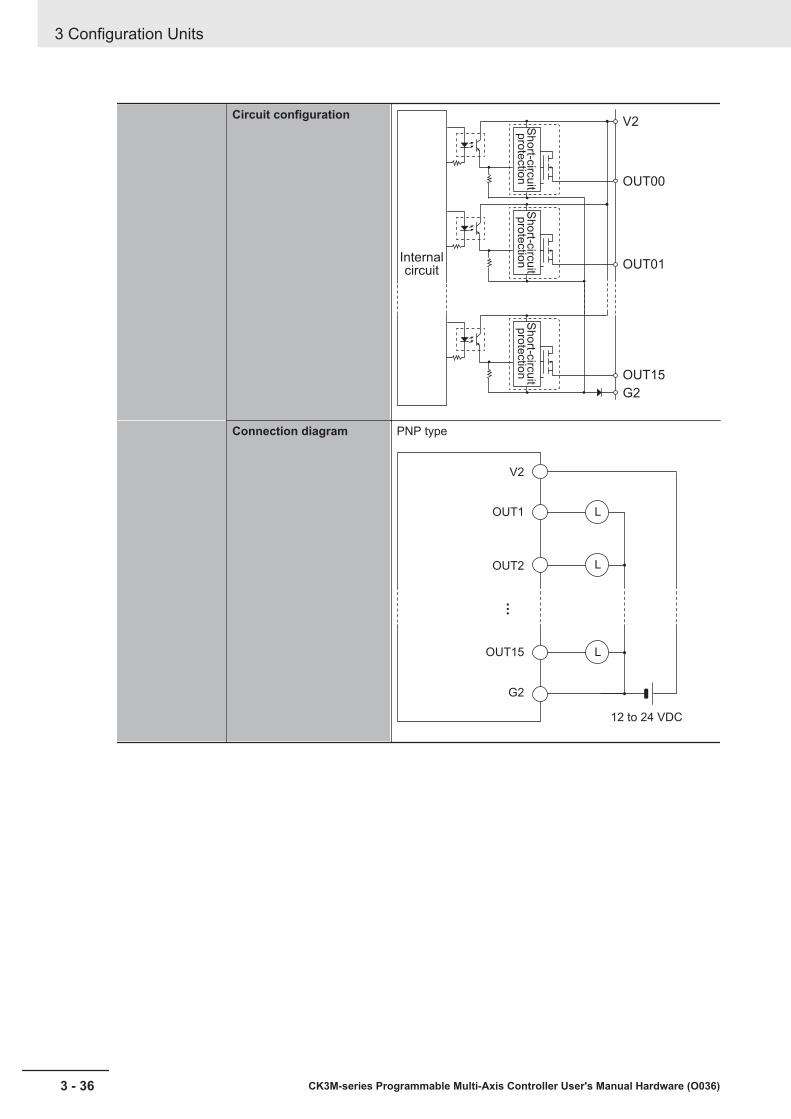
Circuit configuration
Internal circuit
V2
G2
OUT00
OUT01
OUT15
Sh
ort-c
ircu
it p
rote
ctio
nS
ho
rt-circ
uit
pro
tectio
nS
ho
rt-circ
uit
pro
tectio
n
Connection diagram PNP type
12 to 24 VDC
V2
OUT1
OUT2
OUT15
G2
L
L
L
3 Configuration Units
3 - 36 CK3M-series Programmable Multi-Axis Controller User's Manual Hardware (O036)
4Installation
This section describes how to install the CK3M-series Programmable Multi-Axis Con-troller as well as details on installation locations.
4-1 Processing at Power ON and Power OFF .................................................. 4 - 24-1-1 Power ON Operation .................................................................................... 4 - 24-1-2 Power OFF Operation................................................................................... 4 - 2
4-2 Fail-safe Circuits .......................................................................................... 4 - 34-3 Mounting Units ............................................................................................. 4 - 4
4-3-1 Installation in a Control Panel ....................................................................... 4 - 44-3-2 Connecting Adjacent Units ........................................................................... 4 - 84-3-3 Mounting to DIN Track .................................................................................. 4 - 94-3-4 DIN Track and Accessories ........................................................................ 4 - 104-3-5 Assembled Appearance and Dimensions....................................................4 - 11
4-4 Control Panel Installation.......................................................................... 4 - 154-4-1 Temperature................................................................................................ 4 - 154-4-2 Humidity...................................................................................................... 4 - 164-4-3 Vibration and Shock.................................................................................... 4 - 174-4-4 Atmosphere ................................................................................................ 4 - 174-4-5 Electrical Environment ................................................................................ 4 - 174-4-6 Grounding ................................................................................................... 4 - 22
4 - 1CK3M-series Programmable Multi-Axis Controller User's Manual Hardware (O036)
4
4-1 Processing at Power ON and PowerOFF
4-1-1 Power ON OperationOnce the power supply to the Power Supply Unit starts, the CPU Unit enters the program operationready status after the following time elapses.In addition, when the unit is in the operation-ready status, the RDY LED lights up.
CPU Unit Startup Time at Power ONIt takes approximately 40 to 60 seconds for the CPU Unit to start up.Since the startup time is affected by the slave/unit configuration, confirm it on an actual device.
4-1-2 Power OFF OperationIf the power is interrupted while a user program writes data in the USB memory or the built-in flashmemory, the data may be destroyed.Confirm that no write processes are underway before you turn off the power.
If data is destroyed, issue a re-initialization command ($$$***) from IDE, and perform a re-download ofthe program.If the IDE connection cannot be performed, refer to 6-3-3 Initialization of CPU Unit Using USB Memoryon page 6 - 8 and implement initialization.
4 Installation
4 - 2 CK3M-series Programmable Multi-Axis Controller User's Manual Hardware (O036)
4-2 Fail-safe Circuits
WARNINGProvide safety measures in external circuits to ensure safety in the sys-tem if an abnormality occurs due to malfunction of the system due toother external factors affecting operation. Not doing so may result in se-rious accidents due to incorrect operation.• Emergency stop circuits, interlock circuits, limit circuits, and similar
safety measures must be provided in external control circuits.• You must take fail-safe measures to ensure safety in the event of in-
correct, missing, or abnormal signals caused by broken signal lines,momentary power interruptions, or other causes.
• The use of an Uninterruptible Power Supply (UPS) allows normal op-eration to continue even if a momentary power interruption occurs,possibly resulting in the reception of an erroneous signal from an ex-ternal device affected by the momentary power failure. Take externalfail-safe measures. Where necessary, monitor the power supply volt-age on the system for external devices and use it as an interlock con-dition
• Unintended behavior may occur if an error occurs in the internalmemory of the product. As a countermeasure for these problems, ex-ternal safety measures must be provided to ensure safe operation ofthe system.
• The Controller will turn OFF all outputs from Output Units in the fol-lowing cases. The slaves will operate according to the settings in theslaves.a) If a power supply error occursb) If the power supply connection becomes faultyc) If a CPU error (watchdog timer error) or CPU reset occursd) If a major fault level Controller error occurse) While the CPU Unit is on standby until RUN mode is entered after
the power is turned ONf) If a system initialization error occurs
As a countermeasure for these problems, external safety measuresmust be provided to ensure safe operation of the system.• The outputs may remain ON or OFF due to welding or burning of the
output relays or destruction of the output transistors. As a counter-measure for these problems, external safety measures must be pro-vided to ensure safe operation of the system.
4 Installation
4 - 3CK3M-series Programmable Multi-Axis Controller User's Manual Hardware (O036)
4-2 Fail-safe Circuits
4
4-3 Mounting UnitsThis section describes how to mount Units to the CK3M-series Controller.
Precautions for Safe Use
Always turn OFF the power supply to the Controller before attempting any of the following.• Mounting or removing CK3W-AX Units or Motion Controllers• Assembling the Units• Setting rotary switches• Connecting cables or wiring the system• Connecting or disconnecting the terminal blocks or connectorsThe built-in power supply of the Controller may continue to supply power after the power supplyis turned OFF. The POWER indicator remains lit as long as power is supplied. Make sure thatthe POWER indicator is not lit before you perform any of the above operations.
Precautions for Correct Use
• Follow the instructions in this manual to correctly perform installation.• Do not operate or store the Units in the following locations. Doing so may result in burning, in
operation stopping, or in malfunction.a) Locations subject to direct sunlightb) Locations subject to temperatures or humidity outside the range specified in the specifica-
tionsc) Locations subject to condensation as the result of severe changes in temperatured) Locations subject to corrosive or flammable gasese) Locations subject to dust (especially iron dust) or saltsf) Locations subject to exposure to water, oil, or chemicalsg) Locations subject to shock or vibration
• Take appropriate and sufficient countermeasures during installation in the following locations.a) Locations near devices that produce strong, high-frequency noiseb) Locations subject to static electricity or other forms of noisec) Locations subject to strong electromagnetic fieldsd) Locations subject to possible exposure to radioactivitye) Locations close to power lines
4-3-1 Installation in a Control Panel
Installation in Cabinets or Control PanelsWhen the CK3M-series Controller is being installed in a cabinet or control panel, be sure to provideproper ambient conditions as well as access for operation and maintenance.
Temperature ControlThe ambient temperature within the CK3M-series Controller must be within the operating range of0 to 55°C. When necessary, take the following steps to maintain the proper temperature.• Provide enough space for good air flow.• Do not install the Controller above equipment that generates a large amount of heat such as
heaters, transformers, or high-capacity resistors.• If the ambient temperature exceeds 55°C, install a cooling fan or air conditioner.
4 Installation
4 - 4 CK3M-series Programmable Multi-Axis Controller User's Manual Hardware (O036)

Louver
Control panel
CK3M
-series
Controller
Fan
Accessibility for Operation and Maintenance• To ensure safe access for operation and maintenance, separate the Controller as much as possi-
ble from high-voltage equipment and power machinery.• It will be easy to operate the Controller if it is mounted at a height of 1.0 to 1.6 m above the floor.
Improving Noise Resistance• Do not mount the Controller in a control panel containing high-voltage equipment.• Install the Controller at least 200 mm away from power lines.
CK3M-series
Controller
Power lines
200 mm
min.
200 mm min.
• Ground the mounting plate between the Controller and the mounting surface.
Controller Orientation• Each Rack must be mounted in the following position to provide proper cooling. This position is
called an upright position.
• Do not install a Rack in any of the following positions.
4 Installation
4 - 5CK3M-series Programmable Multi-Axis Controller User's Manual Hardware (O036)
4-3 Mounting U
nits
4
4-3-1 Installation in a Control Panel

DIN Track
DIN Track
Mounting with the DIN Track on the Bottom
Mounting with the Rack Upside Down
Mounting with the DIN Track Installed
Vertically
Mounting with the DIN Track on the Top
Additional Information
A Controller must be mounted on a DIN Track. It cannot be mounted with screws.
Wiring DuctsWhenever possible, route I/O wiring through wiring ducts.Install mounting bracket so that it is easy to fish wire through the duct. It is handy to have the ductat the same height as the CPU Rack.
Duct
Duct
Unit
20 mm min.
20 mm min.
DIN Track
4 Installation
4 - 6 CK3M-series Programmable Multi-Axis Controller User's Manual Hardware (O036)
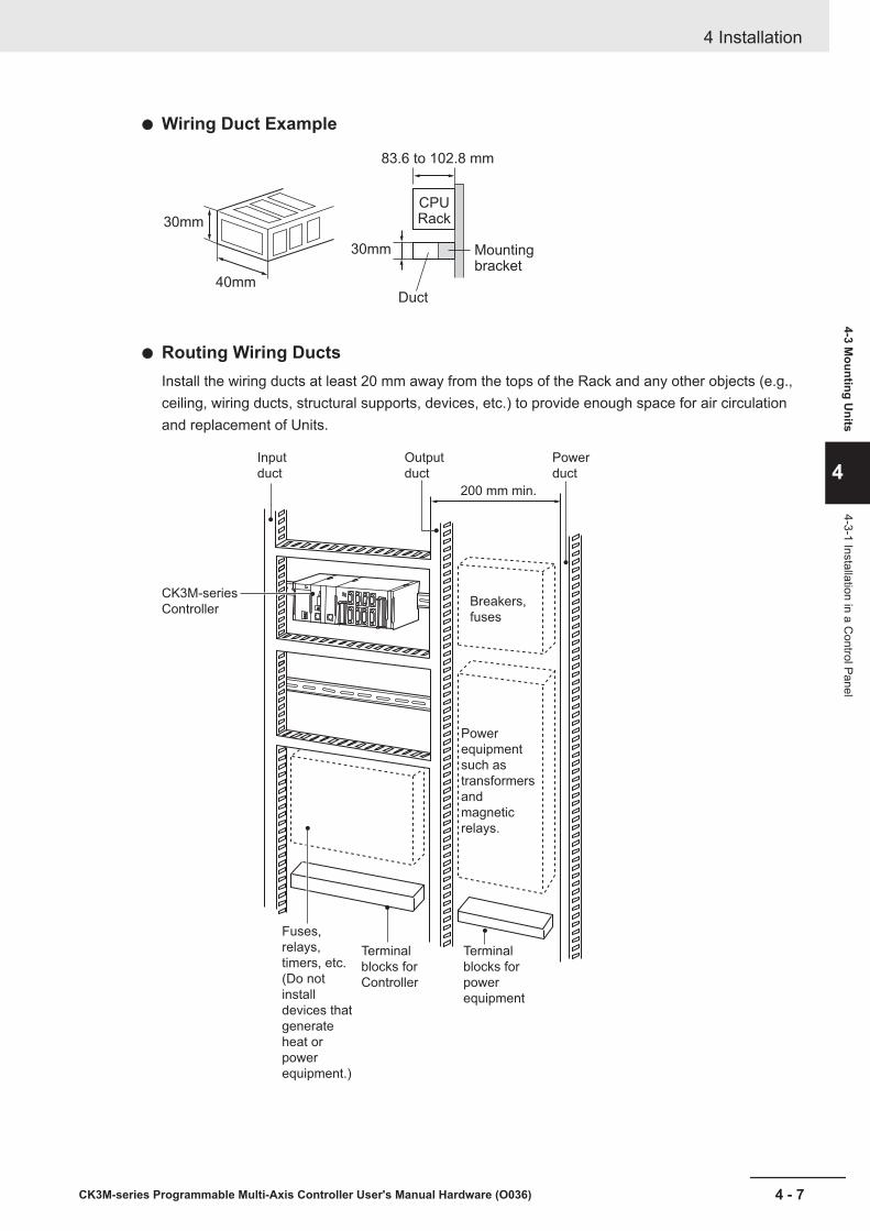
Wiring Duct Example
CPU Rack
83.6 to 102.8 mm
Duct
30mm
30mm
40mm
Mounting bracket
Routing Wiring DuctsInstall the wiring ducts at least 20 mm away from the tops of the Rack and any other objects (e.g.,ceiling, wiring ducts, structural supports, devices, etc.) to provide enough space for air circulationand replacement of Units.
Input
duct
Power
duct
Output
duct
Breakers,
fuses
CK3M-series
Controller
200 mm min.
Power
equipment
such as
transformers
and
magnetic
relays.
Terminal
blocks for
power
equipment
Terminal
blocks for
Controller
Fuses,
relays,
timers, etc.
(Do not
install
devices that
generate
heat or
power
equipment.)
4 Installation
4 - 7CK3M-series Programmable Multi-Axis Controller User's Manual Hardware (O036)
4-3 Mounting U
nits
4
4-3-1 Installation in a Control Panel

4-3-2 Connecting Adjacent UnitsThe Units that make up a CK3M-series Controller can be connected simply by pressing the Units to-gether and locking the sliders by moving them toward the back of the Units. The End Cover is con-nected in the same way to the Unit on the far right side of the Controller.
1 Join the Units so that the connectors fit exactly.
Hook Hook holesConnector
2 The yellow sliders at the top and bottom of each Unit lock the Units together. Move the sliderstoward the back of the Units as shown below until they click into place.
Move the sliders toward the back
until they lock into place.
Release
Slider
Lock
Precautions for Safe Use
The sliders on the top and bottom of the CK3W Unit must be completely locked (until they clickinto place) after connecting the adjacent Unit connectors.
3 Attach the End Cover to the Unit on the far right side of the Rack.
Power Supply Unit
CPU Rack
CPU Unit Configuration Units(2 max.)
End cover(included with CPU Unit)
4 Installation
4 - 8 CK3M-series Programmable Multi-Axis Controller User's Manual Hardware (O036)
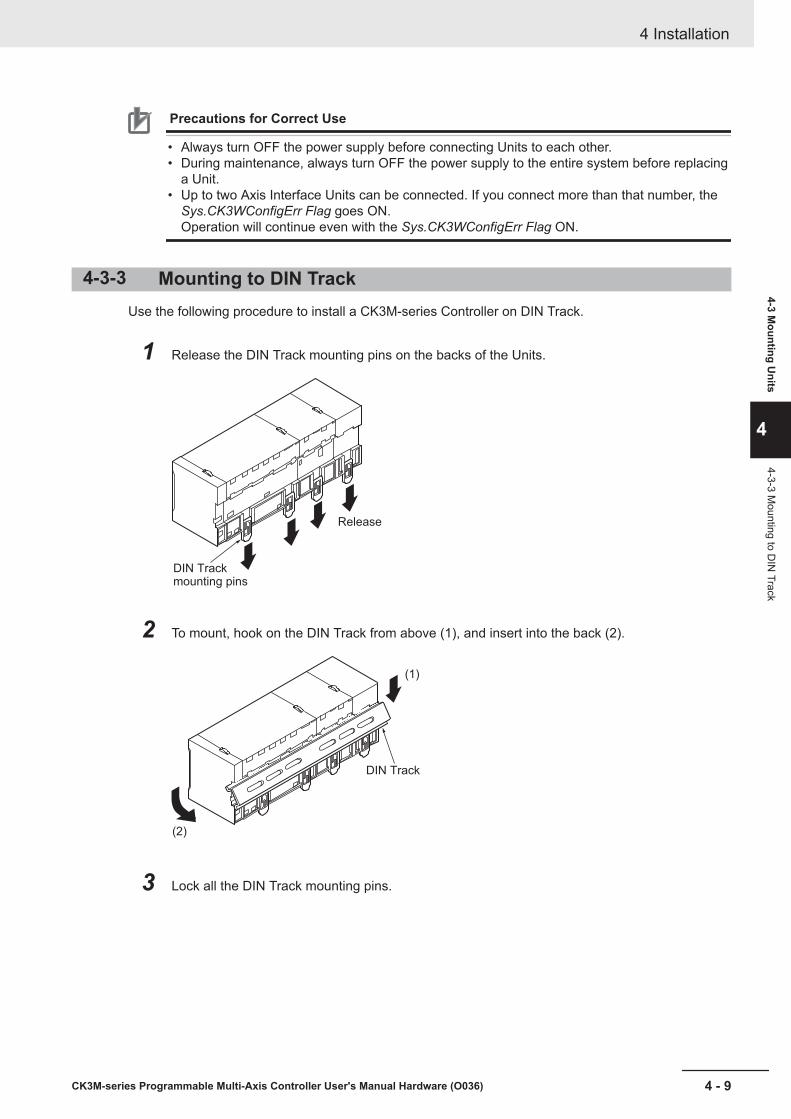
Precautions for Correct Use
• Always turn OFF the power supply before connecting Units to each other.• During maintenance, always turn OFF the power supply to the entire system before replacing
a Unit.• Up to two Axis Interface Units can be connected. If you connect more than that number, the
Sys.CK3WConfigErr Flag goes ON.Operation will continue even with the Sys.CK3WConfigErr Flag ON.
4-3-3 Mounting to DIN TrackUse the following procedure to install a CK3M-series Controller on DIN Track.
1 Release the DIN Track mounting pins on the backs of the Units.
Release
DIN Track mounting pins
2 To mount, hook on the DIN Track from above (1), and insert into the back (2).
DIN Track
(1)
(2)
3 Lock all the DIN Track mounting pins.
4 Installation
4 - 9CK3M-series Programmable Multi-Axis Controller User's Manual Hardware (O036)
4-3 Mounting U
nits
4
4-3-3 Mounting to D
IN Track
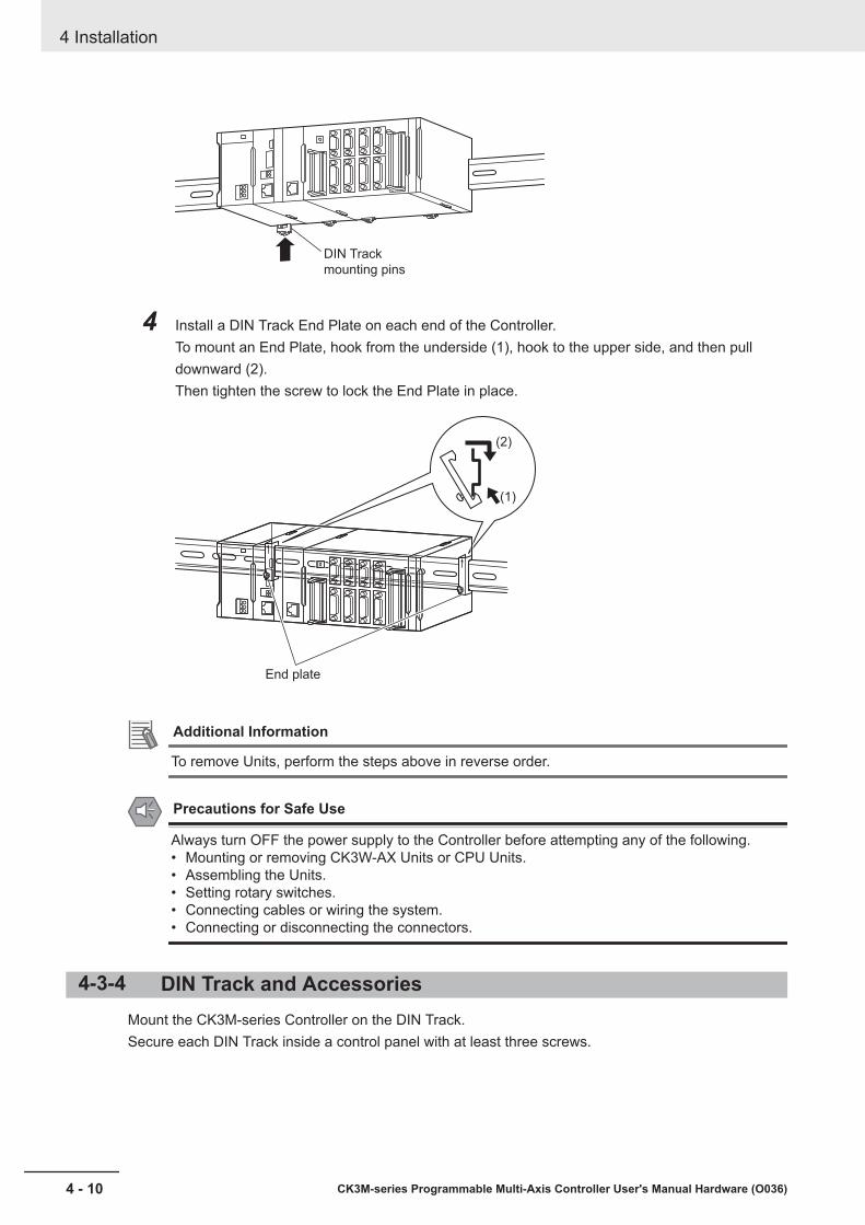
DIN Track
mounting pins
4 Install a DIN Track End Plate on each end of the Controller.To mount an End Plate, hook from the underside (1), hook to the upper side, and then pulldownward (2).Then tighten the screw to lock the End Plate in place.
End plate
(1)
(2)
Additional Information
To remove Units, perform the steps above in reverse order.
Precautions for Safe Use
Always turn OFF the power supply to the Controller before attempting any of the following.• Mounting or removing CK3W-AX Units or CPU Units.• Assembling the Units.• Setting rotary switches.• Connecting cables or wiring the system.• Connecting or disconnecting the connectors.
4-3-4 DIN Track and AccessoriesMount the CK3M-series Controller on the DIN Track.Secure each DIN Track inside a control panel with at least three screws.
4 Installation
4 - 10 CK3M-series Programmable Multi-Axis Controller User's Manual Hardware (O036)
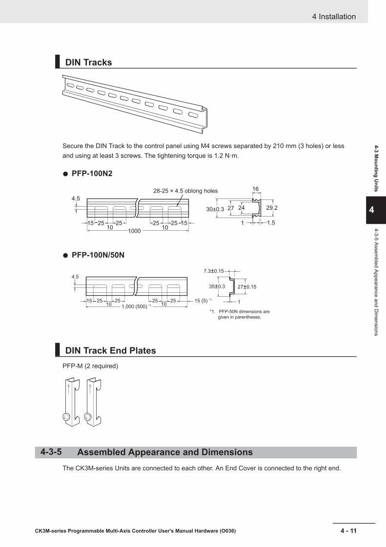
DIN Tracks
Secure the DIN Track to the control panel using M4 screws separated by 210 mm (3 holes) or lessand using at least 3 screws. The tightening torque is 1.2 N·m.
PFP-100N2
28-25 × 4.5 oblong holes
4.5
15 152510 10
25 25 25
1000
30±0.3 27 29.224
16
1 1.5
PFP-100N/50N
1,000 (500) *1
1510
4.5
25 25 2510
25 15 (5) *11
7.3±0.15
35±0.3 27±0.15
*1. PFP-50N dimensions are
given in parentheses.
DIN Track End PlatesPFP-M (2 required)
4-3-5 Assembled Appearance and DimensionsThe CK3M-series Units are connected to each other. An End Cover is connected to the right end.
4 Installation
4 - 11CK3M-series Programmable Multi-Axis Controller User's Manual Hardware (O036)
4-3 Mounting U
nits
4
4-3-5 Assembled Appearance and D
imensions

Dimensions
Power Supply Unit
Model Unit width (mm)CK3W-PD048 45
CPU Unit
Model Unit width (mm)CK3M-CPU101 63.2CK3M-CPU111CK3M-CPU121
End Cover
Model Unit width (mm)CK3W-TER11 15.6
Axis Interface Unit
Model Unit width (mm)CK3W-AX1414N 130CK3W-AX1515NCK3W-AX1414PCK3W-AX1515P
Design Example for Width W
Power Supply Unit CPU Unit Configuration Units
(Unit mm)W
Name Model Unit width(mm) Qty Subtotal unit
width (mm)Power Supply Unit CK3W-PD048 45 1 45
4 Installation
4 - 12 CK3M-series Programmable Multi-Axis Controller User's Manual Hardware (O036)
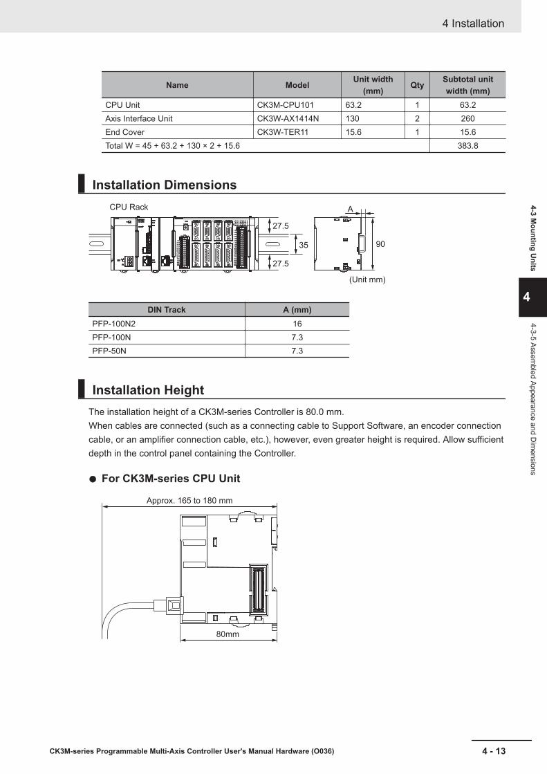
Name Model Unit width(mm) Qty Subtotal unit
width (mm)CPU Unit CK3M-CPU101 63.2 1 63.2Axis Interface Unit CK3W-AX1414N 130 2 260End Cover CK3W-TER11 15.6 1 15.6Total W = 45 + 63.2 + 130 × 2 + 15.6 383.8
Installation Dimensions
27.5
35 90
A
27.5
CPU Rack
(Unit mm)
DIN Track A (mm)PFP-100N2 16PFP-100N 7.3PFP-50N 7.3
Installation HeightThe installation height of a CK3M-series Controller is 80.0 mm.When cables are connected (such as a connecting cable to Support Software, an encoder connectioncable, or an amplifier connection cable, etc.), however, even greater height is required. Allow sufficientdepth in the control panel containing the Controller.
For CK3M-series CPU Unit
Approx. 165 to 180 mm
80mm
4 Installation
4 - 13CK3M-series Programmable Multi-Axis Controller User's Manual Hardware (O036)
4-3 Mounting U
nits
4
4-3-5 Assembled Appearance and D
imensions
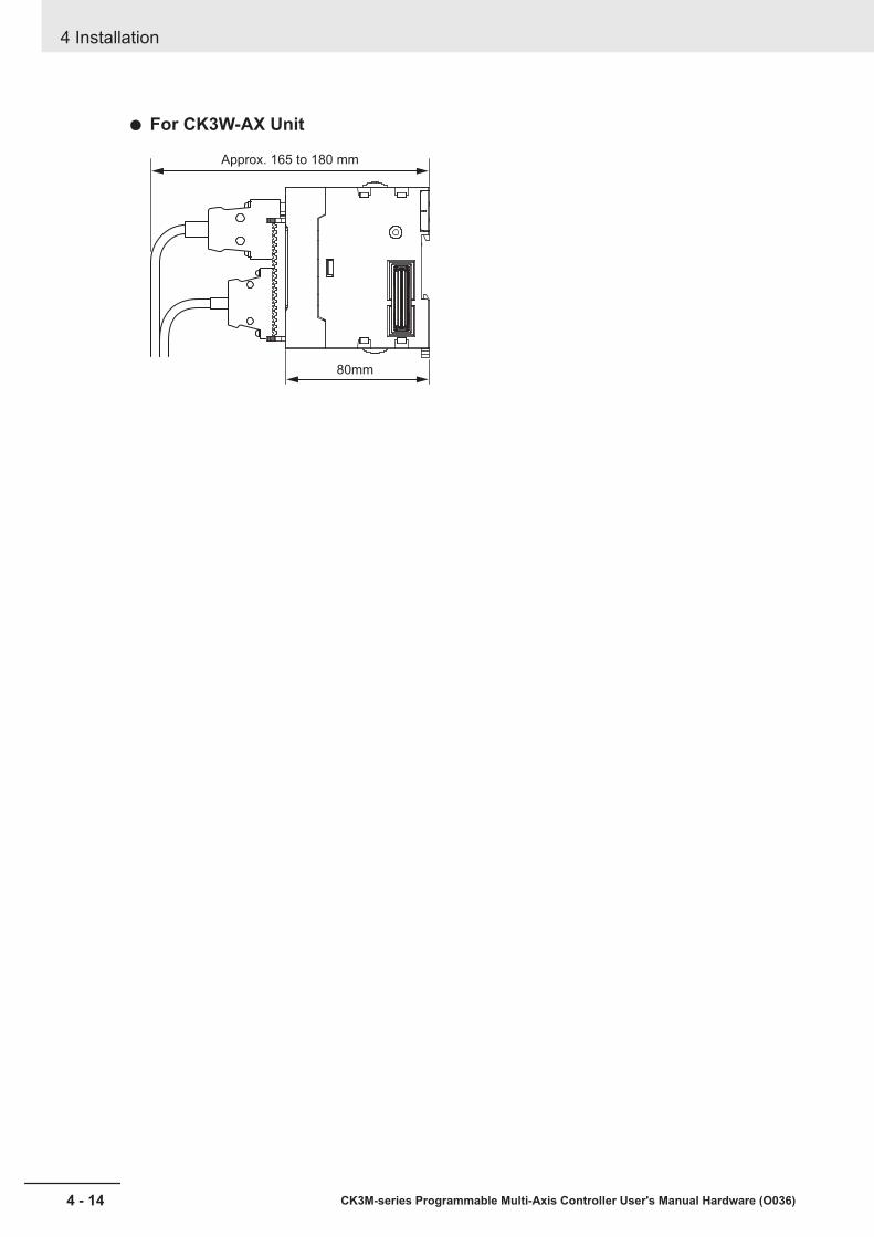
For CK3W-AX Unit
Approx. 165 to 180 mm
80mm
4 Installation
4 - 14 CK3M-series Programmable Multi-Axis Controller User's Manual Hardware (O036)
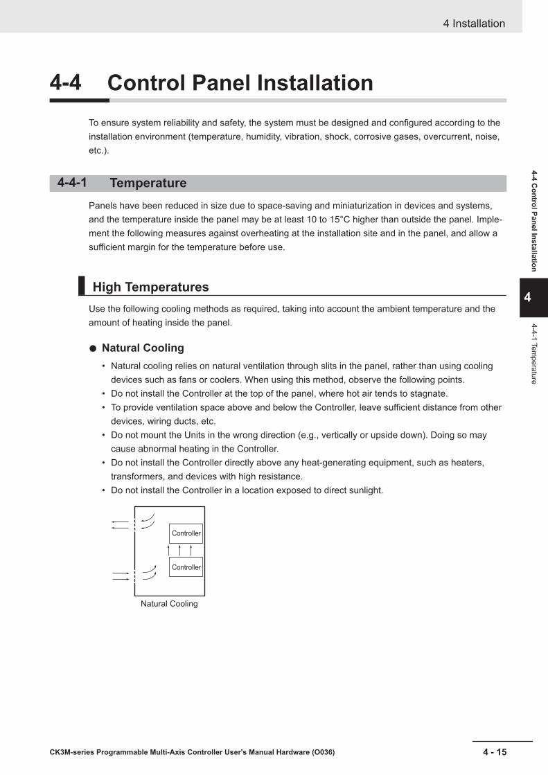
4-4 Control Panel InstallationTo ensure system reliability and safety, the system must be designed and configured according to theinstallation environment (temperature, humidity, vibration, shock, corrosive gases, overcurrent, noise,etc.).
4-4-1 TemperaturePanels have been reduced in size due to space-saving and miniaturization in devices and systems,and the temperature inside the panel may be at least 10 to 15°C higher than outside the panel. Imple-ment the following measures against overheating at the installation site and in the panel, and allow asufficient margin for the temperature before use.
High TemperaturesUse the following cooling methods as required, taking into account the ambient temperature and theamount of heating inside the panel.
Natural Cooling• Natural cooling relies on natural ventilation through slits in the panel, rather than using cooling
devices such as fans or coolers. When using this method, observe the following points.• Do not install the Controller at the top of the panel, where hot air tends to stagnate.• To provide ventilation space above and below the Controller, leave sufficient distance from other
devices, wiring ducts, etc.• Do not mount the Units in the wrong direction (e.g., vertically or upside down). Doing so may
cause abnormal heating in the Controller.• Do not install the Controller directly above any heat-generating equipment, such as heaters,
transformers, and devices with high resistance.• Do not install the Controller in a location exposed to direct sunlight.
Natural Cooling
Controller
Controller
4 Installation
4 - 15CK3M-series Programmable Multi-Axis Controller User's Manual Hardware (O036)
4-4 Control Panel Installation
4
4-4-1 Temperature
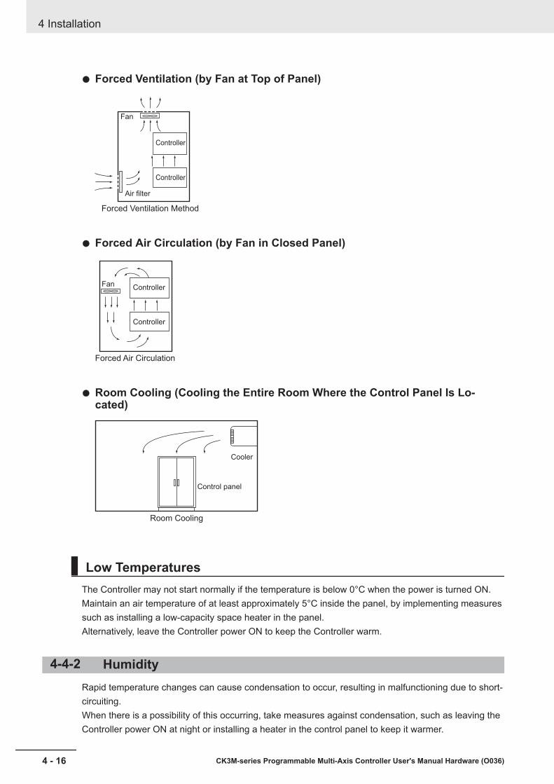
Forced Ventilation (by Fan at Top of Panel)
Air filter
Fan
Forced Ventilation Method
Controller
Controller
Forced Air Circulation (by Fan in Closed Panel)
Fan
Forced Air Circulation
Controller
Controller
Room Cooling (Cooling the Entire Room Where the Control Panel Is Lo-cated)
Room Cooling
Cooler
Control panel
Low TemperaturesThe Controller may not start normally if the temperature is below 0°C when the power is turned ON.Maintain an air temperature of at least approximately 5°C inside the panel, by implementing measuressuch as installing a low-capacity space heater in the panel.Alternatively, leave the Controller power ON to keep the Controller warm.
4-4-2 HumidityRapid temperature changes can cause condensation to occur, resulting in malfunctioning due to short-circuiting.When there is a possibility of this occurring, take measures against condensation, such as leaving theController power ON at night or installing a heater in the control panel to keep it warmer.
4 Installation
4 - 16 CK3M-series Programmable Multi-Axis Controller User's Manual Hardware (O036)
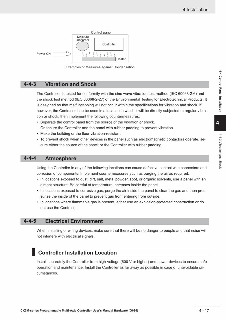
Moistureabsorber
Power ON
Control panel
Heater
Examples of Measures against Condensation
Controller
4-4-3 Vibration and ShockThe Controller is tested for conformity with the sine wave vibration test method (IEC 60068-2-6) andthe shock test method (IEC 60068-2-27) of the Environmental Testing for Electrotechnical Products. Itis designed so that malfunctioning will not occur within the specifications for vibration and shock. If,however, the Controller is to be used in a location in which it will be directly subjected to regular vibra-tion or shock, then implement the following countermeasures:• Separate the control panel from the source of the vibration or shock.
Or secure the Controller and the panel with rubber padding to prevent vibration.• Make the building or the floor vibration-resistant.• To prevent shock when other devices in the panel such as electromagnetic contactors operate, se-
cure either the source of the shock or the Controller with rubber padding.
4-4-4 AtmosphereUsing the Controller in any of the following locations can cause defective contact with connectors andcorrosion of components. Implement countermeasures such as purging the air as required.• In locations exposed to dust, dirt, salt, metal powder, soot, or organic solvents, use a panel with an
airtight structure. Be careful of temperature increases inside the panel.• In locations exposed to corrosive gas, purge the air inside the panel to clear the gas and then pres-
surize the inside of the panel to prevent gas from entering from outside.• In locations where flammable gas is present, either use an explosion-protected construction or do
not use the Controller.
4-4-5 Electrical EnvironmentWhen installing or wiring devices, make sure that there will be no danger to people and that noise willnot interfere with electrical signals.
Controller Installation LocationInstall separately the Controller from high-voltage (600 V or higher) and power devices to ensure safeoperation and maintenance. Install the Controller as far away as possible in case of unavoidable cir-cumstances.
4 Installation
4 - 17CK3M-series Programmable Multi-Axis Controller User's Manual Hardware (O036)
4-4 Control Panel Installation
4
4-4-3 Vibration and Shock
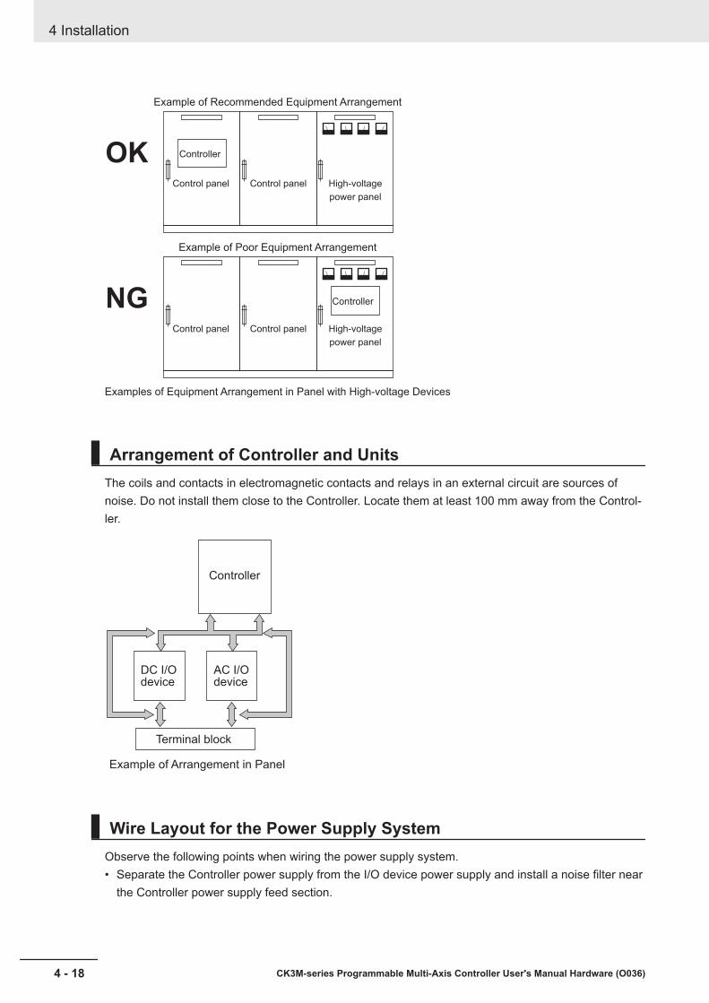
Example of Recommended Equipment Arrangement
Control panel Control panel High-voltage
power panel
Examples of Equipment Arrangement in Panel with High-voltage Devices
Example of Poor Equipment Arrangement
Control panel Control panel High-voltage
power panel
Controller
Controller
OK
NG
Arrangement of Controller and UnitsThe coils and contacts in electromagnetic contacts and relays in an external circuit are sources ofnoise. Do not install them close to the Controller. Locate them at least 100 mm away from the Control-ler.
Controller
DC I/Odevice
AC I/Odevice
Terminal block
Example of Arrangement in Panel
Wire Layout for the Power Supply SystemObserve the following points when wiring the power supply system.• Separate the Controller power supply from the I/O device power supply and install a noise filter near
the Controller power supply feed section.
4 Installation
4 - 18 CK3M-series Programmable Multi-Axis Controller User's Manual Hardware (O036)
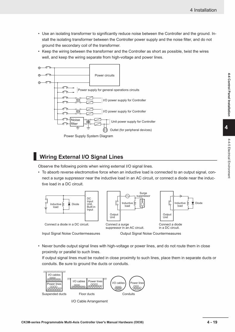
• Use an isolating transformer to significantly reduce noise between the Controller and the ground. In-stall the isolating transformer between the Controller power supply and the noise filter, and do notground the secondary coil of the transformer.
• Keep the wiring between the transformer and the Controller as short as possible, twist the wireswell, and keep the wiring separate from high-voltage and power lines.
Unit power supply for Controller
I/O power supply for Controller
Power Supply System Diagram
Power circuits
Power supply for general operations circuits
Outlet (for peripheral devices)
I/O power supply for Controller
Noise
filter
Wiring External I/O Signal LinesObserve the following points when wiring external I/O signal lines.• To absorb reverse electromotive force when an inductive load is connected to an output signal, con-
nect a surge suppressor near the inductive load in an AC circuit, or connect a diode near the induc-tive load in a DC circuit.
Input Signal Noise Countermeasures
DC Input Unit, Built-in Input
Inductiveload
Diode
Connect a diode in a DC circuit.
Output Signal Noise Countermeasures
OutputUnit
OutputUnit
Connect a diodein a DC circuit.
Connect a surgesuppressor in an AC circuit.
Inductiveload
DiodeInductiveload
Surgesuppressor
• Never bundle output signal lines with high-voltage or power lines, and do not route them in closeproximity or parallel to such lines.If output signal lines must be routed in close proximity to such lines, place them in separate ducts orconduits. Be sure to ground the ducts or conduits.
I/O Cable Arrangement
Floor ducts ConduitsSuspended ducts
I/O cables
I/O cablesPower lines
Power linesI/O cables Power lines
4 Installation
4 - 19CK3M-series Programmable Multi-Axis Controller User's Manual Hardware (O036)
4-4 Control Panel Installation
4
4-4-5 Electrical Environment
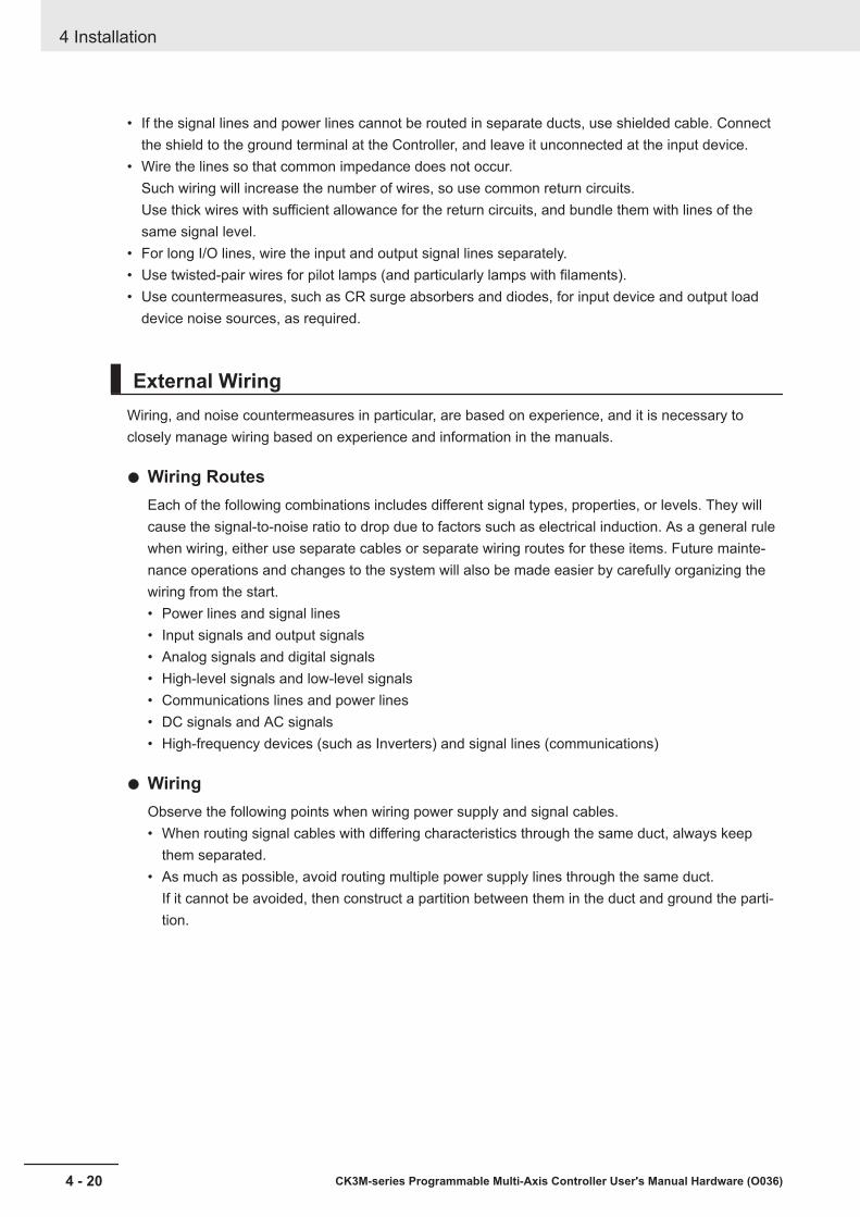
• If the signal lines and power lines cannot be routed in separate ducts, use shielded cable. Connectthe shield to the ground terminal at the Controller, and leave it unconnected at the input device.
• Wire the lines so that common impedance does not occur.Such wiring will increase the number of wires, so use common return circuits.Use thick wires with sufficient allowance for the return circuits, and bundle them with lines of thesame signal level.
• For long I/O lines, wire the input and output signal lines separately.• Use twisted-pair wires for pilot lamps (and particularly lamps with filaments).• Use countermeasures, such as CR surge absorbers and diodes, for input device and output load
device noise sources, as required.
External WiringWiring, and noise countermeasures in particular, are based on experience, and it is necessary toclosely manage wiring based on experience and information in the manuals.
Wiring RoutesEach of the following combinations includes different signal types, properties, or levels. They willcause the signal-to-noise ratio to drop due to factors such as electrical induction. As a general rulewhen wiring, either use separate cables or separate wiring routes for these items. Future mainte-nance operations and changes to the system will also be made easier by carefully organizing thewiring from the start.• Power lines and signal lines• Input signals and output signals• Analog signals and digital signals• High-level signals and low-level signals• Communications lines and power lines• DC signals and AC signals• High-frequency devices (such as Inverters) and signal lines (communications)
WiringObserve the following points when wiring power supply and signal cables.• When routing signal cables with differing characteristics through the same duct, always keep
them separated.• As much as possible, avoid routing multiple power supply lines through the same duct.
If it cannot be avoided, then construct a partition between them in the duct and ground the parti-tion.
4 Installation
4 - 20 CK3M-series Programmable Multi-Axis Controller User's Manual Hardware (O036)
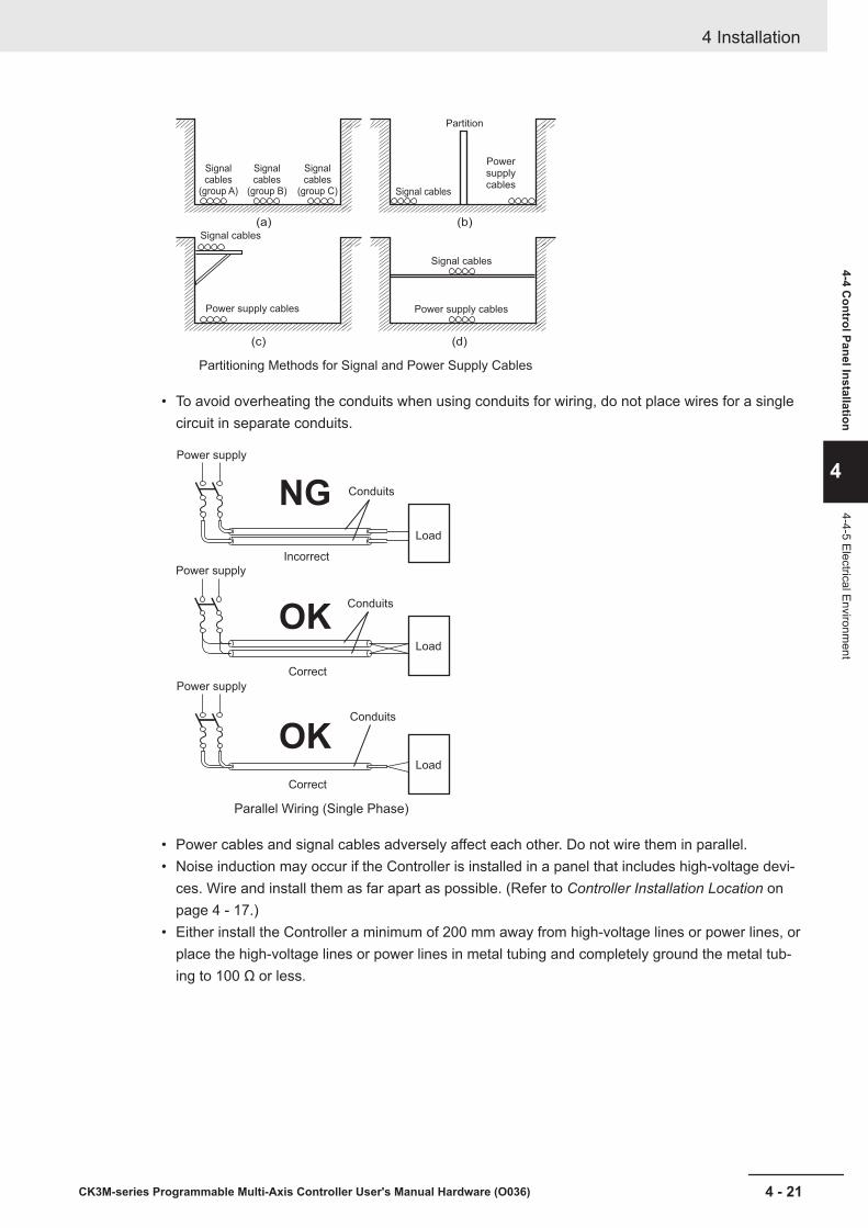
Partitioning Methods for Signal and Power Supply Cables
(a) (b)
(c) (d)
Signal cables
Signal cables
Signal cables
Power supply cables
Powersupplycables
Power supply cables
Partition
Signalcables
(group A)
Signalcables
(group B)
Signalcables
(group C)
• To avoid overheating the conduits when using conduits for wiring, do not place wires for a singlecircuit in separate conduits.
Parallel Wiring (Single Phase)
Correct
Correct
Power supply
Incorrect
Power supply
Power supply
Load
Load
Load
Conduits
Conduits
Conduits
OK
OK
NG
• Power cables and signal cables adversely affect each other. Do not wire them in parallel.• Noise induction may occur if the Controller is installed in a panel that includes high-voltage devi-
ces. Wire and install them as far apart as possible. (Refer to Controller Installation Location onpage 4 - 17.)
• Either install the Controller a minimum of 200 mm away from high-voltage lines or power lines, orplace the high-voltage lines or power lines in metal tubing and completely ground the metal tub-ing to 100 Ω or less.
4 Installation
4 - 21CK3M-series Programmable Multi-Axis Controller User's Manual Hardware (O036)
4-4 Control Panel Installation
4
4-4-5 Electrical Environment
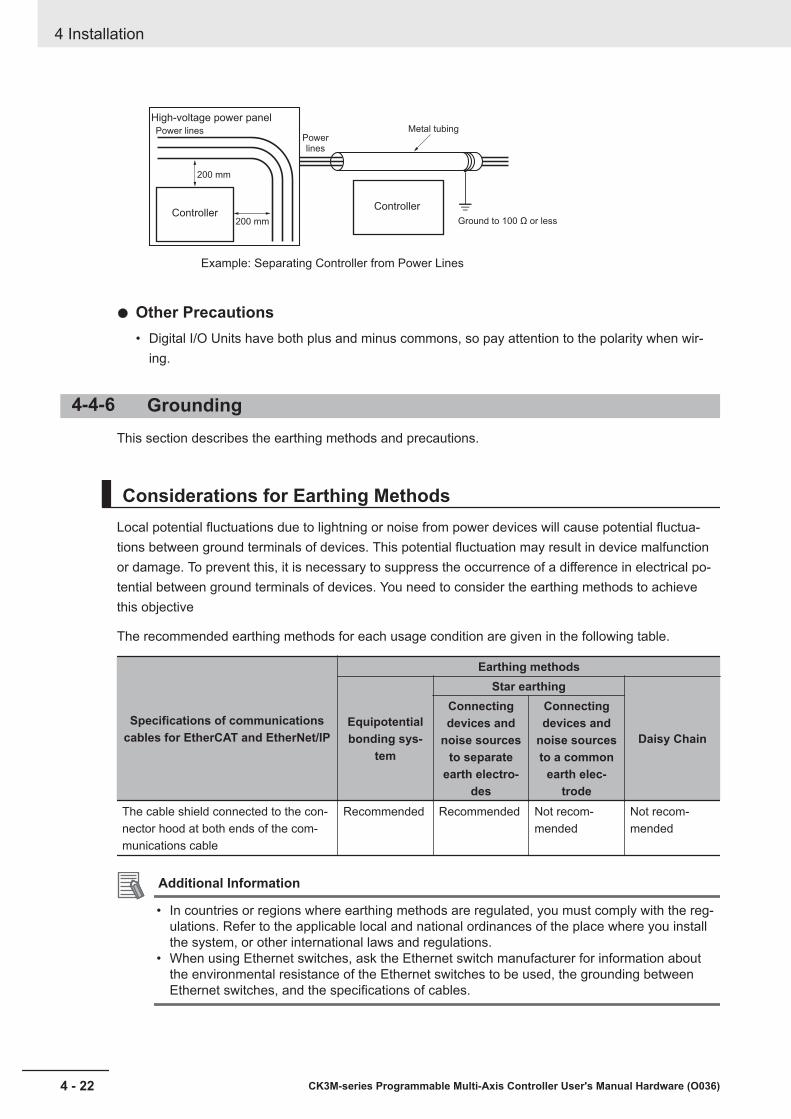
Example: Separating Controller from Power Lines
Metal tubing
200 mm
200 mm
High-voltage power panel
Power linesPowerlines
Ground to 100 Ω or lessController
Controller
Other Precautions• Digital I/O Units have both plus and minus commons, so pay attention to the polarity when wir-
ing.
4-4-6 GroundingThis section describes the earthing methods and precautions.
Considerations for Earthing MethodsLocal potential fluctuations due to lightning or noise from power devices will cause potential fluctua-tions between ground terminals of devices. This potential fluctuation may result in device malfunctionor damage. To prevent this, it is necessary to suppress the occurrence of a difference in electrical po-tential between ground terminals of devices. You need to consider the earthing methods to achievethis objective
The recommended earthing methods for each usage condition are given in the following table.
Specifications of communicationscables for EtherCAT and EtherNet/IP
Earthing methods
Equipotentialbonding sys-
tem
Star earthing
Daisy Chain
Connectingdevices and
noise sourcesto separate
earth electro-des
Connectingdevices and
noise sourcesto a common
earth elec-trode
The cable shield connected to the con-nector hood at both ends of the com-munications cable
Recommended Recommended Not recom-mended
Not recom-mended
Additional Information
• In countries or regions where earthing methods are regulated, you must comply with the reg-ulations. Refer to the applicable local and national ordinances of the place where you installthe system, or other international laws and regulations.
• When using Ethernet switches, ask the Ethernet switch manufacturer for information aboutthe environmental resistance of the Ethernet switches to be used, the grounding betweenEthernet switches, and the specifications of cables.
4 Installation
4 - 22 CK3M-series Programmable Multi-Axis Controller User's Manual Hardware (O036)
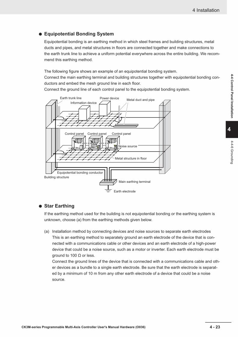
Equipotential Bonding SystemEquipotential bonding is an earthing method in which steel frames and building structures, metalducts and pipes, and metal structures in floors are connected together and make connections tothe earth trunk line to achieve a uniform potential everywhere across the entire building. We recom-mend this earthing method.
The following figure shows an example of an equipotential bonding system.Connect the main earthing terminal and building structures together with equipotential bonding con-ductors and embed the mesh ground line in each floor.Connect the ground line of each control panel to the equipotential bonding system.
Information device
Power deviceMetal duct and pipe
Building structure
Equipotential bonding conductor
Main earthing terminal
Earth electrode
Metal structure in floor
Earth trunk line
Control panel
Hub
Control panel Control panel
Noise source
Star EarthingIf the earthing method used for the building is not equipotential bonding or the earthing system isunknown, choose (a) from the earthing methods given below.
(a) Installation method by connecting devices and noise sources to separate earth electrodesThis is an earthing method to separately ground an earth electrode of the device that is con-nected with a communications cable or other devices and an earth electrode of a high-powerdevice that could be a noise source, such as a motor or inverter. Each earth electrode must beground to 100 Ω or less.Connect the ground lines of the device that is connected with a communications cable and oth-er devices as a bundle to a single earth electrode. Be sure that the earth electrode is separat-ed by a minimum of 10 m from any other earth electrode of a device that could be a noisesource.
4 Installation
4 - 23CK3M-series Programmable Multi-Axis Controller User's Manual Hardware (O036)
4-4 Control Panel Installation
4
4-4-6 Grounding

Hub
A device that couldbe a noise source
CK3M-series Programmable Multi-Axis ControllerNX-series CPU Unit
Control panel Other device
10 m min.
(b) Installation by connecting devices and noise sources to a common earth electrodeThis is an earthing method to connect the device that is connected with a communications ca-ble, other devices, and a device that could be a noise source, to a common earth electrode.This earthing method is not recommended, because the device that is a potential noise sourcemay interfere electromagnetically with other devices.
Hub
CK3M-series Programmable Multi-Axis ControllerNX-series CPU Unit
A device that couldbe a noise source
Control panel Other device
Daisy ChainThis is an earthing method to connect the device that is connected with a communications cable,other devices, and a device that could be a noise source using a daisy-chain topology to a commonearth electrode.This earthing method is not recommended because the device that could be a noise source mayinterfere electromagnetically with other devices.
4 Installation
4 - 24 CK3M-series Programmable Multi-Axis Controller User's Manual Hardware (O036)
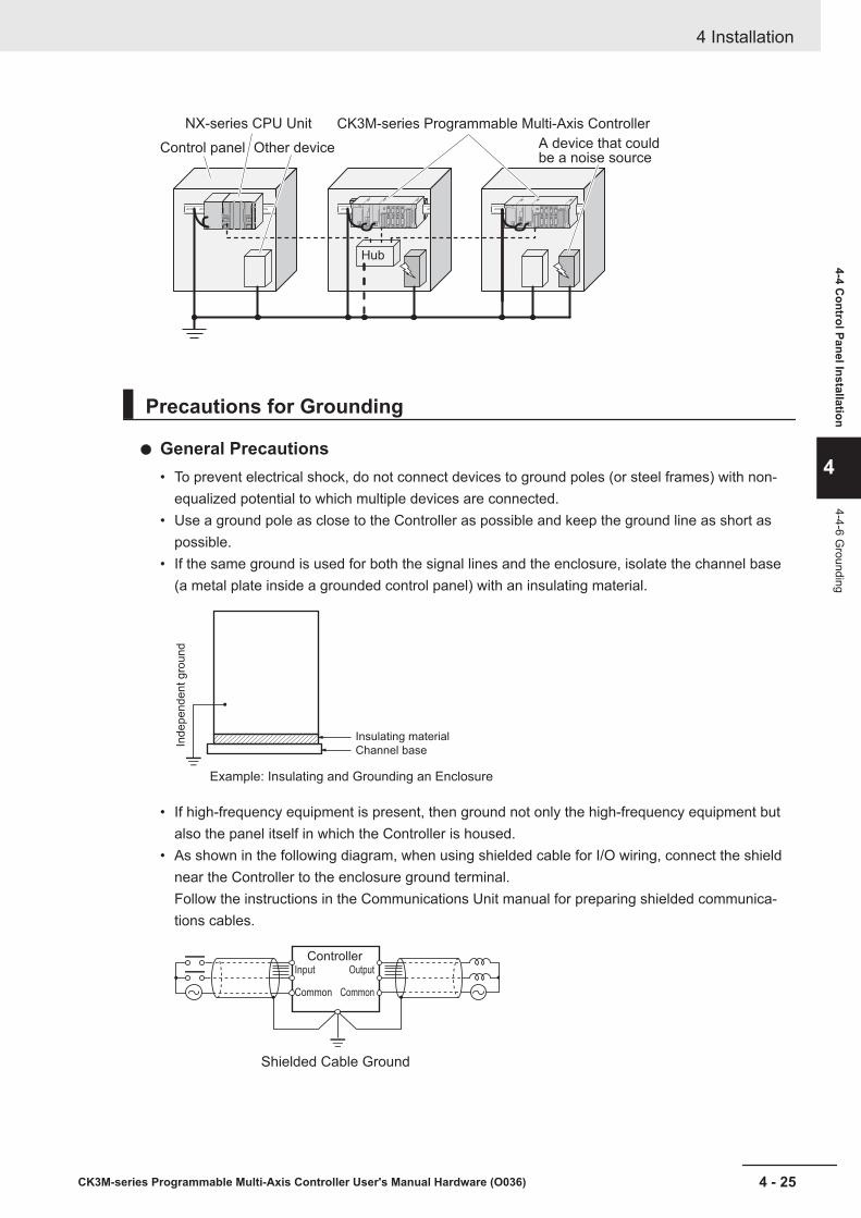
Hub
CK3M-series Programmable Multi-Axis ControllerNX-series CPU Unit
A device that couldbe a noise source
Control panel Other device
Precautions for Grounding
General Precautions• To prevent electrical shock, do not connect devices to ground poles (or steel frames) with non-
equalized potential to which multiple devices are connected.• Use a ground pole as close to the Controller as possible and keep the ground line as short as
possible.• If the same ground is used for both the signal lines and the enclosure, isolate the channel base
(a metal plate inside a grounded control panel) with an insulating material.
Example: Insulating and Grounding an Enclosure
Ind
ep
en
de
nt g
rou
nd
Insulating material
Channel base
• If high-frequency equipment is present, then ground not only the high-frequency equipment butalso the panel itself in which the Controller is housed.
• As shown in the following diagram, when using shielded cable for I/O wiring, connect the shieldnear the Controller to the enclosure ground terminal.Follow the instructions in the Communications Unit manual for preparing shielded communica-tions cables.
Shielded Cable Ground
ControllerOutput
Common
Input
Common
4 Installation
4 - 25CK3M-series Programmable Multi-Axis Controller User's Manual Hardware (O036)
4-4 Control Panel Installation
4
4-4-6 Grounding
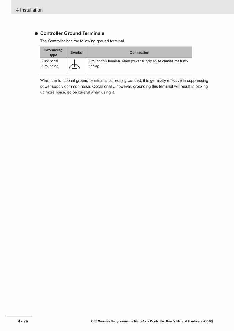
Controller Ground TerminalsThe Controller has the following ground terminal.
Groundingtype Symbol Connection
FunctionalGrounding
Ground this terminal when power supply noise causes malfunc-tioning.
When the functional ground terminal is correctly grounded, it is generally effective in suppressingpower supply common noise. Occasionally, however, grounding this terminal will result in pickingup more noise, so be careful when using it.
4 Installation
4 - 26 CK3M-series Programmable Multi-Axis Controller User's Manual Hardware (O036)
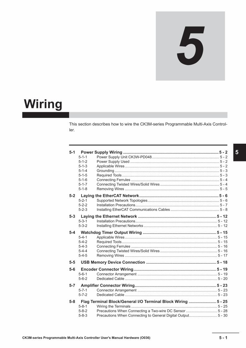
5Wiring
This section describes how to wire the CK3M-series Programmable Multi-Axis Control-ler.
5-1 Power Supply Wiring ................................................................................... 5 - 25-1-1 Power Supply Unit CK3W-PD048................................................................. 5 - 25-1-2 Power Supply Used ...................................................................................... 5 - 25-1-3 Applicable Wires ........................................................................................... 5 - 25-1-4 Grounding ..................................................................................................... 5 - 35-1-5 Required Tools.............................................................................................. 5 - 35-1-6 Connecting Ferrules ..................................................................................... 5 - 45-1-7 Connecting Twisted Wires/Solid Wires ......................................................... 5 - 45-1-8 Removing Wires ........................................................................................... 5 - 5
5-2 Laying the EtherCAT Network..................................................................... 5 - 65-2-1 Supported Network Topologies..................................................................... 5 - 65-2-2 Installation Precautions................................................................................. 5 - 75-2-3 Installing EtherCAT Communications Cables ............................................... 5 - 8
5-3 Laying the Ethernet Network .................................................................... 5 - 125-3-1 Installation Precautions............................................................................... 5 - 125-3-2 Installing Ethernet Networks ....................................................................... 5 - 12
5-4 Watchdog Timer Output Wiring ................................................................ 5 - 155-4-1 Applicable Wires ......................................................................................... 5 - 155-4-2 Required Tools............................................................................................ 5 - 155-4-3 Connecting Ferrules ................................................................................... 5 - 165-4-4 Connecting Twisted Wires/Solid Wires ....................................................... 5 - 165-4-5 Removing Wires ......................................................................................... 5 - 17
5-5 USB Memory Device Connection ............................................................. 5 - 185-6 Encoder Connector Wiring........................................................................ 5 - 19
5-6-1 Connector Arrangement ............................................................................. 5 - 195-6-2 Dedicated Cable ......................................................................................... 5 - 20
5-7 Amplifier Connector Wiring....................................................................... 5 - 235-7-1 Connector Arrangement ............................................................................. 5 - 235-7-2 Dedicated Cable ......................................................................................... 5 - 23
5-8 Flag Terminal Block/General I/O Terminal Block Wiring ........................ 5 - 255-8-1 Wiring the Terminals ................................................................................... 5 - 255-8-2 Precautions When Connecting a Two-wire DC Sensor .............................. 5 - 285-8-3 Precautions When Connecting to General Digital Output........................... 5 - 30
5 - 1CK3M-series Programmable Multi-Axis Controller User's Manual Hardware (O036)
5
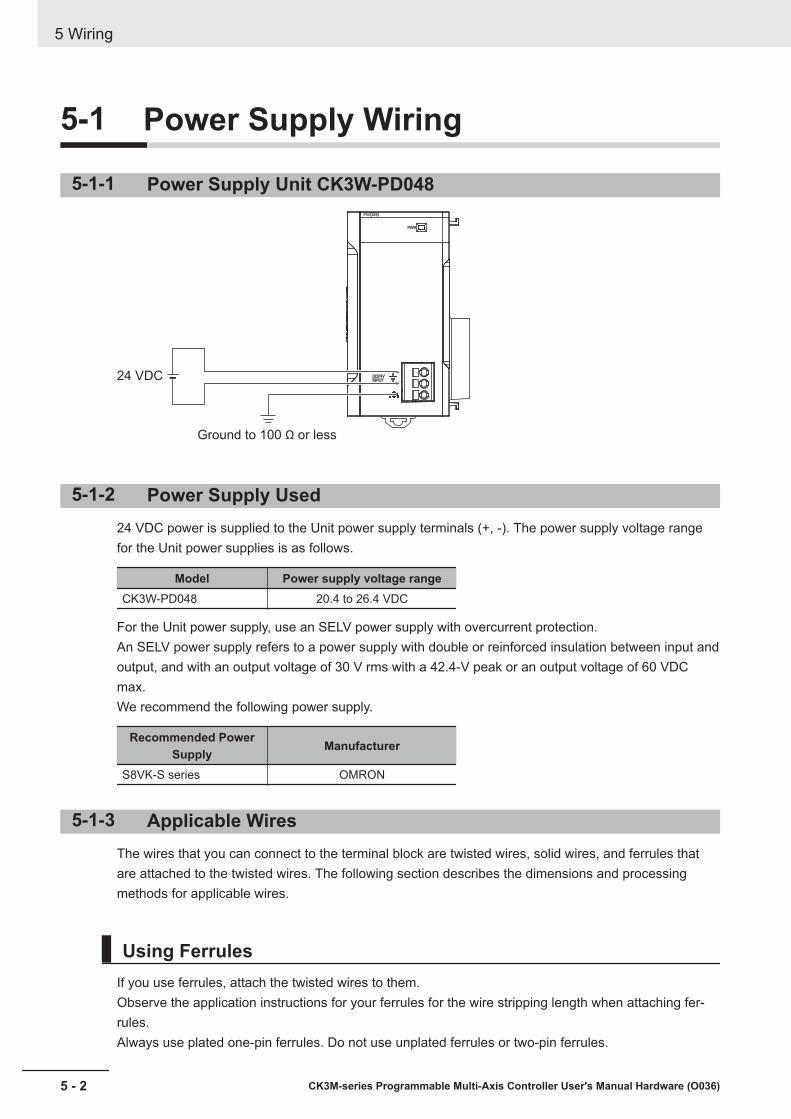
5-1 Power Supply Wiring
5-1-1 Power Supply Unit CK3W-PD048
24 VDC
Ground to 100 Ω or less
5-1-2 Power Supply Used24 VDC power is supplied to the Unit power supply terminals (+, -). The power supply voltage rangefor the Unit power supplies is as follows.
Model Power supply voltage rangeCK3W-PD048 20.4 to 26.4 VDC
For the Unit power supply, use an SELV power supply with overcurrent protection.An SELV power supply refers to a power supply with double or reinforced insulation between input andoutput, and with an output voltage of 30 V rms with a 42.4-V peak or an output voltage of 60 VDCmax.We recommend the following power supply.
Recommended PowerSupply Manufacturer
S8VK-S series OMRON
5-1-3 Applicable WiresThe wires that you can connect to the terminal block are twisted wires, solid wires, and ferrules thatare attached to the twisted wires. The following section describes the dimensions and processingmethods for applicable wires.
Using FerrulesIf you use ferrules, attach the twisted wires to them.Observe the application instructions for your ferrules for the wire stripping length when attaching fer-rules.Always use plated one-pin ferrules. Do not use unplated ferrules or two-pin ferrules.
5 Wiring
5 - 2 CK3M-series Programmable Multi-Axis Controller User's Manual Hardware (O036)
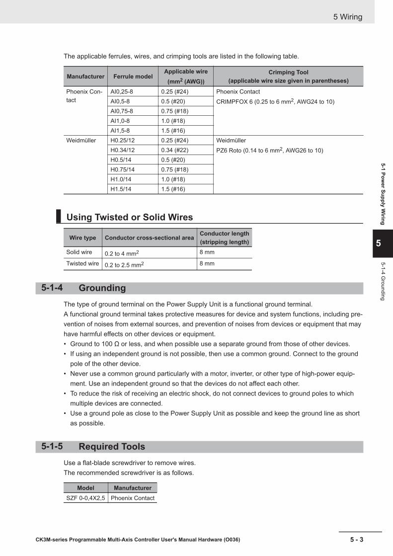
The applicable ferrules, wires, and crimping tools are listed in the following table.
Manufacturer Ferrule modelApplicable wire
(mm2 (AWG))Crimping Tool
(applicable wire size given in parentheses)
Phoenix Con-tact
AI0,25-8 0.25 (#24) Phoenix ContactCRIMPFOX 6 (0.25 to 6 mm2, AWG24 to 10)AI0,5-8 0.5 (#20)
AI0,75-8 0.75 (#18)AI1,0-8 1.0 (#18)AI1,5-8 1.5 (#16)
Weidmüller H0.25/12 0.25 (#24) WeidmüllerPZ6 Roto (0.14 to 6 mm2, AWG26 to 10)H0.34/12 0.34 (#22)
H0.5/14 0.5 (#20)H0.75/14 0.75 (#18)H1.0/14 1.0 (#18)H1.5/14 1.5 (#16)
Using Twisted or Solid Wires
Wire type Conductor cross-sectional area Conductor length(stripping length)
Solid wire 0.2 to 4 mm2 8 mm
Twisted wire 0.2 to 2.5 mm2 8 mm
5-1-4 GroundingThe type of ground terminal on the Power Supply Unit is a functional ground terminal.A functional ground terminal takes protective measures for device and system functions, including pre-vention of noises from external sources, and prevention of noises from devices or equipment that mayhave harmful effects on other devices or equipment.• Ground to 100 Ω or less, and when possible use a separate ground from those of other devices.• If using an independent ground is not possible, then use a common ground. Connect to the ground
pole of the other device.• Never use a common ground particularly with a motor, inverter, or other type of high-power equip-
ment. Use an independent ground so that the devices do not affect each other.• To reduce the risk of receiving an electric shock, do not connect devices to ground poles to which
multiple devices are connected.• Use a ground pole as close to the Power Supply Unit as possible and keep the ground line as short
as possible.
5-1-5 Required ToolsUse a flat-blade screwdriver to remove wires.The recommended screwdriver is as follows.
Model ManufacturerSZF 0-0,4X2,5 Phoenix Contact
5 Wiring
5 - 3CK3M-series Programmable Multi-Axis Controller User's Manual Hardware (O036)
5-1 Power Supply W
iring
5
5-1-4 Grounding
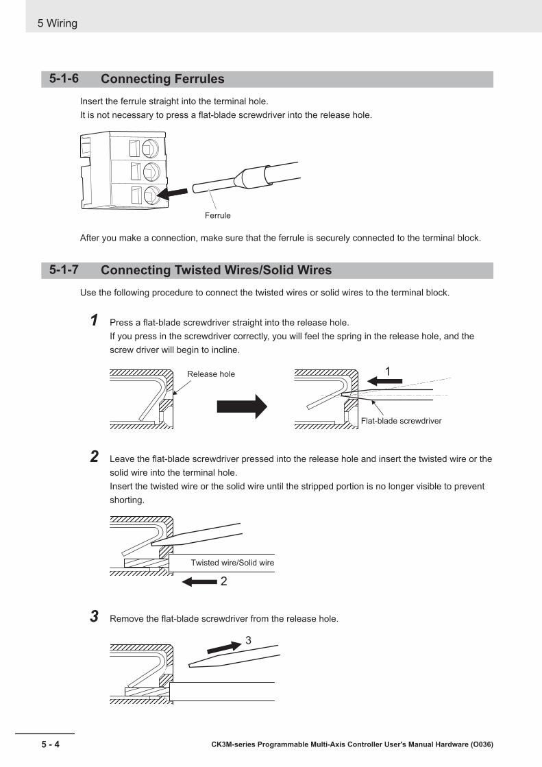
5-1-6 Connecting FerrulesInsert the ferrule straight into the terminal hole.It is not necessary to press a flat-blade screwdriver into the release hole.
Ferrule
After you make a connection, make sure that the ferrule is securely connected to the terminal block.
5-1-7 Connecting Twisted Wires/Solid WiresUse the following procedure to connect the twisted wires or solid wires to the terminal block.
1 Press a flat-blade screwdriver straight into the release hole.If you press in the screwdriver correctly, you will feel the spring in the release hole, and thescrew driver will begin to incline.
Release hole
Flat-blade screwdriver
1
2 Leave the flat-blade screwdriver pressed into the release hole and insert the twisted wire or thesolid wire into the terminal hole.Insert the twisted wire or the solid wire until the stripped portion is no longer visible to preventshorting.
2
Twisted wire/Solid wire
3 Remove the flat-blade screwdriver from the release hole.
3
5 Wiring
5 - 4 CK3M-series Programmable Multi-Axis Controller User's Manual Hardware (O036)

After you make a connection, make sure that the twisted wire or the solid wire is securely connected tothe terminal block.
Precautions for Safe Use
• Make sure that all wiring is correct.• Do not bend the cable forcibly. Doing so may break the cable.
5-1-8 Removing WiresUse the following procedure to remove the wires from the terminal block.The removal method is the same for ferrules, twisted wires, and solid wires.
1 Press a flat-blade screwdriver straight into the release hole.If you press in the screwdriver correctly, you will feel the spring in the release hole, and thescrew driver will begin to incline.
1
Wire
Flat-blade screwdriver
2 Leave the flat-blade screwdriver pressed into the release hole and pull out the wire.
2
3 Remove the flat-blade screwdriver from the release hole.
3
Precautions for Safe Use
• Make sure that all wiring is correct.• Do not bend the cable forcibly. Doing so may break the cable.
5 Wiring
5 - 5CK3M-series Programmable Multi-Axis Controller User's Manual Hardware (O036)
5-1 Power Supply W
iring
5
5-1-8 Rem
oving Wires

5-2 Laying the EtherCAT NetworkThis section describes how to install EtherCAT networks.
5-2-1 Supported Network TopologiesThe EtherCAT port on the CK3M-series Programmable Multi-Axis Controller can be connected usingdaisy chain connections with no branching, or with branching connections using Junction Slaves.Examples of topology without branching and with branching (Junction Slaves) are shown below.
No Branching
EtherCAT Master
Remote I/O Slave
Remote I/O Slave
Servo Drive Slave
Remote I/O Slave: Output port
: Input port
Branching
5 Wiring
5 - 6 CK3M-series Programmable Multi-Axis Controller User's Manual Hardware (O036)
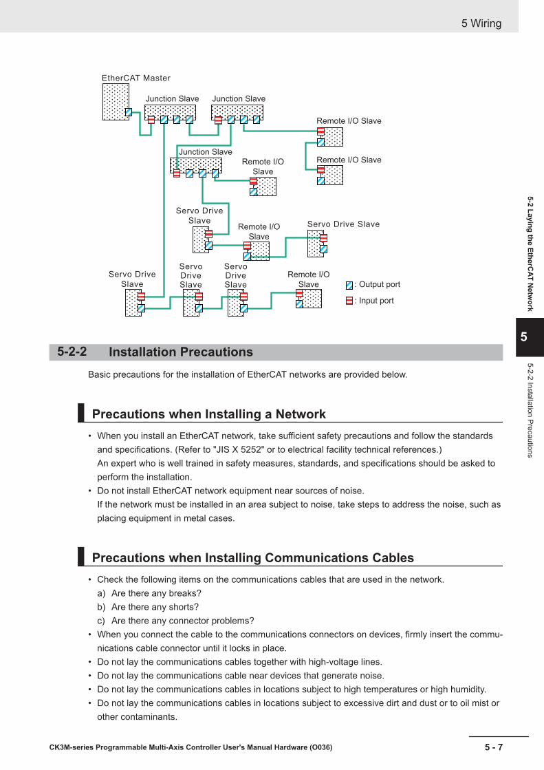
EtherCAT Master
Junction Slave Junction Slave
Junction Slave
Remote I/O Slave
Remote I/O SlaveRemote I/O
Slave
Remote I/O
Slave
Remote I/O
Slave
Servo Drive
Slave
Servo Drive
Slave
Servo Drive Slave
Servo Drive Slave
Servo Drive Slave
: Output port
: Input port
5-2-2 Installation PrecautionsBasic precautions for the installation of EtherCAT networks are provided below.
Precautions when Installing a Network• When you install an EtherCAT network, take sufficient safety precautions and follow the standards
and specifications. (Refer to "JIS X 5252" or to electrical facility technical references.)An expert who is well trained in safety measures, standards, and specifications should be asked toperform the installation.
• Do not install EtherCAT network equipment near sources of noise.If the network must be installed in an area subject to noise, take steps to address the noise, such asplacing equipment in metal cases.
Precautions when Installing Communications Cables• Check the following items on the communications cables that are used in the network.
a) Are there any breaks?b) Are there any shorts?c) Are there any connector problems?
• When you connect the cable to the communications connectors on devices, firmly insert the commu-nications cable connector until it locks in place.
• Do not lay the communications cables together with high-voltage lines.• Do not lay the communications cable near devices that generate noise.• Do not lay the communications cables in locations subject to high temperatures or high humidity.• Do not lay the communications cables in locations subject to excessive dirt and dust or to oil mist or
other contaminants.
5 Wiring
5 - 7CK3M-series Programmable Multi-Axis Controller User's Manual Hardware (O036)
5-2 Laying the EtherCAT N
etwork
5
5-2-2 Installation Precautions

• There are limitations on the bending radius of communications cables. Check the specifications ofthe communications cable for the bending radius.
5-2-3 Installing EtherCAT Communications CablesEthernet communications cables and connectors are used to connect the EtherCAT port of the CPUUnit with EtherCAT slaves.Use a straight, shielded twisted-pair cable (double shielding with aluminum tape and braiding) ofEthernet category 5 (100BASE-TX) or higher. The following products are recommended.
Cable with Connectors
Sizes and Conductor Pairs: AWG 27 × 4 Pairs
Product name Manufac-turer
Cablelength (m)
*1Model Contact informa-
tion
Cable with Connectors onBoth Ends(RJ45/RJ45)Standard RJ45 connectortype
OMRONCorpora-tion
0.3 XS6W-6LSZH8SS30CM-Y *2
OMRON CustomerService Center
0.5 XS6W-6LSZH8SS50CM-Y *2
1 XS6W-6LSZH8SS100CM-Y *2
10 XS6W-6LSZH8SS1000CM-Y *2
*1. For the latest list of the Cables, refer to the Industrial Ethernet Connectors Catalog (Cat. No. G019).*2. The Cables are single-shielded, but the communications and noise characteristics are ensured to satisfy
the standard values.
5 Wiring
5 - 8 CK3M-series Programmable Multi-Axis Controller User's Manual Hardware (O036)
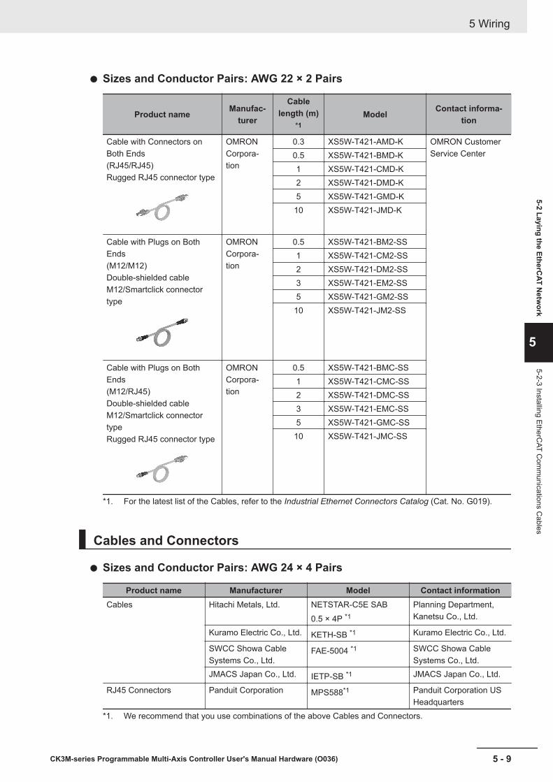
Sizes and Conductor Pairs: AWG 22 × 2 Pairs
Product name Manufac-turer
Cablelength (m)
*1Model Contact informa-
tion
Cable with Connectors onBoth Ends(RJ45/RJ45)Rugged RJ45 connector type
OMRONCorpora-tion
0.3 XS5W-T421-AMD-K OMRON CustomerService Center0.5 XS5W-T421-BMD-K
1 XS5W-T421-CMD-K2 XS5W-T421-DMD-K5 XS5W-T421-GMD-K10 XS5W-T421-JMD-K
Cable with Plugs on BothEnds(M12/M12)Double-shielded cableM12/Smartclick connectortype
OMRONCorpora-tion
0.5 XS5W-T421-BM2-SS1 XS5W-T421-CM2-SS2 XS5W-T421-DM2-SS3 XS5W-T421-EM2-SS5 XS5W-T421-GM2-SS
10 XS5W-T421-JM2-SS
Cable with Plugs on BothEnds(M12/RJ45)Double-shielded cableM12/Smartclick connectortypeRugged RJ45 connector type
OMRONCorpora-tion
0.5 XS5W-T421-BMC-SS1 XS5W-T421-CMC-SS2 XS5W-T421-DMC-SS3 XS5W-T421-EMC-SS5 XS5W-T421-GMC-SS
10 XS5W-T421-JMC-SS
*1. For the latest list of the Cables, refer to the Industrial Ethernet Connectors Catalog (Cat. No. G019).
Cables and Connectors
Sizes and Conductor Pairs: AWG 24 × 4 Pairs
Product name Manufacturer Model Contact informationCables Hitachi Metals, Ltd. NETSTAR-C5E SAB
0.5 × 4P *1Planning Department,Kanetsu Co., Ltd.
Kuramo Electric Co., Ltd. KETH-SB *1 Kuramo Electric Co., Ltd.
SWCC Showa CableSystems Co., Ltd.
FAE-5004 *1 SWCC Showa CableSystems Co., Ltd.
JMACS Japan Co., Ltd. IETP-SB *1 JMACS Japan Co., Ltd.
RJ45 Connectors Panduit Corporation MPS588*1 Panduit Corporation USHeadquarters
*1. We recommend that you use combinations of the above Cables and Connectors.
5 Wiring
5 - 9CK3M-series Programmable Multi-Axis Controller User's Manual Hardware (O036)
5-2 Laying the EtherCAT N
etwork
5
5-2-3 Installing EtherCAT C
omm
unications Cables

Sizes and Conductor Pairs: AWG 22 × 2 Pairs
Product name Manufacturer Model Contact informationCables Kuramo Electric Co., Ltd. KETH-PSB-OMR *1 Kuramo Electric Co., Ltd.
SWCC Showa CableSystems Co., Ltd.
FAE-5002 *1 SWCC Showa CableSystems Co., Ltd.
JMACS Japan Co., Ltd. PNET/B *1 JMACS Japan Co., Ltd.
RJ45 Assembly Connec-tors
OMRON Corporation XS6G-T421-1 *1 OMRON Customer Serv-ice Center
*1. We recommend that you use combinations of the above Cables and Connectors.
Attaching the Connectors to the Cable and Pin AssignmentsUse straight wiring to attach the connectors to the communications cable, as shown below.
Pin No.
1
2
3
4
5
6
7
8
Hood
Pin No.
1
2
3
4
5
6
7
8
Hood
Wire color
White-Green
Green
White-Orange
Blue
White-Blue
Orange
White-Brown
Brown
Shield
Wire color
White-Green
Green
White-Orange
Blue
White-Blue
Orange
White-Brown
Brown
Shield
Note 1. Connect the cable shield to the connector hood at both ends of the cable.Note 2. There are two connection methods for Ethernet: T568A and T568B. The T568A connection method is
shown above, but the T568B connection method can also be used.
Connector Specifications
Item SpecificationElectrical characteristics Conforms to IEEE 802.3 standards.Connector structure RJ45 8-pin modular connector (Conforms to ISO 8877)
Pin Assignments
8
1
Pin No. Signal name Abbreviation Signal direction1 Transmission data + TD+ Output2 Transmission data − TD− Output3 Reception data + RD+ Input
5 Wiring
5 - 10 CK3M-series Programmable Multi-Axis Controller User's Manual Hardware (O036)

Pin No. Signal name Abbreviation Signal direction4 Not used. --- ---5 Not used. --- ---6 Reception data − RD− Input7 Not used. --- ---8 Not used. --- ---
Hood Frame ground FG ---
5 Wiring
5 - 11CK3M-series Programmable Multi-Axis Controller User's Manual Hardware (O036)
5-2 Laying the EtherCAT N
etwork
5
5-2-3 Installing EtherCAT C
omm
unications Cables

5-3 Laying the Ethernet Network
5-3-1 Installation PrecautionsBasic precautions for the installation of Ethernet networks are provided below.
Precautions when Installing a Network• When you install an Ethernet network, take sufficient safety precautions and follow the standards
and specifications. (Refer to "JIS X 5252" or to electrical facility technical references.)An expert who is well trained in safety measures, standards, and specifications should be asked toperform the installation.
• Do not install Ethernet network equipment near sources of noise.If the network must be installed in an area subject to noise, take steps to address the noise, such asplacing equipment in metal cases.
Precautions when Installing Communications Cables• Check the following items on the communications cables that are used in the network.
a) Are there any breaks?b) Are there any shorts?c) Are there any connector problems?
• When you connect the cable to the communications connectors on devices, firmly insert the commu-nications cable connector until it locks in place.
• Do not lay the communications cables together with high-voltage lines.• Do not lay the communications cable near devices that generate noise.• Do not lay the communications cables in locations subject to high temperatures or high humidity.• Do not lay the communications cables in locations subject to excessive dirt and dust or to oil mist or
other contaminants.• There are limitations on the bending radius of communications cables. Check the specifications of
the communications cable for the bending radius.
5-3-2 Installing Ethernet NetworksThe following products are recommended as devices to be used to configure an Ethernet network.
Ethernet Switches
Manufacturer Model Function Number ofports
OMRON Corporation W4S1-03B Priority control (QoS): Control data of Ether-Net/IP is prioritized.Failure detection: Broadcast storm, LSI errordetection, 10/100BASE-TX, Auto-Negotiation
3W4S1-05B 5W4S1-05C
Cisco Systems Inc. Contact the manufacturer.
5 Wiring
5 - 12 CK3M-series Programmable Multi-Axis Controller User's Manual Hardware (O036)
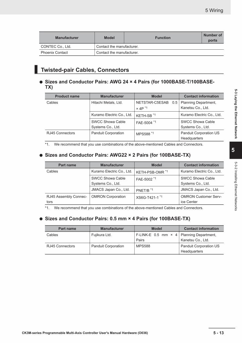
Manufacturer Model Function Number ofports
CONTEC Co., Ltd. Contact the manufacturer.Phoenix Contact Contact the manufacturer.
Twisted-pair Cables, Connectors
Sizes and Conductor Pairs: AWG 24 × 4 Pairs (for 1000BASE-T/100BASE-TX)
Product name Manufacturer Model Contact informationCables Hitachi Metals, Ltd. NETSTAR-C5ESAB 0.5
× 4P *1Planning Department,Kanetsu Co., Ltd.
Kuramo Electric Co., Ltd. KETH-SB *1 Kuramo Electric Co., Ltd.
SWCC Showa CableSystems Co., Ltd.
FAE-5004 *1 SWCC Showa CableSystems Co., Ltd.
RJ45 Connectors Panduit Corporation MPS588 *1 Panduit Corporation USHeadquarters
*1. We recommend that you use combinations of the above-mentioned Cables and Connectors.
Sizes and Conductor Pairs: AWG22 × 2 Pairs (for 100BASE-TX)
Part name Manufacturer Model Contact informationCables Kuramo Electric Co., Ltd. KETH-PSB-OMR *1 Kuramo Electric Co., Ltd.
SWCC Showa CableSystems Co., Ltd.
FAE-5002 *1 SWCC Showa CableSystems Co., Ltd.
JMACS Japan Co., Ltd. PNET/B *1 JMACS Japan Co., Ltd.
RJ45 Assembly Connec-tors
OMRON Corporation XS6G-T421-1 *1 OMRON Customer Serv-ice Center
*1. We recommend that you use combinations of the above-mentioned Cables and Connectors.
Sizes and Conductor Pairs: 0.5 mm × 4 Pairs (for 100BASE-TX)
Part name Manufacturer Model Contact informationCables Fujikura Ltd. F-LINK-E 0.5 mm × 4
PairsPlanning Department,Kanetsu Co., Ltd.
RJ45 Connectors Panduit Corporation MPS588 Panduit Corporation USHeadquarters
5 Wiring
5 - 13CK3M-series Programmable Multi-Axis Controller User's Manual Hardware (O036)
5-3 Laying the Ethernet Netw
ork
5
5-3-2 Installing Ethernet Netw
orks
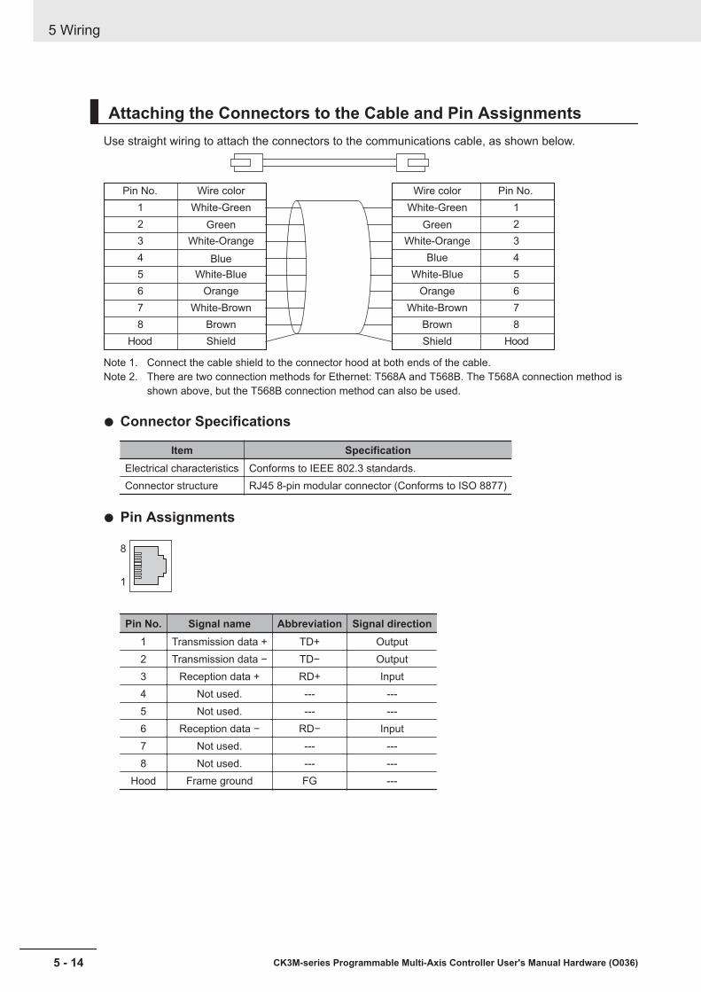
Attaching the Connectors to the Cable and Pin AssignmentsUse straight wiring to attach the connectors to the communications cable, as shown below.
Pin No.
1
2
3
4
5
6
7
8
Hood
Pin No.
1
2
3
4
5
6
7
8
Hood
Wire color
White-Green
Green
White-Orange
Blue
White-Blue
Orange
White-Brown
Brown
Shield
Wire color
White-Green
Green
White-Orange
Blue
White-Blue
Orange
White-Brown
Brown
Shield
Note 1. Connect the cable shield to the connector hood at both ends of the cable.Note 2. There are two connection methods for Ethernet: T568A and T568B. The T568A connection method is
shown above, but the T568B connection method can also be used.
Connector Specifications
Item SpecificationElectrical characteristics Conforms to IEEE 802.3 standards.Connector structure RJ45 8-pin modular connector (Conforms to ISO 8877)
Pin Assignments
8
1
Pin No. Signal name Abbreviation Signal direction1 Transmission data + TD+ Output2 Transmission data − TD− Output3 Reception data + RD+ Input4 Not used. --- ---5 Not used. --- ---6 Reception data − RD− Input7 Not used. --- ---8 Not used. --- ---
Hood Frame ground FG ---
5 Wiring
5 - 14 CK3M-series Programmable Multi-Axis Controller User's Manual Hardware (O036)
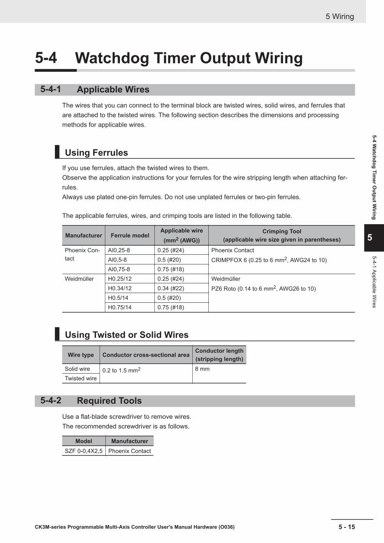
5-4 Watchdog Timer Output Wiring
5-4-1 Applicable WiresThe wires that you can connect to the terminal block are twisted wires, solid wires, and ferrules thatare attached to the twisted wires. The following section describes the dimensions and processingmethods for applicable wires.
Using FerrulesIf you use ferrules, attach the twisted wires to them.Observe the application instructions for your ferrules for the wire stripping length when attaching fer-rules.Always use plated one-pin ferrules. Do not use unplated ferrules or two-pin ferrules.
The applicable ferrules, wires, and crimping tools are listed in the following table.
Manufacturer Ferrule modelApplicable wire
(mm2 (AWG))Crimping Tool
(applicable wire size given in parentheses)
Phoenix Con-tact
AI0,25-8 0.25 (#24) Phoenix ContactCRIMPFOX 6 (0.25 to 6 mm2, AWG24 to 10)AI0,5-8 0.5 (#20)
AI0,75-8 0.75 (#18)Weidmüller H0.25/12 0.25 (#24) Weidmüller
PZ6 Roto (0.14 to 6 mm2, AWG26 to 10)H0.34/12 0.34 (#22)H0.5/14 0.5 (#20)H0.75/14 0.75 (#18)
Using Twisted or Solid Wires
Wire type Conductor cross-sectional area Conductor length(stripping length)
Solid wire 0.2 to 1.5 mm2 8 mmTwisted wire
5-4-2 Required ToolsUse a flat-blade screwdriver to remove wires.The recommended screwdriver is as follows.
Model ManufacturerSZF 0-0,4X2,5 Phoenix Contact
5 Wiring
5 - 15CK3M-series Programmable Multi-Axis Controller User's Manual Hardware (O036)
5-4 Watchdog Tim
er Output W
iring
5
5-4-1 Applicable Wires

5-4-3 Connecting FerrulesInsert the ferrule straight into the terminal hole.It is not necessary to press a flat-blade screwdriver into the release hole.
Ferrule
After you make a connection, make sure that the ferrule is securely connected to the terminal block.
5-4-4 Connecting Twisted Wires/Solid WiresUse the following procedure to connect the twisted wires or solid wires to the terminal block.
1 Press a flat-blade screwdriver straight into the release hole.If you press in the screwdriver correctly, you will feel the spring in the release hole, and thescrew driver will begin to incline.
Release hole
Flat-blade screwdriver
1
2 Leave the flat-blade screwdriver pressed into the release hole and insert the twisted wire or thesolid wire into the terminal hole.Insert the twisted wire or the solid wire until the stripped portion is no longer visible to preventshorting.
2
Twisted wire/Solid wire
3 Remove the flat-blade screwdriver from the release hole.
3
5 Wiring
5 - 16 CK3M-series Programmable Multi-Axis Controller User's Manual Hardware (O036)
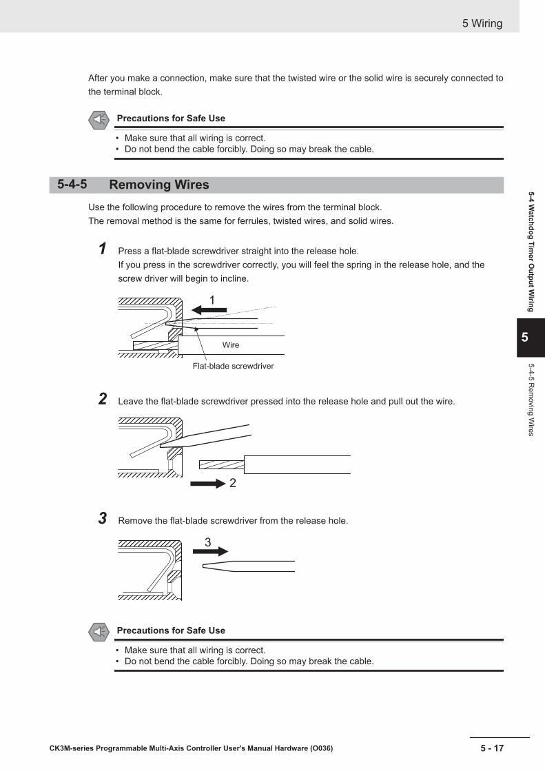
After you make a connection, make sure that the twisted wire or the solid wire is securely connected tothe terminal block.
Precautions for Safe Use
• Make sure that all wiring is correct.• Do not bend the cable forcibly. Doing so may break the cable.
5-4-5 Removing WiresUse the following procedure to remove the wires from the terminal block.The removal method is the same for ferrules, twisted wires, and solid wires.
1 Press a flat-blade screwdriver straight into the release hole.If you press in the screwdriver correctly, you will feel the spring in the release hole, and thescrew driver will begin to incline.
1
Wire
Flat-blade screwdriver
2 Leave the flat-blade screwdriver pressed into the release hole and pull out the wire.
2
3 Remove the flat-blade screwdriver from the release hole.
3
Precautions for Safe Use
• Make sure that all wiring is correct.• Do not bend the cable forcibly. Doing so may break the cable.
5 Wiring
5 - 17CK3M-series Programmable Multi-Axis Controller User's Manual Hardware (O036)
5-4 Watchdog Tim
er Output W
iring
5
5-4-5 Rem
oving Wires

5-5 USB Memory Device ConnectionConnect a USB memory device to the USB host port (Type A) on the CPU Unit to save relevant data.Refer to 3-1-5 USB Memory Device on page 3 - 7 for information on the recommended USB memorydevices.
5 Wiring
5 - 18 CK3M-series Programmable Multi-Axis Controller User's Manual Hardware (O036)

5-6 Encoder Connector Wiring
5-6-1 Connector ArrangementThe Unit side connector is a high-density D-sub 15-pin female (MIL-C-24308 compliant) connector.
5 1
6
1115
10
PinNo. Symbol
Digital Quadrature Encod-er
+ UVW signalSerial Encoder Digital Quadrature Encoder
+ Serial Encoder
1 CHA Encoder A+ Input Not wired - Encoder A+ Input2 CHB Encoder B+ Input Not wired - Encoder B+ Input3 CHC Encoder C+ Input Not wired - Encoder C+ Input4 CHU Hall sensor U Input Serial Encoder
CLK+Output Serial Encoder
CLK+Output
5 CHW Hall sensor W Input Serial EncoderDAT+
Input /Output
Serial EncoderDAT+
Input /Output
6 CHA/ Encoder A- Input Not wired - Encoder A- Input7 CHB/ Encoder B- Input Not wired - Encoder B- Input8 CHC/ Encoder C- Input Not wired - Encoder C- Input9 CHV Hall sensor V Input Serial Encoder
CLK-Output Serial Encoder
CLK+Output
10 CHT Hall sensor T Input Serial EncoderDAT-
Input /Output
Serial EncoderDAT+
Input /Output
11 ENCPWR Encoder PowerSupply (+5VDC)
Output Encoder Pow-er Supply (+5VDC)
Output Encoder PowerSupply (+5 VDC)
Output
12 ENCPWR Encoder PowerSupply (+5VDC)
Output Encoder Pow-er Supply (+5VDC)
Output Encoder PowerSupply (+5 VDC)
Output
13 GND Encoder PowerSupply (GND)
Common Encoder Pow-er Supply(GND)
Common Encoder PowerSupply (GND)
Common
14 GND Encoder PowerSupply (GND)
Common Encoder Pow-er Supply(GND)
Common Encoder PowerSupply (GND)
Common
15 OutFlagB OutFlagB Output OutFlagB Output OutFlagB OutputShell SHELL Shield Shield Shield
5 Wiring
5 - 19CK3M-series Programmable Multi-Axis Controller User's Manual Hardware (O036)
5-6 Encoder Connector W
iring
5
5-6-1 Connector Arrangem
ent
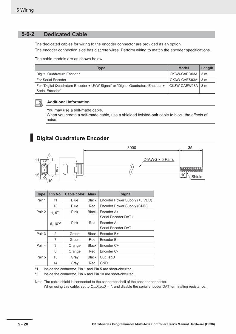
5-6-2 Dedicated CableThe dedicated cables for wiring to the encoder connector are provided as an option.The encoder connection side has discrete wires. Perform wiring to match the encoder specifications.
The cable models are as shown below.
Type Model LengthDigital Quadrature Encoder CK3W-CAED03A 3 mFor Serial Encoder CK3W-CAES03A 3 mFor "Digital Quadrature Encoder + UVW Signal" or "Digital Quadrature Encoder +Serial Encoder"
CK3W-CAEW03A 3 m
Additional Information
You may use a self-made cable.When you create a self-made cable, use a shielded twisted-pair cable to block the effects ofnoise.
Digital Quadrature Encoder
10
3000 35
24AWG x 5 Pairs
6
1
5
10
15
11
Shield
Type Pin No. Cable color Mark SignalPair 1 11 Blue Black Encoder Power Supply (+5 VDC)
13 Blue Red Encoder Power Supply (GND)Pair 2 1, 5*1 Pink Black Encoder A+
Serial Encoder DAT+
6, 10*2 Pink Red Encoder A-Serial Encoder DAT-
Pair 3 2 Green Black Encoder B+7 Green Red Encoder B-
Pair 4 3 Orange Black Encoder C+8 Orange Red Encoder C-
Pair 5 15 Gray Black OutFlagB14 Gray Red GND
*1. Inside the connector, Pin 1 and Pin 5 are short-circuited.*2. Inside the connector, Pin 6 and Pin 10 are short-circuited.
Note The cable shield is connected to the connector shell of the encoder connector.When using this cable, set to OutFlagD = 1, and disable the serial encoder DAT terminating resistance.
5 Wiring
5 - 20 CK3M-series Programmable Multi-Axis Controller User's Manual Hardware (O036)
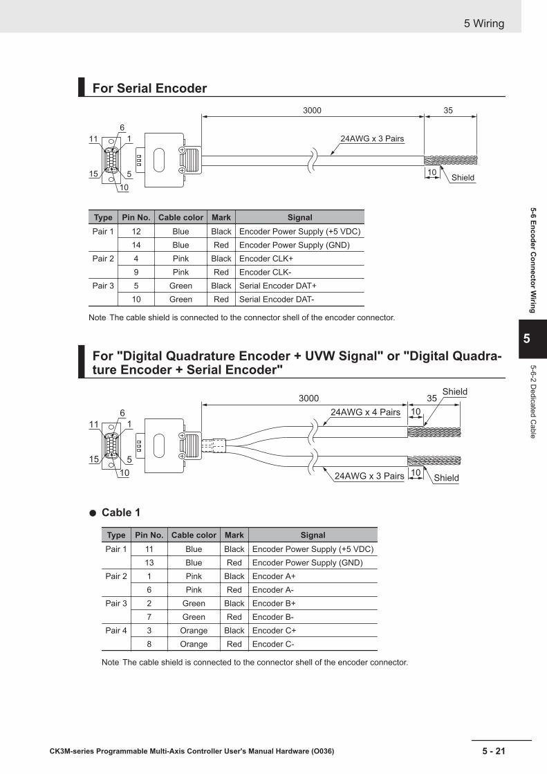
For Serial Encoder
Shield10
3000 35
24AWG x 3 Pairs
6
1
5
10
15
11
Type Pin No. Cable color Mark SignalPair 1 12 Blue Black Encoder Power Supply (+5 VDC)
14 Blue Red Encoder Power Supply (GND)Pair 2 4 Pink Black Encoder CLK+
9 Pink Red Encoder CLK-Pair 3 5 Green Black Serial Encoder DAT+
10 Green Red Serial Encoder DAT-
Note The cable shield is connected to the connector shell of the encoder connector.
For "Digital Quadrature Encoder + UVW Signal" or "Digital Quadra-ture Encoder + Serial Encoder"
3000 35
10
10
24AWG x 4 Pairs
24AWG x 3 Pairs
6
1
5
10
15
11
Shield
Shield
Cable 1
Type Pin No. Cable color Mark SignalPair 1 11 Blue Black Encoder Power Supply (+5 VDC)
13 Blue Red Encoder Power Supply (GND)Pair 2 1 Pink Black Encoder A+
6 Pink Red Encoder A-Pair 3 2 Green Black Encoder B+
7 Green Red Encoder B-Pair 4 3 Orange Black Encoder C+
8 Orange Red Encoder C-
Note The cable shield is connected to the connector shell of the encoder connector.
5 Wiring
5 - 21CK3M-series Programmable Multi-Axis Controller User's Manual Hardware (O036)
5-6 Encoder Connector W
iring
5
5-6-2 Dedicated C
able

Cable 2
Type Pin No. Cable color MarkSignal
U, V, W Serial EncoderPair 1 12 Blue Black Encoder Power Supply (+5 VDC)
14 Blue Red Encoder Power Supply (GND)Pair 2 4 Pink Black Hall sensor U Serial Encoder CLK+
9 Pink Red Hall sensor V Serial Encoder CLK-Pair 3 5 Green Black Hall sensor W Serial Encoder DAT+
10 Green Red Hall sensor T Serial Encoder DAT-
Note The cable shield is connected to the connector shell of the encoder connector.
5 Wiring
5 - 22 CK3M-series Programmable Multi-Axis Controller User's Manual Hardware (O036)
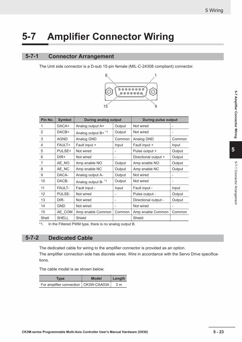
5-7 Amplifier Connector Wiring
5-7-1 Connector ArrangementThe Unit side connector is a D-sub 15-pin female (MIL-C-24308 compliant) connector.
15
8 1
9
Pin No. Symbol During analog output During pulse output1 DACA+ Analog output A+ Output Not wired -2 DACB+ Analog output B+ *1 Output Not wired -
3 AGND Analog GND Common Analog GND Common4 FAULT+ Fault input + Input Fault input + Input5 PULSE+ Not wired - Pulse output + Output6 DIR+ Not wired - Directional output + Output7 AE_NO Amp enable NO Output Amp enable NO Output8 AE_NC Amp enable NC Output Amp enable NC Output9 DACA- Analog output A- Output Not wired -10 DACB- Analog output B- *1 Output Not wired -
11 FAULT- Fault input - Input Fault input - Input12 PULSE- Not wired - Pulse output - Output13 DIR- Not wired - Directional output - Output14 GND Not wired - Not wired -15 AE_COM Amp enable Common Common Amp enable Common CommonShell SHELL Shield Shield
*1. In the Filtered PWM type, there is no analog output B.
5-7-2 Dedicated CableThe dedicated cable for wiring to the amplifier connector is provided as an option.The amplifier connection side has discrete wires. Wire in accordance with the Servo Drive specifica-tions.
The cable model is as shown below.
Type Model LengthFor amplifier connection CK3W-CAA03A 3 m
5 Wiring
5 - 23CK3M-series Programmable Multi-Axis Controller User's Manual Hardware (O036)
5-7 Am
plifier Connector W
iring
5
5-7-1 Connector Arrangem
ent
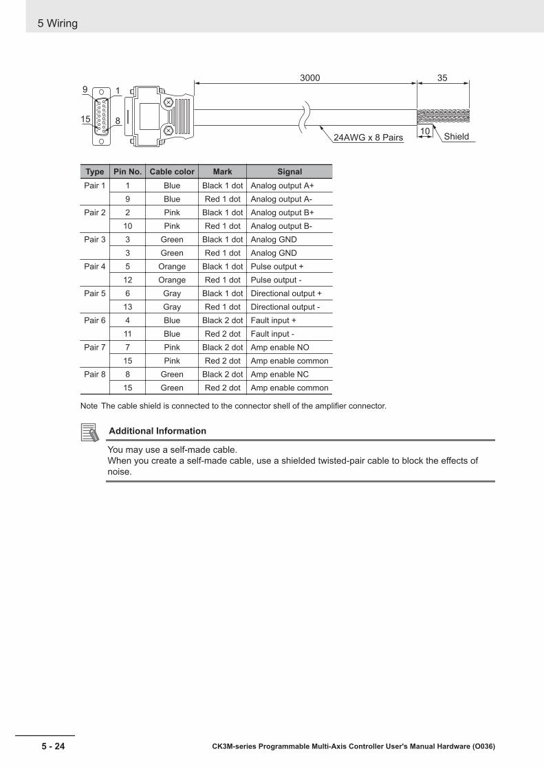
10
3000 35
1
8
9
15
Shield24AWG x 8 Pairs
Type Pin No. Cable color Mark SignalPair 1 1 Blue Black 1 dot Analog output A+
9 Blue Red 1 dot Analog output A-Pair 2 2 Pink Black 1 dot Analog output B+
10 Pink Red 1 dot Analog output B-Pair 3 3 Green Black 1 dot Analog GND
3 Green Red 1 dot Analog GNDPair 4 5 Orange Black 1 dot Pulse output +
12 Orange Red 1 dot Pulse output -Pair 5 6 Gray Black 1 dot Directional output +
13 Gray Red 1 dot Directional output -Pair 6 4 Blue Black 2 dot Fault input +
11 Blue Red 2 dot Fault input -Pair 7 7 Pink Black 2 dot Amp enable NO
15 Pink Red 2 dot Amp enable commonPair 8 8 Green Black 2 dot Amp enable NC
15 Green Red 2 dot Amp enable common
Note The cable shield is connected to the connector shell of the amplifier connector.
Additional Information
You may use a self-made cable.When you create a self-made cable, use a shielded twisted-pair cable to block the effects ofnoise.
5 Wiring
5 - 24 CK3M-series Programmable Multi-Axis Controller User's Manual Hardware (O036)
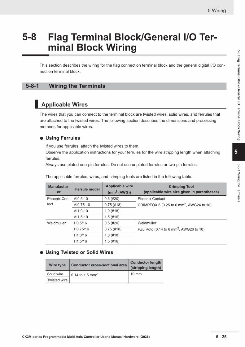
5-8 Flag Terminal Block/General I/O Ter-minal Block Wiring
This section describes the wiring for the flag connection terminal block and the general digital I/O con-nection terminal block.
5-8-1 Wiring the Terminals
Applicable WiresThe wires that you can connect to the terminal block are twisted wires, solid wires, and ferrules thatare attached to the twisted wires. The following section describes the dimensions and processingmethods for applicable wires.
Using FerrulesIf you use ferrules, attach the twisted wires to them.Observe the application instructions for your ferrules for the wire stripping length when attachingferrules.Always use plated one-pin ferrules. Do not use unplated ferrules or two-pin ferrules.
The applicable ferrules, wires, and crimping tools are listed in the following table.
Manufactur-er Ferrule model
Applicable wire(mm2 (AWG))
Crimping Tool(applicable wire size given in parentheses)
Phoenix Con-tact
AI0,5-10 0.5 (#20) Phoenix ContactCRIMPFOX 6 (0.25 to 6 mm2, AWG24 to 10)AI0,75-10 0.75 (#18)
AI1,0-10 1.0 (#18)AI1,5-10 1.5 (#16)
Weidmüller H0.5/16 0.5 (#20) WeidmüllerPZ6 Roto (0.14 to 6 mm2, AWG26 to 10)H0.75/16 0.75 (#18)
H1.0/16 1.0 (#18)H1.5/16 1.5 (#16)
Using Twisted or Solid Wires
Wire type Conductor cross-sectional area Conductor length(stripping length)
Solid wire 0.14 to 1.5 mm2 10 mmTwisted wire
5 Wiring
5 - 25CK3M-series Programmable Multi-Axis Controller User's Manual Hardware (O036)
5-8 Flag Terminal B
lock/General I/O
Terminal B
lock Wiring
5
5-8-1 Wiring the Term
inals

Required ToolsUse a flat-blade screwdriver to remove wires.The recommended screwdriver is as follows.
Model ManufacturerSZF 0-0,4X2,5 Phoenix Contact
Connecting FerrulesInsert the ferrule straight into the terminal hole.It is not necessary to press a flat-blade screwdriver against the release button.
Ferrule
After you make a connection, make sure that the ferrule is securely connected to the terminal block.
Connecting Twisted Wires/Solid WiresUse the following procedure to connect the twisted wires or solid wires to the terminal block.
1 Press a flat-blade screwdriver straight against the release button from the terminal block front.
Release button Flat-blade screwdriver1
2 Leave the flat-blade screwdriver pressed against the release button and insert the twisted wireor the solid wire into the terminal hole.Insert the twisted wire or the solid wire until the stripped portion is no longer visible, to preventshorting.
Twisted wire/Solid wire
Release hole
2
3 Pull the flat-blade screwdriver away from the release button.
5 Wiring
5 - 26 CK3M-series Programmable Multi-Axis Controller User's Manual Hardware (O036)
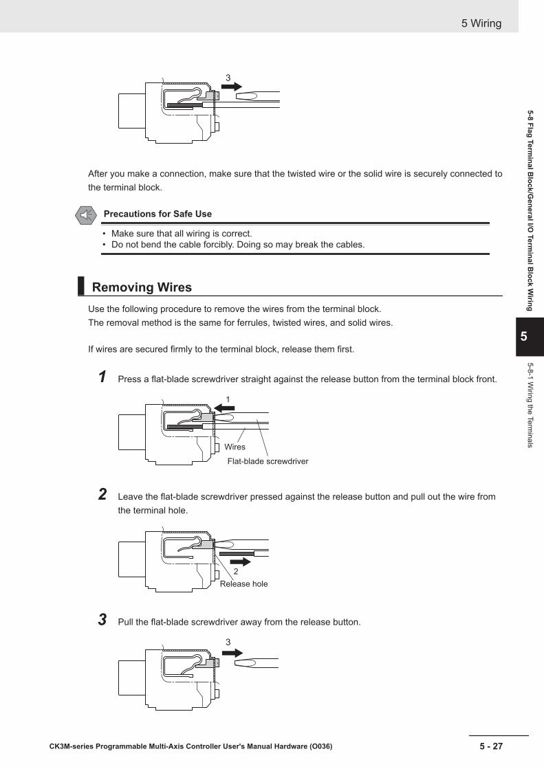
3
After you make a connection, make sure that the twisted wire or the solid wire is securely connected tothe terminal block.
Precautions for Safe Use
• Make sure that all wiring is correct.• Do not bend the cable forcibly. Doing so may break the cables.
Removing WiresUse the following procedure to remove the wires from the terminal block.The removal method is the same for ferrules, twisted wires, and solid wires.
If wires are secured firmly to the terminal block, release them first.
1 Press a flat-blade screwdriver straight against the release button from the terminal block front.
Flat-blade screwdriver
Wires
1
2 Leave the flat-blade screwdriver pressed against the release button and pull out the wire fromthe terminal hole.
Release hole
2
3 Pull the flat-blade screwdriver away from the release button.
3
5 Wiring
5 - 27CK3M-series Programmable Multi-Axis Controller User's Manual Hardware (O036)
5-8 Flag Terminal B
lock/General I/O
Terminal B
lock Wiring
5
5-8-1 Wiring the Term
inals

Precautions for Safe Use
• Make sure that all wiring is correct.• Do not bend the cable forcibly. Doing so may break the cables.
Installing a Terminal BlockInsert the terminal block into the main body, and press hard to click the terminal block into place on theUnit.After you mount the terminal block, make sure that it is fixed to the Unit.
Removing a Terminal BlockDrop the lock levers on both sides of the terminal block at the same time to remove the terminal block.
5-8-2 Precautions When Connecting a Two-wire DC SensorWhen a two-wire sensor is used with a general digital input and a flag input, check that the followingconditions are met.Failure to meet these conditions may result in operating errors.
Relation between ON voltage of the general digital input / flag input andsensor residual voltage
VON ≤ VCC - VR
VON: ON voltage of general digital input and flag input
5 Wiring
5 - 28 CK3M-series Programmable Multi-Axis Controller User's Manual Hardware (O036)

VCC: Input voltage of general digital input and flag input
VR: Output residual voltage of sensor
Relation between input current to the general digital input / flag input andsensor control output (load current)
IOUT (min) ≤ ION ≤ IOUT (max)
Precautions for Correct Use
The general digital input and flag input are constant current type input.For constant current type input, the input current does not increase linearly with the input volt-age.If you gradually raise the input voltage, once the input current reaches ION, the input currentdoes not increase and remains roughly constant even when the input voltage is raised.
When ION is smaller than IOUT (min), connect a bleeder resistor R. The bleeder resistor constant
can be calculated as follows:
R ≤ (VCC - VR) / (IOUT (min) - ION)
Power W of bleeder resistor ≥ (VCC − VR)2 / R × 4 [allowable margin]
VCC: Input voltage of general digital input and flag input
VR: Output residual voltage of sensor
ION: Input current of general digital input and flag input
IOUT: Sensor control output (load current)
Relation between OFF current of the general digital input / flag input andsensor leakage currentThe general digital input and flag input cannot detect sensor output OFF unless the following condi-tions are satisfied:
IOFF ≥ Ileak
When Ileak is greater than IOFF, connect a bleeder resistor R.
Use the following equation to calculate the bleeder resistance constant.
R ≤ (VOFF / IOFF) × VOFF / (Ileak × (VOFF / IOFF) - VOFF)
Power W of bleeder resistor ≥ (VCC − VR)2 / R × 4 [allowable margin]
Two-wire sensorGeneral digital input and flag input
VR
VCC
R
5 Wiring
5 - 29CK3M-series Programmable Multi-Axis Controller User's Manual Hardware (O036)
5-8 Flag Terminal B
lock/General I/O
Terminal B
lock Wiring
5
5-8-2 Precautions When C
onnecting a Two-w
ire DC
Sensor

VCC: Power supply voltage VR: Output residual voltage of sensor
VON: ON voltage of general digital input and flag input IOUT: Sensor control output (load current)
VOFF: OFF voltage of general digital input and flag input Ileak: Sensor leakage current
ION: ON current of general digital input and flag input R: Bleeder resistor
IOFF: OFF current of general digital input and flag input
Precautions for Sensor Inrush CurrentAn incorrect input may occur due to sensor inrush current if a sensor is turned ON after the Unithas started up to the point where inputs are possible.Determine the time required for sensor operation to stabilize after the sensor is turned ON and takeappropriate measures, such as inserting an ON delay into the application program after turning ONthe sensor.
5-8-3 Precautions When Connecting to General Digital Output
Output Short-circuit ProtectionIf a load connected to the output terminals is short-circuited, output components and printed circuitboards may be damaged.When you use a NPN type output that does not include the load short-circuit protection, incorporate aprotective fuse in the output. Use a fuse with a capacity of protection, around twice the rated output.
Precautions for Inrush CurrentWhen you use general digital output, steps must be taken to avoid damage to the output transistorwhen connecting a load with a high inrush current such as an incandescent lamp.Use either of the following methods to reduce the inrush current.
In countermeasure 1, the current consumption from the I/O power supply is increased although thevoltage supplied to the load L is not decreased.In countermeasure 2, the voltage supplied to the load L is decreased although the current consump-tion from the I/O power supply is not increased.Select the appropriate countermeasures according to the operating conditions.
Countermeasure 1Draw about 1/3 of the rated current consumed by the load.
Transistor Output Unit
Transistor Output Unit
NPN type PNP type
OUT
OUTCOM
COM
R R+ +
L
L
5 Wiring
5 - 30 CK3M-series Programmable Multi-Axis Controller User's Manual Hardware (O036)
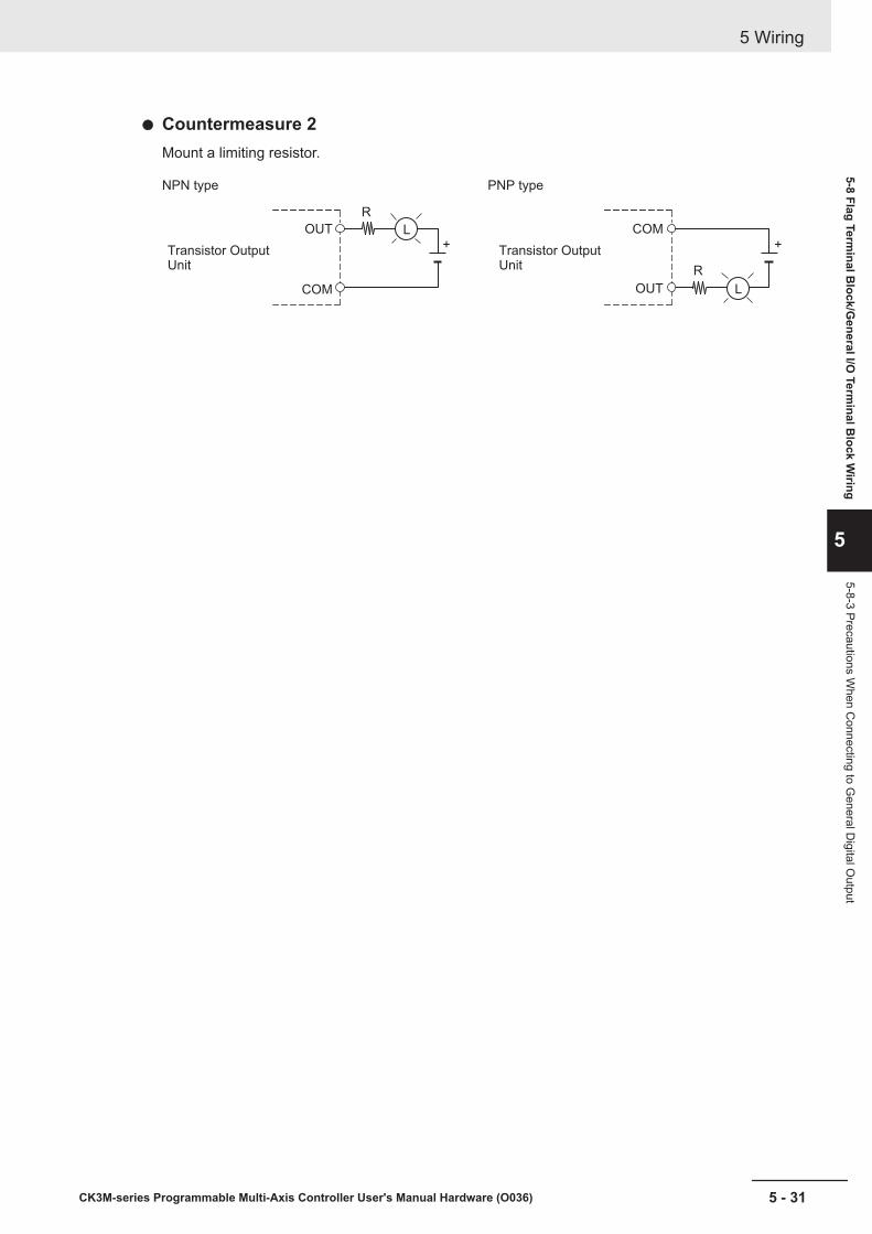
Countermeasure 2Mount a limiting resistor.
Transistor Output Unit
Transistor Output Unit
NPN type PNP type
OUT
COM OUT
COM
R
R
+ +L
L
5 Wiring
5 - 31CK3M-series Programmable Multi-Axis Controller User's Manual Hardware (O036)
5-8 Flag Terminal B
lock/General I/O
Terminal B
lock Wiring
5
5-8-3 Precautions When C
onnecting to General D
igital Output

5 Wiring
5 - 32 CK3M-series Programmable Multi-Axis Controller User's Manual Hardware (O036)
6Troubleshooting
This section describes the confirmation methods and corrections for errors that occurin the CK3M-series Programmable Multi-Axis Controller.
6-1 Types of Errors ............................................................................................. 6 - 26-2 Using the Indicators to Check Errors......................................................... 6 - 3
6-2-1 Indicator Types ............................................................................................. 6 - 36-2-2 Procedure for Identifying Errors.................................................................... 6 - 4
6-3 Troubleshooting for Errors.......................................................................... 6 - 56-3-1 Fatal Errors in the CPU Unit ......................................................................... 6 - 56-3-2 Non-fatal errors in the CPU Unit ................................................................... 6 - 66-3-3 Initialization of CPU Unit Using USB Memory .............................................. 6 - 8
6-4 Sys.Status Register ..................................................................................... 6 - 96-4-1 Sys.Status Register List................................................................................ 6 - 96-4-2 Details of Flags ........................................................................................... 6 - 10
6 - 1CK3M-series Programmable Multi-Axis Controller User's Manual Hardware (O036)
6
6-1 Types of ErrorsThe errors in the Motion Controller are classified into the following two major categories.
• Fatal errors in the CPU UnitErrors that occurred as the result of the CPU Unit operation stopping.
• Non-fatal errors in the CPU UnitErrors that can be detected and managed by the CPU Unit itself that is still operating.
6 Troubleshooting
6 - 2 CK3M-series Programmable Multi-Axis Controller User's Manual Hardware (O036)
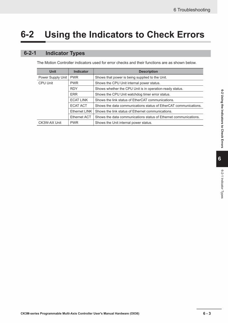
6-2 Using the Indicators to Check Errors
6-2-1 Indicator TypesThe Motion Controller indicators used for error checks and their functions are as shown below.
Unit Indicator DescriptionPower Supply Unit PWR Shows that power is being supplied to the Unit.CPU Unit PWR Shows the CPU Unit internal power status.
RDY Shows whether the CPU Unit is in operation-ready status.ERR Shows the CPU Unit watchdog timer error status.ECAT LINK Shows the link status of EtherCAT communications.ECAT ACT Shows the data communications status of EtherCAT communications.Ethernet LINK Shows the link status of Ethernet communications.Ethernet ACT Shows the data communications status of Ethernet communications.
CK3W-AX Unit PWR Shows the Unit internal power status.
6 Troubleshooting
6 - 3CK3M-series Programmable Multi-Axis Controller User's Manual Hardware (O036)
6-2 Using the Indicators to C
heck Errors
6
6-2-1 Indicator Types
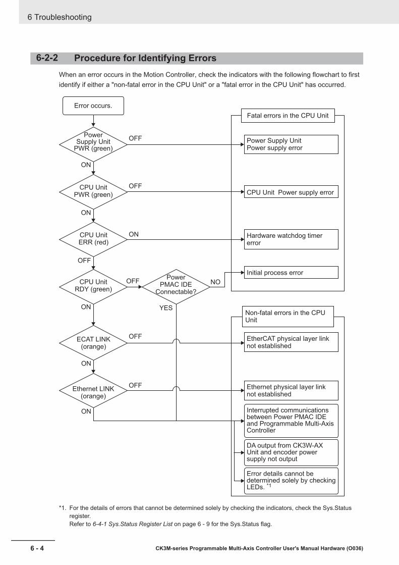
6-2-2 Procedure for Identifying ErrorsWhen an error occurs in the Motion Controller, check the indicators with the following flowchart to firstidentify if either a "non-fatal error in the CPU Unit" or a "fatal error in the CPU Unit" has occurred.
Power Supply Unit
PWR (green)
Error occurs.
OFF
OFF
ON
OFF
OFF
OFF
ON
ON
ON
OFF
ON
ON
CPU UnitPWR (green)
CPU UnitERR (red)
CPU UnitRDY (green)
Power PMAC IDE
Connectable?
ECAT LINK(orange)
Ethernet LINK(orange)
YES
NO
Fatal errors in the CPU Unit
Power Supply UnitPower supply error
CPU Unit Power supply error
Hardware watchdog timer error
Initial process error
EtherCAT physical layer link not established
Ethernet physical layer link not established
DA output from CK3W-AX Unit and encoder power supply not output
Error details cannot be determined solely by checking LEDs. *1
Non-fatal errors in the CPU Unit
Interrupted communications between Power PMAC IDE and Programmable Multi-Axis Controller
*1. For the details of errors that cannot be determined solely by checking the indicators, check the Sys.Statusregister.Refer to 6-4-1 Sys.Status Register List on page 6 - 9 for the Sys.Status flag.
6 Troubleshooting
6 - 4 CK3M-series Programmable Multi-Axis Controller User's Manual Hardware (O036)

6-3 Troubleshooting for Errors
6-3-1 Fatal Errors in the CPU UnitFor fatal errors in the CPU Unit, take the following corrective actions depending on the nature of theerror.
Description Cause Corrective actionPower Supply Unitpower supply error
Power is not suppliedto the Power SupplyUnit
Check the following items and adequately supply power to theunit.• Is the power turned on?• Is the power cable wired correctly?• Is the power cable free of damage?
Input voltage is out ofallowable range
Check the following items and adjust the voltage so that it fallswithin the allowable range.• Is the power supply voltage within the specified range?• Is the capacity of the power supply sufficient?• Is the power supply failing?
Output current of thepower supplied to theencoder exceeds themaximum current ca-pacity
Check the following items and adjust the voltage so that it doesnot exceed the maximum current capacity.• Does encoder current consumption exceed the maximum cur-
rent capacity?• Is the encoder connector wiring connected correctly?• Has the encoder cable short-circuited?• Is the encoder failing?
Power supply error ofmounted unit
Remove the connected Units one by one, and if the error is elimi-nated, replace that Unit.
The number of con-nected Units exceedsthe maximum capaci-ty
Check whether the connected Units exceed the maximum con-nectable number. The maximum connectable number is 2CK3W-AX Units.
Power Supply Unitfailure
If the error persists even after you make the above corrections,replace the Power Supply Unit.
CPU Unit powersupply error
Connection error be-tween the PowerSupply Unit and theCPU Unit
Make sure that the Power Supply Unit and the CPU Unit are con-nected correctly.
CPU Unit or PowerSupply Unit failure
If the error persists even after you make the above corrections,replace the CPU Unit or the Power Supply Unit.
6 Troubleshooting
6 - 5CK3M-series Programmable Multi-Axis Controller User's Manual Hardware (O036)
6-3 Troubleshooting for Errors
6
6-3-1 Fatal Errors in the CPU
Unit
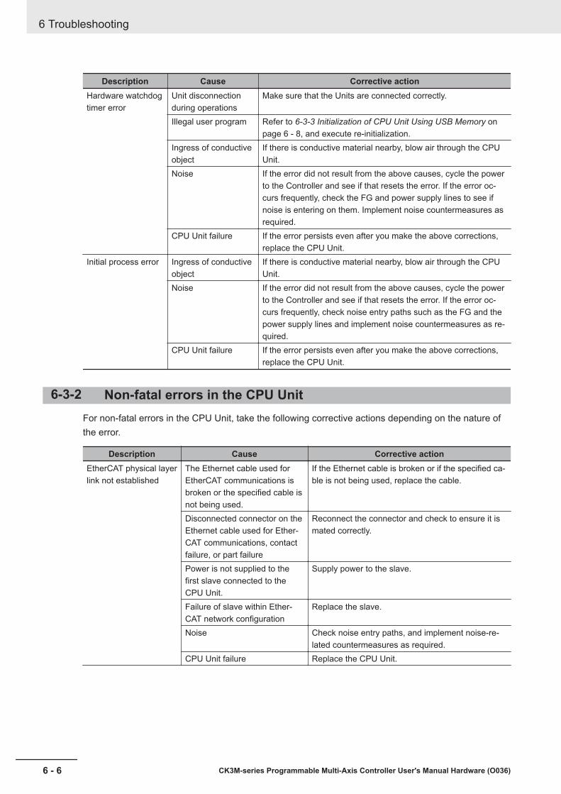
Description Cause Corrective actionHardware watchdogtimer error
Unit disconnectionduring operations
Make sure that the Units are connected correctly.
Illegal user program Refer to 6-3-3 Initialization of CPU Unit Using USB Memory onpage 6 - 8, and execute re-initialization.
Ingress of conductiveobject
If there is conductive material nearby, blow air through the CPUUnit.
Noise If the error did not result from the above causes, cycle the powerto the Controller and see if that resets the error. If the error oc-curs frequently, check the FG and power supply lines to see ifnoise is entering on them. Implement noise countermeasures asrequired.
CPU Unit failure If the error persists even after you make the above corrections,replace the CPU Unit.
Initial process error Ingress of conductiveobject
If there is conductive material nearby, blow air through the CPUUnit.
Noise If the error did not result from the above causes, cycle the powerto the Controller and see if that resets the error. If the error oc-curs frequently, check noise entry paths such as the FG and thepower supply lines and implement noise countermeasures as re-quired.
CPU Unit failure If the error persists even after you make the above corrections,replace the CPU Unit.
6-3-2 Non-fatal errors in the CPU UnitFor non-fatal errors in the CPU Unit, take the following corrective actions depending on the nature ofthe error.
Description Cause Corrective actionEtherCAT physical layerlink not established
The Ethernet cable used forEtherCAT communications isbroken or the specified cable isnot being used.
If the Ethernet cable is broken or if the specified ca-ble is not being used, replace the cable.
Disconnected connector on theEthernet cable used for Ether-CAT communications, contactfailure, or part failure
Reconnect the connector and check to ensure it ismated correctly.
Power is not supplied to thefirst slave connected to theCPU Unit.
Supply power to the slave.
Failure of slave within Ether-CAT network configuration
Replace the slave.
Noise Check noise entry paths, and implement noise-re-lated countermeasures as required.
CPU Unit failure Replace the CPU Unit.
6 Troubleshooting
6 - 6 CK3M-series Programmable Multi-Axis Controller User's Manual Hardware (O036)

Description Cause Corrective actionEthernet physical layerlink not established
The Ethernet cable used forEthernet communications isbroken or the specified cable isnot being used.
If the Ethernet cable is broken or if the specified ca-ble is not being used, replace the cable.
Disconnected connector on theEthernet cable used for Ether-net communications, contactfailure, or part failure
Reconnect the connector and check to ensure it ismated correctly.
Power is not supplied to theEthernet switch connected tothe CPU Unit.
Supply power to the Ethernet switch.
Failure of device within Ether-net network configuration
Replace the device.
Noise Check noise entry paths, and implement noise-re-lated countermeasures as required.
CPU Unit failure Replace the CPU Unit.Interrupted communica-tions between PowerPMAC IDE and CPUUnit
Communications interruption,due to disconnection and re-connection of the Ethernet ca-ble used for Ethernet communi-cation between Power PMACIDE and the CPU Unit whilecommunication was being es-tablished
If communications are interrupted between PowerPMAC IDE and the CPU Unit with Ethernet commu-nications established, communications cannot bereestablished simply by rectifying the problem thatinterrupted the communications. To reestablish thecommunications, you need to clickCommunication Setup in Power PMAC IDE andrestart communications.
Communications interruptiondue to power to Ethernetswitch between Power PMACIDE and CPU Unit being turnedOFF → ON while communica-tions were being establishedCommunications interruptiondue to power to CPU Unit be-ing turned OFF → ON whilecommunications were beingestablishedTemporary communications in-terruption due to noise
Check noise entry paths, and implement noise-re-lated countermeasures as required. Then reestab-lish communications between Power PMAC IDEand the CPU Unit.To reestablish the communications, you need to re-start Power PMAC IDE or reestablish the communi-cations by using Power PMAC IDE.
DA output from CK3W-AX Unit and encoderpower supply not output
Power Supply Unit other thanCK3W-PD048 is being used.
Check the Power Supply Unit model.
CK3W-AX Unit failure Replace the CK3W-AX Unit.Internal 24 V power is not be-ing input to the CK3W-AX Unitdue to a failure of the Unit to itsleft.
Replace the Unit to the left of this Unit.
6 Troubleshooting
6 - 7CK3M-series Programmable Multi-Axis Controller User's Manual Hardware (O036)
6-3 Troubleshooting for Errors
6
6-3-2 Non-fatal errors in the C
PU U
nit

6-3-3 Initialization of CPU Unit Using USB MemoryIf the CPU Unit fails to connect to the Power PMAC IDE, you can use a USB memory to initialize theCPU Unit to the factory state.
Use the following procedure to carry out this process.
1 USB memory preparationPrepare a blank USB memory formatted in FAT32. The recommended USB memory is listed in 3-1-5 USB Memory Device on page 3 - 7.
2 Folder creationUse a computer to create an empty folder named PowerPmacFactoryReset on the USB mem-ory root.
3 With the power OFF, mount the above USB memory to the CPU Unit.
4 When the power to the CPU Unit is turned ON, the CPU Unit will be initialized to the factorydefault.
5 Connect the Power PMAC IDE, and issue a save command.
6 Turn the power OFF, and remove the USB memory.
6 Troubleshooting
6 - 8 CK3M-series Programmable Multi-Axis Controller User's Manual Hardware (O036)

6-4 Sys.Status Register
6-4-1 Sys.Status Register ListIf an error cannot be identified with indicators, the error status can be confirmed in the Sys.Status reg-ister.If an error occurs during operation, check the Sys.Status register with the user program and take suit-able action to avoid dangerous operation.The Sys.Status register is not saved in the built-in flash memory, so it is deleted if the power goesOFF.Sys.Status can be checked using the Power PMAC IDE Status ― Global Status.
The Sys.Status register is 32-bit data with the configuration shown below.
Bit Name Description16-31 -15 CK3WHWChange The CK3W hardware configuration was changed during operation.14 CK3WConfigErr(bit2) There is an error in the CK3W hardware configuration.13 CK3WConfigErr(bit1)12 CK3WConfigErr(bit0)11 FlashSizeErr The user program size exceeds the built-in flash memory capacity.10 BufSizeErr The buffer size exceeds the built-in RAM capacity.9 AbortAll In stop status after Abort all input8 NoClocks Cannot detect a phase clock or a servo clock.7 Default Factory default6 FileConfigErr System file setting error5 HWChangeErr After the save, the hardware configuration was changed.4 ConfigLoadErr Error in saved settings3 ProjectLoadErr User Project File Read Error2 PwrOnFault Read error when power is turned ON or during reset (bit 3 to 6 logical OR)1 WDTFault (bit 1) Real-time interruption software watchdog timer error0 WDTFault (bit 0) Background software watchdog timer error
6 Troubleshooting
6 - 9CK3M-series Programmable Multi-Axis Controller User's Manual Hardware (O036)
6-4 Sys.Status Register
6
6-4-1 Sys.Status Register List

6-4-2 Details of Flags
CK3WHWChange
Register name Sys.CK3WHWChangeDescription The CK3W hardware configuration was changed during operation.Range 0 to 1Details Checks if there were any changes in the configurations of the connected CK3W Unit
and End Cover during operation.0: No changes in hardware configurations during operation1: Changes in hardware configurations during operation
Detection timing ContinuousRecovery Cycle the power supply, reset command ($$$)Effects Operation continuesCause and cor-rection
Cause (Assumed cause) Correction PreventionThe CK3W Unit addressswitch was changed duringoperation.
Check if there were anychanges in the addressswitch.
None
The CK3W Unit or EndCover was disconnectedduring operation.
Make sure that the Unitsare installed correctly.
None
Contamination with conduc-tive object
If there is conductive mate-rial nearby, blow air throughthe Unit.
Do not perform any metalwork in the vicinity of thecontrol panel.Make sure that the work en-vironment is free of dirt anddust.Then close the control pan-el.
Noise• Data corruption in bus
signals• Malfunction of bus inter-
face circuit
If the error occurs even af-ter making the above cor-rection, check noise entrypaths such as the FG andthe power supply lines andimplement noise counter-measures as required.
Implement noise counter-measures.
The CPU Unit or the CK3WUnit has failed• Internal bus contact fail-
ure
If this error persists evenafter you make the abovetwo corrections, replace theCPU Unit or the CK3WUnit.
None
Precautions/Remarks
None
6 Troubleshooting
6 - 10 CK3M-series Programmable Multi-Axis Controller User's Manual Hardware (O036)
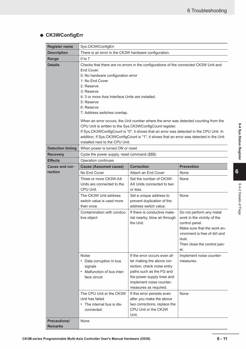
CK3WConfigErr
Register name Sys.CK3WConfigErrDescription There is an error in the CK3W hardware configuration.Range 0 to 7Details Checks that there are no errors in the configurations of the connected CK3W Unit and
End Cover.0: No hardware configuration error1: No End Cover2: Reserve3: Reserve4: 3 or more Axis Interface Units are installed.5: Reserve6: Reserve7: Address switches overlap.
When an error occurs, the Unit number where the error was detected counting from theCPU Unit is written to the Sys.CK3WConfigCount register.If Sys.CK3WConfigCount is "0", it shows that an error was detected in the CPU Unit. Inaddition, if Sys.CK3WConfigCount is "1", it shows that an error was detected in the Unitinstalled next to the CPU Unit.
Detection timing When power is turned ON or resetRecovery Cycle the power supply, reset command ($$$)Effects Operation continuesCause and cor-rection
Cause (Assumed cause) Correction PreventionNo End Cover Attach an End Cover NoneThree or more CK3W-AXUnits are connected to theCPU Unit.
Set the number of CK3W-AX Units connected to twoor less.
None
The CK3W Unit addressswitch value is used morethan once.
Set a unique address toprevent duplication of theaddress switch value.
None
Contamination with conduc-tive object
If there is conductive mate-rial nearby, blow air throughthe Unit.
Do not perform any metalwork in the vicinity of thecontrol panel.Make sure that the work en-vironment is free of dirt anddust.Then close the control pan-el.
Noise• Data corruption in bus
signals• Malfunction of bus inter-
face circuit
If the error occurs even af-ter making the above cor-rection, check noise entrypaths such as the FG andthe power supply lines andimplement noise counter-measures as required.
Implement noise counter-measures.
The CPU Unit or the CK3WUnit has failed• The internal bus is dis-
connected.
If this error persists evenafter you make the abovetwo corrections, replace theCPU Unit or the CK3WUnit.
None
Precautions/Remarks
None
6 Troubleshooting
6 - 11CK3M-series Programmable Multi-Axis Controller User's Manual Hardware (O036)
6-4 Sys.Status Register
6
6-4-2 Details of Flags
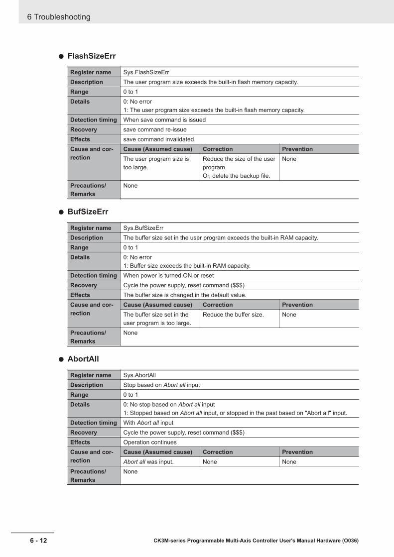
FlashSizeErr
Register name Sys.FlashSizeErrDescription The user program size exceeds the built-in flash memory capacity.Range 0 to 1Details 0: No error
1: The user program size exceeds the built-in flash memory capacity.Detection timing When save command is issuedRecovery save command re-issueEffects save command invalidatedCause and cor-rection
Cause (Assumed cause) Correction PreventionThe user program size istoo large.
Reduce the size of the userprogram.Or, delete the backup file.
None
Precautions/Remarks
None
BufSizeErr
Register name Sys.BufSizeErrDescription The buffer size set in the user program exceeds the built-in RAM capacity.Range 0 to 1Details 0: No error
1: Buffer size exceeds the built-in RAM capacity.Detection timing When power is turned ON or resetRecovery Cycle the power supply, reset command ($$$)Effects The buffer size is changed in the default value.Cause and cor-rection
Cause (Assumed cause) Correction PreventionThe buffer size set in theuser program is too large.
Reduce the buffer size. None
Precautions/Remarks
None
AbortAll
Register name Sys.AbortAllDescription Stop based on Abort all inputRange 0 to 1Details 0: No stop based on Abort all input
1: Stopped based on Abort all input, or stopped in the past based on "Abort all" input.Detection timing With Abort all inputRecovery Cycle the power supply, reset command ($$$)Effects Operation continuesCause and cor-rection
Cause (Assumed cause) Correction PreventionAbort all was input. None None
Precautions/Remarks
None
6 Troubleshooting
6 - 12 CK3M-series Programmable Multi-Axis Controller User's Manual Hardware (O036)

NoClocks
Register name Sys.NoClocksDescription Cannot detect a phase clock or a servo clock.Range 0 to 1Details 0: No error
1: Cannot detect a phase clock or a servo clock.Detection timing When power is turned ON or resetRecovery Cycle the power supply, reset command ($$$)Effects Cannot enable the motor.Cause and cor-rection
Cause (Assumed cause) Correction PreventionThe clock-related register isoverwritten by the user pro-gram.
If the re-initialization com-mand ($$$***) is executed,and the error no longer oc-curs, review the user pro-gram.
None
The CPU Unit or the CK3WUnit has failed
If this error persists evenafter you make the abovecorrections, replace theCPU Unit or the CK3WUnit.
None
Precautions/Remarks
None
Default
Register name Sys.DefaultDescription Initialized to the factory default setting.Range 0 to 1Details 0: No error
1: Cases below
• In the factory default state, or initialized to the factory default state by a re-initializa-tion command ($$$***).
• Configuration changed after save command was issued.Detection timing When power is turned ON or resetRecovery Cycle the power supply, reset command ($$$)Effects Operation continuesCause and cor-rection
Cause (Assumed cause) Correction PreventionRe-initialization command($$$***) issued.
None None
HWChangeErr orConfigLoadErr occurred.
Check the corrective actionfor each error.
None
Precautions/Remarks
None
6 Troubleshooting
6 - 13CK3M-series Programmable Multi-Axis Controller User's Manual Hardware (O036)
6-4 Sys.Status Register
6
6-4-2 Details of Flags
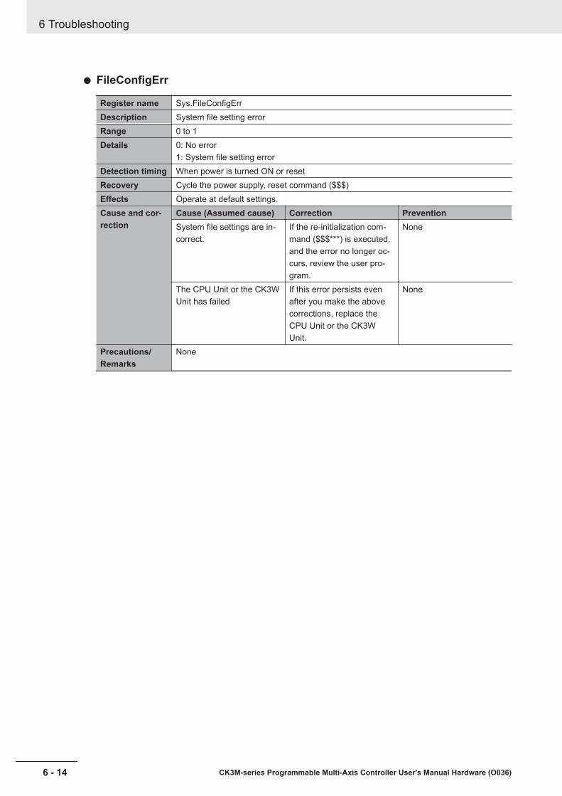
FileConfigErr
Register name Sys.FileConfigErrDescription System file setting errorRange 0 to 1Details 0: No error
1: System file setting errorDetection timing When power is turned ON or resetRecovery Cycle the power supply, reset command ($$$)Effects Operate at default settings.Cause and cor-rection
Cause (Assumed cause) Correction PreventionSystem file settings are in-correct.
If the re-initialization com-mand ($$$***) is executed,and the error no longer oc-curs, review the user pro-gram.
None
The CPU Unit or the CK3WUnit has failed
If this error persists evenafter you make the abovecorrections, replace theCPU Unit or the CK3WUnit.
None
Precautions/Remarks
None
6 Troubleshooting
6 - 14 CK3M-series Programmable Multi-Axis Controller User's Manual Hardware (O036)
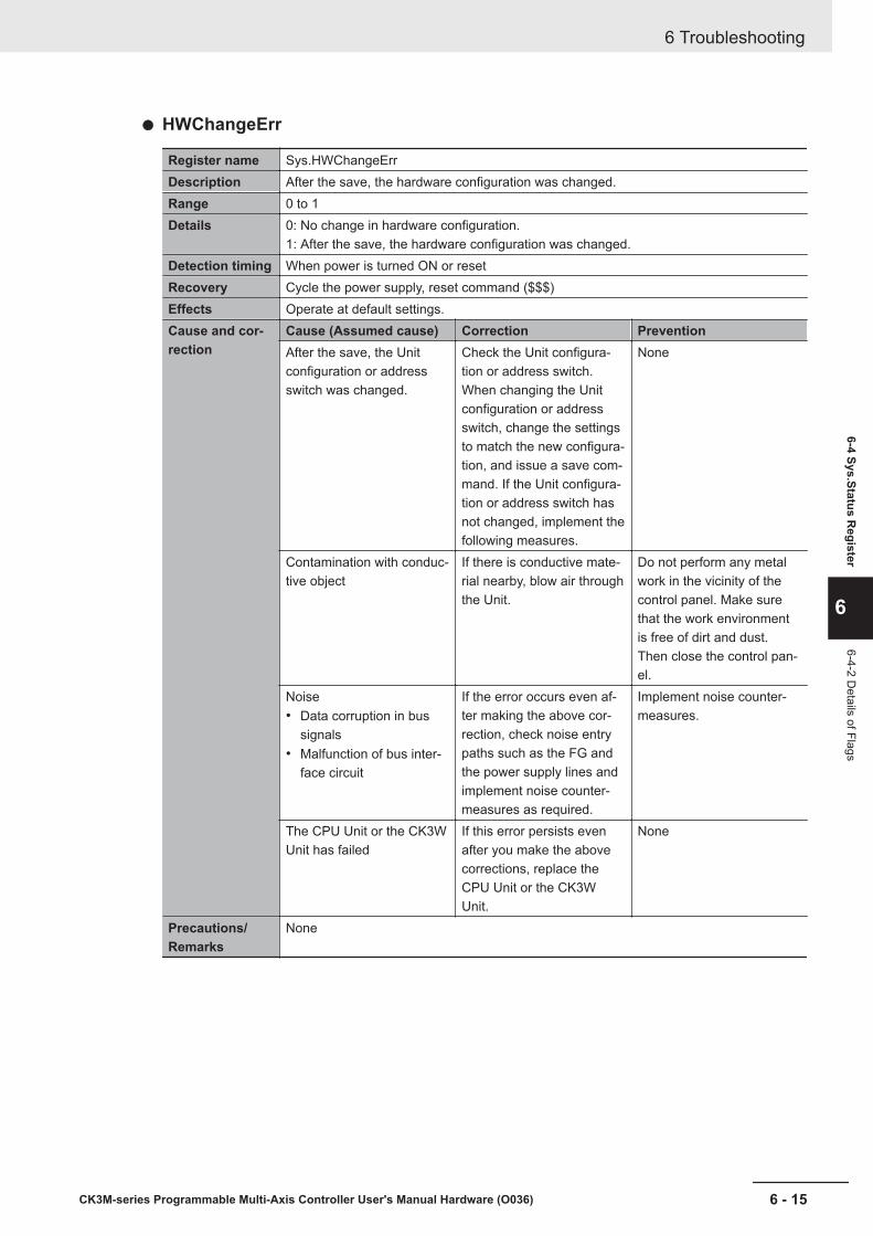
HWChangeErr
Register name Sys.HWChangeErrDescription After the save, the hardware configuration was changed.Range 0 to 1Details 0: No change in hardware configuration.
1: After the save, the hardware configuration was changed.Detection timing When power is turned ON or resetRecovery Cycle the power supply, reset command ($$$)Effects Operate at default settings.Cause and cor-rection
Cause (Assumed cause) Correction PreventionAfter the save, the Unitconfiguration or addressswitch was changed.
Check the Unit configura-tion or address switch.When changing the Unitconfiguration or addressswitch, change the settingsto match the new configura-tion, and issue a save com-mand. If the Unit configura-tion or address switch hasnot changed, implement thefollowing measures.
None
Contamination with conduc-tive object
If there is conductive mate-rial nearby, blow air throughthe Unit.
Do not perform any metalwork in the vicinity of thecontrol panel. Make surethat the work environmentis free of dirt and dust.Then close the control pan-el.
Noise• Data corruption in bus
signals• Malfunction of bus inter-
face circuit
If the error occurs even af-ter making the above cor-rection, check noise entrypaths such as the FG andthe power supply lines andimplement noise counter-measures as required.
Implement noise counter-measures.
The CPU Unit or the CK3WUnit has failed
If this error persists evenafter you make the abovecorrections, replace theCPU Unit or the CK3WUnit.
None
Precautions/Remarks
None
6 Troubleshooting
6 - 15CK3M-series Programmable Multi-Axis Controller User's Manual Hardware (O036)
6-4 Sys.Status Register
6
6-4-2 Details of Flags
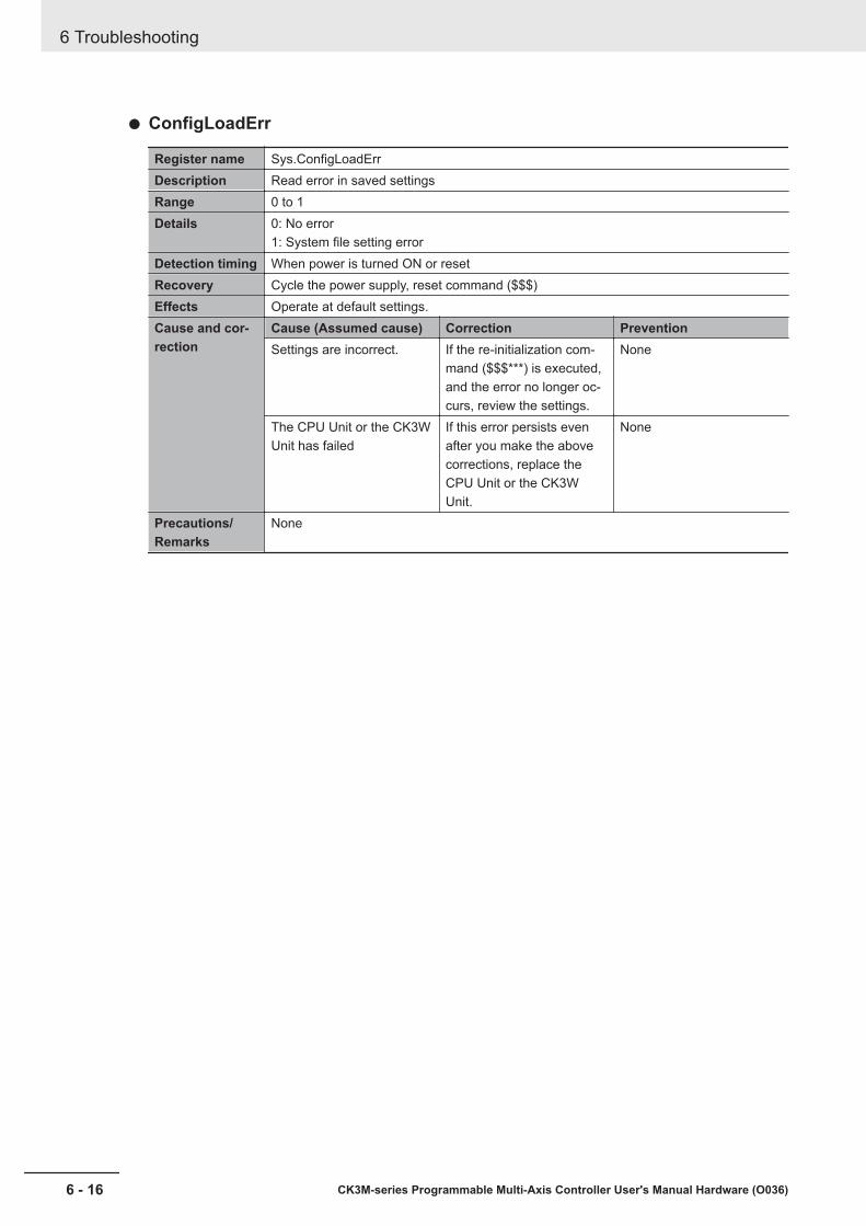
ConfigLoadErr
Register name Sys.ConfigLoadErrDescription Read error in saved settingsRange 0 to 1Details 0: No error
1: System file setting errorDetection timing When power is turned ON or resetRecovery Cycle the power supply, reset command ($$$)Effects Operate at default settings.Cause and cor-rection
Cause (Assumed cause) Correction PreventionSettings are incorrect. If the re-initialization com-
mand ($$$***) is executed,and the error no longer oc-curs, review the settings.
None
The CPU Unit or the CK3WUnit has failed
If this error persists evenafter you make the abovecorrections, replace theCPU Unit or the CK3WUnit.
None
Precautions/Remarks
None
6 Troubleshooting
6 - 16 CK3M-series Programmable Multi-Axis Controller User's Manual Hardware (O036)

ProjectLoadErr
Register name Sys.ProjectLoadErrDescription User Project File Read ErrorRange 0 to 1Details 0: No error
1: User Project File Read ErrorDetection timing When power is turned ON or resetRecovery Cycle the power supply, reset command ($$$), downloadingEffects Operate at default settings.Cause and cor-rection
Cause (Assumed cause) Correction PreventionThe project file is corrupted. After executing the re-initi-
alization command ($$$***), download the projectfile again.
If the unit power supply isturned OFF while savingthe project file, the projectfile may be corrupted.Do not turn OFF the powersupply while saving.
An illegal project file wasdownloaded.
Identify the cause from theoutput window, and makecorrections to the projectfile. After the corrections,execute the re-initializationcommand ($$$***), anddownload the project fileagain.
None
CPU Unit failure If this error persists evenafter you make the abovecorrections, replace theCPU Unit.
None
Precautions/Remarks
None
PwrOnFaultTo ensure that the errors when the power is turned on or during reset can be checked with 1 bit, theSys.PwrOnFault register is set to "1" when any of Sys.FileConfigErr, Sys.HWChangeErr, Sys.Con-figLoadErr, or Sys.ProjectLoadErr is "1".
6 Troubleshooting
6 - 17CK3M-series Programmable Multi-Axis Controller User's Manual Hardware (O036)
6-4 Sys.Status Register
6
6-4-2 Details of Flags
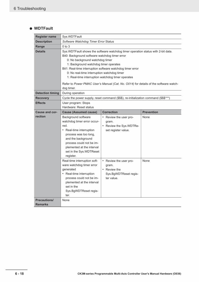
WDTFault
Register name Sys.WDTFaultDescription Software Watchdog Timer Error StatusRange 0 to 3Details Sys.WDTFault shows the software watchdog timer operation status with 2-bit data.
Bit0: Background software watchdog timer error0: No background watchdog timer1: Background watchdog timer operates
Bit1: Real-time interruption software watchdog timer error0: No real-time interruption watchdog timer1: Real-time interruption watchdog timer operates
Refer to Power PMAC User’s Manual (Cat. No. O014) for details of the software watch-dog timer.
Detection timing During operationRecovery Cycle the power supply, reset command ($$$), re-initialization command ($$$***)Effects User program: Stops
Hardware: Reset statusCause and cor-rection
Cause (Assumed cause) Correction PreventionBackground softwarewatchdog timer error occur-red.• Real-time interruption
process was too long,and the backgroundprocess could not be im-plemented at the intervalset in the Sys.WDTResetregister.
• Review the user pro-gram.
• Review the Sys.WDTRe-set register value.
None
Real-time interruption soft-ware watchdog timer errorgenerated• Real-time interruption
process could not be im-plemented at the intervalset in theSys.BgWDTReset regis-ter.
• Review the user pro-gram.
• Review theSys.BgWDTReset regis-ter value.
None
Precautions/Remarks
None
6 Troubleshooting
6 - 18 CK3M-series Programmable Multi-Axis Controller User's Manual Hardware (O036)
7Inspection and Maintenance
This section describes the cleaning, inspection, and maintenance of the CK3M-seriesProgrammable Multi-Axis Controller.
7-1 Cleaning and Maintenance.......................................................................... 7 - 27-1-1 Cleaning........................................................................................................ 7 - 27-1-2 Periodic Inspections...................................................................................... 7 - 2
7-2 Maintenance Procedures............................................................................. 7 - 47-2-1 Unit Replacement Precautions ..................................................................... 7 - 47-2-2 Backup.......................................................................................................... 7 - 47-2-3 Unit Replacement ......................................................................................... 7 - 4
7 - 1CK3M-series Programmable Multi-Axis Controller User's Manual Hardware (O036)
7
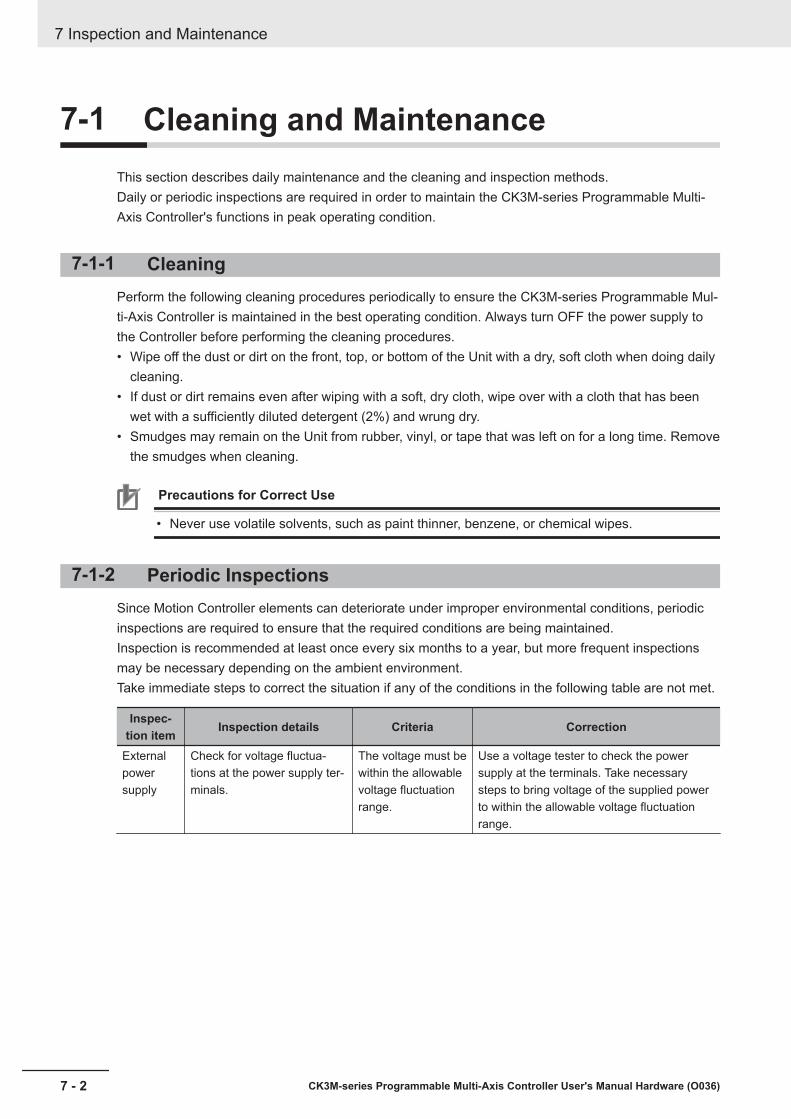
7-1 Cleaning and MaintenanceThis section describes daily maintenance and the cleaning and inspection methods.Daily or periodic inspections are required in order to maintain the CK3M-series Programmable Multi-Axis Controller's functions in peak operating condition.
7-1-1 CleaningPerform the following cleaning procedures periodically to ensure the CK3M-series Programmable Mul-ti-Axis Controller is maintained in the best operating condition. Always turn OFF the power supply tothe Controller before performing the cleaning procedures.• Wipe off the dust or dirt on the front, top, or bottom of the Unit with a dry, soft cloth when doing daily
cleaning.• If dust or dirt remains even after wiping with a soft, dry cloth, wipe over with a cloth that has been
wet with a sufficiently diluted detergent (2%) and wrung dry.• Smudges may remain on the Unit from rubber, vinyl, or tape that was left on for a long time. Remove
the smudges when cleaning.
Precautions for Correct Use
• Never use volatile solvents, such as paint thinner, benzene, or chemical wipes.
7-1-2 Periodic InspectionsSince Motion Controller elements can deteriorate under improper environmental conditions, periodicinspections are required to ensure that the required conditions are being maintained.Inspection is recommended at least once every six months to a year, but more frequent inspectionsmay be necessary depending on the ambient environment.Take immediate steps to correct the situation if any of the conditions in the following table are not met.
Inspec-tion item Inspection details Criteria Correction
Externalpowersupply
Check for voltage fluctua-tions at the power supply ter-minals.
The voltage must bewithin the allowablevoltage fluctuationrange.
Use a voltage tester to check the powersupply at the terminals. Take necessarysteps to bring voltage of the supplied powerto within the allowable voltage fluctuationrange.
7 Inspection and Maintenance
7 - 2 CK3M-series Programmable Multi-Axis Controller User's Manual Hardware (O036)
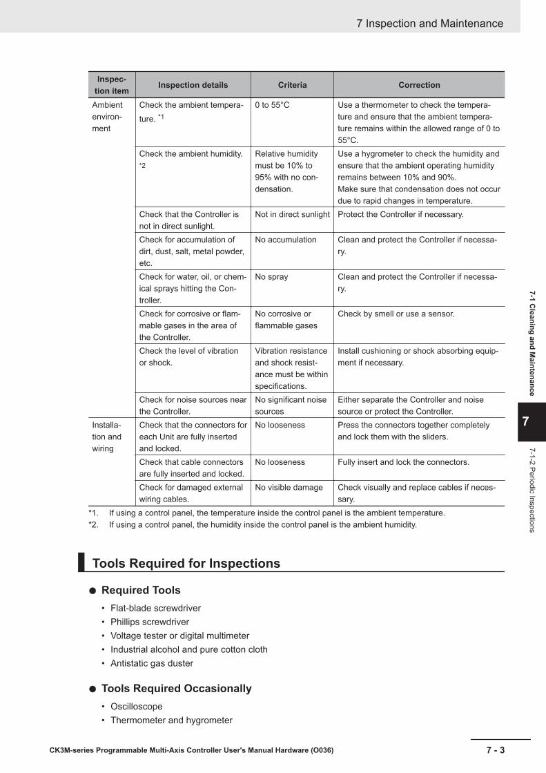
Inspec-tion item Inspection details Criteria Correction
Ambientenviron-ment
Check the ambient tempera-ture. *1
0 to 55°C Use a thermometer to check the tempera-ture and ensure that the ambient tempera-ture remains within the allowed range of 0 to55°C.
Check the ambient humidity.*2
Relative humiditymust be 10% to95% with no con-densation.
Use a hygrometer to check the humidity andensure that the ambient operating humidityremains between 10% and 90%.Make sure that condensation does not occurdue to rapid changes in temperature.
Check that the Controller isnot in direct sunlight.
Not in direct sunlight Protect the Controller if necessary.
Check for accumulation ofdirt, dust, salt, metal powder,etc.
No accumulation Clean and protect the Controller if necessa-ry.
Check for water, oil, or chem-ical sprays hitting the Con-troller.
No spray Clean and protect the Controller if necessa-ry.
Check for corrosive or flam-mable gases in the area ofthe Controller.
No corrosive orflammable gases
Check by smell or use a sensor.
Check the level of vibrationor shock.
Vibration resistanceand shock resist-ance must be withinspecifications.
Install cushioning or shock absorbing equip-ment if necessary.
Check for noise sources nearthe Controller.
No significant noisesources
Either separate the Controller and noisesource or protect the Controller.
Installa-tion andwiring
Check that the connectors foreach Unit are fully insertedand locked.
No looseness Press the connectors together completelyand lock them with the sliders.
Check that cable connectorsare fully inserted and locked.
No looseness Fully insert and lock the connectors.
Check for damaged externalwiring cables.
No visible damage Check visually and replace cables if neces-sary.
*1. If using a control panel, the temperature inside the control panel is the ambient temperature.*2. If using a control panel, the humidity inside the control panel is the ambient humidity.
Tools Required for Inspections
Required Tools• Flat-blade screwdriver• Phillips screwdriver• Voltage tester or digital multimeter• Industrial alcohol and pure cotton cloth• Antistatic gas duster
Tools Required Occasionally• Oscilloscope• Thermometer and hygrometer
7 Inspection and Maintenance
7 - 3CK3M-series Programmable Multi-Axis Controller User's Manual Hardware (O036)
7-1 Cleaning and M
aintenance
7
7-1-2 Periodic Inspections
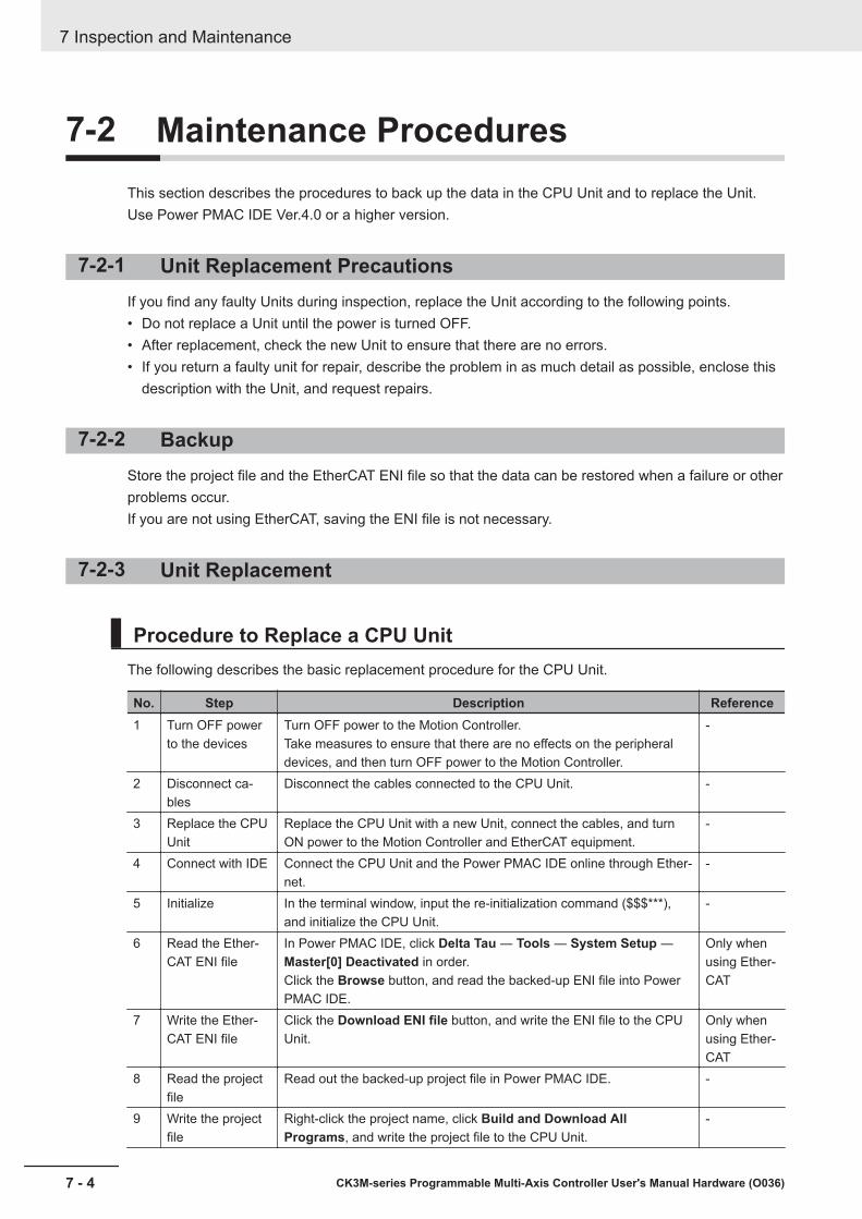
7-2 Maintenance ProceduresThis section describes the procedures to back up the data in the CPU Unit and to replace the Unit.Use Power PMAC IDE Ver.4.0 or a higher version.
7-2-1 Unit Replacement PrecautionsIf you find any faulty Units during inspection, replace the Unit according to the following points.• Do not replace a Unit until the power is turned OFF.• After replacement, check the new Unit to ensure that there are no errors.• If you return a faulty unit for repair, describe the problem in as much detail as possible, enclose this
description with the Unit, and request repairs.
7-2-2 BackupStore the project file and the EtherCAT ENI file so that the data can be restored when a failure or otherproblems occur.If you are not using EtherCAT, saving the ENI file is not necessary.
7-2-3 Unit Replacement
Procedure to Replace a CPU UnitThe following describes the basic replacement procedure for the CPU Unit.
No. Step Description Reference1 Turn OFF power
to the devicesTurn OFF power to the Motion Controller.Take measures to ensure that there are no effects on the peripheraldevices, and then turn OFF power to the Motion Controller.
-
2 Disconnect ca-bles
Disconnect the cables connected to the CPU Unit. -
3 Replace the CPUUnit
Replace the CPU Unit with a new Unit, connect the cables, and turnON power to the Motion Controller and EtherCAT equipment.
-
4 Connect with IDE Connect the CPU Unit and the Power PMAC IDE online through Ether-net.
-
5 Initialize In the terminal window, input the re-initialization command ($$$***),and initialize the CPU Unit.
-
6 Read the Ether-CAT ENI file
In Power PMAC IDE, click Delta Tau ― Tools ― System Setup ―Master[0] Deactivated in order.Click the Browse button, and read the backed-up ENI file into PowerPMAC IDE.
Only whenusing Ether-CAT
7 Write the Ether-CAT ENI file
Click the Download ENI file button, and write the ENI file to the CPUUnit.
Only whenusing Ether-CAT
8 Read the projectfile
Read out the backed-up project file in Power PMAC IDE. -
9 Write the projectfile
Right-click the project name, click Build and Download AllPrograms, and write the project file to the CPU Unit.
-
7 Inspection and Maintenance
7 - 4 CK3M-series Programmable Multi-Axis Controller User's Manual Hardware (O036)
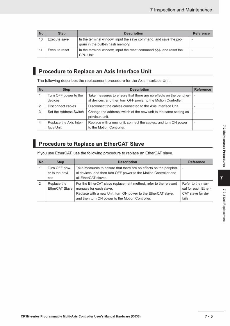
No. Step Description Reference10 Execute save In the terminal window, input the save command, and save the pro-
gram in the built-in flash memory.-
11 Execute reset In the terminal window, input the reset command $$$, and reset theCPU Unit.
-
Procedure to Replace an Axis Interface UnitThe following describes the replacement procedure for the Axis Interface Unit.
No. Step Description Reference1 Turn OFF power to the
devicesTake measures to ensure that there are no effects on the peripher-al devices, and then turn OFF power to the Motion Controller.
-
2 Disconnect cables Disconnect the cables connected to the Axis Interface Unit. -3 Set the Address Switch Change the address switch of the new unit to the same setting as
previous unit.-
4 Replace the Axis Inter-face Unit
Replace with a new unit, connect the cables, and turn ON powerto the Motion Controller.
-
Procedure to Replace an EtherCAT SlaveIf you use EtherCAT, use the following procedure to replace an EtherCAT slave.
No. Step Description Reference1 Turn OFF pow-
er to the devi-ces
Take measures to ensure that there are no effects on the peripher-al devices, and then turn OFF power to the Motion Controller andall EtherCAT slaves.
-
2 Replace theEtherCAT Slave
For the EtherCAT slave replacement method, refer to the relevantmanuals for each slave.Replace with a new Unit, turn ON power to the EtherCAT slave,and then turn ON power to the Motion Controller.
Refer to the man-ual for each Ether-CAT slave for de-tails.
7 Inspection and Maintenance
7 - 5CK3M-series Programmable Multi-Axis Controller User's Manual Hardware (O036)
7-2 Maintenance Procedures
7
7-2-3 Unit R
eplacement

7 Inspection and Maintenance
7 - 6 CK3M-series Programmable Multi-Axis Controller User's Manual Hardware (O036)
AAppendices
The appendices provide the general specifications, the Unit dimensions, and restric-tions on using the OMRON EtherCAT Coupler Unit.
A-1 General Specifications ............................................................................... A - 2A-2 Dimensions.................................................................................................. A - 3
A-2-1 CPU Unit .......................................................................................................A - 3A-2-2 Power Supply Unit ........................................................................................A - 4A-2-3 Axis Interface Unit.........................................................................................A - 4A-2-4 End Cover.....................................................................................................A - 5
A-3 Restrictions on Using the NX-series EtherCAT Coupler Unit ................. A - 6A-4 OMRON Servo Drive Connection Example............................................... A - 7
A - 1CK3M-series Programmable Multi-Axis Controller User's Manual Hardware (O036)
A

A-1 General SpecificationsThis section describes the Motion Controller specifications.
Item SpecificationEnclosure Mounted in a panelGrounding Method Ground to less than 100 Ω.
Operating Environ-ment
Ambient OperatingTemperature
0 to 55°C
Ambient Operating Hu-midity
10% to 95% (with no condensation or icing)
Atmosphere Must be free of corrosive gases.Ambient Storage Tem-perature
-25 to 70°C (with no condensation or icing)
Vibration Resistance
Conforms to IEC 60068-2-6.5 to 8.4 Hz with 3.5-mm amplitude,8.4 to 150 Hz, acceleration of 9.8 m/s2
100 min each in X, Y, and Z directions (10 sweeps of 10min each = 100 min total)
Shock ResistanceConforms to IEC 60068-2-27.147 m/s2, 3 times each in X, Y, and Z directions
Insulation Resistance 20 MΩ min. between isolated circuits (at 100 VDC)
Dielectric Strength 510 VAC between isolated circuits for 1 minute with aleakage current of 5 mA max.
Applicable Standards cULus, EU: EN 61326, RCM, KC, EAC
Appendices
A - 2 CK3M-series Programmable Multi-Axis Controller User's Manual Hardware (O036)
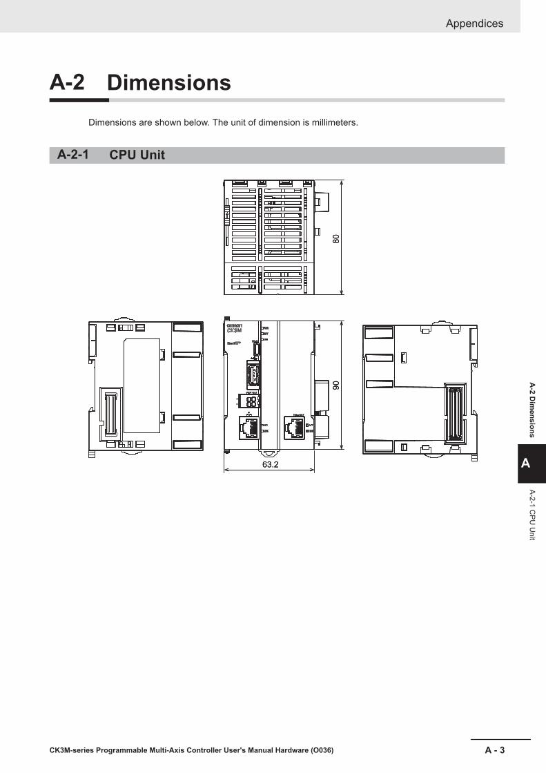
A-2 DimensionsDimensions are shown below. The unit of dimension is millimeters.
A-2-1 CPU Unit
80
90
63.2
80
90
63.2
Appendices
A - 3CK3M-series Programmable Multi-Axis Controller User's Manual Hardware (O036)
A-2 D
imensions
A
A-2-1 CPU
Unit

A-2-2 Power Supply Unit
80
90
45
A-2-3 Axis Interface Unit
80
90
130
IN0 1 2 3 4 5 6 7
8 9 10 11 12 13 14 15
0 1 2 3 4 5 6 7
8 9 10 11 12 13 14 15OUT
Appendices
A - 4 CK3M-series Programmable Multi-Axis Controller User's Manual Hardware (O036)
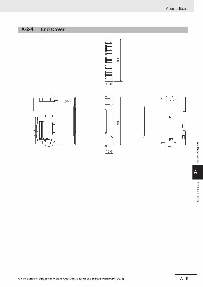
A-2-4 End Cover
80
90
15.6
15.6
Appendices
A - 5CK3M-series Programmable Multi-Axis Controller User's Manual Hardware (O036)
A-2 D
imensions
A
A-2-4 End Cover
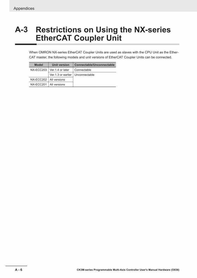
A-3 Restrictions on Using the NX-seriesEtherCAT Coupler Unit
When OMRON NX-series EtherCAT Coupler Units are used as slaves with the CPU Unit as the Ether-CAT master, the following models and unit versions of EtherCAT Coupler Units can be connected.
Model Unit version Connectable/UnconnectableNX-ECC203 Ver.1.4 or later Connectable
Ver.1.3 or earlier UnconnectableNX-ECC202 All versionsNX-ECC201 All versions
Appendices
A - 6 CK3M-series Programmable Multi-Axis Controller User's Manual Hardware (O036)
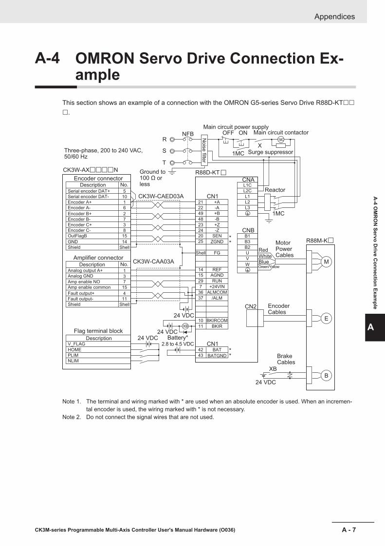
A-4 OMRON Servo Drive Connection Ex-ample
This section shows an example of a connection with the OMRON G5-series Servo Drive R88D-KT£££.
Three-phase, 200 to 240 VAC,
50/60 Hz
R88D-KT
R88M-K
CK3W-CAED03A
CK3W-CAA03A
Ground to
100 Ω or
lessN
ois
e filte
r
Main circuit power supply
Main circuit contactor
Surge suppressor
Encoder connector
Description
Serial encoder DAT+
Serial encoder DAT-
Encoder A+
Encoder A-
Encoder B+
Encoder B-
Encoder C+
Encoder C-
OutFlagB
GND
Shield
+A
-A
+B
-B
+Z
-Z
SEN
ZGND
FG
REF
AGND
RUN
+24VIN
ALMCOM
/ALM
BKIRCOM
BAT
BATGND
BKIR
CN1
CN1
CNA
CNB
Amplifier connector
Description
Analog output A+
Analog GND
Amp enable NO
Amp enable common
Fault output+
Fault output-
Shield
Flag terminal block
Description
V_FLAG
HOME
PLIM
NLIM
**
**
Reactor
Motor
Power
Cables
Encoder
Cables
Brake
Cables
Red
White
Blue
Battery*
2.8 to 4.5 VDC
R
S
T
NFB OFF ON
X
1MC
1MC
5
10
1
6
2
7
3
8
15
14
Shell
No.
21
L1C
L2C
L1
L2
L3
B1
B3
B2
U
V
W
22
49
42
43
48
23
24
20
25
Shell
14
15
29
7
36
37
10
11
1
3
7
15
4
11
Shell
No.
CN2
XB
24 VDC
24 VDC
24 VDC
24 VDC
1MC
M
E
B
XB
Green/Yellow
CK3W-AX N£££££
£
Note 1. The terminal and wiring marked with * are used when an absolute encoder is used. When an incremen-tal encoder is used, the wiring marked with * is not necessary.
Note 2. Do not connect the signal wires that are not used.
Appendices
A - 7CK3M-series Programmable Multi-Axis Controller User's Manual Hardware (O036)
A-4 O
MR
ON
Servo Drive C
onnection Example
A

Appendices
A - 8 CK3M-series Programmable Multi-Axis Controller User's Manual Hardware (O036)
IIndex
I - 1CK3M-series Programmable Multi-Axis Controller User's Manual Hardware (O036)
I

IndexA
Applicable Wires......................................... 5 - 2,5 - 15,5 - 25
B
Basic Configuration......................................................... 1 - 2Basic System Configuration............................................ 2 - 2
C
Cleaning.......................................................................... 7 - 2CPU Rack........................................................................2 - 2CPU Unit..........................................................................3 - 2Crimping Tool.............................................. 5 - 3,5 - 15,5 - 25
D
Daisy Chain......................................................... 4 - 22,4 - 24DIN Track.......................................................................4 - 11DIN Track End Plates.................................................... 4 - 11
E
Earthing Methods.......................................................... 4 - 22ECAT ACT....................................................................... 3 - 6ECAT LINK...................................................................... 3 - 6Equipotential bonding system............................. 4 - 22,4 - 23ERR................................................................................. 3 - 6EtherCAT communications connector............................. 3 - 4EtherCAT communications port operation indicators.......3 - 5EtherCAT Network Configuration.....................................2 - 3Ethernet ACT...................................................................3 - 6Ethernet communications connector............................... 3 - 5Ethernet communications port operation indicators........ 3 - 5Ethernet LINK.................................................................. 3 - 6Ethernet Network Configuration...................................... 2 - 5
F
Ferrule.........................................................5 - 2,5 - 15,5 - 25Functional Grounding.................................................... 4 - 26
G
Grounding......................................................................4 - 22
I
Initialization of CPU Unit..................................................6 - 8Installation Dimensions..................................................4 - 13Installation height...........................................................4 - 13Installation in Cabinets or Control Panels........................4 - 4
O
Operating Procedure....................................................... 1 - 5
Output Specifications.......................................................3 - 7Output Status...................................................................3 - 6
P
Performance Specifications.............................................3 - 2Power Supply Unit........................................................... 3 - 9PWR................................................................................ 3 - 5
R
RDY................................................................................. 3 - 6Recommended Power Supplies...................................... 3 - 9
S
Slider............................................................................... 3 - 4Solid Wires..................... 5 - 3,5 - 4,5 - 15,5 - 16,5 - 25,5 - 26Star earthing........................................................4 - 22,4 - 23Support Software.............................................................1 - 4
T
Twisted Wires................. 5 - 3,5 - 4,5 - 15,5 - 16,5 - 25,5 - 26
U
Unit connector................................................................. 3 - 5USB 2.0 connector.......................................................... 3 - 5USB connector for maintenance......................................3 - 5
W
Watchdog Output Terminal Block............................ 3 - 5,3 - 6Wiring Ducts.................................................................... 4 - 6
Index
I - 2 CK3M-series Programmable Multi-Axis Controller User's Manual Hardware (O036)


Authorized Distributor:
In the interest of product improvement,
specifications are subject to change without notice.
Cat. No. O036-E1-01 0718
© OMRON Corporation 2018 All Rights Reserved.
OMRON Corporation Industrial Automation Company
OMRON ELECTRONICS LLC2895 Greenspoint Parkway, Suite 200
Hoffman Estates, IL 60169 U.S.A.
Tel: (1) 847-843-7900/Fax: (1) 847-843-7787
Regional Headquarters
OMRON EUROPE B.V.Wegalaan 67-69, 2132 JD Hoofddorp
The Netherlands
Tel: (31)2356-81-300/Fax: (31)2356-81-388
Contact: www.ia.omron.com
Kyoto, JAPAN
OMRON ASIA PACIFIC PTE. LTD.No. 438A Alexandra Road # 05-05/08 (Lobby 2),
Alexandra Technopark,
Singapore 119967
Tel: (65) 6835-3011/Fax: (65) 6835-2711
OMRON (CHINA) CO., LTD.Room 2211, Bank of China Tower,
200 Yin Cheng Zhong Road,
PuDong New Area, Shanghai, 200120, China
Tel: (86) 21-5037-2222/Fax: (86) 21-5037-2200