Embed Size (px)
Citation preview

Hardware Installation Guide for the Cisco 1100 Series IntegratedServices RouterLast Modified: 2017-11-09
Americas HeadquartersCisco Systems, Inc.170 West Tasman DriveSan Jose, CA 95134-1706USAhttp://www.cisco.comTel: 408 526-4000 800 553-NETS (6387)Fax: 408 527-0883

© 2017-2017 Cisco Systems, Inc. All rights reserved.
C O N T E N T S
P r e f a c e Preface vii
Audience vii
Document Organization vii
Document Conventions viii
Related Documentation ix
Obtaining Documentation and Submitting a Service Request x
C H A P T E R 1 Overview of Cisco 1100 Series Integrated Services Routers 1
Overview 1
About Cisco 1100 Series Integrated Service Routers 1
Chassis Views 2
Labels on the Router 3
For Additional Help Locating Labels on the Router 4
Hardware Features 4
Interface Ports 4
Power-over-Ethernet (PoE) 5
LED Indicators 5
Reset Button 10
Slots and Interfaces 10
About Slots, Subslots, and Port Numbering 10
Subslot/Bay Numbering 11
Specification 11
Periodic Inspection and Cleaning 14
C H A P T E R 2 Preparing for Router Installation 15
Preparing for Router Installation 15
Safety Recommendations 15
Hardware Installation Guide for the Cisco 1100 Series Integrated Services Router iii

Safety With Electricity 15
Preventing Electrostatic Discharge Damage 16
General Site Requirements 16
Site Selection Guidelines 17
Rack Requirements 17
Router Environmental Requirements 17
Power Guidelines and Requirements 18
Network Cabling Specifications 18
Console Port Connections 18
EIA/TIA-232 18
USB Serial Console 19
Console Port Considerations 19
Preparing for Network Connections 20
Ethernet Connections 20
Required Tools and Equipment for Installation and Maintenance 20
Installation Checklist 21
Creating a Site Log 22
C H A P T E R 3 Installing and Connecting the Router 23
Installing and Connecting the Router 23
Safety Warnings 23
What You Need to Know 23
Before You Begin 24
Unpacking the Router 24
Installing the Router 24
Installing a Cisco 1100 Series ISR 24
Attaching the Chassis 25
Mounting on the Wall 25
Attaching DIN Rail Brackets 28
Mounting the Router in a Rack 30
Setting the Chassis on a Desktop 31
Chassis Grounding 31
Connecting to a Console Terminal or Modem 32
Connecting to the Serial Port with Microsoft Windows 33
Connecting to the Console Port with Mac OS X 34
Hardware Installation Guide for the Cisco 1100 Series Integrated Services Routeriv
Contents
Connecting to the Console Port with Linux 34
Installing the Cisco Microsoft Windows USB Device Driver 35
Installing the Cisco Microsoft Windows XP USB Driver 35
Installing the Cisco Microsoft Windows 2000 USB Driver 36
Installing the Cisco Microsoft Windows Vista USB Driver 36
Installing the Cisco Microsoft Windows 8/Windows 10 USB Driver 36
Uninstalling the Cisco Microsoft Windows USB Driver 37
Uninstalling the Cisco Microsoft Windows XP and 2000 USB Driver 37
Uninstalling the Cisco Microsoft Windows Vista USB Driver 38
Connecting WAN and LAN Interfaces 38
Ports and Cabling 39
Connection Procedures and Precautions 39
C H A P T E R 4 ROMMonitor Overview and Basic Procedures 41
ROMMonitor Overview and Basic Procedures 41
ROMMonitor Overview 41
Entering ROM Monitor Mode 42
Checking the Current ROMmon Version 42
Commonly Used ROMMonitor Commands 43
Displaying the Available ROM Monitor Commands 43
Examples 44
Changing the ROM Monitor Prompt 44
Displaying the Configuration Register Setting 44
Environment Variable Settings 45
Frequently Used Environmental Variables 45
Displaying Environment Variable Settings 45
Entering Environment Variable Settings 46
Saving Environment Variable Settings 46
Exiting ROM Monitor Mode 46
Configuration Example 47
Upgrading the ROMmon for a Router 47
C H A P T E R 5 Installing and Upgrading Internal Modules and FRUs 49
Installing and Upgrading Internal Modules and FRUs 49
Safety Warnings 49
Hardware Installation Guide for the Cisco 1100 Series Integrated Services Router v
Contents

Accessing Internal Modules 49
Replacing the Chassis Cover 50
Removing the Cover 50
Replacing the Cover 51
Locating Internal and External Slots for Modules 51
Installing the Internal PoE Daughter Card 52
Removing and Replacing the Internal PoE Daughter Card 53
Removing and Replacing the USB Flash Token Memory Stick 53
AC Power Supplies 54
Overview of the AC Power Supply 54
Installing and Removing SFP Modules 54
Installing SFPs 61
Removing SFP Modules 61
Hardware Installation Guide for the Cisco 1100 Series Integrated Services Routervi
Contents

Preface
• Audience, page vii
• Document Organization, page vii
• Document Conventions, page viii
• Related Documentation, page ix
• Obtaining Documentation and Submitting a Service Request, page x
AudienceThis guide is intended for Cisco equipment providers and service personnel who are technically knowledgeableand familiar with Cisco routers and Cisco IOS software and features. They would understand how to install,configure, and maintain the router, and they should be familiar with electronic circuitry and wiring practices,and have experience as an electronic or electromechanical technician. This guide identifies certain proceduresthat should be performed only by trained and qualified personnel.
Document OrganizationThis guide includes the following chapters and appendix::
DescriptionTitleChapter//Appendix
Describes the router chassis views, general hardwarefeatures, slot, port and interface information, and LEDindicators.
Overview of the Cisco1100 Series ISR
Chapter 1
Describes site requirements and the equipment neededto install the router.
Preparing for RouterInstallation
Chapter 2
Describes how to install and connect the router to LANand WAN.
Installing andConnecting the Router
Chapter 3
Hardware Installation Guide for the Cisco 1100 Series Integrated Services Router vii
DescriptionTitleChapter//Appendix
Provides an overview of ROM Monitor concepts andoperations.
ROMMonitor Overviewand Basic Procedures
Chapter 4
Describes how to install and upgrade internal modulesand field replaceable units1 on the router.
Installing andUpgradingInternal Modules andFRUs
Chapter 5
1 Field Replaceable Unit
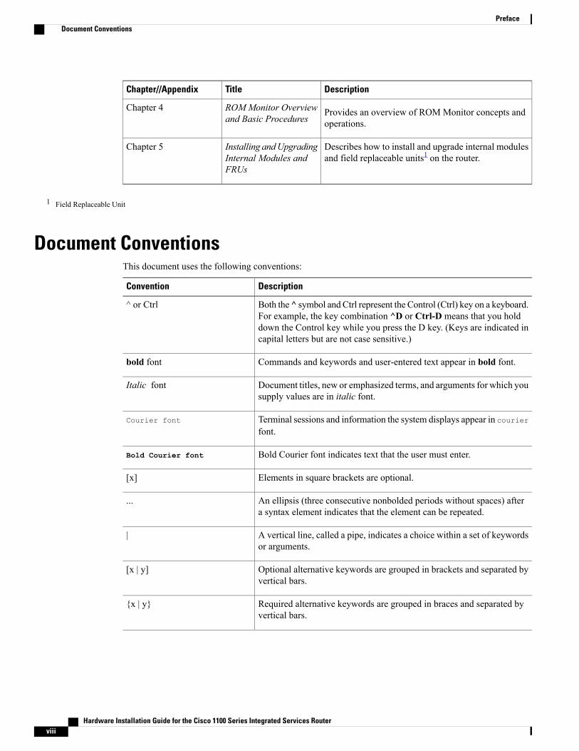
Document ConventionsThis document uses the following conventions:
DescriptionConvention
Both the ^ symbol and Ctrl represent the Control (Ctrl) key on a keyboard.For example, the key combination ^D or Ctrl-D means that you holddown the Control key while you press the D key. (Keys are indicated incapital letters but are not case sensitive.)
^ or Ctrl
Commands and keywords and user-entered text appear in bold font.bold font
Document titles, new or emphasized terms, and arguments for which yousupply values are in italic font.
Italic font
Terminal sessions and information the system displays appear in courierfont.
Courier font
Bold Courier font indicates text that the user must enter.Bold Courier font
Elements in square brackets are optional.[x]
An ellipsis (three consecutive nonbolded periods without spaces) aftera syntax element indicates that the element can be repeated.
...
A vertical line, called a pipe, indicates a choice within a set of keywordsor arguments.
|
Optional alternative keywords are grouped in brackets and separated byvertical bars.
[x | y]
Required alternative keywords are grouped in braces and separated byvertical bars.
x | y
Hardware Installation Guide for the Cisco 1100 Series Integrated Services Routerviii
PrefaceDocument Conventions
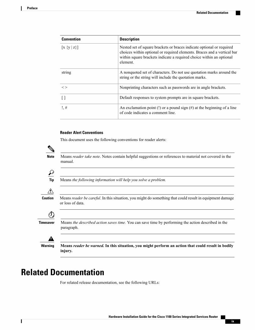
DescriptionConvention
Nested set of square brackets or braces indicate optional or requiredchoices within optional or required elements. Braces and a vertical barwithin square brackets indicate a required choice within an optionalelement.
[x y | z]
A nonquoted set of characters. Do not use quotation marks around thestring or the string will include the quotation marks.
string
Nonprinting characters such as passwords are in angle brackets.< >
Default responses to system prompts are in square brackets.[ ]
An exclamation point (!) or a pound sign (#) at the beginning of a lineof code indicates a comment line.
!, #
Reader Alert Conventions
This document uses the following conventions for reader alerts:
Means reader take note. Notes contain helpful suggestions or references to material not covered in themanual.
Note
Means the following information will help you solve a problem.Tip
Means reader be careful. In this situation, you might do something that could result in equipment damageor loss of data.
Caution
Means the described action saves time. You can save time by performing the action described in theparagraph.
Timesaver
Means reader be warned. In this situation, you might perform an action that could result in bodilyinjury.
Warning
Related DocumentationFor related release documentation, see the following URLs:
Hardware Installation Guide for the Cisco 1100 Series Integrated Services Router ix
PrefaceRelated Documentation
Cisco 1100 Series ISR Release Notes: https://www.cisco.com/c/en/us/td/docs/routers/access/1100/release/16-6-2/isr1k-rel-notes-xe-16-6.html
Cisco 1100 Series ISR Configuration Guide - https://www.cisco.com/c/en/us/td/docs/routers/access/1100/software/configuration/guide/cisco_1100_series_swcfg.html
Obtaining Documentation and Submitting a Service RequestFor information on obtaining documentation, submitting a service request, and gathering additional information,see What’s New in Cisco Product Documentation at: http://www.cisco.com/en/US/docs/general/whatsnew/whatsnew.html.
Subscribe to What’s New in Cisco Product Documentation, which lists all new and revised Cisco technicaldocumentation, as an RSS feed and deliver content directly to your desktop using a reader application. TheRSS feeds are a free service.
Hardware Installation Guide for the Cisco 1100 Series Integrated Services Routerx
PrefaceObtaining Documentation and Submitting a Service Request

C H A P T E R 1Overview of Cisco 1100 Series IntegratedServices Routers
• Overview , page 1
OverviewCisco 1100 Series Integrated Services Routers (ISRs) with Cisco IOS XE Software combine Internet access,comprehensive security, and wireless services (LTE Advanced 3.0, Wireless WAN and Wireless LAN), arehigh-performance devices that are easy to deploy andmanage. They are well suited for deployment as customerpremises equipment (CPE) in enterprise branch offices, and in service provider managed-service environments.
These ISRs are the industry leader in bringing enterprise-grade wired-line-like functionality such as qualityof service (QoS) for cellular, Multi-VRF, advanced VPN, and unified communications solutions over LTE.
The 1100 Series also provides the ability to extend Cisco product-based networks to remote offices with arelatively low incremental investment, as well as to enable managed services offerings based on end-to-endCisco system architecture.
About Cisco 1100 Series Integrated Service RoutersThe Cisco 1100 Series ISRs are fixed branch routers based on the Cisco IOS XE Everest 16.6.2 operatingsystem, with a multi-core Data Plane.
The two types of platforms supported on Cisco 1100 Series ISRs are 8-port and 4-port platforms.
8-port platforms are high-performance, managed service provider and enterprise platforms having:
• 8-port integrated front panel switch ports
• Optional PoE on LAN daughter card with support up to 4PoE/2PoE+ports
• Optional WLAN support - 802.11ac WAVE 2
• 4G LTE-Advanced support with carrier aggregation
4-port platforms are midrange performance, managed service provider platforms and enterprise platformshaving:
Hardware Installation Guide for the Cisco 1100 Series Integrated Services Router 1

• 4-port integrated front panel switch ports
• VDSL2 and ADSL2/2+ support
• Optional POE on LAN daughter card supporting 2PoE/1PoE+ ports
• Optional WLAN support - 802.11ac WAVE 2
• 4G LTE-Advanced support with carrier aggregation
Chassis ViewsThis section contains views of the front and back panels of the Cisco 1100 Series ISR, showing locations ofthe power and signal interfaces, interface slots, status indicators, and chassis identification labels.
Bezel View
Figure 1: Cisco 1100 Series ISR - Bezel View
VPN2Status1
GPS4WiFi3
LTE Data/SIM6LTE Signal Intensity5
Illuminated Cisco Logo7
Hardware Installation Guide for the Cisco 1100 Series Integrated Services Router2
Overview of Cisco 1100 Series Integrated Services RoutersChassis Views
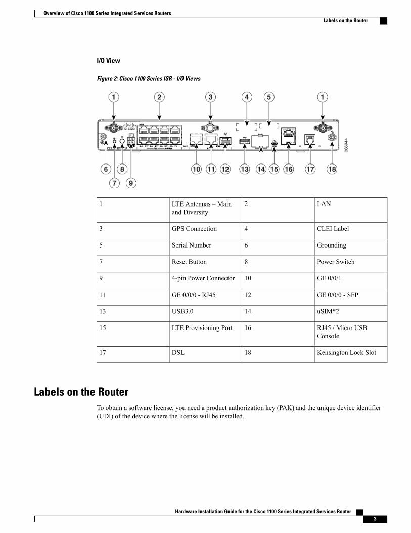
I/O View
Figure 2: Cisco 1100 Series ISR - I/O Views
LAN2LTE Antennas –Mainand Diversity
1
CLEI Label4GPS Connection3
Grounding6Serial Number5
Power Switch8Reset Button7
GE 0/0/1104-pin Power Connector9
GE 0/0/0 - SFP12GE 0/0/0 - RJ4511
uSIM*214USB3.013
RJ45 / Micro USBConsole
16LTE Provisioning Port15
Kensington Lock Slot18DSL17
Labels on the RouterTo obtain a software license, you need a product authorization key (PAK) and the unique device identifier(UDI) of the device where the license will be installed.
Hardware Installation Guide for the Cisco 1100 Series Integrated Services Router 3
Overview of Cisco 1100 Series Integrated Services RoutersLabels on the Router

Figure shows the location of the labels on the Cisco 1100 Series ISRs:
Figure 3: Labels on the Routers
DescriptionNameSl. No
Common Language EquipmentIdentifier (CLEI) number
CLEI Number1
Serial Number2
Product Identification NumberPID Family Name3
For Additional Help Locating Labels on the RouterUse the Cisco Product Identification (CPI) tool to find labels on the router. The tool provides detailedillustrations and descriptions of where the labels are located on Cisco products. It includes the followingfeatures:
• A search option that allows browsing for models by using a tree-structured product hierarchy
• A search field on the final results page that makes it easier to look up multiple products
• End-of-sale products clearly identified in results lists
The tool streamlines the process of locating serial number labels and identifying products. Serial numberinformation expedites the entitlement process and is important for access to support services.
Hardware FeaturesThis section describes the hardware features in the routers.
Interface PortsThe Cisco ISR C1100-8P series comes with 8-Gigabit Ethernet LAN ports, and twoWAN ports, with optionsfor one LTE modem and one WLAN interface.
Hardware Installation Guide for the Cisco 1100 Series Integrated Services Router4
Overview of Cisco 1100 Series Integrated Services RoutersFor Additional Help Locating Labels on the Router

The Cisco ISR C1100-4P series comes with 4-Gigabit Ethernet LAN ports, and twoWAN ports, with optionsfor one LTE modem and one WLAN interface.
Power-over-Ethernet (PoE)The C1100-8P series has 8 Ethernet LAN ports. Four of the Ethernet LAN ports are PoE-capable, LAN ports0-3. A total of 80W of PoE power is available across the four PoE-capable ports on the C1100-8P series.
The C1100-4P series has 4 Ethernet LAN ports. Two of the Ethernet LAN ports are PoE-capable, LAN ports0-1. A total of 60W of PoE power is available across the two PoE-capable ports on the C1100-4P series.
Each individual PoE-capable Ethernet LAN port is capable of PoE 802.3af or PoE+ 802.3at functionality.The total number of PoE and/or PoE+ devices that can be enabled on the PoE ports at any one time is a functionof the PoE power available from the external power supply. Software will allocate PoE power based on thePoE power requested by the device on each port; and manage the total available power so as not to allocatemore power than what is available.
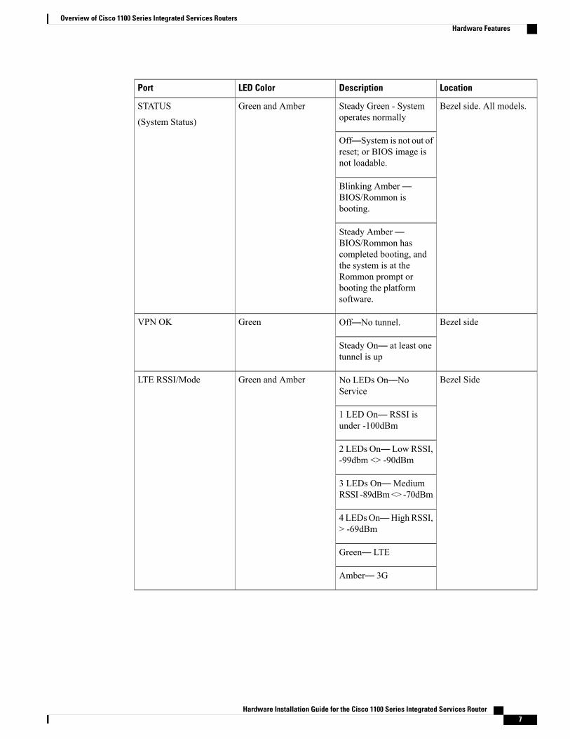
LED IndicatorsThe following figures and table summarizes the LED indicators that are located in the router bezel or chassis,but not on the interface cards and modules.
Figure 4: LED Indicators - Bezel Side
VPN2Status1
GPS4WLAN3
LTE DATA/SIM6LTE RSSI/Mode5
Cisco Logo7
Hardware Installation Guide for the Cisco 1100 Series Integrated Services Router 5
Overview of Cisco 1100 Series Integrated Services RoutersHardware Features

Figure 5: LED Indicators - I/O Side
PoE LED2GE WAN Ports: 0-7(0,2,4,6 at the top and1,3,5,7 at the bottom)
1
GE0 LED4GE1 LED3
RJ-45 Console LED6USB LED5
MicroUSBConsole LED8USB Console7
DSL10CD LED9
DATA LED11
Table 1: LED Indicators - Description
LocationDescriptionLED ColorPort
Bezel sideBezel illuminated Ciscologo. Indicates routerpower is good.
BlueCisco Logo
Hardware Installation Guide for the Cisco 1100 Series Integrated Services Router6
Overview of Cisco 1100 Series Integrated Services RoutersHardware Features
LocationDescriptionLED ColorPort
Bezel side. All models.Steady Green - Systemoperates normally
Green and AmberSTATUS
(System Status)
Off—System is not out ofreset; or BIOS image isnot loadable.
Blinking Amber—BIOS/Rommon isbooting.
Steady Amber—BIOS/Rommon hascompleted booting, andthe system is at theRommon prompt orbooting the platformsoftware.
Bezel sideOff—No tunnel.GreenVPN OK
Steady On— at least onetunnel is up
Bezel SideNo LEDs On—NoService
Green and AmberLTE RSSI/Mode
1 LED On— RSSI isunder -100dBm
2 LEDs On— Low RSSI,-99dbm <> -90dBm
3 LEDs On—MediumRSSI -89dBm<> -70dBm
4LEDsOn—High RSSI,> -69dBm
Green— LTE
Amber— 3G
Hardware Installation Guide for the Cisco 1100 Series Integrated Services Router 7
Overview of Cisco 1100 Series Integrated Services RoutersHardware Features

LocationDescriptionLED ColorPort
Bezel SideAmber— Assisted GPS(Reserved for Future Use)
Green and AmberGPS
Green— StandaloneGPS
Off— GPS notconfigured
On— GPS configured
Blink— GPS Acquiring
Bezel SideSingle LTE Modem (onemodem with SIMswitch-over capability)
Green and AmberLTE DATA/SIM
Off—Modem not up ormodem up and no SIM
Amber Steady On—Modem up, SIM installedbut not active.
Green Steady On—Modem up, SIM installedand active.
Green Blink— LTE dataactivity.
Bezel sideGreen— Normaloperating condition withat least one wireless clientassociation.
Green, Red, and AmberWLAN
Red—Ethernet link is notoperational or Ethernetfailure.
Amber—Softwareupgrade is in progress.
I/O sideOff— No linkGreenEthernet SwitchGELANPorts, Non-PoE
Steady On— link
Blink— TXD/RXD data
Hardware Installation Guide for the Cisco 1100 Series Integrated Services Router8
Overview of Cisco 1100 Series Integrated Services RoutersHardware Features
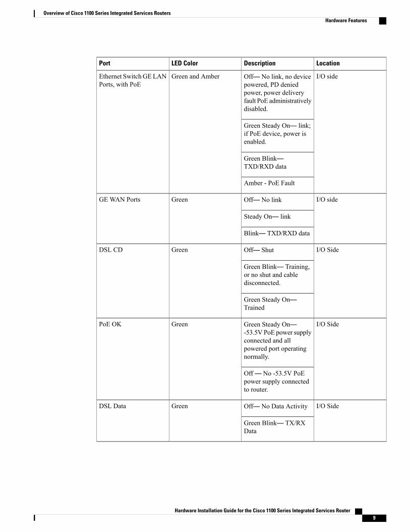
LocationDescriptionLED ColorPort
I/O sideOff— No link, no devicepowered, PD deniedpower, power deliveryfault PoE administrativelydisabled.
Green and AmberEthernet SwitchGELANPorts, with PoE
Green Steady On— link;if PoE device, power isenabled.
Green Blink—TXD/RXD data
Amber - PoE Fault
I/O sideOff— No linkGreenGE WAN Ports
Steady On— link
Blink— TXD/RXD data
I/O SideOff— ShutGreenDSL CD
Green Blink— Training,or no shut and cabledisconnected.
Green Steady On—Trained
I/O SideGreen Steady On—-53.5V PoE power supplyconnected and allpowered port operatingnormally.
GreenPoE OK
Off— No -53.5V PoEpower supply connectedto router.
I/O SideOff— No Data ActivityGreenDSL Data
Green Blink— TX/RXData
Hardware Installation Guide for the Cisco 1100 Series Integrated Services Router 9
Overview of Cisco 1100 Series Integrated Services RoutersHardware Features

LocationDescriptionLED ColorPort
I/O sideGreen On— Consoleenabled.
Green and AmberConsole/AUX
Amber On— AUXenabled.
I/O sideOff— No USB devicediscovered.
GreenUSB Console
On— USB devicediscovered.
I/O SideOff: No USB devicediscovered.
GreenUSB
On: USB devicediscovered.
Reset ButtonThe actuation of the Reset button is only recognized during Rommon boot, that is, as the router comes to theRommon prompt.
The Reset button does not require much force to be actuated. The Reset button should be actuated only witha small implement such as the tip of a pen or a paper clip. When the Reset button is pressed at startup, thesystem LED will turn green.
For more information, see the "Reset Overview" section of the Cisco 1100 Series Software ConfigurationGuide.
Slots and Interfaces
About Slots, Subslots, and Port NumberingCisco 1100 Series ISRs do not support physical and removable modules. It has only one slot, that is, slot 0.Slot 0 is the motherboard and not removable. It is reserved for integrated ports. The front panel GE ports (ornative interface ports) always reside in slot 0 and bay 0. The ports are called Gigabitethernet 0/0/0 andGigabitethernet 0/0/1.
Each interface type has its own 'bay', and port is a unique port of an interface type.
In most cases, the router designates its interfaces using a 3-tuple notation that lists the slot, bay, and port. The3-tuple value is zero based. An example of a 3-tuple is 0/1/2. This refers to slot 0, the second bay in slot 0(the first bay is 0 so the second bay is 1), and the third port in bay 1. See this section for more examples.
Hardware Installation Guide for the Cisco 1100 Series Integrated Services Router10
Overview of Cisco 1100 Series Integrated Services RoutersSlots and Interfaces

Table 2: Slot, Bay, and Port Numbering
PortBaySlot3- Tuple Example
3rd2nd00/1/2
2nd1st00/0/1
Subslot/Bay NumberingAll interfaces are integrated interfaces. There is only one Bay, and the interface 'Type' is defined by a slotnumber. In this example there is only one slot, 0, and each interface is a bay:
Bay 0 Ethernet WANBay 1 Ethernet LAN (Switch)Bay 2 LTEBay 3 DSLBay 4 WiFi
Chassis type: C1117-4PLTEEAWE
Slot Type State Insert time (ago)--------- ------------------- --------------------- -----------------0 C1117-4PLTEEAWE ok 00:05:580/0 C1117-1x1GE ok 00:03:030/1 C1117-ES-4 ok 00:03:010/2 C1117-LTE ok 00:02:520/3 C1117-VADSL-A ok 00:01:560/4 ISR-AP1100AC-E ok 00:03:13
SpecificationThe following table provide Cisco 1100 ISR specification:
Table 3: Cisco 1100 Series ISR Specification
SpecificationDescription
Physical Properties
Non-LTE models:
H x W X D = 1.75 x 12.7 x 9.03 in. (42 x 323 x230mm) (includes rubber feet)
Dimensions (H x W x D)
LTE models:
H x W X D = 1.75 x 12.7 x 9.6 in. (44 x 323 x 244mm) (includes rubber feet)
5.5 Lbs. (2.5 kg) maximumWeight with AC PS (w/o modules)
AC Input Power
Hardware Installation Guide for the Cisco 1100 Series Integrated Services Router 11
Overview of Cisco 1100 Series Integrated Services RoutersSpecification

SpecificationDescription
Universal 100 to 240 VACInput voltage
50-60 HzFrequency
PoE not enabled: 0.82A maximum
PoE enabled: 1.55A Maximum
Input current
90 A peak and less than 8 Arms per half cycleSurge current
Ports
One RJ-45: Separate console portMicro USB Port
USB 3.0 Type A host port
USB devices supported:
• USB flash memory
USB port
One USB 5-pin micro Type B: Console managementconnectivity
Console port
Two GE ports allocated among RJ45 and SFP as:
One combo port with 10/100/1000RJ-45 Ethernetport or SFP Ethernet port (labeled GE0/0/0)
One dedicated 10/100/1000RJ-45 Ethernet port(labeled GE0/0/1)
10/100/1000 Gigabit Ethernet
32 (encrypted and non-encrypted VLANs)Wireless VLANs
2x2 .11ac Wave 2Wireless specifications
4GBDefault and maximum DRAM
4GBDefault and maximum flash
4 ports for -8P PIDs, 2 ports for -4P PIDs
802.3af-compliant PoE or 802.3at-compliant PoE+
Inline PoE
Not Applicable - Fanless designAcoustic for Cisco 1100 Series ISRs
Hardware Installation Guide for the Cisco 1100 Series Integrated Services Router12
Overview of Cisco 1100 Series Integrated Services RoutersSpecification

SpecificationDescription
• Emission
• 47 CFR Part 15
• CISPR 32 Edition 2
EN 300 386 V1.6.1
EN 55032:2012/ AC:2013
EN 55032:2015
EN61000-3-2 2014
EN61000-3-3: 2013
ICES-003 ISSUE 6:2016
KN 32: 2015
V-2/2015.04
V-3/2015.04
TCVN 7189: 2009
CNS13438: 2006
IEC 60950-1
EN 60950-1
UL 60950-1
CSA C22.2 No. 60950-1
• Immunity
CISPR24: 2010 + A1: 2015
EN 300 386 V1.6.1
EN55024: 2010 + A1: 2015
KN35: 2015
TCVN 7317: 2003
Approvals and compliance
Table 4: Environmental Specification
SpecificationDescription
Environmental
5 to 85% relative humidityOperating humidity
Hardware Installation Guide for the Cisco 1100 Series Integrated Services Router 13
Overview of Cisco 1100 Series Integrated Services RoutersSpecification

SpecificationDescription
32 to 104°F (0 to 40°C) Sea Level;
32 to 77°F (0°C to 25°C) at 10,000 ft
1.5°C derating per 1000 ft
Operating temperature
0-6560 ft (0-2000 m)Altitude in China
0-10,000 ft (0-3050 m)Altitude in all other countries
Transportation and Storage
-40 to 158°F (-40 to 70°C)Nonoperating temperature
5 to 95% relative humidity (noncondensing)Nonoperating humidity
0 to 15,000 ft (0 to 4570m)Nonoperating altitude
Periodic Inspection and CleaningPeriodic inspection and cleaning of the external surface of the router is recommended to minimize the negativeimpact of environmental dust or debris. The frequency of inspection and cleaning is dependent upon theseverity of the environmental conditions, but a minimum of every six months is recommended. Cleaninginvolves vacuuming of router air intake and exhaust vents.
Sites with ambient temperatures consistently above 25°C or 77°F and with potentially high levels of dustor debris might require periodic preventative maintenance cleaning.
Note
Hardware Installation Guide for the Cisco 1100 Series Integrated Services Router14
Overview of Cisco 1100 Series Integrated Services RoutersPeriodic Inspection and Cleaning
C H A P T E R 2Preparing for Router Installation
• Preparing for Router Installation, page 15
Preparing for Router InstallationThis document provides pre-installation information, such as recommendations and requirements that shouldbe before installing your router. See the following sections to prepare for installation:
Safety Recommendations
This warning symbol means danger. You are in a situation that could cause bodily injury. Before youwork on any equipment, be aware of the hazards involved with electrical circuitry and be familiar withstandard practices for preventing accidents. Use the statement number provided at the end of each warningto locate its translation in the translated safety warnings that accompanied this device
Warning
SAVE THESE INSTRUCTIONS Statement 1071.Note
Ultimate disposal of this product should be handled according to all national laws and regulations. Statement1040.
Warning
Safety With Electricity
Do not work on the system or connect or disconnect cables during periods of lightning activity. Statement1001
Warning
Hardware Installation Guide for the Cisco 1100 Series Integrated Services Router 15

Installation of the equipment must comply with local and national electrical codes. Statement 1074Warning
Only trained and qualified personnel should be allowed to install or replace this equipment Statement1030
Warning
There is the danger of explosion if the battery is replaced incorrectly. Replace the battery only with thesame or equivalent type recommended by the manufacturer. Dispose of used batteries according to themanufacturer’s instructions. Statement 1015
Warning
Preventing Electrostatic Discharge DamageElectrostatic discharge (ESD) can damage equipment and impair electrical circuitry. It can occur if electronicprinted circuit cards are improperly handled and can cause complete or intermittent failures. Always followESD prevention procedures when removing and replacing modules:
• Ensure that the router chassis is electrically connected to ground.
•Wear an ESD-preventive wrist strap, ensuring that it makes good skin contact. Connect the clip to anunpainted surface of the chassis frame to channel unwanted ESD voltages safely to ground. To guardagainst ESD damage and shocks, the wrist strap and cord must operate effectively.
• If no wrist strap is available, ground yourself by touching a metal part of the chassis.
For the safety of your equipment, periodically check the resistance value of the anti-static strap. It shouldbe between 1 and 10 megohms (Mohm).
Caution
General Site RequirementsThis section describes the requirements your site must meet for safe installation and operation of your router.Ensure that the site is properly prepared before beginning installation. If you are experiencing shutdowns orunusually high errors with your existing equipment, this section can also help you isolate the cause of failuresand prevent future problems.
This product relies on the building’s installation for short-circuit (overcurrent) protection. Ensure that theprotective device is rated not greater than: 20A. Statement 1005
Warning
To prevent the system from overheating, do not operate it in an area that exceeds the maximumrecommended ambient temperature of: 40 degrees C. Statement 1047
Warning
Hardware Installation Guide for the Cisco 1100 Series Integrated Services Router16
Preparing for Router InstallationGeneral Site Requirements

Site Selection GuidelinesThe Cisco 1100 Series ISRs require specific environmental operating conditions. Temperature, humidity,altitude, and vibration can affect the performance and reliability of the router. The following sections providespecific information to help you plan for the proper operating environment.
The Cisco 1100 Series ISRs are designed to meet the industry EMC, safety, and environmental standardsdescribed in the Regulatory Compliance and Safety Information for the Cisco 1100 Series ISRs document.
Rack RequirementsCisco 1100 Series ISRs require brackets for use with a 19-inch rack.
The following information can help you plan your equipment rack configuration:
• Allow clearance around the rack for maintenance.
• Allow at least one rack unit of vertical space between routers; more clearance is required when stackingmultiple Cisco 1100 Series ISRs. Provide adequate heat removal mechanism to keep the surroundingair temperature well within the specified operating temperature condition.
More spacing may be required depending on the installation environment.Note
• Enclosed racks must have adequate ventilation. Ensure that the rack is not congested, because eachrouter generates heat. An enclosed rack should have louvered sides and a fan to provide cooling air.Heat generated by equipment near the bottom of the rack can be drawn upward into the intake ports ofthe equipment above it.
•Whenmounting a chassis in an open rack, ensure that the rack frame does not block the intake or exhaustports. If the chassis is installed on slides, check the position of the chassis when it is seated in the rack.
Router Environmental RequirementsCisco 1100 Series ISRs can be placed on a desktop, installed in a rack, or mounted on a wall. The location ofyour router and the layout of your equipment rack or wiring room are extremely important considerations forproper operation. Equipment placed too close together, inadequate ventilation, and inaccessible panels cancause malfunctions and shutdowns, and can make maintenance difficult. Plan for access to both front and rearpanels of the router.
When planning your site layout and equipment locations, refer to the General Site Requirements , section. Ifyou are currently experiencing shutdowns or an unusually high number of errors with your existing equipment,these precautions and recommendationsmay help you isolate the cause of failure and prevent future problems.
• Ensure that the room where your router operates has adequate air circulation. Electrical equipmentgenerates heat. Without adequate air circulation, ambient air temperature may not cool equipment toacceptable operating temperatures.
• Always follow ESD-prevention procedures described in the Preventing Electrostatic Discharge Damageto avoid damage to equipment. Damage from static discharge can cause immediate or intermittentequipment failure.
Hardware Installation Guide for the Cisco 1100 Series Integrated Services Router 17
Preparing for Router InstallationRack Requirements

• Baffles can help to isolate exhaust air from intake air, which also helps to draw cooling air through thechassis. The best placement of the baffles depends on the airflow patterns in the rack, which can befound by experimenting with different configurations.
•When equipment installed in a rack (particularly in an enclosed rack) fails, try operating the equipmentby itself, if possible. Power off other equipment in the rack (and in adjacent racks) to allow the routerunder test a maximum of cooling air and clean power.
Power Guidelines and RequirementsCheck the power at your site to ensure that you are receiving “clean” power (free of spikes and noise). Installa power conditioner if necessary.
Power Guidelines and Requirements lists power requirements for the Cisco 1100 Series ISRs.
Table 5: Power Requirements for Cisco 1100 Series ISRs
Output RatedInput RatedPower Source
12 VDC, 5.5A100-240V, 0.82A - 0.35A66W AC Power Adapter
(341-100346-01)
12VDC, 3.5A; -53.5Vdc, 1.55A100-240 VAC, 1.55A – 0.65A,50-60 Hz
125W AC Power Adapter
(341-0502-01)
12VDC, 4.7A; -53.5VDC, 1.2A100-240VAC, 1.43A - 0.60A,50-60 Hz
115W AC Power Adapter
(341-100765-01)
Network Cabling SpecificationsThe following sections describe the cables needed to install your Cisco 1100 Series ISR in the followingsections:
Console Port ConnectionsThe router has both EIA/TIA-232 asynchronous (RJ-45) and USB 5-pin micro Type B, 2.0 compliant serialconsole ports. The console ports do not have any hardware flow control. Shielded USB cables with properlyterminated shields are recommended.
EIA/TIA-232
Depending on the cable and the adapter used, this port appears as a DTE or DCE device at the end of thecable. Only one port can be used at the same time.
The default parameters for the console port are 9600 baud, 8 data bits, 1 stop bit, and no parity. The consoleport does not support hardware flow control. For detailed information about installing a console terminal, seethe Connecting to a Console Terminal or Modem section.
Hardware Installation Guide for the Cisco 1100 Series Integrated Services Router18
Preparing for Router InstallationPower Guidelines and Requirements
For cable and port pinouts, see the Cisco Modular Access Router Cable Specifications document located onCisco.com.
USB Serial Console
The USB serial console port connects directly to the USB connector of a PC using a USB Type A to 5-pinmicro USB Type-B cable. The USB Console supports full speed (12Mb/s) operation. The console port doesnot support hardware flow control.
Always use shielded USB cables with a properly terminated shield.Note
The default parameters for the console port are 9600 baud, 8 data bits, no parity, and 1 stop bit. For detailedinformation about installing a console terminal, see the Connecting to a Console Terminal or Modem sectionon page 3-19.
For operation with aMicrosoftWindows OS version older thanWindows 7, the CiscoWindows USBConsoleDriver must be installed on any PC connected to the console port. If the driver is not installed, prompts guideyou through a simple installation process.
The Cisco Windows USB Console Driver allows plugging and unplugging the USB cable from the consoleport without affecting Windows HyperTerminal operations. No special drivers are needed for Mac OS X orLinux.
Only one console port can be active at a time. When a cable is plugged into the USB console port, the RJ-45port becomes inactive. Conversely, when the USB cable is removed from the USB port, the RJ-45 port becomesactive.
Baud rates for the USB console port are 1200, 2400, 4800, 9600, 19200, 38400, 57600, and 115200 bps.
4- pin micro USB Type-B connectors are easily confused with 5-pin micro USB Type-B connectors. Onlythe 5-pin micro USB Type-B is supported.
Note
USB Console OS Compatibility
•Windows 10, Windows 8, Windows 7, Windows 2000, Window XP 32 bit, Windows Vista 32 bit
• Mac OS X version 10.5.4
• Redhat / Fedora Core 10 with kernel 2.6.27.5-117
• Ubuntu 8.10 with kernel 2.6.27-11
• Debian 5.0 with kernel 2.6
• Suse 11.1 with kernel 2.6.27.7-9
Console Port ConsiderationsThe router includes an asynchronous serial console port. The console ports provide access to the router usinga console terminal connected to the console port. This section discusses important cabling information toconsider before connecting the router to a console terminal or modem.
Hardware Installation Guide for the Cisco 1100 Series Integrated Services Router 19
Preparing for Router InstallationNetwork Cabling Specifications

Console terminals send data at speeds slower than modems do; therefore, the console port is ideally suitedfor use with console terminals.
Preparing for Network ConnectionsWhen setting up your router, consider distance limitations and potential electromagnetic interference (EMI)as defined by the applicable local and international regulations.
Network connection considerations are provided for:
See the following online document for more information about network connections and interfaces:
• Cisco Modular Access Router Cable Specifications
Ethernet Connections
The IEEE has established Ethernet as standard IEEE 802.3. The routers support the following Ethernetimplementations:
• 1000BASE-T—1000 Mb/s full-duplex transmission over a Category 5 or better unshielded twisted-pair(UTP) cable. Supports the Ethernet maximum length of 328 feet (100 meters).
• 100BASE-T—100 Mb/s full-duplex transmission over a Category 5 or better unshielded twisted-pair(UTP) cable. Supports the Ethernet maximum length of 328 feet (100 meters).
• 10BASE-T—10Mb/s full-duplex transmission over a Category 5 or better unshielded twisted-pair (UTP)cable. Supports the Ethernet maximum length of 328 feet (100 meters).
See the Cisco Modular Access Router Cable Specifications document at Cisco.com for information aboutEthernet cables, connectors, and pinouts.
Required Tools and Equipment for Installation and MaintenanceYou need the following tools and equipment to install and upgrade the router and its components:
• ESD-preventive cord and wrist strap
• Number 2 Phillips screwdriver
• Phillips screwdrivers: small, 3/16-in. (4 to 5 mm) and medium, 1/4-in. (6 to 7 mm)
To install or remove modules
To remove the cover, if you are upgrading memory or other components
• Screws that fit your rack
•Wire crimper
•Wire for connecting the chassis to an earth ground:
AWG 14 (2 mm 2 ) or larger wire for NEC-compliant chassis grounding
• For NEC-compliant grounding, an appropriate user-supplied ring terminal, with an inner diameter of1/4 in. (5 to 7 mm)
Hardware Installation Guide for the Cisco 1100 Series Integrated Services Router20
Preparing for Router InstallationRequired Tools and Equipment for Installation and Maintenance

Installation ChecklistThe sample installation checklist lists items and procedures for installing a new router. Make a copy of thischecklist and mark the entries when completed. Include a copy of the checklist for each router in your sitelog (described in the next section, Creating a Site Log).
Table 6: Checklist
DateVerified ByTask
Installation checklist copied
Background information placed inSite Log
Site power voltages verified
Installation site power checkcompleted
Required tools available
Additional equipment available
Router received
Router quick start guide received
Regulatory Compliance and SafetyInformation for the Cisco 1100Series ISRs document received
Product registration card received
Cisco.com contact informationlabel received
Chassis components verified
Initial electrical connectionsestablished
ASCII terminal (for localconfiguration) or modem (forremote configuration) available
Signal distance limits verified
Startup sequence steps completed
Hardware Installation Guide for the Cisco 1100 Series Integrated Services Router 21
Preparing for Router InstallationInstallation Checklist

DateVerified ByTask
Initial operation verified
Software image verified
Creating a Site LogThe Site Log provides a record of all actions related to the router. Keep it in an accessible place near thechassis where anyone who performs tasks has access to it. Use the installation checklist to verify steps in theinstallation and maintenance of the router. Site Log entries might include the following information:
• Installation progress—Make a copy of the installation checklist and insert it into the site log. Makeentries as each procedure is completed.
• Upgrade and maintenance procedures—Use the site log as a record of ongoing router maintenance andexpansion history. A site log might include the following events:
Removal or replacement of PoE daughter card
Configuration changes
Maintenance schedules and requirements
Maintenance procedures performed
Intermittent problems
Comments and notes
Inspect all items for shipping damage. If anything appears to be damaged or if you encounter problemsinstalling or configuring your router, contact customer service. Warranty, service, and support information isin the quick start guide that shipped with your router, or in the Preface of this guide. See the ObtainingDocumentation and Submitting a Service Request section.
Hardware Installation Guide for the Cisco 1100 Series Integrated Services Router22
Preparing for Router InstallationCreating a Site Log

C H A P T E R 3Installing and Connecting the Router
• Installing and Connecting the Router, page 23
Installing and Connecting the RouterThis document describes how to install and connect the Cisco 1100 Series Integrated Services Routers (ISRs)to LAN and WAN networks. The following sections provide technical details.
Safety Warnings
Read the installation instructions before using, installing or connecting the system to the power source.Statement 1004
Warning
What You Need to Know
CLI Console Access
Use the USB or RJ-45 console port on the router to access the Cisco Internet Operating System (IOS-XE)command line interface (CLI) on the router and perform configuration tasks. A terminal emulation programis required to establish communication between the router and a PC. See the Connecting to a Console Terminalor Modem for instructions.
A Microsoft Windows USB driver must be installed before you establish physical connectivity betweenthe router and the PC.
Note
Slot and Port Numbers
The routers have built in ports and slots. See the About Slots and Interfaces section for slot and port numbering.
Hardware Installation Guide for the Cisco 1100 Series Integrated Services Router 23
Software Licenses
To use all the features on the router, you must purchase a software package.
See the Licensing section of the Software Configuration Guide for the Cisco 1100 Series ISRs for moreinformation.
Before You BeginBefore installing and connecting a Cisco Integrated Services Router, read the safety warnings and gather thefollowing tools and equipment. For more information about the required tools and equipment.
For more information on cable specifications, see the Cisco Modular Access Router Cable Specificationsdocument on Cisco.com.
Note
Unpacking the RouterDo not unpack the router until you are ready to install it. If the final installation site will not be ready for sometime, keep the chassis in its shipping container to prevent accidental damage. When you are ready to installthe router, proceed with unpacking it.
The router, accessory kit, publications, and any optional equipment you ordered may be shipped in more thanone container. When you unpack the containers, check the packing list to ensure that you received all of theitems on the list.
Installing the RouterIf you need to install PoE daughter card, you can install them before you install the router. Ideally, the PoEdaughter card should be purchased pre-installed.
There are two methods of installing the router:
To prevent damage to the chassis, never attempt to lift or tilt the chassis by holding it by the plastic panelon the front. Always hold the chassis by the sides of the metal body.
Caution
Installing a Cisco 1100 Series ISRThis section describes how to install the Cisco 1100 Series ISR. These routers can be installed on a table topor other flat horizontal surface mounted on a wall or DIN rail.
To prevent airflow restriction, allow clearance around the ventilation openings to be at least 1.75 in. (4.4cm). Statement 1076
Warning
Hardware Installation Guide for the Cisco 1100 Series Integrated Services Router24
Installing and Connecting the RouterBefore You Begin

Radiofrequency Exposure - To maintain compliance, installations will assure a separation distance of atleast 21.29 cm.
Warning
More clearance is required when stacking multiple Cisco 1100 ISRs or having heat removal capability tomaintain the surrounding air temperature to stay within the specified operating condition.
Note
Attaching the Chassis
The tasks that you perform for attaching the router chassis to the wall or for mounting it in a rack are basedon the specific model of the Cisco 1100 Series Integrated Service Router.
The recommended clearance when horizontally mounted is 1.5 inches on both sides for clearance and 1.75inches on top. I/O side clearance is needed as it is required to access the cable connections. Clearance is notrequired on the backside (opposite side from I/O face) unless DIN rail mounting is required. Clearance isrequired to attach and mount the DIN rail bracket.
Mounting on the Wall
The Cisco 1100 Series ISRs have mounting key-hole slots on the bottom of the chassis for mounting the uniton a wall or other vertical surface, as shown in the figure below.
Hardware Installation Guide for the Cisco 1100 Series Integrated Services Router 25
Installing and Connecting the RouterInstalling the Router

The unit must not be mounted with the output ports facing downwards. You must mount the unit with thecables going sideways.
Note
Figure 6: Mounting on the Wall
Key-hole slots1
To attach to a wall stud, each bracket requires one number-10 wood screws (round- or pan-head) withnumber-10 washers, or two number-10 washer-head screws. The screws must be long enough to penetrateat least 1.5 inches (38.1 mm) into the supporting wood or metal wall stud.
Note
For hollow-wall mounting, each bracket requires two wall anchors with washers.Wall anchors and washersmust be size number 10. Route the cables so that they do not put a strain on the connectors or mountinghardware.
Note
Hardware Installation Guide for the Cisco 1100 Series Integrated Services Router26
Installing and Connecting the RouterInstalling the Router

When choosing a location for wall-mounting the router, consider cable limitations and wall structure.Note
The figure below shows the orientation for wall mounting of the router.
Figure 7: Wall-Mount Orientation
Key-hole slots1
Hardware Installation Guide for the Cisco 1100 Series Integrated Services Router 27
Installing and Connecting the RouterInstalling the Router

Attaching DIN Rail Brackets
Step 1: Attach the brackets to the router chassis as shown in the figure below, using the PHMS screws andthe plastic spacers provided for each bracket.
Figure 8: DIN Rail Bracket Installation
Screws1
DIN Rail Brackets2
Do not over-torque the screws. The recommended torque is 8 to 10 inch-lbf (.9 to 1.1 N-m).Note
Your chassis installation must allow unrestricted airflow for chassis cooling.Note
Step 2: Attach the router to the wall using the key-hole slots.
Hardware Installation Guide for the Cisco 1100 Series Integrated Services Router28
Installing and Connecting the RouterInstalling the Router

The figure below displays the orientation of the DIN rail bracket.
Figure 9: DIN Rail Bracket Orientation
The figure below displays the DIN rail orientation and mount.
Figure 10: DIN Rail Orientation and Mount
Hardware Installation Guide for the Cisco 1100 Series Integrated Services Router 29
Installing and Connecting the RouterInstalling the Router

After the router is installed, you must connect the chassis to a reliable earth ground. For the chassis groundconnection procedures, see the “Chassis Grounding” section.
Mounting the Router in a Rack
1 Attach the brackets to the router chassis (towards the left or right) as shown in figure below.
Figure 11: Bracket Installation for Left-Hand-Mounting
In the similar manner, you can install the bracket on the right-hand for mounting.Note
2 Use the screws provided with the rack to install the chassis in the rack.
To prevent bodily injury when mounting or servicing this unit in a rack, you must take special precautionsto ensure that the system remains stable. The following guidelines are provided to ensure your safety:
Warning
• This unit should be mounted at the bottom of the rack if it is the only unit in the rack.
•When mounting this unit in a partially filled rack, load the rack from the bottom to the top with theheaviest component at the bottom of the rack.
• If the rack is provided with stabilizing devices, install the stabilizers before mounting or servicingthe unit in the rack. Statement 1006
Warning To prevent airflow restriction, allow clearance around the ventilation openings to be at least:
1.75 in. (4.4 cm). Statement 1076
Warning
After the router is installed, you must connect the chassis to a reliable earth ground. For the chassis groundconnection procedures, see the “Chassis Grounding” section.
Hardware Installation Guide for the Cisco 1100 Series Integrated Services Router30
Installing and Connecting the RouterInstalling the Router

Setting the Chassis on a DesktopYou can place the router on a desktop, bench top, or shelf.
After the router is installed, you must connect the chassis to a reliable earth ground. For the chassis groundconnection procedures, see the Chassis Grounding section.
Chassis Grounding
This equipment must be grounded. Never defeat the ground conductor or operate the equipment in theabsence of a suitably installed ground conductor. Contact the appropriate electrical inspection authorityor an electrician if you are uncertain that suitable grounding is available. Statement 1024
Warning
You must connect the chassis to a reliable earth ground; the ground wire must be installed in accordance withlocal electrical safety standards.
• For grounding, use size 14 AWG copper wire and the ground lug (which are not a part of the accessorykit).
• Use the UNC 6-32 screws, which have a length of about 0.25 inches
Use 14AWG wire for installation.Note
To install the ground connection for your router, perform the following steps:
1 Strip one end of the ground wire to the length required for the ground lug or terminal.
• For the ground lug—approximately 0.75 inch (20 mm)
• For user-provided ring terminal—as required
2 Crimp the ground wire to the ground lug or ring terminal, using a crimp tool of the appropriate size.
Hardware Installation Guide for the Cisco 1100 Series Integrated Services Router 31
Installing and Connecting the RouterInstalling the Router

3 Attach the ground lug or ring terminal to the chassis as shown in Figure. For a ground lug, one of thescrews provided. Tighten the screw to a torque of 8 to 10 in-lb (0.9 to 1.1 N-m).
Figure 12: Chassis Ground Connection on the Router
Screw (UNC 6-32)1
Ground Lug2
Connecting to a Console Terminal or ModemThe router has asynchronous serial ports. These ports provide administrative access to the router either locally(with a console terminal or a PC) or remotely (with a modem).To configure the router through the Cisco IOSCLI, you must establish a connection between the router console port and either a terminal or a PC.
Use the following cables and adapters to establish a local or remote connection.
Hardware Installation Guide for the Cisco 1100 Series Integrated Services Router32
Installing and Connecting the RouterConnecting to a Console Terminal or Modem

Table 7: Local and Remote Connections
SectionCablePortType
Connecting to the Serial Port with Microsoft Windows, on page 33EIARJ-45
Serial(RJ-45)
MicroUSBType-Bto USBType-A
Serial(USB)
Connecting to the Serial Port with Microsoft Windows
Install the USB device driver before establishing a physical connection between the router and the PCusing the USB Console cable plugged into the USB serial port, otherwise the connection will fail. See the“Installing the Cisco Microsoft Windows USB Device Driver” section.
Note
1 Connect the end of the console cable with the RJ-45 connector to the light blue console port on the router.
2 or
Connect a USB 5-pin micro USB Type-B to the USB console port. If you are using the USB serial portfor the first time on a Windows-based PC, install the USB driver now according to the instructions in thefollowing sections.
• “Installing the Cisco Microsoft Windows XP USB Driver” section
• “Installing the Cisco Microsoft Windows 2000 USB Driver” section
• “Installing the Cisco Microsoft Windows Vista USB Driver” section
• "Installing the Cisco Microsoft Windows 8 and Windows 10 USB Driver" section
You cannot use the USB port and the EIA port concurrently. When the USB port is used it takes priorityover the RJ-45 EIA port.
Note
3 Connect the end of the cable with the DB-9 connector (or USB Type-A) to the terminal or PC. If yourterminal or PC has a console port that does not accommodate a DB-9 connector, you must provide anappropriate adapter for that port.
4 To communicate with the router, start a terminal emulator application. This software should be configuredwith the following parameters:
• 9600 baud
• 8 data bits
Hardware Installation Guide for the Cisco 1100 Series Integrated Services Router 33
Installing and Connecting the RouterConnecting to a Console Terminal or Modem

• no parity
• 1 stop bit
• no flow control
Connecting to the Console Port with Mac OS XThis procedure describes how to connect a Mac OS X system USB port to the console using the built in OSX Terminal utility.
Step 1 Use the Finder to go to Applications > Utilities > Terminal.Step 2 Connect the OS X USB port to the router.Step 3 Enter the following commands to find the OS X USB port number
Example:
macbook:user$ cd /devmacbook:user$ ls -ltr /dev/*usb*crw-rw-rw- 1 root wheel 9, 66 Apr 1 16:46 tty.usbmodem1a21 DT-macbook:dev user$
Step 4 Connect to the USB port with the following command followed by the router USB port speed
Example:
macbook:user$ screen /dev/tty.usbmodem1a21 9600To disconnect the OS X USB console from the Terminal window
Enter Ctrl-a followed by Ctrl-\
Connecting to the Console Port with LinuxThis procedure shows how to connect a Linux systemUSB port to the console using the built in Linux Terminalutility.
Step 1 Open the Linux Terminal window.Step 2 Connect the Linux USB port to the router.Step 3 Enter the following commands to find the Linux USB port number
Example:
root@usb-suse# cd /devroot@usb-suse /dev# ls -ltr *ACM*crw-r--r-- 1 root root 188, 0 Jan 14 18:02 ttyACM0root@usb-suse /dev#
Step 4 Connect to the USB port with the following command followed by the router USB port speed
Hardware Installation Guide for the Cisco 1100 Series Integrated Services Router34
Installing and Connecting the RouterConnecting to a Console Terminal or Modem

Example:
root@usb-suse /dev# screen /dev/ttyACM0 9600To disconnect the Linux USB console from the Terminal window
Enter Ctrl-a followed by : then quit
Installing the Cisco Microsoft Windows USB Device DriverA USB device driver must be installed the first time a Microsoft Windows-based PC is connected to the USBserial port on the router.
This section contains the following topics:
Installing the Cisco Microsoft Windows XP USB DriverThis procedure shows how to install the Microsoft Windows XP USB driver.
Before you begin, download the appropriate driver for your router model from the Cisco Software Downloadsite, USB Console Software category: http://www.cisco.com/cisco/software/navigator.html
Step 1 Unzip the file Cisco_usbconsole_driver_X_X.zip (where X is a revision number).Step 2 If using 32-bit Windows XP double-click the file setup.exe from the Windows_32 folder, or if using 64-bit Windows
XP double-click the file setup(x64).exe from the Windows_64 folder.Step 3 The Cisco Virtual Com InstallShield Wizard begins. Click Next.Step 4 The Ready to Install the Program window appears, Click Install.Step 5 The InstallShield Wizard Completed window appears. Click Finish.Step 6 Connect the USB cable to the PC and router USB console. The LED of the USB console port turns green, and within a
fewmoments the FoundNewHardwareWizard appears. Follow the instructions to complete the installation of the driver.Step 7 The USB console is now ready for use.
Hardware Installation Guide for the Cisco 1100 Series Integrated Services Router 35
Installing and Connecting the RouterInstalling the Cisco Microsoft Windows USB Device Driver

Installing the Cisco Microsoft Windows 2000 USB DriverThis procedure shows how to install the Microsoft Windows 2000 USB driver.
Step 1 Obtain the file Cisco_usbconsole_driver.zip from the Cisco.com web site and unzip it.Step 2 Double-click the file setup.exe.Step 3 The Cisco Virtual Com InstallShield Wizard begins. Click Next.Step 4 The Ready to Install the Program window appears, Click Install.Step 5 The InstallShield Wizard Completed window appears. Click Finish.Step 6 Connect the USB cable to the PC and router USB console ports. The LED for the USB console port turns green, and
within a few moments a series of Found New Hardware Wizard windows appear. Follow the instructions to completethe installation of the driver.
Step 7 The USB console is now ready for use.
Installing the Cisco Microsoft Windows Vista USB DriverThis procedure shows how to install the Microsoft Windows Vista USB driver.
Step 1 Obtain the file Cisco_usbconsole_driver.zip from the Cisco.com web site and unzip it.Step 2 If using 32-bit Windows Vista double-click the file setup.exe from the Windows_32 folder, or if using 64-bit Windows
Vista double-click the file setup(x64).exe from the Windows_64 folder.Step 3 The Cisco Virtual Com InstallShield Wizard begins. Click Next.Step 4 The Ready to Install the Program window appears, Click Install.
If a User Account Control warning appears, click “Allow - I trust this program...” to proceed.Note
Step 5 The InstallShield Wizard Completed window appears. Click Finish.Step 6 Connect the USB cable to the PC and router USB console ports. The LED for the USB console port turns green, and
within a few moments a pop up window stating “Installing device driver software” appears. Follow the instructions tocomplete the installation of the driver.
Step 7 The USB console is now ready for use.
Installing the Cisco Microsoft Windows 8/Windows 10 USB DriverThis procedure shows how to install the Microsoft Windows 8/Windows 10 USB driver.
Step 1 Obtain the Cisco USB console driver file from the Cisco.com web site and unzip it.You can download the driver file from the Cisco.com site for downloading the router software.Note
Hardware Installation Guide for the Cisco 1100 Series Integrated Services Router36
Installing and Connecting the RouterInstalling the Cisco Microsoft Windows USB Device Driver

Step 2 If using 32-bit Windows 8 or Windows 10, double-click the setup.exe file in the Windows_32 folder. If using 64-bitWindows Vista or Windows 8 or Windows 10, double-click the setup(x64).exe file in the Windows_64 folder.
Step 3 The Cisco Virtual Com InstallShield Wizard begins. Click Next.Step 4 The Ready to Install the Program window appears, Click Install.
If a User Account Control warning appears, click Allow - I trust this program to proceed.Note
Step 5 The InstallShield Wizard Completed window appears. Click Finish.Step 6 Connect the USB cable to the PC and router USB console ports. The LED for the USB console port turns green, and
within a few moments a series of Found New Hardware Wizard windows appear. Follow the instructions to completethe installation of the driver.
Step 7 The USB console is now ready for use.
Uninstalling the Cisco Microsoft Windows USB DriverThis section provides instructions for how to uninstall the Cisco Microsoft Windows USB device driver.
• Uninstalling the Cisco Microsoft Windows XP and 2000 USB Driver, on page 37
• Uninstalling the Cisco Microsoft Windows Vista USB Driver, on page 38
Uninstalling the Cisco Microsoft Windows XP and 2000 USB DriverThis procedure shows you how to uninstall both the Microsoft Windows XP and 2000 USB driver. The drivercan be removed using the Windows Add Remove Programs utility or the setup.exe program.
Using the Add Remove Programs utility
Disconnect the router console terminal before uninstalling the driver.
1 Click Start > Control Panel > Add or Remove Programs.
2 Scroll to Cisco Virtual Com and click Remove.
3 When the Program Maintenance window appears, select the Remove radio button. Click Next.
Using the Setup.exe program
Disconnect the router console terminal before uninstalling the driver.Note
1 Run the setup.exe for Windows 32-bit or setup(x64).exe for Windows-64bit. Click Next.
2 The InstallShield Wizard for Cisco Virtual Com appears. Click Next.
3 When the Program Maintenance window appears, select the Remove radio button. Click Next.
4 When the Remove the Program window appears, click Remove.
5 When the InstallShield Wizard Completed window appears click Finish.
Hardware Installation Guide for the Cisco 1100 Series Integrated Services Router 37
Installing and Connecting the RouterUninstalling the Cisco Microsoft Windows USB Driver

Uninstalling the Cisco Microsoft Windows Vista USB DriverThis procedure shows you how to uninstall the Microsoft Windows Vista USB driver.
Disconnect the router console terminal before uninstalling the driver.Note
Step 1 Run the setup.exe for Windows 32-bit or setup(x64).exe for Windows-64bit. Click Next.Step 2 The InstallShield Wizard for Cisco Virtual Com appears. Click Next.Step 3 When the Program Maintenance window appears, select the Remove radio button. Click Next.Step 4 When the Remove the Program window appears, click Remove.
If a User Account Control warning appears, click “Allow - I trust this program...” to proceed.Note
Step 5 When the InstallShield Wizard Completed window appears click Finish.
Connecting WAN and LAN InterfacesThis section describes how to connect WAN and LAN interface cables. It covers the following topics:
Do not work on the system or connect or disconnect cables during periods of lightning activity. Statement1001
Warning
Hazardous network voltages are present in WAN ports regardless of whether power to the unit is OFF orON. To avoid electric shock, use caution when working near WAN ports. When detaching cables, detachthe end away from the unit first. Statement 1026
Warning
To comply with the Telcordia GR-1089 NEBS standard for electromagnetic compatibility and safety,connect Gigabit Ethernet ports using RJ-45 connectors for shielded twisted pair cable only to intra-buildingor unexposed wiring or cable. The intra-building cable must be shielded and the shield must be groundedat both ends. The intra-building port(s) of the equipment or subassemblymust not be metallically connectedto interfaces that connect to the OSP or its wiring. These interfaces are designed for use as intra-buildinginterfaces only (Type 2 or Type 4 ports as described in GR-1089-CORE, Issue 4) and require isolationfrom the exposed OSP cabling. The addition of Primary Protectors is not sufficient protection in order toconnect these interfaces metallically to OSP wiring.
Caution
Never install telephone jacks in wet locations unless the jack is specifically designed for wet locations.Statement 1036
Warning
Hardware Installation Guide for the Cisco 1100 Series Integrated Services Router38
Installing and Connecting the RouterConnecting WAN and LAN Interfaces

Never touch uninsulated telephone wires or terminals unless the telephone line has been disconnected atthe network interface. Statement 1037
Warning
Class 1 laser product. Statement 1008Warning
Ports and CablingThis chapter summarizes typical WAN and LAN connections for routers. The connections summarized hereare also described in detail in the document on Cisco.com: CiscoModular Access Router Cable Specifications
Table 8: WAN and LAN Connections
CableConnection:Port Type, Color2Port or Connection
Category 5 or higher EthernetEthernet hub or Ethernet switchRJ-45, yellowEthernet
Cisco serial transition cable thatmatches the signaling protocol(EIA/TIA-232, EIA/TIA-449,V.35, X.21, or EIA-530) and theserial port operating mode(DTE or DCE).3
CSU/DSU and serial networkor equipment
60-pin D-sub, blueCisco serial
CSU/DSU and serial networkor equipment
Cisco Smart compact connector,blue
Cisco Smart serial
Optical fiber as specified onapplicable data sheet
1000BASE-SX, -LX, -LH, -ZX,-CWDM
LC, color according to opticalwavelength
Gigabit Ethernet SFP, optical
Category 5, 5e, 6 UTP1000BASE-TRJ-45Gigabit Ethernet SFP, copper
2 Cable color codes are specific to Cisco cables.3 See the Cisco Modular Access Router Cable Specifications document for information about choosing these cables.
Connection Procedures and Precautions• Connect each WAN and LAN to the appropriate connector on the chassis.
• Position the cables carefully, so that they do not put strain on the connectors.
• Organize cables in bundles so that cables do not intertwine.
• Inspect the cables to make sure that the routing and bend radius is satisfactory. Reposition cables, ifnecessary.
• Install cable ties in accordance with site requirements.
For cable pinouts, see Cisco Modular Access Router Cable Specifications .
Hardware Installation Guide for the Cisco 1100 Series Integrated Services Router 39
Installing and Connecting the RouterConnecting WAN and LAN Interfaces

Hardware Installation Guide for the Cisco 1100 Series Integrated Services Router40
Installing and Connecting the RouterConnecting WAN and LAN Interfaces

C H A P T E R 4ROM Monitor Overview and Basic Procedures
• ROMMonitor Overview and Basic Procedures, page 41
ROM Monitor Overview and Basic ProceduresThis chapter provides an overview of ROM Monitor concepts and operations.
This chapter includes the following main topics:
ROM Monitor OverviewThe ROM Monitor is a bootstrap program that initializes the hardware and boots the Cisco IOS XE softwarewhen you power on or reload a router. When you connect a terminal to the router that is in ROM Monitormode, the ROM Monitor command-line interface (CLI) prompt is displayed.
If your system (router, switch, or access server) does not find a valid system image to load when it is booting,the system will enter the ROM monitor mode. ROM monitor (ROMMON) mode can also be accessed byinterrupting the boot sequence during startup.
The ROM monitor mode is used to:
• specify config-register value to use for the next boot up
• boot a valid IOS XE image
• bypass NVRAM settings and config-register value for password recovery
The ROM Monitor software is known by many names. It is sometimes called ROMMON because of the CLIprompt in ROM Monitor mode. The ROM Monitor software is also called the boot software , boot image ,or boot helper . Although it is distributed with routers that use the Cisco IOS XE software, ROM Monitor isa separate program from the Cisco IOS XE software. During normal startup, the ROMMonitor initializes therouter, and then control passes to the Cisco IOS XE software. After the Cisco IOS XE software takes over,ROM Monitor is no longer in use.
Environmental Variables and the Configuration Register
Two primary connections exist between ROMMonitor and the Cisco IOS XE software: the ROM Monitorenvironment variables and the configuration register.
Hardware Installation Guide for the Cisco 1100 Series Integrated Services Router 41

The ROMMonitor environment variables define the location of the Cisco IOS XE software and describe howto load it. After ROM Monitor has initialized the router, it uses the environment variables to locate and loadthe Cisco IOS XE software.
The configuration register is a software setting that controls how a router starts up. One of the primary usesof the configuration register is to control whether the router starts in ROM Monitor mode or AdministrationEXEC mode. The configuration register is set in either ROM Monitor mode or Administration EXEC modeas needed. Typically, you set the configuration register using the Cisco IOS XE software prompt when youneed to use ROMMonitor mode. When the maintenance in ROMMonitor mode is complete, you change theconfiguration register so the router reboots with the Cisco IOS XE software.
Accessing ROM Monitor Mode with a Terminal Connection
When the router is in ROM Monitor mode, you can access the ROM Monitor software only from a terminalconnected directly to the console port of the card. Because the Cisco IOS XE software (EXEC mode) is notoperating, the nonmanagement interfaces are not accessible. Basically, all Cisco IOS XE software resourcesare unavailable.
Network Management Access and ROM Monitor Mode
ROMMonitor mode is a router mode, not a mode within the Cisco IOS XE software. ROMMonitor softwareand the Cisco IOS XE software are two separate programs that run on the same router. At any given time, therouter is running one of these programs, but it never runs both at the same time.
One area that can be confusing when using ROM Monitor and the Cisco IOS XE software is the area thatdefines the IP configuration for the Management Ethernet interface. Most router users get comfortable withconfiguring the Management Ethernet interface in the Cisco IOS XE software. When the router is in ROMMonitor mode, however, the router is not running the Cisco IOS XE software, so that Management Ethernetinterface configuration is not available.
When you want to access other devices, such as a TFTP server, while in ROM Monitor mode on the router,you must configure the ROM Monitor variables with IP access information.
Entering ROM Monitor ModeThe following sections describe how to enter the ROMMON mode, and contains the following sections:
Checking the Current ROMmon VersionTo display the version of ROMmon running on a router, use the show rom-monitor command or the showplatform command.
Router# show rom-monitor r0
System Bootstrap, Version 12.2[16.6(1r)RC3], DEVELOPMENT SOFTWARECopyright (c) 1994-2017 by cisco Systems, Inc.Compiled at Fri Jul 28 13:07:32 2017 by user5
Router# show platformChassis type: C1111-8PLTELAWN
Slot Type State Insert time (ago)--------- ------------------- --------------------- -----------------0 C1111-8PLTELAWN ok 00:04:560/0 C1111-2x1GE ok 00:02:410/1 C1111-ES-8 ok 00:02:40
Hardware Installation Guide for the Cisco 1100 Series Integrated Services Router42
ROM Monitor Overview and Basic ProceduresEntering ROM Monitor Mode

0/2 C1111-LTE ok 00:02:410/3 ISR-AP1100AC-N ok 00:02:41R0 C1111-8PLTELAWN ok, active 00:04:56F0 C1111-8PLTELAWN ok, active 00:04:56P0 PWR-12V ok 00:04:30
Slot CPLD Version Firmware Version--------- ------------------- ---------------------------------------0 17100501 16.6(1r)RC3R0 17100501 16.6(1r)RC3F0 17100501 16.6(1r)RC3
Commonly Used ROM Monitor CommandsThis table summarizes the commands commonly used in ROM Monitor. For specific instructions on usingthese commands, refer to the relevant procedure in this document.
Table 9: Commonly Used ROM Monitor Commands
DescriptionROMMON Command
Manually boots a Cisco IOS XE software image.boot image
Changes the config-register setting.confreg
Displays the available local storage devices.dev
Displays the files on a storage device.dir
Resets the node.reset
Displays the currently set ROM Monitorenvironmental settings.
set
Saves the new ROMMonitor environmental settings.sync
Removes an environmental variable setting.unset
Displaying the Available ROM Monitor CommandsThis topic describes the available help commands for ROM Monitor mode.
Table 10: Help Commands in ROMMON
DescriptionCommand
Displays a summary of all available ROM Monitorcommands.
help or ?
Displays information about command syntax.-?
Hardware Installation Guide for the Cisco 1100 Series Integrated Services Router 43
ROM Monitor Overview and Basic ProceduresEntering ROM Monitor Mode

Commands are case-sensitive. You can halt any command by pressing Ctrl-C.Note
Examples
The following example shows what appears when you enter the ? command on a router:
rommon 2 > ?alias set and display aliases commandboot boot up an external processconfreg configuration register utilitydev list the device tabledir list files in file systemhelp monitor builtin command helphistory monitor command historymeminfo main memory informationrepeat repeat a monitor commandreset system resetset display the monitor variablesshowmon display currently selected ROM monitorsync write monitor environment to NVRAMtoken display board's unique token identifierunalias unset an aliasunset unset a monitor variable
Changing the ROM Monitor PromptYou can change the prompt in ROM Monitor mode by using the PS1= command as shown in the followingexample:
rommon 8 > PS1="ISR1110 rommon ! > "ISR1110 rommon 9 >Changing the prompt is useful if you are working with multiple routers in ROM Monitor at the same time.This example specifies that the prompt should be “ISR1110 rommon ”, followed by the line number, and thenfollowed by “ > “ by the line number.
Displaying the Configuration Register SettingTo display the current configuration register setting, enter the confreg commandwithout parameters as follows:
rommon 3 > confreg
Configuration Summary(Virtual Configuration Register: 0x0)enabled are:[ 0 ] break/abort has effect[ 1 ] console baud: 9600boot:...... the ROM Monitordo you wish to change the configuration? y/n [n]: nThe configuration register setting is labeled Virtual Configuration Register . Enter the no command to avoidchanging the configuration register setting.
Hardware Installation Guide for the Cisco 1100 Series Integrated Services Router44
ROM Monitor Overview and Basic ProceduresDisplaying the Configuration Register Setting

Environment Variable SettingsThe ROMMonitor environment variables define the attributes of the ROMMonitor. Environmental variablesare entered like commands and are always followed by the equal sign (=). Environment variable settings areentered in capital letters, followed by a definition. For example:
IP_ADDRESS=10.0.0.2Under normal operating conditions, you do not need to modify these variables. They are cleared or set onlywhen you need to make changes to the way ROMMonitor operates.
This section includes the following topics:
Frequently Used Environmental VariablesThe table shows the main ROM Monitor environmental variables. For instructions on how to use thesevariables, see the relevant instructions in this document.
Table 11: Frequently Used ROM Monitor Environmental Variables
DescriptionEnvironmental variable
Sets the IP address for the Management Ethernetinterface.
IP_ADDRESS=ip_address
Sets the subnet mask for the Management Ethernetinterface.
IP_SUBNET_MASK=ip_address
Sets the default gateway that serves.DEFAULT_GATEWAY=ip_address
Sets the IP address of the TFTP server where abootable software image is located.
TFTP_SERVER=ip_address
Sets the directory and filename of a bootable softwareimage.
TFTP_FILE=path/file
Identifies the boot software for a node. This variableis usually set automatically when the router boots.
BOOT=path/file
Displaying Environment Variable SettingsTo display the current environment variable settings, enter the set command :
rommon 1 > setPS1=rommon ! >LICENSE_SUITE=LICENSE_BOOT_LEVEL=MCP_STARTUP_TRACEFLAGS=00000000:00000000RET_2_RTS=RANDOM_NUM=1721712417BSI=0RET_2_RCALTS=
Hardware Installation Guide for the Cisco 1100 Series Integrated Services Router 45
ROM Monitor Overview and Basic ProceduresEnvironment Variable Settings

Entering Environment Variable SettingsEnvironment variable settings are entered in capital letters, followed by a definition. The following exampleshows the environmental variables used to configure the control Ethernet port on a router:
rommon > IP_ADDRESS=10.0.0.2
Saving Environment Variable SettingsTo save the current environment variable settings, enter the sync command:
rommon > sync
Environmental values that are not saved with the sync command are discarded whenever the system isreset or booted.
Note
Exiting ROM Monitor ModeTo exit ROM Monitor mode, you must change the configuration register and reset the router.
SUMMARY STEPS
1. confreg2. Respond to each prompt as instructed.3. reset
DETAILED STEPS
PurposeCommand or Action
Initiates the configuration register configuration prompts.confreg
Example:
rommon 1> confreg
Step 1
See the example that follows this procedure for moreinformation.
Respond to each prompt as instructed.Step 2
Resets and initializes the router.reset
Example:
rommon 2> reset
Step 3
Hardware Installation Guide for the Cisco 1100 Series Integrated Services Router46
ROM Monitor Overview and Basic ProceduresExiting ROM Monitor Mode
Configuration Example
rommon 5 > confreg
Configuration Summary(Virtual Configuration Register: 0x0)enabled are:[ 0 ] break/abort has effect[ 1 ] console baud: 9600boot:...... the ROM Monitordo you wish to change the configuration? y/n [n]: yenable "diagnostic mode"? y/n [n]:disable "break/abort has effect"? y/n [n]:enable "ignore system config info"? y/n [n]:change console baud rate? y/n [n]:change the boot characteristics? y/n [n]:
Configuration Summary(Virtual Configuration Register: 0x0)enabled are:[ 0 ] break/abort has effect[ 1 ] console baud: 9600boot:...... the ROM Monitordo you wish to change the configuration? y/n [n]:
Upgrading the ROMmon for a RouterUse this procedure to upgrade the ROMmon on a router:
SUMMARY STEPS
1. (Optional) Run the show platform command or the show rom-monitor slot command on the router tosee the current release numbers of ROMmon on the hardware.
2. If the ROMmon image has not been copied onto the router, copy the PKG file that is made available aspart of this ROMmon release onto the bootflash: or usb[0-1]: file system using the copy source-locationdestination-location command.
3. Run the dir file-system command to verify that the ROMmon file is copied into the specified directory.4. Run the upgrade rom-monitor filename location all command to begin the ROMmon image upgrade,
where location is the path to the ROMmon file.5. Messages pertaining to the upgrade are displayed on the console. After the display of these messages stops
and the router prompt is available, run the reload command to reload the router.6. If autoboot has not been enabled by using the config-register 0x2102 command, run the boot
filesystem:/file-location command at the ROMmon prompt to boot the Cisco IOS XE image, wherefilesystem:/file-location is the path to the consolidated package file. The ROMmon upgrade is not permanentfor any piece of hardware until the Cisco IOS XE image is booted.
7. Run the enable command at the user prompt to enter the privileged EXECmode after the boot is complete.8. Run the show platform command or the show rom-monitor slot command to verify whether the ROMmon
has been upgraded.
Hardware Installation Guide for the Cisco 1100 Series Integrated Services Router 47
ROM Monitor Overview and Basic ProceduresExiting ROM Monitor Mode

DETAILED STEPS
Step 1 (Optional) Run the show platform command or the show rom-monitor slot command on the router to see the currentrelease numbers of ROMmon on the hardware.
Step 2 If the ROMmon image has not been copied onto the router, copy the PKG file that is made available as part of thisROMmon release onto the bootflash: or usb[0-1]: file system using the copy source-location destination-location command.
Step 3 Run the dir file-system command to verify that the ROMmon file is copied into the specified directory.Step 4 Run the upgrade rom-monitor filename location all command to begin the ROMmon image upgrade, where location
is the path to the ROMmon file.Do not remove hardware, turn off power, or interrupt the router in any way during the ROMmon upgrade.Although the router should be able to recover from most interruptions during the ROMmon upgrade, certainscenarios may cause unpredictable problems.
Caution
Step 5 Messages pertaining to the upgrade are displayed on the console. After the display of these messages stops and the routerprompt is available, run the reload command to reload the router.
Step 6 If autoboot has not been enabled by using the config-register 0x2102 command, run the boot filesystem:/file-locationcommand at the ROMmon prompt to boot the Cisco IOS XE image, where filesystem:/file-location is the path to theconsolidated package file. The ROMmon upgrade is not permanent for any piece of hardware until the Cisco IOS XEimage is booted.
Step 7 Run the enable command at the user prompt to enter the privileged EXEC mode after the boot is complete.Step 8 Run the show platform command or the show rom-monitor slot command to verify whether the ROMmon has been
upgraded.
Hardware Installation Guide for the Cisco 1100 Series Integrated Services Router48
ROM Monitor Overview and Basic ProceduresExiting ROM Monitor Mode

C H A P T E R 5Installing and Upgrading Internal Modules andFRUs
• Installing and Upgrading Internal Modules and FRUs, page 49
Installing and Upgrading Internal Modules and FRUsThis document describes how to install and upgrade internal modules and field replaceable units (FRUs) inthe Cisco 1100 Series Integrated Services Routers (ISRs). The install and upgrade information is containedin these sections:
Safety Warnings
Class 1 laser product. Statement 1008Warning
Only trained and qualified personnel should be allowed to install, replace, or service this equipment.Statement 1030
Warning
Accessing Internal ModulesTo access the internal modules on the router, youmust first disconnect from the power source and then removethe chassis cover. See the Replacing the Cover section for instructions on how to remove and later replacethe chassis cover on the routers.
Before opening the unit, disconnect the telephone-network cables to avoid contact with telephone-networkvoltages. Statement 1041
Warning
Hardware Installation Guide for the Cisco 1100 Series Integrated Services Router 49

Replacing the Chassis CoverThe Cisco 1100 Series ISRs have a removable cover.
Do not run the router with the cover off. Doing so can cause the router to overheat very quickly.
Use a number-2 Phillips screwdriver to perform the following tasks.
Removing the Cover
To remove the cover, perform the following steps.
Step 1 Read the Safety Warnings and disconnect the power supply before you perform any module replacement.Step 2 Confirm the router is turned off and disconnected from the power supply or power supplies. If a redundant power is
used, disconnect from the redundant power supply.Step 3 Place the chassis on a flat surface.Step 4 Remove all the screws on the both sides of the router; seven on each side.Step 5 Pull the cover to disengage the slots along the front (bezel) edge of the chassis, as shown in the figure below.
Figure 13: Removing the Cover
Slots1
Screw holes (7 numbers on each side)2
Hardware Installation Guide for the Cisco 1100 Series Integrated Services Router50
Installing and Upgrading Internal Modules and FRUsAccessing Internal Modules
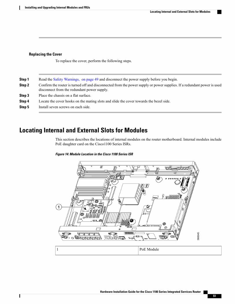
Replacing the Cover
To replace the cover, perform the following steps.
Step 1 Read the Safety Warnings, on page 49 and disconnect the power supply before you begin.Step 2 Confirm the router is turned off and disconnected from the power supply or power supplies. If a redundant power is used
disconnect from the redundant power supply.Step 3 Place the chassis on a flat surface.Step 4 Locate the cover hooks on the mating slots and slide the cover towards the bezel side.Step 5 Install seven screws on each side.
Locating Internal and External Slots for ModulesThis section describes the locations of internal modules on the router motherboard. Internal modules includePoE daughter card on the Cisco1100 Series ISRs.
Figure 14: Module Location in the Cisco 1100 Series ISR
PoE Module1
Hardware Installation Guide for the Cisco 1100 Series Integrated Services Router 51
Installing and Upgrading Internal Modules and FRUsLocating Internal and External Slots for Modules

Installing the Internal PoE Daughter CardUse the following procedure to install an Internal PoE daughter card:
Step 1 Read the Safety Warnings and disconnect the power supply before you perform any module installation.Step 2 Confirm the router is turned off and disconnected from the power supply.Step 3 Open the chassis according to the instructions in the Removing the Chassis section.Step 4 Locate the three metal standoff holes, and install the metal standoffs into the three holes. Make sure that the standoffs
are straight when installed. Tighten them gently but firmly, to a torque of 6-8 in-lbf.Step 5 Place the PoE daughter card on top of the three metal standoffs, lining up the screw holes in the PoE daughter card with
the metal standoffs.Step 6 Gently push the PoE daughter card down towards the system board until it is firmly fixed.Step 7 Insert the three M3 (48-0530-01) screws provided, through the PoE daughter card and into the metal standoffs. Tighten
the screws using a torque of 5 in-lb.Step 8 Close the chassis cover according to the instructions in the Replacing the Cover section, and connect the power supply
cable.
Figure 15: Internal PoE Daughter Card Assembly
PoE Daughter Card2Screws1
Metal Standoffs3
Hardware Installation Guide for the Cisco 1100 Series Integrated Services Router52
Installing and Upgrading Internal Modules and FRUsLocating Internal and External Slots for Modules

Removing and Replacing the Internal PoE Daughter Card
Use the following procedure to remove and replace the Internal PoE daughter card:
Step 1 Read the Safety Warnings and disconnect the power supply before you remove or replace the module.Step 2 Open the chassis, locate the PoE daughter card assembly.Step 3 Remove the three M3 (48-0530-01) screws.Step 4 Pull the PoE daughter card out of the connector. If replacing the card, insert the new PoE daughter card and tighten the
screws to a torque of 5 in-lb.Step 5 Place the removed card in an anti-static bag to protect it from ESD damage.
To upgrade the PoE daughter card, follow the steps mentioned in the Installing the Internal PoE Daughter Cardsection.
Note
Removing and Replacing the USB Flash Token Memory StickThe Cisco 1100 Series ISRs contain port for a 1 GB flash token memory stick to store configurations or CiscoIOS XE consolidated packages.
Only Cisco USB Flash memory modules are supported by Cisco routers.Note
Do not remove a USB Flash memory module when issuing some file access command or a read/writeoperation to the Flash memory module when it is processing. The router might reload or the USB Flashmemory module can be damaged. You can check to see if the USB activity LED on the router front panelis flashing, prior to the removal of the USB device
Caution
To remove and then replace a USB flash token memory stick from the router, follow these steps:
Step 1 Pull the memory stick from the USB port.Step 2 To replace a Cisco USB Flash memory stick, simply insert the module into the USB port. The Flash memory module
can be inserted in only one way, and can be inserted or removed regardless of whether the router is powered up or not.
What to Do Next
This completes the USB Flash memory installation procedure.
Hardware Installation Guide for the Cisco 1100 Series Integrated Services Router 53
Installing and Upgrading Internal Modules and FRUsRemoving and Replacing the USB Flash Token Memory Stick

AC Power Supplies
Overview of the AC Power SupplyPower supply of the Cisco 1100 Series ISRs is an external AC to DC power adapter. The external poweradapter DC power connector plugs in to the router 4-pin power connector, to power the unit.
Figure 16: Power Supply Unit
Power Cable1
Installing and Removing SFP ModulesThis section describes how to install optional small-form-factor pluggable (SFP) modules in the router toprovide optical Gigabit Ethernet connectivity.
The SFPmodule installs into a slot on the router rear panel. When selected in Cisco IOS software, it is assignedport gigabitethernet 0/0/0. The default is the built-in RJ-45 1000Base-T connector, which is enabled on thisport.
Only SFP modules certified by Cisco are supported on the routers.
Table 12: SFPs Supported on the Router
DescriptionMinimumIOS-XE Version
Cisco ModelNumber
1000BASE-EXSFP transceivermodule, SMF,1310nm, DOM
3.15GLC-EX-SMD
Hardware Installation Guide for the Cisco 1100 Series Integrated Services Router54
Installing and Upgrading Internal Modules and FRUsAC Power Supplies

DescriptionMinimumIOS-XE Version
Cisco ModelNumber
GE SFP, LCconnectorLX/LHtransceiver
3.10GLC-LH-SM
9/1251000Base-ZXGLC-ZX-SM-X=
GE SFP, LCconnectorLX/LHtransceiver; withDOM
3.10GLC-LH-SMD
GE SFP, LCconnector SXtransceiver
3.10GLC-SX-MM
GE SFP, LCconnector SXtransceiver; withDOM
3.10GLC-SX-MMD
1000BASE-ZXSFP
3.10GLC-ZX-SM
1000BASE-ZXSFP; with DOM
3.16.1GLC-ZX-SMD
100BASE-FXSFP for FE port
3.10GLC-FE-100FX
100BASE-LXSFP for FE port
3.10GLC-FE-100LX
100BASE-ZXSFP (80km)
3.10GLC-FE-100ZX
100BASE-EXSFP (40km)
3.10GLC-FE-100EX
100BASE-BX10-DSFP
3.11GLC-FE-100BX-D
100BASE-BX10-USFP
3.11GLC-FE-100BX-U
100 V02 SFP onGE ports
3.10GLC-GE-100V02
Hardware Installation Guide for the Cisco 1100 Series Integrated Services Router 55
Installing and Upgrading Internal Modules and FRUsInstalling and Removing SFP Modules

DescriptionMinimumIOS-XE Version
Cisco ModelNumber
1000BASE-BX80SFP, 1570NM
3.16.1GLC-BX80-D-I
1000BASE-BX80SFP, 1490NM
3.16.1GLC-BX80-U-I
1000BASE-BX40SFP, 1550NM
3.16.1GLC-BX40-D-I
1000BASE-BX40SFP, 1310NM
3.16.1GLC-BX40-U-I
1000BASE-BXSFP, 1490NM
3.10GLC-BX-D
1000BASE-BXSFP, 1310NM
3.10GLC-BX-U
1000BASE-SXSFP transceivermodule forMMF, 850-nmwavelength,extendedoperatingtemperaturerange and DOMsupport, dualLC/PCconnector
3.13SFP-GE-S
CWDM 1470NMSFPGigabitEthernet and1G/2G FC
3.10CWDM-SFP-1470
CWDM 1490NMSFPGigabitEthernet and1G/2G FC
3.10CWDM-SFP-1490
CWDM 1510NMSFPGigabitEthernet and1G/2G FC
3.10CWDM-SFP-1510
CWDM 1530NMSFPGigabitEthernet and1G/2G FC
3.10CWDM-SFP-1530
Hardware Installation Guide for the Cisco 1100 Series Integrated Services Router56
Installing and Upgrading Internal Modules and FRUsInstalling and Removing SFP Modules

DescriptionMinimumIOS-XE Version
Cisco ModelNumber
CWDM 1550NMSFPGigabitEthernet and1G/2G FC
3.10CWDM-SFP-1550
CWDM 1570NMSFPGigabitEthernet and1G/2G FC
3.10CWDM-SFP-1570
CWDM 1590NMSFPGigabitEthernet and1G/2G FC
3.10CWDM-SFP-1590
CWDM 1610NMSFPGigabitEthernet and1G/2G FC
3.10CWDM-SFP-1610
DWDM SFP1530.33 nmSFP(100 GHz ITUgrid)
3.10DWDM-SFP-3033
DWDM SFP1531.12 nmSFP(100 GHz ITUgrid)
3.10DWDM-SFP-3112
DWDM SFP1531.90 nmSFP(100 GHz ITUgrid)
3.10DWDM-SFP-3190
DWDM SFP1532.68 nmSFP(100 GHz ITUgrid)
3.10DWDM-SFP-3268
DWDM SFP1534.25 nmSFP(100 GHz ITUgrid)
3.10DWDM-SFP-3425
DWDM SFP1535.04 nmSFP(100 GHz ITUgrid)
3.10DWDM-SFP-3504
Hardware Installation Guide for the Cisco 1100 Series Integrated Services Router 57
Installing and Upgrading Internal Modules and FRUsInstalling and Removing SFP Modules
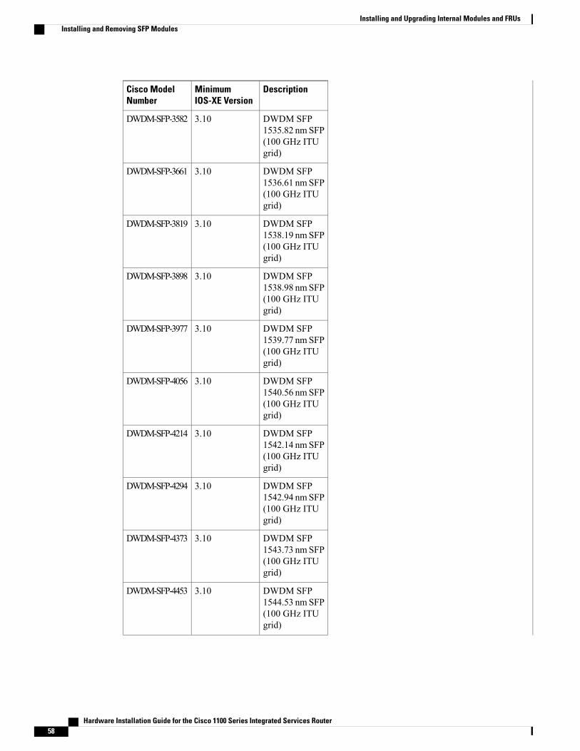
DescriptionMinimumIOS-XE Version
Cisco ModelNumber
DWDM SFP1535.82 nmSFP(100 GHz ITUgrid)
3.10DWDM-SFP-3582
DWDM SFP1536.61 nmSFP(100 GHz ITUgrid)
3.10DWDM-SFP-3661
DWDM SFP1538.19 nmSFP(100 GHz ITUgrid)
3.10DWDM-SFP-3819
DWDM SFP1538.98 nmSFP(100 GHz ITUgrid)
3.10DWDM-SFP-3898
DWDM SFP1539.77 nmSFP(100 GHz ITUgrid)
3.10DWDM-SFP-3977
DWDM SFP1540.56 nmSFP(100 GHz ITUgrid)
3.10DWDM-SFP-4056
DWDM SFP1542.14 nmSFP(100 GHz ITUgrid)
3.10DWDM-SFP-4214
DWDM SFP1542.94 nmSFP(100 GHz ITUgrid)
3.10DWDM-SFP-4294
DWDM SFP1543.73 nmSFP(100 GHz ITUgrid)
3.10DWDM-SFP-4373
DWDM SFP1544.53 nmSFP(100 GHz ITUgrid)
3.10DWDM-SFP-4453
Hardware Installation Guide for the Cisco 1100 Series Integrated Services Router58
Installing and Upgrading Internal Modules and FRUsInstalling and Removing SFP Modules

DescriptionMinimumIOS-XE Version
Cisco ModelNumber
DWDM SFP1546.12 nmSFP(100 GHz ITUgrid)
3.10DWDM-SFP-4612
DWDM SFP1546.92 nmSFP(100 GHz ITUgrid)
3.10DWDM-SFP-4692
DWDM SFP1547.72 nmSFP(100 GHz ITUgrid)
3.10DWDM-SFP-4772
DWDM SFP1548.51 nmSFP(100 GHz ITUgrid)
3.10DWDM-SFP-4851
DWDM SFP1550.12 nmSFP(100 GHz ITUgrid)
3.10DWDM-SFP-5012
DWDM SFP1550.92 nmSFP(100 GHz ITUgrid)
3.10DWDM-SFP-5092
DWDM SFP1551.72 nmSFP(100 GHz ITUgrid)
3.10DWDM-SFP-5172
DWDM SFP1552.52 nmSFP(100 GHz ITUgrid)
3.10DWDM-SFP-5252
DWDM SFP1554.13 nmSFP(100 GHz ITUgrid)
3.10DWDM-SFP-5413
DWDM SFP1554.94 nmSFP(100 GHz ITUgrid)
3.10DWDM-SFP-5494
Hardware Installation Guide for the Cisco 1100 Series Integrated Services Router 59
Installing and Upgrading Internal Modules and FRUsInstalling and Removing SFP Modules
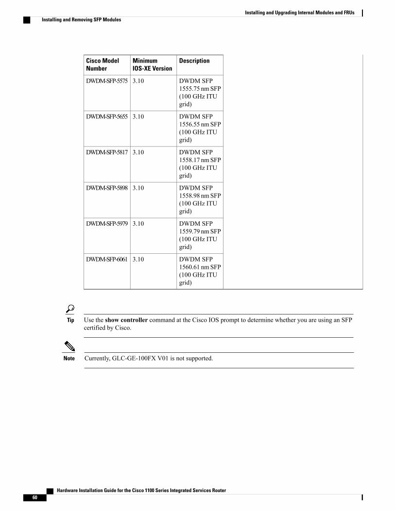
DescriptionMinimumIOS-XE Version
Cisco ModelNumber
DWDM SFP1555.75 nmSFP(100 GHz ITUgrid)
3.10DWDM-SFP-5575
DWDM SFP1556.55 nmSFP(100 GHz ITUgrid)
3.10DWDM-SFP-5655
DWDM SFP1558.17 nmSFP(100 GHz ITUgrid)
3.10DWDM-SFP-5817
DWDM SFP1558.98 nmSFP(100 GHz ITUgrid)
3.10DWDM-SFP-5898
DWDM SFP1559.79 nmSFP(100 GHz ITUgrid)
3.10DWDM-SFP-5979
DWDM SFP1560.61 nmSFP(100 GHz ITUgrid)
3.10DWDM-SFP-6061
Use the show controller command at the Cisco IOS prompt to determine whether you are using an SFPcertified by Cisco.
Tip
Currently, GLC-GE-100FX V01 is not supported.Note
Hardware Installation Guide for the Cisco 1100 Series Integrated Services Router60
Installing and Upgrading Internal Modules and FRUsInstalling and Removing SFP Modules

Installing SFPs
Removing SFP ModulesFollow these steps to remove an SFP from the router:
Step 1 Read the Safety Warnings section and disconnect the power supply before you perform any module replacement.Step 2 Disconnect all cables from the SFP.
Invisible laser radiation may be emitted from disconnected fibers or connectors. Do not stare into beams orview directly with optical instruments. Statement 1051
Warning
The latching mechanism used on many SFPs locks the SFP into place when cables are connected. Do notpull on the cabling in an attempt to remove the SFP.
Caution
Step 3 Disconnect the SFP latch.SFP modules use various latch designs to secure the module in the SFP port. Latch designs are not linked toSFP model or technology type. For information on the SFP technology type and model, see the label on the sideof the SFP.
Note
Use a pen, screwdriver, or other small straight tool to gently release a bale-clasp handle if you cannot reach itwith your fingers.
Tip
Step 4 Grasp the SFP on both sides and remove it from the router.
Hardware Installation Guide for the Cisco 1100 Series Integrated Services Router 61
Installing and Upgrading Internal Modules and FRUsInstalling and Removing SFP Modules

Hardware Installation Guide for the Cisco 1100 Series Integrated Services Router62
Installing and Upgrading Internal Modules and FRUsInstalling and Removing SFP Modules

I N D E X
? command (ROM Monitor) 43, 44
1 GB flash token memory stick 53
C
chassis 31desktop installation 31
confreg command (ROM Monitor) 44displaying configuration register setting 44
connections 20Ethernet 20network 20
D
desktop installation 31
E
environment variables 41, 45, 46displaying 45entering 46introduction 41, 45saving 46
Ethernet cable types 20
H
help command (ROM Monitor) 43
I
installation 18, 20, 31desktop 31site requirements 18tools required tools required for installation 20
L
LAN 20, 38connections 38interface types 20
N
network connections 20
P
packing list 24power 18
requirements 18power supplies 18
requirements 18
R
record keeping, site log 22ROM monitor 46
exiting 46ROMMonitor prompt 41
S
set command (ROM Monitor) 45sync command (ROM Monitor) 46
Hardware Installation Guide for the Cisco 1100 Series Integrated Services Router IN-1

T
Tables 18power requirements 18
W
Warnings 20, 23, 38lightning activity 38restricted access 23SELV circuit 20qualified personnel 23
Hardware Installation Guide for the Cisco 1100 Series Integrated Services RouterIN-2
Index