Embed Size (px)
Citation preview

�
CNC 61.00 Hardware
Series 61.50 - 1 -
Hardware CNC 61.00
Series 61.50
SIEB & MEYER AG
Auf dem Schmaarkamp 21 ’ D-21339 Lüneburg ’ Germany
Telephone: ++49(4131)203-0 ’ Telefax: ++49(4131)203-2000
Email: [email protected]
Internet: www.sieb-meyer.de

�
CNC 61.00 Hardware
- 2 - Series 61.50
The text and the translation of the manual has been worked out very carefully.However, SIEB & MEYER AG can accept neither obligation nor legal responsibility
for incorrect specifications and their consequences,possibly still described in the manual.
Subject to technical alterations!©SIEB & MEYER AG, Lüneburg
061-cnc-tec61.50/R008-sm-en-hg/ca/ac/she/uhApril 04, 2013

� Contents
CNC 61.00 Hardware
Series 61.50 - 3 -
1 Used Symbols and Abbreviations . . . . . . . . . . . . . . . . . . . . . . . . . . . . . . . . 111.1 Units of Measurement . . . . . . . . . . . . . . . . . . . . . . . . . . . . . . . . . . . . . . . . . . . 111.2 Symbols . . . . . . . . . . . . . . . . . . . . . . . . . . . . . . . . . . . . . . . . . . . . . . . . . . . . . . 111.3 Abbreviations . . . . . . . . . . . . . . . . . . . . . . . . . . . . . . . . . . . . . . . . . . . . . . . . . . 121.4 Product Designations . . . . . . . . . . . . . . . . . . . . . . . . . . . . . . . . . . . . . . . . . . . . 13
2 About This Manual . . . . . . . . . . . . . . . . . . . . . . . . . . . . . . . . . . . . . . . . . . . . . 13
3 Safety Instruction and Application Advice . . . . . . . . . . . . . . . . . . . . . . . . . 173.1 General Information . . . . . . . . . . . . . . . . . . . . . . . . . . . . . . . . . . . . . . . . . . . . . 173.2 Appropriate Use . . . . . . . . . . . . . . . . . . . . . . . . . . . . . . . . . . . . . . . . . . . . . . . . 173.2.1 First Environment . . . . . . . . . . . . . . . . . . . . . . . . . . . . . . . . . . . . . . . . . . . . . . . 173.2.2 Second Environment . . . . . . . . . . . . . . . . . . . . . . . . . . . . . . . . . . . . . . . . . . . . 173.2.3 PDS (Power Drive System) of Category C1 . . . . . . . . . . . . . . . . . . . . . . . . . . 183.2.4 PDS of Category C2 . . . . . . . . . . . . . . . . . . . . . . . . . . . . . . . . . . . . . . . . . . . . . 183.2.5 PDS of Category C3 . . . . . . . . . . . . . . . . . . . . . . . . . . . . . . . . . . . . . . . . . . . . . 183.3 Transport and Storage . . . . . . . . . . . . . . . . . . . . . . . . . . . . . . . . . . . . . . . . . . . 203.4 Installation . . . . . . . . . . . . . . . . . . . . . . . . . . . . . . . . . . . . . . . . . . . . . . . . . . . . 203.5 Electrical Connection . . . . . . . . . . . . . . . . . . . . . . . . . . . . . . . . . . . . . . . . . . . . 213.6 Operation . . . . . . . . . . . . . . . . . . . . . . . . . . . . . . . . . . . . . . . . . . . . . . . . . . . . . 223.7 Maintenance . . . . . . . . . . . . . . . . . . . . . . . . . . . . . . . . . . . . . . . . . . . . . . . . . . . 223.8 Guarantee . . . . . . . . . . . . . . . . . . . . . . . . . . . . . . . . . . . . . . . . . . . . . . . . . . . . . 22
4 Unit Assembly Complying EMC . . . . . . . . . . . . . . . . . . . . . . . . . . . . . . . . . . 23
5 Automation System CNC 61.00 . . . . . . . . . . . . . . . . . . . . . . . . . . . . . . . . . . . 235.1 Hardware Design . . . . . . . . . . . . . . . . . . . . . . . . . . . . . . . . . . . . . . . . . . . . . . . 245.2 Programming . . . . . . . . . . . . . . . . . . . . . . . . . . . . . . . . . . . . . . . . . . . . . . . . . . 245.3 Performance Features . . . . . . . . . . . . . . . . . . . . . . . . . . . . . . . . . . . . . . . . . . . 255.4 Views . . . . . . . . . . . . . . . . . . . . . . . . . . . . . . . . . . . . . . . . . . . . . . . . . . . . . . . . 26
6 Mechanical Mounting . . . . . . . . . . . . . . . . . . . . . . . . . . . . . . . . . . . . . . . . . . . 316.1 Replacement of Modules . . . . . . . . . . . . . . . . . . . . . . . . . . . . . . . . . . . . . . . . . 316.2 Mounting of the Back Planes . . . . . . . . . . . . . . . . . . . . . . . . . . . . . . . . . . . . . . 32
7 General Information Regarding the Wiring . . . . . . . . . . . . . . . . . . . . . . . . . 337.1 General Information . . . . . . . . . . . . . . . . . . . . . . . . . . . . . . . . . . . . . . . . . . . . . 337.2 Difficulties of Ground Loops . . . . . . . . . . . . . . . . . . . . . . . . . . . . . . . . . . . . . . . 347.3 Motor Cables . . . . . . . . . . . . . . . . . . . . . . . . . . . . . . . . . . . . . . . . . . . . . . . . . . 357.4 Cables for the First Measuring System . . . . . . . . . . . . . . . . . . . . . . . . . . . . . . 367.5 Cables for the Second Measuring System . . . . . . . . . . . . . . . . . . . . . . . . . . . 367.6
Cables for the Connection of the I/O Expansion Modules . . . . . . . . . . . . . . . 377.7 Cables for the Terminal Connections . . . . . . . . . . . . . . . . . . . . . . . . . . . . . . . 377.8 Cables for the INTERBUS . . . . . . . . . . . . . . . . . . . . . . . . . . . . . . . . . . . . . . . . 377.9 Cables for the External Ballast Resistor . . . . . . . . . . . . . . . . . . . . . . . . . . . . . 377.10 Wiring of the 24 V (Internal/External) . . . . . . . . . . . . . . . . . . . . . . . . . . . . . . . 38
8 Connection Diagrams . . . . . . . . . . . . . . . . . . . . . . . . . . . . . . . . . . . . . . . . . . 398.1 Example: Operation of the CNC 61.50 Directly at the 3-Phase Mains . . . . . . 398.2 Example: Compact System 3-Phase Supply with Autotransformer . . . . . . . . 408.3 Example: Compact System With 1-Phase Supply . . . . . . . . . . . . . . . . . . . . . 41
9 Front Panels . . . . . . . . . . . . . . . . . . . . . . . . . . . . . . . . . . . . . . . . . . . . . . . . . . 439.1 Front Panel of the Multi-Axis System . . . . . . . . . . . . . . . . . . . . . . . . . . . . . . . . 439.2 Front Panel of the Power Module 26.50.65 . . . . . . . . . . . . . . . . . . . . . . . . . . . 449.3 Front Panel of the Compact System . . . . . . . . . . . . . . . . . . . . . . . . . . . . . . . . 459.4 Indications / Connections of the CNC 61.50 Front Panels . . . . . . . . . . . . . . . 469.4.1 Status Indication FC0 to FC3 (Red Flashing) . . . . . . . . . . . . . . . . . . . . . . . . . 469.4.2 Possible Error Causes . . . . . . . . . . . . . . . . . . . . . . . . . . . . . . . . . . . . . . . . . . . 47
�Contents
CNC 61.00 Hardware
- 4 - Series 61.50
9.4.3 Status Indication FC0 to FC3 (Green and Red) . . . . . . . . . . . . . . . . . . . . . . . 539.4.4 RIO - Malfunction Indication . . . . . . . . . . . . . . . . . . . . . . . . . . . . . . . . . . . . . . . 539.4.5 RON- Status of Regulator . . . . . . . . . . . . . . . . . . . . . . . . . . . . . . . . . . . . . . . . 539.4.6 CNC - Operation Indication . . . . . . . . . . . . . . . . . . . . . . . . . . . . . . . . . . . . . . . 539.4.7 REM - Indication “Remote Control” . . . . . . . . . . . . . . . . . . . . . . . . . . . . . . . . . 539.4.8 STX / SRX / SRR - Status Indication/ Error Messages of Bus Systems . . . . . 549.4.9 COM - Connection of Terminal/Programming Unit . . . . . . . . . . . . . . . . . . . . . 559.5 LEDs of the Power Module 26.50.65x . . . . . . . . . . . . . . . . . . . . . . . . . . . . . . . 55
10 Back Planes and Pin Assignment . . . . . . . . . . . . . . . . . . . . . . . . . . . . . . . . 5710.1 Back Planes for the Multi-Axis System . . . . . . . . . . . . . . . . . . . . . . . . . . . . . . 5710.1.1 Back Plane 61.01.0004 for INTERBUS, MODLINK and CAN Bus . . . . . . . . . 57
X1 - Connection of First Measuring System (Feedback) . . . . . . . . . . . . . . . . . 58X2 - Terminal Connection . . . . . . . . . . . . . . . . . . . . . . . . . . . . . . . . . . . . . . . . 59X3 - I/O Expansion . . . . . . . . . . . . . . . . . . . . . . . . . . . . . . . . . . . . . . . . . . . . . . 59X4 - Angle Pulses . . . . . . . . . . . . . . . . . . . . . . . . . . . . . . . . . . . . . . . . . . . . . . . 60X5 - INTERBUS-S Connection . . . . . . . . . . . . . . . . . . . . . . . . . . . . . . . . . . . . 60X6 - INTERBUS-S Connection . . . . . . . . . . . . . . . . . . . . . . . . . . . . . . . . . . . . 61X7 - Angle Pulses . . . . . . . . . . . . . . . . . . . . . . . . . . . . . . . . . . . . . . . . . . . . . . . 61X9 - MODLINK Connection . . . . . . . . . . . . . . . . . . . . . . . . . . . . . . . . . . . . . . . 61X10 - MODLINK Connection . . . . . . . . . . . . . . . . . . . . . . . . . . . . . . . . . . . . . . 62X11 - CAN Bus Connection . . . . . . . . . . . . . . . . . . . . . . . . . . . . . . . . . . . . . . . 62X14 - Transducer/Analog Input . . . . . . . . . . . . . . . . . . . . . . . . . . . . . . . . . . . . 621 to 20 - Logic Signals . . . . . . . . . . . . . . . . . . . . . . . . . . . . . . . . . . . . . . . . . . . 6321 to 24 - Thermal Contact/24 V External . . . . . . . . . . . . . . . . . . . . . . . . . . . . 63U / V / W - Motor Connections . . . . . . . . . . . . . . . . . . . . . . . . . . . . . . . . . . . . . 64Bus - Internal Connection . . . . . . . . . . . . . . . . . . . . . . . . . . . . . . . . . . . . . . . . . 64
10.1.2 Back Plane 61.01.0018 for Profibus . . . . . . . . . . . . . . . . . . . . . . . . . . . . . . . . 65X1 - Connection of First Measuring System (Feedback) . . . . . . . . . . . . . . . . . 66X2 - Terminal Connection . . . . . . . . . . . . . . . . . . . . . . . . . . . . . . . . . . . . . . . . 67X3 - I/O Expansion . . . . . . . . . . . . . . . . . . . . . . . . . . . . . . . . . . . . . . . . . . . . . . 67X4 - Angle Pulses . . . . . . . . . . . . . . . . . . . . . . . . . . . . . . . . . . . . . . . . . . . . . . . 68X5 - Profibus-DP Connection . . . . . . . . . . . . . . . . . . . . . . . . . . . . . . . . . . . . . . 68X6 - Profibus-DP Connection . . . . . . . . . . . . . . . . . . . . . . . . . . . . . . . . . . . . . . 69X7 - Angle Pulses . . . . . . . . . . . . . . . . . . . . . . . . . . . . . . . . . . . . . . . . . . . . . . . 69S1 - Hook Switch . . . . . . . . . . . . . . . . . . . . . . . . . . . . . . . . . . . . . . . . . . . . . . . 691 to 20 - Logic Signals . . . . . . . . . . . . . . . . . . . . . . . . . . . . . . . . . . . . . . . . . . . 7021 to 24 - Transducer/Analog Input . . . . . . . . . . . . . . . . . . . . . . . . . . . . . . . . . 7125 and 26 - Thermal Contact/24 V External . . . . . . . . . . . . . . . . . . . . . . . . . . 71U / V / W - Motor Connections . . . . . . . . . . . . . . . . . . . . . . . . . . . . . . . . . . . . . 71Bus - Internal Connection . . . . . . . . . . . . . . . . . . . . . . . . . . . . . . . . . . . . . . . . . 71
10.1.3 Back Plane 61.01.0037 for Profibus and CAN Bus . . . . . . . . . . . . . . . . . . . . . 73X1 - Connection of First Measuring System (Feedback) . . . . . . . . . . . . . . . . . 74X2 - Terminal Connection . . . . . . . . . . . . . . . . . . . . . . . . . . . . . . . . . . . . . . . . 75X3 - I/O Expansion . . . . . . . . . . . . . . . . . . . . . . . . . . . . . . . . . . . . . . . . . . . . . . 75X4 - Angle Pulses . . . . . . . . . . . . . . . . . . . . . . . . . . . . . . . . . . . . . . . . . . . . . . . 76X7 - Angle Pulses . . . . . . . . . . . . . . . . . . . . . . . . . . . . . . . . . . . . . . . . . . . . . . . 76X11 - CAN Bus Connection . . . . . . . . . . . . . . . . . . . . . . . . . . . . . . . . . . . . . . . 77X14 - Transducer/Analog Input . . . . . . . . . . . . . . . . . . . . . . . . . . . . . . . . . . . . 77X19 - Profibus-DP Connection . . . . . . . . . . . . . . . . . . . . . . . . . . . . . . . . . . . . . 77X21 - Serial Interfaces 2 and 3 . . . . . . . . . . . . . . . . . . . . . . . . . . . . . . . . . . . . 781 to 20 - Logic Signals . . . . . . . . . . . . . . . . . . . . . . . . . . . . . . . . . . . . . . . . . . . 7821 to 24 - Thermal Contact/24 V External . . . . . . . . . . . . . . . . . . . . . . . . . . . . 79U / V / W - Motor Connections . . . . . . . . . . . . . . . . . . . . . . . . . . . . . . . . . . . . . 79Bus - Internal Connection . . . . . . . . . . . . . . . . . . . . . . . . . . . . . . . . . . . . . . . . . 79
10.1.4 Back Plane 61.01.0038 . . . . . . . . . . . . . . . . . . . . . . . . . . . . . . . . . . . . . . . . . . 80X1 - Connection of First Measuring System (Feedback) . . . . . . . . . . . . . . . . . 81X2 - Terminal Connection . . . . . . . . . . . . . . . . . . . . . . . . . . . . . . . . . . . . . . . . 82X3 - I/O Expansion . . . . . . . . . . . . . . . . . . . . . . . . . . . . . . . . . . . . . . . . . . . . . . 82
� Contents
CNC 61.00 Hardware
Series 61.50 - 5 -
X4 - Angle Pulses . . . . . . . . . . . . . . . . . . . . . . . . . . . . . . . . . . . . . . . . . . . . . . . 83X5 - Bus Connection . . . . . . . . . . . . . . . . . . . . . . . . . . . . . . . . . . . . . . . . . . . . 83X6 - Bus Connection . . . . . . . . . . . . . . . . . . . . . . . . . . . . . . . . . . . . . . . . . . . . 84X7 - Angle Pulses . . . . . . . . . . . . . . . . . . . . . . . . . . . . . . . . . . . . . . . . . . . . . . . 84S1 - Hook Switch . . . . . . . . . . . . . . . . . . . . . . . . . . . . . . . . . . . . . . . . . . . . . . . 841 to 20 - Logic Signals . . . . . . . . . . . . . . . . . . . . . . . . . . . . . . . . . . . . . . . . . . . 8521 to 24 - Transducer/Analog Input . . . . . . . . . . . . . . . . . . . . . . . . . . . . . . . . . 8625 and 26 - Thermal Contact/24 V External . . . . . . . . . . . . . . . . . . . . . . . . . . 86U / V / W - Motor Connections . . . . . . . . . . . . . . . . . . . . . . . . . . . . . . . . . . . . . 86Bus - Internal Connection . . . . . . . . . . . . . . . . . . . . . . . . . . . . . . . . . . . . . . . . . 87
10.1.5 Back Plane 61.01.0053 for Profibus, CAN Bus and Ethernet . . . . . . . . . . . . . 88X1 - Connection of First Measuring System (Feedback) . . . . . . . . . . . . . . . . . 89X2 - Terminal Connection . . . . . . . . . . . . . . . . . . . . . . . . . . . . . . . . . . . . . . . . 90X3 - I/O Expansion . . . . . . . . . . . . . . . . . . . . . . . . . . . . . . . . . . . . . . . . . . . . . . 90X4 - Angle Pulses . . . . . . . . . . . . . . . . . . . . . . . . . . . . . . . . . . . . . . . . . . . . . . . 91X5 - Profibus Connection . . . . . . . . . . . . . . . . . . . . . . . . . . . . . . . . . . . . . . . . . 91X6 - Profibus Connection . . . . . . . . . . . . . . . . . . . . . . . . . . . . . . . . . . . . . . . . . 92X7 - Angle Pulses . . . . . . . . . . . . . . . . . . . . . . . . . . . . . . . . . . . . . . . . . . . . . . . 92X11 - CAN Bus Connection . . . . . . . . . . . . . . . . . . . . . . . . . . . . . . . . . . . . . . . 92X15 - Active/Passive Transducer . . . . . . . . . . . . . . . . . . . . . . . . . . . . . . . . . . . 93X33 - Ethernet Connection . . . . . . . . . . . . . . . . . . . . . . . . . . . . . . . . . . . . . . . . 931 to 20 - Logic Signals . . . . . . . . . . . . . . . . . . . . . . . . . . . . . . . . . . . . . . . . . . . 9421 to 24 - Thermal Contact/24 V External . . . . . . . . . . . . . . . . . . . . . . . . . . . . 94U / V / W - Motor Connections . . . . . . . . . . . . . . . . . . . . . . . . . . . . . . . . . . . . . 95Bus - Internal Connection . . . . . . . . . . . . . . . . . . . . . . . . . . . . . . . . . . . . . . . . . 95
10.1.6 Back Plane 61.01.0058 for Profibus, CAN Bus and Ethernet . . . . . . . . . . . . . 96X1 - Connection of First Measuring System (Feedback) . . . . . . . . . . . . . . . . . 97X2 - Terminal Connection . . . . . . . . . . . . . . . . . . . . . . . . . . . . . . . . . . . . . . . . 98X3 - I/O Expansion . . . . . . . . . . . . . . . . . . . . . . . . . . . . . . . . . . . . . . . . . . . . . . 98X4 - Angle Pulses . . . . . . . . . . . . . . . . . . . . . . . . . . . . . . . . . . . . . . . . . . . . . . . 99X7 - Angle Pulses . . . . . . . . . . . . . . . . . . . . . . . . . . . . . . . . . . . . . . . . . . . . . . . 99X11 - CAN Bus Connection . . . . . . . . . . . . . . . . . . . . . . . . . . . . . . . . . . . . . 100X15 - Active/Passive Transducer . . . . . . . . . . . . . . . . . . . . . . . . . . . . . . . . . 100X19 - Profibus Connection . . . . . . . . . . . . . . . . . . . . . . . . . . . . . . . . . . . . . . 100X21 - Serial Interfaces 2 and 3 . . . . . . . . . . . . . . . . . . . . . . . . . . . . . . . . . . 101X33 - Ethernet Connection . . . . . . . . . . . . . . . . . . . . . . . . . . . . . . . . . . . . . . 1011 to 20 - Logic Signals . . . . . . . . . . . . . . . . . . . . . . . . . . . . . . . . . . . . . . . . . 10221 to 24 - Thermal Contact/24 V External . . . . . . . . . . . . . . . . . . . . . . . . . . 102U / V / W - Motor Connection . . . . . . . . . . . . . . . . . . . . . . . . . . . . . . . . . . . . 103Bus - Internal Connection . . . . . . . . . . . . . . . . . . . . . . . . . . . . . . . . . . . . . . . 103
10.1.7 Back Plane 61.01.0060 for INTERBUS, MODLINK and CAN Bus . . . . . . . 104X1 - Connection of First Measuring System (Feedback) . . . . . . . . . . . . . . . 105X2 - Terminal Connection . . . . . . . . . . . . . . . . . . . . . . . . . . . . . . . . . . . . . . 106X3 - I/O Expansion . . . . . . . . . . . . . . . . . . . . . . . . . . . . . . . . . . . . . . . . . . . . 106X4 - Angle Pulses . . . . . . . . . . . . . . . . . . . . . . . . . . . . . . . . . . . . . . . . . . . . . 107X5 - INTERBUS Connection . . . . . . . . . . . . . . . . . . . . . . . . . . . . . . . . . . . . 107X6 - INTERBUS Connection . . . . . . . . . . . . . . . . . . . . . . . . . . . . . . . . . . . . 108X7 - Angle Pulses . . . . . . . . . . . . . . . . . . . . . . . . . . . . . . . . . . . . . . . . . . . . . 108X9 - MODLINK Connection . . . . . . . . . . . . . . . . . . . . . . . . . . . . . . . . . . . . . 108X10 - MODLINK Connection . . . . . . . . . . . . . . . . . . . . . . . . . . . . . . . . . . . . 109X11 - CAN Bus Connection . . . . . . . . . . . . . . . . . . . . . . . . . . . . . . . . . . . . . 109X14 - Transducer/Analog Input . . . . . . . . . . . . . . . . . . . . . . . . . . . . . . . . . . 109X33 - Ethernet Connection . . . . . . . . . . . . . . . . . . . . . . . . . . . . . . . . . . . . . . 1101 to 20 - Logic Signals . . . . . . . . . . . . . . . . . . . . . . . . . . . . . . . . . . . . . . . . . 11021 to 24 - Thermal Contact/24 V External . . . . . . . . . . . . . . . . . . . . . . . . . . 112U / V / W - Motor Connection . . . . . . . . . . . . . . . . . . . . . . . . . . . . . . . . . . . . 112Bus - Internal Connection . . . . . . . . . . . . . . . . . . . . . . . . . . . . . . . . . . . . . . . 112
10.2 Back Planes for the Compact System . . . . . . . . . . . . . . . . . . . . . . . . . . . . . 11510.2.1 Back Plane 61.01.0019 . . . . . . . . . . . . . . . . . . . . . . . . . . . . . . . . . . . . . . . . 115
�Contents
CNC 61.00 Hardware
- 6 - Series 61.50
X1 - Connection of First Measuring System (Feedback) . . . . . . . . . . . . . . . 116X2 - Terminal Connection . . . . . . . . . . . . . . . . . . . . . . . . . . . . . . . . . . . . . . 117X3 - I/O Expansion . . . . . . . . . . . . . . . . . . . . . . . . . . . . . . . . . . . . . . . . . . . . 117X4 - Angle Pulses . . . . . . . . . . . . . . . . . . . . . . . . . . . . . . . . . . . . . . . . . . . . . 118X5 - Bus Connection . . . . . . . . . . . . . . . . . . . . . . . . . . . . . . . . . . . . . . . . . . 119X6 - Bus Connection . . . . . . . . . . . . . . . . . . . . . . . . . . . . . . . . . . . . . . . . . . 119X7 - Angle Pulses . . . . . . . . . . . . . . . . . . . . . . . . . . . . . . . . . . . . . . . . . . . . . 120X8 - Profibus-DP Connection . . . . . . . . . . . . . . . . . . . . . . . . . . . . . . . . . . . . 120S1 - Hook Switch . . . . . . . . . . . . . . . . . . . . . . . . . . . . . . . . . . . . . . . . . . . . . 120U / V / W / PE - Motor Connections . . . . . . . . . . . . . . . . . . . . . . . . . . . . . . . 1211 to 20 - Logic Signals . . . . . . . . . . . . . . . . . . . . . . . . . . . . . . . . . . . . . . . . . 12121 to 24 - Transducer/Analog Input . . . . . . . . . . . . . . . . . . . . . . . . . . . . . . . 12225 and 26 - Thermal Contact/24 V External . . . . . . . . . . . . . . . . . . . . . . . . 122L1 / L2 / L3 - Main Supply . . . . . . . . . . . . . . . . . . . . . . . . . . . . . . . . . . . . . . 122L1 / L2 - Mains Input for the Logic Supply . . . . . . . . . . . . . . . . . . . . . . . . . . 123Rex
- External Ballast Resistor . . . . . . . . . . . . . . . . . . . . . . . . . . . . . . . . . . . 12310.2.2 Back Plane 61.01.0028 . . . . . . . . . . . . . . . . . . . . . . . . . . . . . . . . . . . . . . . . 124
X1 - Connection of First Measuring System (Feedback) . . . . . . . . . . . . . . . 125X2 - Terminal Connection . . . . . . . . . . . . . . . . . . . . . . . . . . . . . . . . . . . . . . 126X3 - I/O Expansion . . . . . . . . . . . . . . . . . . . . . . . . . . . . . . . . . . . . . . . . . . . . 126X4 - Angle Pulses . . . . . . . . . . . . . . . . . . . . . . . . . . . . . . . . . . . . . . . . . . . . . 127X5 - INTERBUS-S Connection . . . . . . . . . . . . . . . . . . . . . . . . . . . . . . . . . . 127X6 - INTERBUS-S Connection . . . . . . . . . . . . . . . . . . . . . . . . . . . . . . . . . . 128X8 - Transducer Connection . . . . . . . . . . . . . . . . . . . . . . . . . . . . . . . . . . . . 128X9 - MODLINK Connection . . . . . . . . . . . . . . . . . . . . . . . . . . . . . . . . . . . . . 128X10 - MODLINK Connection . . . . . . . . . . . . . . . . . . . . . . . . . . . . . . . . . . . . 129X19 - Profibus-DP Connection . . . . . . . . . . . . . . . . . . . . . . . . . . . . . . . . . . . 129X21 - Serial Interfaces 2 and 3 . . . . . . . . . . . . . . . . . . . . . . . . . . . . . . . . . . 129X31 - CAN Bus Connection . . . . . . . . . . . . . . . . . . . . . . . . . . . . . . . . . . . . . 129U / V / W / PE - Motor Connections . . . . . . . . . . . . . . . . . . . . . . . . . . . . . . . 1301 to 20 - Logic Signals . . . . . . . . . . . . . . . . . . . . . . . . . . . . . . . . . . . . . . . . . 13021 to 24 - Thermal Contact/24 V External . . . . . . . . . . . . . . . . . . . . . . . . . . 131L1 / L2 / L3 - Main Supply . . . . . . . . . . . . . . . . . . . . . . . . . . . . . . . . . . . . . . 131L1 / L2 - Mains Input for the Logic Supply . . . . . . . . . . . . . . . . . . . . . . . . . . 132Rex - External Ballast Resistor . . . . . . . . . . . . . . . . . . . . . . . . . . . . . . . . . . . 132
10.2.3 Back Plane 61.01.0051 . . . . . . . . . . . . . . . . . . . . . . . . . . . . . . . . . . . . . . . . 133X1 - Connection of First Measuring System (Feedback) . . . . . . . . . . . . . . . 134X2 - Terminal Connection . . . . . . . . . . . . . . . . . . . . . . . . . . . . . . . . . . . . . . 135X3 - I/O Expansion . . . . . . . . . . . . . . . . . . . . . . . . . . . . . . . . . . . . . . . . . . . . 135X4 - Angle Pulses . . . . . . . . . . . . . . . . . . . . . . . . . . . . . . . . . . . . . . . . . . . . . 136X7 - Angle Pulses . . . . . . . . . . . . . . . . . . . . . . . . . . . . . . . . . . . . . . . . . . . . . 136X15 - Active/Passive Transducer . . . . . . . . . . . . . . . . . . . . . . . . . . . . . . . . . 137X19 - Profibus Connection . . . . . . . . . . . . . . . . . . . . . . . . . . . . . . . . . . . . . . 137X21 - Serial Interfaces 2 and 3 . . . . . . . . . . . . . . . . . . . . . . . . . . . . . . . . . . 137X31 - CAN Bus Connection . . . . . . . . . . . . . . . . . . . . . . . . . . . . . . . . . . . . . 138X33 - Ethernet Connection . . . . . . . . . . . . . . . . . . . . . . . . . . . . . . . . . . . . . . 138U / V / W - Motor Connections . . . . . . . . . . . . . . . . . . . . . . . . . . . . . . . . . . . 1381 to 20 - Logic Signals . . . . . . . . . . . . . . . . . . . . . . . . . . . . . . . . . . . . . . . . . 13921 to 24 - Thermal Contact/24 V External . . . . . . . . . . . . . . . . . . . . . . . . . . 139L1 / L2 / L3 - Main Supply . . . . . . . . . . . . . . . . . . . . . . . . . . . . . . . . . . . . . . 140L1 / L2 - Mains Input for the Logic Supply . . . . . . . . . . . . . . . . . . . . . . . . . . 140REX - External Ballast Resistor . . . . . . . . . . . . . . . . . . . . . . . . . . . . . . . . . . . 142
10.2.4 Back Plane 61.01.0057 . . . . . . . . . . . . . . . . . . . . . . . . . . . . . . . . . . . . . . . . 143X1 - Connection of First Measuring System (Feedback) . . . . . . . . . . . . . . . 144X2 - Terminal Connection . . . . . . . . . . . . . . . . . . . . . . . . . . . . . . . . . . . . . . 145X3 - I/O Expansion . . . . . . . . . . . . . . . . . . . . . . . . . . . . . . . . . . . . . . . . . . . . 145X4 - Angle Pulses . . . . . . . . . . . . . . . . . . . . . . . . . . . . . . . . . . . . . . . . . . . . . 146X7 - Angle Pulses . . . . . . . . . . . . . . . . . . . . . . . . . . . . . . . . . . . . . . . . . . . . . 146X15 - Active/Passive Transducer . . . . . . . . . . . . . . . . . . . . . . . . . . . . . . . . . 147

� Contents
CNC 61.00 Hardware
Series 61.50 - 7 -
X33 - Ethernet Connection . . . . . . . . . . . . . . . . . . . . . . . . . . . . . . . . . . . . . . 147S1 - Hook Switch . . . . . . . . . . . . . . . . . . . . . . . . . . . . . . . . . . . . . . . . . . . . . 147U / V / W - Motor Connection . . . . . . . . . . . . . . . . . . . . . . . . . . . . . . . . . . . . 1481 to 20 - Logic Signals . . . . . . . . . . . . . . . . . . . . . . . . . . . . . . . . . . . . . . . . . 14821 to 24 - Transducer/Analog Input . . . . . . . . . . . . . . . . . . . . . . . . . . . . . . . 14925 and 26 - Thermal Contact/24 V External . . . . . . . . . . . . . . . . . . . . . . . . 149L1 / L2 / L3 - Main Supply . . . . . . . . . . . . . . . . . . . . . . . . . . . . . . . . . . . . . . 149L1 / L2 - Mains Input for the Logic Supply . . . . . . . . . . . . . . . . . . . . . . . . . . 150REX
- External Ballast Resistor . . . . . . . . . . . . . . . . . . . . . . . . . . . . . . . . . . . 15010.3 Back Planes of the Power Module 26.50.65 . . . . . . . . . . . . . . . . . . . . . . . . 15110.3.1 Back Plane 61.01.0017 . . . . . . . . . . . . . . . . . . . . . . . . . . . . . . . . . . . . . . . . 151
L1 / L2 / L3 - Main Supply . . . . . . . . . . . . . . . . . . . . . . . . . . . . . . . . . . . . . . 152L1 / L2 - Mains Input for the Logic Supply . . . . . . . . . . . . . . . . . . . . . . . . . . 152X12 - POK and BB . . . . . . . . . . . . . . . . . . . . . . . . . . . . . . . . . . . . . . . . . . . . 153Rex - External Ballast Resistor . . . . . . . . . . . . . . . . . . . . . . . . . . . . . . . . . . . 154Bus - Internal Connection . . . . . . . . . . . . . . . . . . . . . . . . . . . . . . . . . . . . . . . 154
10.3.2 Back Plane 61.01.0061 . . . . . . . . . . . . . . . . . . . . . . . . . . . . . . . . . . . . . . . . 156L1 / L2 / L3 - Main Supply . . . . . . . . . . . . . . . . . . . . . . . . . . . . . . . . . . . . . . 157L1 / L2 - Mains Input for the Logic Supply . . . . . . . . . . . . . . . . . . . . . . . . . . 157X12 - POK and BB . . . . . . . . . . . . . . . . . . . . . . . . . . . . . . . . . . . . . . . . . . . . 158REX
- External Ballast Resistor . . . . . . . . . . . . . . . . . . . . . . . . . . . . . . . . . . . 159N . . . . . . . . . . . . . . . . . . . . . . . . . . . . . . . . . . . . . . . . . . . . . . . . . . . . . . . . . . 159Bus - Internal Connection . . . . . . . . . . . . . . . . . . . . . . . . . . . . . . . . . . . . . . . 159
10.3.3 Back Plane 26.50.0078 . . . . . . . . . . . . . . . . . . . . . . . . . . . . . . . . . . . . . . . . 161L1 / L2 / L3 - Main Supply . . . . . . . . . . . . . . . . . . . . . . . . . . . . . . . . . . . . . . 162L1 / L2 - Mains Input for the Logic Supply . . . . . . . . . . . . . . . . . . . . . . . . . . 162POK and BB . . . . . . . . . . . . . . . . . . . . . . . . . . . . . . . . . . . . . . . . . . . . . . . . . 163REX - External Ballast Resistor . . . . . . . . . . . . . . . . . . . . . . . . . . . . . . . . . . . 164N . . . . . . . . . . . . . . . . . . . . . . . . . . . . . . . . . . . . . . . . . . . . . . . . . . . . . . . . . . 164Bus - Internal Connection . . . . . . . . . . . . . . . . . . . . . . . . . . . . . . . . . . . . . . . 164
11 Accessory Modules . . . . . . . . . . . . . . . . . . . . . . . . . . . . . . . . . . . . . . . . . . 16711.1 Mounting of the Accessory Modules . . . . . . . . . . . . . . . . . . . . . . . . . . . . . . 16811.2 A1 - INTERBUS Interface . . . . . . . . . . . . . . . . . . . . . . . . . . . . . . . . . . . . . . 16911.3 A2 - Second Serial Interface . . . . . . . . . . . . . . . . . . . . . . . . . . . . . . . . . . . . 17011.4 A3 - Transducer Interface . . . . . . . . . . . . . . . . . . . . . . . . . . . . . . . . . . . . . . 17011.5 A4 - Analog Input Module . . . . . . . . . . . . . . . . . . . . . . . . . . . . . . . . . . . . . . . 17211.6 A5 - Transducer Interface and Second Serial Interface . . . . . . . . . . . . . . . 17411.7 A6 - Analog Input Module and Second Serial Interface . . . . . . . . . . . . . . . 17611.8 AA - Transducer and Two Serial Interfaces . . . . . . . . . . . . . . . . . . . . . . . . . 17711.9 AB - Profibus Interface . . . . . . . . . . . . . . . . . . . . . . . . . . . . . . . . . . . . . . . . . 17811.10 AE - Transducer and Profibus Interface . . . . . . . . . . . . . . . . . . . . . . . . . . . 17811.11 AF - Active Transducer and Profibus Interface . . . . . . . . . . . . . . . . . . . . . . 18111.12 AG – Passive Twin Transducer . . . . . . . . . . . . . . . . . . . . . . . . . . . . . . . . . . 18211.13 AH - Active Twin Transducer . . . . . . . . . . . . . . . . . . . . . . . . . . . . . . . . . . . . 18411.14 B - Universal Angle Pulse Module . . . . . . . . . . . . . . . . . . . . . . . . . . . . . . . . 18711.15 B1/B2 - Incremental Encoder Interface . . . . . . . . . . . . . . . . . . . . . . . . . . . . 18911.16 B3 - Angle Pulse Output Module 5 V Level . . . . . . . . . . . . . . . . . . . . . . . . . 19011.17 B4 - Angle Pulse Input and Output Module . . . . . . . . . . . . . . . . . . . . . . . . . 19011.18 B5 - Angle Pulse Input Module, 2-Fold, 5 V Level . . . . . . . . . . . . . . . . . . . . 19011.19 B7/B8 - Counter Input and Angle Pulse Output . . . . . . . . . . . . . . . . . . . . . . 19111.20 B9 - Angle Pulse Input Module, 2-Fold, 5 V/24 V Levels . . . . . . . . . . . . . . 19211.21 BA - Angle Pulse Input 24 V / Angle Pulse Output 5 V . . . . . . . . . . . . . . . . 19211.22 C1 - I/O Expansion Interface . . . . . . . . . . . . . . . . . . . . . . . . . . . . . . . . . . . . 19311.23 C2/C3 - SSI Interface, Angle Pulse Input and IO Expansion . . . . . . . . . . . 19411.24 C4 - SSI Interface, I/O Expansion and Angle Pulse Output 5 V . . . . . . . . . 19511.25 D1 - CAN Bus Interface . . . . . . . . . . . . . . . . . . . . . . . . . . . . . . . . . . . . . . . . 19511.26 E1 - Battery-Buffered RAM and Real Time Clock . . . . . . . . . . . . . . . . . . . . 19711.27 F1 - MODLINK Interface . . . . . . . . . . . . . . . . . . . . . . . . . . . . . . . . . . . . . . . 19811.28 G1 - Ethernet Interface . . . . . . . . . . . . . . . . . . . . . . . . . . . . . . . . . . . . . . . . . 198

�Contents
CNC 61.00 Hardware
- 8 - Series 61.50
12 External I/O Modules . . . . . . . . . . . . . . . . . . . . . . . . . . . . . . . . . . . . . . . . . 20112.1 I/O Modules 44.20.xx . . . . . . . . . . . . . . . . . . . . . . . . . . . . . . . . . . . . . . . . . . 20212.1.1 Connection Example . . . . . . . . . . . . . . . . . . . . . . . . . . . . . . . . . . . . . . . . . . 20212.1.2 I/O Basic Module 44.20.012 . . . . . . . . . . . . . . . . . . . . . . . . . . . . . . . . . . . . . 20312.1.3 Output Module 44.20.013 . . . . . . . . . . . . . . . . . . . . . . . . . . . . . . . . . . . . . . . 20412.1.4 Input Module 44.20.014 . . . . . . . . . . . . . . . . . . . . . . . . . . . . . . . . . . . . . . . . 20512.1.5 Output Interface 44.20.028 . . . . . . . . . . . . . . . . . . . . . . . . . . . . . . . . . . . . . 20612.1.6 Output Interface 44.20.051 . . . . . . . . . . . . . . . . . . . . . . . . . . . . . . . . . . . . . 20712.1.7 Output Interface 44.20.053 . . . . . . . . . . . . . . . . . . . . . . . . . . . . . . . . . . . . . 20812.1.8 I/O Multi-Purpose Module 44.20.008 . . . . . . . . . . . . . . . . . . . . . . . . . . . . . . 20912.1.9 I/O Multi-Purpose Module 44.20.008B . . . . . . . . . . . . . . . . . . . . . . . . . . . . . 21112.2 Components of the Standard I/O System 50.06 . . . . . . . . . . . . . . . . . . . . . 21312.3 Dimensions . . . . . . . . . . . . . . . . . . . . . . . . . . . . . . . . . . . . . . . . . . . . . . . . . . 21312.4 Mother Board . . . . . . . . . . . . . . . . . . . . . . . . . . . . . . . . . . . . . . . . . . . . . . . . 21412.4.1 Wiring of the In- and Outputs on the Mother Board . . . . . . . . . . . . . . . . . . . 217
Inputs . . . . . . . . . . . . . . . . . . . . . . . . . . . . . . . . . . . . . . . . . . . . . . . . . . . . . . 217Outputs (Low-Side) . . . . . . . . . . . . . . . . . . . . . . . . . . . . . . . . . . . . . . . . . . . 217Bidirectional In- and Outputs (Low-Side) . . . . . . . . . . . . . . . . . . . . . . . . . . . 217Outputs (High-Side) . . . . . . . . . . . . . . . . . . . . . . . . . . . . . . . . . . . . . . . . . . . 218Maximum Permissible Load of the In- and Outputs . . . . . . . . . . . . . . . . . . 218Interlocking the Outputs . . . . . . . . . . . . . . . . . . . . . . . . . . . . . . . . . . . . . . . . 220
12.5 Basic Plug-In PCB 50.06.0200.x . . . . . . . . . . . . . . . . . . . . . . . . . . . . . . . . . 22112.6 Customized PCB 50.06.01xx.x . . . . . . . . . . . . . . . . . . . . . . . . . . . . . . . . . . 22212.6.1 50.06.0100.x . . . . . . . . . . . . . . . . . . . . . . . . . . . . . . . . . . . . . . . . . . . . . . . . . 222
Wiring of the In- and Outputs on the PCB 50.06.0100.x . . . . . . . . . . . . . . . 22312.7 IO Modules . . . . . . . . . . . . . . . . . . . . . . . . . . . . . . . . . . . . . . . . . . . . . . . . . . 22312.8 Module Designations . . . . . . . . . . . . . . . . . . . . . . . . . . . . . . . . . . . . . . . . . . 22412.8.1 Module 50.06.1x . . . . . . . . . . . . . . . . . . . . . . . . . . . . . . . . . . . . . . . . . . . . . . 22412.8.2 Module 50.06.2x . . . . . . . . . . . . . . . . . . . . . . . . . . . . . . . . . . . . . . . . . . . . . . 22512.8.3 Modul 50.06.3x . . . . . . . . . . . . . . . . . . . . . . . . . . . . . . . . . . . . . . . . . . . . . . . 22512.8.4 Module 50.06.1xx . . . . . . . . . . . . . . . . . . . . . . . . . . . . . . . . . . . . . . . . . . . . . 22512.8.5 Module 50.06.2xx . . . . . . . . . . . . . . . . . . . . . . . . . . . . . . . . . . . . . . . . . . . . . 22612.8.6 Module 50.06.3xx . . . . . . . . . . . . . . . . . . . . . . . . . . . . . . . . . . . . . . . . . . . . . 22612.8.7 Module 50.06.4xx . . . . . . . . . . . . . . . . . . . . . . . . . . . . . . . . . . . . . . . . . . . . . 22612.8.8 Module 50.06.5xx . . . . . . . . . . . . . . . . . . . . . . . . . . . . . . . . . . . . . . . . . . . . . 22612.9 Assignment of the Physical Connections . . . . . . . . . . . . . . . . . . . . . . . . . . 22712.9.1 Examples . . . . . . . . . . . . . . . . . . . . . . . . . . . . . . . . . . . . . . . . . . . . . . . . . . . 228
50.06.12 . . . . . . . . . . . . . . . . . . . . . . . . . . . . . . . . . . . . . . . . . . . . . . . . . . . . 22950.06.14 . . . . . . . . . . . . . . . . . . . . . . . . . . . . . . . . . . . . . . . . . . . . . . . . . . . . 22950.06.20 . . . . . . . . . . . . . . . . . . . . . . . . . . . . . . . . . . . . . . . . . . . . . . . . . . . . 23050.06.104 . . . . . . . . . . . . . . . . . . . . . . . . . . . . . . . . . . . . . . . . . . . . . . . . . . . 23050.06.130 . . . . . . . . . . . . . . . . . . . . . . . . . . . . . . . . . . . . . . . . . . . . . . . . . . . 23150.06.203 . . . . . . . . . . . . . . . . . . . . . . . . . . . . . . . . . . . . . . . . . . . . . . . . . . . 23150.06.300 . . . . . . . . . . . . . . . . . . . . . . . . . . . . . . . . . . . . . . . . . . . . . . . . . . . 232
13 The Logic Cards . . . . . . . . . . . . . . . . . . . . . . . . . . . . . . . . . . . . . . . . . . . . . 23313.1 Logic Card 61.01.0003 (Resolver Evaluation, Trapezoidal Commutation) . 23313.2 Logic Card 61.01.0022 (Resolver Evaluation, Sinusoidal Commutation) . . 23413.3 Logic Card 61.01.0023 (Synchron. Linear Motors, Sinusoidal Comm.) . . . 23513.4 Logic Card 61.01.0027 (Hall Effect Sensor Eval., Trapezoidal Comm.) . . . 236
14 Cables . . . . . . . . . . . . . . . . . . . . . . . . . . . . . . . . . . . . . . . . . . . . . . . . . . . . . 23714.1 Cable K61.02.xxx - Connection to the IO Expansion . . . . . . . . . . . . . . . . . 23714.2 Cable K61.04.xxx - Communication between PC and CNC 61.00 . . . . . . . 23814.3 Cable K61.08.xxx - INTERBUS-S Remote Bus Cable . . . . . . . . . . . . . . . . 23914.4 Cable K61.11.xxx - MODLINK Cable . . . . . . . . . . . . . . . . . . . . . . . . . . . . . . 24014.5 Cable K61.13.xxx - Connecting Cable for IO Expansion . . . . . . . . . . . . . . 24114.6 Cable K61.14.xxx - Comm. between CNC 61.00 and CIMREX30 Terminal 242

� Contents
CNC 61.00 Hardware
Series 61.50 - 9 -
15 Technical Data . . . . . . . . . . . . . . . . . . . . . . . . . . . . . . . . . . . . . . . . . . . . . . 24315.1 Multi-Axis Modules of Series 61.50 . . . . . . . . . . . . . . . . . . . . . . . . . . . . . . . 24315.1.1 Up to 325 VDC
Intermediate Circuit Voltage . . . . . . . . . . . . . . . . . . . . . . . . . 24315.1.2 Up to 560 VDC
Intermediate Circuit Voltage . . . . . . . . . . . . . . . . . . . . . . . . . 24415.1.3 Power Module 26.50.65x . . . . . . . . . . . . . . . . . . . . . . . . . . . . . . . . . . . . . . . 24515.1.4 Back Planes . . . . . . . . . . . . . . . . . . . . . . . . . . . . . . . . . . . . . . . . . . . . . . . . . 246
Multi-Axis Modules of Series 61.50 . . . . . . . . . . . . . . . . . . . . . . . . . . . . . . . 246Power Module 26.50.65x . . . . . . . . . . . . . . . . . . . . . . . . . . . . . . . . . . . . . . . 246
15.2 Compact Modules of Series 61.50 . . . . . . . . . . . . . . . . . . . . . . . . . . . . . . . . 24715.2.1 Back Planes . . . . . . . . . . . . . . . . . . . . . . . . . . . . . . . . . . . . . . . . . . . . . . . . . 24715.3 Module Identification . . . . . . . . . . . . . . . . . . . . . . . . . . . . . . . . . . . . . . . . . . 249
16 Dimensioned Drawings . . . . . . . . . . . . . . . . . . . . . . . . . . . . . . . . . . . . . . . 25116.1 Front View of Swing Frame Mounting . . . . . . . . . . . . . . . . . . . . . . . . . . . . . 25116.2 Top View of Swing Frame Mounting . . . . . . . . . . . . . . . . . . . . . . . . . . . . . . 25116.3 Side View of Swing Frame Mounting . . . . . . . . . . . . . . . . . . . . . . . . . . . . . . 25216.4 Front View of Wall Mounting . . . . . . . . . . . . . . . . . . . . . . . . . . . . . . . . . . . . 25216.5 Top View of Wall Mounting . . . . . . . . . . . . . . . . . . . . . . . . . . . . . . . . . . . . . 25316.6 Side View of Wall Mounting . . . . . . . . . . . . . . . . . . . . . . . . . . . . . . . . . . . . . 25316.7 Swing Frame Mounting: Compact Module . . . . . . . . . . . . . . . . . . . . . . . . . 25416.8 Wall Mounting: Compact Module . . . . . . . . . . . . . . . . . . . . . . . . . . . . . . . . . 255
17 Accessories . . . . . . . . . . . . . . . . . . . . . . . . . . . . . . . . . . . . . . . . . . . . . . . . 25717.1 Accessory Modules . . . . . . . . . . . . . . . . . . . . . . . . . . . . . . . . . . . . . . . . . . . 25717.1.1 Combinations of Accessory Modules . . . . . . . . . . . . . . . . . . . . . . . . . . . . . . 25917.2 External I/O Expansion Modules . . . . . . . . . . . . . . . . . . . . . . . . . . . . . . . . . 26017.2.1 E/A Modules 44.20.xx . . . . . . . . . . . . . . . . . . . . . . . . . . . . . . . . . . . . . . . . . 26017.2.2 I/O Modules 50.06 . . . . . . . . . . . . . . . . . . . . . . . . . . . . . . . . . . . . . . . . . . . . 26017.3 Chassis . . . . . . . . . . . . . . . . . . . . . . . . . . . . . . . . . . . . . . . . . . . . . . . . . . . . . 26117.3.1 Chassis for the Multi-Axis Modules . . . . . . . . . . . . . . . . . . . . . . . . . . . . . . . 26117.3.2 Chassis for the Compact Modules . . . . . . . . . . . . . . . . . . . . . . . . . . . . . . . . 26217.4 Blind Front Panels . . . . . . . . . . . . . . . . . . . . . . . . . . . . . . . . . . . . . . . . . . . . 263
18 Electric Performance Dimensioning . . . . . . . . . . . . . . . . . . . . . . . . . . . . 26518.1 Components . . . . . . . . . . . . . . . . . . . . . . . . . . . . . . . . . . . . . . . . . . . . . . . . . 26518.1.1 Output Stage . . . . . . . . . . . . . . . . . . . . . . . . . . . . . . . . . . . . . . . . . . . . . . . . 265
Voltage Range . . . . . . . . . . . . . . . . . . . . . . . . . . . . . . . . . . . . . . . . . . . . . . . 265Current Range . . . . . . . . . . . . . . . . . . . . . . . . . . . . . . . . . . . . . . . . . . . . . . . 265
18.1.2 Power Supply . . . . . . . . . . . . . . . . . . . . . . . . . . . . . . . . . . . . . . . . . . . . . . . . 265Voltage Range . . . . . . . . . . . . . . . . . . . . . . . . . . . . . . . . . . . . . . . . . . . . . . . 265Current Range . . . . . . . . . . . . . . . . . . . . . . . . . . . . . . . . . . . . . . . . . . . . . . . 266Capacity . . . . . . . . . . . . . . . . . . . . . . . . . . . . . . . . . . . . . . . . . . . . . . . . . . . . 266
18.1.3 Motor . . . . . . . . . . . . . . . . . . . . . . . . . . . . . . . . . . . . . . . . . . . . . . . . . . . . . . . 266Peak Current . . . . . . . . . . . . . . . . . . . . . . . . . . . . . . . . . . . . . . . . . . . . . . . . 266Rated Current . . . . . . . . . . . . . . . . . . . . . . . . . . . . . . . . . . . . . . . . . . . . . . . . 266Voltage Constant . . . . . . . . . . . . . . . . . . . . . . . . . . . . . . . . . . . . . . . . . . . . . 267Torque Constant . . . . . . . . . . . . . . . . . . . . . . . . . . . . . . . . . . . . . . . . . . . . . . 267Inductive Coil Resistance . . . . . . . . . . . . . . . . . . . . . . . . . . . . . . . . . . . . . . . 267Ohmic Coil Resistance . . . . . . . . . . . . . . . . . . . . . . . . . . . . . . . . . . . . . . . . . 267Electric Time Constant . . . . . . . . . . . . . . . . . . . . . . . . . . . . . . . . . . . . . . . . . 267Nut Setting Motors . . . . . . . . . . . . . . . . . . . . . . . . . . . . . . . . . . . . . . . . . . . . 267
18.2 Power Consumption of a Drive . . . . . . . . . . . . . . . . . . . . . . . . . . . . . . . . . . 268
19 Appendix: Revisions . . . . . . . . . . . . . . . . . . . . . . . . . . . . . . . . . . . . . . . . . 271

�Contents
CNC 61.00 Hardware
- 10 - Series 61.50

� Used Symbols and Abbreviations
CNC 61.00 Hardware
Series 61.50 - 11 -
1 Used Symbols and Abbreviations
1.1 Units of Measurement
Apart from the commonly used units for dimensions, SIEB & MEYER uses the unitsHU and WU, which are explained in the following:
Abbreviation Meaning
HU technical unit for the height 1HU � 44.45 mm / 1.75 inches
WU technical unit for the width 1WU � 5.08 mm / 0.2 inches
1.2 Symbols
The following table explains the symbols used in this manual for describing purpo-ses. Technical symbols and signs are supposed to be known and therefore not ex-plained.
Symbol Meaning
* Points to further information concerning the subject.
� Warning: indicates dangers which may cause damages to the product or personal inju-ries.
� Indicates dangerous contacts.
� Indicates currents and voltages.
L Indicates general notes, to which special attention should be paid to.
0 Indicates measures or steps to be taken by the user.
�
LEDs indicating the module status
LED on
� LED off
� LED flashes
Protective earth conductor
Neutral / common

�Used Symbols and Abbreviations
CNC 61.00 Hardware
- 12 - Series 61.50
1.3 Abbreviations
General abbreviations
BGV Regulations of the German professional association concerning the preven-tion of accidents (German Berufsgenossenschaftliche Verordnung)
� �-labelling (Communauté Européenne = European Community); confirmsthe conformity of products with the relevant EU standards and guidelines
CC SIEB & MEYER communication controller
DIN Deutsches Institut für Normung = German Institute for Standards
DZ differential measuring system for Z axis
EC European Community
EEC European Economic Community
EMC Electromagnetic compatibility
EN European standard
EnDat Encoder Data
FC SIEB & MEYER frequency converter
GB Gigabyte
GHz Gigahertz
HDLC high level data link control
HSSB high-speed serial bus
Hz Hertz
IEC International Electrotechnical Commission
IPC industrial PC
KB Kilobyte
LCD liquid crystal display
LED light emitting diode
LSB lowest significant bit
MB Megabyte
MC SIEB & MEYER motion controller
MD SIEB & MEYER motion drive
MHz Megahertz
MSB most significant bit
NMI not maskable interrupt
NTC NTC-resistor (negative temperature coefficient)
PDS Power Drive Systems (product standard EN 61 800-3)
POF plastic optic fiber
PS SIEB & MEYER power supply
PTC PTC-resistor (positive temperature coefficient)
SFU static frequency converter (German statischer Frequenzumrichter)
TFT thin flat tube
UL Underwriters Laboratories; international conformity assessment provider forproducts
USB universal serial bus
VAC
alternating current voltage
VCO voltage controlled oscillator
VDC
direct current voltage
VDE Association of German Electricians (German Verband Deutscher Elektro-techniker)

� About This Manual
CNC 61.00 Hardware
Series 61.50 - 13 -
Physical connections
Physical connections are designed according to the type of wiring with the followingabbreviations:I input
O output
n.c. not connected
n/o normally open contact
n/c normally closed contact
1.4 Product Designations
Product names mentioned in this documentation are trademarks or registered trade-marks of their respective companies.
The appropriate name of the company is characterized by CAPITAL LETTERS.
Examples:
< SIEB & MEYER frequency converters of series FCXXSIEB & MEYER CNC 84.00
< PHOENIX terminal
< measuring system by HEIDENHAIN
2 About This Manual
The manual describes the automation system CNC 61.50. Information can be foundabout:< Safety and Application Advice, page 17< Unit Assembly Complying EMC, page 23< Mounting (back plane fixing, module replacement), page 31< General Information Regarding Wiring (cables and conductor cross-sections),
page 33< Wiring Examples, page 39< Front Panels (indications, connectors), page 43< Back Planes and their pin assignment, page 57< Accessory Modules, page 167< External I/O Modules, page 201< Logic Cards, page 233< Cables, page 237< Technical Data, page 243< Dimensioned Drawings, page 251 < Accessories, page 257
The manual is available in German and in English as printed documentation and asPDF file in the internet. The PDF files can be downloaded and printed on customaryprinters.
The manual makes the following demands on the expert personnel of the machinemanufacturer:

�About This Manual
CNC 61.00 Hardware
- 14 - Series 61.50
�Transport þOnly by personnel with knowledge in hand-
ling electrostatically sensitive components
Installation þOnly by experts with qualified in electro-
technics
Initial Operation þOnly by experts with extensive knowledge
in the fields of electro-technics / drive tech-
nology

� About This Manual
CNC 61.00 Hardware
Series 61.50 - 15 -

�About This Manual
CNC 61.00 Hardware
- 16 - Series 61.50
� ��
CNC 61.00 Hardware
Series 61.50 - 17 -
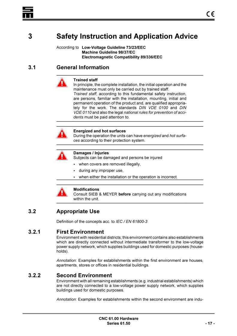
3 Safety Instruction and Application Advice
According to Low-Voltage Guideline 73/23/EEC
Machine Guideline 98/37/EC
Electromagnetic Compatibility 89/336/EEC
3.1 General Information
�Trained staffIn principle, the complete installation, the initial operation and themaintenance must only be carried out by trained staff.Trained staff, according to this fundamental safety instruction,are persons, familiar with the installation, mounting, initial andpermanent operation of the product and, are qualified appropria-tely for the work. The standards DIN VDE 0100 and DIN
VDE 0110 and also the legal national rules for prevention of acci-
dents must be paid attention to.
�Energized and hot surfacesDuring the operation the units can have energized and hot surfa-
ces according to their protection system.
�Damages / InjuriesSubjects can be damaged and persons be injured
< when covers are removed illegally,
< during any improper use,
< when either the installation or the operation is incorrect.
�Modifications
Consult SIEB & MEYER before carrying out any modificationswithin the unit.
3.2 Appropriate Use
Definition of the concepts acc. to IEC / EN 61800-3
3.2.1 First EnvironmentEnvironment with residential districts; this environment contains also establishmentswhich are directly connected without intermediate transformer to the low-voltagepower supply network, which supplies buildings used for domestic purposes (house-holds).
Annotation: Examples for establishments within the first environment are houses,apartments, stores or offices in residential buildings.
3.2.2 Second EnvironmentEnvironment with all remaining establishments (e.g. industrial establishments) whichare not directly connected to a low-voltage power supply network, which suppliesbuildings used for domestic purposes.
Annotation: Examples for establishments within the second environment are indu-
��
CNC 61.00 Hardware
- 18 - Series 61.50
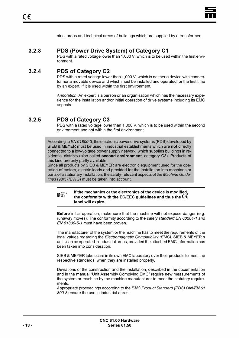
strial areas and technical areas of buildings which are supplied by a transformer.
3.2.3 PDS (Power Drive System) of Category C1PDS with a rated voltage lower than 1,000 V, which is to be used within the first envi-ronment.
3.2.4 PDS of Category C2PDS with a rated voltage lower than 1,000 V, which is neither a device with connec-tor nor a movable device and which must be installed and operated for the first timeby an expert, if it is used within the first environment.
Annotation: An expert is a person or an organisation which has the necessary expe-rience for the installation and/or initial operation of drive systems including its EMCaspects.
3.2.5 PDS of Category C3PDS with a rated voltage lower than 1,000 V, which is to be used within the secondenvironment and not within the first environment.
According to EN 61800-3, the electronic power drive systems (PDS) developed by
SIEB & MEYER must be used in industrial establishments which are not directlyconnected to a low-voltage power supply network, which supplies buildings in re-sidential districts (also called second environment, category C3). Products ofthis kind are only partly available.Since all products by SIEB & MEYER are electronic equipment used for the ope-ration of motors, electric loads and provided for the installation into machines orparts of a stationary installation, the safety-relevant aspects of the Machine Guide-
lines (98/37/EWG) must be taken into account.
LIf the mechanics or the electronics of the device is modified,
the conformity with the EC/EEC guidelines and thus the ��label will expire.
Before initial operation, make sure that the machine will not expose danger (e.g.runaway moves). The conformity according to the safety standard EN 60204-1 and
EN 61800-5-1 must have been proven.
The manufacturer of the system or the machine has to meet the requirements of thelegal values regarding the Electromagnetic Compatibility (EMC). SIEB & MEYER'sunits can be operated in industrial areas, provided the attached EMC information hasbeen taken into consideration.
SIEB & MEYER takes care in its own EMC laboratory over their products to meet therespective standards, when they are installed properly.
Deviations of the construction and the installation, described in the documentationand in the manual “Unit Assembly Complying EMC” require new measurements ofthe system or machine by the machine manufacturer to meet the statutory require-ments.Appropriate proceedings according to the EMC Product Standard (PDS) DIN/EN 61
800-3 ensure the use in industrial areas.

� ��
CNC 61.00 Hardware
Series 61.50 - 19 -
< Products, not equipped with an AC supply line filter must be operated with a se-ries connected mains filter! Detailed information can be found in the chapter "UnitAssembly Complying EMC".
��
CNC 61.00 Hardware
- 20 - Series 61.50
If using the drive systems in residential areas, in business and commercial areas aswell as in small trade, the user has to take additional and larger filter measurements.
SIEB & MEYER products meet the requirements of the Low-Voltage Guideline
73/23/EEC. The coordinated standards of the series IEC / EN 50178 and IEC / EN 60
204-1 in combination with IEC / EN 60 947 and IEC / EN 61800-5-1 are strictly usedfor the products.
Technical data and the connection specification can be found in the respective pro-duct documents.
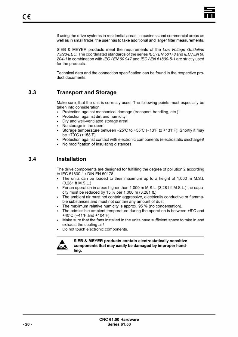
3.3 Transport and Storage
Make sure, that the unit is correctly used. The following points must especially betaken into consideration:< Protection against mechanical damage (transport, handling, etc.)!< Protection against dirt and humidity!< Dry and well-ventilated storage area!< No storage in the open!< Storage temperature between !25/C to +55/C (!13/F to +131/F)! Shortly it may
be +70/C (+158/F).< Protection against contact with electronic components (electrostatic discharge)!< No modification of insulating distances!
3.4 Installation
The drive components are designed for fulfilling the degree of pollution 2 accordingto IEC 61800-1 / DIN EN 50178.< The units can be loaded to their maximum up to a height of 1,000 m M.S.L
(3,281 ft M.S.L.)< For an operation in areas higher than 1,000 m M.S.L. (3,281 ft M.S.L.) the capa-
city must be reduced by 15 % per 1,000 m (3,281 ft.)< The ambient air must not contain aggressive, electrically conductive or flamma-
ble substances and must not contain any amount of dust.< The maximum relative humidity is approx. 95 % (no condensation).< The admissible ambient temperature during the operation is between +5/C and
+40/C (+41/F and +104/F).< Make sure that the fans installed in the units have sufficient space to take in and
exhaust the cooling air!< Do not touch electronic components.
�SIEB & MEYER products contain electrostatically sensitive
components that may easily be damaged by improper hand-
ling.

� ��
CNC 61.00 Hardware
Series 61.50 - 21 -
3.5 Electrical Connection
�The valid rules for prevention of accidents (e.g. VBG 1 and
VBG 4) should be paid attention to, when working at
current-carrying units.
The electrical installation must be carried out according to the relevant electricalcodes (e.g. appropriate wire gauges, fuse protection and connections of ground con-ductors must be considered).
Recommendations for the installation according to the EMC (e.g. shields, connectionto earth and line installations) can be found in the technical documents of the unit(only for machine manufacturers). The manufacturer of the system or machine hasto meet the requirements of the legislation regarding the EMC.
< All work at and within the units must only be carried out, when they are turned offand when the AC line is cut!
< The mains supply must be protected via an overload release with restricted gui-dance for each mains phase.
< The mains line should only be connected, when the work is completed!< Before turning on the unit the first time, make sure that the connected machine
will not have runaway axes!< After turning off the unit hazardous voltages may still exist for up to 3 minutes in
the power supply (due to capacitors).< Capacitive loads must not be connected to the output phases of the servo am-
plifiers and frequency converters.< Prevent cable loops. Therefore, the units must only be connected to earth at the
provided PE connection for the mains supply line and the racks only at the provi-ded earth screw.
Basically, the operation can be made with residual current operated devices. Never-theless, like all clocked units of the power electronics, also SIEB & MEYER's pro-ducts can lead leakage currents via the earth system. Depending on the sensitivityof the residual current operated device and the installation type, the operation alongwith the device may arise problems. The following points should be taken into consi-deration:< Use shortest motor leads possible.< Do not connect additional consumers to the same residual current operated devi-
ce.< Use a residual current operated device with high response threshold.
��
CNC 61.00 Hardware
- 22 - Series 61.50
3.6 Operation
Systems, into which servo amplifiers and frequency converters are mounted, possi-bly must be equipped with additional protective devices according to the valid safetyinstructions (e.g. law about technical material, rules for prevention of accidents,etc.).
All doors and covers must be closed during the operation.
�In order to ensure a trouble-free operation of the installation, thescrews must always be tightened!
3.7 Maintenance
The unit, especially the fan, must be checked regularly for cleanness and functiondepending on the ambient pollution.
3.8 Guarantee
The guarantee is only granted when the points 3.1 to 3.7 are taken into considerati-on.
This Safety Instruction and Application Advice does not assure any features.
�A first programming carried out by SIEB & MEYER does not
release the user from his duty to check programmed values
for their correctness!
SIEB & MEYER AGApril 12, 2006
Save these Safety Instructions!

� Unit Assembly Complying EMC
CNC 61.00 Hardware
Series 61.50 - 23 -
4 Unit Assembly Complying EMC
�The EC guidelines for the electromagnetic compatibility
(EMC) must be taken into consideration for the initial opera-
tion of all SIEB & MEYER units!
The manual "Unit Assembly Complying EMC" is available in German and Englishand comprises
< the EMC guidelines< Information regarding the professional earth and wiring< Safety-relevant aspects< Extracts from the EMC product standard
Availability:< Hard copy version directly from SIEB & MEYER< PDF file in the Internet under www.sieb-meyer.de
5 Automation System CNC 61.00
The CNC 61.00 is a digital controller for high-dynamic servo drives. Synchronousand asynchronous AC servo motors can be driven.
The power and the control components of the CNC 61.00 form a compact unit. Thefields of applications are, among others,< Positioning applications< Variable speed applications< Torque control< Press functions< Nut setting functions< Electronic shafts< Electronic gearbox< Disk cam functions
Along with the drive functions the CNC 61.00 provides PLC functions and the possi-bility to control dialogs via a control terminal.
The CNC 61.00 can be used independently or may be connected with higher-rankingor subordinated controllers (e.g. PLC, industrial PC, etc.). If several CNC 61.00 mo-dules are networked, they can be communicate with each other. Thus, the CNC61.00 can be used for applications dependent on others (e.g. electronic shafts, “fly-ing shears”).
Complex control applications can be executed with the CNC 61.00. The large pro-gram memory enables the programming and execution of extensive processes.
The CNC 61.00 can be supplied as compact unit or rack module.

�Automation System CNC 61.00
CNC 61.00 Hardware
- 24 - Series 61.50
5.1 Hardware Design
The CNC 61.00 combines servo and control functions in one module.
The hardware comprises the following components:< Digital speed and position controllers with a sample rate of 500 :s< Powerful output stages for various motor types and performance ranges< Evaluation of either resolver, Hall effect sensors or optical length measuring sys-
tems< Standard interface with a level according to RS232/485< Eight galvanically separated inputs and outputs< Analog input and output< Additional second measuring system< SIEB & MEYER IO interface
The CNC 61.00 can be expanded by supplementary plug-in modules:< Max. 80 digital inputs and outputs< 10 bit analog/digital converter< 12 bit digital/analog converter< SIEB & MEYER token ring interface< CAN bus interface< INTERBUS interface< PROFIBUS interface< MODLINK interface< Ethernet interface
All components of the hardware can be accessed due to the digitization.
Possible arising errors are indicated as error code via LEDs at the front panel. Eva-luated errors are, among others, overvoltage, undervoltage, tracking error, limitswitch and emergency stop.
5.2 Programming
Executable programs are created with the CNC 61.00 system software on a PC.
Machine functions are programmed in sequential programs, consisting of commandsequences that specify, for example, movement, PLC functions or reaction on userinputs. The CNC 61.00 executes the programmed commands during the run of thesequential program.
The commands have a uniform structure and permit compact programming. Theuser will need only some commands due to the sophisticated command repertoire.

� Automation System CNC 61.00
CNC 61.00 Hardware
Series 61.50 - 25 -
5.3 Performance Features
The following features are worth mentioning for the SIEB & MEYER automation sys-tem CNC 61.00:
Y Direct supply up to 480 VAC
+10 %
Y Single-phase voltage supply for lower motor powers in the version of
325 VDC
Y Galvanic separation between control and power components
Y Extensive protective functions for motor and CNC module (e.g. evalua-
tion of the thermal contact, I2t, etc.)
Y Output for collective fault messages
Y Short-circuit proof (phase to phase, phase to earth)
Y Optimal evaluation of the encoder signals
Y Constant running, even at lowest speeds
Y High dynamics
Y Self-controlled resolver adaptation and adjustment of up to 1,024 angle
pulses (version with resolver evaluation)
Y Phase shifting for an increased drive performance
Y Filter for eliminating possibly arising mechanical resonances (e.g. os-
cillation of coupling)
Y Full operation with cables of up to 100 m length between CNC module
and motor
Y LEDs for diagnostic purposes
Y Space and cost-saving solutions with the compact system
�Automation System CNC 61.00
CNC 61.00 Hardware
- 26 - Series 61.50
19
In
ch
Ch
as
sis
fo
r S
win
g F
ram
e M
ou
nti
ng
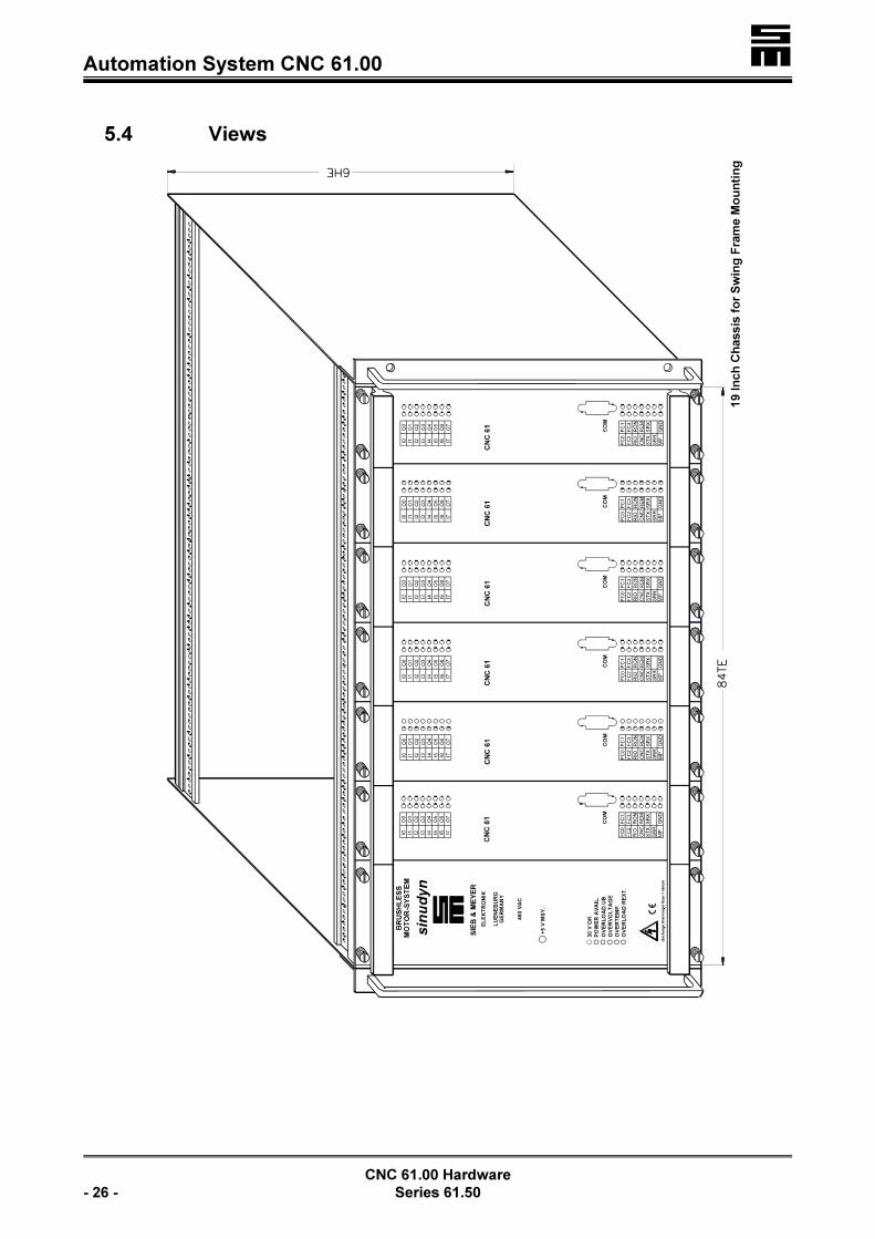
5.4 Views

� Automation System CNC 61.00
CNC 61.00 Hardware
Series 61.50 - 27 -
19
In
ch
Ch
as
sis
fo
r W
all M
ou
nti
ng

�Automation System CNC 61.00
CNC 61.00 Hardware
- 28 - Series 61.50
Compact System for Swing Frame Mounting
� Automation System CNC 61.00
CNC 61.00 Hardware
Series 61.50 - 29 -
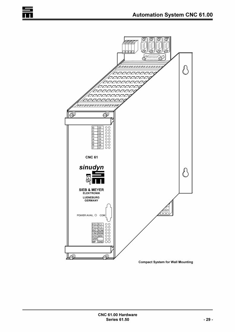
Compact System for Wall Mounting

�Automation System CNC 61.00
CNC 61.00 Hardware
- 30 - Series 61.50

� Mechanical Mounting
CNC 61.00 Hardware
Series 61.50 - 31 -
6 Mechanical Mounting
The power and CNC 61.00 modules for the multi-axis system are mounted into a 19"chassis facilitating the user to easy replace the modules by unscrewing the stopscrews.
The chassis has to be mounted vertically. Customary hinged frames or frames forwall-mounting are valuable for the mounting of the chassis into a switch cabinet.
The modules of the compact system are integrated in a shortened chassis for wall-mounting. They can also easily be replaced by unscrewing the stop screws.
�< Above and below the chassis at least a space of 10 cm must
be provided to ensure sufficient cooling.
< The modules have a very compact design. We recommend
using external fans for the CNC 61.00 modules to achieve a
high life expectancy and an efficiency of 100 % at an ambient
temperature of up to 60°C.
< If the modules are pushed in, it is indispensable to fasten
firmly the stop screws. Otherwise, the secure contact of the
plug-in connectors is not given.
An insecure contact to the back plane can cause damage of
the plug-in connectors.
< The modules must only be replaced, when the lines are de-
ad!
Make sure that the M2.5 fixing screws ensure best connection between back planeand the brass rails in the chassis to form a closed, shielded housing. The leakagecurrents for the interference suppression flow via the fixing screws.
6.1 Replacement of Modules
The modular design of the SIEB & MEYER CNC 61.00 modules facilitates the repla-cement of a complete rack.
When replacing a CNC 61.00 module, pay attention, that the substitute module isadjusted to the same motor (see labeling at the grips). Furthermore, the respectivefirmware (operating system) and application software has to be loaded into the mo-dule (axis). Also pay attention to the correct adjustment for the 24 V supply.
Do not forget to adjust the axis address correctly!

�Mechanical Mounting
CNC 61.00 Hardware
- 32 - Series 61.50
6.2 Mounting of the Back Planes
The back planes have to be fastened with six screws to ensure a good connectionbetween back plane and CNC 61.00 module. Make sure that a reliable connectionbetween back plane and module is given when pushing in the module. An improperconnection can cause a burning of the contacts and, thus, destroy the module.
Connection intermediatecircuit voltage +UB
Clamp connectors for themotor phases W, V, U,
Connection intermediatecircuit voltage !UB
Top fixing:M2.5 × 12
Center fixing:M2.5 × 10
Bottom fixing:M2.5 × 12
LThe grading is made according to the respective rated currents ofthe CNC 61.00 modules, so that the servo module with the lo-west rated current is built in farthest to the power module.

� General Information Regarding the Wiring
CNC 61.00 Hardware
Series 61.50 - 33 -
7 General Information Regarding the Wiring
�The 24 V supply voltages of the connectors X2 to X7 must
only be used to feed encoders, or similar.
Never connect the 24 V lines of the separate axes!
7.1 General Information
The cables, described in this section correspond to the requirements, SIEB & MEY-ER AG demands for a correct function of the cable connections.
If cables are exposed to mechanical strain within the machine, for example in trailingchains or similar, the machine manufacturer must take care for only using appropria-te cables.
In principle, the following points apply for the cables (see also “Unit Assembly Com-plying EMC”, page 23):
< Motor and signal cables must not be wired in the same armored tube!< Motor cables must have a wire-woven shield. They must be wired segregated
from signal lines.< Signal lines must have a wire-woven shield. Difference signals should only be
transmitted in pairwise twisted lines. They must be wired segregated from motorcables.
< The cable shields must be connected to the shell in the connectors. In the switchcabinet they should be connected to an earth bus.
< Cable shields, not ending in a connector within the switch cabinet, such as motorcables, must be connected on the respective bar.
< Both ends of shields are generally to be connected to the shell.
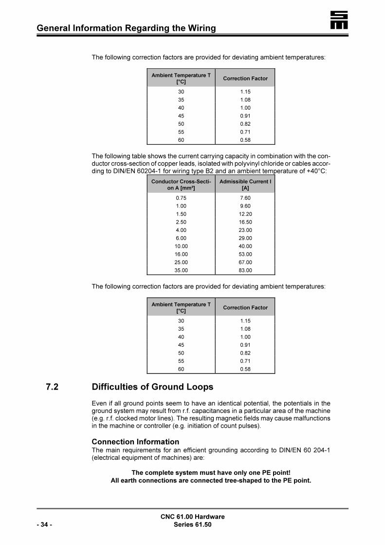
The conductor cross sections should be selected carefully to prevent an exceedingof the maximum admissible current at maximum ambient temperature (the max.ambient temperature of the CNC 61.00 module is 60°C). DIN 60204-1 defines theadmissible values for the separate cross sections, which must absolutely be conside-red.
The following table shows the current carrying capacity in combination with the con-ductor cross-section of copper leads, isolated with polyvinyl chloride or cables accor-ding to DIN/EN 60204-1 for wiring type B2 and an ambient temperature of +40°C:
Conductor Cross-Secti-
on A [mm²]
Admissible Current I
[A]
0.75 7.60
1.00 9.60
1.50 12.20
2.50 16.50
4.00 23.00
6.00 29.00
10.00 40.00
16.00 53.00
25.00 67.00
35.00 83.00
�General Information Regarding the Wiring
CNC 61.00 Hardware
- 34 - Series 61.50
The following correction factors are provided for deviating ambient temperatures:
Ambient Temperature T
[°C]Correction Factor
30 1.15
35 1.08
40 1.00
45 0.91
50 0.82
55 0.71
60 0.58
The following table shows the current carrying capacity in combination with the con-ductor cross-section of copper leads, isolated with polyvinyl chloride or cables accor-ding to DIN/EN 60204-1 for wiring type B2 and an ambient temperature of +40°C:
Conductor Cross-Secti-
on A [mm²]
Admissible Current I
[A]
0.75 7.60
1.00 9.60
1.50 12.20
2.50 16.50
4.00 23.00
6.00 29.00
10.00 40.00
16.00 53.00
25.00 67.00
35.00 83.00
The following correction factors are provided for deviating ambient temperatures:
Ambient Temperature T
[°C]Correction Factor
30 1.15
35 1.08
40 1.00
45 0.91
50 0.82
55 0.71
60 0.58
7.2 Difficulties of Ground Loops
Even if all ground points seem to have an identical potential, the potentials in theground system may result from r.f. capacitances in a particular area of the machine(e.g. r.f. clocked motor lines). The resulting magnetic fields may cause malfunctionsin the machine or controller (e.g. initiation of count pulses).
Connection InformationThe main requirements for an efficient grounding according to DIN/EN 60 204-1(electrical equipment of machines) are:
The complete system must have only one PE point!
All earth connections are connected tree-shaped to the PE point.

� General Information Regarding the Wiring
CNC 61.00 Hardware
Series 61.50 - 35 -
Connecting example of a machine and the connected
CNC with connection to earth according to the EMC
guidance
Particular notes:< The PE point usually is the connecting
point of the PE conductor of the voltagesupply or the earth connection of a sepa-rate earth arrangement of the completesystem.
< If several points within the system aremarked with PE, all marks should be
provided with the earth character �,except for one.
< Motors must be connected with least
impedance to the earth points �. Earthconnections to the outputs of the servoamplifiers must not be made!
< Motors, mounted on an insulated ma-chine part (e.g. linear motors, handheldnut setting unit, etc.) must be connectedto earth with largest surface.
< Earth connections must always be made with largest surface. Earth straps, consi-sting of many thin wires offer a larger surface than only one fixed core with thickcross-section. Earth connectors should be shortest possible.
7.3 Motor Cables
Use shielded conductors for the motor to ensure as low as possible interferences(conductor cross section according to table). The shield must be put with both endsto the PE.

�General Information Regarding the Wiring
CNC 61.00 Hardware
- 36 - Series 61.50
7.4 Cables for the First Measuring System
Use shielded conductors and shielded Submin D shells for the wiring of the differentmeasuring systems. At the side of the CNC 61.00 module the shield must be put withone end to the Submin D shell and at the side of the measuring system on its hou-sing.
Examples for the usage of conductors:
< Motors with resolverLIYCY 3 × 2 × 0.14 or 4 × 2 × 0.14 for motors with integrated thermal contact.Shielded, pairwise twisted conductors. Twist mode: sine/sine, cosine/cosine, ro-tor/rotor and, if necessary, thermal contact/thermal contact.We recommend to additionally shield the separate pairs for delicate applications.
< Motors with incremental encoderLIYCY 5 × 0.14 or 7 × 0.14 for motors with integrated thermal contact.
< Motors with Hall effect sensors and tacho generatorLIYCY 9 × 0.14 or 12 × 0.14 for motors with integrated thermal contact.
7.5 Cables for the Second Measuring System
Use shielded conductors with a shielded Submin D shell, like for example LIYCY4 × 0.14, for the wiring of the Second Measuring System. At the side of the CNC61.00 module the shield must be put with one end to the Submin D shell and at theside of the second measuring system on its housing.
We recommend using pairwise twisted conductors, possibly with an additional shieldof the separate pairs for delicate applications. Twist mode: A+/A!; B+/B!.
LAs at all fast-clocked devices of the power electronics also theCNC 61.00 module can deliver high-frequency perturbing radiati-on into the feeding mains and leakage current can occur.Specific measures in the circuitry of the devices already providean effective protection against possible interferences (high fre-quency screening unit). However, due to the integration of themodules into plants with their resulting physical operating para-meters the admissible values according to VDE 0875 can be ex-ceeded. Therefore, the user should take additional steps, if ne-cessary. Interferences can considerably be reduced with specifictransformers or filter sections and by appropriate wiring.

� General Information Regarding the Wiring
CNC 61.00 Hardware
Series 61.50 - 37 -
7.6
Cables for the Connection of the I/O Expansion Modules
Use a shielded conductor with shielded Submin D shell, like for example LIYCY 4 ×2 × 0.14, for the wiring of the I/O Expansion Modules. Put the shield on the SubminD shell at the side of the CNC 61.00 module.
We recommend using pairwise twisted conductors, possibly with an additional shieldof the separate pairs for delicate applications.
7.7 Cables for the Terminal Connections
Use a shielded conductor with shielded Submin D shell, like for example LIYCY 4 ×0.14, for the wiring of the Terminal Connections. Put the shields on the Submin Dshell at the sides of the CNC 61.00 module and the PC.
7.8 Cables for the INTERBUS
If malfunctions arise during the bus operation, conducting the shield of the INTER-BUS with one side via a 47 nF capacitor to earth can be useful.
Otherwise the points, described in the section “General Information”, see page 33,apply for the INTERBUS.
7.9 Cables for the External Ballast Resistor
The lines to the external ballast resistor from REX
and +UB should be twisted. A shiel-ded cable must be used, if the lines is longer than 20 cm.

�General Information Regarding the Wiring
CNC 61.00 Hardware
- 38 - Series 61.50
7.10 Wiring of the 24 V (Internal/External)
For the back planes of the multi-axis system applies:Supply of 24 V to connector 23: external 24 VStrap between connectors 22 and 23: internal 24 V
For the back planes of the compact system applies:Open hook switch S1: external 24 VClosed hook switch S1: internal 24 V
LThe total load of all outputs must not exceed 350 mA. Each out-put can be loaded with max. 100 mA..
� Connection Diagrams
CNC 61.00 Hardware
Series 61.50 - 39 -
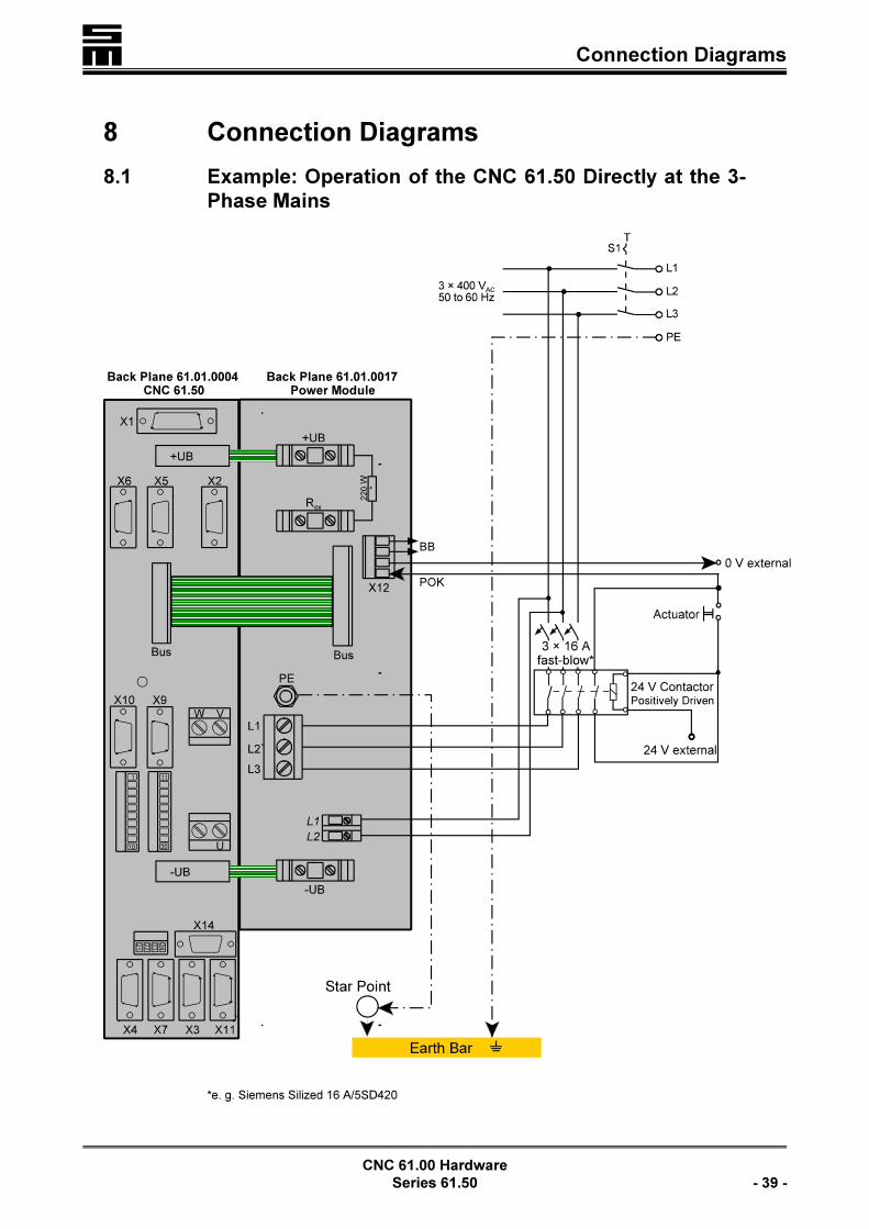
8 Connection Diagrams
8.1 Example: Operation of the CNC 61.50 Directly at the 3-
Phase Mains
*e. g. Siemens Silized 16 A/5SD420

�Connection Diagrams
CNC 61.00 Hardware
- 40 - Series 61.50
8.2 Example: Compact System 3-Phase Supply with Auto-
transformer

� Connection Diagrams
CNC 61.00 Hardware
Series 61.50 - 41 -
8.3 Example: Compact System With 1-Phase Supply

�Connection Diagrams
CNC 61.00 Hardware
- 42 - Series 61.50

� Front Panels
CNC 61.00 Hardware
Series 61.50 - 43 -
9 Front Panels
9.1 Front Panel of the Multi-Axis System
I0 O0
Status indication of the inputs/outputs of the connector “1 to20 - Logic Signals” (page 63)
I1 O1
I2 O2
I3 O3
I4 O4
I5 O5
I6 O6
I7 O7
COM Connection of the terminal/programming unit (page 55)
FC0 FC1Status indication/error messages (starting on page 46)
FC2 FC3
RIO RON Indication of malfunctions / of the controller (page 53)
CNC REM Indication of operation / “remote control” (page 53)
STX SRX Status indication/error messages of bus systems (1 LEDwithout designation, page 54)SRR
MP GND Test pin
�Front Panels
CNC 61.00 Hardware
- 44 - Series 61.50
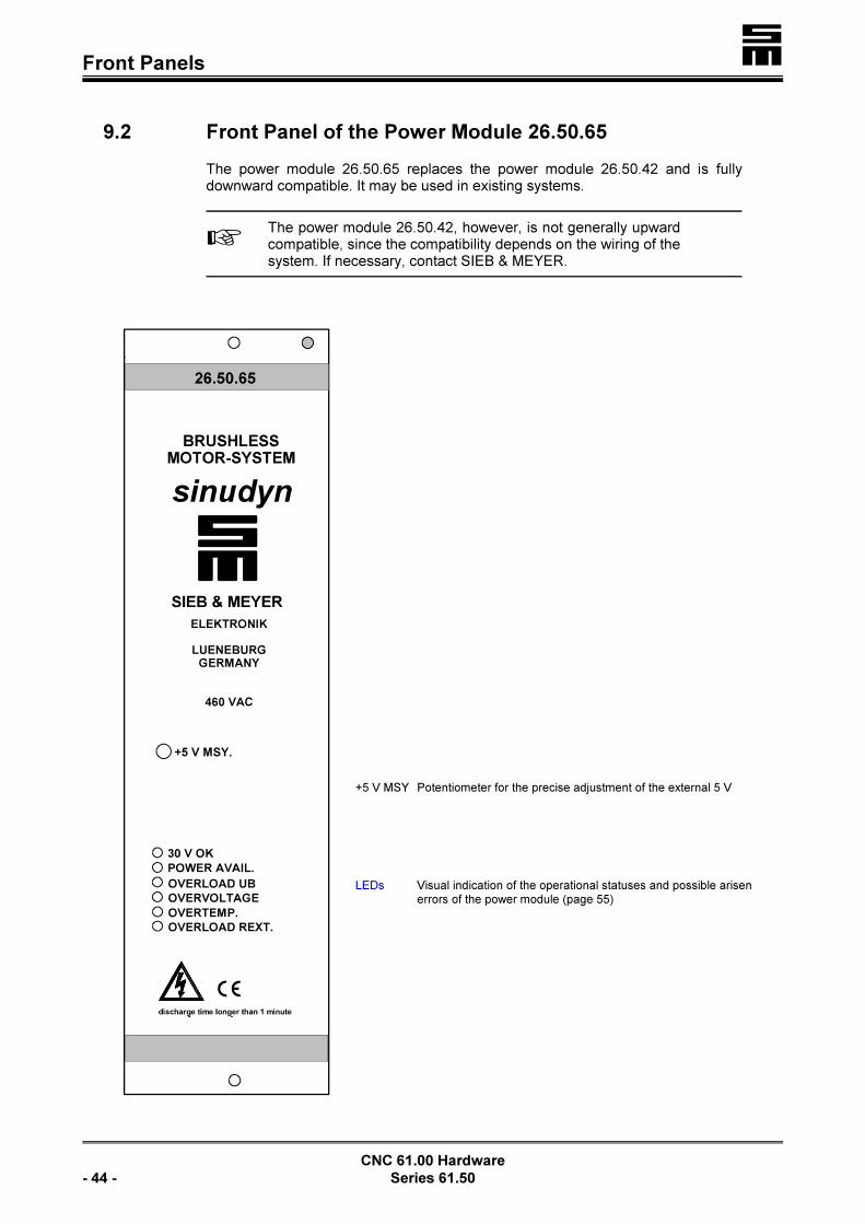
9.2 Front Panel of the Power Module 26.50.65
The power module 26.50.65 replaces the power module 26.50.42 and is fullydownward compatible. It may be used in existing systems.
LThe power module 26.50.42, however, is not generally upwardcompatible, since the compatibility depends on the wiring of thesystem. If necessary, contact SIEB & MEYER.
+5 V MSY Potentiometer for the precise adjustment of the external 5 V
LEDs Visual indication of the operational statuses and possible arisenerrors of the power module (page 55)

� Front Panels
CNC 61.00 Hardware
Series 61.50 - 45 -
9.3 Front Panel of the Compact System
I0 O0
Status indication of the inputs/outputs of connec-tor “1 to 20 - Logic Signals” (page 63)
I1 O1
I2 O2
I3 O3
I4 O4
I5 O5
I6 O6
I7 O7
POWER AVAIL. Status of the integrated power module
COM Connection of terminal/programming unit (page 55)
FC0 FC1 Status indication/error messages (starting onpage 46)FC2 FC3
RIO RONIndication of malfunctions / of the controller (pa-ge 53)
CNC REMIndication of operation / “remote control” (page53)
STX SRX Status indication/error messages of bus sys-tems (1 LED without designation, page 54)SRR
MP GND Test pin

�Front Panels
CNC 61.00 Hardware
- 46 - Series 61.50
9.4 Indications / Connections of the CNC 61.50 Front Panels
9.4.1 Status Indication FC0 to FC3 (Red Flashing)
FC0 FC1
FC2 FC3
LED is continuously on (red): permanent error, e. g. emergency stopLED is flashing red: error occurred and must be reset with the software
LEDs Code* Error Reaction Possible Cause LEDs**
����
0 no error no����
����
129active monitoring
of travel arearef. position = actual positionref. speed = zero
����
����
130 14 V not providedref. speed = zero and regulator off1
����
����
131 !14 V not providedref. speed = zero and regulator off1
����
����
132 short circuitref. speed = zero and regulator off1
double peak current flows via themeasuring shunt into the outputstage
����
����
133 reserved no����
����
134overvoltage/undervoltage
ref. speed = zero and regulator off1,2
Overvoltage:325 VDC method = switch-off thres-hold 385 V560 VDC method = switch-off thres-hold 810 VUndervoltage: Voltage < 42 V24 V not provided24 V internal:
fuse has responded24 V external:
24 V not provided
����
����
135error of first
measuring systemref. speed = zero and regulator off1
����
����
136 motor temperatureref. speed = zero and regulator off1
ETC/PTC- characteristic adjustab-le. Check the adjustment.
����
����
137 heat sink temperatureref. speed = zero and regulator off1
heat sink is too hot����
����
138 I²t-computerref. speed = zero and regulator off1
The rated current has been excee-ded, or the motor became to hot.
����
����
140 emergency stopDeceleration with the parameter“Quick Delay”
����
����
141 positive limit switchref. position = actual positionref. speed = zero
����
����
142 negative limit switchref. position = actual positionref. speed = zero
����
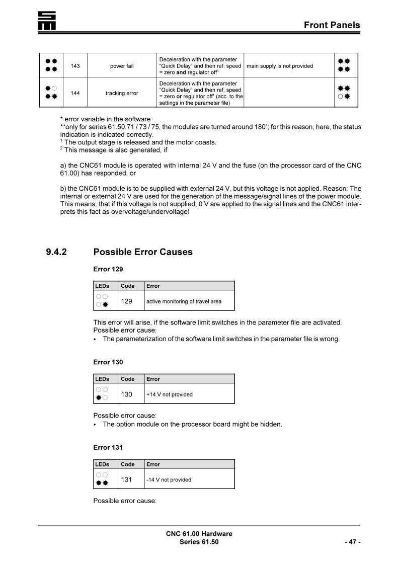
� Front Panels
CNC 61.00 Hardware
Series 61.50 - 47 -
����
143 power failDeceleration with the parameter“Quick Delay” and then ref. speed= zero and regulator off1
main supply is not provided����
����
144 tracking error
Deceleration with the parameter“Quick Delay” and then ref. speed= zero or regulator off1 (acc. to thesettings in the parameter file)
����
* error variable in the software **only for series 61.50.71 / 73 / 75, the modules are turned around 180/; for this reason, here, the statusindication is indicated correctly.1 The output stage is released and the motor coasts.2 This message is also generated, if
a) the CNC61 module is operated with internal 24 V and the fuse (on the processor card of the CNC61.00) has responded, or
b) the CNC61 module is to be supplied with external 24 V, but this voltage is not applied. Reason: Theinternal or external 24 V are used for the generation of the message/signal lines of the power module.This means, that if this voltage is not supplied, 0 V are applied to the signal lines and the CNC61 inter-prets this fact as overvoltage/undervoltage!
9.4.2 Possible Error Causes
Error 129
LEDs Code Error
����
129 active monitoring of travel area
This error will arise, if the software limit switches in the parameter file are activated.Possible error cause:
< The parameterization of the software limit switches in the parameter file is wrong.
Error 130
LEDs Code Error
����
130 +14 V not provided
Possible error cause:
< The option module on the processor board might be hidden.
Error 131
LEDs Code Error
����
131 -14 V not provided
Possible error cause:

�Front Panels
CNC 61.00 Hardware
- 48 - Series 61.50
< The option module on the processor board might be hidden.
Error 132
LEDs Code Error
����
132 short circuit
Possible error cause:
< error in the wiring of the motor cable
< broken or squeezed motor cable (especially trailing chain)
< if the motor cables have been pulled off the back plane, the output stage of theCNC61 will be defective
Error 134
LEDs Code Error
����
134 overvoltage/undervoltage
Possible error cause, if undervoltage:
< external 24 V supply is faulty
< 24 V fuse on the CNC61 (processor card) is defective
< the main voltage supply of the power module is faulty (too low)
Possible error cause, if overvoltage:
< external 24 V supply is faulty
< 24 V fuse on the CNC61 (processor card) is defective
< the main voltage supply of the power module is faulty (too low)
< wrong connection of the ballast resistor
< the braking power of the power module has been exceeded
Error 135
LEDs Code Error
����
135 error of the first measuring system
Possible error cause:
< broken or squeezed cable of the measuring system(especially trailing chain)
< the connector of the first measuring system (X1) is not connected or wrongly con-nected
< error in the wiring of connector X1 at the back plane or in the wiring of the resol-ver connector at the motor
Error 136
LEDs Code Error
����
136 motor temperature
Possible error cause:

� Front Panels
CNC 61.00 Hardware
Series 61.50 - 49 -
< the motor became too hot due to overload
< wrong connection of the PTC (NTC)
< the connection between the CNC61 and the PTC has been interruptedError 137
LEDs Code Error
����
137 heat sink temperature
Possible error cause:
< the ambient temperature of the CNC61 is too hot (in the switch cabinet)
Error 138
LEDs Code Error
����
138 l²t-load
Possible error cause:
< the machine became mechanically sluggish
< the parameter values of the traveling speed/acceleration are too high
< error in the wiring of the motor phases
Error 140
LEDs Code Error
����
140 emergency stop
Possible error cause:
< emergency stop is initiated
< wrong wiring of input 0 of the CNC61
Error 141
LEDs Code Error
����
141 positive limit switch
Possible error cause:
< the machine is on the limit switch
< the limit switch or the wiring is defective
< wrong wiring of input 1 of the CNC61
Error 142
LEDs Code Error
����
142 negative limit switch
Possible error cause:

�Front Panels
CNC 61.00 Hardware
- 50 - Series 61.50
< the machine is on the limit switch
< the limit switch or the wiring is defective
< wrong wiring of input 2 of the CNC61
Error 143
LEDs Code Error
����
143 power fail
a) The LED "Power Avail." of the power module is on.
Possible error cause:
< the 24 V fuse of the CNC61 (processor card) is defective
< the external 24 V supply is faulty
b) The LED "Power Avail." of the power module is off.
Possible error cause:
< emergency stop has been initiated
< the main voltage supply of the power module is not provided
Error 144
LEDs Code Error
����
144 tracking error
Possible error cause:
< the machine became mechanically sluggish
< error in the wiring of the motor phases
< the acceleration or the delay of the motor is too high
Error: The LEDs of all CNCs are off.
a) The LED "30V OK" of the power module is on.
Possible error cause:
< fuse F1 of the power module is defective
b) The LED "30V OK" of the power module is off.
Possible error cause:
< the logic voltage supply of the power module is faulty
< fuses F2 and F3 of the power module are defective

� Front Panels
CNC 61.00 Hardware
Series 61.50 - 51 -
Card of the Power Module 26.50.0038.xx/26.50.0073.xx
C / K H / I
F1 6.3 A 6.3 A 5 x 20 mm semi time-lag
F2 3.15 A 2 A 6.3 x 32 mm fast-blow (500 V)
F3 3.15 A 2 A 6.3 x 32 mm fast-blow (500 V)

�Front Panels
CNC 61.00 Hardware
- 52 - Series 61.50
Processor Card 26.44.0041.xx
F1 5x20 500mA semi time-lag

� Front Panels
CNC 61.00 Hardware
Series 61.50 - 53 -
9.4.3 Status Indication FC0 to FC3 (Green and Red)
FC0 FC1
FC2 FC3
LEDs Status Cause
� �� �
FC0 lights green PI LIMIT and Regulator ON are active
� �� � FC0 to FC3 alternately light red
and greenno operating system (firmware) is provided
� �� �
9.4.4 RIO - Malfunction Indication
RIO Meaning
� no error of regulator
� error of regulator
9.4.5 RON- Status of Regulator
RON Meaning
� regulator ON
� regulator OFF
9.4.6 CNC - Operation Indication
CNC Meaning
� CNC operation
� REMOTE operation
9.4.7 REM - Indication “Remote Control”
REM Meaning
� CNC operation
� REMOTE operation

�Front Panels
CNC 61.00 Hardware
- 54 - Series 61.50
9.4.8 STX / SRX / SRR - Status Indication/ Error Messages of
Bus Systems
Bus System MODLINK (Accessory Module F1)
LED Meaning
STX green� transmission signal is provided
� no transmission signal
SRX green� receive signal is provided
� no receive signal
SRR red/orange� transmission failure
� no fault
* red/orange�
without meaning�
* LED has no designation
Bus System INTERBUS-S (Accessory Module A1)
LED Meaning
STX green� bus connection is completed
� no bus connection
SRX green� monitoring of the input remote
bus cable
� no monitoring
SRR red/orange�
no meaning�
* red/orange� module fault/inactive master
� no fault
* LED has no designation
Bus System INTERBUS (A1) and MODLINK (F1)
LED Meaning
STX green� transmission signal is provided
� no transmission signal
SRX green� receive signal is provided
� no receive signal
SRR red/orange� transmission failure
� no fault
* red/orange� module fault / no active master
in the INTERBUS�
* LED has no designation

� Front Panels
CNC 61.00 Hardware
Series 61.50 - 55 -
Bus System Profibus-DP (Accessory Modules AB, AE and AF)
LED Meaning
STX green�
no meaning
�
SRX green�
�
SRR red/orange�
�
* red/orange� communication is OK
� faulty communication
* LED has no designation
9.4.9 COM - Connection of Terminal/Programming Unit
9-pole female Submin D connector, corresponding with its levels to the RS 232 charac-teristics.
not to be wired 16 not to be wired
TxD 27 CTS
RxD 38 RTS
5 V 49 not to be wired
GND 5
9.5 LEDs of the Power Module 26.50.65x
LED Meaning
30 V OK green � logic supply L1 and L2 is OK
POWER AVAIL. green � generation of the intermediate circuit voltage L1, L2 and L3 is OK
OVERLOAD UB red � short within the intermediate circuit
OVERVOLTAGE red� overvoltage in the intermediate circuit
� the I2t monitoring of the ballast circuit has responded
OVERTEMP. red � the monitoring of excess temperature has responded
OVERLOAD red � short circuit at the external ballast resistor
� LED is on
� LED flashes

�Front Panels
CNC 61.00 Hardware
- 56 - Series 61.50

� Back Plane 61.01.0004
CNC 61.00 Hardware
Series 61.50 - 57 -
10 Back Planes and Pin Assignment
10.1 Back Planes for the Multi-Axis System
10.1.1 Back Plane 61.01.0004 for INTERBUS, MODLINK and CAN
Bus
Mounting into a 19” rack as hinged-frame unit and protection against touching
X1 Connection of the first measuring system, page 58
+UB Intermediate circuit voltage
X6 INTERBUS connection (outputs), page 61
X5 INTERBUS connection (inputs), page 60
X2 Terminal connection, page 59
Bus Internal connection, page 64
X10 MODLINK connection (inputs), page 62
X9 MODLINK connection (outputs), page 61
V W Motor connection, page 64
1 to 20 Logic signals, page 63
U Motor connection, page 64
!UB Intermediate circuit voltage
21 to 24 Thermal contact/ 24 V external, page 63
X14 Transducer/analog input, page 62
X4 Angle pulse connection, page 60
X7 Angle pulse connection, page 61
X3 I/O expansion, page 59
X11 CAN bus connection, page 62

�Back Plane 61.01.0004
CNC 61.00 Hardware
- 58 - Series 61.50
X1 - Connection of First Measuring System (Feedback)
15-pole female Submin D connector
Resolver Evaluation
0 V (shield) =! 19 =! S3 sine
S1 sine !< 210 !< 0 V
0 V =! 311 =! S2 cosine
S4 cosine !< 412 !< 0 V
0 V =! 513 !< R1 rotor
R3 rotor =! 614 !< 0 V
thermal contact* !< 715 !< +24 V (thermal contact*)
0 V =! 8
< If the thermal contact (*) is not evaluated, the Pins 15 and 7 must be strapped.< Use a shielded cable with three pairs of wires, each of which being twisted (e.
g. LIYCY 3 × 2 × 0.14). Twist mode: sine/sine; cosine/cosine; rotor/rotor.< The shield must be connected with both ends: At the CNC on the connector
shell and at the resolver, as described in the chapter “Wiring”, “General Infor-mation”, page 33.
Hall Effect Sensor Evaluation
0 V =! 19 =! sensor C
sensor A !< 210 =! sensor B
not to be wired 311 not to be wired
not to be wired 412 not to be wired
not to be wired 513 !< +14 V
free 614 !< GND
thermal contact* !< 715 !< thermal contact*
GND =! 8
< If no thermal contact (*) is connected, Pin 7 and Pin 15 must be strapped.< Use a shielded cable. Connect the shield with largest surface to the connector
shell.

� Back Plane 61.01.0004
CNC 61.00 Hardware
Series 61.50 - 59 -
Optical Length Measuring System
0 V =! 19 =! 0°
0° !< 210 !< 0 V
0 V =! 311 =! 90°
90° !< 412 !< 0 V
0 V =! 513 !< ref.+
ref.– =! 614 !< 0 V
thermal contact* !< 715 !< thermal contact*
+5 V =! 8
< If no thermal contact (*) is connected, Pin 7 and Pin 15 must be strapped.< Use a shielded cable with four pairs of wires, each of which being twisted.
Twist mode: /0°, /90°, ref.+/ref.– and +5 V/0 V. If the thermal contact is0° 90°evaluated, a shielded twisted pair cable with five pairs of wires must be used.
< For incremental encoders without difference voltage signal the Pins 9 and 11must be supplied with 5 V (Pin 8).
< Connect the shield with largest surface to the connector shell.
X2 - Terminal Connection
9-pole female Submin D connector with levels corresponding to the RS232 and RS485specifications.
D! (RS 485) 16 D+ (RS 485)
TxD 27 CTS
RxD 38 RTS
24 V 49 0 V
GND 5
X3 - I/O Expansion
9-pole female Submin D connector
DO! 16 DO+
CLK! 27 CLK+
LD! 38 LD+
DI! 49 DI+
0 V 5

�Back Plane 61.01.0004
CNC 61.00 Hardware
- 60 - Series 61.50
X4 - Angle Pulses
9-pole female Submin D connector
The connectors are either inputs or outputs.Inputs: 5 V or 24 VOutputs: 5 V
Accessory Modules AG, AH
BA, B1/B2, B4, B5, B9 and C2/C3
Angle Pulse Input
UA0+ 16 UB0+
UA0! 27 UB0!
zero pulse UN0+ 38 24 V output
zero pulse UN0! 49 0 V
GND 5
Accessory Modules B3 and C4
Angle Pulse Output
UA0+ 16 UB0+
UA0! 27 UB0!
not assigned 38 24 V
not assigned 49 0 V
GND 5
Accessory Module B7/B8
Counter Input
counter input 16 count direction*
connect to 0 V 27 connect to 0 V
not to be wired 38 24 V output
not to be wired 49 0 V
GND 5
* not wired: positive count direction5 V/24 V: negative count direction
Accessory Modules A5 and A6
Serial Interface 2
not to be wired 16 RTS
TxD 27 CTS
RxD 38 not to be wired
not to be wired 49 not to be wired
GND 5
X5 - INTERBUS-S Connection
9-pole female Submin D connector
DO 2+ 16 DO 2!
DI 2+ 27 DI 2!
GND 38
49 RBST
5 V 5

� Back Plane 61.01.0004
CNC 61.00 Hardware
Series 61.50 - 61 -
X6 - INTERBUS-S Connection
9-pole male Submin D connector
DO 1+ 16 DO 1!
DI 1+ 27 DI 1!
GND 38
49
5
X7 - Angle Pulses
9-pole female Submin D connector
Accessory Modules
BA, B4, B7/B8
Angle Pulse Output
UA0+ 16 UB0+
UA0! 27 UB0!
free 38 24 V
free 49 0 V
0 V 5
Accessory Modules B5 and B9
Angle Pulse Input
UA0+ 16 UB0+
UA0! 27 UB0!
zero pulse UN0+ 38 24 V
zero pulse UN0! 49 0 V
0 V 5
Accessory Modules
C2/C3 and C4
SSI Interface
SSI clock+ 16 SSI data+
SSI clock! 27 SSI data!
free 38 24 V
free 49 0 V
0 V 5
X9 - MODLINK Connection
9-pole female Submin D connector
DO+ 16
DO! 27
38
GND 49
5

�Back Plane 61.01.0004
CNC 61.00 Hardware
- 62 - Series 61.50
X10 - MODLINK Connection
9-pole male Submin D connector
DI+ 16
DI! 27
38
GND 49
5
X11 - CAN Bus Connection
9-pole female Submin D connector
16
CAN-L 27 CAN-H
GND 38
49 VCCCAN
5
VCCCAN: 8 V to 15 V
X14 - Transducer/Analog Input
9-pole female Submin D connector
Accessory Modules A3, A5, AA and AE
Transducer Input
analog input - 16 analog input +
27
output voltage +5 V 38 output voltage !5 V
49 GND
5
Accessory Modules A4 and A6
Analog Input
analog input + 16 analog input !
27
38 GND
49 GND
5
Accessory Module AF
Active Transducer
analog input (±5 V) 16 calibrating signal
27
supply voltage +12 V 38 supply voltage !12 V
49 GND (shared ground)
5

� Back Plane 61.01.0004
CNC 61.00 Hardware
Series 61.50 - 63 -
1 to 20 - Logic Signals
PHOENIX Mini CombiCon
All inputs and outputs work with a level of 24 V. The total load of all outputs must notexceed 350 mA.
Please take into consideration that some inputs and outputs have alternating mea-ning. If, for example, the function “Motor Brake” has been activated in the parametereditor (IP_E_BRAKE=ON), the output o1 will automatically be identical with thefunction “Motor Brake”.
1 regulator OK+(voltage-free contacts)
2 regulator OK
3 output o0 (always regulator OK)
4 output o2
5 output o1 (= motor brake, if IP_E_BRAKE = ON)
6 output o7
7 output o6
8 output o5
9 output o4
10 output o3
11 input i2 (= limit switch–, if IP_E_END = ON)
12 input i1 (= limit switch+, if IP_E_END = ON)
13 input i3
14 input i0 (always emergency stop)
15 input i7
16 input i6
17 input i5
18 input i4
19 0 V*
20 24 V*
* see also the section “Wiring of the 24 V (Internal/External) in the chapter“Wiring”, page 38.
< Additional inputs and outputs can be connected to X3 via the I/O modules44.20.xxx. See also the chapter “External I/O Modules”, starting on page201.
21 to 24 - Thermal Contact/24 V External
PHOENIX Mini CombiCon
21 thermal contact
22 24 V internal
23 24 V external
24 0 V
Wiring of the 24 V (Internal/External), see chapter “Wiring”, section “Wiring of 24 V(internal/external)”, page 38.

�Back Plane 61.01.0004
CNC 61.00 Hardware
- 64 - Series 61.50
U / V / W - Motor Connections
< WEIDMÜLLER screw connectorsThe maximum conductor cross-section for the terminals is 10 mm².
Bus - Internal Connection
The 10-pole bus line connects the power module and up to six CNC rack modules.The bus supplies the CNC modules with the voltage of +30 V (bus voltage). Addi-tionally, statuses of the power module (readiness for operation, malfunctions) aresignaled to the CNC 61.00 modules. At the power module the bus pins are outputs,whereas at the CNC module the bus pins are inputs.
Pin Assignment
1 + 2 ground potential
3 mains OK = +24 V
4overvoltage message:
0 V in case of an error24 V without error
5 +24 V
6 not assigned
7 + 8 +30 V � mains potential
9 + 10 0 V for the 30 V � mains potential
�Do not use the +30 V for any other purposes!
Mains OKThis output intra-system activates and deactivates, inter alia, the CNC modules. Ifthe main supply is not provided, the signal “mains OK” will be LOW and the CNCmodules cannot be activated. The user may use this signal via the contacts BB.
Overvoltage MessageIf an overvoltage comes up, the level of 24 V bounces to 0 V. Then the regulator inthe CNC module is deactivated (POK and the main contactor open). Error messages,however, are kept.
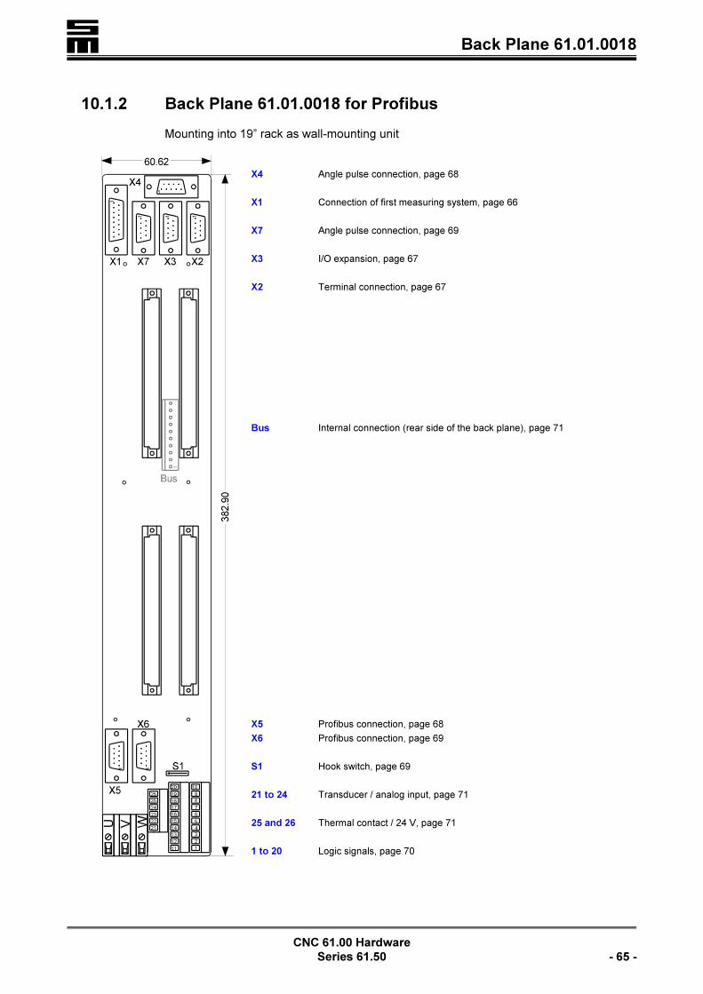
� Back Plane 61.01.0018
CNC 61.00 Hardware
Series 61.50 - 65 -
10.1.2 Back Plane 61.01.0018 for Profibus
Mounting into 19” rack as wall-mounting unit
X4 Angle pulse connection, page 68
X1 Connection of first measuring system, page 66
X7 Angle pulse connection, page 69
X3 I/O expansion, page 67
X2 Terminal connection, page 67
Bus Internal connection (rear side of the back plane), page 71
X5 Profibus connection, page 68
X6 Profibus connection, page 69
S1 Hook switch, page 69
21 to 24 Transducer / analog input, page 71
25 and 26 Thermal contact / 24 V, page 71
1 to 20 Logic signals, page 70

�Back Plane 61.01.0018
CNC 61.00 Hardware
- 66 - Series 61.50
X1 - Connection of First Measuring System (Feedback)
15-pole female Submin D connector
Resolver Evaluation
0 V (shield) =! 19 =! S3 sine
S1 sine !< 210 !< 0 V
0 V =! 311 =! S2 cosine
S4 cosine !< 412 !< 0 V
0 V =! 513 !< R1 rotor
R3 rotor =! 614 !< 0 V
thermal contact* !< 715 !< +24 V (thermal contact*)
0 V =! 8
< If the thermal contact (*) is not evaluated, the Pins 15 and 7 must be strap-ped.
< Use a shielded cable with three pairs of wires, each of which being twisted(e.g. LIYCY 3 × 2 × 0.14). Twist mode: sine/sine; cosine/cosine; rotor/rotor
< The shield must be connected with both ends: At the CNC on the connectorshell and at the resolver, as described in the chapter “Wiring”, “General Infor-mation”, page 33.
Hall Effect Sensor Evaluation
0 V =! 19 =! sensor C
sensor A !< 210 =! sensor B
not to be wired 311 not to be wired
not to be wired 412 not to be wired
not to be wired 513 !< +14 V
free 614 !< GND
thermal contact* !< 715 !< thermal contact*
GND =! 8
< If no thermal contact (*) is connected, Pin 7 and Pin 15 must be strapped.< Use a shielded cable. Connect the shield with largest surface to the connec-
tor shell.
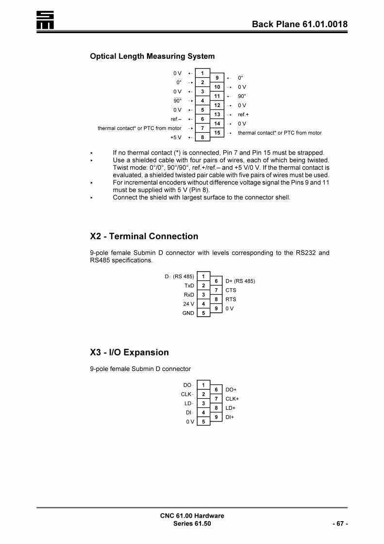
� Back Plane 61.01.0018
CNC 61.00 Hardware
Series 61.50 - 67 -
Optical Length Measuring System
0 V =! 19 =! 0°
0° !< 210 !< 0 V
0 V =! 311 =! 90°
90° !< 412 !< 0 V
0 V =! 513 !< ref.+
ref.– =! 614 !< 0 V
thermal contact* or PTC from motor !< 715 !< thermal contact* or PTC from motor
+5 V =! 8
< If no thermal contact (*) is connected, Pin 7 and Pin 15 must be strapped.< Use a shielded cable with four pairs of wires, each of which being twisted.
Twist mode: /0°, /90°, ref.+/ref.– and +5 V/0 V. If the thermal contact is0° 90°evaluated, a shielded twisted pair cable with five pairs of wires must be used.
< For incremental encoders without difference voltage signal the Pins 9 and 11must be supplied with 5 V (Pin 8).
< Connect the shield with largest surface to the connector shell.
X2 - Terminal Connection
9-pole female Submin D connector with levels corresponding to the RS232 andRS485 specifications.
D! (RS 485) 16 D+ (RS 485)
TxD 27 CTS
RxD 38 RTS
24 V 49 0 V
GND 5
X3 - I/O Expansion
9-pole female Submin D connector
DO! 16 DO+
CLK! 27 CLK+
LD! 38 LD+
DI! 49 DI+
0 V 5

�Back Plane 61.01.0018
CNC 61.00 Hardware
- 68 - Series 61.50
X4 - Angle Pulses
9-pole female Submin D connector
The connectors are either inputs or outputs.Inputs: 5 V or 24 VOutputs: 5 V
Accessory Modules AG, AH
BA, B1/B2, B4, B5, B9 and C2/C3
Angle Pulse Input
UA0+ 16 UB0+
UA0! 27 UB0!
zero pulse UN0+ 38 24 V output
zero pulse UN0! 49 0 V
GND 5
Accessory Modules B3 and C4
Angle Pulse Output
UA0+ 16 UB0+
UA0! 27 UB0!
not assigned 38 24 V
not assigned 49 0 V
GND 5
Accessory Module B7/B8
Counter Input
counter input 16 count direction*
connect to 0 V 27 connect to 0 V
not to be wired 38 24 V output
not to be wired 49 0 V
GND 5
* not wired: positive count direction5 V/24 V: negative count direction
Accessory Modules A5 and A6
Serial Interface 2
not to be wired 16 RTS
TxD 27 CTS
RxD 38 not to be wired
not to be wired 49 not to be wired
GND 5
X5 - Profibus-DP Connection
9-pole female Submin D connector
shield 16 VP
27
RxD/TxD-P 38 RxD/TxD-N
49
DGND 5

� Back Plane 61.01.0018
CNC 61.00 Hardware
Series 61.50 - 69 -
X6 - Profibus-DP Connection
9-pole male Submin D connector
shield 16 VP
27
RxD/TxD-P 38 RxD/TxD-N
49
DGND 5
X7 - Angle Pulses
9-pole female Submin D connector
Accessory Modules
BA, B4, B7/B8
Angle Pulse Output
UA0+ 16 UB0+
UA0! 27 UB0!
free 38 24 V
free 49 0 V
0 V 5
Accessory Modules B5 and B9
Angle Pulse Input
UA0+ 16 UB0+
UA0! 27 UB0!
zero pulse UN0+ 38 24 V
zero pulse UN0! 49 0 V
0 V 5
Accessory Modules
C2/C3 and C4
SSI Interface
SSI clock+ 16 SSI data+
SSI clock! 27 SSI data!
free 38 24 V
free 49 0 V
0 V 5
S1 - Hook Switch
Depending on the position of the hook switch S1 the CNC module provides the supp-ly voltage of 24 V.
S1 closed: The CNC supplies the voltage at Pins 19 and 20 (default).S1 open: The supply voltage is externally connected to Pins 19 and 20.
�An incorrect hooking of the switches can cause damage at
the CNC or the external power supply.
Wiring of the 24 V (internal/external), see chapter “Wiring”, section “Wiring of 24 V(internal/external)”, page 38.

�Back Plane 61.01.0018
CNC 61.00 Hardware
- 70 - Series 61.50
1 to 20 - Logic Signals
PHOENIX Mini CombiCon
All inputs and outputs work with a level of 24 V. The total load of all outputs must notexceed 350 mA.
Please take into consideration that some inputs and outputs have alternating mea-ning. If, for example, the function “Motor Brake” has been activated in the parametereditor (IP_E_BRAKE=ON), the output o1 will automatically be identical with thefunction “Motor Brake”.
1 regulator OK+(voltage-free contacts)
2 regulator OK
3 output o0 (always regulator OK)
4 output o2
5 output o1 (= motor brake, if IP_E_BRAKE = ON)
6 output o7
7 output o6
8 output o5
9 output o4
10 output o3
11 input i2 (= limit switch–, if IP_E_END = ON)
12 input i1 (= limit switch+, if IP_E_END = ON)
13 input i3
14 input i0 (always emergency stop)
15 input i7
16 input i6
17 input i5
18 input i4
19 0 V*
20 24 V*
* see also the section “Wiring of the 24 V (Internal/External) in the chapter“Wiring”, page 38.
< Additional inputs and outputs can be connected to X3 via the I/O modules44.20.xxx. See also the chapter “External I/O Modules”, starting on page201.

� Back Plane 61.01.0018
CNC 61.00 Hardware
Series 61.50 - 71 -
21 to 24 - Transducer/Analog Input
PHOENIX Mini CombiCon as inputs
Accessory Module A3
Transducer Interface
21 analog input !
22 analog input +
23 output voltage +5 V
24 output voltage !5 V
Accessory Module A4
Analog Input Module
21 analog input +
22 analog input !
23
24 GND
25 and 26 - Thermal Contact/24 V External
PHOENIX Mini CombiCon
25 24 V
26 thermal contact
Wiring of the 24 V (Internal/External), see chapter “Wiring”, section “Wiring of 24 V(internal/external)”, page 38.
U / V / W - Motor Connections
< WEIDMÜLLER screw connectorsThe maximum conductor cross-section for the terminals is 4 mm².
Bus - Internal Connection
The 10-pole bus line connects the power module and up to six CNC rack modules.The bus supplies the CNC modules with the voltage of +30 V (bus voltage). Addi-tionally, statuses of the power module (readiness for operation, malfunctions) aresignaled to the CNC 61.00 modules. At the power module the bus pins are outputs,whereas at the CNC module the bus pins are inputs.
Pin Assignment
1 + 2 ground potential
3 mains OK = +24 V
4overvoltage message:0 V in case of an error24 V without error
5 +24 V
6 not assigned
7 + 8 +30 V � mains potential
9 + 10 0 V for the 30 V � mains potential
�Do not use the +30 V for any other purposes!

�Back Plane 61.01.0018
CNC 61.00 Hardware
- 72 - Series 61.50
Mains OKThis output intra-system activates and deactivates, inter alia, the CNC modules. Ifthe main supply is not provided, the signal “mains OK” will be LOW and the CNCmodules cannot be activated. The user may use this signal via the contacts BB.
Overvoltage MessageIf an overvoltage comes up, the level of 24 V bounces to 0 V. Then the regulator inthe CNC module is deactivated (POK and the main contactor open). Error messa-ges, however, are kept.

� Back Plane 61.01.0037
CNC 61.00 Hardware
Series 61.50 - 73 -
10.1.3 Back Plane 61.01.0037 for Profibus and CAN Bus
Mounting into a 19” rack as hinged-frame unit and protection against touching
X1 Connection of first measuring system, page 74
+UB Intermediate circuit voltage
X2 Terminal connection, page 75
X19 Profibus connection, page 77
Bus Interne connection, page 79
X21 Serial interfaces 2 and 3, page 78
V W Motor connection, page 79
1 to 20 Logic signals, page 78
U Motor connection, page 79
!UB Intermediate circuit voltage
21 to 24 Thermal contact / 24 V external, page 79
X14 Transducer / analog input, page 77
X4 Angle pulse connection, page 76
X7 Angle pulse connection, page 76
X3 I/O expansion, page 75
X11 CAN bus connection, page 77

�Back Plane 61.01.0037
CNC 61.00 Hardware
- 74 - Series 61.50
X1 - Connection of First Measuring System (Feedback)
15-pole female Submin D connector
Resolver Evaluation
0 V (shield) =! 19 =! S3 sine
S1 sine !< 210 !< 0 V
0 V =! 311 =! S2 cosine
S4 cosine !< 412 !< 0 V
0 V =! 513 !< R1 rotor
R3 rotor =! 614 !< 0 V
thermal contact* !< 715 !< +24 V (thermal contact*)
0 V =! 8
< If the thermal contact (*) is not evaluated, the Pins 15 and 7 must be strap-ped.
< Use a shielded cable with three pairs of wires, each of which being twisted(e. g. LIYCY 3 × 2 × 0.14). Twist mode: sine/sine; cosine/cosine; rotor/rotor
< The shield must be connected with both ends: At the CNC on the connectorshell and at the resolver, as described in the chapter “Wiring”, “General Infor-mation”, page 33.
Hall Effect Sensor Evaluation
0 V =! 19 =! sensor C
sensor A !< 210 =! sensor B
not to be wired 311 not to be wired
not to be wired 412 not to be wired
not to be wired 513 !< +14 V
free 614 !< GND
thermal contact* !< 715 !< thermal contact*
GND =! 8
< If no thermal contact (*) is connected, Pin 7 and Pin 15 must be strapped.< Use a shielded cable. Connect the shield with largest surface to the connec-
tor shell.

� Back Plane 61.01.0037
CNC 61.00 Hardware
Series 61.50 - 75 -
Optical Length Measuring System
0 V =! 19 =! 0°
0° !< 210 !< 0 V
0 V =! 311 =! 90°
90° !< 412 !< 0 V
0 V =! 513 !< ref.+
ref.– =! 614 !< 0 V
thermal contact* or PTC from motor !< 715 !< thermal contact* or PTC from motor
+5 V =! 8
< If no thermal contact (*) is connected, Pin 7 and Pin 15 must be strapped.< Use a shielded cable with four pairs of wires, each of which being twisted.
Twist mode: /0°, /90°, ref.+/ref.– and +5 V/0 V. If the thermal contact is0° 90°evaluated, a shielded twisted pair cable with five pairs of wires must beused.
< For incremental encoders without difference voltage signal the Pins 9 and 11must be supplied with 5 V (Pin 8).
< Connect the shield with largest surface to the connector shell.
X2 - Terminal Connection
9-pole female Submin D connector with levels corresponding to the RS232 andRS485 specifications.
D! (RS 485) 16 D+ (RS 485)
TxD 27 CTS
RxD 38 RTS
24 V 49 0 V
GND 5
X3 - I/O Expansion
9-pole female Submin D connector
DO! 16 DO+
CLK! 27 CLK+
LD! 38 LD+
DI! 49 DI+
0 V 5

�Back Plane 61.01.0037
CNC 61.00 Hardware
- 76 - Series 61.50
X4 - Angle Pulses
9-pole female Submin D connector
The connectors are either inputs or outputs.Inputs: 5 V or 24 VOutputs: 5 V
Accessory Modules AG, AH
BA, B1/B2, B4, B5, B9 and C2/C3
Angle Pulse Input
UA0+ 16 UB0+
UA0! 27 UB0!
zero pulse UN0+ 38 24 V output
zero pulse UN0! 49 0 V
GND 5
Accessory Modules B3 and C4
Angle Pulse Output
UA0+ 16 UB0+
UA0! 27 UB0!
not assigned 38 24 V
not assigned 49 0 V
GND 5
Accessory Module B7/B8
Counter Input
counter input 16 count direction*
connect to 0 V 27 connect to 0 V
not to be wired 38 24 V output
not to be wired 49 0 V
GND 5
* not wired: positive count direction5 V/24 V: negative count direction
Accessory Modules A5 and A6
Serial Interface 2
not to be wired 16 RTS
TxD 27 CTS
RxD 38 not to be wired
not to be wired 49 not to be wired
GND 5
X7 - Angle Pulses
9-pole female Submin D connector
Accessory Modules
BA, B4, B7/B8
Angle Pulse Output
UA0+ 16 UB0+
UA0! 27 UB0!
free 38 24 V
free 49 0 V
0 V 5
Accessory Modules B5 and B9
Angle Pulse Input
UA0+ 16 UB0+
UA0! 27 UB0!
zero pulse UN0+ 38 24 V
zero pulse UN0! 49 0 V
0 V 5
Accessory Modules
C2/C3 and C4
SSI Interface
SSI clock+ 16 SSI data+
SSI clock! 27 SSI data!
free 38 24 V
free 49 0 V
0 V 5

� Back Plane 61.01.0037
CNC 61.00 Hardware
Series 61.50 - 77 -
X11 - CAN Bus Connection
9-pole female Submin D connector
16
CAN-L 27 CAN-H
GND 38
49 VCCCAN
5
VCCCAN: 8 V to 15 V
X14 - Transducer/Analog Input
9-pole female Submin D connector
Accessory Modules A3, A5, AA and AE
Transducer Input
analog input - 16 analog input +
27
output voltage +5 V 38 output voltage !5 V
49 GND
5
Accessory Modules A4 and A6
Analog Input
analog input + 16 analog input !
27
38 GND
49 GND
5
Accessory Module AF
Active Transducer
analog input (±5 V) 16 calibrating signal
27
supply voltage +12 V 38 supply voltage !12 V
49 GND (shared ground)
5
X19 - Profibus-DP Connection
9-pole female Submin D connector
shield 16 VP
27
RxD/TxD-P 38 RxD/TxD-N
49
DGND 5
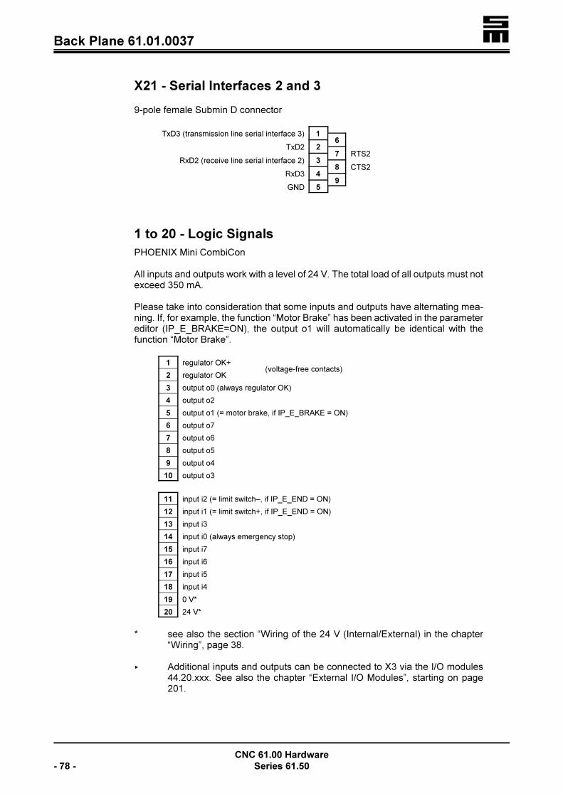
�Back Plane 61.01.0037
CNC 61.00 Hardware
- 78 - Series 61.50
X21 - Serial Interfaces 2 and 3
9-pole female Submin D connector
TxD3 (transmission line serial interface 3) 16
TxD2 27 RTS2
RxD2 (receive line serial interface 2) 38 CTS2
RxD3 49
GND 5
1 to 20 - Logic Signals
PHOENIX Mini CombiCon
All inputs and outputs work with a level of 24 V. The total load of all outputs must notexceed 350 mA.
Please take into consideration that some inputs and outputs have alternating mea-ning. If, for example, the function “Motor Brake” has been activated in the parametereditor (IP_E_BRAKE=ON), the output o1 will automatically be identical with thefunction “Motor Brake”.
1 regulator OK+(voltage-free contacts)
2 regulator OK
3 output o0 (always regulator OK)
4 output o2
5 output o1 (= motor brake, if IP_E_BRAKE = ON)
6 output o7
7 output o6
8 output o5
9 output o4
10 output o3
11 input i2 (= limit switch–, if IP_E_END = ON)
12 input i1 (= limit switch+, if IP_E_END = ON)
13 input i3
14 input i0 (always emergency stop)
15 input i7
16 input i6
17 input i5
18 input i4
19 0 V*
20 24 V*
* see also the section “Wiring of the 24 V (Internal/External) in the chapter“Wiring”, page 38.
< Additional inputs and outputs can be connected to X3 via the I/O modules44.20.xxx. See also the chapter “External I/O Modules”, starting on page201.

� Back Plane 61.01.0037
CNC 61.00 Hardware
Series 61.50 - 79 -
21 to 24 - Thermal Contact/24 V External
PHOENIX Mini CombiCon
21 thermal contact
22 24 V internal
23 24 V external
24 0 V
Wiring of the 24 V (Internal/External), see chapter “Wiring”, section “Wiring of 24 V(internal/external)”, page 38.
U / V / W - Motor Connections
< WEIDMÜLLER screw connectorsThe maximum conductor cross-section for the terminals is 10 mm².
Bus - Internal Connection
The 10-pole bus line connects the power module and up to six CNC rack modules.The bus supplies the CNC modules with the voltage of +30 V (bus voltage). Addi-tionally, statuses of the power module (readiness for operation, malfunctions) aresignaled to the CNC 61.00 modules. At the power module the bus pins are outputs,whereas at the CNC module the bus pins are inputs.
Pin Assignment
1 + 2 ground potential
3 mains OK = +24 V
4overvoltage message:0 V in case of an error24 V without error
5 +24 V
6 not assigned
7 + 8 +30 V � mains potential
9 + 10 0 V for the 30 V � mains potential
�Do not use the +30 V for any other purposes!
Mains OKThis output intra-system activates and deactivates, inter alia, the CNC modules. Ifthe main supply is not provided, the signal “mains OK” will be LOW and the CNCmodules cannot be activated. The user may use this signal via the contacts BB.
Overvoltage MessageIf an overvoltage comes up, the level of 24 V bounces to 0 V. Then the regulator inthe CNC module is deactivated (POK and the main contactor open). Error messa-ges, however, are kept.

�Back Plane 61.01.0038
CNC 61.00 Hardware
- 80 - Series 61.50
10.1.4 Back Plane 61.01.0038
Wall-mounting into a 19” rack
84 X4 Angle pulse connection, page 83
X1 Connection of first measuring system, page 81
X7 Angle pulse connection, page 84
X3 I/O expansion, page 82
X2 Terminal connection, page 82
Bus Internal connection (rear side of back plane)
X5 Bus connection (depends on the used bus system), page 83
S1 Hook switch, page 84
X6 Bus connection (depends on the used bus system), page 84
21 to 24 Transducer / analog input, page 86
25 and 26 Thermal contact / 24 V, page 86
1 to 20 Logic signals, page 85
U V W Motor connection, page 86

� Back Plane 61.01.0038
CNC 61.00 Hardware
Series 61.50 - 81 -
X1 - Connection of First Measuring System (Feedback)
15-pole female Submin D connector
Resolver Evaluation
0 V (shield) =! 19 =! S3 sine
S1 sine !< 210 !< 0 V
0 V =! 311 =! S2 cosine
S4 cosine !< 412 !< 0 V
0 V =! 513 !< R1 rotor
R3 rotor =! 614 !< 0 V
thermal contact* !< 715 !< +24 V (thermal contact*)
0 V =! 8
< If the thermal contact (*) is not evaluated, the Pins 15 and 7 must be strap-ped.
< Use a shielded cable with three pairs of wires, each of which being twisted(e. g. LIYCY 3 × 2 × 0.14). Twist mode: sine/sine; cosine/cosine; rotor/rotor
< The shield must be connected with both ends: At the CNC on the connectorshell and at the resolver, as described in the chapter “Wiring”, “General Infor-mation”, page 33.
Hall Effect Sensor Evaluation
0 V =! 19 =! sensor C
sensor A !< 210 =! sensor B
not to be wired 311 not to be wired
not to be wired 412 not to be wired
not to be wired 513 !< +14 V
free 614 !< GND
thermal contact* !< 715 !< thermal contact*
GND =! 8
< If no thermal contact (*) is connected, Pin 7 and Pin 15 must be strapped.< Use a shielded cable. Connect the shield with largest surface to the connec-
tor shell.

�Back Plane 61.01.0038
CNC 61.00 Hardware
- 82 - Series 61.50
Optical Length Measuring System
0 V =! 19 =! 0°
!< 20°10 !< 0 V
0 V =! 311 =! 90°
!< 490°12 !< 0 V
0 V =! 513 !< ref.+
ref.– =! 614 !< 0 V
thermal contact* or PTC from motor !< 715 !< thermal contact* or PTC from motor
+5 V =! 8
< If no thermal contact (*) is connected, Pin 7 and Pin 15 must be strapped.< Use a shielded cable with four pairs of wires, each of which being twisted.
Twist mode: /0°, /90°, ref.+/ref.– and +5 V/0 V. If the thermal contact is0° 90°evaluated, a shielded twisted pair cable with five pairs of wires must beused.
< For incremental encoders without difference voltage signal the Pins 9 and 11must be supplied with 5 V (Pin 8).
< Connect the shield with largest surface to the connector shell.
X2 - Terminal Connection
9-pole female Submin D connector with levels corresponding to the RS232 andRS485 specifications.
D! (RS 485) 16 D+ (RS 485)
TxD 27 CTS
RxD 38 RTS
24 V 49 0 V
GND 5
X3 - I/O Expansion
9-pole female Submin D connector
DO! 16 DO+
CLK! 27 CLK+
LD! 38 LD+
DI! 49 DI+
0 V 5
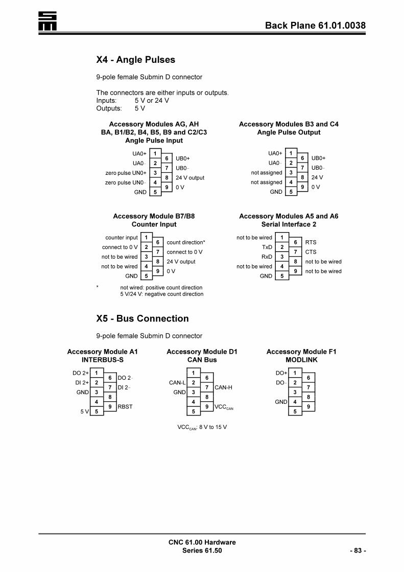
� Back Plane 61.01.0038
CNC 61.00 Hardware
Series 61.50 - 83 -
X4 - Angle Pulses
9-pole female Submin D connector
The connectors are either inputs or outputs.Inputs: 5 V or 24 VOutputs: 5 V
Accessory Modules AG, AH
BA, B1/B2, B4, B5, B9 and C2/C3
Angle Pulse Input
UA0+ 16 UB0+
UA0! 27 UB0!
zero pulse UN0+ 38 24 V output
zero pulse UN0! 49 0 V
GND 5
Accessory Modules B3 and C4
Angle Pulse Output
UA0+ 16 UB0+
UA0! 27 UB0!
not assigned 38 24 V
not assigned 49 0 V
GND 5
Accessory Module B7/B8
Counter Input
counter input 16 count direction*
connect to 0 V 27 connect to 0 V
not to be wired 38 24 V output
not to be wired 49 0 V
GND 5
* not wired: positive count direction5 V/24 V: negative count direction
Accessory Modules A5 and A6
Serial Interface 2
not to be wired 16 RTS
TxD 27 CTS
RxD 38 not to be wired
not to be wired 49 not to be wired
GND 5
X5 - Bus Connection
9-pole female Submin D connector
Accessory Module A1
INTERBUS-S
DO 2+ 16 DO 2!
DI 2+ 27 DI 2!
GND 38
49 RBST
5 V 5
Accessory Module D1
CAN Bus
16
CAN-L 27 CAN-H
GND 38
49 VCCCAN
5
VCCCAN: 8 V to 15 V
Accessory Module F1
MODLINK
DO+ 16
DO! 27
38
GND 49
5
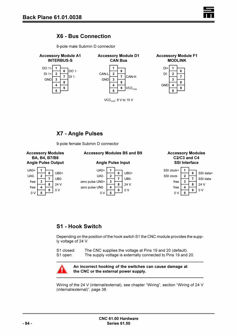
�Back Plane 61.01.0038
CNC 61.00 Hardware
- 84 - Series 61.50
X6 - Bus Connection
9-pole male Submin D connector
Accessory Module A1
INTERBUS-S
DO 1+ 16 DO 1!
DI 1+ 27 DI 1!
GND 38
49
5
Accessory Module D1
CAN Bus
16
CAN-L 27 CAN-H
GND 38
49 VCCCAN
5
VCCCAN: 8 V to 15 V
Accessory Module F1
MODLINK
DI+ 16
DI! 27
38
GND 49
5
X7 - Angle Pulses
9-pole female Submin D connector
Accessory Modules
BA, B4, B7/B8
Angle Pulse Output
UA0+ 16 UB0+
UA0! 27 UB0!
free 38 24 V
free 49 0 V
0 V 5
Accessory Modules B5 and B9
Angle Pulse Input
UA0+ 16 UB0+
UA0! 27 UB0!
zero pulse UN0+ 38 24 V
zero pulse UN0! 49 0 V
0 V 5
Accessory Modules
C2/C3 and C4
SSI Interface
SSI clock+ 16 SSI data+
SSI clock! 27 SSI data!
free 38 24 V
free 49 0 V
0 V 5
S1 - Hook Switch
Depending on the position of the hook switch S1 the CNC module provides the supp-ly voltage of 24 V.
S1 closed: The CNC supplies the voltage at Pins 19 and 20 (default).S1 open: The supply voltage is externally connected to Pins 19 and 20.
�An incorrect hooking of the switches can cause damage at
the CNC or the external power supply.
Wiring of the 24 V (internal/external), see chapter “Wiring”, section “Wiring of 24 V(internal/external)”, page 38.

� Back Plane 61.01.0038
CNC 61.00 Hardware
Series 61.50 - 85 -
1 to 20 - Logic Signals
PHOENIX Mini CombiCon
All inputs and outputs work with a level of 24 V. The total load of all outputs must notexceed 350 mA.
Please take into consideration that some inputs and outputs have alternating mea-ning. If, for example, the function “Motor Brake” has been activated in the parametereditor (IP_E_BRAKE=ON), the output o1 will automatically be identical with thefunction “Motor Brake”.
1 regulator OK+(voltage-free contacts)
2 regulator OK
3 output o0 (always regulator OK)
4 output o2
5 output o1 (= motor brake, if IP_E_BRAKE = ON)
6 output o7
7 output o6
8 output o5
9 output o4
10 output o3
11 input i2 (= limit switch–, if IP_E_END = ON)
12 input i1 (= limit switch+, if IP_E_END = ON)
13 input i3
14 input i0 (always emergency stop)
15 input i7
16 input i6
17 input i5
18 input i4
19 0 V*
20 24 V*
* see also the section “Wiring of the 24 V (Internal/External) in the chapter“Wiring”, page 38.
< Additional inputs and outputs can be connected to X3 via the I/O modules44.20.xxx. See also the chapter “External I/O Modules”, starting on page201.

�Back Plane 61.01.0038
CNC 61.00 Hardware
- 86 - Series 61.50
21 to 24 - Transducer/Analog Input
PHOENIX Mini CombiCon as inputs
Accessory Module A3
Transducer Interface
21 analog input !
22 analog input +
23 output voltage +5 V
24 output voltage !5 V
Accessory Module A4
Analog Input Module
21 analog input +
22 analog input !
23
24 GND
25 and 26 - Thermal Contact/24 V External
PHOENIX Mini CombiCon
25 24 V
26 thermal contact
Wiring of the 24 V (Internal/External), see chapter “Wiring”, section “Wiring of 24 V(internal/external)”, page 38.
U / V / W - Motor Connections
< WEIDMÜLLER screw connectorsThe maximum conductor cross-section for the terminals is 4 mm².

� Back Plane 61.01.0038
CNC 61.00 Hardware
Series 61.50 - 87 -
Bus - Internal Connection
The 10-pole bus line connects the power module and up to six CNC rack modules.The bus supplies the CNC modules with the voltage of +30 V (bus voltage). Addi-tionally, statuses of the power module (readiness for operation, malfunctions) aresignaled to the CNC 61.00 modules. At the power module the bus pins are outputs,whereas at the CNC module the bus pins are inputs.
Pin Assignment
1 + 2 ground potential
3 mains OK = +24 V
4overvoltage message:0 V in case of an error24 V without error
5 +24 V
6 not assigned
7 + 8 +30 V � mains potential
9 + 10 0 V for the 30 V � mains potential
�Do not use the +30 V for any other purposes!
Mains OKThis output intra-system activates and deactivates, inter alia, the CNC modules. Ifthe main supply is not provided, the signal “mains OK” will be LOW and the CNCmodules cannot be activated. The user may use this signal via the contacts BB.
Overvoltage MessageIf an overvoltage comes up, the level of 24 V bounces to 0 V. Then the regulator inthe CNC module is deactivated (POK and the main contactor open). Error messa-ges, however, are kept.

�Back Plane 61.01.0053
CNC 61.00 Hardware
- 88 - Series 61.50
10.1.5 Back Plane 61.01.0053 for Profibus, CAN Bus and Ether-
net
Wall-mounting into a 19” rack
X4 Angle pulse connection, page 91
X1 Connection of first measuring system, page 89
X7 Angle pulse connection, page 92
X3 I/O expansion, page 90
X2 Terminal connection, page 90
Bus Internal connection (rear side of back plane)
X5 Profibus connection, page 91
X6 Profibus connection, page 92
X33 Ethernet connection, page 93
X15 Active/passive transducer, page 93
21 to 24 Thermal contact / 24 V external, page 94
X11 CAN bus connection, page 92
U V W Motor connection, page 112
1 to 20 Logic signals, page 94
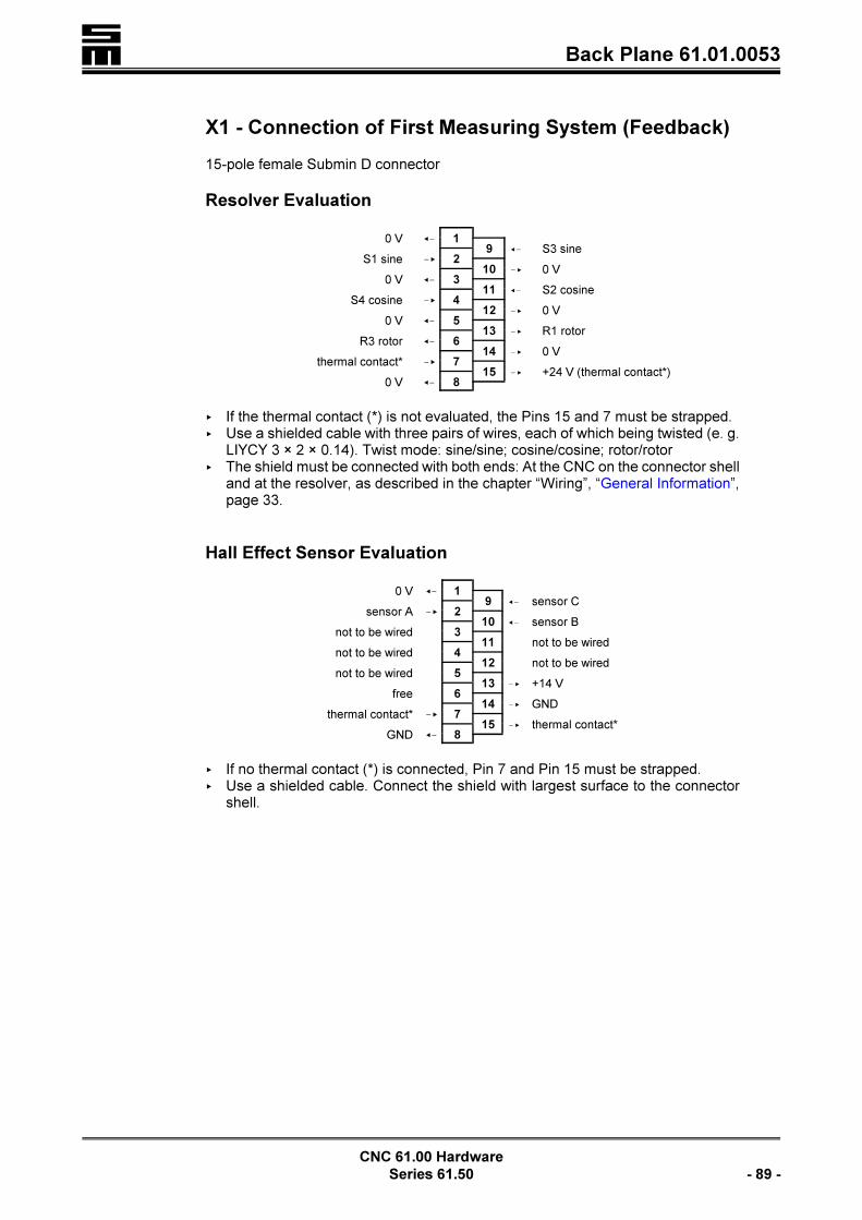
� Back Plane 61.01.0053
CNC 61.00 Hardware
Series 61.50 - 89 -
X1 - Connection of First Measuring System (Feedback)
15-pole female Submin D connector
Resolver Evaluation
0 V =! 19 =! S3 sine
S1 sine !< 210 !< 0 V
0 V =! 311 =! S2 cosine
S4 cosine !< 412 !< 0 V
0 V =! 513 !< R1 rotor
R3 rotor =! 614 !< 0 V
thermal contact* !< 715 !< +24 V (thermal contact*)
0 V =! 8
< If the thermal contact (*) is not evaluated, the Pins 15 and 7 must be strapped.< Use a shielded cable with three pairs of wires, each of which being twisted (e. g.
LIYCY 3 × 2 × 0.14). Twist mode: sine/sine; cosine/cosine; rotor/rotor< The shield must be connected with both ends: At the CNC on the connector shell
and at the resolver, as described in the chapter “Wiring”, “General Information”,page 33.
Hall Effect Sensor Evaluation
0 V =! 19 =! sensor C
sensor A !< 210 =! sensor B
not to be wired 311 not to be wired
not to be wired 412 not to be wired
not to be wired 513 !< +14 V
free 614 !< GND
thermal contact* !< 715 !< thermal contact*
GND =! 8
< If no thermal contact (*) is connected, Pin 7 and Pin 15 must be strapped.< Use a shielded cable. Connect the shield with largest surface to the connector
shell.
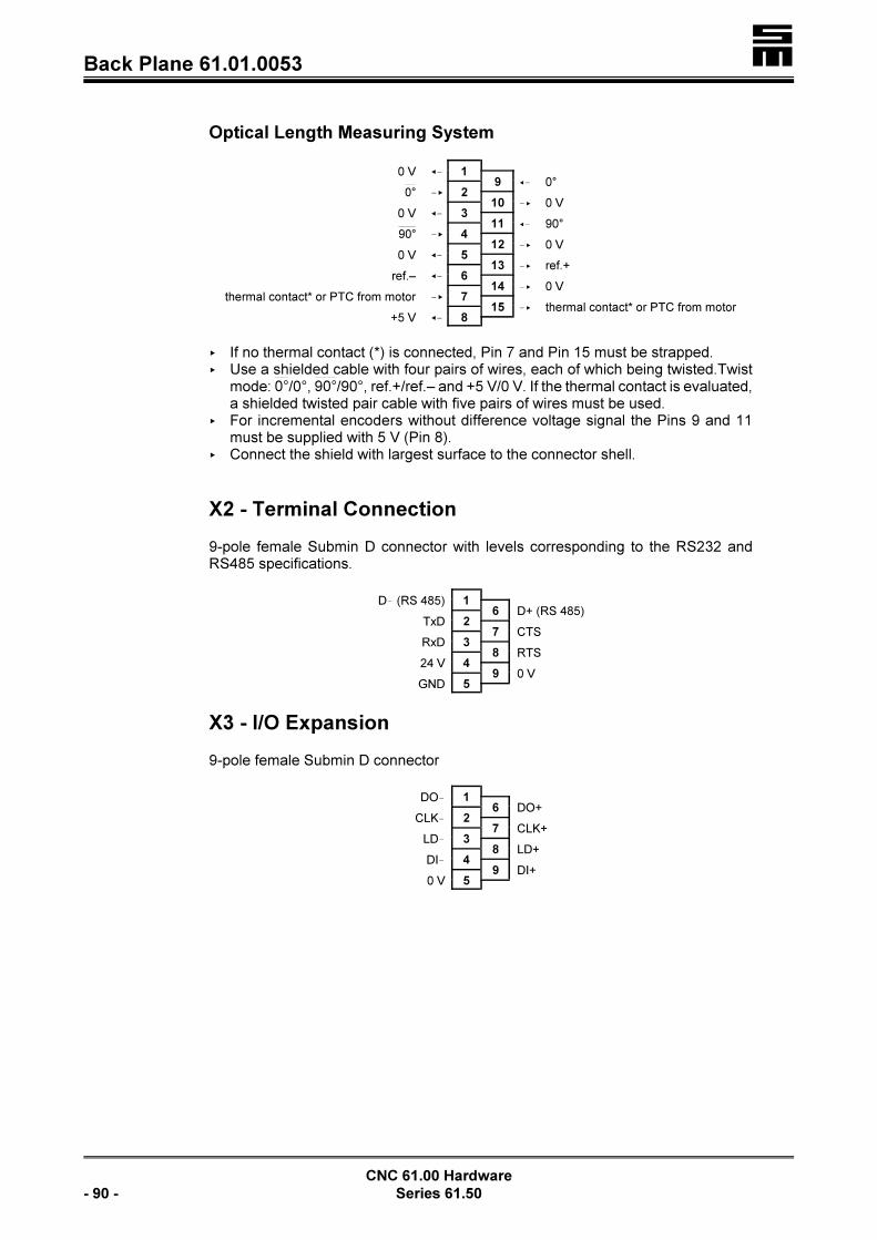
�Back Plane 61.01.0053
CNC 61.00 Hardware
- 90 - Series 61.50
Optical Length Measuring System
0 V =! 19 =! 0°
!< 20°10 !< 0 V
0 V =! 311 =! 90°
!< 490°12 !< 0 V
0 V =! 513 !< ref.+
ref.– =! 614 !< 0 V
thermal contact* or PTC from motor !< 715 !< thermal contact* or PTC from motor
+5 V =! 8
< If no thermal contact (*) is connected, Pin 7 and Pin 15 must be strapped.< Use a shielded cable with four pairs of wires, each of which being twisted.Twist
mode: /0°, /90°, ref.+/ref.– and +5 V/0 V. If the thermal contact is evaluated,0° 90°a shielded twisted pair cable with five pairs of wires must be used.
< For incremental encoders without difference voltage signal the Pins 9 and 11must be supplied with 5 V (Pin 8).
< Connect the shield with largest surface to the connector shell.
X2 - Terminal Connection
9-pole female Submin D connector with levels corresponding to the RS232 andRS485 specifications.
D! (RS 485) 16 D+ (RS 485)
TxD 27 CTS
RxD 38 RTS
24 V 49 0 V
GND 5
X3 - I/O Expansion
9-pole female Submin D connector
DO! 16 DO+
CLK! 27 CLK+
LD! 38 LD+
DI! 49 DI+
0 V 5

� Back Plane 61.01.0053
CNC 61.00 Hardware
Series 61.50 - 91 -
X4 - Angle Pulses
9-pole female Submin D connector
The connectors are either inputs or outputs.Inputs: 5 V or 24 VOutputs: 5 V
Accessory Modules AG, AH
BA, B1/B2, B4, B5, B9 and C2/C3
Angle Pulse Input
UA0+ 16 UB0+
UA0! 27 UB0!
zero pulse UN0+ 38 24 V output
zero pulse UN0! 49 0 V
GND 5
Accessory Modules B3 and C4
Angle Pulse Output
UA0+ 16 UB0+
UA0! 27 UB0!
not assigned 38 24 V
not assigned 49 0 V
GND 5
Accessory Module B7/B8
Counter Input
counter input 16 count direction*
connect to 0 V 27 connect to 0 V
not to be wired 38 24 V output
not to be wired 49 0 V
GND 5
* not wired: positive count direction5 V/24 V: negative count direction
Accessory Modules A5 and A6
Serial Interface 2
not to be wired 16 RTS
TxD 27 CTS
RxD 38 not to be wired
not to be wired 49 not to be wired
GND 5
X5 - Profibus Connection
9-pole female Submin D connector
shield 16 VP
27
RxD/TxD-P 38 RxD/TxD-N
49
DGND 5

�Back Plane 61.01.0053
CNC 61.00 Hardware
- 92 - Series 61.50
X6 - Profibus Connection
9-pole male Submin D connector
shield 16 VP
27
RxD/TxD-P 38 RxD/TxD-N
49
DGND 5
X7 - Angle Pulses
9-pole female Submin D connector
Accessory Modules
BA, B4, B7/B8
Angle Pulse Output
UA0+ 16 UB0+
UA0! 27 UB0!
free 38 24 V
free 49 0 V
0 V 5
Accessory Modules B5 and B9
Angle Pulse Input
UA0+ 16 UB0+
UA0! 27 UB0!
zero pulse UN0+ 38 24 V
zero pulse UN0! 49 0 V
0 V 5
Accessory Modules
C2/C3 and C4
SSI Interface
SSI clock+ 16 SSI data+
SSI clock! 27 SSI data!
free 38 24 V
free 49 0 V
0 V 5
X11 - CAN Bus Connection
9-pole female Submin D connector
16
CAN-L 27 CAN-H
GND 38
49 VCCCAN
5
VCCCAN: 8 V to 15 V

� Back Plane 61.01.0053
CNC 61.00 Hardware
Series 61.50 - 93 -
X15 - Active/Passive Transducer
9-pole female Submin D connector
Accessory Module AG
analog input 1- 16 analog input 1+
analog input 2- 27 analog input 2+
output voltage +5 V 38 output voltage !5 V
49 GND
5
Accessory Module AH
analog input 1 16 calibrating signal 1
analog input 2 27 calibrating signal 2
supply voltage +12 V 38 supply voltage !12 V
49 GND
5
X33 - Ethernet Connection
RJ45 female connector (Western)
Pin Designation
1 TX+
2 TX!
3 RX+
4 not connected
5 not connected
6 RX!
7 not connected
8 not connected

�Back Plane 61.01.0053
CNC 61.00 Hardware
- 94 - Series 61.50
1 to 20 - Logic Signals
PHOENIX Mini CombiCon
All inputs and outputs work with a level of 24 V. The total load of all outputs must notexceed 350 mA.
Please take into consideration that some inputs and outputs have alternating mea-ning. If, for example, the function “Motor Brake” has been activated in the parametereditor (IP_E_BRAKE=ON), the output o1 will automatically be identical with thefunction “Motor Brake”.
1 regulator OK+(voltage-free contacts)
2 regulator OK
3 output o0 (always regulator OK)
4 output o2
5 output o1 (= motor brake, if IP_E_BRAKE = ON)
6 output o7
7 output o6
8 output o5
9 output o4
10 output o3
11 input i2 (= limit switch–, if IP_E_END = ON)
12 input i1 (= limit switch+, if IP_E_END = ON)
13 input i3
14 input i0 (always emergency stop)
15 input i7
16 input i6
17 input i5
18 input i4
19 0 V*
20 24 V*
* see also the section “Wiring of the 24 V (Internal/External) in the chapter “Wi-ring”, page 38.
Additional inputs and outputs can be connected to X3 via the I/O modules 44.20.xxx.See also the chapter “External I/O Modules”, starting on page 201.
21 to 24 - Thermal Contact/24 V External
PHOENIX Mini CombiCon
21 thermal contact
22 24 V internal
23 24 V external
24 0 V
Wiring of the 24 V (Internal/External), see chapter “Wiring”, section “Wiring of 24 V(internal/external)”, page 38.

� Back Plane 61.01.0053
CNC 61.00 Hardware
Series 61.50 - 95 -
U / V / W - Motor Connections
< WEIDMÜLLER screw connectorsThe maximum conductor cross-section for the terminals is 4 mm².
Bus - Internal Connection
The 10-pole bus line connects the power module and up to six CNC rack modules.The bus supplies the CNC modules with the voltage of +30 V (bus voltage). Addi-tionally, statuses of the power module (readiness for operation, malfunctions) aresignaled to the CNC 61.00 modules. At the power module the bus pins are outputs,whereas at the CNC module the bus pins are inputs.
Pin Assignment
1 + 2 ground potential
3 mains OK = +24 V
4overvoltage message:0 V in case of an error24 V without error
5 +24 V
6 not assigned
7 + 8 +30 V � mains potential
9 + 10 0 V for the 30 V � mains potential
�Do not use the +30 V for any other purposes!
Mains OKThis output intra-system activates and deactivates, inter alia, the CNC modules. Ifthe main supply is not provided, the signal “mains OK” will be LOW and the CNCmodules cannot be activated. The user may use this signal via the contacts BB.
Overvoltage MessageIf an overvoltage comes up, the level of 24 V bounces to 0 V. Then the regulator inthe CNC module is deactivated (POK and the main contactor open). Error messa-ges, however, are kept.

�Back Plane 61.01.0058
CNC 61.00 Hardware
- 96 - Series 61.50
10.1.6 Back Plane 61.01.0058 for Profibus, CAN Bus and Ether-
net
Hinged-frame mounting into a 19” rack
X1 Connection of first measuring system, page 97
+UB Intermediate circuit voltage
X2 Terminal connection, page 98
X19 Profibus connection, page 100
Bus Internal connection, page 103
X33 Ethernet connection, page 101
X21 Serial interfaces 2 and 3, page 101
W V Motor connection
1 to 20 Logic signals, page 102
U Motor connection
!UB Intermediate circuit voltage
21 to 24 Thermal contact / 24 V external, page 102
X15 Active/passive transducer, page 100
X4 Angle pulse connection, page 99
X7 Angle pulse connection, page 99
X3 I/O expansion, page 98
X11 CAN bus connection, page 100

� Back Plane 61.01.0058
CNC 61.00 Hardware
Series 61.50 - 97 -
X1 - Connection of First Measuring System (Feedback)
15-pole female Submin D connector
Resolver Evaluation
0 V =! 19 =! S3 sine
S1 sine !< 210 !< 0 V
0 V =! 311 =! S2 cosine
S4 cosine !< 412 !< 0 V
0 V =! 513 !< R1 rotor
R3 rotor =! 614 !< 0 V
thermal contact* !< 715 !< +24 V (thermal contact*)
0 V =! 8
< If the thermal contact (*) is not evaluated, the Pins 15 and 7 must be strapped.< Use a shielded cable with three pairs of wires, each of which being twisted (e. g.
LIYCY 3 × 2 × 0.14). Twist mode: sine/sine; cosine/cosine; rotor/rotor< The shield must be connected with both ends: At the CNC on the connector shell
and at the resolver, as described in the chapter “Wiring”, “General Information”,page 33.
Hall Effect Sensor Evaluation
0 V =! 19 =! sensor C
sensor A !< 210 =! sensor B
not to be wired 311 not to be wired
not to be wired 412 not to be wired
not to be wired 513 !< +14 V
free 614 !< GND
thermal contact* !< 715 !< thermal contact*
GND =! 8
< If no thermal contact (*) is connected, Pin 7 and Pin 15 must be strapped.< Use a shielded cable. Connect the shield with largest surface to the connector
shell.

�Back Plane 61.01.0058
CNC 61.00 Hardware
- 98 - Series 61.50
Optical Length Measuring System
0 V =! 19 =! 0°
!< 20°10 !< 0 V
0 V =! 311 =! 90°
!< 490°12 !< 0 V
0 V =! 513 !< ref.+
ref.– =! 614 !< 0 V
thermal contact* or PTC from motor !< 715 !< thermal contact* or PTC from motor
+5 V =! 8
< If no thermal contact (*) is connected, Pin 7 and Pin 15 must be strapped.< Use a shielded cable with four pairs of wires, each of which being twisted.Twist
mode: /0°, /90°, ref.+/ref.– and +5 V/0 V. If the thermal contact is evaluated,0° 90°a shielded twisted pair cable with five pairs of wires must be used.
< For incremental encoders without difference voltage signal the Pins 9 and 11must be supplied with 5 V (Pin 8).
< Connect the shield with largest surface to the connector shell.
X2 - Terminal Connection
9-pole female Submin D connector with levels corresponding to the RS232 andRS485 specifications.
D! (RS 485) 16 D+ (RS 485)
TxD 27 CTS
RxD 38 RTS
24 V 49 0 V
GND 5
X3 - I/O Expansion
9-pole female Submin D connector
DO! 16 DO+
CLK! 27 CLK+
LD! 38 LD+
DI! 49 DI+
0 V 5

� Back Plane 61.01.0058
CNC 61.00 Hardware
Series 61.50 - 99 -
X4 - Angle Pulses
9-pole female Submin D connector
The connectors are either inputs or outputs.Inputs: 5 V or 24 VOutputs: 5 V
Accessory Modules AG, AH
BA, B1/B2, B4, B5, B9 and C2/C3
Angle Pulse Input
UA0+ 16 UB0+
UA0! 27 UB0!
zero pulse UN0+ 38 24 V output
zero pulse UN0! 49 0 V
GND 5
Accessory Modules B3 and C4
Angle Pulse Output
UA0+ 16 UB0+
UA0! 27 UB0!
not assigned 38 24 V
not assigned 49 0 V
GND 5
Accessory Module B7/B8
Counter Input
counter input 16 count direction*
connect to 0 V 27 connect to 0 V
not to be wired 38 24 V output
not to be wired 49 0 V
GND 5
* not wired: positive count direction5 V/24 V: negative count direction
Accessory Modules A5 and A6
Serial Interface 2
not to be wired 16 RTS
TxD 27 CTS
RxD 38 not to be wired
not to be wired 49 not to be wired
GND 5
X7 - Angle Pulses
9-pole female Submin D connector
Accessory Modules
BA, B4, B7/B8
Angle Pulse Output
UA0+ 16 UB0+
UA0! 27 UB0!
free 38 24 V
free 49 0 V
0 V 5
Accessory Modules B5 and B9
Angle Pulse Input
UA0+ 16 UB0+
UA0! 27 UB0!
zero pulse UN0+ 38 24 V
zero pulse UN0! 49 0 V
0 V 5
Accessory Modules
C2/C3 and C4
SSI Interface
SSI clock+ 16 SSI data+
SSI clock! 27 SSI data!
free 38 24 V
free 49 0 V
0 V 5

�Back Plane 61.01.0058
CNC 61.00 Hardware
- 100 - Series 61.50
X11 - CAN Bus Connection
9-pole female Submin D connector
16
CAN-L 27 CAN-H
GND 38
49 VCCCAN
5
VCCCAN: 8 V to 15 V
X15 - Active/Passive Transducer
9-pole female Submin D connector
Accessory Module AG
analog input 1- 16 analog input 1+
analog input 2- 27 analog input 2+
output voltage +5 V 38 output voltage !5 V
49 GND
5
Accessory Module AH
analog input 1 16 calibrating signal 1
analog input 2 27 calibrating signal 2
supply voltage +12 V 38 supply voltage !12 V
49 GND
5
X19 - Profibus Connection
9-pole female Submin D connector
shield 16 VP
27
RxD/TxD-P 38 RxD/TxD-N
49
DGND 5

� Back Plane 61.01.0058
CNC 61.00 Hardware
Series 61.50 - 101 -
X21 - Serial Interfaces 2 and 3
9-pole female Submin D connector
TxD3 (transmission line serial interface 3) 16
TxD2 27 RTS2
RxD2 (receive line serial interface 2) 38 CTS2
RxD3 49
GND 5
X33 - Ethernet Connection
RJ45 female connector (Western)
Pin Designation
1 TX+
2 TX!
3 RX+
4 not connected
5 not connected
6 RX!
7 not connected
8 not connected

�Back Plane 61.01.0058
CNC 61.00 Hardware
- 102 - Series 61.50
1 to 20 - Logic Signals
PHOENIX Mini CombiCon
All inputs and outputs work with a level of 24 V. The total load of all outputs must notexceed 350 mA.
Please take into consideration that some inputs and outputs have alternating mea-ning. If, for example, the function “Motor Brake” has been activated in the parametereditor (IP_E_BRAKE=ON), the output o1 will automatically be identical with thefunction “Motor Brake”.
1 regulator OK+(voltage-free contacts)
2 regulator OK
3 output o0 (always regulator OK)
4 output o2
5 output o1 (= motor brake, if IP_E_BRAKE = ON)
6 output o7
7 output o6
8 output o5
9 output o4
10 output o3
11 input i2 (= limit switch–, if IP_E_END = ON)
12 input i1 (= limit switch+, if IP_E_END = ON)
13 input i3
14 input i0 (always emergency stop)
15 input i7
16 input i6
17 input i5
18 input i4
19 0 V*
20 24 V*
* see also the section “Wiring of the 24 V (Internal/External) in the chapter “Wi-ring”, page 38.
Additional inputs and outputs can be connected to X3 via the I/O modules 44.20.xxx.See also the chapter “External I/O Modules”, starting on page 201.
21 to 24 - Thermal Contact/24 V External
PHOENIX Mini CombiCon
21 thermal contact
22 24 V internal
23 24 V external
24 0 V
Wiring of the 24 V (Internal/External), see chapter “Wiring”, section “Wiring of 24 V(internal/external)”, page 38.

� Back Plane 61.01.0058
CNC 61.00 Hardware
Series 61.50 - 103 -
U / V / W - Motor Connection
< WEIDMÜLLER screw connectorsThe maximum conductor cross-section for the terminals is 10 mm².
Bus - Internal Connection
The 10-pole bus line connects the power module and up to six CNC rack modules.The bus supplies the CNC modules with the voltage of +30 V (bus voltage). Addi-tionally, statuses of the power module (readiness for operation, malfunctions) aresignaled to the CNC 61.00 modules. At the power module the bus pins are outputs,whereas at the CNC module the bus pins are inputs.
Pin Assignment
1 + 2 ground potential
3 mains OK = +24 V
4overvoltage message:0 V in case of an error24 V without error
5 +24 V
6 not assigned
7 + 8 +30 V � mains potential
9 + 10 0 V for the 30 V � mains potential
�Do not use the +30 V for any other purposes!
Mains OKThis output intra-system activates and deactivates, inter alia, the CNC modules. Ifthe main supply is not provided, the signal “mains OK” will be LOW and the CNCmodules cannot be activated. The user may use this signal via the contacts BB.
Overvoltage MessageIf an overvoltage comes up, the level of 24 V bounces to 0 V. Then the regulator inthe CNC module is deactivated (POK and the main contactor open). Error messa-ges, however, are kept.

�Back Plane 61.01.0060
CNC 61.00 Hardware
- 104 - Series 61.50
10.1.7 Back Plane 61.01.0060 for INTERBUS, MODLINK and
CAN Bus
Mounting as swing frame into 19” rack
X1 Connection of first measuring system, page 105
+UB Intermediate circuit voltage
X6 INTERBUS connection, page 108X5 INTERBUS connection, page 107
X2 Terminal connection, page 106
Bus Internal connection, page 112
X33 Ethernet connection, page 110
V W Motor connection
X10 MODLINK connection, page 109
X9 MODLINK connection, page 108
1 to 20 Logic signals, page 110
U Motor connection
!UB Intermediate circuit voltage
21 to 24 Thermal contact/24 V external, page 112
X14 Transducer/analog input, page 109
X4 Angle pulse connection, page 107X7 Angle pulse connection, page 108
X3 I/O expansion, page 106
X11 CAN bus connection, page 109

� Back Plane 61.01.0060
CNC 61.00 Hardware
Series 61.50 - 105 -
X1 - Connection of First Measuring System (Feedback)
15-pole female Submin D connector
Resolver Evaluation
0 V =! 19 =! S3 sine
S1 sine !< 210 !< 0 V
0 V =! 311 =! S2 cosine
S4 cosine !< 412 !< 0 V
0 V =! 513 !< R1 rotor
R3 rotor =! 614 !< 0 V
thermal contact* !< 715 !< +24 V (thermal contact*)
0 V =! 8
< If the thermal contact (*) is not evaluated, the Pins 15 and 7 must be strapped.< Use a shielded cable with three pairs of wires, each of which being twisted (e. g.
LIYCY 3 × 2 × 0.14). Twist mode: sine/sine; cosine/cosine; rotor/rotor< The shield must be connected with both ends: At the CNC on the connector shell
and at the resolver, as described in the chapter “Wiring”, “General Information”,page 33.
Hall Effect Sensor Evaluation
0 V =! 19 =! sensor C
sensor A !< 210 =! sensor B
not to be wired 311 not to be wired
not to be wired 412 not to be wired
not to be wired 513 !< +14 V
free 614 !< GND
thermal contact* !< 715 !< thermal contact*
GND =! 8
< If no thermal contact (*) is connected, Pin 7 and Pin 15 must be strapped.< Use a shielded cable. Connect the shield with largest surface to the connector
shell.

�Back Plane 61.01.0060
CNC 61.00 Hardware
- 106 - Series 61.50
Optical Length Measuring System
0 V =! 19 =! 0°
!< 20°10 !< 0 V
0 V =! 311 =! 90°
!< 490°12 !< 0 V
0 V =! 513 !< ref.+
ref.– =! 614 !< 0 V
thermal contact* or PTC from motor !< 715 !< thermal contact* or PTC from motor
+5 V =! 8
< If no thermal contact (*) is connected, Pin 7 and Pin 15 must be strapped.< Use a shielded cable with four pairs of wires, each of which being twisted.Twist
mode: /0°, /90°, ref.+/ref.– and +5 V/0 V. If the thermal contact is evaluated,0° 90°a shielded twisted pair cable with five pairs of wires must be used.
< For incremental encoders without difference voltage signal the Pins 9 and 11must be supplied with 5 V (Pin 8).
< Connect the shield with largest surface to the connector shell.
X2 - Terminal Connection
9-pole female Submin D connector with levels corresponding to the RS232 andRS485 specifications.
D! (RS 485) 16 D+ (RS 485)
TxD 27 CTS
RxD 38 RTS
24 V 49 0 V
GND 5
X3 - I/O Expansion
9-pole female Submin D connector
DO! 16 DO+
CLK! 27 CLK+
LD! 38 LD+
DI! 49 DI+
0 V 5

� Back Plane 61.01.0060
CNC 61.00 Hardware
Series 61.50 - 107 -
X4 - Angle Pulses
9-pole female Submin D connector
The connectors are either inputs or outputs.Inputs: 5 V or 24 VOutputs: 5 V
Accessory Modules AG, AH
BA, B1/B2, B4, B5, B9 and C2/C3
Angle Pulse Input
UA0+ 16 UB0+
UA0! 27 UB0!
zero pulse UN0+ 38 24 V output
zero pulse UN0! 49 0 V
GND 5
Accessory Modules B3 and C4
Angle Pulse Output
UA0+ 16 UB0+
UA0! 27 UB0!
not assigned 38 24 V
not assigned 49 0 V
GND 5
Accessory Module B7/B8
Counter Input
counter input 16 count direction*
connect to 0 V 27 connect to 0 V
not to be wired 38 24 V output
not to be wired 49 0 V
GND 5
* not wired: positive count direction5 V/24 V: negative count direction
Accessory Modules A5 and A6
Serial Interface 2
not to be wired 16 RTS
TxD 27 CTS
RxD 38 not to be wired
not to be wired 49 not to be wired
GND 5
X5 - INTERBUS Connection
9-pole female Submin D connector
DO 2+ 16 DO 2!
DI 2+ 27 DI 2!
GND 38
49 RBST
5 V 5

�Back Plane 61.01.0060
CNC 61.00 Hardware
- 108 - Series 61.50
X6 - INTERBUS Connection
9-pole male Submin D connector
DO 1+ 16 DO 1!
DI 1+ 27 DI 1!
GND 38
49 5 V
5
X7 - Angle Pulses
9-pole female Submin D connector
Accessory Modules
BA, B4, B7/B8
Angle Pulse Output
UA0+ 16 UB0+
UA0! 27 UB0!
free 38 24 V
free 49 0 V
0 V 5
Accessory Modules B5 and B9
Angle Pulse Input
UA0+ 16 UB0+
UA0! 27 UB0!
zero pulse UN0+ 38 24 V
zero pulse UN0! 49 0 V
0 V 5
Accessory Modules
C2/C3 and C4
SSI Interface
SSI clock+ 16 SSI data+
SSI clock! 27 SSI data!
free 38 24 V
free 49 0 V
0 V 5
X9 - MODLINK Connection
9-pole female Submin D connector
DO+ 16
DO! 27
38 5 V
GND 49
GND 5

� Back Plane 61.01.0060
CNC 61.00 Hardware
Series 61.50 - 109 -
X10 - MODLINK Connection
9-pole male Submin D connector
DI+ 16
DI! 27
38 5 V
GND 49
GND 5
X11 - CAN Bus Connection
9-pole female Submin D connector
16
CAN-L 27 CAN-H
GND 38
49 VCCCAN
5
VCCCAN: 8 V to 15 V
X14 - Transducer/Analog Input
9-pole female Submin D connector
Accessory Modules A3, A5, AA and AE
Transducer Input
analog input - 16 analog input +
27
output voltage +5 V 38 output voltage !5 V
49 GND
5
Accessory Modules A4 and A6
Analog Input
analog input + 16 analog input !
27
38 GND
49 GND
5
Accessory Module AF
Active Transducer
analog input (±5 V) 16 calibrating signal
27
supply voltage +12 V 38 supply voltage !12 V
49 GND (shared ground)
5

�Back Plane 61.01.0060
CNC 61.00 Hardware
- 110 - Series 61.50
X33 - Ethernet Connection
RJ45 female connector (Western)
Pin Designation
1 TX+
2 TX!
3 RX+
4 not connected
5 not connected
6 RX!
7 not connected
8 not connected
1 to 20 - Logic Signals
PHOENIX Mini CombiCon
All inputs and outputs work with a level of 24 V. The total load of all outputs must notexceed 350 mA.
Please take into consideration that some inputs and outputs have alternating mea-ning. If, for example, the function “Motor Brake” has been activated in the parametereditor (IP_E_BRAKE=ON), the output o1 will automatically be identical with thefunction “Motor Brake”.
1 regulator OK+(voltage-free contacts)
2 regulator OK
3 output o0 (always regulator OK)
4 output o2
5 output o1 (= motor brake, if IP_E_BRAKE = ON)
6 output o7
7 output o6
8 output o5
9 output o4
10 output o3
11 input i2 (= limit switch–, if IP_E_END = ON)
12 input i1 (= limit switch+, if IP_E_END = ON)
13 input i3
14 input i0 (always emergency stop)
15 input i7
16 input i6
17 input i5
18 input i4
19 0 V*
20 24 V*
* see also section “Wiring of the 24 V (Internal/External) in chapter “Wiring”.
Additional inputs and outputs can be connected to X3 via the I/O modules 44.20.xxx.

� Back Plane 61.01.0060
CNC 61.00 Hardware
Series 61.50 - 111 -
See also the chapter “External I/O Modules”, starting on page 201.

�Back Plane 61.01.0060
CNC 61.00 Hardware
- 112 - Series 61.50
21 to 24 - Thermal Contact/24 V External
PHOENIX Mini CombiCon
21 thermal contact
22 24 V internal
23 24 V external
24 0 V
Wiring of the 24 V (Internal/External), see chapter “Wiring”, section “Wiring of 24 V(internal/external)”, page 38.
U / V / W - Motor Connection
< WEIDMÜLLER screw connectorsThe maximum conductor cross-section for the terminals is 10 mm².
Bus - Internal Connection
The 12-pole bus line connects the power module and up to six CNC rack modules.The bus supplies the CNC modules with the voltage of +30 V (bus voltage). Addi-tionally, statuses of the power module (readiness for operation, malfunctions) aresignaled to the CNC 61.00 modules. At the power module the bus pins are outputs,whereas at the CNC module the bus pins are inputs.
The bus moreover provides the volt-free +5 V/GND that can be loaded with up to 1.8A. The potentiometer +5 V MSY at the front panel enables the precise adjustment ofthe 5 V.
Pin Assignment
1 +5 V
2 GND
3 + 4 earth potential
5 mains OK = +24 V
6 overvoltage message
7 +24 V
8 not assigned
9 + 10 +30 V � mains potential
11 + 12 0 V for the 30 V � mains potential
�Do not use the +30 V for any other purposes!
Mains OKThis output intra-system activates and deactivates, inter alia, the CNC modules. Ifthe main supply is not provided, the signal “mains OK” will be LOW and the CNCmodules cannot be activated. The user may use this signal via the contacts BB.

� Back Plane 61.01.0060
CNC 61.00 Hardware
Series 61.50 - 113 -
Overvoltage MessageIf an overvoltage comes up, the level of 24 V bounces to 0 V. Then the regulator inthe CNC module is deactivated (POK and the main contactor open). Error messa-ges, however, are kept.

�Back Plane 61.01.0060
CNC 61.00 Hardware
- 114 - Series 61.50

� Back Plane 61.01.0019
CNC 61.00 Hardware
Series 61.50 - 115 -
10.2 Back Planes for the Compact System
10.2.1 Back Plane 61.01.0019
Mounting into a compact housing for wall mounting
X7 Angle pulse connection, page 120
X4 Angle pulse connection, page 118
X3 I/O expansion, page 117
X2 Terminal connection, page 117
PE Earth conductor
L1 L2 L3 Mains input for generating the intermediate circuit voltage
X1 Connection of first measuring system, page 116
S1 Hook switch, page 120
X8 Profibus connection, page 120
X5 Bus connection, depends on the used bus system, page119
X6 Bus connection, depends on the used bus system, page119
1 to 20 Logic signals, page 121
21 to 24 Transducer /analog input, page 122
25 and 26 24 V / thermal contact, page 122
X10 / X11 Fan connection
L1 L2 Mains input for the logic supply
Rex
External ballast resistor
+UB Intermediate circuit voltage
PE Earth conductor
U V W Motor connection

�Back Plane 61.01.0019
CNC 61.00 Hardware
- 116 - Series 61.50
X1 - Connection of First Measuring System (Feedback)
15-pole female Submin D connector
Resolver Evaluation
0 V (shield) =! 19 =! S3 sine
S1 sine !< 210 !< 0 V
0 V =! 311 =! S2 cosine
S4 cosine !< 412 !< 0 V
0 V =! 513 !< R1 rotor
R3 rotor =! 614 !< 0 V
thermal contact* !< 715 !< +24 V (thermal contact*)
0 V =! 8
< If the thermal contact (*) is not evaluated, the Pins 15 and 7 must be strap-ped.
< Use a shielded cable with three pairs of wires, each of which being twisted(e. g. LIYCY 3 × 2 × 0.14). Twist mode: sine/sine; cosine/cosine; rotor/rotor
< The shield must be connected with both ends: At the CNC on the connectorshell and at the resolver, as described in the chapter “Wiring”, “General Infor-mation”, page 33.
Hall Effect Sensor Evaluation
0 V =! 19 =! sensor C
sensor A !< 210 =! sensor B
not to be wired 311 not to be wired
not to be wired 412 not to be wired
not to be wired 513 !< +14 V
free 614 !< GND
thermal contact* !< 715 !< thermal contact*
GND =! 8
< If no thermal contact (*) is connected, Pin 7 and Pin 15 must be strapped.< Use a shielded cable. Connect the shield with largest surface to the connec-
tor shell.

� Back Plane 61.01.0019
CNC 61.00 Hardware
Series 61.50 - 117 -
Optical Length Measuring System
0 V =! 19 =! 0°
0° !< 210 !< 0 V
0 V =! 311 =! 90°
90° !< 412 !< 0 V
0 V =! 513 !< ref.+
ref.– =! 614 !< 0 V
thermal contact* or PTC from motor !< 715 !< thermal contact* or PTC from motor
+5 V =! 8
< If no thermal contact (*) is connected, Pin 7 and Pin 15 must be strapped.< Use a shielded cable with four pairs of wires, each of which being twisted.
Twist mode: /0°, /90°, ref.+/ref.– and +5 V/0 V. If the thermal contact is0° 90°evaluated, a shielded twisted pair cable with five pairs of wires must beused.
< For incremental encoders without difference voltage signal the Pins 9 and 11must be supplied with 5 V (Pin 8).
< Connect the shield with largest surface to the connector shell.
X2 - Terminal Connection
9-pole female Submin D connector with levels corresponding to the RS232 andRS485 specifications.
D! (RS 485) 16 D+ (RS 485)
TxD 27 CTS
RxD 38 RTS
24 V 49 0 V
GND 5
X3 - I/O Expansion
9-pole female Submin D connector
DO! 16 DO+
CLK! 27 CLK+
LD! 38 LD+
DI! 49 DI+
0 V 5

�Back Plane 61.01.0019
CNC 61.00 Hardware
- 118 - Series 61.50
X4 - Angle Pulses
9-pole female Submin D connector
The connectors are either inputs or outputs.Inputs: 5 V or 24 VOutputs: 5 V
Accessory Modules AG, AH
BA, B1/B2, B4, B5, B9 and C2/C3
Angle Pulse Input
UA0+ 16 UB0+
UA0! 27 UB0!
zero pulse UN0+ 38 24 V output
zero pulse UN0! 49 0 V
GND 5
Accessory Modules B3 and C4
Angle Pulse Output
UA0+ 16 UB0+
UA0! 27 UB0!
not assigned 38 24 V
not assigned 49 0 V
GND 5
Accessory Module B7/B8
Counter Input
counter input 16 count direction*
connect to 0 V 27 connect to 0 V
not to be wired 38 24 V output
not to be wired 49 0 V
GND 5
* not wired: positive count direction5 V/24 V: negative count direction
Accessory Modules A5 and A6
Serial Interface 2
not to be wired 16 RTS
TxD 27 CTS
RxD 38 not to be wired
not to be wired 49 not to be wired
GND 5
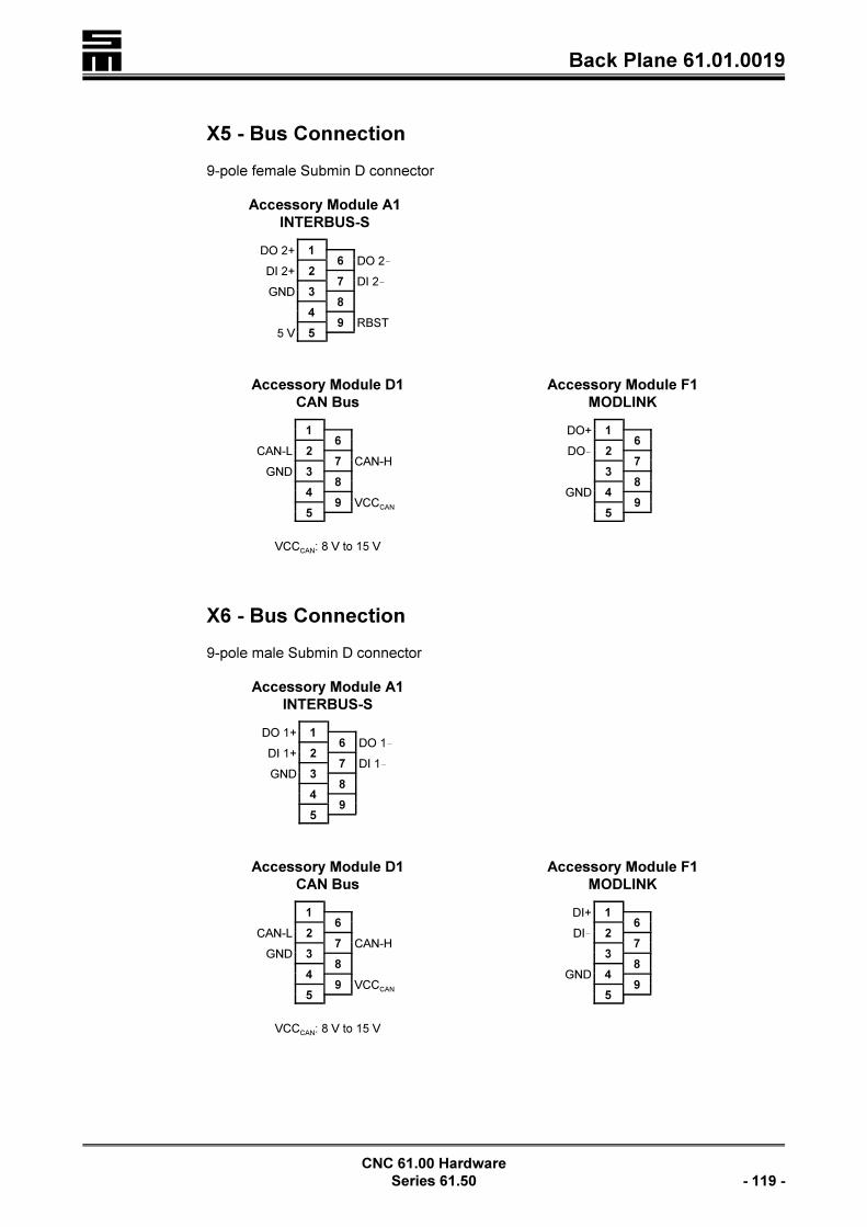
� Back Plane 61.01.0019
CNC 61.00 Hardware
Series 61.50 - 119 -
X5 - Bus Connection
9-pole female Submin D connector
Accessory Module A1
INTERBUS-S
DO 2+ 16 DO 2!
DI 2+ 27 DI 2!
GND 38
49 RBST
5 V 5
Accessory Module D1
CAN Bus
16
CAN-L 27 CAN-H
GND 38
49 VCCCAN
5
VCCCAN: 8 V to 15 V
Accessory Module F1
MODLINK
DO+ 16
DO! 27
38
GND 49
5
X6 - Bus Connection
9-pole male Submin D connector
Accessory Module A1
INTERBUS-S
DO 1+ 16 DO 1!
DI 1+ 27 DI 1!
GND 38
49
5
Accessory Module D1
CAN Bus
16
CAN-L 27 CAN-H
GND 38
49 VCCCAN
5
VCCCAN: 8 V to 15 V
Accessory Module F1
MODLINK
DI+ 16
DI! 27
38
GND 49
5
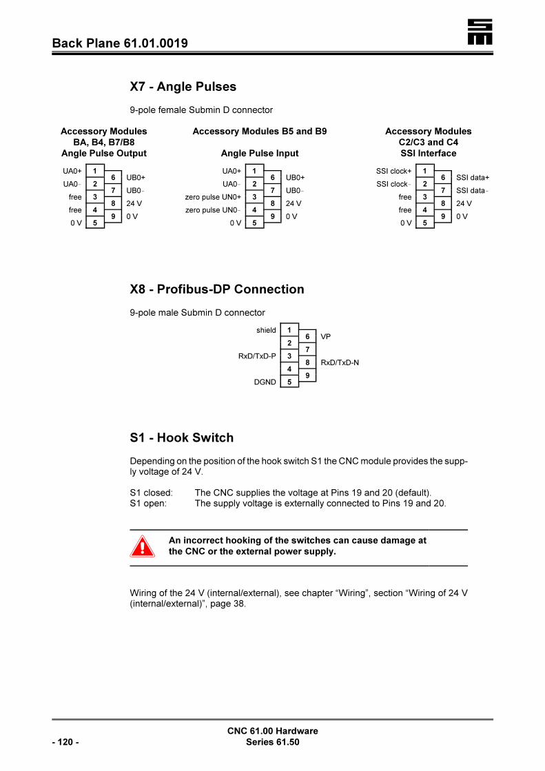
�Back Plane 61.01.0019
CNC 61.00 Hardware
- 120 - Series 61.50
X7 - Angle Pulses
9-pole female Submin D connector
Accessory Modules
BA, B4, B7/B8
Angle Pulse Output
UA0+ 16 UB0+
UA0! 27 UB0!
free 38 24 V
free 49 0 V
0 V 5
Accessory Modules B5 and B9
Angle Pulse Input
UA0+ 16 UB0+
UA0! 27 UB0!
zero pulse UN0+ 38 24 V
zero pulse UN0! 49 0 V
0 V 5
Accessory Modules
C2/C3 and C4
SSI Interface
SSI clock+ 16 SSI data+
SSI clock! 27 SSI data!
free 38 24 V
free 49 0 V
0 V 5
X8 - Profibus-DP Connection
9-pole male Submin D connector
shield 16 VP
27
RxD/TxD-P 38 RxD/TxD-N
49
DGND 5
S1 - Hook Switch
Depending on the position of the hook switch S1 the CNC module provides the supp-ly voltage of 24 V.
S1 closed: The CNC supplies the voltage at Pins 19 and 20 (default).S1 open: The supply voltage is externally connected to Pins 19 and 20.
�An incorrect hooking of the switches can cause damage at
the CNC or the external power supply.
Wiring of the 24 V (internal/external), see chapter “Wiring”, section “Wiring of 24 V(internal/external)”, page 38.

� Back Plane 61.01.0019
CNC 61.00 Hardware
Series 61.50 - 121 -
U / V / W / PE - Motor Connections
< PHOENIX screw connectorsThe maximum conductor cross-section for the terminals is 2.5 mm².
1 to 20 - Logic Signals
PHOENIX Mini CombiCon
All inputs and outputs work with a level of 24 V. The total load of all outputs must notexceed 350 mA.
Please take into consideration that some inputs and outputs have alternating mea-ning. If, for example, the function “Motor Brake” has been activated in the parametereditor (IP_E_BRAKE=ON), the output o1 will automatically be identical with thefunction “Motor Brake”.
1 regulator OK+(voltage-free contacts)
2 regulator OK
3 output o0 (always regulator OK)
4 output o2
5 output o1 (= motor brake, if IP_E_BRAKE = ON)
6 output o7
7 output o6
8 output o5
9 output o4
10 output o3
11 input i2 (= limit switch–, if IP_E_END = ON)
12 input i1 (= limit switch+, if IP_E_END = ON)
13 input i3
14 input i0 (always emergency stop)
15 input i7
16 input i6
17 input i5
18 input i4
19 0 V*
20 24 V*
* see also the section “Wiring of the 24 V (Internal/External) in the chapter“Wiring”, page 38.
< Additional inputs and outputs can be connected to X3 via the I/O modules44.20.xxx. See also the chapter “External I/O Modules”, starting on page201.
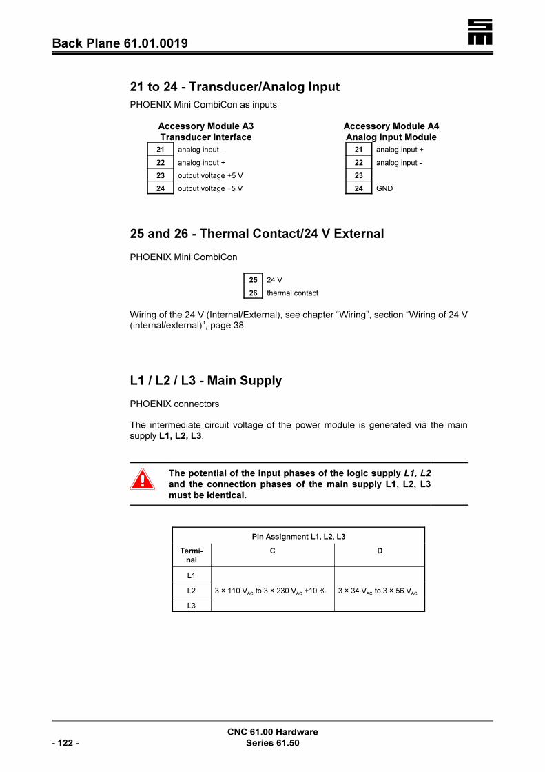
�Back Plane 61.01.0019
CNC 61.00 Hardware
- 122 - Series 61.50
21 to 24 - Transducer/Analog Input
PHOENIX Mini CombiCon as inputs
Accessory Module A3
Transducer Interface
21 analog input !
22 analog input +
23 output voltage +5 V
24 output voltage !5 V
Accessory Module A4
Analog Input Module
21 analog input +
22 analog input -
23
24 GND
25 and 26 - Thermal Contact/24 V External
PHOENIX Mini CombiCon
25 24 V
26 thermal contact
Wiring of the 24 V (Internal/External), see chapter “Wiring”, section “Wiring of 24 V(internal/external)”, page 38.
L1 / L2 / L3 - Main Supply
PHOENIX connectors
The intermediate circuit voltage of the power module is generated via the mainsupply L1, L2, L3.
�The potential of the input phases of the logic supply L1, L2
and the connection phases of the main supply L1, L2, L3
must be identical.
Pin Assignment L1, L2, L3
Termi-
nal
C D
L1
3 × 110 VAC to 3 × 230 VAC +10 % 3 × 34 VAC to 3 × 56 VACL2
L3

� Back Plane 61.01.0019
CNC 61.00 Hardware
Series 61.50 - 123 -
L1 / L2 - Mains Input for the Logic Supply
PHOENIX connectors or screw connectors
The logic supply generates a non mains-separated 30 V voltage supply independent-ly of the main supply. Therefore, the intra-system logic is ready for operation beforeturning on the main supply L1, L2, L3 and, the user has all signals and messagesprovided instantly.
Due to the respective wiring of L1, L2 the main supply (L1, L2, L3) must only beturned on, if the CNC module is to be activated (active regulator). See also the “Con-nection Diagrams“, starting on page 39.
�The wiring must be made in order to have the logic supply
turned on before the main supply.
Pin Assignment L1, L2
Termi-
nal
C D
L1 2 × 110 VAC +10 %to2 × 230 VAC +10 %
2 × 34 VAC to2 × 56 VACL2
�The mains input L1, L2 must always be connected. The an-
gle pulses and error messages are kept in case of EMER-
GENCY STOP situations. If the main supply is turned off,
make sure that all three mains phases are turned off conse-
quently! That is why a main conductor with positively driven
contacts must be used.
Rex - External Ballast Resistor
PHOENIX connector or screw connector
A ballast resistor (75 S / 5 W) is already provided on the back plane. If too muchenergy is to be changed into heat during the deceleration, an additional ballast resis-tor of 22 S / 220 W can be connected between the connectors +UB and R
EX. The
internal ballast resistor must not be removed.

�Back Plane 61.01.0028
CNC 61.00 Hardware
- 124 - Series 61.50
10.2.2 Back Plane 61.01.0028
Mounting as swing frame in a compact housing
X6 INTERBUS connection, page 128X5 INTERBUS connection, page 127
X1 Connection of first measuring system, page 125
X7 Fan connection
PE Earth conductor+UB Intermediate circuit voltage
L1 L2 Mains input for the logic supply
L1 L2 L3 Mains input for generating the intermediate circuit voltage
X2 Terminal connection, page 126
X19 Profibus connection, page 129
X9 MODLINK connection, page 128X10 MODLINK connection, page 129
X21 Serial interfaces 2 and 3, page 129
X4 Angle pulse connection, page 127
X8 Transducer connection, page 128
X3 I/O expansion, page 126
V U W Motor connection
Rex
External ballast resistor
PE Earth conductor
21 to 24 Thermal contact / 24 V external, page 131
X31 CAN bus connection, page 129
1 to 20 Logic signals, page 130
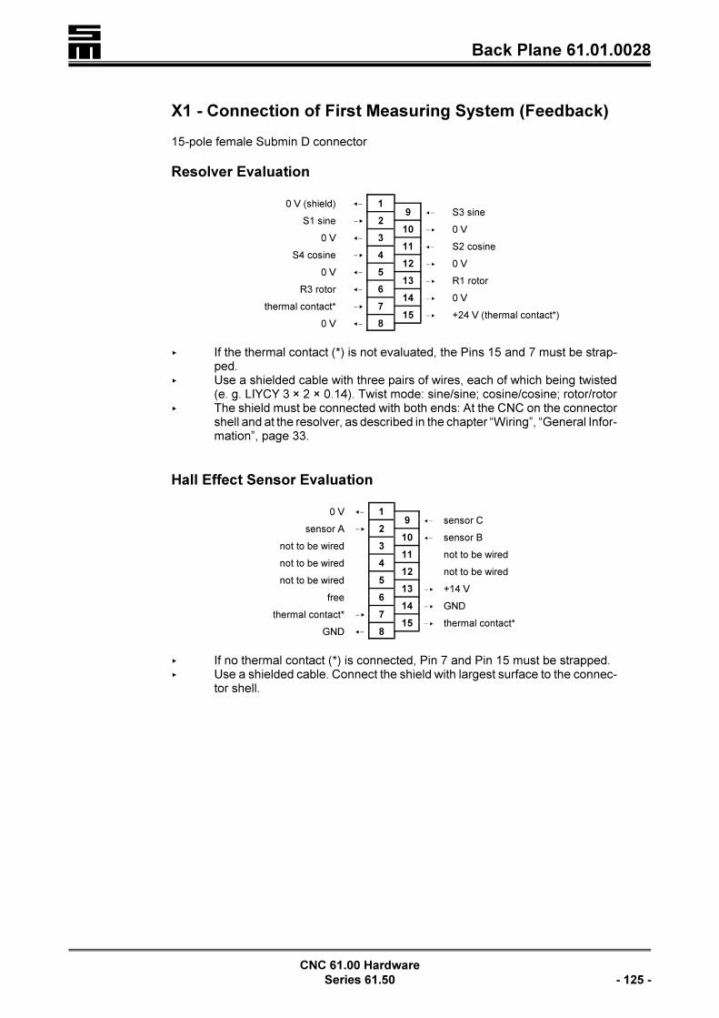
� Back Plane 61.01.0028
CNC 61.00 Hardware
Series 61.50 - 125 -
X1 - Connection of First Measuring System (Feedback)
15-pole female Submin D connector
Resolver Evaluation
0 V (shield) =! 19 =! S3 sine
S1 sine !< 210 !< 0 V
0 V =! 311 =! S2 cosine
S4 cosine !< 412 !< 0 V
0 V =! 513 !< R1 rotor
R3 rotor =! 614 !< 0 V
thermal contact* !< 715 !< +24 V (thermal contact*)
0 V =! 8
< If the thermal contact (*) is not evaluated, the Pins 15 and 7 must be strap-ped.
< Use a shielded cable with three pairs of wires, each of which being twisted(e. g. LIYCY 3 × 2 × 0.14). Twist mode: sine/sine; cosine/cosine; rotor/rotor
< The shield must be connected with both ends: At the CNC on the connectorshell and at the resolver, as described in the chapter “Wiring”, “General Infor-mation”, page 33.
Hall Effect Sensor Evaluation
0 V =! 19 =! sensor C
sensor A !< 210 =! sensor B
not to be wired 311 not to be wired
not to be wired 412 not to be wired
not to be wired 513 !< +14 V
free 614 !< GND
thermal contact* !< 715 !< thermal contact*
GND =! 8
< If no thermal contact (*) is connected, Pin 7 and Pin 15 must be strapped.< Use a shielded cable. Connect the shield with largest surface to the connec-
tor shell.
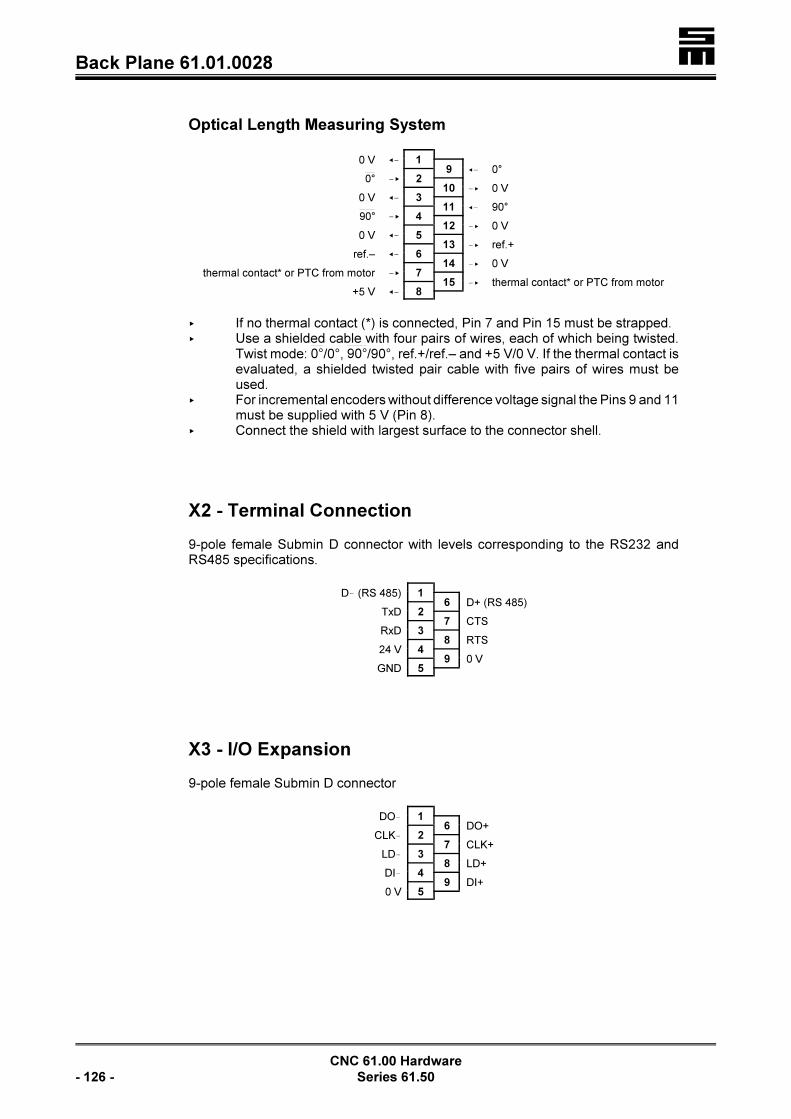
�Back Plane 61.01.0028
CNC 61.00 Hardware
- 126 - Series 61.50
Optical Length Measuring System
0 V =! 19 =! 0°
!< 20°10 !< 0 V
0 V =! 311 =! 90°
!< 490°12 !< 0 V
0 V =! 513 !< ref.+
ref.– =! 614 !< 0 V
thermal contact* or PTC from motor !< 715 !< thermal contact* or PTC from motor
+5 V =! 8
< If no thermal contact (*) is connected, Pin 7 and Pin 15 must be strapped.< Use a shielded cable with four pairs of wires, each of which being twisted.
Twist mode: /0°, /90°, ref.+/ref.– and +5 V/0 V. If the thermal contact is0° 90°evaluated, a shielded twisted pair cable with five pairs of wires must beused.
< For incremental encoders without difference voltage signal the Pins 9 and 11must be supplied with 5 V (Pin 8).
< Connect the shield with largest surface to the connector shell.
X2 - Terminal Connection
9-pole female Submin D connector with levels corresponding to the RS232 andRS485 specifications.
D! (RS 485) 16 D+ (RS 485)
TxD 27 CTS
RxD 38 RTS
24 V 49 0 V
GND 5
X3 - I/O Expansion
9-pole female Submin D connector
DO! 16 DO+
CLK! 27 CLK+
LD! 38 LD+
DI! 49 DI+
0 V 5
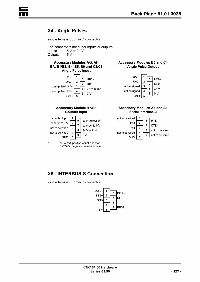
� Back Plane 61.01.0028
CNC 61.00 Hardware
Series 61.50 - 127 -
X4 - Angle Pulses
9-pole female Submin D connector
The connectors are either inputs or outputs.Inputs: 5 V or 24 VOutputs: 5 V
Accessory Modules AG, AH
BA, B1/B2, B4, B5, B9 and C2/C3
Angle Pulse Input
UA0+ 16 UB0+
UA0! 27 UB0!
zero pulse UN0+ 38 24 V output
zero pulse UN0! 49 0 V
GND 5
Accessory Modules B3 and C4
Angle Pulse Output
UA0+ 16 UB0+
UA0! 27 UB0!
not assigned 38 24 V
not assigned 49 0 V
GND 5
Accessory Module B7/B8
Counter Input
counter input 16 count direction*
connect to 0 V 27 connect to 0 V
not to be wired 38 24 V output
not to be wired 49 0 V
GND 5
* not wired: positive count direction5 V/24 V: negative count direction
Accessory Modules A5 and A6
Serial Interface 2
not to be wired 16 RTS
TxD 27 CTS
RxD 38 not to be wired
not to be wired 49 not to be wired
GND 5
X5 - INTERBUS-S Connection
9-pole female Submin D connector
DO 2+ 16 DO 2!
DI 2+ 27 DI 2!
GND 38
49 RBST
5 V 5

�Back Plane 61.01.0028
CNC 61.00 Hardware
- 128 - Series 61.50
X6 - INTERBUS-S Connection
9-pole male Submin D connector
DO 1+ 16 DO 1!
DI 1+ 27 DI 1!
GND 38
49
5
X8 - Transducer Connection
9-pole female Submin D connector
Accessory Modules A3, A5, AA and AE
Transducer Input
analog input - 16 analog input +
27
output voltage +5 V 38 output voltage !5 V
49 GND
5
Accessory Module AF
Active Transducer
analog input (±5 V) 16 calibrating signal
27
supply voltage +12 V 38 supply voltage !12 V
49 GND (shared ground)
5
X9 - MODLINK Connection
9-pole female Submin D connector
DO+ 16
DO! 27
38
GND 49
5

� Back Plane 61.01.0028
CNC 61.00 Hardware
Series 61.50 - 129 -
X10 - MODLINK Connection
9-pole male Submin D connector
DI+ 16
DI! 27
38
GND 49
5
X19 - Profibus-DP Connection
9-pole female Submin D connector
shield 16 VP
27
RxD/TxD-P 38 RxD/TxD-N
49
DGND 5
X21 - Serial Interfaces 2 and 3
9-pole female Submin D connector
TxD3 (transmission line serial interface 3) 16
TxD2 27 RTS2
RxD2 (receive line serial interface 2) 38 CTS2
RxD3 49
GND 5
X31 - CAN Bus Connection
9-pole female Submin D connector
16
CAN-L 27 CAN-H
GND 38
49 VCCCAN
5
VCCCAN: 8 V to 15 V

�Back Plane 61.01.0028
CNC 61.00 Hardware
- 130 - Series 61.50
U / V / W / PE - Motor Connections
< PHOENIX screw connectorsThe maximum conductor cross-section for the terminals is 2.5 mm².
1 to 20 - Logic Signals
PHOENIX Mini CombiCon
All inputs and outputs work with a level of 24 V. The total load of all outputs must notexceed 350 mA.
Please take into consideration that some inputs and outputs have alternating mea-ning. If, for example, the function “Motor Brake” has been activated in the parametereditor (IP_E_BRAKE=ON), the output o1 will automatically be identical with thefunction “Motor Brake”.
1 regulator OK+(voltage-free contacts)
2 regulator OK
3 output o0 (always regulator OK)
4 output o2
5 output o1 (= motor brake, if IP_E_BRAKE = ON)
6 output o7
7 output o6
8 output o5
9 output o4
10 output o3
11 input i2 (= limit switch–, if IP_E_END = ON)
12 input i1 (= limit switch+, if IP_E_END = ON)
13 input i3
14 input i0 (always emergency stop)
15 input i7
16 input i6
17 input i5
18 input i4
19 0 V*
20 24 V*
* see also the section “Wiring of the 24 V (Internal/External) in the chapter“Wiring”, page 38.
< Additional inputs and outputs can be connected to X3 via the I/O modules44.20.xxx. See also the chapter “External I/O Modules”, starting on page201.

� Back Plane 61.01.0028
CNC 61.00 Hardware
Series 61.50 - 131 -
21 to 24 - Thermal Contact/24 V External
PHOENIX Mini CombiCon
21 thermal contact
22 24 V internal
23 24 V external
24 0 V
Wiring of the 24 V (Internal/External), see chapter “Wiring”, section “Wiring of 24 V(internal/external)”, page 38.
L1 / L2 / L3 - Main Supply
PHOENIX connectorsThe intermediate circuit voltage of the power module is generated via the mainsupply L1, L2, L3.
�The potential of the input phases of the logic supply L1, L2
and the connection phases of the main supply L1, L2, L3
must be identical.
Pin Assignment L1, L2, L3
Termi-
nal
C D
L1
3 × 110 VAC to 3 × 230 VAC +10 % 3 × 34 VAC to 3 × 56 VACL2
L3
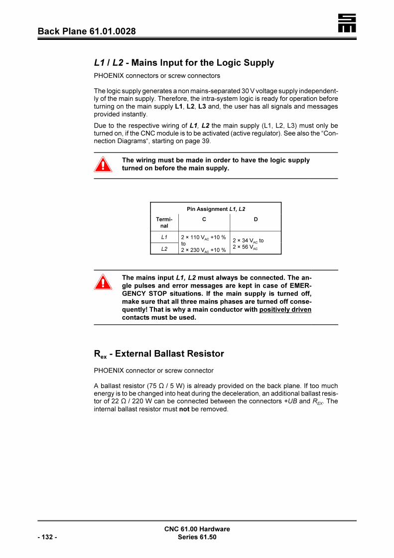
�Back Plane 61.01.0028
CNC 61.00 Hardware
- 132 - Series 61.50
L1 / L2 - Mains Input for the Logic Supply
PHOENIX connectors or screw connectors
The logic supply generates a non mains-separated 30 V voltage supply independent-ly of the main supply. Therefore, the intra-system logic is ready for operation beforeturning on the main supply L1, L2, L3 and, the user has all signals and messagesprovided instantly.
Due to the respective wiring of L1, L2 the main supply (L1, L2, L3) must only beturned on, if the CNC module is to be activated (active regulator). See also the “Con-nection Diagrams“, starting on page 39.
�The wiring must be made in order to have the logic supply
turned on before the main supply.
Pin Assignment L1, L2
Termi-
nal
C D
L1 2 × 110 VAC +10 %to2 × 230 VAC +10 %
2 × 34 VAC to2 × 56 VACL2
�The mains input L1, L2 must always be connected. The an-
gle pulses and error messages are kept in case of EMER-
GENCY STOP situations. If the main supply is turned off,
make sure that all three mains phases are turned off conse-
quently! That is why a main conductor with positively driven
contacts must be used.
Rex - External Ballast Resistor
PHOENIX connector or screw connector
A ballast resistor (75 S / 5 W) is already provided on the back plane. If too muchenergy is to be changed into heat during the deceleration, an additional ballast resis-tor of 22 S / 220 W can be connected between the connectors +UB and R
EX. The
internal ballast resistor must not be removed.

� Back Plane 61.01.0051
CNC 61.00 Hardware
Series 61.50 - 133 -
10.2.3 Back Plane 61.01.0051
Mounting as swing frame into a compact housing
X1 Connection of first measuring system, page 134
PE Earth conductor+UB Intermediate circuit voltage
L1 L2 Mains input for the logic supply
L1 L2 L3 Mains input for generating the intermediate circuit voltage
X19 Profibus connection, page 137
X2 Terminal connection, page 135
X7 Angle pulse connection, page 136
X100 Fan connection
X33 Ethernet connection, page 138
X21 Serial interfaces 2 and 3, page 137
X4 Angle pulse connection, page 136
X15 Transducer connection, page 137
X3 I/O expansion, page 135
V U W Motor connection
Rex
External ballast resistorPE Earth conductor!UB Intermediate circuit voltage
X31 CAN bus connection, page 138
21 to 24 Thermal contact / 24 V external, page 139
1 to 20 Logic signals, page 139

�Back Plane 61.01.0051
CNC 61.00 Hardware
- 134 - Series 61.50
X1 - Connection of First Measuring System (Feedback)
15-pole female Submin D connector
Resolver Evaluation
0 V =! 19 =! S3 sine
S1 sine !< 210 !< 0 V
0 V =! 311 =! S2 cosine
S4 cosine !< 412 !< 0 V
0 V =! 513 !< R1 rotor
R3 rotor =! 614 !< 0 V
thermal contact* !< 715 !< +24 V (thermal contact*)
0 V =! 8
< If the thermal contact (*) is not evaluated, the Pins 15 and 7 must be strapped.< Use a shielded cable with three pairs of wires, each of which being twisted (e. g.
LIYCY 3 × 2 × 0.14). Twist mode: sine/sine; cosine/cosine; rotor/rotor< The shield must be connected with both ends: At the CNC on the connector shell
and at the resolver, as described in the chapter “Wiring”, “General Information”,page 33.
Hall Effect Sensor Evaluation
0 V =! 19 =! sensor C
sensor A !< 210 =! sensor B
not to be wired 311 not to be wired
not to be wired 412 not to be wired
not to be wired 513 !< +14 V
free 614 !< GND
thermal contact* !< 715 !< thermal contact*
GND =! 8
< If no thermal contact (*) is connected, Pin 7 and Pin 15 must be strapped.< Use a shielded cable. Connect the shield with largest surface to the connector
shell.

� Back Plane 61.01.0051
CNC 61.00 Hardware
Series 61.50 - 135 -
Optical Length Measuring System
0 V =! 19 =! 0°
0° !< 210 !< 0 V
0 V =! 311 =! 90°
90° !< 412 !< 0 V
0 V =! 513 !< ref.+
ref.– =! 614 !< 0 V
thermal contact* or PTC from motor !< 715 !< thermal contact* or PTC from motor
+5 V =! 8
< If no thermal contact (*) is connected, Pin 7 and Pin 15 must be strapped.< Use a shielded cable with four pairs of wires, each of which being twisted.Twist
mode: /0°, /90°, ref.+/ref.– and +5 V/0 V. If the thermal contact is evaluated,0° 90°a shielded twisted pair cable with five pairs of wires must be used.
< For incremental encoders without difference voltage signal the Pins 9 and 11must be supplied with 5 V (Pin 8).
< Connect the shield with largest surface to the connector shell.
X2 - Terminal Connection
9-pole female Submin D connector with levels corresponding to the RS232 andRS485 specifications.
D! (RS 485) 16 D+ (RS 485)
TxD 27 CTS
RxD 38 RTS
24 V 49 0 V
GND 5
X3 - I/O Expansion
9-pole female Submin D connector
DO! 16 DO+
CLK! 27 CLK+
LD! 38 LD+
DI! 49 DI+
0 V 5

�Back Plane 61.01.0051
CNC 61.00 Hardware
- 136 - Series 61.50
X4 - Angle Pulses
9-pole female Submin D connector
The connectors are either inputs or outputs.Inputs: 5 V or 24 VOutputs: 5 V
Accessory Modules AG, AH
BA, B1/B2, B4, B5, B9 and C2/C3
Angle Pulse Input
UA0+ 16 UB0+
UA0! 27 UB0!
zero pulse UN0+ 38 24 V output
zero pulse UN0! 49 0 V
GND 5
Accessory Modules B3 and C4
Angle Pulse Output
UA0+ 16 UB0+
UA0! 27 UB0!
not assigned 38 24 V
not assigned 49 0 V
GND 5
Accessory Module B7/B8
Counter Input
counter input 16 count direction*
connect to 0 V 27 connect to 0 V
not to be wired 38 24 V output
not to be wired 49 0 V
GND 5
* not wired: positive count direction5 V/24 V: negative count direction
Accessory Modules A5 and A6
Serial Interface 2
not to be wired 16 RTS
TxD 27 CTS
RxD 38 not to be wired
not to be wired 49 not to be wired
GND 5
X7 - Angle Pulses
9-pole female Submin D connector
Accessory Modules
BA, B4, B7/B8
Angle Pulse Output
UA0+ 16 UB0+
UA0! 27 UB0!
free 38 24 V
free 49 0 V
0 V 5
Accessory Modules B5 and B9
Angle Pulse Input
UA0+ 16 UB0+
UA0! 27 UB0!
zero pulse UN0+ 38 24 V
zero pulse UN0! 49 0 V
0 V 5
Accessory Modules
C2/C3 and C4
SSI Interface
SSI clock+ 16 SSI data+
SSI clock! 27 SSI data!
free 38 24 V
free 49 0 V
0 V 5

� Back Plane 61.01.0051
CNC 61.00 Hardware
Series 61.50 - 137 -
X15 - Active/Passive Transducer
9-pole female Submin D connector
Accessory Module AG
analog input 1- 16 analog input 1+
analog input 2- 27 analog input 2+
output voltage +5 V 38 output voltage !5 V
49 GND
5
Accessory Module AH
analog input 1 16 calibrating signal 1
analog input 2 27 calibrating signal 2
supply voltage +12 V 38 supply voltage !12 V
49 GND
5
X19 - Profibus Connection
9-pole female Submin D connector
shield 16 VP
27
RxD/TxD-P 38 RxD/TxD-N
49
DGND 5
X21 - Serial Interfaces 2 and 3
9-pole female Submin D connector
TxD3 (transmission line serial interface 3) 16
TxD2 27 RTS2
RxD2 (receive line serial interface 2) 38 CTS2
RxD3 49
GND 5

�Back Plane 61.01.0051
CNC 61.00 Hardware
- 138 - Series 61.50
X31 - CAN Bus Connection
9-pole female Submin D connector
16
CAN-L 27 CAN-H
GND 38
49 VCCCAN
5
VCCCAN: 8 V to 15 V
X33 - Ethernet Connection
RJ45 female connector (Western)
Pin Designation
1 TX+
2 TX!
3 RX+
4 not connected
5 not connected
6 RX!
7 not connected
8 not connected
U / V / W - Motor Connections
< PHOENIX screw connectorsThe maximum conductor cross-section for the terminals is 2.5 mm².
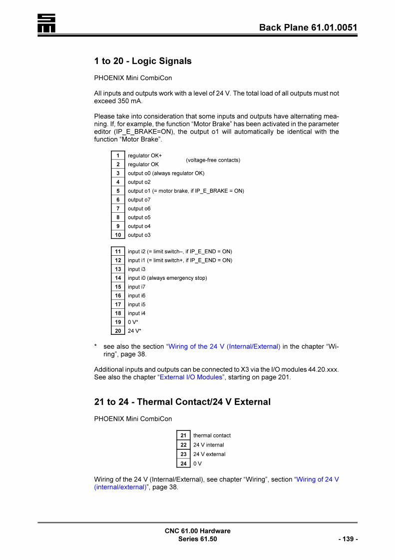
� Back Plane 61.01.0051
CNC 61.00 Hardware
Series 61.50 - 139 -
1 to 20 - Logic Signals
PHOENIX Mini CombiCon
All inputs and outputs work with a level of 24 V. The total load of all outputs must notexceed 350 mA.
Please take into consideration that some inputs and outputs have alternating mea-ning. If, for example, the function “Motor Brake” has been activated in the parametereditor (IP_E_BRAKE=ON), the output o1 will automatically be identical with thefunction “Motor Brake”.
1 regulator OK+(voltage-free contacts)
2 regulator OK
3 output o0 (always regulator OK)
4 output o2
5 output o1 (= motor brake, if IP_E_BRAKE = ON)
6 output o7
7 output o6
8 output o5
9 output o4
10 output o3
11 input i2 (= limit switch–, if IP_E_END = ON)
12 input i1 (= limit switch+, if IP_E_END = ON)
13 input i3
14 input i0 (always emergency stop)
15 input i7
16 input i6
17 input i5
18 input i4
19 0 V*
20 24 V*
* see also the section “Wiring of the 24 V (Internal/External) in the chapter “Wi-ring”, page 38.
Additional inputs and outputs can be connected to X3 via the I/O modules 44.20.xxx.See also the chapter “External I/O Modules”, starting on page 201.
21 to 24 - Thermal Contact/24 V External
PHOENIX Mini CombiCon
21 thermal contact
22 24 V internal
23 24 V external
24 0 V
Wiring of the 24 V (Internal/External), see chapter “Wiring”, section “Wiring of 24 V(internal/external)”, page 38.

�Back Plane 61.01.0051
CNC 61.00 Hardware
- 140 - Series 61.50
L1 / L2 / L3 - Main Supply
PHOENIX connectors
The intermediate circuit voltage of the power module is generated via the mainsupply L1, L2, L3.
�The potential of the input phases of the logic supply L1, L2
and the connection phases of the main supply L1, L2, L3
must be identical.
Pin Assignment L1, L2, L3
Termi-
nal
C D
L1
3 × 110 VAC to 3 × 230 VAC +10 % 3 × 34 VAC to 3 × 56 VACL2
L3
L1 / L2 - Mains Input for the Logic Supply
PHOENIX connectors or screw connectors
The logic supply generates a non mains-separated 30 V voltage supply independent-ly of the main supply. Therefore, the intra-system logic is ready for operation beforeturning on the main supply L1, L2, L3 and, the user has all signals and messagesprovided instantly.
Due to the respective wiring of L1, L2 the main supply (L1, L2, L3) must only beturned on, if the CNC module is to be activated (active regulator). See also the “Con-nection Diagrams“, starting on page 39.
�The wiring must be carried out that way that the logic supp-
ly is turned on before the main supply.
Pin Assignment L1, L2
Termi-
nal
C D
L1 2 × 110 VAC +10 %to2 × 230 VAC +10 %
2 × 34 VAC to2 × 56 VACL2
�The mains input L1, L2 must always be connected. The an-
gle pulses and error messages are kept in case of EMER-
GENCY STOP situations. If the main supply is turned off,
make sure that all three mains phases are turned off conse-
quently! That is why a main conductor with positively driven
contacts must be used.

� Back Plane 61.01.0051
CNC 61.00 Hardware
Series 61.50 - 141 -
�Back Plane 61.01.0051
CNC 61.00 Hardware
- 142 - Series 61.50
REX - External Ballast Resistor
PHOENIX connector or screw connector
A ballast resistor (75 S / 5 W) is already provided on the back plane. If too muchenergy is to be changed into heat during the deceleration, an additional ballast resis-tor of 22 S / 220 W can be connected between the connectors +UB and R
EX. The
internal ballast resistor must not be removed.

� Back Plane 61.01.0057
CNC 61.00 Hardware
Series 61.50 - 143 -
10.2.4 Back Plane 61.01.0057
Wall mounting into a compact housing
X7 Angle pulse connection, page 146X3 I/O expansion, page 145X2 Terminal connection, page 145X4 Angle pulse connection, page 146
PE Earth conductorL1 L2 L3 Mains input for generating the intermediate circuit voltage
X1 Connection of first measuring system, page 144
S1 Hook switch, page 147
X33 Ethernet connection, page 147
1 to 20 Logic signals, page 14821 to 24 Transducer/analog input, page 14925 and 26 24 V / thermal contact, page 149
X15 Transducer connection, page 147
X10 X 1
1
Fan connection
L1 L2 Mains input for the logic supply+UB Intermediate circuit voltageR
EXExternal ballast resistor
PE Earth conductor!UB Intermediate circuit voltageU V W Motor connection

�Back Plane 61.01.0057
CNC 61.00 Hardware
- 144 - Series 61.50
X1 - Connection of First Measuring System (Feedback)
15-pole female Submin D connector
Resolver Evaluation
0 V =! 19 =! S3 sine
S1 sine !< 210 !< 0 V
0 V =! 311 =! S2 cosine
S4 cosine !< 412 !< 0 V
0 V =! 513 !< R1 rotor
R3 rotor =! 614 !< 0 V
thermal contact* !< 715 !< +24 V (thermal contact*)
0 V =! 8
< If the thermal contact (*) is not evaluated, the Pins 15 and 7 must be strapped.< Use a shielded cable with three pairs of wires, each of which being twisted (e. g.
LIYCY 3 × 2 × 0.14). Twist mode: sine/sine; cosine/cosine; rotor/rotor< The shield must be connected with both ends: At the CNC on the connector shell
and at the resolver, as described in the chapter “Wiring”, “General Information”,page 33.
Hall Effect Sensor Evaluation
0 V =! 19 =! sensor C
sensor A !< 210 =! sensor B
not to be wired 311 not to be wired
not to be wired 412 not to be wired
not to be wired 513 !< +14 V
free 614 !< GND
thermal contact* !< 715 !< thermal contact*
GND =! 8
< If no thermal contact (*) is connected, Pin 7 and Pin 15 must be strapped.< Use a shielded cable. Connect the shield with largest surface to the connector
shell.

� Back Plane 61.01.0057
CNC 61.00 Hardware
Series 61.50 - 145 -
Optical Length Measuring System
0 V =! 19 =! 0°
0° !< 210 !< 0 V
0 V =! 311 =! 90°
90° !< 412 !< 0 V
0 V =! 513 !< ref.+
ref.– =! 614 !< 0 V
thermal contact* or PTC from motor !< 715 !< thermal contact* or PTC from motor
+5 V =! 8
< If no thermal contact (*) is connected, Pin 7 and Pin 15 must be strapped.< Use a shielded cable with four pairs of wires, each of which being twisted. Twist
mode: /0°, /90°, ref.+/ref.– and +5 V/0 V. If the thermal contact is evaluated,0° 90°a shielded twisted pair cable with five pairs of wires must be used.
< For incremental encoders without difference voltage signal the Pins 9 and 11must be supplied with 5 V (Pin 8).
< Connect the shield with largest surface to the connector shell.
X2 - Terminal Connection
9-pole female Submin D connector with levels corresponding to the RS232 andRS485 specifications.
D! (RS 485) 16 D+ (RS 485)
TxD 27 CTS
RxD 38 RTS
24 V 49 0 V
GND 5
X3 - I/O Expansion
9-pole female Submin D connector
DO! 16 DO+
CLK! 27 CLK+
LD! 38 LD+
DI! 49 DI+
0 V 5

�Back Plane 61.01.0057
CNC 61.00 Hardware
- 146 - Series 61.50
X4 - Angle Pulses
9-pole female Submin D connector
The connectors are either inputs or outputs.Inputs: 5 V or 24 VOutputs: 5 V
Accessory Modules AG, AH
BA, B1/B2, B4, B5, B9 and C2/C3
Angle Pulse Input
UA0+ 16 UB0+
UA0! 27 UB0!
zero pulse UN0+ 38 24 V output
zero pulse UN0! 49 0 V
GND 5
Accessory Modules B3 and C4
Angle Pulse Output
UA0+ 16 UB0+
UA0! 27 UB0!
not assigned 38 24 V
not assigned 49 0 V
GND 5
Accessory Module B7/B8
Counter Input
counter input 16 count direction*
connect to 0 V 27 connect to 0 V
not to be wired 38 24 V output
not to be wired 49 0 V
GND 5
* not wired: positive count direction5 V/24 V: negative count direction
Accessory Modules A5 and A6
Serial Interface 2
not to be wired 16 RTS
TxD 27 CTS
RxD 38 not to be wired
not to be wired 49 not to be wired
GND 5
X7 - Angle Pulses
9-pole female Submin D connector
Accessory Modules
BA, B4, B7/B8
Angle Pulse Output
UA0+ 16 UB0+
UA0! 27 UB0!
free 38 24 V
free 49 0 V
0 V 5
Accessory Modules B5 and B9
Angle Pulse Input
UA0+ 16 UB0+
UA0! 27 UB0!
zero pulse UN0+ 38 24 V
zero pulse UN0! 49 0 V
0 V 5
Accessory Modules
C2/C3 and C4
SSI Interface
SSI clock+ 16 SSI data+
SSI clock! 27 SSI data!
free 38 24 V
free 49 0 V
0 V 5

� Back Plane 61.01.0057
CNC 61.00 Hardware
Series 61.50 - 147 -
X15 - Active/Passive Transducer
9-pole female Submin D connector
Accessory Module AG
analog input 1- 16 analog input 1+
analog input 2- 27 analog input 2+
output voltage +5 V 38 output voltage !5 V
49 GND
5
Accessory Module AH
analog input 1 16 calibrating signal 1
analog input 2 27 calibrating signal 2
supply voltage +12 V 38 supply voltage !12 V
49 GND
5
X33 - Ethernet Connection
RJ45 female connector (Western)
Pin Designation
1 TX+
2 TX!
3 RX+
4 not connected
5 not connected
6 RX!
7 not connected
8 not connected
S1 - Hook Switch
Depending on the position of the hook switch S1 the CNC module provides the supp-ly voltage of 24 V.
S1 closed The CNC supplies the voltage at Pins 19 and 20 (default).S1 open The supply voltage is externally connected to Pins 19 and 20.
�An incorrect hooking of the switches can cause damage at
the CNC or the external power supply.
Wiring of the 24 V (internal/external), see chapter “Wiring”, section “Wiring of 24 V(internal/external)”, page 38.

�Back Plane 61.01.0057
CNC 61.00 Hardware
- 148 - Series 61.50
U / V / W - Motor Connection
< PHOENIX screw connectorsThe maximum conductor cross-section for the terminals is 2.5 mm².
1 to 20 - Logic Signals
PHOENIX Mini CombiCon
All inputs and outputs work with a level of 24 V. The total load of all outputs must notexceed 350 mA.
Please take into consideration that some inputs and outputs have alternating mea-ning. If, for example, the function “Motor Brake” has been activated in the parametereditor (IP_E_BRAKE=ON), the output o1 will automatically be identical with thefunction “Motor Brake”.
1 regulator OK+(voltage-free contacts)
2 regulator OK
3 output o0 (always regulator OK)
4 output o2
5 output o1 (= motor brake, if IP_E_BRAKE = ON)
6 output o7
7 output o6
8 output o5
9 output o4
10 output o3
11 input i2 (= limit switch–, if IP_E_END = ON)
12 input i1 (= limit switch+, if IP_E_END = ON)
13 input i3
14 input i0 (always emergency stop)
15 input i7
16 input i6
17 input i5
18 input i4
19 0 V*
20 24 V*
* see also the section “Wiring of the 24 V (Internal/External) in the chapter “Wi-ring”, page 38.
Additional inputs and outputs can be connected to X3 via the I/O modules 44.20.xxx.See also the chapter “External I/O Modules”, starting on page 201.

� Back Plane 61.01.0057
CNC 61.00 Hardware
Series 61.50 - 149 -
21 to 24 - Transducer/Analog Input
PHOENIX Mini CombiCon as inputs
Accessory Module A3 and A5
Transducer Interface
21 analog input !
22 analog input +
23 output voltage +5 V
24 output voltage !5 V
Accessory Module A4
Analog Input Module
21 analog input +
22 analog input -
23
24 GND
25 and 26 - Thermal Contact/24 V External
PHOENIX Mini CombiCon
25 24 V
26 thermal contact
Wiring of the 24 V (Internal/External), see chapter “Wiring”, section “Wiring of 24 V(internal/external)”, page 38.
L1 / L2 / L3 - Main Supply
PHOENIX connectors
The intermediate circuit voltage of the power module is generated via the mainsupply L1, L2, L3.
�The potential of the input phases of the logic supply L1, L2
and the connection phases of the main supply L1, L2, L3
must be identical.
Pin Assignment L1, L2, L3
Termi-
nal
C D
L1
3 × 110 VAC to 3 × 230 VAC +10 % 3 × 34 VAC to 3 × 56 VACL2
L3

�Back Plane 61.01.0057
CNC 61.00 Hardware
- 150 - Series 61.50
L1 / L2 - Mains Input for the Logic Supply
PHOENIX connectors or screw connectors
The logic supply generates a non mains-separated 30 V voltage supply independent-ly of the main supply. Therefore, the intra-system logic is ready for operation beforeturning on the main supply L1, L2, L3 and, the user has all signals and messagesprovided instantly.
Due to the respective wiring of L1, L2 the main supply (L1, L2, L3) must only beturned on, if the CNC module is to be activated (active regulator). See also the “Con-nection Diagrams“, starting on page 39.
�The wiring must be carried out that way that the logic supp-
ly is turned on before the main supply.
Pin Assignment L1, L2
Termi-
nal
C D
L1 2 × 110 VAC +10 %to2 × 230 VAC +10 %
2 × 34 VAC to2 × 56 VACL2
�The mains input L1, L2 must always be connected. The an-
gle pulses and error messages are kept in case of EMER-
GENCY STOP situations. If the main supply is turned off,
make sure that all three mains phases are turned off conse-
quently! That is why a main conductor with positively driven
contacts must be used.
REX - External Ballast Resistor
PHOENIX connector or screw connector
A ballast resistor (75 S / 5 W) is already provided on the back plane. If too muchenergy is to be changed into heat during the deceleration, an additional ballast resis-tor of 22 S / 220 W can be connected between the connectors +UB and R
EX. The
internal ballast resistor must not be removed.

� Back Plane 61.01.0017
CNC 61.00 Hardware
Series 61.50 - 151 -
10.3 Back Planes of the Power Module 26.50.65
The power module 26.50.65 replaces the power module 26.50.42 and is fullydownward compatible. It may be used in existing systems.
LThe power module 26.50.42, however, is not generally upwardcompatible, since the compatibility depends on the wiring of thesystem. If necessary, contact SIEB & MEYER.
10.3.1 Back Plane 61.01.0017
Mounting into a 19” rack as hinged-frame unit and protection against touching
+UB Intermediate circuit voltage
Rex
External ballast resistor, page 154
X12 BB - volt-free contact “ready for operation”, page 153POK - volt-free contact “power OK”, page 153
Bus Internal connection, page 154
PE Earth conductor
L1 L2 L3 Mains input for generating the intermediate circuit voltage, page 152
L1 L2 Mains input for the logic supply, page 152
!UB Intermediate circuit voltage

�Back Plane 61.01.0017
CNC 61.00 Hardware
- 152 - Series 61.50
L1 / L2 / L3 - Main Supply
PHOENIX connectors
The intermediate circuit voltage of the power module is generated via the mainsupply L1, L2, L3.
�Connecting the main supply with three phases is indispen-
sable!
The potential of the input phases of the logic supply L1, L2
and the connection phases of the main supply L1, L2, L3
must be identical.
Screw Terminal
Voltage Range
B C / CZ* H I K
L13 × 70 VAC
+10 % –20%
3 × 230 VAC
+10 % –20%
3 × 380 VAC –5 %to3 × 480 VAC +10 %
3 × 280 VAC
+10 % –20%
3 × 250 VAC
+10 % –20%
L2
L3
* CZ: Power module without overvoltage protection
LThe power module should be protected with 16 A fuses with fastblow behavior (e.g. Siemens Silized 16 A/5SD420)!
�The time of discharging the intermediate circuit may be up
to 5 minutes after turning off the mains inputs, when the
power module is faulty (worst case). Usually, the interme-
diate circuit is discharged after approx. 2 s.
The contactor for the mains supply must not step back with
time lag in case of a fault. It must be considered that the
main contactor will not execute the time lag for deactivating
the CNC module in an EMERGENCY STOP situation.
L1 / L2 - Mains Input for the Logic Supply
PHOENIX connectors or screw connectors
Independently of the main supply, the logic supply generates a non mains-separa-
ted 30 V voltage supply that may be loaded up to 150 W (power modules with thecode letter B: 100 W). Therefore, the intra-system logic is ready for operation beforeturning on the main supply L1, L2, L3 and, the user has all signals and messagesprovided instantly.

� Back Plane 61.01.0017
CNC 61.00 Hardware
Series 61.50 - 153 -
Due to the respective wiring of L1, L2 the main supply (L1, L2, L3) must only beturned on, if the CNC module is to be activated (active regulator). See also the “Con-nection Diagrams“, starting on page 39.
�The wiring must be carried out that way that the logic supp-
ly is turned on before the main supply.
Screw Terminal
Voltage Range
B C / CZ* H I K
l1 2 × 70 VAC
+10 % –20%
2 × 230 VAC
+10 % –20%
2 × 380 VAC –5 %to2 × 480 VAC +10 %
2 × 280 VAC
+10 % –20%
2 × 250 VAC
+10 % –20%l2
* CZ: Power module without overvoltage protection
�The mains input L1, L2 must always be connected. The an-
gle pulses and error messages are kept in case of EMER-
GENCY STOP situations. If the main supply is turned off,
make sure that all three mains phases are turned off conse-
quently! That is why a main conductor with positively driven
contacts must be used.
X12 - POK and BB
PHOENIX Mini CombiCon or screw connectors
The volt-free contact POK closes, when the logic supply is provided at l1, l2 and, thepower module cannot detect any fault during an internal check. The contactor forenabling the main supply should be switched via these contacts.
Pins Assignment of POK
Screw Terminal Assignment
POK 24 V, 2 A
POK
The volt-free contact BB closes, when the power module is completely ready foroperation. Condition:< The logic supply at L1, L2 and< the main supply at L1, L2, L3 are provided.< No error message of the power module.
Pin Assignment BB
Screw Terminal Assignment
B 24 V, 2 A

�Back Plane 61.01.0017
CNC 61.00 Hardware
- 154 - Series 61.50
B
Rex - External Ballast Resistor
PHOENIX connector or screw terminal
An external ballast resistor can be connected between this connector and the con-nector +UB.
During the generator operation the motor feeds energy back into the intermediatecircuit. If the intermediate circuit voltage has reached a specific potential, the ballastresistor will be switched into the intermediate circuit via a transistor to dissipate thesurplus energy.
Screw Terminal Assignment
B C / CZ* H I K
Rext
5 S 5 S 10 S 10 S 5.6 S
+UB
* CZ: Power module without overvoltage protection
The values of the ballast resistors listed in the table are minimum values. The valueof the resistor to be used must not fall below the minimum value.
Bus - Internal Connection
The 12-pole bus line connects the power module and up to six CNC rack modules.The bus supplies the CNC modules with the voltage of +30 V (bus voltage). Addi-tionally, statuses of the power module (readiness for operation, malfunctions) aresignaled to the CNC 61.00 modules. At the power module the bus pins are outputs,whereas at the CNC module the bus pins are inputs.
The bus moreover provides the volt-free +5 V/GND that can be loaded with up to 1.8A. The potentiometer +5 V MSY at the front panel enables the precise adjustment ofthe 5 V.
Pin Assignment
1 +5 V
2 GND
3 + 4 earth potential
5 mains OK = +24 V
6 overvoltage message
7 +24 V
8 not assigned
9 + 10 +30 V � mains potential
11 + 12 0 V for the 30 V � mains potential

� Back Plane 61.01.0017
CNC 61.00 Hardware
Series 61.50 - 155 -
�Do not use the +30 V for any other purposes!

�Back Plane 61.01.0061
CNC 61.00 Hardware
- 156 - Series 61.50
Mains OKThis output intra-system activates and deactivates, inter alia, the CNC modules. Ifthe main supply is not provided, the signal “mains OK” will be LOW and the CNCmodules cannot be activated. The user may use this signal via the contacts BB.
Overvoltage MessageIf an overvoltage comes up, the level of 24 V bounces to 0 V. Then the regulator inthe CNC module is deactivated (POK and the main contactor open). Error messa-ges, however, are kept.
10.3.2 Back Plane 61.01.0061
Mounting into a 19” rack as hinged-frame unit
+UB Intermediate circuit voltage
Rex
External ballast resistor, page 159
X12 BB - volt-free contact “ready for operation”, page 158POK - volt-free contact “Power OK”, page 158
Bus Interne connection, page 159
PE Earth conductor
L1 L2 L3 Mains input for generating the intermediate circuit voltage, page 157
PE Earth conductorN Neutral conductor*, page 159
L1 L2 Mains input for the logic supply, page 157
!UB Intermediate circuit voltage
* If a residual current operating device is used, the screw connectors PE and Nmust be wired separately. If no residual current operating device is used, bothconnectors can be wired to earth together.

� Back Plane 61.01.0061
CNC 61.00 Hardware
Series 61.50 - 157 -
L1 / L2 / L3 - Main Supply
PHOENIX connectors
The intermediate circuit voltage of the power module is generated via the mainsupply L1, L2, L3.
�Connecting the main supply with three phases is indispen-
sable!
The potential of the input phases of the logic supply L1, L2
and the connection phases of the main supply L1, L2, L3
must be identical.
Screw Terminal
Voltage Range
B C / CZ* H I K
L13 × 70 VAC
+10 % –20%
3 × 230 VAC
+10 % –20%
3 × 380 VAC –5 %to3 × 480 VAC +10 %
3 × 280 VAC
+10 % –20%
3 × 250 VAC
+10 % –20%
L2
L3
* CZ: Power module without overvoltage protection
LThe power module should be protected with 16 A fuses with
fast blow behavior (e.g. Siemens Silized 16 A/5SD420)!
�The time of discharging the intermediate circuit may be up
to 5 minutes after turning off the mains inputs, when the
power module is faulty (worst case). Usually, the interme-
diate circuit is discharged after approx. 2 s.
The contactor for the mains supply must not step back with
time lag in case of a fault. Pay attention of the main contac-
tor not to execute the time lag for deactivating the CNC mo-
dule in an EMERGENCY STOP situation.
L1 / L2 - Mains Input for the Logic Supply
PHOENIX connectors or screw connectors
Independently of the main supply, the logic supply generates a non mains-separa-
ted 30 V voltage supply that may be loaded up to 150 W (power modules with thecode letter B: 100 W). Therefore, the intra-system logic is ready for operation beforeturning on the main supply L1, L2, L3 and, the user has all signals and messagesprovided instantly.
Due to the respective wiring of L1, L2 the main supply (L1, L2, L3) must only beturned on, if the CNC module is to be activated (active regulator). See also the “Con-nection Diagrams“, starting on page 39.

�Back Plane 61.01.0061
CNC 61.00 Hardware
- 158 - Series 61.50
�The wiring must be carried out that way that the logic supp-
ly is turned on before the main supply.
Screw Terminal
Voltage Range
B C / CZ* H I K
l1 2 × 70 VAC
+10 % –20%
2 × 230 VAC
+10 % –20%
2 × 380 VAC –5 %to2 × 480 VAC +10 %
2 × 280 VAC
+10 % –20%
2 × 250 VAC
+10 % –20%l2
* CZ: Power module without overvoltage protection
�The mains input L1, L2 must always be connected. The an-
gle pulses and error messages are kept in case of EMER-
GENCY STOP situations. If the main supply is turned off,
make sure that all three mains phases are turned off conse-
quently! That is why a main conductor with positively driven
contacts must be used.
X12 - POK and BB
PHOENIX Mini CombiCon or screw connectors
The volt-free contact POK closes, when the logic supply is provided at l1, l2 and, thepower module cannot detect any fault during an internal check. The contactor forenabling the main supply should be switched via these contacts.
Pins Assignment of POK
Screw Terminal Assignment
POK 24 V, 2 A
POK
The volt-free contact BB closes, when the power module is completely ready foroperation. Condition:< The logic supply at L1, L2 and< the main supply at L1, L2, L3 are provided.< No error message of the power module.
Pin Assignment BB
Screw Terminal Assignment
B 24 V, 2 A
B

� Back Plane 61.01.0061
CNC 61.00 Hardware
Series 61.50 - 159 -
REX - External Ballast Resistor
PHOENIX connector or screw connector
An external ballast resistor can be connected between this connector and the con-nector +UB.
During the generator operation the motor feeds energy back into the intermediatecircuit. If the intermediate circuit voltage has reached a specific potential, the ballastresistor will be switched into the intermediate circuit via a transistor to dissipate thesurplus energy.
Screw Terminal Assignment
B C / CZ* H I K
Rext
5 S 5 S 10 S 10 S 5.6 S
+UB
* CZ: Power module without overvoltage protection
The values of the ballast resistors listed in the table are minimum values. The valueof the resistor to be used must not fall below the minimum value.
N
If a residual current operating device is used in the system, the zero conductor mustbe connected to the screw connector N.
Bus - Internal Connection
The 12-pole bus line connects the power module and up to six CNC rack modules.The bus supplies the CNC modules with the voltage of +30 V (bus voltage). Addi-tionally, statuses of the power module (readiness for operation, malfunctions) aresignaled to the CNC 61.00 modules. At the power module the bus pins are outputs,whereas at the CNC module the bus pins are inputs.
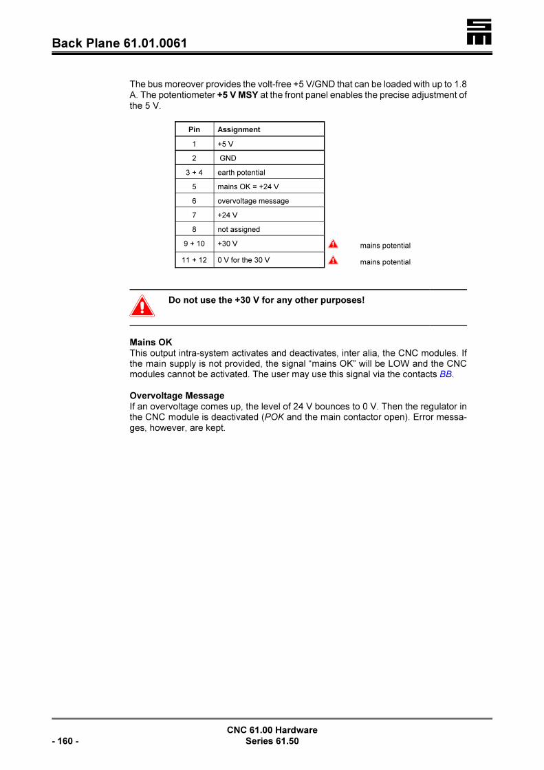
�Back Plane 61.01.0061
CNC 61.00 Hardware
- 160 - Series 61.50
The bus moreover provides the volt-free +5 V/GND that can be loaded with up to 1.8A. The potentiometer +5 V MSY at the front panel enables the precise adjustment ofthe 5 V.
Pin Assignment
1 +5 V
2 GND
3 + 4 earth potential
5 mains OK = +24 V
6 overvoltage message
7 +24 V
8 not assigned
9 + 10 +30 V � mains potential
11 + 12 0 V for the 30 V � mains potential
�Do not use the +30 V for any other purposes!
Mains OKThis output intra-system activates and deactivates, inter alia, the CNC modules. Ifthe main supply is not provided, the signal “mains OK” will be LOW and the CNCmodules cannot be activated. The user may use this signal via the contacts BB.
Overvoltage MessageIf an overvoltage comes up, the level of 24 V bounces to 0 V. Then the regulator inthe CNC module is deactivated (POK and the main contactor open). Error messa-ges, however, are kept.

� Back Plane 26.50.0078
CNC 61.00 Hardware
Series 61.50 - 161 -
10.3.3 Back Plane 26.50.0078
Mounting into a 19” rack as wall-mounting unit
8-pole screw terminal strip (the max. conductor cross-section for the terminals is4 mm²):
BB Volt-free contact “ready for operation”, page 163
POK Volt-free contact “Power OK”, page 163
+UB Intermediate circuit voltage (+)
Rext
Connection for an external ballast resistor, page 164
+UB Intermediate circuit voltage (rear side of back plane)
Bus Internal connection (rear side of back plane), page 164
!UB Intermediate circuit voltage (rear side of back plane)
� Earth conductor*
7-pole screw terminal strip (the max. conductor cross-section for the terminals is4mm²):
N Neutral conductor*, page 164
� Earth conductor
L1 L
2
Mains inputs for the logic supply, page 162
L1 L
2
L
3
Mains input for the main voltage supply, page 162

�Back Plane 26.50.0078
CNC 61.00 Hardware
- 162 - Series 61.50
* If a residual current operating device is used, the screw connectors � and Nmust be wired separately. If no residual current operating device is used, bothconnectors can be wired to earth together.
L1 / L2 / L3 - Main Supply
PHOENIX connectors
The intermediate circuit voltage of the power module is generated via the mainsupply L1, L2, L3.
�Connecting the main supply with three phases is indispen-
sable!
The potential of the input phases of the logic supply L1, L2
and the connection phases of the main supply L1, L2, L3
must be identical.
Screw Terminal
Voltage Range
B C / CZ* H I K
L13 × 70 VAC
+10 % –20%
3 × 230 VAC
+10 % –20%
3 × 380 VAC –5 %to3 × 480 VAC +10 %
3 × 280 VAC
+10 % –20%
3 × 250 VAC
+10 % –20%
L2
L3
* CZ: Power module without overvoltage protection
LThe power module should be protected with 16 A fuses with fastblow behavior (e.g. Siemens Silized 16 A/5SD420)!
�The time of discharging the intermediate circuit may be up
to 5 minutes after turning off the mains inputs, when the
power module is faulty (worst case). Usually, the interme-
diate circuit is discharged after approx. 2 s.
The contactor for the mains supply must not step back with
time lag in case of a fault. Pay attention of the main contac-
tor not to execute the time lag for deactivating the CNC mo-
dule in an EMERGENCY STOP situation.
L1 / L2 - Mains Input for the Logic Supply
PHOENIX connectors or screw connectors
Independently of the main supply, the logic supply generates a non mains-separa-
ted 30 V voltage supply that may be loaded up to 150 W (power modules with thecode letter B: 100 W). Therefore, the intra-system logic is ready for operation beforeturning on the main supply L1, L2, L3 and, the user has all signals and messagesprovided instantly.

� Back Plane 26.50.0078
CNC 61.00 Hardware
Series 61.50 - 163 -
Due to the respective wiring of L1, L2 the main supply (L1, L2, L3) must only beturned on, if the CNC module is to be activated (active regulator). See also the “Con-nection Diagrams“, starting on page 39.
�The wiring must be carried out that way that the logic supp-
ly is turned on before the main supply.
Screw Terminal
Voltage Range
B C / CZ* H I K
l1 2 × 70 VAC
+10 % –20%
2 × 230 VAC
+10 % –20%
2 × 380 VAC –5 %to2 × 480 VAC +10 %
2 × 280 VAC
+10 % –20%
2 × 250 VAC
+10 % –20%l2
* CZ: Power module without overvoltage protection
�The mains input L1, L2 must always be connected. The an-
gle pulses and error messages are kept in case of EMER-
GENCY STOP situations. If the main supply is turned off,
make sure that all three mains phases are turned off conse-
quently! That is why a main conductor with positively driven
contacts must be used.
POK and BB
PHOENIX Mini CombiCon or screw connectors
The volt-free contact POK closes, when the logic supply is provided at l1, l2 and, thepower module cannot detect any fault during an internal check. The contactor forenabling the main supply should be switched via these contacts.
Pins Assignment of POK
Screw Terminal Assignment
POK 24 V, 2 A
POK
The volt-free contact BB closes, when the power module is completely ready foroperation. Condition:< The logic supply at L1, L2 and< the main supply at L1, L2, L3 are provided.< No error message of the power module.
Pin Assignment BB
Screw Terminal Assignment
B 24 V, 2 A

�Back Plane 26.50.0078
CNC 61.00 Hardware
- 164 - Series 61.50
B
REX - External Ballast Resistor
PHOENIX connector or screw connector
An external ballast resistor can be connected between this connector and the con-nector +UB.
During the generator operation the motor feeds energy back into the intermediatecircuit. If the intermediate circuit voltage has reached a specific potential, the ballastresistor will be switched into the intermediate circuit via a transistor to dissipate thesurplus energy.
Screw Terminal Assignment
B C / CZ* H I K
Rext
5 S 5 S 10 S 10 S 5.6 S
+UB
* CZ: Power module without overvoltage protection
The values of the ballast resistors listed in the table are minimum values. The valueof the resistor to be used must not fall below the minimum value.
N
If a residual current operating device is used in the system, the zero conductor mustbe connected to the screw connector N.
Bus - Internal Connection
The 10-pole bus line connects the power module and up to six CNC rack modules.The bus supplies the CNC modules with the voltage of +30 V (bus voltage). Addi-tionally, statuses of the power module (readiness for operation, malfunctions) aresignaled to the CNC 61.00 modules. At the power module the bus pins are outputs,whereas at the CNC module the bus pins are inputs.
Pin Assignment
1 + 2 ground potential
3 mains OK = +24 V
4overvoltage message:
0 V in case of an error24 V without error
5 +24 V
6 not assigned
7 + 8 +30 V � mains potential
9 + 10 0 V for the 30 V � mains potential

� Back Plane 26.50.0078
CNC 61.00 Hardware
Series 61.50 - 165 -
�Do not use the +30 V for any other purposes!
Mains OKThis output intra-system activates and deactivates, inter alia, the CNC modules. Ifthe main supply is not provided, the signal “mains OK” will be LOW and the CNCmodules cannot be activated. The user may use this signal via the contacts BB.
Overvoltage MessageIf an overvoltage comes up, the level of 24 V bounces to 0 V. Then the regulator inthe CNC module is deactivated (POK and the main contactor open). Error messa-ges, however, are kept.

�Back Plane 26.50.0078
CNC 61.00 Hardware
- 166 - Series 61.50
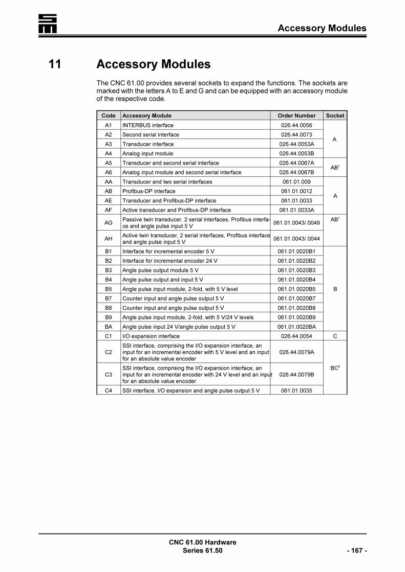
� Accessory Modules
CNC 61.00 Hardware
Series 61.50 - 167 -
11 Accessory Modules
The CNC 61.00 provides several sockets to expand the functions. The sockets aremarked with the letters A to E and G and can be equipped with an accessory moduleof the respective code.
Code Accessory Module Order Number Socket
A1 INTERBUS interface 026.44.0056
A A2 Second serial interface 026.44.0073
A3 Transducer interface 026.44.0053A
A4 Analog input module 026.44.0053B
A5 Transducer and second serial interface 026.44.0067AAB1
A6 Analog input module and second serial interface 026.44.0067B
AA Transducer and two serial interfaces 061.01.009
AAB Profibus-DP interface 061.01.0012
AE Transducer and Profibus-DP interface 061.01.0033
AF Active transducer and Profibus-DP interface 061.01.0033A
AGPassive twin transducer, 2 serial interfaces, Profibus interfa-ce and angle pulse input 5 V
061.01.0043/.0049AB1
AHActive twin transducer, 2 serial interfaces, Profibus interfaceand angle pulse input 5 V
061.01.0043/.0044
B1 Interface for incremental encoder 5 V 061.01.0020B1
B
B2 Interface for incremental encoder 24 V 061.01.0020B2
B3 Angle pulse output module 5 V 061.01.0020B3
B4 Angle pulse output and input 5 V 061.01.0020B4
B5 Angle pulse input module, 2-fold, with 5 V level 061.01.0020B5
B7 Counter input and angle pulse output 5 V 061.01.0020B7
B8 Counter input and angle pulse output 5 V 061.01.0020B8
B9 Angle pulse input module, 2-fold, with 5 V/24 V levels 061.01.0020B9
BA Angle pulse input 24 V/angle pulse output 5 V 061.01.0020BA
C1 I/O expansion interface 026.44.0054 C
C2SSI interface, comprising the I/O expansion interface, aninput for an incremental encoder with 5 V level and an inputfor an absolute value encoder
026.44.0079A
BC2
C3SSI interface, comprising the I/O expansion interface, aninput for an incremental encoder with 24 V level and an inputfor an absolute value encoder
026.44.0079B
C4 SSI interface, I/O expansion and angle pulse output 5 V 061.01.0035

�Accessory Modules
Code Accessory Module Order Number Socket
CNC 61.00 Hardware
- 168 - Series 61.50
Mother Board 026.44.0041 with Sockets for the Accessory Modules A to G
(Accessory Module F is located below accessory module G)
D1 CAN Bus interface 026.44.0055 D
E1 battery-buffered RAM and real time clock 026.44.0065 E
F1 MODLINK interface F3
G1 ETHERNET interface 061.01.0042 G3
1
The accessory modules occupy the sockets A and B and therefore cannot becombined with modules of code B.
2
The accessory modules occupy the sockets B and C and therefore cannot becombined with modules of code B.
3
The accessory modules F1 and G1 cannot be used simultaneously.
11.1 Mounting of the Accessory Modules
The mother board 026.44.0041 of the CNC 61.00 provides two 64-pole female con-nectors for expansions. The position of the modules can be found from the labeledletters. All accessory modules are mounted with the yellow marked side to the frontpanel (exception: accessory module F1).
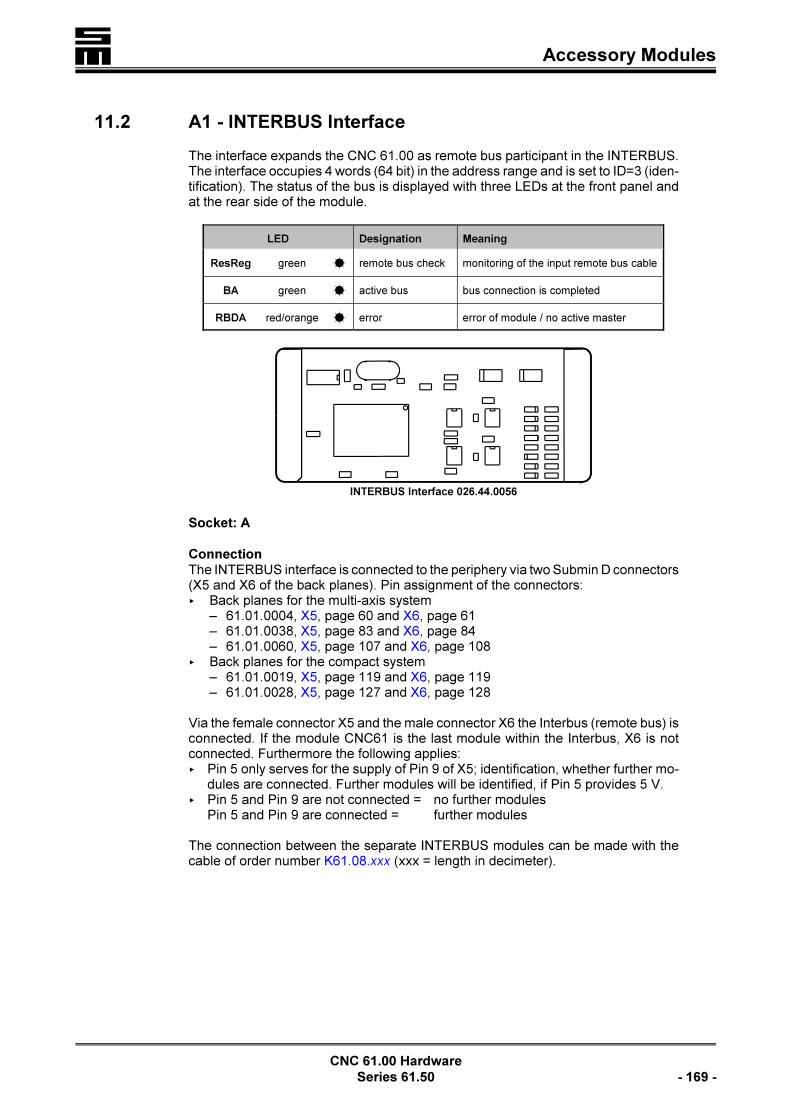
� Accessory Modules
CNC 61.00 Hardware
Series 61.50 - 169 -
INTERBUS Interface 026.44.0056
11.2 A1 - INTERBUS Interface
The interface expands the CNC 61.00 as remote bus participant in the INTERBUS.The interface occupies 4 words (64 bit) in the address range and is set to ID=3 (iden-tification). The status of the bus is displayed with three LEDs at the front panel andat the rear side of the module.
LED Designation Meaning
ResReg green � remote bus check monitoring of the input remote bus cable
BA green � active bus bus connection is completed
RBDA red/orange � error error of module / no active master
Socket: A
ConnectionThe INTERBUS interface is connected to the periphery via two Submin D connectors(X5 and X6 of the back planes). Pin assignment of the connectors:< Back planes for the multi-axis system
– 61.01.0004, X5, page 60 and X6, page 61– 61.01.0038, X5, page 83 and X6, page 84– 61.01.0060, X5, page 107 and X6, page 108
< Back planes for the compact system– 61.01.0019, X5, page 119 and X6, page 119– 61.01.0028, X5, page 127 and X6, page 128
Via the female connector X5 and the male connector X6 the Interbus (remote bus) isconnected. If the module CNC61 is the last module within the Interbus, X6 is notconnected. Furthermore the following applies:< Pin 5 only serves for the supply of Pin 9 of X5; identification, whether further mo-
dules are connected. Further modules will be identified, if Pin 5 provides 5 V.< Pin 5 and Pin 9 are not connected = no further modules
Pin 5 and Pin 9 are connected = further modules
The connection between the separate INTERBUS modules can be made with thecable of order number K61.08.xxx (xxx = length in decimeter).

�Accessory Modules
CNC 61.00 Hardware
- 170 - Series 61.50
Solder Side of the Interface
Second Serial Interface 026.44.0073
The ID code 3 (digital input/output module) is set as a standard for the interface.
Software (Example)The 4 words of the INTERBUS (64 bit) are inserted like an I/O expansion into theinput/output range. They assign the inputs or outputs 168 to 231.
SET 1, 0168; set the first bit in the Interbus
11.3 A2 - Second Serial Interface
The module provides an additional serial interface with a level corresponding toRS232. The interface may, for example, be used for connecting a serial printer.
Socket: A
ConnectionConnection of the module with the periphery via the 9-pole female Submin D con-nector X21< of the back plane 61.01.0028, page 129< of the back plane 61.01.0037, page 78< of the back plane 61.01.0051, page 137< of the back plane 61.01.0058, page 101
11.4 A3 - Transducer Interface
A transducer serves for measuring torques (e. g. for nut running applications) bymeans of resistance bridges. The impressing of a voltage at the transducer permitsto convert a torque into an equivalent voltage. The voltage is amplified and smoot-hed in the module and converted with an analog/digital converter.
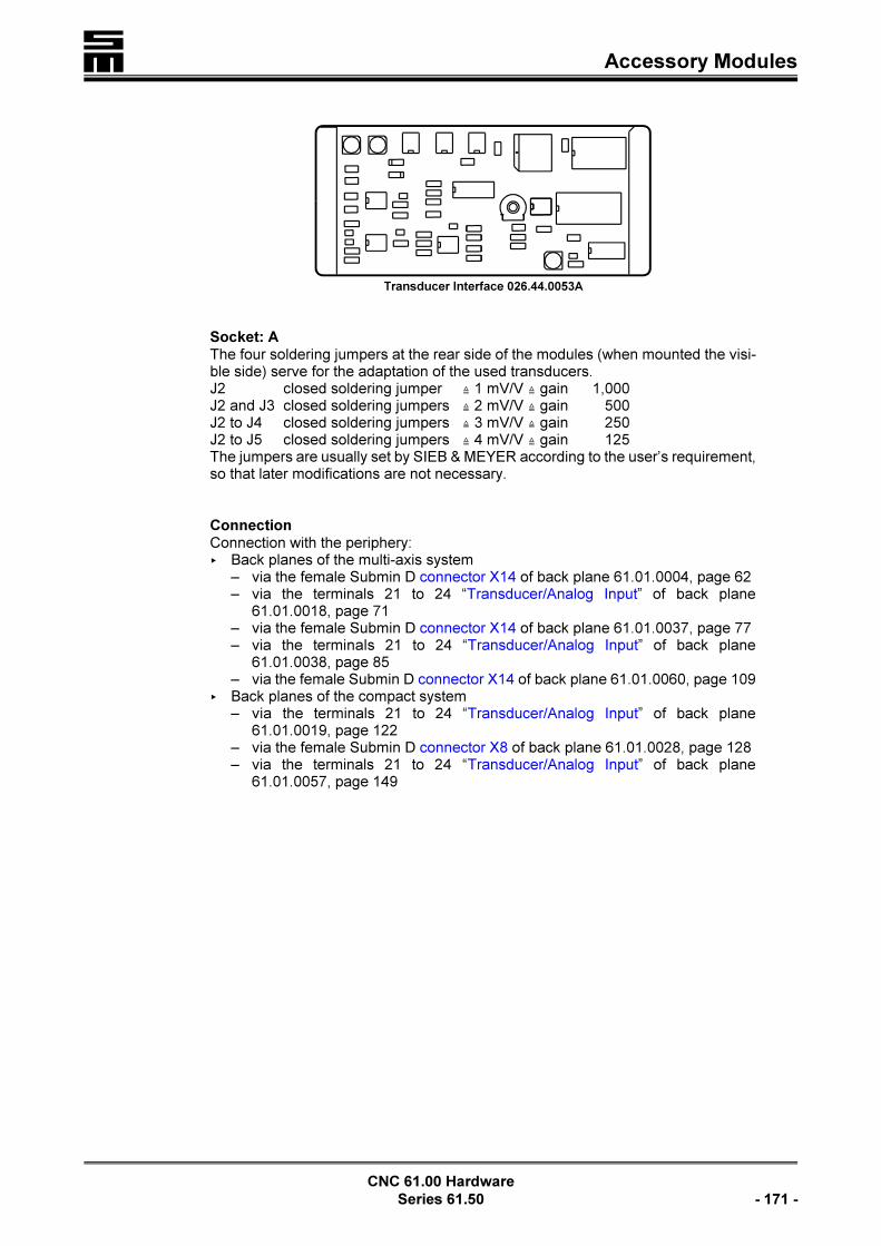
� Accessory Modules
CNC 61.00 Hardware
Series 61.50 - 171 -
Transducer Interface 026.44.0053A
Socket: AThe four soldering jumpers at the rear side of the modules (when mounted the visi-ble side) serve for the adaptation of the used transducers.J2 closed soldering jumper × 1 mV/V × gain 1,000J2 and J3 closed soldering jumpers × 2 mV/V × gain 500J2 to J4 closed soldering jumpers × 3 mV/V × gain 250J2 to J5 closed soldering jumpers × 4 mV/V × gain 125The jumpers are usually set by SIEB & MEYER according to the user’s requirement,so that later modifications are not necessary.
ConnectionConnection with the periphery:< Back planes of the multi-axis system
– via the female Submin D connector X14 of back plane 61.01.0004, page 62– via the terminals 21 to 24 “Transducer/Analog Input” of back plane
61.01.0018, page 71– via the female Submin D connector X14 of back plane 61.01.0037, page 77– via the terminals 21 to 24 “Transducer/Analog Input” of back plane
61.01.0038, page 85– via the female Submin D connector X14 of back plane 61.01.0060, page 109
< Back planes of the compact system– via the terminals 21 to 24 “Transducer/Analog Input” of back plane
61.01.0019, page 122– via the female Submin D connector X8 of back plane 61.01.0028, page 128– via the terminals 21 to 24 “Transducer/Analog Input” of back plane
61.01.0057, page 149
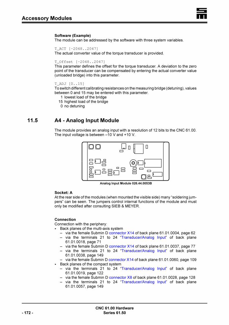
�Accessory Modules
CNC 61.00 Hardware
- 172 - Series 61.50
Analog Input Module 026.44.0053B
Software (Example)The module can be addressed by the software with three system variables.
T_ACT [-2048..2047]The actual converter value of the torque transducer is provided.
T_Offset [-2048..2047]This parameter defines the offset for the torque transducer. A deviation to the zeropoint of the transducer can be compensated by entering the actual converter value(unloaded bridge) into this parameter.
T_ADJ [0..15]To switch different calibrating resistances on the measuring bridge (detuning), valuesbetween 0 and 15 may be entered with this parameter.
1 lowest load of the bridge15 highest load of the bridge
0 no detuning
11.5 A4 - Analog Input Module
The module provides an analog input with a resolution of 12 bits to the CNC 61.00.The input voltage is between –10 V and +10 V.
Socket: AAt the rear side of the modules (when mounted the visible side) many “soldering jum-pers” can be seen. The jumpers control internal functions of the module and mustonly be modified after consulting SIEB & MEYER.
ConnectionConnection with the periphery:< Back planes of the multi-axis system
– via the female Submin D connector X14 of back plane 61.01.0004, page 62– via the terminals 21 to 24 “Transducer/Analog Input” of back plane
61.01.0018, page 71– via the female Submin D connector X14 of back plane 61.01.0037, page 77– via the terminals 21 to 24 “Transducer/Analog Input” of back plane
61.01.0038, page 149– via the female Submin D connector X14 of back plane 61.01.0060, page 109
< Back planes of the compact system– via the terminals 21 to 24 “Transducer/Analog Input” of back plane
61.01.0019, page 122– via the female Submin D connector X8 of back plane 61.01.0028, page 128– via the terminals 21 to 24 “Transducer/Analog Input” of back plane
61.01.0057, page 149

� Accessory Modules
CNC 61.00 Hardware
Series 61.50 - 173 -
Input resistance: RIn . 22 kS

�Accessory Modules
CNC 61.00 Hardware
- 174 - Series 61.50
Transducer and Second Serial Interface 026.44.0067A
Software (Example)The system variable T_ACT provides the actual converter value:Input voltage !10 V = converter value -2048Input voltage 0 V = converter value 0Input voltage 10 V = converter value 2047
The values are achieved, when the negative analog input is connected to groundand the voltage to be measured is connected between the positive analog input andthe ground.
11.6 A5 - Transducer Interface and Second Serial Interface
This module combines the Transducer Interface (A3) and the module of the SecondSerial Interface (A2).
Socket: ABThe four soldering jumpers at the rear side of the modules (when mounted the visi-ble side) serve for the adaptation of the used transducers.J2 closed soldering jumper × 1 mV/V × gain 1,000J2 and J3 closed soldering jumpers × 2 mV/V × gain 500J2 to J4 closed soldering jumpers × 3 mV/V × gain 250J2 to J5 closed soldering jumpers × 4 mV/V × gain 125The jumpers are usually set by SIEB & MEYER according to the user’s requirement,so that later modifications are not necessary.
Connections
The second serial interface is connected to the periphery via the 9-pole femaleSubmin D connector< Back planes for the multi-axis system
– X4 of back plane 61.01.0004, page 62– X4 of back plane 61.01.0018, page 68– X4 of back plane 61.01.0037, page 77– X4 of back plane 61.01.0038, page 83– X4 of back plane 61.01.0060, page 109
< Back planes for the compact system – X4 of back plane 61.01.0019, page 118
– X4 of back plane 61.01.0028, page 128– X4 of back plane 61.01.0057, page 149
The transducer interface is connected to the periphery:

� Accessory Modules
CNC 61.00 Hardware
Series 61.50 - 175 -
< Back planes of the multi-axis system– via the female Submin D connector X14 of back plane 61.01.0004, page 62– via the terminals 21 to 24 “Transducer/Analog Input” of back plane
61.01.0018, page 71– via the female Submin D connector X14 of back plane 61.01.0037, page 77– via the terminals 21 to 24 “Transducer/Analog Input” of back plane
61.01.0038, page 86– via the female Submin D connector X14 of back plane 61.01.0060, page 109
< Back planes of the compact system– via the terminals 21 to 24 “Transducer/Analog Input” of back plane
61.01.0019, page 122– via the female Submin D connector X8 of back plane 61.01.0028, page 128– via the terminals 21 to 24 “Transducer/Analog Input” of back plane
61.01.0057, page 149
Software (Example)See under “A3 - Transducer Interface”, page 170.
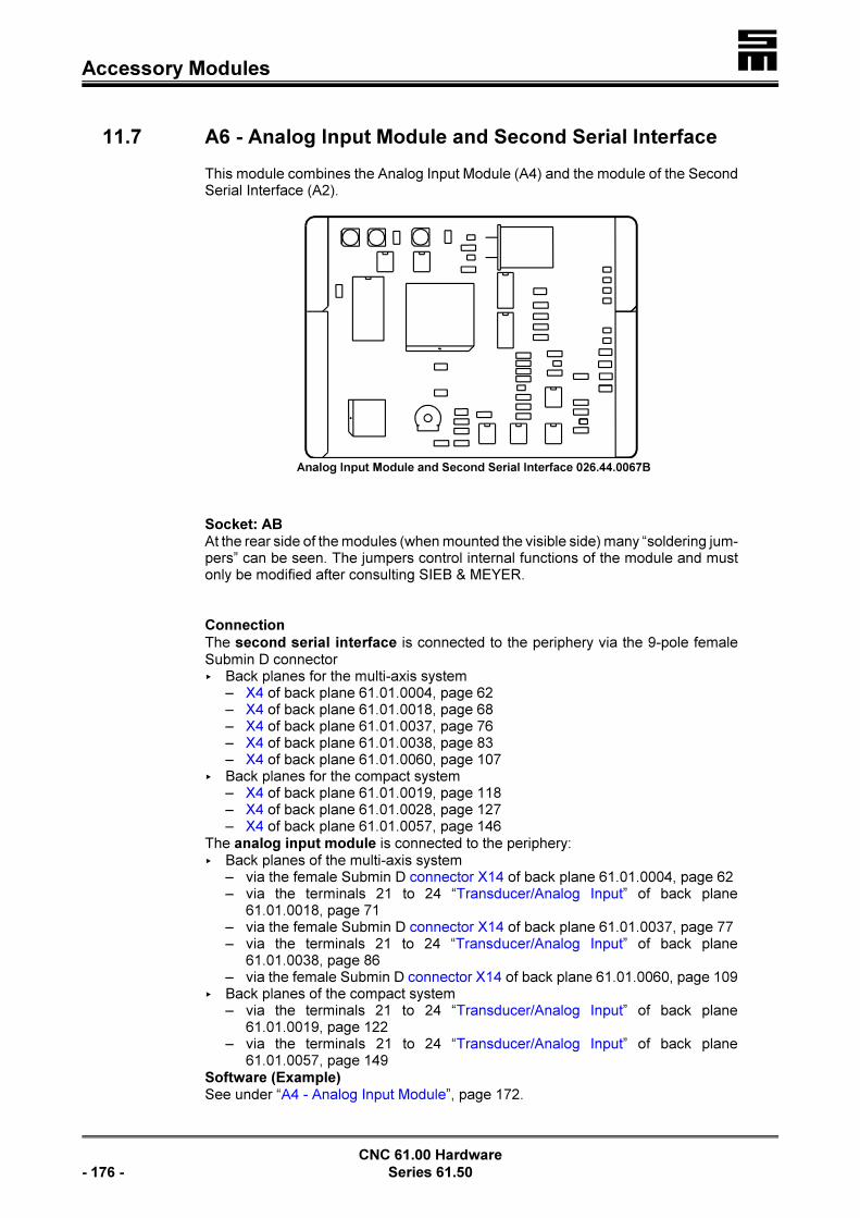
�Accessory Modules
CNC 61.00 Hardware
- 176 - Series 61.50
Analog Input Module and Second Serial Interface 026.44.0067B
11.7 A6 - Analog Input Module and Second Serial Interface
This module combines the Analog Input Module (A4) and the module of the SecondSerial Interface (A2).
Socket: ABAt the rear side of the modules (when mounted the visible side) many “soldering jum-pers” can be seen. The jumpers control internal functions of the module and mustonly be modified after consulting SIEB & MEYER.
Connection
The second serial interface is connected to the periphery via the 9-pole femaleSubmin D connector< Back planes for the multi-axis system
– X4 of back plane 61.01.0004, page 62– X4 of back plane 61.01.0018, page 68– X4 of back plane 61.01.0037, page 76– X4 of back plane 61.01.0038, page 83– X4 of back plane 61.01.0060, page 107
< Back planes for the compact system – X4 of back plane 61.01.0019, page 118
– X4 of back plane 61.01.0028, page 127– X4 of back plane 61.01.0057, page 146
The analog input module is connected to the periphery:< Back planes of the multi-axis system
– via the female Submin D connector X14 of back plane 61.01.0004, page 62– via the terminals 21 to 24 “Transducer/Analog Input” of back plane
61.01.0018, page 71– via the female Submin D connector X14 of back plane 61.01.0037, page 77– via the terminals 21 to 24 “Transducer/Analog Input” of back plane
61.01.0038, page 86– via the female Submin D connector X14 of back plane 61.01.0060, page 109
< Back planes of the compact system– via the terminals 21 to 24 “Transducer/Analog Input” of back plane
61.01.0019, page 122– via the terminals 21 to 24 “Transducer/Analog Input” of back plane
61.01.0057, page 149Software (Example)See under “A4 - Analog Input Module”, page 172.

� Accessory Modules
CNC 61.00 Hardware
Series 61.50 - 177 -
Transducer and Two Serial Interfaces 061.01.0009
11.8 AA - Transducer and Two Serial Interfaces
The interface is an upgrading of the accessory module A5 (transducer and secondserial interface). It has an additional serial interface.
Socket: AThe four soldering jumpers at the rear side of the module (when mounted the visibleside) serve for the adaptation of the used transducers.J2 closed soldering jumper × 1 mV/V × gain 1,000J2 and J3 closed soldering jumpers × 2 mV/V × gain 500J2 to J4 closed soldering jumpers × 3 mV/V × gain 250J2 to J5 closed soldering jumpers × 4 mV/V × gain 125The jumpers are usually set by SIEB & MEYER according to the user’s requirement,so that later modifications are not necessary.
Connection
The serial interfaces are connected to the periphery via the 9-pole female Sub-min D connector X21< of back plane 61.01.0028 for compact systems, page 129< of back plane 61.01.0037 for multi-axis systems, page 78
The transducer interface is connected to the periphery:< via the Submin D connector X8 of back plane 61.01.0028 for compact systems,
page 128< via the Submin D connector X14 of back plane 61.01.0037 for multi-axis systems,
page 109
Software (Example)See under “A3 - Transducer-Interface”, page 170.

�Accessory Modules
CNC 61.00 Hardware
- 178 - Series 61.50
Profibus Interface 061.01.0012
Transducer and Profibus Interface 061.01.0033
11.9 AB - Profibus Interface
The accessory module enables the connection of the Profibus. The module is galva-nically separated from the bus and can be operated with max. 12 MBaud. The firm-ware operates the software connection. The functions can be used independently ofthe used bus system in application programs. Detailed information can be found inchapter “Firmware Functions” and in the description “Communication Protocol DNC61.00”.
Socket: A
ConnectionThe Profibus interface is connected to the periphery via the connectors< multi-axis system
– X5 and X6 of back plane 61.01.0018, pages 91 and 92– X19 of back plane 61.01.0037, page 77– X5 and X6 of back plane 61.01.0053, pages 91 and 92– X19 of back plane 61.01.0058, page 100, 137
< compact system– X8 of back plane 61.01.0019, page 128– X19 of back plane 61.01.0028, page 129– X19 of back plane 61.01.0051, page 137
11.10 AE - Transducer and Profibus Interface
The interface combines the transducer interface (A3) and the Profibus interface(AB).

� Accessory Modules
CNC 61.00 Hardware
Series 61.50 - 179 -

�Accessory Modules
CNC 61.00 Hardware
- 180 - Series 61.50
Socket: AThe four soldering jumpers at the rear side serve for the adaptation of the usedtransducers.J2 closed soldering jumper × 1 mV/V × gain 1,000J2 and J3 closed soldering jumpers × 2 mV/V × gain 500J2 to J4 closed soldering jumpers × 3 mV/V × gain 250J2 to J5 closed soldering jumpers × 4 mV/V × gain 125
The jumpers are usually set by SIEB & MEYER accor-ding to the user’s requirement, so that later modificationsare not necessary.
Connection
The transducer interface is connected to the periphery:< back planes of the multi-axis system
– via the terminals 21 to 24 “Transducer/Analog Input” of back plane61.01.0018, page 71
– via the female Submin D connector X14 of back plane 61.01.0037, page 62< back planes of the compact system
– via the terminals 21 to 24 “Transducer/Analog input” of back plane61.01.0019, page 122
– via the female Submin D connector X8 of back plane 61.01.0028, page 128The Profibus interface is connected to the periphery via the connectors< of the multi-axis system
– X5 and X6 of back plane 61.01.0018, pages 91 and 92– X19 of back plane 61.01.0037, page 77
< of the compact system– X8 of back plane 61.01.0019, page 120– X19 of back plane 61.01.0028, page 129
Software (Example)See under “A3 - Transducer Interface”, page 170. Detailed information can be foundin chapter “Firmware Functions” and in the description “Communication ProtocolDNC 61.00”.

� Accessory Modules
CNC 61.00 Hardware
Series 61.50 - 181 -
Active Transducer and Profibus Interface 061.01.0033A
11.11 AF - Active Transducer and Profibus Interface
The interface is a combination of the Profibus interface (AB) and an active trans-ducer.
Socket: A
Connection
The Profibus interface is connected to the periphery via the connectors< of the multi-axis system
– X5 and X6 of back plane 61.01.0018, pages 91 and 92– X19 of back plane 61.01.0037, page 77– X5 and X6 of back plane 61.01.0053, pages 91 and 92– X19 of back plane 61.01.0058, page 100
< of the compact system– X8 of back plane 61.01.0019, page 120– X19 of back plane 61.01.0028, page 129– X19 of back plane 61.01.0051, page 137
The active transducer is connected to the periphery:< back planes of the multi-axis system
– via the terminals 21 to 24 “Transducer/Analog Input” of back plane61.01.0018, page 71
– via the female Submin D connector X14 of back plane 61.01.0037, page 62– via the female Submin D connector X15 of back plane 61.01.0053, page 93– via the female Submin D connector X15 of back plane 61.01.0058, page 100
< back planes of the compact system– via the terminals 21 to 24 “Transducer/Analog Input” of back plane
61.01.0019, page 122– via the female Submin D connector X8 of back plane 61.01.0028, page 128– via the female Submin D connector X15 of back plane 61.01.0051, page 137

�Accessory Modules
CNC 61.00 Hardware
- 182 - Series 61.50
Profibus and 2 serial interfaces 061.01.0043 Twin transducer and angle pulse input
061.01.0049
11.12 AG – Passive Twin Transducer2 Serial Interfaces, Profibus Interface and Angle Pulse Input 5 V
The accessory module AG consists of two cards:< 61.01.0043 base card with the functions Profibus and two serial interfaces< 61.01.0049 plug-in module with passive twin transducer and angle pulse input
The functions in detail:< Profibus
Physical interface to the Profibus. The bus is galvanically separated from theCNC 61.00 and can be operated up to 12 MBaud. The link to the software is ma-de in the firmware and is provided for the user in the application program, inde-pendently of the used bus system. Detailed information can be found in the ma-nual “Firmware Functions“ and in the manual “Communication Protocol DNC61.00“.
< Serial InterfacesTwo additional serial interfaces as RS232 are provided for the connection of, forexample, printers, bar code scanners, etc., addressable by the application pro-gram.
< Twin TransducersTwo independent passive transducer inputs (measuring bridges for acceptingtorques/forces). The module provides the supply voltage for the measuring bridge(±5 V, max. 400 mA for both transducers) and comprises a measuring amplifier,adjustable via soldering jumpers for the arriving analog signals and a 12 bit ADconverter for the data transmission.
< Angle Pulse InputThe input enables the connection of an additional rotary encoder on the basis of5 V, permitting, for example, the synchronization with another drive.
Socket: ABThe four soldering jumpers on the rear side of module 61.01.0049 serve for theadaptation of the used transducer.J1 closed soldering jumper × 1 mV/V × gain 1,000J1 and J2 closed soldering jumpers × 2 mV/V × gain 500J1 to J3 closed soldering jumpers × 3 mV/V × gain 250J1 to J4 closed soldering jumpers × 4 mV/V × gain 125Usually, the jumpers are preset by SIEB & MEYER according to the user’s require-ments, so that later modifications can be omitted.

� Accessory Modules
CNC 61.00 Hardware
Series 61.50 - 183 -
Connections
Connection of the twin transducer< back planes of the multi-axis system
– via the female Submin D connector X15 of back plane 61.01.0053, page 93– via the female Submin D connector X15 of back plane 61.01.0058, page 100
< back planes of the compact system– via the female Submin D connector X15 of back plane 61.01.0051, page 100,
147
Connection of the Profibus interface< back planes of the multi-axis system
– via the female Submin D connector X5 and the male Submin D connector X6of back plane 61.01.0053, pages 91 and 92
– via the female Submin D connector X19 of back plane 61.01.0058, page 100< back planes of the compact system
– via the female Submin D connector X19 of back plane 61.01.0051, page 137
Connection of the two serial interfaces< back planes of the multi-axis system
– via the female Submin D connector X21 of back plane 61.01.0058, page 101< back planes of the compact system
– via the female Submin D connector X21 of back plane 61.01.0051, page 101,137
Connection of the angle pulse input< back planes of the multi-axis system
– via the female Submin D connector X4 of back plane 61.01.0053, page 91– via the female Submin D connector X4 of back plane 61.01.0058, page 99
< back planes of the compact system– via the female Submin D connector X4 of back plane 61.01.0051, page 136
LThe two serial interfaces are not provided when using the backplane 61.01.0053.If only one transducer input is required, also other back planescan be used. See accessory modules AE and AF, pages 178 and181

�Accessory Modules
CNC 61.00 Hardware
- 184 - Series 61.50
Profibus and 2 serial interfaces 061.01.0043 Twin transducer and angle pulse input
061.01.0044
11.13 AH - Active Twin Transducer2 Serial Interfaces, Profibus Interface and Angle Pulse Input 5 V
The accessory module AH consists of two cards:< 61.01.0043 base card with the functions Profibus and two serial interfaces< 61.01.0044 plug-in module with active twin transducer and angle pulse input
The functions in detail:
< ProfibusPhysical interface to the Profibus. The bus is galvanically separated from theCNC 61.00 and can be operated up to 12 MBaud. The link to the software is ma-de in the firmware and is provided for the user in the application program, inde-pendently of the used bus system. Detailed information can be found in the ma-nual “Firmware Functions“ and in the manual “Communication Protocol DNC61.00“.
< Serial InterfacesTwo additional serial interfaces as RS232 are provided for the connection of, forexample, printers, bar code scanners, etc., addressable by the application pro-gram.
< Twin TransducersTwo independent active transducer inputs (measuring bridges for accepting tor-ques/forces). The module provides the supply voltage for the measuring bridge(±12 V, max. 200 mA for both transducers) and converts the arriving analog sig-nals (±5 V) with a 12 bit AD converter.
< Angle Pulse InputThe input enables the connection of an additional rotary encoder on the basis of5 V, permitting, for example, the synchronization with another drive.
Socket: ABThe soldering jumper on the rear side of the module 61.01.0044 has no relevantfunction for the user and must not be altered.
Connections
Connection of the twin transducer< back planes of the multi-axis system
– via the female Submin D connector X15 of back plane 61.01.0053, page 93– via the female Submin D connector X15 of back plane 61.01.0058, page 100
< back planes of the compact system– via the female Submin D connector X15 of back plane 61.01.0051, page 100,
147

� Accessory Modules
CNC 61.00 Hardware
Series 61.50 - 185 -
�Accessory Modules
CNC 61.00 Hardware
- 186 - Series 61.50
Connection of the Profibus interface< back planes of the multi-axis system
– via the female Submin D connector X5 and the male Submin D connector X6of back plane 61.01.0053, pages 91 and 92
– via the female Submin D connector X19 of back plane 61.01.0058, page 100,137
< back planes of the compact system– via the female Submin D connector X19 of back plane 61.01.0051, page 100,
137
Connection of the two serial interfaces< back planes of the multi-axis system
– via the female Submin D connector X21 of back plane 61.01.0058, page 101< back planes of the compact system
– via the female Submin D connector X21 of back plane 61.01.0051, page 101,137
Connection of the angle pulse input< back planes of the multi-axis system
– via the female Submin D connector X4 of back plane 61.01.0053, page 91– via the female Submin D connector X4 of back plane 61.01.0058, page 99
< back planes of the compact system– via the female Submin D connector X4 of back plane 61.01.0051, page 136
LThe two serial interfaces are not provided when using the backplane 61.01.0053.If only one transduce input is required, also other back planescan be used. See accessory modules AE and AF, pages 178 and181

� Accessory Modules
CNC 61.00 Hardware
Series 61.50 - 187 -
Universal Angle Pulse Module 061.01.0020
11.14 B - Universal Angle Pulse Module
This module is an upgrading of all previously available accessory modules of thecode B and replaces them. In addition, it can process measuring systems with dou-bled input frequency (previously 150 kHz, now 300 kHz).
All accessory modules providing one or two angle pulses show the following basicbehavior:
< Two square-wave signals dephased to each other (track A and track B) are eva-luated to detect the rotational direction of the encoder.
< The input signals of both tracks are galvanically isolated from the evaluation sys-tem via optocouplers. They have to be wired as differential voltage input.
< With each edge change (see figure below) the evaluation electronics generatesa count pulse towards the micro controller (CNC61 controller).
< The maximum count frequency (fmax
) of the micro controller is 1 MHz. This meansthat the minimum spacing between two edges of track A and B is 1/f
max = 1 :s (if
this value falls below 1 :s, pulse losses will occur!)
< This maximum frequency applies for all modules of the series 61.01.0020xx. Forall other module series (e. g. 26.44.0059 etc.) the maximum frequency is 500kHz, and thus the minimum edge spacing is 2 :s.
< For the evaluation of a zero pulse an additional differential voltage input can beused.
< When wiring the angle pulse encoder it is recommended to use a twisted-paircable (1. pair: track A, 2. pair: track B and 3. pair: zero pulse).

�Accessory Modules
CNC 61.00 Hardware
- 188 - Series 61.50
The universal module in detail:
Variant Function Replaced Card New Card Page
BA angle pulse input (24 V) and anglepulse output (5 V)
026.44.0074C 061.01.0020BA
192
B1 angle pulse input 5 V 026.44.0059A 061.01.0020B1
189
B2 angle pulse input (24 V) 026.44.0059B 061.01.0020B2
189
B3 angle pulse output (5 V) 026.44.0060 061.01.0020B3
190
B4 angle pulse input (5 V) and angle pul-se output (5 V)
026.44.0074 061.01.0020B4
190
B5 angle pulse input ( 5V) and angle pul-se input ( 5V)
026.44.0080 061.01.0020B5
190
B7 counter input (5 V) and angle pulseoutput (5 V)
026.44.0074A 061.01.0020B7
191
B8 counter input (24 V) and angle pulseoutput (5 V)
026.44.0074B 061.01.0020B8
191
B9 angle pulse input (24 V) and anglepulse input (5 V)
026.44.0080A 061.01.0020B9
192
Socket: B
ConnectionThe connection facilities of the universal angle pulse module can be found in thedescriptions of the separate accessory modules of the codes B.
Software (Example)Examples can be found in the descriptions of the separate accessory modules of thecode B.

� Accessory Modules
CNC 61.00 Hardware
Series 61.50 - 189 -
11.15 B1/B2 - Incremental Encoder Interface
The module permits to connect an incremental encoder (second measuring system)to the CNC 61.00. Incremental encoders with 5 V/24 V output level can be used. Anexternal encoder can be supplied via the 9-pole Submin D female connector X4 ofthe back planes, but only 24 V incremental encoders.
Socket: B
Difference Between the ModulesThe “soldering jumpers” at the rear side of the module (visible when mounted) servefor the distinction of the incremental encoder used.
All soldering jumpers closed (soldering point): 5 V incremental encoder module (code B1)All soldering jumpers open: 24 V incremental encoder module (code B2)
ConnectionThe module is connected to the periphery via the 9-pole Submin D connector X4 ofall back planes (example of pin assignment, see page 68).The max. count frequency is 150 kHz at the input.
Software (Example)The system variables S_ACT_2, V_ACT_2 and S_LATCH_2 permit to access to thedata of the second measuring system.
S_ACT_2Definition of the position of the measuring system in increments. The variable maybe read and set.
V_ACT_2Actual speed of the measuring system. This value can only be read. Unit:
S_LATCH_2Contains the position of the measuring systems along with the condition of input i4(internal input of the CNC 61.00; Pin 18)
SET 0,S_ACT_2
; set sec. measuring system to Zero
FCT 1, F22 ; edge change at input i4 writes to S_Latch_2; further modes, see function calls
GET S_LATCH_2 ; read the saved value

�Accessory Modules
CNC 61.00 Hardware
- 190 - Series 61.50
11.16 B3 - Angle Pulse Output Module 5 V Level
The module externally provides the angle pulses of the first measuring system. It isuseful, if, for example, two axes shall be synchronized (electronic gear). Axis 1 asmaster then is equipped with the Angle Pulse Output Module, the axis 2 as slave isequipped with the Incremental Encoder Interface of code B1.
Socket: B
ConnectionThe module is connected to the periphery via the 9-pole female Submin D connectorX4 of all back planes (Example of the pin assignment, see page 68).
Driver capacity max. 3 × incremental encoder interface B1/B2 (page 189).
11.17 B4 - Angle Pulse Input and Output Module
The module combines the module B1/B2 (Incremental Encoder Interface) with mo-dule B3 (Angle Pulse Output Module), permitting the operator to use the secondmeasuring system (rotary encoder/CNC 61.00) along with the output of the anglepulses of the first measuring system of the respective axis simultaneously.
Socket: B
ConnectionThe module is connected to the periphery via the 9-pole female Submin D connec-tors X4 and X7 of all back planes, except for the back plane 61.01.0028. Example forthe pin assignment, see pages 60 and 61.
Count frequency at the input: max. 150 kHz
Software (Example)See under “B1/B2 - Incremental Encoder Interface”, page 189.
11.18 B5 - Angle Pulse Input Module, 2-Fold, 5 V Level
The module enables the connection of two incremental encoders (second and thirdmeasuring system) to the CNC 61.00. Encoders with 5 V output level can be connec-ted.
Socket: B
ConnectionsThe module is connected to the periphery via the 9-pole female Submin D connec-tors X4 and X7 of all back planes, except for the back plane 61.01.0028. Example forthe pin assignment, see pages 60 and 61
SoftwareSee under “B1/B2 - Incremental Encoder Interface”, page 189.

� Accessory Modules
CNC 61.00 Hardware
Series 61.50 - 191 -
11.19 B7/B8 - Counter Input and Angle Pulse Output
The module provides a fast counter input and an angle pulse output. The counterinput permits to measure pulses up to 300 kHz. The count direction can be controlledvia the external output UB0+ of the 9-pole female Submin D connector X4 of theback planes.
Socket: BThe “soldering jumpers” at the rear side of the module (visible when mounted) servefor the setting of the counter input:< All soldering jumpers closed (soldering point): 5 V input (variant B7)< All soldering jumpers opened: 24 V input (variant B8)
ConnectionsThe module is connected to the periphery via the 9-pole female Submin D connec-tors X4 and X7 of all back planes, except for the back plane 61.01.0028. Example forthe pin assignment, see pages 60 and 61.
Software (Example)See under “B1/B2 - Incremental Encoder Interface”, page 189.

�Accessory Modules
CNC 61.00 Hardware
- 192 - Series 61.50
11.20 B9 - Angle Pulse Input Module, 2-Fold, 5 V/24 V Levels
The module enables the connection of two incremental encoders (second and thirdmeasuring system) to the CNC 61.00. An encoder with an output level of 5 V and anencoder with an output level of 24 V can be connected.
Socket: B
ConnectionsThe module is connected to the periphery via the 9-pole female Submin D connec-tors X4 and X7 of all back planes, except for the back plane 61.01.0028. Example forthe pin assignment, see pages 60 and 61.
SoftwareSee under “B1/B2 - Incremental Encoder Interface”, page 189.
11.21 BA - Angle Pulse Input 24 V / Angle Pulse Output 5 V
The module combines the accessory modules B2 (angle pulse input with 24 V level)and B3 (angle pulse output with 5 V level).
Socket: B
ConnectionThe module is connected to the periphery via the 9-pole female Submin D connec-tors X4 and X7 of all back planes, except for the back plane 61.01.0028. Example forthe pin assignment, see pages 60 and 61.
Counter frequency at the input: max. 150 kHz
Software (Example)See under “B1/B2 - Incremental Encoder Interface”, page 189.

� Accessory Modules
CNC 61.00 Hardware
Series 61.50 - 193 -
I/O Expansion Interface 026.44.0054
11.22 C1 - I/O Expansion Interface
The module expands the I/O range by farther 128 inputs and outputs. However, theI/O Expansion Interface only connects the CNC to the following Basic Module44.20.012 (page 203) or to the I/O system 50.06, to which input modules 44.20.014and output modules 44.20.013 can be connected in any order. The latter moduleseach provide 16 inputs or outputs.
Socket: C
ConnectionThe module is connected to the periphery via the 9-pole female Submin D connectorX3 of all back planes. Example for the pin assignment, page 59.
Software (Example)
SET 1,O8
; set output 8 to 1 (set; 24 V at the output); 8 is the first output in the external IO area,; since the outputs 0 to 7 are already provided by; the CNC 61.00
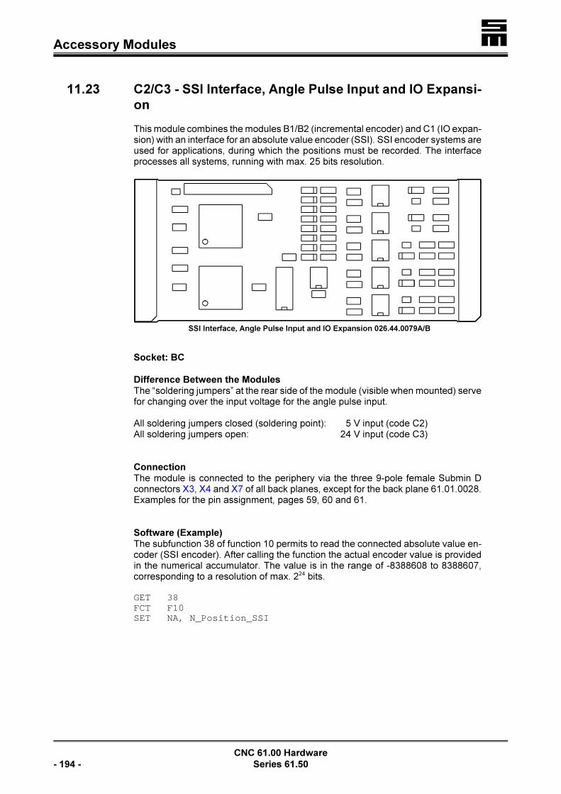
�Accessory Modules
CNC 61.00 Hardware
- 194 - Series 61.50
SSI Interface, Angle Pulse Input and IO Expansion 026.44.0079A/B
11.23 C2/C3 - SSI Interface, Angle Pulse Input and IO Expansi-
on
This module combines the modules B1/B2 (incremental encoder) and C1 (IO expan-sion) with an interface for an absolute value encoder (SSI). SSI encoder systems areused for applications, during which the positions must be recorded. The interfaceprocesses all systems, running with max. 25 bits resolution.
Socket: BC
Difference Between the ModulesThe “soldering jumpers” at the rear side of the module (visible when mounted) servefor changing over the input voltage for the angle pulse input.
All soldering jumpers closed (soldering point): 5 V input (code C2)All soldering jumpers open: 24 V input (code C3)
ConnectionThe module is connected to the periphery via the three 9-pole female Submin Dconnectors X3, X4 and X7 of all back planes, except for the back plane 61.01.0028.Examples for the pin assignment, pages 59, 60 and 61.
Software (Example)The subfunction 38 of function 10 permits to read the connected absolute value en-coder (SSI encoder). After calling the function the actual encoder value is providedin the numerical accumulator. The value is in the range of -8388608 to 8388607,corresponding to a resolution of max. 224 bits.
GET 38FCT F10SET NA, N_Position_SSI

� Accessory Modules
CNC 61.00 Hardware
Series 61.50 - 195 -
SSI Interface, I/O Expansion and Angle Pulse Output 5 V, 061.01.0035
CAN Bus Interface 026.44.0055
11.24 C4 - SSI Interface, I/O Expansion and Angle Pulse Output
5 V
The module is a variant of the accessory module C2, but with the distinction that anangle pulse output with 5 V level is provided instead of the angle pulse input.
Socket: BC
ConnectionThe module is connected to the periphery via the three 9-pole female Submin Dconnectors X3, X4 and X7 of all back planes, except for the back plane 61.01.0028.Examples for the pin assignment, pages 59, 60 and 61.
Software (Example)See under “C2/C3 - SSI Interface, Angle Pulse Input and IO Expansion”, page 194.
11.25 D1 - CAN Bus Interface
LThe CAN Bus Interface cannot be retrofit. That means: It must beordered along with the CNC 61.00.
The module provides the physical connection to the CAN Bus.
Socket: DAt the rear side of the module (when mounted the visible side) two “soldering jum-pers” can be seen. The jumpers whether the module is supplied from the CAN Bus(external supply) or from the CNC 61.00 (internal supply).
Internal supply: Both soldering jumpers are closed. The CNC 61.00 supplies theCAN Bus module. No connection to the external CAN Bus supply.
External supply: Both soldering jumpers are open. The voltage supply for the CANBus module must be made externally.
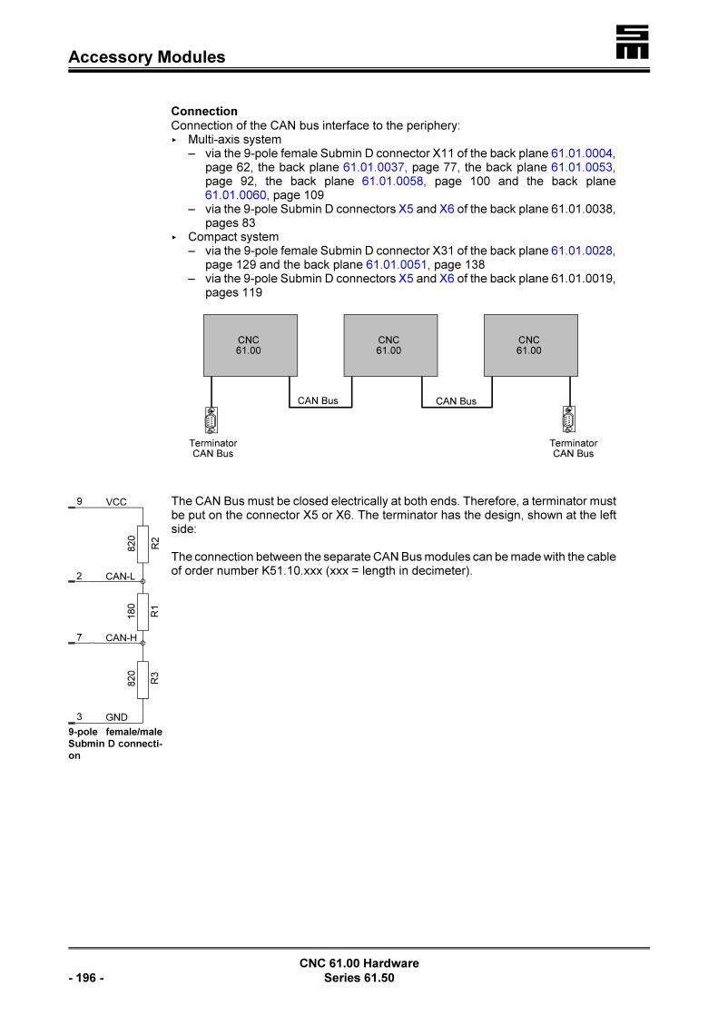
�Accessory Modules
CNC 61.00 Hardware
- 196 - Series 61.50
9-pole female/male
Submin D connecti-
on
ConnectionConnection of the CAN bus interface to the periphery:< Multi-axis system
– via the 9-pole female Submin D connector X11 of the back plane 61.01.0004,page 62, the back plane 61.01.0037, page 77, the back plane 61.01.0053,page 92, the back plane 61.01.0058, page 100 and the back plane61.01.0060, page 109
– via the 9-pole Submin D connectors X5 and X6 of the back plane 61.01.0038,pages 83
< Compact system– via the 9-pole female Submin D connector X31 of the back plane 61.01.0028,
page 129 and the back plane 61.01.0051, page 138– via the 9-pole Submin D connectors X5 and X6 of the back plane 61.01.0019,
pages 119
The CAN Bus must be closed electrically at both ends. Therefore, a terminator mustbe put on the connector X5 or X6. The terminator has the design, shown at the leftside:
The connection between the separate CAN Bus modules can be made with the cableof order number K51.10.xxx (xxx = length in decimeter).
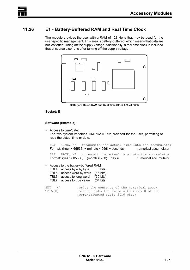
� Accessory Modules
CNC 61.00 Hardware
Series 61.50 - 197 -
Battery-Buffered RAM and Real Time Clock 026.44.0065
11.26 E1 - Battery-Buffered RAM and Real Time Clock
The module provides the user with a RAM of 128 kbyte that may be used for theuser-specific management. This area is battery-buffered, which means that data arenot lost after turning off the supply voltage. Additionally, a real time clock is includedthat of course also runs after turning off the supply voltage.
Socket: E
Software (Example)
< Access to time/date:The two system variables TIME/DATE are provided for the user, permitting toread the actual time or date.
SET TIME, NA ;transmits the actual time into the accumulatorFormat: (hour × 65536) + (minute × 256) + seconds = numerical accumulator
SET DATE, NA ;transmit the actual date into the accumulatorFormat: (year × 65536) + (month × 256) + day = numerical accumulator
< Access to the battery-buffered RAM:TBL4: access byte by byte (8 bits)TBL5: access word by word (16 bits)TBL6: access to long word (32 bits)TBL7: access to true value (64 bits)
SET NA,TBL5[0]
;write the contents of the numerical accu-;mulator into the field with index 0 of the;word-oriented table 5(16 bits)

�Accessory Modules
CNC 61.00 Hardware
- 198 - Series 61.50
Ethernet interface 61.01.0042
11.27 F1 - MODLINK Interface
LThe CAN Bus Interface cannot be retrofit. That means: It must beordered along with the CNC 61.00.
This interface is no pluggable card. Alterations are carried out on the mother board26.44.0041.
The MODLINK bus system serves to build up a network with the CNC 61.00 modu-les. The structure of the bus is a master/slave system, which means that up to 16slaves (CNC 61.00) may be connected to the master (e. g. PC). Physically, theMODLINK is a fast serial bus (4 MBits/s) permitting to provide data of the master atall axes synchronously.
ConnectionsConnection of the MODLINK interface to the periphery:< Multi-axis system
– via the 9-pole Submin D connectors X9 and X10 of the back plane61.01.0004, pages 61 and 62
– via the 9-pole Submin D connectors X9 and X10 of the back plane61.01.0060, pages 108 and 109
– via the 9-pole Submin D connectors X5 and X6 of the back plane 61.01.0038,pages 83 and 84
< Compact system– via the 9-pole Submin D connectors X9 and X10 of the back plane
61.01.0028, pages 128 and 129– via the 9-pole Submin D connectors X5 and X6 of the back plane 61.01.0019,
pages 119
11.28 G1 - Ethernet Interface
LThe Ethernet interface cannot be used along with the MODLINKinterface (F1), since both modules assign identical hardware re-sources.
The accessory module G1 provides the Ethernet functions (10BaseT) for the CNC61.00. The real coupling to the Ethernet then is made with an 8-pole “Western” con-nector on a prepared back plane.

� Accessory Modules
CNC 61.00 Hardware
Series 61.50 - 199 -
Socket: G
�The soldering jumpers on the module are for test purposes
and must not be modified!
ConnectionsConnection of the Ethernet interface with the periphery:< Multi-axis system
– via the 8-pole female Western connector X33 of the back plane 61.01.0053,page 93, the back plane 61.01.0058, page 101 and the back plane61.01.0060, page 110
< Compact system– via the 8-pole female Western connector X33 of the back plane 61.01.0051,
page 138 and the back plane 61.01.0057, page 147
SoftwareThe firmware of the CNC 61.00 provides the TCP/IP protocol, see the manual “Soft-ware Option Ethernet”.

�Accessory Modules
CNC 61.00 Hardware
- 200 - Series 61.50

� External I/O Modules
CNC 61.00 Hardware
Series 61.50 - 201 -
12 External I/O Modules
The CNC 61.00 can be delivered with two input/output systems:< I/O modules 44.20.xx, starting on page 202< I/O modules 50.06.xx, starting on page 213
Connection of the I/O Modules< The I/O system 44.20.xx is connected to the CNC 61.00 with the cable
K61.13.xxx (page 241). It comprises the basic module 44.20.012 and differentinput and output modules, to be mounted in PHOENIX UMK housings on stan-dard DIN EN rails. The connection between the basic module and the CNC 61.00is made between the basic module 44.20.012 and the connector X3 of the backplane. The I/O modules can be varied and cascaded with simple plug-in connec-tions.For applications, just requiring 8 additional inputs or outputs, the I/O Multi-Purpo-se Module 44.20.008 can be used.
< The most significant characteristic of the I/O System 50.06 is its compact con-struction, which in the most cases allows to reduce the size of the switch cabinet.The snap-on mounting and plug-in connection permits the easy and safe connec-tion of the components of the system and of I/O Expansion Modules.The system provides 64 physical connections, which can either be defined as in-or outputs or as bidirectional in-/outputs. Since the system can be adapted todifferent automation purposes via the definition of the number of in- and outputs,it has a high degree of flexibility.
�The accessory module “I/O - Expansion Interface” (C1, page
193) is required for the CNC 61.00. Otherwise, I/O modules
cannot be used.

�I/O Modules 44.20.xx
CNC 61.00 Hardware
- 202 - Series 61.50
Minimum Configuration
12.1 I/O Modules 44.20.xx
12.1.1 Connection Example
Serial I/O Modules:44.20.012 = basic module (transmitter/receiver)44.02.013 = 16 outputs +24 V 100 mA each44.20.014 = 16 inputs +24 V44.20.028 = 8 outputs 1 A each44.20.051 = 8 outputs 1 A (relay) each44.20.053 = 2 × 4 outputs 1 A each
The input/outputs modules can be arranged in any order, but the following order isrecommended: Transmitter/receiver ! inputs ! outputs. Example: Basic module
! inputs ! inputs ! inputs ! outputs ! outputs, etc.
When defining the inputs and outputs in the software, pay attention that the I/O mo-dules, closest to the basic module are assigned with the lowest-order inputs or out-puts.
The M6 earth bolts must be connected at the machine side with the central earthpoint.

� I/O Modules 44.20.xx
CNC 61.00 Hardware
Series 61.50 - 203 -
Basic Module
(Transmitter/Receiver)
voltage connectors
12.1.2 I/O Basic Module 44.20.012
The basic module serves as link between the CNC module and the input/output mo-dules 44.20.013, 44.20.014, 44.20.028, 44.20.051 and 44.20.053. Up to 8 in-put/output modules can be connected to the basic module.
The voltage supply must be connected to the connector K10of the basic module.
Pin Designation
1 0 V
2 24 V
In order to connect the CNC 61.00 to the basic module thecable K61.13.xxx can be used.
DiodesD1 +5 V operating voltageD2 I/O OKD3 load signalD4 clock signalD5 data signal
9-Pole Submin D Connection
Pin Designation Description
1 DO! data out
2 CLK! clock
3 LD! load
4 DI! data in
5 0 V
6 DO+ data out
7 CLK+ clock
8 LD+ load
9 DI+ data in
K9:Connection to the CNC module, connector X3
The figure on the left side shows an earlier module. Todaythe module shown above is used.
Current consumption: approx. 30 mA at 24 V
In order to connect the CNC 61.00 to the basic module thecable K61.02.xxx can be used.

�I/O Modules 44.20.xx
CNC 61.00 Hardware
- 204 - Series 61.50
12.1.3 Output Module 44.20.013
The output module 44.20.013 provides 16 outputs. The CNC module can address upto 128 outputs. The terminal 10 must be connected to 0 V and, terminal 20 to 24 Vas turn-on voltage for the outputs. The total load of the output module is max.350 mA.
One "Enable" input is provided for a group of 8 outputs. Only if the "Enable" input isconnected to 24 V, the outputs can be activated. When the CNC module is turnedon, the outputs are immediately switched to 0 V.
Terminal Designation
1 output 0
2 output 1
3 output 2
4 output 3
5 output 4
6 output 5
7 output 6
8 output 7
9 enable for 0 to 7
10 0 V
11 output 8
12 output 9
13 output 10
14 output 11
15 output 12
16 output 13
17 output 14
18 output 15
19 enable for 8 to 15
20 24 V
The LEDs D1 to D8 and D11 to D18 indicate the status of the outputs 0 to 15 (LEDis on, if the output is active).
�The "Enable" inputs, pins 9 and 19, must be connected to 24
V to use all outputs. The deactivation of an "Enable" input
permits to deactivate output groups (operating program,
switch, etc.).

� I/O Modules 44.20.xx
CNC 61.00 Hardware
Series 61.50 - 205 -
12.1.4 Input Module 44.20.014
The input module 44.20.014 provides 16 inputs. The CNC module can address up to128 inputs. Inputs not wired are internally switched to 0 V.
Terminal Designation
1 input 0
2 input 1
3 input 2
4 input 3
5 input 4
6 input 5
7 input 6
8 input 7
9 input 8
10 input 9
11 input 10
12 input 11
13 input 12
14 input 13
15 input 14
16 input 15
� The interface must be connected to earth via an earth strap in the machine.
The LEDs D1 to D16 indicate the status of the respective input (LED is on, if theinput is active).

�I/O Modules 44.20.xx
CNC 61.00 Hardware
- 206 - Series 61.50
12.1.5 Output Interface 44.20.028
The Output Interface 44.20.028 provides 8 outputs with an increased output currentof 1 A each.
One “Enable” output is provided for the 8 outputs. Only if the “Enable” output is con-nected to 24 V, the outputs can be activated. After turning on the CNC module, alloutputs are immediately switched to 0 V.
Termi-
nal
Designation
1 output 0
2 output 1
3 output 2
4 output 3
5 output 4
6 output 5
7 output 6
8 output 7
9enable for 0 to 7+24 V =̂ all outputs can be activated
10 0 V
11 +24 V voltage supply
12
Recovery diodes must be provided for inductive loads (relays, valves, etc.).
The mircofuse F1 (10 A) protects the +24 V voltage supply. The LED D1 will go on,if the fuse is faulty.
The transistors T1 to T8 switch the outputs.
The LEDs D10 to D17 indicate the status of the outputs (LED is on, if the output isactive).
�To use all outputs, the “Enable” input, Pin 9, must be con-
nected to 24 V. The deactivation of an "Enable" input permits
to deactivate output groups (operating program, switch,
etc.).

� I/O Modules 44.20.xx
CNC 61.00 Hardware
Series 61.50 - 207 -
12.1.6 Output Interface 44.20.051
Up to 8 outputs can be activated with the output module 44.20.051. The all-or-not-hing relays are divided into 2 groups to 4 relays each and can be activated by provi-ding the supply voltages. The outputs are additionally linked with enable signals,permitting to activate outputs in groups, but also to store them. Every output of theCNC can be used as enable signal. Unused enable inputs must be connected to+24 V.
Every module must be supplied with +24 V and 0 V.
Active outputs are switched to +24 V. Every output can be loaded with max. 1 A.
Termi-
nal
Designation
1supply voltage of the relayoutputs 0 to 3
2supply voltage of the relayoutputs 4 to 7
3 0 V
4 enable for all outputs
5
6relay contact output 7
7
8relay contact output 6
9
10relay contact output 5
11
12relay contact output 4
13
14relay contact output 3
15
16relay contact output 2
17
18relay contact output 1
19
20 switch-over contact output 0
21 n/c contact
22 n/o contact
� The interface must be connected to earth with an earth strap in the machine.
The LEDs D10 to D17 indicate the status of the outputs (LED is on, if the output isactive).
The relays K1 to K8 switch the outputs.

�I/O Modules 44.20.xx
CNC 61.00 Hardware
- 208 - Series 61.50
12.1.7 Output Interface 44.20.053
The Output Interface 44.20.053 provides 2 × 4 outputs with an increased output cur-rent of 1 A each.
One “Enable” output is provided for the 8 outputs. Only if the “Enable” output is con-nected to 24 V, the outputs can be activated. After turning on the CNC module, alloutputs are immediately switched to 0 V.
Termi-
nal
Designation
1 output 0
2 output 1
3 output 2
4 output 3
5 output 4
6 output 5
7 output 6
8 output 7
9enable for 0 to 7+24 V =̂ all outputs can be activated
10 0 V
11 +24 V voltage supply for outputs 0 to 3
12 +24 V voltage supply for outputs 4 to 7
The LEDs D1 to D8 indicate the status of the outputs (LED is on, if the output is acti-ve).
The transistors T1 to T8 switch the outputs.
�To use all outputs, the “Enable” input, Pin 9, must be con-
nected to 24 V. The deactivation of an "Enable" input permits
to deactivate output groups (operating program, switch,
etc.).

� I/O Modules 44.20.xx
CNC 61.00 Hardware
Series 61.50 - 209 -
12.1.8 I/O Multi-Purpose Module 44.20.008
If not more than 8 additional inputs and 8 additional outputs are to be connected tothe CNC 61.00, the I/O Multi-Purpose Module 44.20.008 can be used. In this case
it is not necessary to connect the basic module 44.20.012.
The voltage supply must be connected to the connectors, Pins 1 and 2, of the I/OMulti-Purpose Module.
The I/O Multi-Purpose Module 44.20.008 provides 8 outputs. The CNC module thencan address up to 16 outputs in total (including the eight internal outputs). The totalload of the I/O Multi-Purpose Module is 350 mA. All outputs are switched to 0 V im-mediately after turning on the CNC module.
The I/O Multi-Purpose Module 44.20.008 provides 8 inputs. The CNC module thencan address up to 16 inputs in total (including the eight internal inputs). Inputs notwired are internally set to 0 V.
The supply voltage (Pin 1 = +24 V) must be available before turning on the CNC61.00.
Terminal Designation
1 +24 V
2 0 V
3 output 1
4 output 2
5 output 3
6 output 4
7 output 5
8 output 6
9 output 7
10 output 8
11 input 8
12 input 7
13 input 6
14 input 5
15 input 4
16 input 3
17 input 2
18 input 1
Current consumption: approx. 30 mA at 24 VThe cable K61.02.xxx can be used to connect the module with the CNC 61.00.

�I/O Modules 44.20.xx
CNC 61.00 Hardware
- 210 - Series 61.50
Pin Assignment of the 10-Pole Connector to the CNC
DO!: Data Out 1 2 DO+: Data Out
CLK!: Clock 3 4 CLK+: Clock
LD!: Load 5 6 LD+: Load
DI!: Data In 7 8 DI+: Data In
not assigned 9 10 not assigned
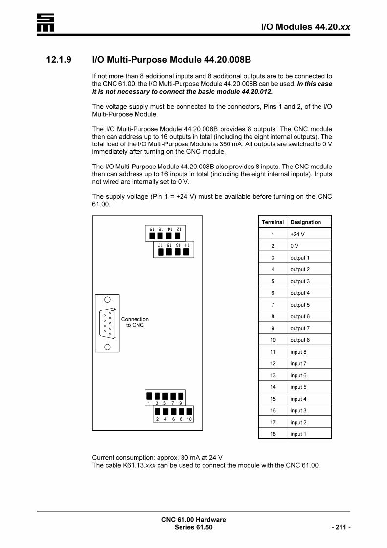
� I/O Modules 44.20.xx
CNC 61.00 Hardware
Series 61.50 - 211 -
12.1.9 I/O Multi-Purpose Module 44.20.008B
If not more than 8 additional inputs and 8 additional outputs are to be connected tothe CNC 61.00, the I/O Multi-Purpose Module 44.20.008B can be used. In this case
it is not necessary to connect the basic module 44.20.012.
The voltage supply must be connected to the connectors, Pins 1 and 2, of the I/OMulti-Purpose Module.
The I/O Multi-Purpose Module 44.20.008B provides 8 outputs. The CNC modulethen can address up to 16 outputs in total (including the eight internal outputs). Thetotal load of the I/O Multi-Purpose Module is 350 mA. All outputs are switched to 0 Vimmediately after turning on the CNC module.
The I/O Multi-Purpose Module 44.20.008B also provides 8 inputs. The CNC modulethen can address up to 16 inputs in total (including the eight internal inputs). Inputsnot wired are internally set to 0 V.
The supply voltage (Pin 1 = +24 V) must be available before turning on the CNC61.00.
Terminal Designation
1 +24 V
2 0 V
3 output 1
4 output 2
5 output 3
6 output 4
7 output 5
8 output 6
9 output 7
10 output 8
11 input 8
12 input 7
13 input 6
14 input 5
15 input 4
16 input 3
17 input 2
18 input 1
Current consumption: approx. 30 mA at 24 VThe cable K61.13.xxx can be used to connect the module with the CNC 61.00.

�I/O Modules 44.20.xx
CNC 61.00 Hardware
- 212 - Series 61.50
Pin Assignment of the 9-Pole Submin D Connector to the CNC
DO!: Data Out 16 DO+: Data Out
CLK!: Clock 27 CLK+: Clock
LD!: Load 38 LD+: Load
DI!: Data In 49 DI+: Data In
0 V 5
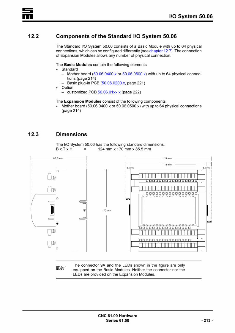
� I/O System 50.06
CNC 61.00 Hardware
Series 61.50 - 213 -
12.2 Components of the Standard I/O System 50.06
The Standard I/O System 50.06 consists of a Basic Module with up to 64 physicalconnections, which can be configured differently (see chapter 12.7). The connectionof Expansion Modules allows any number of physical connection.
The Basic Modules contain the following elements:< Standard
– Mother board (50.06.0400.x or 50.06.0500.x) with up to 64 physical connec-tions (page 214)
– Basic plug-in PCB (50.06.0200.x, page 221) < Option
– customized PCB 50.06.01xx.x (page 222)
The Expansion Modules consist of the following components:< Mother board (50.06.0400.x or 50.06.0500.x) with up to 64 physical connections
(page 214)
12.3 Dimensions
The I/O System 50.06 has the following standard dimensions:B x T x H = 124 mm x 170 mm x 85.5 mm
LThe connector 9A and the LEDs shown in the figure are onlyequipped on the Basic Modules. Neither the connector nor theLEDs are provided on the Expansion Modules.

�I/O System 50.06
CNC 61.00 Hardware
- 214 - Series 61.50
12.4 Mother Board
All Basic and Expansion Modules of the Standard I/O System 50.06 are equippedwith the mother board. The mother board 50.06.0400.x is used in modules with low-side outputs (50.06.30 / 50.06.130) and the mother board 50.06.0500.x is used inBasic and Expansion Modules with high-side outputs (see chapter 12.7 "Modules").

� I/O System 50.06
CNC 61.00 Hardware
Series 61.50 - 215 -
X1 to X4I/O plug-in connectors
Physical Connection Assignment
1 logical input / output 0*
.
.
.
16 logical input / output 15
17 +24 V
18 GND
D1 to D64LEDs indicating the I/O status
LED Color Status Meaning
LED for input green �input active +2
4 V
LED for output yellow �output active+24 V
X11 / X12Connection of Expansion Modules
X13 / X14Connection between the plug-in PCB 50.06.0200.x and the mother board50.06.0400.x or 50.06.0500.x (page 214 et seq.)
X15Connection of customized PCBs 50.06.01xx.x (page 222)

�I/O System 50.06
CNC 61.00 Hardware
- 216 - Series 61.50
The different number of in- and outputs or bidirectional in- / outputs is achieved bythe corresponding mounted components on the PCB 50.06.0500.x (cf. page 214).Thecoded variant designation of PCB 50.06.0500 determines the number of in- and out-puts or bidirectional in- / outputs.
All in all, each module provides 64 physical connections at maximum (see tablebelow, formula). Eight of these physical connections can be used on a customizedPCB (50.06.01xx.x, see page 222) for specialized developments (e.g. AD/DA con-verters, counters).
Equipment Variant
of Plug-In PCB
50.06.0500.x
Inputs
(I)
Outputs
(O)
Bidirectional
Inputs/Outputs
(I/O)
Equipment Variant of
Customized PCB 50.06.01xx.x (S)
Va-
riant
Su
m
A 0 0 0 A PCB not provided
B 8 8 8 B50.06.0100.x
2 x 11 bits ±10 V analog output2 x 11 bits ±10 V analog input
C 16 16 16 -1
D 24 24 24 -1
E 32 32 32 -1
F 40 40 40 -1
G 48 48 48 -1
H 56 56 56 -1
I 64 64 64 -1
J reserved
Formula: (I) (O) (I/O) (S) #64
Examples: 50.06.0500þ
D C C B
DCCB 6424 I 16 O
16 bidirectionalinputs/outputs
8 customized physical connections
1
Further variants of the customized PCB 50.06.01xx.x can be provided by diffe-rent equipment (page 222).
The first letter in the coded variant designation generally determines the number ofinputs mounted on the PCB 50.06.0500.x, the second letter of the number of moun-ted outputs etc.

� I/O System 50.06
CNC 61.00 Hardware
Series 61.50 - 217 -
12.4.1 Wiring of the In- and Outputs on the Mother Board
The type of physical connection is defined by the corresponding components moun-ted on the PCB.
Inputs
The LEDs for the inputs are green. If the LED is flashing, the input is active.
Outputs (Low-Side)
The LEDs for the inputs are yellow. If the LED is flashing, the input is active.
Bidirectional In- and Outputs (Low-Side)
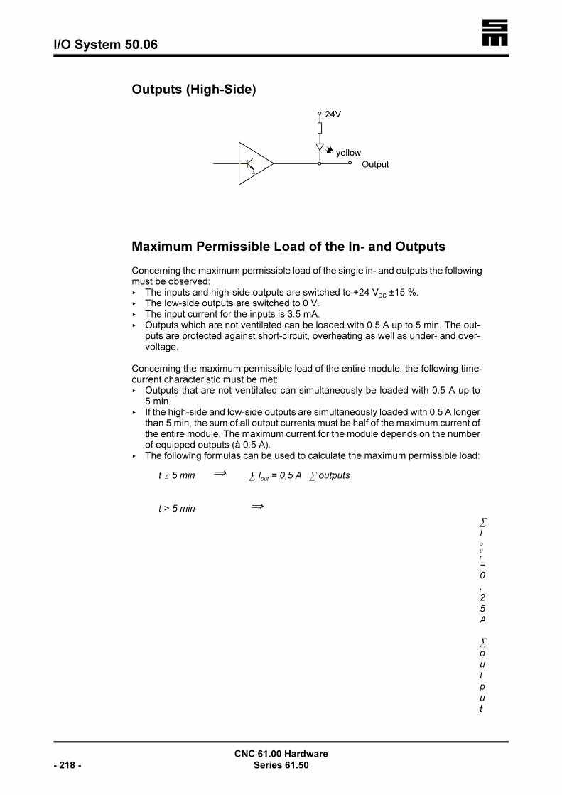
�I/O System 50.06
CNC 61.00 Hardware
- 218 - Series 61.50
Outputs (High-Side)
Maximum Permissible Load of the In- and Outputs
Concerning the maximum permissible load of the single in- and outputs the followingmust be observed:< The inputs and high-side outputs are switched to +24 VDC ±15 %.< The low-side outputs are switched to 0 V.< The input current for the inputs is 3.5 mA.< Outputs which are not ventilated can be loaded with 0.5 A up to 5 min. The out-
puts are protected against short-circuit, overheating as well as under- and over-voltage.
Concerning the maximum permissible load of the entire module, the following time-current characteristic must be met:< Outputs that are not ventilated can simultaneously be loaded with 0.5 A up to
5 min.< If the high-side and low-side outputs are simultaneously loaded with 0.5 A longer
than 5 min, the sum of all output currents must be half of the maximum current ofthe entire module. The maximum current for the module depends on the numberof equipped outputs (à 0.5 A).
< The following formulas can be used to calculate the maximum permissible load:
t # 5 min Y 3 Iout
= 0,5 A 3 outputs
t > 5 min Y
3
Io
u
t
=
0
,
2
5
A
3
o
u
t
p
u
t

� I/O System 50.06
CNC 61.00 Hardware
Series 61.50 - 219 -
s
�If outputs are to be loaded with 0.5 A without time limit, ven-
tilation measures must absolutely be assured.
< In this case, the maximum permissible load is calculated as follows:
t 4 Y 3 Iout
= 0,5 A 3 outputs

�I/O System 50.06
CNC 61.00 Hardware
- 220 - Series 61.50
Interlocking the Outputs
In applications which are critical with regard to safety, it is recommended to interlockapplication-specific outputs by additional relays.
The following figure shows exemplary the interlock of a drilling spindle tong viaspeed n = 0. This single interlock is carried out via switching the ground potential.
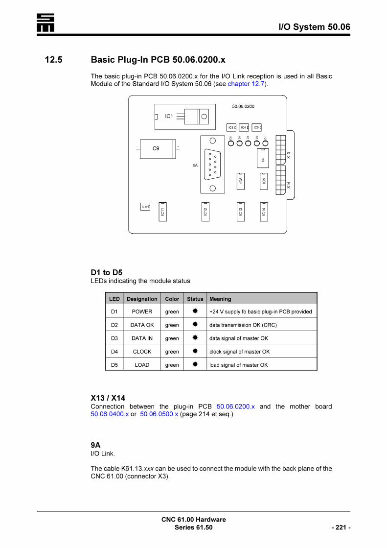
� I/O System 50.06
CNC 61.00 Hardware
Series 61.50 - 221 -
12.5 Basic Plug-In PCB 50.06.0200.x
The basic plug-in PCB 50.06.0200.x for the I/O Link reception is used in all BasicModule of the Standard I/O System 50.06 (see chapter 12.7).
D1 to D5LEDs indicating the module status
LED Designation Color Status Meaning
D1 POWER green � +24 V supply fo basic plug-in PCB provided
D2 DATA OK green � data transmission OK (CRC)
D3 DATA IN green � data signal of master OK
D4 CLOCK green � clock signal of master OK
D5 LOAD green � load signal of master OK
X13 / X14Connection between the plug-in PCB 50.06.0200.x and the mother board50.06.0400.x or 50.06.0500.x (page 214 et seq.)
9AI/O Link.
The cable K61.13.xxx can be used to connect the module with the back plane of theCNC 61.00 (connector X3).
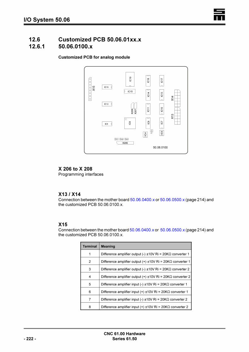
�I/O System 50.06
CNC 61.00 Hardware
- 222 - Series 61.50
12.6 Customized PCB 50.06.01xx.x
12.6.1 50.06.0100.x
Customized PCB for analog module
X 206 to X 208 Programming interfaces
X13 / X14Connection between the mother board 50.06.0400.x or 50.06.0500.x (page 214) andthe customized PCB 50.06.0100.x.
X15Connection between the mother board 50.06.0400.x or 50.06.0500.x (page 214) andthe customized PCB 50.06.0100.x.
Terminal Meaning
1 Difference amplifier output (-) ±10V Ri = 20KS converter 1
2 Difference amplifier output (+) ±10V Ri = 20KS converter 1
3 Difference amplifier output (-) ±10V Ri = 20KS converter 2
4 Difference amplifier output (+) ±10V Ri = 20KS converter 2
5 Difference amplifier input (-) ±10V Ri = 20KS converter 1
6 Difference amplifier input (+) ±10V Ri = 20KS converter 1
7 Difference amplifier input (-) ±10V Ri = 20KS converter 2
8 Difference amplifier input (+) ±10V Ri = 20KS converter 2

� I/O System 50.06
CNC 61.00 Hardware
Series 61.50 - 223 -
Wiring of the In- and Outputs on the PCB 50.06.0100.x
InputsInput lines ±10V, ±11 bits resolution
OutputsOutput lines ±10V, ±11 bits resolution
12.7 IO Modules
The Basic Modules of the Standard I/O System 50.06 are equipped with the plug-inPCB for the I/O Link reception 50.06.0200.x and the mother board 50.06.0400.x or50.06.0500.x. Furthermore, the Basic Modules 50.06.2xx and 50.06.5xx are providedwith the customized PCB 50.06.01xx.x (see chapter 12.4 and sections 12.8.1).
The number of in- and outputs can be increased by connecting the Expansion Modu-les. The Expansion Modules are not equipped with an additional mother board for theI/O Link reception (50.06.020x.x), but only with the mother board (50.06.0400.x or50.06.0500.x). The number of in-and outputs is defined via the equipment variant ofthe plug-in PCB 50.06.0500.x.

�I/O System 50.06
CNC 61.00 Hardware
- 224 - Series 61.50
12.8 Module Designations
The type and equipment variant of the module as well as the number of provided in-and outputs can be derived from the module designation.
The following code designations are used for the different modules:
Module Designation Function Components
50.06.1x
Basic module I/O50.06.0200.x50.06.0500.x with up to 64 physical connections
50.06.2x
50.06.3x
50.06.1xx Expansion module I/O 50.06.0500.x with up to 64 physical connections
50.06.2xxBasic module I/Owith customized PCB
50.06.0200.x50.06.0500.x with up to 56 physical connections50.06.01xx.x with up to 8 physical connections
50.06.3xxBasic module B(bidirectional)
50.06.0200.x50.06.0500.x with up to 64 bidirectional physical connections
50.06.4xxExpansion module B(bidirectional)
50.06.0500.x with up to 64 bidirectional physical connections
50.06.5xxBasic module B(bidirectional) with customized PCB
50.06.0200.x50.06.0500.x with up to 56 bidirectional physical connections50.06.01xx.x with up to 8 physical connections
50.06.10xx reserved
50.06.12xx reserved
50.06.20xx reserved
12.8.1 Module 50.06.1x
Basic module I/O with up to 64 physical connections
In the Basic Modules of group 50.06.1x generally all of the 64 physical connectionson the PCB 50.06.0500.x are mounted as in- or outputs.
Module Designation Inputs Outputs
50.06.10 64 0
50.06.11 56 8
50.06.12 (page 229) 48 16
50.06.13 40 24
50.06.14 (page 229) 32 32
50.06.15 24 40
50.06.16 16 48
50.06.17 8 56
50.06.18 0 64
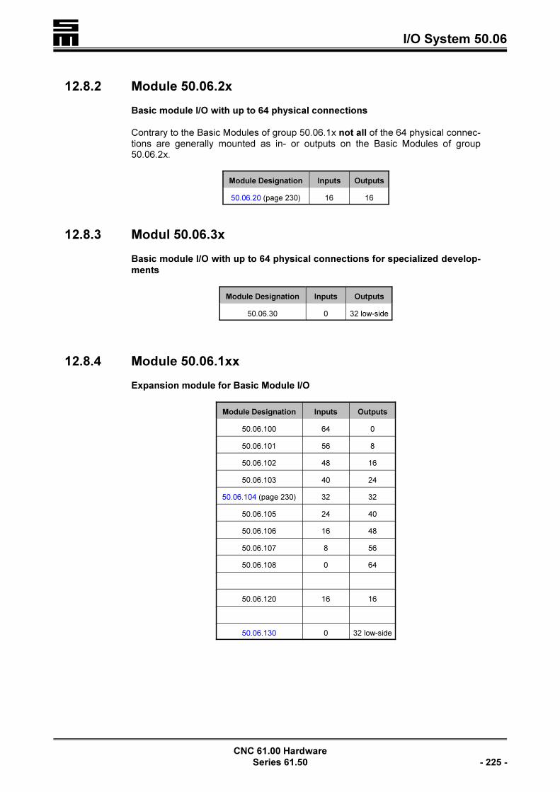
� I/O System 50.06
CNC 61.00 Hardware
Series 61.50 - 225 -
12.8.2 Module 50.06.2x
Basic module I/O with up to 64 physical connections
Contrary to the Basic Modules of group 50.06.1x not all of the 64 physical connec-tions are generally mounted as in- or outputs on the Basic Modules of group50.06.2x.
Module Designation Inputs Outputs
50.06.20 (page 230) 16 16
12.8.3 Modul 50.06.3x
Basic module I/O with up to 64 physical connections for specialized develop-
ments
Module Designation Inputs Outputs
50.06.30 0 32 low-side
12.8.4 Module 50.06.1xx
Expansion module for Basic Module I/O
Module Designation Inputs Outputs
50.06.100 64 0
50.06.101 56 8
50.06.102 48 16
50.06.103 40 24
50.06.104 (page 230) 32 32
50.06.105 24 40
50.06.106 16 48
50.06.107 8 56
50.06.108 0 64
50.06.120 16 16
50.06.130 0 32 low-side
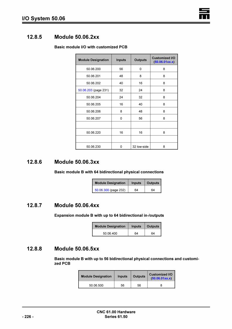
�I/O System 50.06
CNC 61.00 Hardware
- 226 - Series 61.50
12.8.5 Module 50.06.2xx
Basic module I/O with customized PCB
Module Designation Inputs OutputsCustomized I/O
(50.06.01xx.x)
50.06.200 56 0 8
50.06.201 48 8 8
50.06.202 40 16 8
50.06.203 (page 231) 32 24 8
50.06.204 24 32 8
50.06.205 16 40 8
50.06.206 8 48 8
50.06.207 0 56 8
50.06.220 16 16 8
50.06.230 0 32 low-side 8
12.8.6 Module 50.06.3xx
Basic module B with 64 bidirectional physical connections
Module Designation Inputs Outputs
50.06.300 (page 232) 64 64
12.8.7 Module 50.06.4xx
Expansion module B with up to 64 bidirectional in-/outputs
Module Designation Inputs Outputs
50.06.400 64 64
12.8.8 Module 50.06.5xx
Basic module B with up to 56 bidirectional physical connections and customi-
zed PCB
Module Designation Inputs OutputsCustomized I/O
(50.06.01xx.x)
50.06.500 56 56 8

� I/O System 50.06
CNC 61.00 Hardware
Series 61.50 - 227 -
12.9 Assignment of the Physical Connections
When assigning the in- and outputs, bidirectional in- / outputs and customized in- /outputs to the physical connections, the following must be observed:
< Always observe the module's position shown in the figure below.
< The assignment of the in- / outputs, bidirectional in- / outputs and customized in- /outputs is carried out in groups of eight physical connections, beginning with thephysical connection 1 at the terminal bar X1. During the assignment, the followingorder must be observed: customized I/O - inputs - outputs - bidirectional I/O.The following order must be observed:customized I/O - inputs - outputs - bidirectional I/O.
< Consider that the counter for each kind of in- and output begins with 0 in the soft-ware, i.e. for example that the input 0 is assigned to the physical connection 1.
< The appropriate assignment of the physical connections is printed on the modu-les. For this purpose, the following abbreviations are used:
IN inputs
OUT outputs
C-... customized PCB-variant
BI bidirectional in-/outputs
LThe connector 9A and the LEDs shown in the figure are onlyequipped on the Basic Modules. Neither the connector nor theLEDs are provided on the Expansion Modules.

�I/O System 50.06
CNC 61.00 Hardware
- 228 - Series 61.50
The physical connections are divided into groups of eight and can be assigned asfollows according to the order mentioned above:
Group Physical Connection Equipment Possibility
A 1 to 8ororor
customized PCBinputsoutputsbidirectional I/O
B 9 to 16 oror
inputsoutputsbidirectional I/O
C 17 to 24 oror
inputsoutputsbidirectional I/O
D 25 to 32 oror
inputsoutputsbidirectional I/O
E 33 to 40 oror
inputsoutputsbidirectional I/O
F 41 to 48 oror
inputsoutputsbidirectional I/O
G 49 to 56 oror
inputsoutputsbidirectional I/O
H 57 to 64 oror
inputsoutputsbidirectional I/O
12.9.1 Examples
The assignment of some modules is shown in the following section. The differentassignment of the physical connections is represented by the following symbols:
< Input E
< Output A
< Customized I/O K
< Bidirectional I/O B
< Firmly defined physical connection F

� I/O System 50.06
CNC 61.00 Hardware
Series 61.50 - 229 -
50.06.12
Basic module I/O with 48 inputs and 16 outputs
50.06.14
Basic module I/O with 32 inputs and 32 outputs
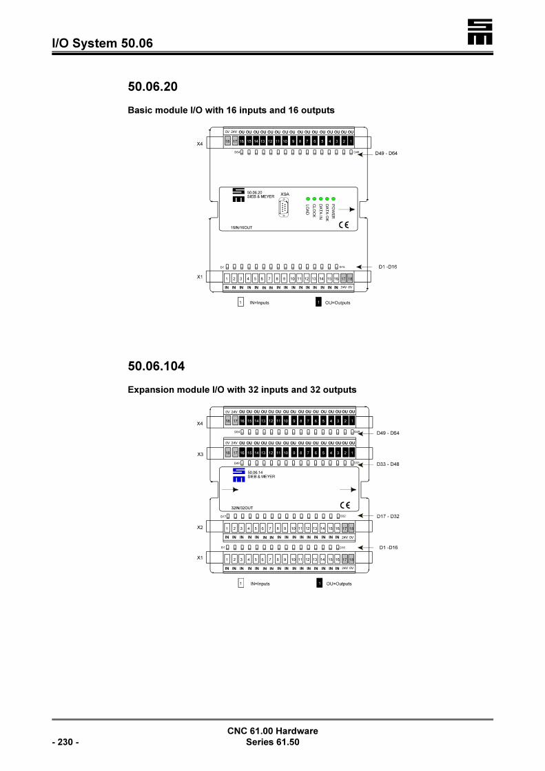
�I/O System 50.06
CNC 61.00 Hardware
- 230 - Series 61.50
50.06.20
Basic module I/O with 16 inputs and 16 outputs
50.06.104
Expansion module I/O with 32 inputs and 32 outputs

� I/O System 50.06
CNC 61.00 Hardware
Series 61.50 - 231 -
50.06.130
Expansion module I/O with 32 low-side outputs
50.06.203
Basic Module I/O with 32 inputs, 24 outputs and customized PCB 50.06.0100.x
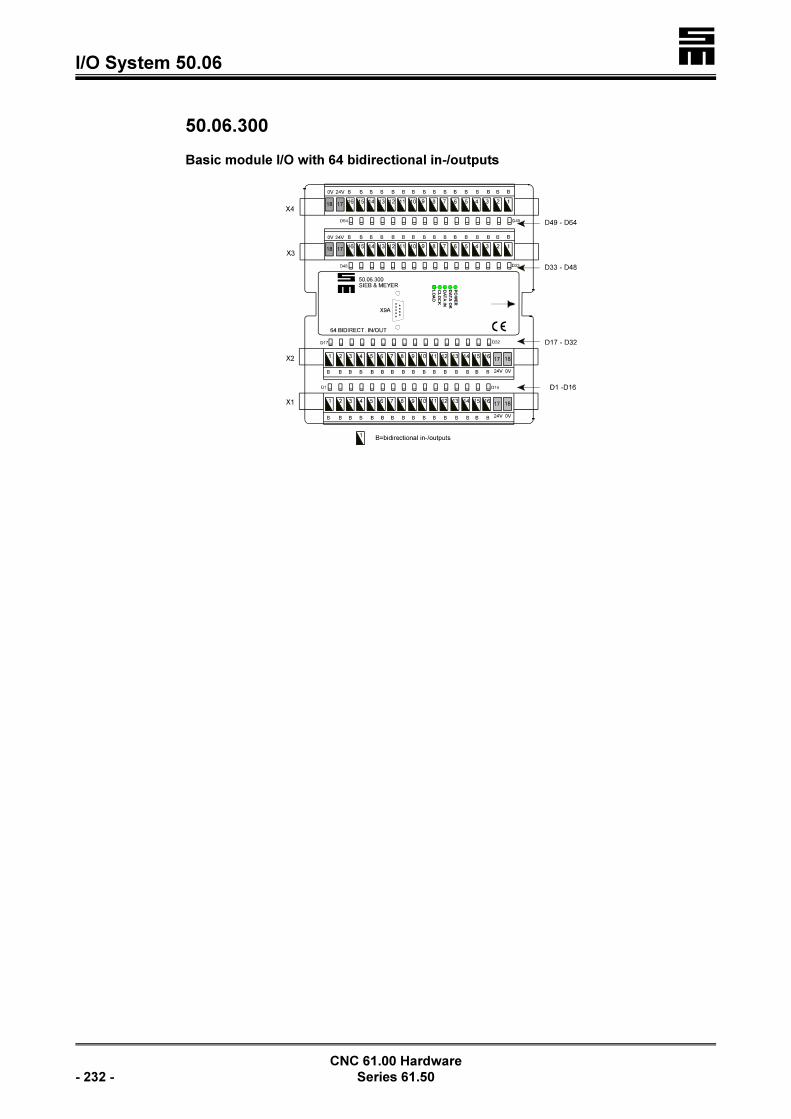
�I/O System 50.06
CNC 61.00 Hardware
- 232 - Series 61.50
50.06.300
Basic module I/O with 64 bidirectional in-/outputs

� The Logic Cards
CNC 61.00 Hardware
Series 61.50 - 233 -
13 The Logic Cards
13.1 Logic Card 61.01.0003 (Resolver Evaluation, Trapezoidal
Commutation)
The logic card has a hardware identification, permitting the CNC 61.00 to identify thehardware during the operation. For this logic card ID = 188 is generated.
The logic card has 16 LEDs (2 × 8), reflecting the status of the 8 internal inputs or 8internal outputs. When a LED is on, a 24 V signal is provided at the respective inputor output.

�The Logic Cards
CNC 61.00 Hardware
- 234 - Series 61.50
13.2 Logic Card 61.01.0022 (Resolver Evaluation, Sinusoidal
Commutation)
The logic card has a hardware identification, permitting the CNC 61.00 to identify thehardware during the operation. For this logic card ID = 174 is generated.
The logic card has 16 LEDs (2 × 8), reflecting the status of the 8 internal inputs or 8internal outputs. When a LED is on, a 24 V signal is provided at the respective inputor output.
J2 Resolution of the current feed forward (plugged as a standard)J3 Resolution of the current feed forward
�Contacting SIEB & MEYER is indispensable before altering
the jumper positions! A different firmware might be installed.

� The Logic Cards
CNC 61.00 Hardware
Series 61.50 - 235 -
13.3 Logic Card 61.01.0023 (Synchronous Linear Motors, Sinu-
soidal Commutation)
The logic card has a hardware identification, permitting the CNC 61.00 to identify thehardware during the operation. For this logic card ID = 236 is generated.
The logic card has 16 LEDs (2 × 8), reflecting the status of the 8 internal inputs or 8internal outputs. When a LED is on, a 24 V signal is provided at the respective inputor output.
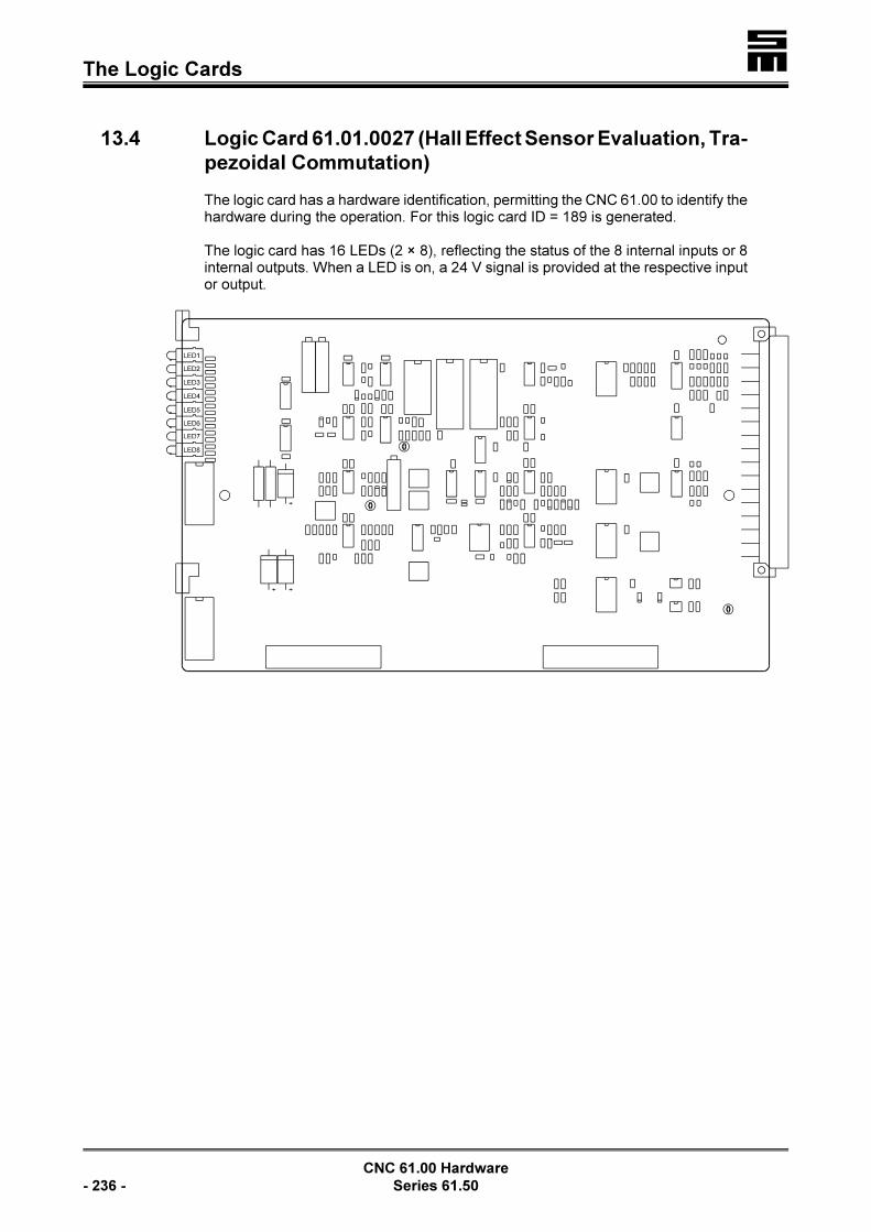
�The Logic Cards
CNC 61.00 Hardware
- 236 - Series 61.50
13.4 Logic Card 61.01.0027 (Hall Effect Sensor Evaluation, Tra-
pezoidal Commutation)
The logic card has a hardware identification, permitting the CNC 61.00 to identify thehardware during the operation. For this logic card ID = 189 is generated.
The logic card has 16 LEDs (2 × 8), reflecting the status of the 8 internal inputs or 8internal outputs. When a LED is on, a 24 V signal is provided at the respective inputor output.
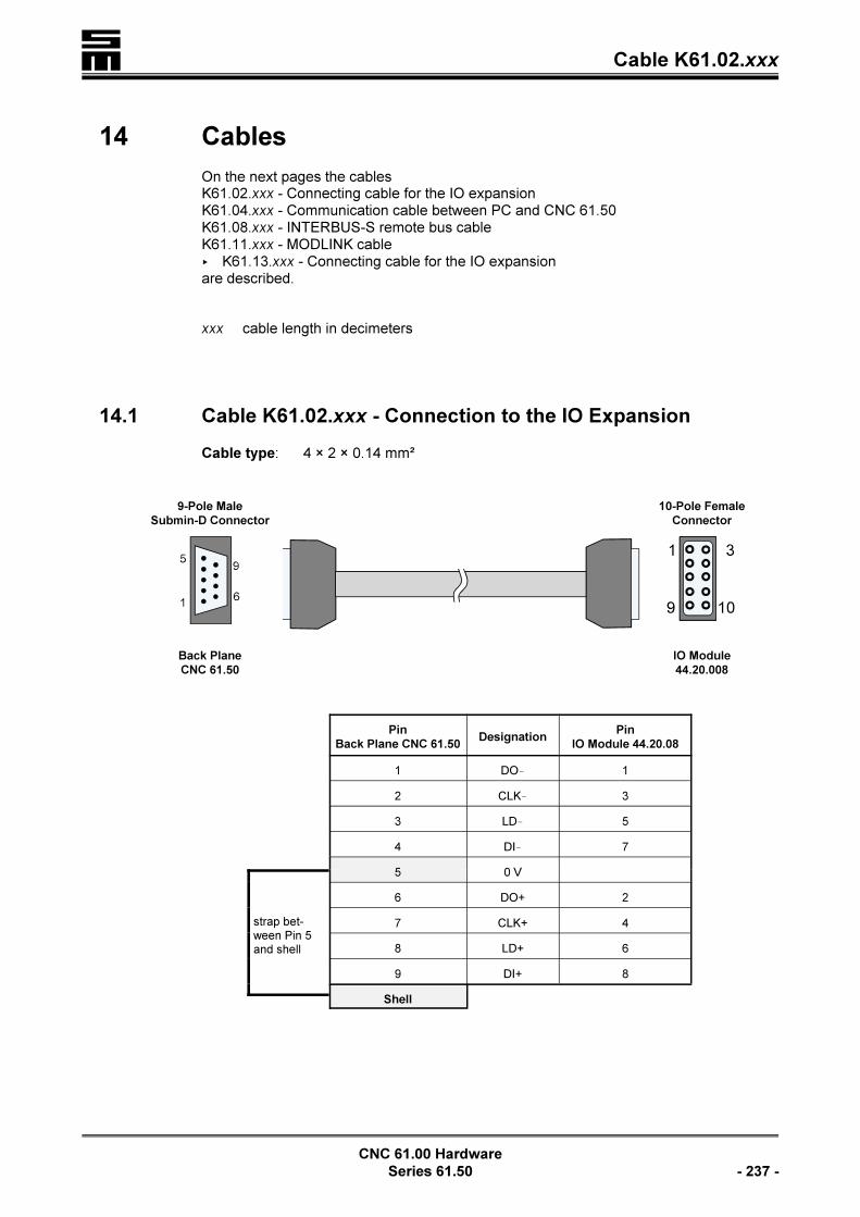
� Cable K61.02.xxx
CNC 61.00 Hardware
Series 61.50 - 237 -
14 Cables
On the next pages the cablesK61.02.xxx - Connecting cable for the IO expansionK61.04.xxx - Communication cable between PC and CNC 61.50K61.08.xxx - INTERBUS-S remote bus cableK61.11.xxx - MODLINK cable< K61.13.xxx - Connecting cable for the IO expansionare described.
xxx cable length in decimeters
14.1 Cable K61.02.xxx - Connection to the IO Expansion
Cable type: 4 × 2 × 0.14 mm²
9-Pole Male
Submin-D Connector
10-Pole Female
Connector
Back Plane
CNC 61.50
IO Module
44.20.008
Pin
Back Plane CNC 61.50Designation
Pin
IO Module 44.20.08
1 DO! 1
2 CLK! 3
3 LD! 5
4 DI! 7
5 0 V
strap bet-ween Pin 5and shell
6 DO+ 2
7 CLK+ 4
8 LD+ 6
9 DI+ 8
Shell

�Cable K61.04.xxx
CNC 61.00 Hardware
- 238 - Series 61.50
14.2 Cable K61.04.xxx - Communication between PC and CNC
61.00
Cable type: 3 × 0.14 mm²
9-Pole Male
Submin-D Connector
9-Pole Female
Submin-D Connector
CNC 61.50 PC
Pin
CNC 61.50Designation
Pin
PC
1 --- 1
2 TxD 2
3 RxD 3
4 --- 4
5 GND 5
6 --- 6
7 --- 7
8 --- 8
9 --- 9
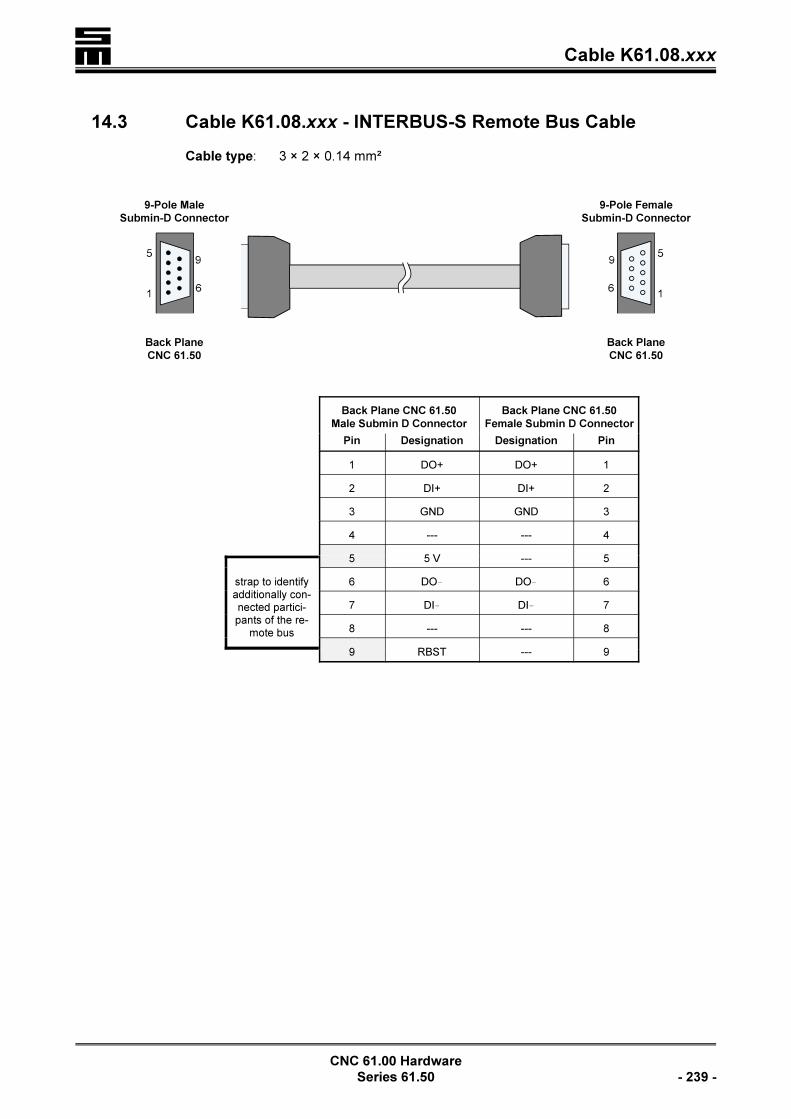
� Cable K61.08.xxx
CNC 61.00 Hardware
Series 61.50 - 239 -
14.3 Cable K61.08.xxx - INTERBUS-S Remote Bus Cable
Cable type: 3 × 2 × 0.14 mm²
9-Pole Male
Submin-D Connector
9-Pole Female
Submin-D Connector
Back Plane
CNC 61.50
Back Plane
CNC 61.50
Back Plane CNC 61.50
Male Submin D Connector
Back Plane CNC 61.50
Female Submin D Connector
Pin Designation Designation Pin
1 DO+ DO+ 1
2 DI+ DI+ 2
3 GND GND 3
4 --- --- 4
5 5 V --- 5
strap to identifyadditionally con-nected partici-pants of the re-
mote bus
6 DO! DO! 6
7 DI! DI! 7
8 --- --- 8
9 RBST --- 9
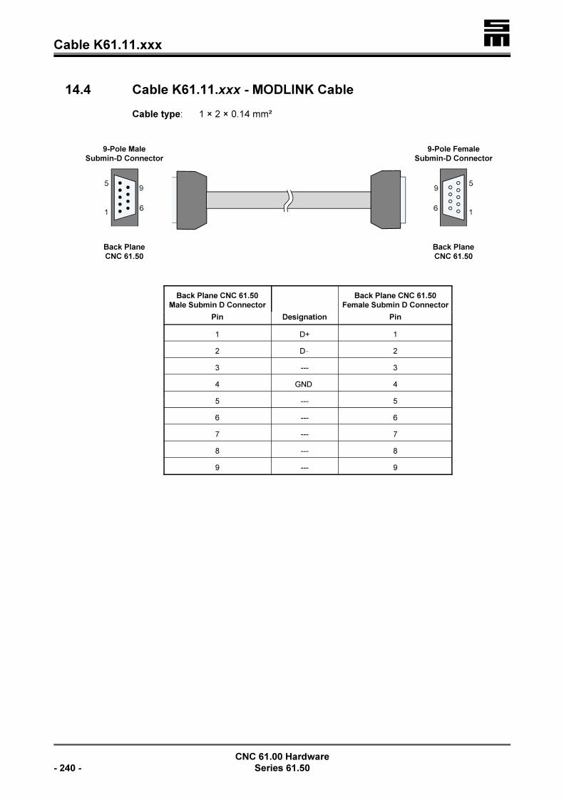
�Cable K61.11.xxx
CNC 61.00 Hardware
- 240 - Series 61.50
14.4 Cable K61.11.xxx - MODLINK Cable
Cable type: 1 × 2 × 0.14 mm²
9-Pole Male
Submin-D Connector
9-Pole Female
Submin-D Connector
Back Plane
CNC 61.50
Back Plane
CNC 61.50
Back Plane CNC 61.50
Male Submin D Connector
Back Plane CNC 61.50
Female Submin D Connector
Pin Designation Pin
1 D+ 1
2 D! 2
3 --- 3
4 GND 4
5 --- 5
6 --- 6
7 --- 7
8 --- 8
9 --- 9

� Cable K61.13.xxx
CNC 61.00 Hardware
Series 61.50 - 241 -
14.5 Cable K61.13.xxx - Connecting Cable for IO Expansion
Cable type: 6 × 2 × 0,14 mm²
9-Pole Male
Submin-D Connector
9-Pole Female
Submin-D Connector
Back Plane
CNC 61.50
IO Expansion
44.20.008B
Back Plane CNC 61.50 IO Expansion
Pin Designation Pin
1 DO! 1
2 CLK! 2
3 LD! 3
4 DI! 4
5 0 V 5
6 DO+ 6
7 CLK+ 7
8 LD+ 8
9 DI+ 9

�Cable K61.14.xxx
CNC 61.00 Hardware
- 242 - Series 61.50
14.6 Cable K61.14.xxx - Communication Between CNC 61.00
and CIMREX30 Terminal
Cable type: 3 × 0.14 mm²
9-Pole Male
Submin-D Connector
9-Pole Female
Submin-D Connector
COM1
CNC 61.00
CIMREX30
Terminal
Back Plane CNC 61.50
Male Submin D Connector
CIMREX30 Terminal
Female Submin D Connector
Pin Designation Designation Pin
1 --- --- 1
2 TxD RxD 2
3 RxD TxD 3
4 --- --- 4
5 GND GND 5
6 --- --- 6
7 --- --- 7
8 --- --- 8
9 --- --- 9
The cable shield is connected to the connector shells.
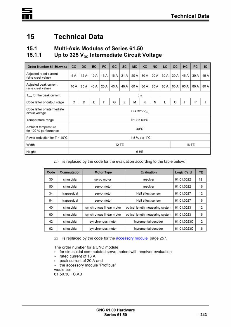
� Technical Data
CNC 61.00 Hardware
Series 61.50 - 243 -
15 Technical Data
15.1 Multi-Axis Modules of Series 61.50
15.1.1 Up to 325 VDC Intermediate Circuit Voltage
Order Number 61.50.nn.xx CC DC EC FC GC ZC MC KC NC LC OC HC PC IC
Adjusted rated current(sine crest value)
5 A 12 A 12 A 16 A 16 A 21 A 20 A 30 A 20 A 30 A 30 A 45 A 30 A 45 A
Adjusted peak current(sine crest value)
10 A 20 A 40 A 20 A 40 A 40 A 60 A 60 A 80 A 80 A 60 A 60 A 80 A 80 A
Tmax
for the peak current 3 s
Code letter of output stage C D E F G Z M K N L O H P I
Code letter of intermediatecircuit voltage
C = 325 VDC
Temperature range 0°C to 60°C
Ambient temperaturefor 100 % performance
40°C
Power reduction for T > 40°C !1.5 % per 1°C
Width 12 TE 16 TE
Height 6 HE
nn is replaced by the code for the evaluation according to the table below:
Code Commutation Motor Type Evaluation Logic Card TE
30 sinusoidal servo motor resolver 61.01.0022 12
50 sinusoidal servo motor resolver 61.01.0022 16
34 trapezoidal servo motor Hall effect sensor 61.01.0027 12
54 trapezoidal servo motor Hall effect sensor 61.01.0027 16
40 sinusoidal synchronous linear motor optical length measuring system 61.01.0023 12
60 sinusoidal synchronous linear motor optical length measuring system 61.01.0023 16
42 sinusoidal synchronous motor incremental decoder 61.01.0023C 12
62 sinusoidal synchronous motor incremental decoder 61.01.0023C 16
xx is replaced by the code for the accessory module, page 257.
The order number for a CNC module< for sinusoidal commutated servo motors with resolver evaluation< rated current of 16 A< peak current of 20 A and< the accessory module “Profibus”would be:61.50.30.FC.AB

�Technical Data
CNC 61.00 Hardware
- 244 - Series 61.50
15.1.2 Up to 560 VDC Intermediate Circuit Voltage
Order Number 61.50.nn,xx CF DF EF FF GF KF LF HF IF
Adjusted rated current(sine crest value)
5 A 8 A 8 A 12 A 12 A 15 A 15 A 22 A 22 A
Adjusted peak current(sine crest value)
10 A 20 A 40 A 20 A 40 A 60 A 80 A 60 A 80 A
Tmax
for the peak current 3 s
Code letter of output stage C D E F G K L H I
Code letter of intermediatecircuit voltage
F = 560 VDC
Temperature range 0°C to 60°C
Ambient temperaturefor 100 % performance
40°C
Power reduction for T > 40°C !1.5 % per 1°C
Width 12 TE 16 TE
Height 6 HE
nn is replaced by the code for the evaluation according to the table below:
Code Commutation Motor Type Evaluation Logic Card TE
30 sinusoidal servo motor resolver 61.01.0022 12
50 sinusoidal servo motor resolver 61.01.0022 16
34 trapezoidal servo motor Hall effect sensor 61.01.0027 12
54 trapezoidal servo motor Hall effect sensor 61.01.0027 16
40 sinusoidal synchronous linear motor optical length measuring system 61.01.0023 12
60 sinusoidal synchronous linear motor optical length measuring system 61.01.0023 16
42 sinusoidal synchronous motor incremental decoder 61.01.0023C 12
62 sinusoidal synchronous motor incremental decoder 61.01.0023C 16
xx is replaced by the code for the accessory module, page 257.
The order number for a CNC module< for sinusoidal commutated servo motors with resolver evaluation< rated current of 12 A< peak current of 20 A and< the accessory module “Profibus”would be:61.50.30.FF.AB

� Technical Data
CNC 61.00 Hardware
Series 61.50 - 245 -
15.1.3 Power Module 26.50.65x
LThe power module 26.50.65 replaces the power module 26.50.42and is fully downward compatible. It may be mounted into existingsystems.
The power module 26.50.42, however, is not completely upwardcompatible, since the compatibility depends on the system wiring.Contact SIEB & MEYER in this case.
Power Module 26.50.65 PS 16/50
Main supply: Voltage Range B C CZ* H I K
3 × each 70 VAC
+10 % –20%
230 VAC
+10 % –20%
380 VAC
to 480 VAC
+10% –5 %280 V
AC
+10 % –20%
250 VAC
+10% –20 %
Logic supply same potential as main supply, but only two phases
Rated direct current in the intermediatecircuit, ventilated with fan EL 1.23.1
16 A
Peak direct current in the intermediatecircuit, provided max. 1 s
50 A
Intermediate circuit voltage 100 VDC
+10 % –20%
325 VDC
+10 % –20%
540 VDc
bis 680 VDC
+10 % –5 %
400 VDc
+10 % –20%
350 VDc
+10 % –20%
Minimum ballast resistor 5 S 10 S 5.6 S
Temperature range 5°C to 60°C100 % rated current up to 40°C
Reduction of the rated current at ambienttemperatures > 40°C
!1,5 % per 1°C
Width 14 TE = 71.1 mm
Height 6 HE = 264 mm
* power module without overvoltage protection
Power Ranges of the Power Module 26.50.65
Voltage range B C CZ H I K
Main supply 1.4 kW 7.0 kW 10.0 kW 5.5 kW 7.0 kW
Logic supply 100 W 180 W 150 W 150 W 150 W
LWhen rating the drive it has to be considered that the rated cur-rents and peak currents of the power module (intermediate circuitcurrents) are not comparable to the currents of the servo module(currents to the AC motor). See also “Electric Performance Dimen-sioning”, page 265.

�Technical Data
CNC 61.00 Hardware
- 246 - Series 61.50
15.1.4 Back Planes
Multi-Axis Modules of Series 61.50
Order Num-
berMounting As
Impossible Accessory Modu-
lesTE
61.01.0004 swing frame AA, AB, AE, AF, AG, AH, G1 12
61.01.0018 wall mounting A1, AA, AG, AH, D1, F1, G1, 12
61.01.0037 swing frame A1, F1, G1 12
61.01.0038 wall mounting AG, AH, G1 12
61.01.0053 wall mounting A1, F1 12
61.01.0058 swing frame A1, F1 12
61.01.0060 swing frame AA, AB, AE, AF, AG, AH 12
Power Module 26.50.65x
Swing Frame
14 TE
Wall Mounting
14 TE
Order Number61.01.001761.01.0061
26.50.0078

� Technical Data
CNC 61.00 Hardware
Series 61.50 - 247 -
15.2 Compact Modules of Series 61.50
Order Number 061.50.nn.Ax.XX
061.50.nnBx.XX 061.50.nn.Cx.XX
Adjusted rated current (sine crest value) 7 A 7 A 10 A
Adjusted peak current (sine crest value) 10 A 20 A 40 A
Tmax
for the peak current 3 s
Code letter of output stage A B C
Temperature range 0°C to 60°C
Ambient temperature for 100 % performance 40°C
Power reduction for T > 40°C !1.5 % per 1°C
Width 16 TE
Height 6 HE
nn is replaced by the code for the evaluation according to the table below:
Code Commutation Motor Type Evaluation Logic Card TE
11 sinusoidal servo motor resolver 61.01.0022 16
15 trapezoidal servo motor Hall effect sensor 61.01.0027 16
21 sinusoidal synchronous linear motor optical lenght measuring system 61.01.0023 16
23 sinusoidal synchronmotor incremental decoder 61.01.0023C 16
x Code letter for the intermediate circuit voltage
C 150 VDC to 325 VDC; 1.80 kW; supply 3 × 110 VAC to 3 × 230 VAC;+10 %
D 48 VDC to 80 VDC; 0.36 kW; supply 3 × 34 VAC to 3 × 56 VAC
XX is replaced by the code for the accessory module, page 257.
The order number for a CNC module< for sinusoidal commutated servo motors with resolver evaluation< rated current of 7 A< peak current of 20 A< an intermediate circuit voltage of 325 VDC and< the accessory module “Profibus”would be:61.50.11.BC.AB
15.2.1 Back Planes
Order Number Mounting AsImpossible Accessory Modu-
lesTE
61.01.0019 wall mounting AA, G1 16
61.01.0028 swing frame G1 16
61.01.0051 swing frame A1, F1 16

�Technical Data
CNC 61.00 Hardware
- 248 - Series 61.50
61.01.0057 wall mounting A1, AA, AB, AE, AF, D1, F1 16

� Technical Data
CNC 61.00 Hardware
Series 61.50 - 249 -
15.3 Module Identification
61.50 xx. x x. xx
Accessory module
Voltage range
Current range
Module type
CNC 61.00 series
Example
61.50 30. D C. VL
Accessory module VL:A1 INTERBUS interfaceB4 Angle pulse input/output 5 VF1 MODLINK interface
Intermediate circuit voltage up to 325 VDC
12 A rated current20 A peak current
Multi-axis module: Control of sinusoidal com-mutated motors with resolver evaluation,width 12 TE
CNC 61.00 series

�Technical Data
CNC 61.00 Hardware
- 250 - Series 61.50

� Dimensioned Drawings
CNC 61.00 Hardware
Series 61.50 - 251 -
16 Dimensioned Drawings
16.1 Front View of Swing Frame Mounting
16.2 Top View of Swing Frame Mounting
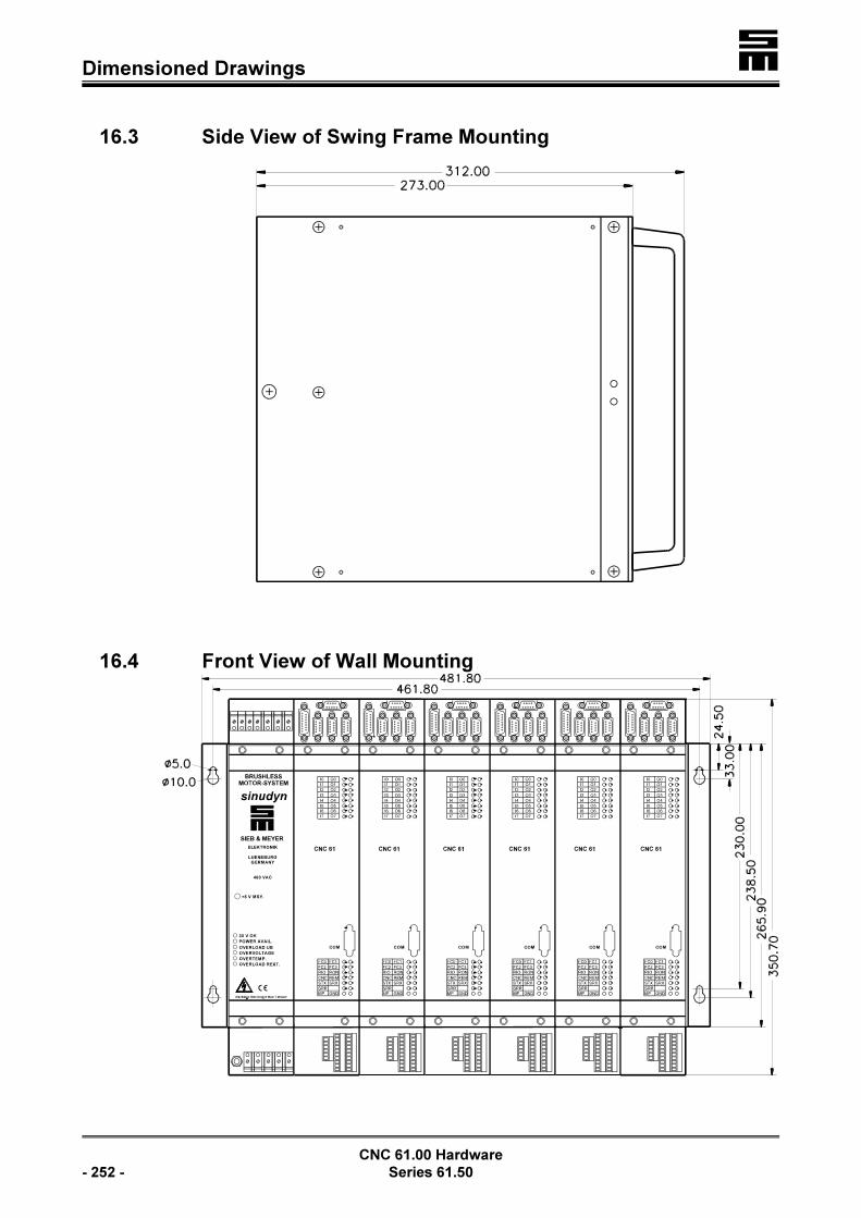
�Dimensioned Drawings
CNC 61.00 Hardware
- 252 - Series 61.50
16.3 Side View of Swing Frame Mounting
16.4 Front View of Wall Mounting

� Dimensioned Drawings
CNC 61.00 Hardware
Series 61.50 - 253 -
16.5 Top View of Wall Mounting
16.6 Side View of Wall Mounting
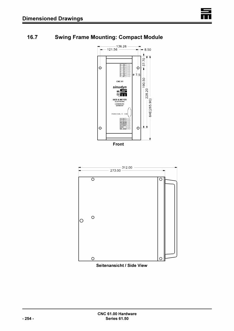
�Dimensioned Drawings
CNC 61.00 Hardware
- 254 - Series 61.50
16.7 Swing Frame Mounting: Compact Module

� Dimensioned Drawings
CNC 61.00 Hardware
Series 61.50 - 255 -
16.8 Wall Mounting: Compact Module

�Dimensioned Drawings
CNC 61.00 Hardware
- 256 - Series 61.50

� Accessories
CNC 61.00 Hardware
Series 61.50 - 257 -
17 Accessories
17.1 Accessory Modules
Code Accessory Module Order Number Socket
A1 INTERBUS interface 026.44.0056
A A2 Second serial interface 026.44.0073
A3 Transducer interface 026.44.0053A
A4 Analog input module 026.44.0053B
A5 Transducer and second serial interface 026.44.0067AAB1
A6 Analog input module and second serial interface 026.44.0067B
AA Transducer and two serial interfaces 061.01.009
AAB Profibus-DP interface 061.01.0012
AE Transducer and Profibus-DP interface 061.01.0033
AF Active transducer and Profibus-DP interface 061.01.0033A
AGPassive twin transducer, 2 serial interfaces, Profibus inter-face and angle pulse input 5 V
061.01.0043/.0049AB1
AHActive twin transducer, 2 serial interfaces, Profibus interfaceand angle pulse input 5 V
061.01.0043/.0044
B1 Interface for incremental encoder 5 V 061.01.0020B1
B
B2 Interface for incremental encoder 24 V 061.01.0020B2
B3 Angle pulse output module 5 V 061.01.0020B3
B4 Angle pulse output and input 5 V 061.01.0020B4
B5 Angle pulse input module, 2-fold, with 5 V level 061.01.0020B5
B7 Counter input and angle pulse output 5 V 061.01.0020B7
B8 Counter input and angle pulse output 5 V 061.01.0020B8
B9 Angle pulse input module, 2-fold, with 5 V/24 V levels 061.01.0020B9
BA Angle pulse input 24 V/angle pulse output 5 V 061.01.0020BA
C1 I/O expansion interface 026.44.0054 C
C2SSI interface, comprising the I/O expansion interface, aninput for an incremental encoder with 5 V level and an inputfor an absolute value encoder
026.44.0079A
BC2
C3SSI interface, comprising the I/O expansion interface, aninput for an incremental encoder with 24 V level and an in-put for an absolute value encoder
026.44.0079B
C4 SSI interface, I/O expansion and angle pulse output 5 V 061.01.0035
D1 CAN Bus interface 026.44.0055 D
E1 battery-buffered RAM and real time clock 026.44.0065 E
F1 MODLINK interface F3
G1 ETHERNET interface 061.01.0042 G3
LThe modules A3, A4, B1, B2, B3 and C1 can be used for all backplanes.

�Accessories
CNC 61.00 Hardware
- 258 - Series 61.50
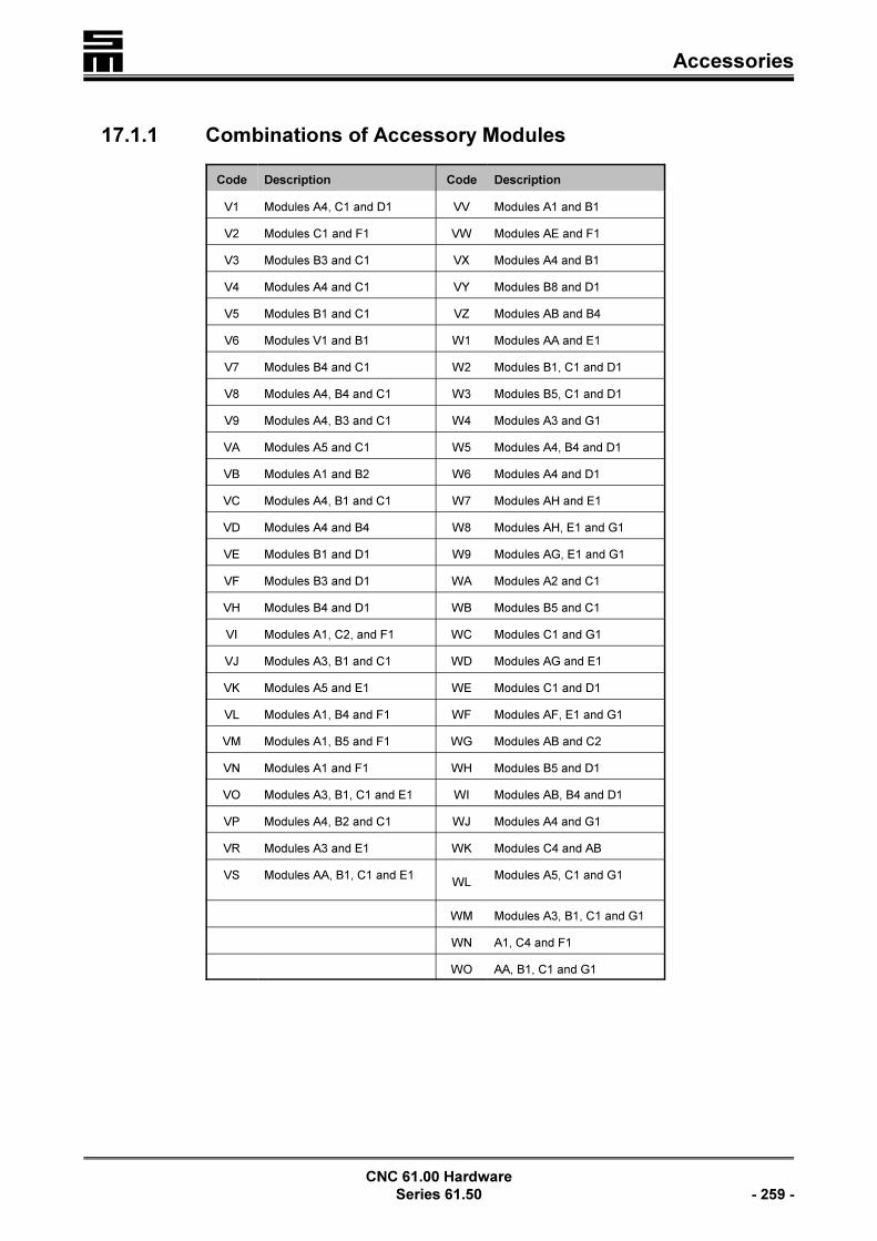
� Accessories
CNC 61.00 Hardware
Series 61.50 - 259 -
17.1.1 Combinations of Accessory Modules
Code Description Code Description
V1 Modules A4, C1 and D1 VV Modules A1 and B1
V2 Modules C1 and F1 VW Modules AE and F1
V3 Modules B3 and C1 VX Modules A4 and B1
V4 Modules A4 and C1 VY Modules B8 and D1
V5 Modules B1 and C1 VZ Modules AB and B4
V6 Modules V1 and B1 W1 Modules AA and E1
V7 Modules B4 and C1 W2 Modules B1, C1 and D1
V8 Modules A4, B4 and C1 W3 Modules B5, C1 and D1
V9 Modules A4, B3 and C1 W4 Modules A3 and G1
VA Modules A5 and C1 W5 Modules A4, B4 and D1
VB Modules A1 and B2 W6 Modules A4 and D1
VC Modules A4, B1 and C1 W7 Modules AH and E1
VD Modules A4 and B4 W8 Modules AH, E1 and G1
VE Modules B1 and D1 W9 Modules AG, E1 and G1
VF Modules B3 and D1 WA Modules A2 and C1
VH Modules B4 and D1 WB Modules B5 and C1
VI Modules A1, C2, and F1 WC Modules C1 and G1
VJ Modules A3, B1 and C1 WD Modules AG and E1
VK Modules A5 and E1 WE Modules C1 and D1
VL Modules A1, B4 and F1 WF Modules AF, E1 and G1
VM Modules A1, B5 and F1 WG Modules AB and C2
VN Modules A1 and F1 WH Modules B5 and D1
VO Modules A3, B1, C1 and E1 WI Modules AB, B4 and D1
VP Modules A4, B2 and C1 WJ Modules A4 and G1
VR Modules A3 and E1 WK Modules C4 and AB
VS Modules AA, B1, C1 and E1WL
Modules A5, C1 and G1
WM Modules A3, B1, C1 and G1
WN A1, C4 and F1
WO AA, B1, C1 and G1

�Accessories
CNC 61.00 Hardware
- 260 - Series 61.50
17.2 External I/O Expansion Modules
17.2.1 E/A Modules 44.20.xx
Order Num-
ber
Description
044.20.008 I/O module, 8 inputs and 8 outpus 24 V, cannot be cascaded, with flat connector
044.20.008B I/O module, 8 inputs and 8 outputs 24 V, cannot be cascaded, with Submin D con-nector
044.20.012 I/O basic module for the I/O modules 044.20.014/.013/.053/.028
044.20.014 Input module, 16 inputs, 24 V
044.20.013 Output module, 16 outputs, 24 V
044.20.0028 Output module, 8 outputs, 24 V, 1 A each
044.20.0051 Output module, 8 outputs, 24 V
044.20.0053 Outputs module, 8 outputs, 24 V, 1 A each
17.2.2 I/O Modules 50.06
Module Designation Function Components
50.06.1x
Basic module I/O50.06.0200.x50.06.0500.x with up to 64 physical connections
50.06.2x
50.06.3x
50.06.1xx Expansion module I/O 50.06.0500.x with up to 64 physical connections
50.06.2xxBasic module I/Owith customized PCB
50.06.0200.x50.06.0500.x with up to 56 physical connections50.06.01xx.x with up to 8 physical connections
50.06.3xxBasic module B(bidirectional)
50.06.0200.x50.06.0500.x with up to 64 bidirectional physical connections
50.06.4xxExpansion module B(bidirectional)
50.06.0500.x with up to 64 bidirectional physical connections
50.06.5xxBasic module B(bidirectional) with customized PCB
50.06.0200.x50.06.0500.x with up to 56 bidirectional physical connections50.06.01xx.x with up to 8 physical connections
50.06.10xx reserved
50.06.12xx reserved
50.06.20xx reserved
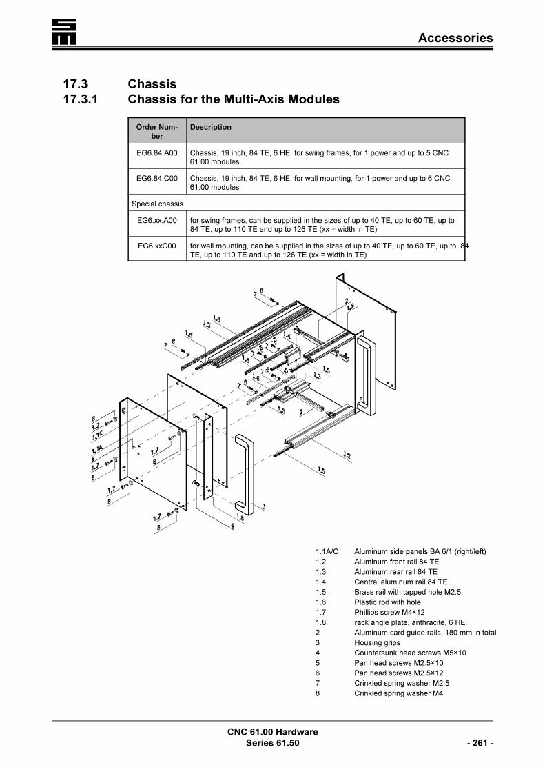
� Accessories
CNC 61.00 Hardware
Series 61.50 - 261 -
17.3 Chassis
17.3.1 Chassis for the Multi-Axis Modules
Order Num-
ber
Description
EG6.84.A00 Chassis, 19 inch, 84 TE, 6 HE, for swing frames, for 1 power and up to 5 CNC61.00 modules
EG6.84.C00 Chassis, 19 inch, 84 TE, 6 HE, for wall mounting, for 1 power and up to 6 CNC61.00 modules
Special chassis
EG6.xx.A00 for swing frames, can be supplied in the sizes of up to 40 TE, up to 60 TE, up to84 TE, up to 110 TE and up to 126 TE (xx = width in TE)
EG6.xxC00 for wall mounting, can be supplied in the sizes of up to 40 TE, up to 60 TE, up to 84TE, up to 110 TE and up to 126 TE (xx = width in TE)
1.1A/C Aluminum side panels BA 6/1 (right/left)
1.2 Aluminum front rail 84 TE
1.3 Aluminum rear rail 84 TE
1.4 Central aluminum rail 84 TE
1.5 Brass rail with tapped hole M2.5
1.6 Plastic rod with hole
1.7 Phillips screw M4×12
1.8 rack angle plate, anthracite, 6 HE
2 Aluminum card guide rails, 180 mm in total
3 Housing grips
4 Countersunk head screws M5×10
5 Pan head screws M2.5×10
6 Pan head screws M2.5×12
7 Crinkled spring washer M2.5
8 Crinkled spring washer M4

�Accessories
CNC 61.00 Hardware
- 262 - Series 61.50
9 Fixing hole for the grounding
17.3.2 Chassis for the Compact Modules
Order Number Description
EG6.16.5A Chassis, 19 inch, 6 HE, for swing frames
EG6.15.5C Chassis, 19 inch, TE, 6 HE, for wall mounting
1 4 × 12 raised fillister head screw, DIN 7985, zinc coated
2 4.3 mm spring washer, DIN 137, zinc coated
3 2.6 mm spring washer, DIN 137, zinc coated
4 2.5 × 12 raised fillister head screw, DIN 7985, zinc coated
5 Isolating rod 84 TE
6 Threaded rod M2.5, 147.32 mm web
7 2.5 × 10 raised fillister head screw, DIN 7985, zinc coated
8 Rear profile, 6 HE, 147.32 mm hole
9 BA 6/16 side element, wall-mounted mains filter, 266 mm
10 Card guide rail, 6 HE, 161.50 mm
11 Front profile, 147.32 mm hole
12 Central profile, 6 HE, 147.32 mm
13 BA 6/22 side element, 6 HE, left

� Accessories
CNC 61.00 Hardware
Series 61.50 - 263 -
17.4 Blind Front Panels
If not all spaces are equipped with CNC 61.00 modules in a 19 inch chassis, the gapscan be covered with blind front panels.
Width Order Number
2 TE F06.02.00.00
4 TE F06.04.00.00
8 TE F06.08.00.00
12 TE F06.12.00.01
14 TE F06.12.00.00

�Accessories
CNC 61.00 Hardware
- 264 - Series 61.50
� Electric Performance Dimensioning
CNC 61.00 Hardware
Series 61.50 - 265 -
18 Electric Performance Dimensioning
Experience shows that questions arise during the dimensioning of a drive whenselecting output stages and power supplies. This chapter shall make clear thephysical background and shall help to correctly dimension the electronic components.
18.1 Components
18.1.1 Output Stage
The output stage of a servo amplifier is specified by the following details:
Voltage RangeThe maximum intermediate circuit voltage is limited by the used transistors and ca-pacitors and the minimum space between the circuit-board conductors.
Components have an electric strength of 600 VDc at output stages with a max. ad-missible intermediate circuit voltage of 325 VDC (class C), that means: at an AC supp-ly of 230 VAC. The reserve is necessary to preclude damages at surge voltages andto protect the higher intermediate circuit voltages during the deceleration.
Current RangeThe current range specifies the max. admissible currents. Distinction is made bet-ween peak and rated current:< The peak current is only admissible for a short time (mostly 5 seconds) and de-
pends on the used transistors and their number.< The rated current can be provided continuously by the output stage. Its value
depends on the cooling of the transistors, that means: the capacity of the usedheatsink and its ventilation.
18.1.2 Power Supply
The power supply is specified by the following details:
Voltage RangeThe maximum voltage supply is limited by the used transistors, diodes and capaci-tors and the minimum space between the circuit-board conductors.

�Electric Performance Dimensioning
CNC 61.00 Hardware
- 266 - Series 61.50
Current RangeThe current range specifies the max. admissible currents. Distinction is made bet-ween peak and rated current:< The peak current is only admissible shortly (mostly 1 second) and depends on
the used diodes and their number.< The rated current can be provided continuously by the power supply. Its value
depends on the cooling of the diodes, that means: the capacity of the used heat-sink and its ventilation.
CapacityIn practice, a maximum permanent power is specified, since the supply voltage isassumed to be constant. Since the limitation in the power supply is determined by theload carrying capacity of the diodes, the maximum permanent power depends on thesupply voltage and the type of supply.
Examples:Supply 230 VAC
, 2 phases, max. permanent current of diodes 6 A230V 2 6 A = 2.76 kWAC × ×
Supply 400 VAC, 3 phases, max. permanent current of diodes 6 A400V 3 6 A = 7.20 kWAC × ×
The maximum peak current depends on the diode type.
The protection is calculated as follows:Capacity
Supply
2,76kW
230V12A
Ac
r.m. s= =
18.1.3 Motor
Among other things, the motor is specified by the following details:
Peak CurrentThe peak current defines the max. admissible motor current. The peak current is onlyadmissible for short times (between 1 and 30 seconds) and depends on the usedmotor material and the thickness of the coil wires. The motor manufacturer normallyspecifies the peak current for standstill and the rotating field. Normally, the specifica-tions are r.m.s. values.
Rated CurrentThe rated current can permanently impressed to the motor. Its value depends on themotor cooling, the coils and the max. admissible motor temperature. The motor ma-nufacturer normally specifies the rated current for standstill and the rotating field.Normally, the specifications are r.m.s. values.

� Electric Performance Dimensioning
CNC 61.00 Hardware
Series 61.50 - 267 -
Voltage ConstantDue to the underlying inductance, the motor generates during the operation a negati-ve field voltage, which is opposite to the provided voltage. This voltage is propor-tional to the speed and is specified in volt per 1,000 revolutions. The specificationsare normally r.m.s. values and are measured between the connection terminals.
Example:Intermediate circuit voltage: 325 V, e.m.f.: 100 V /1,000 revs.
Only 225 V are provided per 1000 RPM for controlling the motor. The motor has thetheoretical max. speed of 3,250 RPM. At this speed no torque is provided, since acurrent cannot be impressed.
Torque ConstantThe torque constant specifies the ratio between the motor current and the motor tor-que (Nm/A). The torque constant is the result of required the max. speed, the dyna-mics, the efficiency and the quality of the magnet material.
Inductive Coil ResistanceThe inductive coil resistance (TL) results from the number of windings of the coil. Itis zero during the standstill. The resistance increases with the frequency.
Ohmic Coil ResistanceThe ohmic coil resistance R results from the length and thickness of the wires. Duringthe standstill only it specifies the coil resistance.
Electric Time ConstantThe electric time constant results from the ohmic and the inductive resistance (J =L/R)
Nut Setting MotorsNut setting motors usually are high dynamic, with high peak speed, high peak torque,low mass inertia and low rated torque. As a result, the voltage constant and inductan-ce are low, the wires of the coil are thin and the rotor diameter is small. Due to thelow inductance, nut setting motors are operated with a high pulse width modulation(PWM frequency 16 kHz) to keep the current ripple low.

�Electric Performance Dimensioning
CNC 61.00 Hardware
- 268 - Series 61.50
18.2 Power Consumption of a Drive
If a constant torque is taken from the drive, the power consumption will depend onthe actual speed.
Examples:Preset torque: 30 NmIntermediate circuit voltage: 300 VVoltage constant: 50 V / 1,000 RPMCoil resistance: 1 STorque constant: 1 Nm / A
From this results a motor current of
I30Nm
1Nm A30A= =
/
The motor requires a voltage of U = 1 S × 30 A = 30 V
0 RPM, StandstillFrom this results a power of P = 30 V × 30 A = 0.9 kWAt an intermediate circuit voltage of 300 V an input current results from the supplyvoltage of I = P / 300 V = 3 AThus, in the power supply considerably less current flows than in the motor. Thisreflection is very important especially for nut setting applications, since the high tor-ques and currents are only required for low speeds.
2,000 RPMAt 2,000 RPM the motor requires a voltage of U = R × I + e.m.f. × n = 1 S × 30 A +50 V / (1,000 RPM) × (2,000 RPM) = 130 V.From this results a power of P = 130 V × 30 A = 3.9 kW.At an intermediate circuit voltage of 300 V an input current results from the supplyvoltage of I = P / 300 V = 13 A.In the power supply thus a considerable higher current flows at 2,000 RPM than atstandstill.
5,400 U/minAt 5,400 RPM the motor requires a voltage of U = R × I + e.m.f × n = 1 S × 30 A +50 V /(1,000 RPM) × (5,400 RPM) = 300 V.From this results a power of P = 300 V × 30 A = 9 kW.At an intermediate voltage of 300 V an input current results from the supply voltageof I = P / 300 V = 30A.The identical current value thus flows in the power supply at 5,400 RPM than in themotor.
It must be considered, that the currents, flowing in the motor phases, are lower byfactor %3 than the currents, calculated above.
The examples clearly show that the expected motion profile must be considered forthe dimensioning of the power module. An exact dimensioning is only possible byintegrating the motion profile.
This also applies for the dimensioning of the output stage and the motor.

� Electric Performance Dimensioning
CNC 61.00 Hardware
Series 61.50 - 269 -

�Electric Performance Dimensioning
CNC 61.00 Hardware
- 270 - Series 61.50

� Appendix: Revisions
CNC 61.00 Hardware
Series 61.50 - 271 -
19 Appendix: Revisions
The appendix describes alterations, made in comparison to the version with theidentification number “061-cnc-tec61.50/r1-sm-en-hg/ca” of October 6, 1997.
Identification Number “061-cnc-tec61.50/r2-sm-en-hg/ca”
of March 31, 1999
This technical manual has totally been revised. Worth mentioning are:< The insertion of new back planes< The insertion of new accessory modules< The omission of the technical data and order numbers as well as the dimensioned
drawings. This information can now be found in a separate manual.
Identification Number “061-cnc-tec61.50/r3-sm-en-hg/ca”
of October 22, 1999
Chapter “Safety Instruction and Application Advice”Section “Appropriate Use”: Supplement to the third paragraph.
Chapter “Wiring”Section “General Information”: The table regarding the conductor cross-sectionshas been deleted. A general information referring to the DIN EN 60204-1 hasbeen inserted.
Chapter “Back Planes” und “Pin Assignment”Both chapters have been combined to “Back Planes and “Pin Assignment”. Othersubdivision.The back plane 61.01.0038 has been inserted.
L The version r3 has never been published, since alterations came up
in the meantime. The above mentioned alterations are also valid for
version r4.
Identification Number “061-cnc-tec61.50/r4-sm-en-hg/ca”
of March 3, 2000
Chapter “Wiring”Section “Wiring of the 24 V (Internal/External)”: The drawing has been modified.
Chapter “Front Panels”The section “Front Panel of the Power Module 26.50.42xx” has been changed forthe upgraded power module 26.50.65.The section “STX / SRX / SRR - ...” has been revised.
Chapter “Back Planes and Pin Assignment”Section “X1 - Connection of First Measuring System (Feedback)”: The assignmentfor the evaluation with Hall sensors has been modified for all back planesl (excep-tion: power module).Additional assignment to the connection “X8 - Transducer Connection” for all backplanes, providing this connector.Additional assignment to the connection “X14 - Transducer/Analog Input” for allback planes, providing this connector.

�Appendix: Revisions
CNC 61.00 Hardware
- 272 - Series 61.50
Section “Back Planes of the Power Module ...” has been modified, since the powermodule 26.50.42 has been replaced by the power module 26.50.65.
Chapter “Accessory Modules”The accessory module AF has been added.
The chapter “Cables” has been added to the end of this technical manual.
Identification Number “061-cnc-tec61.50/R005-sm-de-hg/ca/ac”
of July 18, 2002
The hardware description has been revised completely. Worth mentioning are thefollowing alterations/additions:Section 8.4.2 "Possible Causes for an Error" has been added.Chapter 7 "Safeguard (Preventing Unintentional Start)": The figure has been revised.Section 10.14 "B - Universal Angle Pulse Module" has been revised.
Identification Number “061-cnc-tec61.50/R006-sm-de-hg/ca/ac/she”
of March 31, 2004
The chapter "Safeguard" has been deleted. The fuses in figure "Power Module Card 26.50.0038.xx/26.50.0073.xx" has beendescribed. The bus system "INTERBUS and MODLINK" has been added. 2 accessory modules of the bus connections X5 and X6 has been deleted.
Identification Number “061-cnc-tec61.50/R007-sm-de-hg/ca/ac/she”
of August 25, 2004
The table concerning the fuses on the card of the power module 26.50.0038.xx/26.50.0073.xx has been added.
Identification Number “061-cnc-tec61.50/R008-sm-de-hg/ca/ac/she/uh”
of April 04, 2013
Chapter 12.1.2: Cable pin assignment corrected.