Embed Size (px)
Citation preview

' $
COMPUTER NETWORKSCS 45201CS 55201
CHAPTER 2
Data Link Networks
P. Farrell / H. Peyravi
Department of Computer Science
Kent State University
Kent, Ohio 44242
http://www.cs.kent.edu/˜peyravi
Fall 2001
& %CS 4/55201: Computer Networks Fall 2001
' $
Contents
• Hardware Building Blocks
• Encoding
• Coding Design
• Framing
• Error Detection
• Reliable Transmission
• Ethernet
• FDDI
• Network Adaptors
& %CS 4/55201: Computer Networks Fall 2001

Chapter 2: Data Link Networks Hardware Building Blocks' $Hardware Building Blocks
Network Connecting Problems
� Physical connection (coax, fiber, ... )
� Encoding/Decoding data bits.
� Framing, packets, messages.
� Error detection.
� Reliable delivery despite errors.
� Media Access Control (MAC).
=⇒ These issues are implemented in the network adaptor
(board).
� =⇒ We will study the above problems in the context of
I Point-to-Point links
I Carrier Sense Multiple Access, CSMA networks (Ethernet)
I Token Rings, Fiber Distributed Data Interface
& %CS 4/55201: Computer Networks Fall 2001 1 of 47
Chapter 2: Data Link Networks Hardware Building Blocks' $
Network Nodes
� Assume a general-purpose (programmable) computer;
with special-purpose hardware.
to network
CPU
Memory
I/O Bus
Network Adapter
Cache
� A device driver manages the adaptor
� Finite memory (implies limited buffer space)
� Connects to network via a network adaptor
� Fast processor, slow memory
& %CS 4/55201: Computer Networks Fall 2001 2 of 47

Chapter 2: Data Link Networks Hardware Building Blocks' $
Network Links
� Links propagate signals
I Analog: continuous
I Digital: discrete
� Binary data are encoded in to
I Analog signals: modulator (modem)
I Digital signals: demodulator
� A digital transmitter transmits binary data over a digital link.
� full duplex links
� half duplex links
& %CS 4/55201: Computer Networks Fall 2001 3 of 47
Chapter 2: Data Link Networks Hardware Building Blocks' $
Data vs Signal
Digital
Analog
Digital
Digital
Digital
Digital
Analog
Analog Analog
Data Signal
Data
Medium Data
Signal
Telephone
Modem
CODEC
Transmitter
& %CS 4/55201: Computer Networks Fall 2001 4 of 47

Chapter 2: Data Link Networks Hardware Building Blocks' $
Some Physical Medium
Type Speed Distance
Category 5 twisted pair 10-100Mbps 100m
50-ohm coax (ThinNet) 10-100Mbps 200m
75-ohm coax (ThickNet) 10-100Mbps 500m
Multimode fiber 100Mbps 2km
Single-mode fiber 100-2400Mbps 40km
� Can be leased or owned
Standard Links
Type Bandwidth Applications
ISDN 64 Kbps for digital voice/data
T1 1.544 Mbps 24 64Kbps, old technology
T3 44.736 Mbps 30 T1
STS-1 51.840 Mbps sync. transfer signal optical
STS-3 155.250 Mbps for optical fiber
STS-12 622.080 Mbps for optical fiber
STS-24 1.244160 Gbps for optical fiber
STS-48 2.488320 Gbps for optical fiber
� The device that encodes analog voice into digital ISDN link is
called CODEC (coder/decoder).
� STS-N links are sometimes called OC-N (optical carrier).
� STS-N is used for electrical device connected to the link.
� OC-N is used for optical device connected to the link.
& %CS 4/55201: Computer Networks Fall 2001 5 of 47
Chapter 2: Data Link Networks Encoding' $Encoding
Overview
� Signals propagate over a physical medium.
I Digital signals
I Analog signals
� Data can be either digital or analog; we’re interested in digital
data.
� Problem: Encode the binary data that the source node wants to
send to the destination node into the signal that propagates over
Adapter Adaptersignal
bits
Node Node
signalling component
& %CS 4/55201: Computer Networks Fall 2001 6 of 47

Chapter 2: Data Link Networks Encoding' $
Maximum Data Rate of a Channel
I Nyquist (1924) stated that for a noise-free channel with
bandwidth W (Hz), and multilevel signaling M , the capacity
(bps) can be computed as
C = 2W log2 M
I Doubling W doubles the data rate.
I The presence of noise can corrupt one or more bits. If data
rate is increased, the bits become shorter , and more bits are
affected by a given noise pattern.
I At a given noise level, the higher the data rate, the higher the
error rate.
5v
0v
Bilevel Encoding
Multilevel Encoding (M=4)
& %CS 4/55201: Computer Networks Fall 2001 7 of 47
Chapter 2: Data Link Networks Encoding' $
Shannon’s Theorem
I Shannon (1948) developed a formula to identify the upper
bound on the channel capacity.
• The signal-to-noise ratio (S/N) is the ratio of power in a
signal to the power contained in the noise that is present at
a particular point in the transmission.
S/N = 10 log10
signal power
noise power
• The maximum channel capacity is computed as
C = B log2(1 +S
N)
where C is the capacity in bits per second and B is the
bandwidth in Hz.
I For example a noiseless 3-kHz channel cannot transmit binary
signals at a rate exceeding 6000 bps.
I A channel of 3000-Hz bandwidth, and a signal to thermal noise
of 30 dB can never transmit more than 30,000 bps.
= 30dB = 10 log10(S/N)
S/N = 1000
C = 3000 log2(1 + 1000) = 3000× 9.9673 < 30000bps
& %CS 4/55201: Computer Networks Fall 2001 8 of 47

Chapter 2: Data Link Networks Encoding' $
Coding Terminology
Pulse
Bit
0
-5v
+5v +5v
-5v
� Signal element: Pulse
� Modulation Rate: 1
Duration of the smallest element=Baud rate
� Data Rate: Bits per second
� Data Rate is a function of
I bandwidth
I signal/noise ratio
I encoding technique
& %CS 4/55201: Computer Networks Fall 2001 9 of 47
Chapter 2: Data Link Networks Encoding' $
Transmission Media
� Twisted Pair
I Unshielded Twisted Pair (UTP)
• Voice Grade: Telephone wire
• Data Grade: Better quality
=⇒ 100 Mbps over 50 m is possible
I Shielded Twisted Pair (UTP)
� Coaxial Cable
� Optical Fiber
I Modes:
index of reflection =Speed in vacuum
Speed in medium
I Single mode
I Multimode
& %CS 4/55201: Computer Networks Fall 2001 10 of 47

Chapter 2: Data Link Networks Coding Design' $Coding Design
Diff Manchester
NRZI
Manchester
Clock
NRZ
Bits+5v0
-5v
0 0 1 0 1 1 1 0 1 0 0 0 0 011
� Non-Return to Zero (NRZ)
I 1 = high level, 0 = low level
I Problem: consecutive 1s or 0s =⇒ Unable to recover clock
Uniform distribution of 1’s and 0’s tune the clocks
� Non-return to Zero Inverted (NRZI): Make a transition from the
current signal to encode a one, and stay at the current signal to
encode a zero; solves the problem of consecutive ones.
I 0 = no transition at beginning of interval (one bit at time)
I 1 = transition at beginning of interval
& %CS 4/55201: Computer Networks Fall 2001 11 of 47
Chapter 2: Data Link Networks Coding Design' $� Manchester:
I 0 = low to high
I 1 = high to low
� Differential Manchester
I 1 = absence of transition
I 0 = presence of transition
Always a transition in middle of interval =⇒ easy to synchronize
& %CS 4/55201: Computer Networks Fall 2001 12 of 47

Chapter 2: Data Link Networks Framing' $Framing
Overview
� Problem: Breaking sequence of bits into a frame
I Must determine first and last bit of the frame
I Typically implemented by network adaptor
I Adaptor fetches (deposits) frames out of (into) host memory
Adapter Adapterbits
frames
Node A Node B
& %CS 4/55201: Computer Networks Fall 2001 13 of 47
Chapter 2: Data Link Networks Framing' $
Byte-Oriented Protocols
� Sentinel Approach
I BISYNC(binary sync. comm.)
SY
N
Header
ST
X
Body
ET
X
CRC
SO
H
8 8 8 8 8 16
SY
N
I IMP-IMP (ARPANET)
SY
N
SY
N
Header
ST
X
Body
ET
X CRC
DLE
DLE
8 8 8 8 128 8 8 16
I Problem: ETX character might appear in the data portion of
the frame.
I Solution: Escape the ETX character with a DLE character in
BISYNC; escape the DLE character with a DLE character in
IMP-IMP.
� Byte Counting Approach (DDCMP)
SY
N
SY
N
Header Body CRC
Cla
ss Count
8 8 8 1614 42
I Problem: Count field is corrupted (framing error).
I Solution: Catch when CRC fails.
& %CS 4/55201: Computer Networks Fall 2001 14 of 47

Chapter 2: Data Link Networks Framing' $
Bit-Oriented Protocols
� HDLC: High-Level Data Link Control (also SDLC and PPP)
� Delineate frame with a special bit-sequence: 01111110
Header Body CRCBeginningSequence
EndingSequence
8 16 16 8
� Bit Stuffing
I Sender: any time five consecutive 1s have been transmitted
from the body of the message, insert a 0.
I Receiver: should five consecutive 1s arrive, look at next bit(s):
• if next bit is a 0: remove it
• if next bits are 10: end-of-frame marker
• if next bits are 11: error
& %CS 4/55201: Computer Networks Fall 2001 15 of 47
Chapter 2: Data Link Networks Framing' $
Clock-Based Framing
� SONET: Synchronous Optical Network
� ITU standard for transmission over fiber
� STS-1 (51.84 Mbps)
� Byte-interleaved multiplexing
� Each frame is 125µs long.
3 bytes 1 byte
9 rows
90 bytes
PathoverheadTransport
overhead
STS-1 Framce Structure
& %CS 4/55201: Computer Networks Fall 2001 16 of 47

Chapter 2: Data Link Networks Framing' $
Section
Terminals TerminalsTerminatingLightwave
EquipmentRegenarator Regenarator
EquipmentTerminatingLightwave
MuxSONET
MuxSONET
� � � � � � �� � � � � � � � � � � � � � �� � � � � � � �
� � � �� � � �� � � �� � � �� � � �� � � �� � � �� � � �� � � �
� � �� � �� � �� � �� � �� � �� � �� � �� � �� � � � �� � � � �� � � � �� � � � �� � � � �� � � � �� � � � �� � � � �� � � � �� � � � �� � � �� � � �� � � �� � � �� � � �� � � �� � � �� � � �� � � �� � � � � � � �� � � �� � � �� � � �� � � �� � � �� � � �� � � �� � � �
� � �� � �� � �� � �� � �� � �� � �� � �� � �
� � �� � �� � �� � �� � �� � �� � �� � �� � �
� � �� �� � �� �
� �� �
Path
� �� �
Line
� � � � �� � � � �
� � � � �� � � � �
� � � �� � � �� � � �� � � �
� � � � �� � � � �� � � � �� � � � �� � � � �� � � � �� � � � �� � � � �� � � � �� � � � �
� � � � �� � � � �� � � � �� � � � �� � � � �� � � � �� � � � �� � � � �� � � � �� � � � �
OC-12
! ! ! ! !" " " " "
STS-1
STS-1
STS-12STS-12
STS-3
STS-3
STS-3
T1
T1
T1
T3
T3
converterElectro-optical
Scrambler
STS-1
& %CS 4/55201: Computer Networks Fall 2001 17 of 47
Chapter 2: Data Link Networks Error Detection' $Error Detection
� Let Pb be the probability that a bit is in error
� Let F be the frame size in bits
Probability[frame has no error] = (1− Pb)F
Probability[one or more bits in error] = 1− (1− Pb)F
� Example: Let F=1000 bits and Pb = 10−6
Pr[frame is in error] = 1− (1− 10−6)1000 = 10−3
Parity Checks
0 1 2 3 4 5 6 7
1 0 1 1 0 1 1 Codeword
Odd parity 1 0 1 1 0 1 1 0 # of 1’s is odd
Even parity 1 0 1 1 0 1 1 1 # of 1’s is even
� Single error can be detected
& %CS 4/55201: Computer Networks Fall 2001 18 of 47

Chapter 2: Data Link Networks Error Detection' $
Check Digit Method
� Make the number divisible by 9
� Example: 823 to be sent
1. Left shift 823 =⇒ 8230
2. Divide by 9 and find remainder =⇒ 4
3. Subtract remainder from 9 =⇒ 9-4=5
4. Add the result of step 4 to step 1:8235
5. Check that the result is divisible by 9
� Detects all single-digit errors: 7235, 8335, 8255, 8237
� Detects several multiple-digit errors: 8765, 7346
� Does not detect some errors: 7335, 8775,
� Homework: Prove why it detects all single-digit errors
& %CS 4/55201: Computer Networks Fall 2001 19 of 47
Chapter 2: Data Link Networks Error Detection' $
Cyclic Redundancy Check
� Add k bits of redundant data to an n-bit message.
� Represent n-bit message as an n− 1 degree polynomial;
e.g., MSG=10011010 corresponds to M(x) = x7 + x4 + x3 + x1.
� Let k be the degree of some divisor polynomial C(x); e.g.,
C(x) = x3 + x2 + 1.
� Transmit polynomial P (x) that is evenly divisible by C(x), and
receive polynomial P (x) + E(x); E(x)=0 implies no errors.
� Recipient divides (P (x) + E(x)) by C(x); the remainder will be
zero in only two cases: E(x) was zero (i.e. there was no error), or
E(x) is exactly divisible by C(x).
I Choose C(x) to make second case extremely rare.
� Sender:
I multiply M(x) by xk; for our example, we get
x10 + x7 + x6 + x4 (10011010000);
I divide result by C(x) (1101);
I Send 10011010000 - 101 = 10011010101, since this must be
exactly divisible by C(x);
� Want to ensure that C(x) does not divide evenly into polynomial
E(x).
& %CS 4/55201: Computer Networks Fall 2001 20 of 47

Chapter 2: Data Link Networks Error Detection' $
1101110110011010000
1101
1101
MessageGenerator
1001
1000
11011100
1000
Remainder
11111001
1011
1101
1101
101
� What can be detected?
I All single-bit errors, as long as the xk and x0 terms have
non-zero coefficients.
I All double-bit errors, as long as C(x) has a factor with at least
three terms.
I Any odd number of errors, as long as C(x) contains the factor
(x + 1).
I Any ‘burst’ error (i.e sequence of consecutive errored bits) for
which the length of the burst is less than k bits.
I Most burst errors of larger than k bits can also be detected.
& %CS 4/55201: Computer Networks Fall 2001 21 of 47
Chapter 2: Data Link Networks Error Detection' $
Common polynomials for C(x)
CRC C(x)
CRC-8 x8 + x2 + x1 + 1
CRC-10 x10 + x9 + x5 + x4 + x1 + 1
CRC-12 x12 + x11 + x3 + x2 + 1
CRC-16 x16 + x15 + x2 + 1
CRC-CCITT x16 + x12 + x5 + 1
CRC-32 x32 + x26 + x23 + x22 + x16 + x12 + x11+
x10 + x8 + x7 + x5 + x4 + x2 + x + 1
� Ethernet and FDDI use CRC-32
Two-Dimensional Parity
0 1 2 3 4 5 6 7
0 1 0 1 0 0 1 1 ← parity bit
1 1 0 1 0 0 1 0
1 0 1 1 1 1 0 1
0 0 0 1 1 1 0 1
0 1 1 0 1 0 0 1
1 0 1 1 1 1 1 0
Parity byte 1 1 1 1 0 1 1 0
� 2D parity catches 1, 2, and 3-bit errors, and most 4-bit errors.
� Homework: Show this is true
& %CS 4/55201: Computer Networks Fall 2001 22 of 47

Chapter 2: Data Link Networks Error Detection' $
Internet Checksum Algorithm
� The third approach
� View message as a sequence of 16-bit integers.
� Add these integers together using 16-bit ones complement
arithmetic, and then take the ones complement of the result.
� That 16-bit number is the checksum.
� Unlike CRC, it doesn’t have very strong error detection property
� The algorithm is easier to implement
& %CS 4/55201: Computer Networks Fall 2001 23 of 47
Chapter 2: Data Link Networks Reliable Transmission' $Reliable Transmission
� Recover from corrupt frames
I Error Correction Codes (ECC); also called Forward Error
Correction (FEC)
I Acknowledgments and Timeouts; also called Automatic Repeat
request (ARQ)
� Delivers frames without errors, in proper order to network layer
Error Correction Mechanisms
� ACK/NAK: provide sender some feed-back about the other end
� Time-out: for the case when entire packet or ACK is lost
� Sequence numbers: to distinguish retransmissions
Automatic Repeat Request (ARQ)
� Error detection
� Acknowledgment
� Retransmission after timeout
� Negative acknowledgment
& %CS 4/55201: Computer Networks Fall 2001 24 of 47

Chapter 2: Data Link Networks Reliable Transmission' $
Data
Sender Receiver
time
ACK
NAK
Data
ARQ Scenarios
ACK
Frame
time
out
ACK
Sender Receiver
Sender Receiver
time
out
time
out
Sender Receiver
time
out
time
out
ACK
Sender Receiver
time
out
time
out
X
X
X
Frame
Frame
Frame
Frame
Frame
Frame
ACKACK
ACK
& %CS 4/55201: Computer Networks Fall 2001 25 of 47
Chapter 2: Data Link Networks Reliable Transmission' $
Stop-and-Wait
sender receiver
Frame 0
ACK 0
Frame 1
ACK 1
Frame 0
ACK 0
time
. . .
Problem: Keeping the pipe full.
Example: 1.5Mbps link × 45ms RTT = 67.5Kb (8KB). Assuming
frame size of 1KB, stop-and-wait uses about one-eighth of the link’s
capacity. Want the sender to be able to transmit up to 8 frames
before having to wait for an ACK.
& %CS 4/55201: Computer Networks Fall 2001 26 of 47

Chapter 2: Data Link Networks Reliable Transmission' $
Sliding Window
Idea: Allow sender to transmit multiple frames before receiving an
ACK, thereby keeping the pipe full. There is an upper limit on the
number of outstanding (un-ACKed) frames allowed.
sender receiver
time
. . .
. . .
& %CS 4/55201: Computer Networks Fall 2001 27 of 47
Chapter 2: Data Link Networks Reliable Transmission' $Sender:
� Assign sequence number to each frame (SeqNum)
� Maintain three state variables:
I send window size (SWS)
I last acknowledgment received (LAR)
I last frame sent (LFS)
� Maintain invariant: LFS - LAR ≤ SWS
SWS<−
LAR(Last Acknowledgement
Received)
LFS(Last Frame Sent)
. . . . . .
� When ACK arrives, advance LAR, thereby opening window
� Buffer up to SWS frames
& %CS 4/55201: Computer Networks Fall 2001 28 of 47

Chapter 2: Data Link Networks Reliable Transmission' $Receiver:
� Maintain three state variables:
I receive window size (RWS)
I last frame acceptable (LFA)
I next frame expected (NFE) or last frame received (LFR = NFE
- 1)
� Maintain invariant: LFA - LFR ≤ RWS or equivalently
LFA - NFE + 1 ≤ RWS
<−
. . . . . .
RWS
NFE(Next Frame
Expected)
LFA(Last FrameAccepted)
� Frame SeqNum arrives:
I if NFE ≤ SeqNum ≤ LFA −→ accept
I if SeqNum < NFE or SeqNum > LFA −→ discarded
� Send cumulative ACK
� Variations
I selective acknowledgements
I negative acknowledgements (NAK)
& %CS 4/55201: Computer Networks Fall 2001 29 of 47
Chapter 2: Data Link Networks Reliable Transmission' $Sequence Number Space
� SeqNum field is finite; sequence numbers wrap around
� Sequence number space must be larger than number of
outstanding frames
� SWS ≤ MaxSeqNum-1 is not sufficient
I suppose 3-bit SeqNum field (0..7)
I SWS=RWS=7
I sender transmit frames 0..6
I arrive successfully, but ACKs lost
I sender retransmits 0..6
I receiver expecting 7,0..5, but receives second incarnation of
0..5
� SWS < (MaxSeqNum+1)/2 is correct rule
� Intuitively, SeqNum “slides” between two halves of sequence
number space
& %CS 4/55201: Computer Networks Fall 2001 30 of 47

Chapter 2: Data Link Networks Reliable Transmission' $
Concurrent Logical Channels
� Multiplex several logical channels over a single point-to-point link;
run stop-and-wait on each logical channel.
� Maintain three bits of state for each channel:
I boolean saying whether the channel is currently busy
I sequence number for frames sent on this logical channel
I next sequence number to expect on this logical channel
� ARPANET supported eight logical channels over each ground link
(16 over each satellite link).
� Header for each frame included a 3-bit channel number and a
1-bit sequence number, for a total of 4 bits; same number of bits
as the sliding window protocol requires to support up to eight
outstanding frames on the link.
� Separates reliability from flow control and frame order.
& %CS 4/55201: Computer Networks Fall 2001 31 of 47
Chapter 2: Data Link Networks Ethernet' $Ethernet
Overview
� History
I Developed by Xerox PARC in mid-1970s
I Roots in Aloha packet-radio network
I Standardized by Xerox, DEC, and Intel in 1978
I Similar to IEEE 802.3 standard
� CSMA/CD
I carrier sense
I multiple access
I collision detection
� Bandwidth: 10Mbps and 100Mbps
� Problem: Distributed algorithm that provides fair access to a
shared medium
& %CS 4/55201: Computer Networks Fall 2001 32 of 47

Chapter 2: Data Link Networks Ethernet' $
Physical Properties
� Classical Ethernet (thick-net)
I maximum segment of 500m
I transceiver taps at least 2.5m apart
I connect multiple segments with repeaters
I no more than 2 repeaters between any pair of nodes (1500m
total)
I maximum of 1024 hosts
I also called 10Base5
. . .
. . .
. . .
. . .
� Alternative technologies
I 10Base2 (thin-net): 200m; daisy-chain configuration
I 10BaseT (twisted-pair): 100m; star configuration
& %CS 4/55201: Computer Networks Fall 2001 33 of 47
Chapter 2: Data Link Networks Ethernet' $
Frame Format
Body CRCPreamble DestAddr
SrcAddr Type Postamble
64 48 48 16 32 8
Addresses:
� Unique, 48-bit unicast address assigned to each adaptor
� Example: 8:0:2b:e4:b1:2
� Broadcast: all 1s
� Multicast: first bit is 1
Adaptor receives all frames; it accepts (passes to host):
� Frames addressed to its own unicast address
� Frames addressed to the broadcast address
� Frames addressed to any multicast address it has been
programmed to accept
� All frames when in promiscuous mode
& %CS 4/55201: Computer Networks Fall 2001 34 of 47

Chapter 2: Data Link Networks Ethernet' $
Transmitter Algorithm
If line is idle:
� Send immediately
� Upper bound message size of 1500 bytes
� Must wait 51µs between back-to-back frames
If line is busy:
� Wait until idle and transmit immediately
� Called 1-persistent (special case of p-persistent)
If collision:
� jam for 512 bits, then stop transmitting frame
� minimum frame is 64 bytes (header + 46 bytes of data)
� delay and try again
I 1st time: uniformly distributed between 0 and 51.2µs
I 2nd time: uniformly distributed between 0 and 102.4µs
I 3rd time: uniformly distributed between 0 and 204.8µs
I give up after several tries (usually 16)
I exponential backoff
& %CS 4/55201: Computer Networks Fall 2001 35 of 47
Chapter 2: Data Link Networks Ethernet' $
Experiences
Observe in Practice
� 10-200 hosts (not 1024)
� Length shorter than 1500m (RTT closer to 5µ than 51µ)
� Packet length is bimodal
� High-level flow control and host performance limit load
Recommendations
� Do not overload (30% utilization is about max)
� Implement controllers correctly
� Use large packets
� Get the rest of the system right (broadcast, retransmission)
& %CS 4/55201: Computer Networks Fall 2001 36 of 47

Chapter 2: Data Link Networks FDDI' $FDDI
Overview
� Token Ring Networks
I PRONET: 10Mbps and 80 Mbps rings
I IBM: 4Mbps token ring
I 16Mbps IEEE 802.5/token ring
I 100Mbps Fiber Distributed Data Interface (FDDI)
� Basic Idea
I frames flow in one direction: upstream to downstream
I special bit pattern (token) rotates around ring
I must capture token before transmitting
I release token after done transmitting
• immediate release
• delayed release
I remove your frame when it comes back around
I stations get round-robin service
& %CS 4/55201: Computer Networks Fall 2001 37 of 47
Chapter 2: Data Link Networks FDDI' $
Physical Properties of FDDI
Dual Ring Configuration
(a) (b)
Single and Dual Attachment Stations
UpstreamNeighbor
DownstreamNeighbor
Concentrator (DAS)
SAS
� Each station imposes a delay (e.g., 50ns)
� Maximum of 500 stations
� Upper limit of 100km (200km of fiber)
� Uses 4B/5B encoding
� Can be implemented over copper (CDDI)
& %CS 4/55201: Computer Networks Fall 2001 38 of 47

Chapter 2: Data Link Networks FDDI' $
Timed Token Algorithm
� Token Holding Time (THT): upper limit on how long a station
can hold the token.
� Token Rotation Time (TRT): how long it takes the token to
traverse the ring.
TRT ≤ ActiveNodes × THT + RingLatency
� Target Token Rotation Time (TTRT): agreed-upon upper bound
on TRT.
� Algorithm
I each node measures TRT between successive arrivals of the
token
I if measured TRT > TTRT, then token is late so don’t send
data
I if measured TRT < TTRT, then token is early so OK to send
data
I define two classes of traffic
• synchronous data: can always send
• asynchronous data: can send only if token is early
I worse case: 2×TTRT between seeing token
I not possible to have back-to-back rotations that take 2×TTRT
time
& %CS 4/55201: Computer Networks Fall 2001 39 of 47
Chapter 2: Data Link Networks FDDI' $
Token Maintenance
� Lost Token
I no token when initializing ring
I bit error corrupts token pattern
I node holding token crashes
� Generating a Token (and agreeing on TTRT)
I execute when join ring or suspect a failure
I each node sends a special claim frame that includes the
node’s bid for the TTRT
I when receive claim frame, update bid and forward
I if your claim frame makes it all the way around the ring:
• your bid was the lowest
• everyone knows TTRT
• you insert new token
� Monitoring for a Valid Token
I should see valid transmission (frame or token) periodically
I maximum gap = ring latency + max frame ≤ 2.5ms
I set timer at 2.5ms and send claim frame if it fires
& %CS 4/55201: Computer Networks Fall 2001 40 of 47
Chapter 2: Data Link Networks FDDI' $
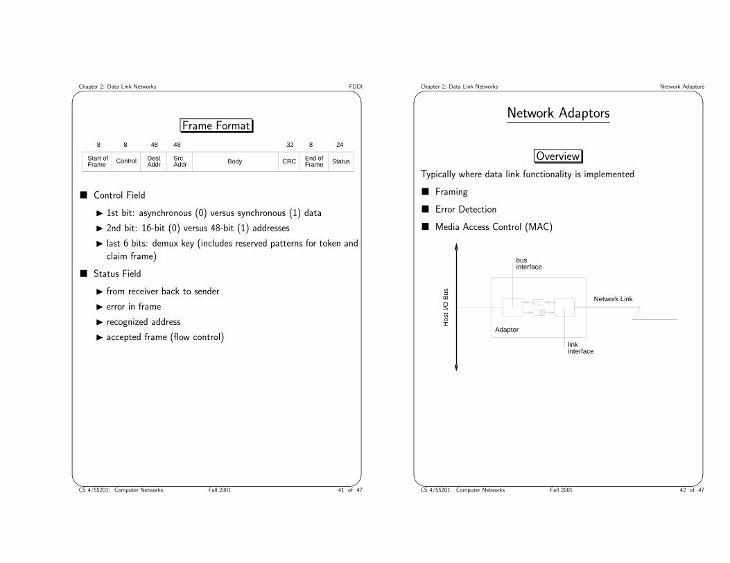
Frame Format
Body CRCDestAddr
SrcAddr
Start ofFrame Control End of
Frame Status
8 48 48 32 2488
� Control Field
I 1st bit: asynchronous (0) versus synchronous (1) data
I 2nd bit: 16-bit (0) versus 48-bit (1) addresses
I last 6 bits: demux key (includes reserved patterns for token and
claim frame)
� Status Field
I from receiver back to sender
I error in frame
I recognized address
I accepted frame (flow control)
& %CS 4/55201: Computer Networks Fall 2001 41 of 47
Chapter 2: Data Link Networks Network Adaptors' $Network Adaptors
Overview
Typically where data link functionality is implemented
� Framing
� Error Detection
� Media Access Control (MAC)
Hos
t I/O
Bus
Adaptor
Network Link
businterface
linkinterface
& %CS 4/55201: Computer Networks Fall 2001 42 of 47

Chapter 2: Data Link Networks Network Adaptors' $
Host Perspective
Control Status Register (CSR)
� Available at some memory address
� CPU can read and write
� CPU instructs Adaptor (e.g., transmit)
� Adaptor informs CPU (e.g., receive error)
Example
LE_RINT 0x0400 Received packet Interrupt (RC)
LE_TINT 0x0200 Transmitted packet Interrupt (RC)
LE_IDON 0x0100 Initialization Done (RC)
LE_IENA 0x0040 Interrupt Enable (RW)
LE_INIT 0x0001 Initialize (RW1)
& %CS 4/55201: Computer Networks Fall 2001 43 of 47
Chapter 2: Data Link Networks Network Adaptors' $
Moving Frames Between Host and Adaptor
Direct Memory Access (DMA)
BufferDescriptorList
. .
.
Memory Buffers
100
1400
1500
1500
1500
Programmed I/O (PIO)
Adapter Adaptersignal
bits
Node Node
signalling component
& %CS 4/55201: Computer Networks Fall 2001 44 of 47

Chapter 2: Data Link Networks Network Adaptors' $
Device Driver
Interrupt Handler
interrupt_handler()
{
disable_interrupts();
/* some error occurred */
if (csr & LE_ERR)
{
print_and_clear_error();
}
/* transmit interrupt */
if (csr & LE_TINT)
{
csr = LE_TINT | LE_INEA;
semSignal(xmit_queue);
}
/* receive interrupt */
if (csr & LE_RINT)
{
receive_interrupt();
}
enable_interrupts();
return(0);
}
& %CS 4/55201: Computer Networks Fall 2001 45 of 47
Chapter 2: Data Link Networks Network Adaptors' $Transmit Routine:
transmit(Msg *msg)
{
char *src, *dst;
Context c;
int len;
semWait(xmit_queue);
semWait(mutex);
disable_interrupts();
dst = next_xmit_buf();
msgWalkInit(&c, msg);
while ((src = msgWalk(&c, &len)) != 0)
copy_data_to_lance(src, dst, len);
msgWalkDone(&c);
enable_interrupts();
semSignal(mutex);
return;
}
& %CS 4/55201: Computer Networks Fall 2001 46 of 47

Chapter 2: Data Link Networks Network Adaptors' $Receive Interrupt Routine
receive_interrupt()
{
Msg *msg, *new_msg;
char *buf;
while (rdl = next_rcv_desc())
{
/* create process to handle this message */
msg = rdl->msg;
process_create(ethDemux, msg);
/* msg eventually freed in ethDemux */
/* now allocate a replacement */
buf = msgConstructAllocate(new_msg, MTU);
rdl->msg = new_msg;
rdl->buf = buf;
install_rcv_desc(rdl);
}
return;
}
& %CS 4/55201: Computer Networks Fall 2001 47 of 47


![ACRONYMS - The University of Texas at Arlington – UT ... · Web viewSome differences in HEVC [1][2] are coding tree units instead of macro blocks, single entropy coding methods-Context](https://img.dokumen.tips/doc/110x75/5b3b3cd07f8b9ace408c75e7/acronyms-the-university-of-texas-at-arlington-ut-web-viewsome-differences.jpg)


