Embed Size (px)
Citation preview

Budapest University of Technology and EconomicsFaculty of Electrical Engineering and Informatics
Department of Measurement and Information Systems
Bálint Ferencz
Hardware Assisted IEEE ClockSynchronization Under Linux
Master’s Thesis
Supervisors
Tamás Kovácsházy Dr.Dept. of Measurement and Inf. Systems
Zoltán FodorIntel Hungary
Budapest,


Hallgatói Nyilatkozat
Alulíro Ferencz Bálint, szigorló hallgató kijelentem, hogy ezt a diplomatervet meg nemengede segítség nélkül, saját magam készíteem, csak a megado forrásokat (szak-irodalom, eszközök stb.) használtam fel. Minden olyan részt, melyet szó szerint, vagyazonos értelemben, de átfogalmazvamás forrásból átveem, egyértelműen, a forrás meg-adásával megjelöltem.
Hozzájárulok, hogy a jelen munkám alapadatait (szerző(k), cím, angol és magyar nyelvűtartalmi kivonat, készítés éve, konzulens(ek) neve) a BME VIK nyilvánosan hozzáférhetőelektronikus formában, amunka teljes szövegét pedig az egyetem belső hálózatán keresz-tül (vagy autentikált felhasználók számára) közzétegye. Kijelentem, hogy a benyújtomunka és annak elektronikus verziója megegyezik. Dékáni engedéllyel titkosíto diplo-matervek esetén a dolgozat szövege csak év eltelte után válik hozzáférhetővé.
Budapest, . május .
Ferencz Bálint
hallgató

Contents
Abstract 1
Kivonat 3
List of terminology 5
1 Introduction 71.1 Motivation . . . . . . . . . . . . . . . . . . . . . . . . . . . . . . . . . . . . 7
1.2 Analysis of problem statement . . . . . . . . . . . . . . . . . . . . . . . . . 8
1.3 Standards and technologies involved . . . . . . . . . . . . . . . . . . . . . 9
1.3.1 Brief summary about the time metrics . . . . . . . . . . . . . . . . . 9
1.3.2 Overview of IEEE 1588 . . . . . . . . . . . . . . . . . . . . . . . . . . 9
1.3.3 Overview of the timekeeping in Linux . . . . . . . . . . . . . . . . . 13
1.3.4 GPS in high precision clock synchronization . . . . . . . . . . . . . 14
2 Proposed system hierarchy 172.1 Reference time/frequency source . . . . . . . . . . . . . . . . . . . . . . . 17
2.2 Network interface card . . . . . . . . . . . . . . . . . . . . . . . . . . . . . 19
2.2.1 Time stamping requirements . . . . . . . . . . . . . . . . . . . . . . 19
2.2.2 Role of the NIC in master clocks . . . . . . . . . . . . . . . . . . . . 20
2.2.3 Role of the NIC in slave clocks . . . . . . . . . . . . . . . . . . . . . 20
2.3 PHC API . . . . . . . . . . . . . . . . . . . . . . . . . . . . . . . . . . . . . 21
2.4 PTP daemon . . . . . . . . . . . . . . . . . . . . . . . . . . . . . . . . . . . 22
2.5 PPS subsystem . . . . . . . . . . . . . . . . . . . . . . . . . . . . . . . . . 23
2.6 Local network . . . . . . . . . . . . . . . . . . . . . . . . . . . . . . . . . . 24
3 Implementation and usage details 253.1 Cloning the reference time . . . . . . . . . . . . . . . . . . . . . . . . . . . 25
3.1.1 Physical connection of the GPS receiver . . . . . . . . . . . . . . . . 25
3.1.2 Seing up the serial connection & the gpsd daemon . . . . . . . . . 27
3.1.3 Disciplining the time and frequency on network adapters . . . . . . 29
3.2 Distribution of time . . . . . . . . . . . . . . . . . . . . . . . . . . . . . . . 33
3.2.1 PTP services using linuxptp . . . . . . . . . . . . . . . . . . . . . . . 33
3.2.2 Supporting legacy equipment . . . . . . . . . . . . . . . . . . . . . . 35
4 Measurements and validation 374.1 Testing equipment & configuration . . . . . . . . . . . . . . . . . . . . . . 37
4.1.1 Reference clock for calibration & validation . . . . . . . . . . . . . . 37
4.1.2 Nodes for testing and remote development . . . . . . . . . . . . . . 38
4.1.3 Other active elements . . . . . . . . . . . . . . . . . . . . . . . . . . 39
4.2 Measurement methodologies & results . . . . . . . . . . . . . . . . . . . . 40
4.2.1 Measurement methods . . . . . . . . . . . . . . . . . . . . . . . . . 40
4.2.2 Calibration process . . . . . . . . . . . . . . . . . . . . . . . . . . . 40
4.2.3 Measurements with an active network element . . . . . . . . . . . . 48
5 Industrial applications and future directions 555.1 Common applications of packet based time synchronization . . . . . . . . 55
5.1.1 Usage in distributed measurement systems . . . . . . . . . . . . . . 55
5.1.2 Audio-video bridging . . . . . . . . . . . . . . . . . . . . . . . . . . 56
5.1.3 Financial systems . . . . . . . . . . . . . . . . . . . . . . . . . . . . 57
5.2 Further directions & conclusion . . . . . . . . . . . . . . . . . . . . . . . . 57
Acknowledgement 60
Köszönetnyilvánítás 61
List of figures II
References V
Appendix VIA.1 Obtaining the soware and source code . . . . . . . . . . . . . . . . . . . VI
A.1.1 igb–pps & utilites . . . . . . . . . . . . . . . . . . . . . . . . . . . . VI
A.1.2 Linuxptp . . . . . . . . . . . . . . . . . . . . . . . . . . . . . . . . . VI
A.1.3 Garmin setup utility . . . . . . . . . . . . . . . . . . . . . . . . . . . VI


Abstract
is thesis presents a solution for reliable and cost-effective implementation of a highaccuracy time synchronization system in Local Area Networks via the IEEE proto-col. Nowadays the necessity of sub-microsecond time synchronization is increasing inthe fields of distributed systems and multimedia systems. By the usage of the generalpurpose communication protocols such as Ethernet for synchronization, the cost andcomplexity can be lower compared to ordinary systems (e.g. via GPS and IRIG syncednodes).
ere are several current applications of high accuracy in–band clock synchronizationsuch as power substation automation, high frequency trader financial systems, telecommu-
nications, etc. is thesis shows a reliable solution for Linux based systems to aainthis goal. e Ethernet based multimedia systems provide a less complex and cost effec-tive alternative to the multimedia specific connections based systems by eliminating theproprietary and single-function connections (VGA, DVI, HDMI) with the help of packetbased clock synchronization.
e document systematizes the earlierworks in this field, and presents an IEEE –hard-ware time stamping based solution for the high accuracy i.e. sub-microsecond synchro-nization. A high accuracy clock output (PPS) is designed and presented in this work.is output can be used for the distribution of the correct time to other devices, whichcan’t use the PTP protocol stack, and it’s also used for the validation of the measure-ments.
Every clock sync system requires a high precision time source for the most accurate syn-chronization process. In the measurements, the demo system contains a high precisionGPS based PTP master clock hardware. e thesis also shows the design and implemen-tation issues of a substituting equipment.
e performance of the network routing/switching equipment is critical for the decentaccuracy. e tests of the system are performed with PTP & non PTP compliant switch-ing devices with variable loads to cover the largest real world application cases.


Kivonat
Napjaink egy nagy kihívása, hogy akár az asztali számítógépek, akár a szórakoztató-elektronikai berendezések esetén a meglevő általános célú kommunikációs protokollokfelhasználásával olyan óraszinkronizációs megoldásokat működtessünk, melyek segítsé-gével az ado végpont eloszto feldolgozási feladatot, vizualizációt, méréseket végez-het el. Az előbbi területet példázzák a különböző banki rendszerek, ahol a beérkezőtranzakciók számának növekedésével egyre nagyobb szerepet kap az, hogy a tranzak-ciókat sorba tudjuk rendezni, azok keletkezési idejének nagy pontosságú ismereténekalapján. Ugyancsak nagy pontosság szükséges a szórakoztató–elektronikai berendezé-sekben, amennyiben az dedikáltan multimédia adatok átvitelére szolgáló hagyományos(VGA, DVI, HDMI) csatlakozókat próbáljuk meg lecserélni általános célú kommunikáci-óra szolgáló — és ezért rugalmasabb — Ethernet alapú megoldásokra.
A dolgozatban a korábbi munkák rendszereze összefoglalása után egy olyan IEEE és Linux alapú hardveres időbélyegzéssel rendelkező megoldás kerül bemutatásra, mely-ben biztosítható a rendszerek óráinak μs-nél kisebb hibával történő együjárása. Azórák együjárásának validációja, valamint a belőlük származtatható szinkronizációt se-gítő jelek előállítása szintén kardinális kérdés, a dolgozat nagypontosságú Hz frekven-ciájú PPS jelek segítségével mutatja be a szover és hardverréteg alkalmasságát az effélenagyobb pontosságot megkövetelő méréstechnikai feladatokban történő alkalmazható-ságra.
A nagy pontosságú szinkronizáció előfeltétele egy jó minőségű mesteróra alkalmazása aszinkronizációs hálózatban. Ezt egyrészt egy célhardver segítségével biztosítjuk, mely aGPS segítségével állítja elő a saját pontos idejét, a dolgozat készítése során azonban célegy Linux alapú mesteróra létrehozása, mely egy külső illeszte GPS vevővel kommuni-kálva terjeszti a pontos időt a végpontok felé.
Ahhoz, hogy a megoldás a való életben alkalmazható legyen, szükséges egy kisebb há-lózat összeállítása, ahol az ideális körülményeken felül különböző terheléses próbákkalbizonyosodunk meg a rendszer alkalmazhatóságáról. A terheléses tesztek PTP kompa-tibilis és nem kompatibilis eszközök segítségével valósulnak meg, ezzel is biztosítva alehető legtöbb előforduló konfigurációt.
List of terminology
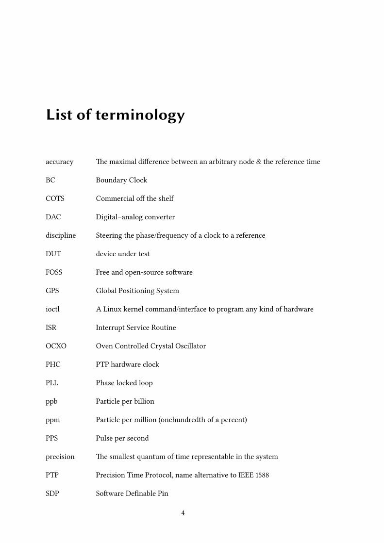
accuracy e maximal difference between an arbitrary node & the reference time
BC Boundary Clock
COTS Commercial off the shelf
DAC Digital–analog converter
discipline Steering the phase/frequency of a clock to a reference
DUT device under test
FOSS Free and open-source soware
GPS Global Positioning System
ioctl A Linux kernel command/interface to program any kind of hardware
ISR Interrupt Service Routine
OCXO Oven Controlled Crystal Oscillator
PHC PTP hardware clock
PLL Phase locked loop
ppb Particle per billion
ppm Particle per million (onehundredth of a percent)
PPS Pulse per second
precision e smallest quantum of time representable in the system
PTP Precision Time Protocol, name alternative to IEEE
SDP Soware Definable Pin
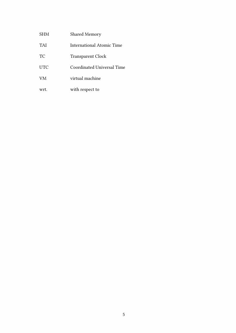
SHM Shared Memory
TAI International Atomic Time
TC Transparent Clock
UTC Coordinated Universal Time
VM virtual machine
wrt. with respect to

1 | Introduction
“A man with a watch knows what time it is. A man with two watches is never
sure.”
— Segal’s Law
1.1 Motivation
e emerging importance of maintaining a stable, accurate timebase in distributed sys-tems requires a supporting infrastructure to distribute the commonwall clock time to thenodes. e usage of the existing communication network makes these systems cheaperand less complex, therefore the expected reliability is higher and the administration over-head can be smaller.
Several solutions appeared in the past to satisfy the required functionality — the ven-erable NTP provides a widespread, reliable solution of the synchronization over In-ternet, but it doesn’t meet the most rigorous accuracy requirements. Distribution ofsub–microsecond accuracy timing informationwith out–of–band communication is avail-able long since; the U.S. originated GPS is among the most widespread solution to pro-vide reference time, but its indoor usage is limited. Vendors are selling proprietary solu-tions for solving the in–band time synchronization needs, but currently the open-sourcealternatives are covering only parts of the needed functionality.
e main goal of this thesis to introduce the main concepts behind the high accuracyclock synchronization in non-realtime systems, and to document the development & in-tegration of the necessary open-source components to build a high precision time sourcebased on PC architecture. e presented solution is based on GPS and the IEEE pro-tocol standard; it runs on Linux operating system.
I was introduced to concept of packet based time synchronization in when I chosemy first project laboratory topic. Back then there were several commercial solutionsto assemble PTP based synchronization networks. ere was an open–source applica-tion called PTPd [] which implemented the first IEEE standard’s master and slave
clock roles. My first task was to get comfortable with the basics of the PTP and get thePTPd daemon working with hardware time stamping capabilities — the main goal wasto discipline the kernel clock as good as possible.
In the following years a common API for controlling the NIC’s onboard clocks (PHC API
[]) were introduced along with a new linuxptp [] project. From that on a maintainedIEEE : compliant FOSS daemon were also available to use. e implementationeffort of high–quality and cheap computer based clocks becomes easier and easier, and Iwas involved in implementation and measurement of PTP based clock synchronizationsystems. is thesis is a natural evolution all of my previous findings about this subject.
1.2 Analysis of problem statement
e proposition of the thesis was to examine the current solutions of the PTP basedclock synchronization networks, and to propose a solution to aain sub-µs accuracytime synchronization with the usage of freely available soware tools and Intel networkinterface cards. In order to properly document the proposed tasks, I will organize thethis document in the following manner:
. e technologies behind the topic (IEEE , Linux time handling, GPS) will beintroduced to the reader.
. e general system hierarchy will be discussed with the identification of the rolesof the major building blocks — with the comparison of possible advantages/draw-backs.
. e implementation details of my work will be presented.
. e measurement results will be discussed before the conclusion.
. In the conclusion part I will introduce application scenarios of the product andsummarize most important findings in this document and the future ways of re-search.
I’ve focused on the maximum aainable accuracy with the usage of COTS componentsin PTP networks, the analysis of security problems are outside of the scope of this paper.
1.3 Standards and technologies involved
1.3.1 Brief summary about the time metrics
e meausurement of the flow of time dates back to the ancient civilizations who triedto formalize cyclic events of the days and years. e most apparent way of the time mea-surement was the counting of the sunrises and sunsets, but even the human perceptionspots the varying length of time between these events, and that is the most importantdrawback of empiric/astronomical definition of the unit of time. As science and technol-ogy advanced, beer and beer models and theories emerged about our world, whichimplied more precise definition of the time itself. e days derived from the observationof the sky were replaced by an exact physical phenomenon as the fundamental metric;nowadays the basic unit of time is the second, which is defined as ,,, cyclesof radiation corresponding to the transition between two hyperfine levels of the groundstate of cesium [].
e International Atomic Time (TAI) is a statistically derived unit based on the countingof the previously defined seconds with a large number of atomic clocks. e UniversalTime (UT, UT) is counted from hours at midnight, with unit of duration the meansolar day, defined to be as uniform as possible despite variations in the rotation of theEarth. e UT is the observed rotational time of an extraterrestrial point viewed froma fixed location on Earth and the UT is the corrected measurement of the former withthe irregularities of the Earth’s motion. Coordinated Universal Time (UTC) differs fromTAI by an integral number of seconds. UTC is kept within . seconds of UT by theintroduction of one-second steps to UTC, the “leap second”. To date these steps have al-ways been positive. UTC has replaced Greenwich Mean Time (GMT) as an internationalstandard [].
1.3.2 Overview of IEEE 1588
e IEEE standard describes a protocol which synchronizes computer clocks viaMulticast capable networks []. e protocol became standard in but it was revisedin ; the resulting update is not backwards compatiblewith the original version. Withproper hardware support the sub-microsecond synchronization accuracy is aainable inthe scope of local area networks. e recommended timescale of PTP is the same as TAI,which simplifies the implementation of the measurement systems. is timescale maybe changed to an arbitrary one (such as UTC), but several subprofiles forbid the usage ofother ones. e standard offers an automatic way for the configuration of the synchro-

nization network, based on the nodes preprogrammed capabilities. A synchronizationnetwork consists one or more of the following entities:
• Master clock
• Slave clock
• Boundary clock (optional)
• Transparent clock (optional)
Every clock synchronization network has at least one master, and one slave clock. Asynchronization network can be divided into several smaller separate domains wherethe synchronizing slaves obtain their wall time from discrete masters. Primary masterof the whole synchronization network is called grandmaster, the slaves and masters arealso called ordinary clocks. e synchronization algorithm supports two main modes offunction, the one step and two step synchronization. e masters of the network sendonly sync messages when they operate in one step synchronization mode, but they senda follow-up messages when not.
With the usage of the follow-upmessages, themaster can send the precise sending time ofthe sync packets to the slaves if it’s unable to inject this information in the sync packetson the fly. By sending follow-up messages the accuracy is improved with a negligibleincrease of the network traffic (Fig. ..). e slave nodes of the network capture theingress times of the sync packets. Now the offset from the master can be expressed as:
Δ𝑡 = 𝑇𝑠1 − 𝑇𝑚1 = 49 𝑠 (.)
Syn
c
Syn
c
Tm1 =
761 s
Tm2 =
762 s
t lin
e =
0.5
s
Ts3 =
762 s
Ts2 =
761 s
Ts1 =
712 s
Tm3 =
763 s
Fo
llo
w-u
pT
m1
Fo
llo
w-u
pT
m2
T’s1 =
712,5 s
T’s2 =
761,5 s
Figure 1.1: The offset correction algorithm
e applied offset corrections have constant error because the signalling delay is cur-rently disregarded. Estimation of the path delay is requested by the slaves via delay

request messages, the slave records the sending time of the packet, and the receive timeof the master’s delay response (Fig. ..). e master sends back the reception time of thedelay request package to the slave. It is assumed that the link delay is symmetrical, andit’s variance is low — this assumption is generally acceptable in local area networks, butin high accuracy systems the asymmetries of the system should be eliminated or compen-sated. e estimator of the delay is the mean of the master-to-slave and slave-to-masterpropagation times. In real world applications both the offset and delay calculations in-clude delicate filtering algorithms to cancel out the noise caused by the jier of timestamping, or the network delay.
Dela
y req
uest D
elay
res
po
nse
Tm
2
Tm1 =
1001 sTm2 =
1001,5 s
t lin
e =
0.5
s
Ts4 =
1003 s
Ts1 =
1000 s
Tm4 =
1003 sTm3 =
1002 s
Figure 1.2: The delay estimation algorithm
e autoconfiguration of the system is done with the Best Master Clock (BMC) algorithm.Every PTP port maintains a dataset about its capabilites, the most important fields are(in relative order of precedence):
• clockClass,
• clockAccuracy,
• offsetScaledLogVariance
• clockID.
e ClockID is the tie–breaker in the selection, its generated from the (presumably)unique MAC address of the adapter in most cases. If we measure the Allan deviationof the clock we can provide the offsetScaledLogVariance field, which describes thequantitative performance of the clock ([] pp. ). e clockAccuracy represents aninterval of maximum error compared to the reference time when the PTP port works asa grandmaster. e clockClass field represents the traceability of the time provided thePTP clock when it works as a grandmaster.
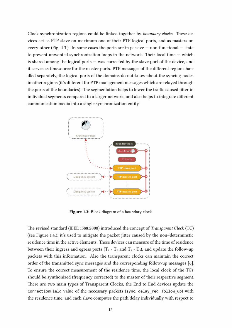
Clock synchronization regions could be linked together by boundary clocks. ese de-vices act as PTP slave on maximum one of their PTP logical ports, and as masters onevery other (Fig. ..). In some cases the ports are in passive — non-functional — stateto prevent unwanted synchronization loops in the network. eir local time — whichis shared among the logical ports — was corrected by the slave port of the device, andit serves as timesource for the master ports. PTP messages of the different regions han-dled separately, the logical ports of the domains do not know about the syncing nodesin other regions (it’s different for PTP management messages which are relayed throughthe ports of the boundaries). e segmentation helps to lower the traffic caused jier inindividual segments compared to a larger network, and also helps to integrate differentcommunication media into a single synchronization entity.
Boundary clock
PTP stack
Grandmaster clock
PTP slave port
PTP master port
PTP master port
Shared clock
Disciplined system
Disciplined system
Figure 1.3: Block diagram of a boundary clock
e revised standard (IEEE :) introduced the concept of Transparent Clock (TC)(see Figure ..); it’s used to mitigate the packet jier caused by the non–determinsticresidence time in the active elements. ese devices canmeasure of the time of residencebetween their ingress and egress ports (T₁ - T₂ and T₁ - T₃), and update the follow-uppackets with this information. Also the transparent clocks can maintain the correctorder of the transmied sync messages and the corresponding follow-up messages [].To ensure the correct measurement of the residence time, the local clock of the TCsshould be synthonized (frequency corrected) to the master of their respective segment.ere are two main types of Transparent Clocks, the End to End devices update theCorrectionField value of the necessary packets (sync, delay_req, follow_up) withthe residence time, and each slave computes the path delay individually with respect to

the grandmaster. With the usage of Peer to Peer Transparent Clocks, the slave ordinaryclocks can measure their direct path delays to their nearest TC. It means that everyactive node in the system computes the link delay to the nearest upstream port only,and the slave system doesn’t compute the link delay from the grandmaster, but uses thecumulated CorrectionField to estimate the link delay on the path.
Transparent clock
PTP stack
Grandmaster clock
PTP ingress port
PTP egress port
PTP egress port
Synthonized clock
Disciplined system
Disciplined system
T1
T2
T3
Figure 1.4: Block diagram of a transparent clock
1.3.3 Overview of the timekeeping in Linux
Like every operating system, Linux also has some sort of abstraction of time [][]. eoperating system is based on event–based principles, but the abstraction of the real time
is also present.
e Linux kernel time is represented by the jiffies counter on every architecture. Basedon the kernel seings the frequency of a jiffy — in terms of the real time — varies inthe range of milliseconds, therefore it cannot be used alone to measure events with highprecision. e incrementing jiffies represent the number of the timer interrupts of thesystem since the last boot. For example on x architecture, an integrated timestampcounter of the CPU used as a source of a more granular event scale. e jiffies countermeasure the elapsed cycles from the last boot, therefore the problem of the epoch han-dling should be also handled. It’s used to measure the distance between discrete eventsin the kernel, or provide time base for various system calls (e.g. select()) but it’s un-suitable to directly derive a precise representation of the real–world time from it.

e kernel specifies interfaces to estimate and query the real time of the call. In the Unixworld, time is measured on the UTC scale with the epoch of ˢᵗ of January , this isthe so called Unix time. e UTC time scale means that the problem of leap secondsshould be handled — there are Unix time seconds per day no maer how thetimescale varies. ere are several solutions to represent this kind of discontinuity inthe flow of time, one can add seconds to the time scale (aer minute’s ᵗʰ second the ˢᵗis inserted), repeat a second (like NTP does) or just increase the length of the seconds(time–smearing used by e.g. Google []). It is also problematic that the jiffies countergranularity if not enough to represent sub-millisecond time duration, but since Linux.. the introduction of high resolution timers (HRTs) solves the problem of such smallquantities with a common API.
Message based time synchronization needs an interface to query the transmit and receivetime of the synchronization data in a real-world timescale. e Linux kernel socketinterface supports the receive timestamping since the . kernel series (SO_TIMESTAMPor SO_TIMESTAMPNS – µs vs. ns timescale). e transmit timestamping is supportedthrough looping the sent packet back to the receive queue. In the SO_TIMESTAMPINGinterface were introduced to the Linux kernel, to enable the support of the hardwaretimestamping. In this case the send timestamps are looped back via the error queue of thesocket. e comparison of methods of the timestamping alternatives will be discussedlater.
1.3.4 GPS in high precision clock synchronization
e development of the Global Positioning System was driven by the military needs ofthe United States during the Cold War. e measurement of position originates in thehigh precision measurement of the radio signal propagation times from the satellites tothe receivers. To understand the connection between the time and position measure-ment, I will present the main ideas behind the system []. e layout of the systemconsists of three main parts — the Space Segment, the Control Segment and the UserSegment.
e Space Segment contains all of the GPS satellites, which are orbiting around the Earthin medium Earth orbit (approx. . km away, see Fig. ..). Each satellite has atomicclocks onboard to produce their own . MHz fundamental frequency. e satellitestransmit their data at two distinct microwave frequencies (L band at . MHz, Lband at . MHz). Both frequencies are created by multiplying the fundamentalfrequency with integer ratios (L – , L – ). By the usage of the two distinct fre-quencies, the ground equipment can measure the deviation of the propagation times,thus they reject the measurement noise caused by the propagation in the ionosphere
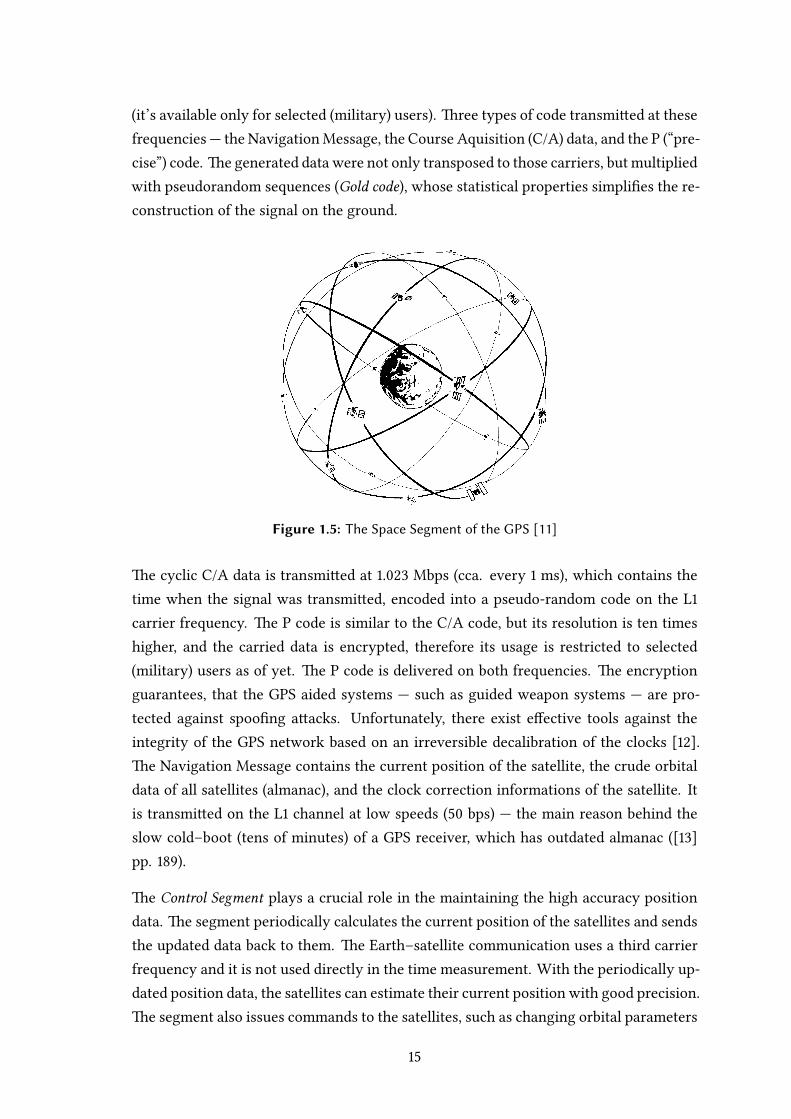
(it’s available only for selected (military) users). ree types of code transmied at thesefrequencies — the NavigationMessage, the Course Aquisition (C/A) data, and the P (“pre-cise”) code. e generated data were not only transposed to those carriers, but multipliedwith pseudorandom sequences (Gold code), whose statistical properties simplifies the re-construction of the signal on the ground.
Figure 1.5: The Space Segment of the GPS [11]
e cyclic C/A data is transmied at . Mbps (cca. every ms), which contains thetime when the signal was transmied, encoded into a pseudo-random code on the Lcarrier frequency. e P code is similar to the C/A code, but its resolution is ten timeshigher, and the carried data is encrypted, therefore its usage is restricted to selected(military) users as of yet. e P code is delivered on both frequencies. e encryptionguarantees, that the GPS aided systems — such as guided weapon systems — are pro-tected against spoofing aacks. Unfortunately, there exist effective tools against theintegrity of the GPS network based on an irreversible decalibration of the clocks [].e Navigation Message contains the current position of the satellite, the crude orbitaldata of all satellites (almanac), and the clock correction informations of the satellite. Itis transmied on the L channel at low speeds ( bps) — the main reason behind theslow cold–boot (tens of minutes) of a GPS receiver, which has outdated almanac ([]pp. ).
e Control Segment plays a crucial role in the maintaining the high accuracy positiondata. e segment periodically calculates the current position of the satellites and sendsthe updated data back to them. e Earth–satellite communication uses a third carrierfrequency and it is not used directly in the time measurement. With the periodically up-dated position data, the satellites can estimate their current position with good precision.e segment also issues commands to the satellites, such as changing orbital parameters
or selecting another onboard clock in case of failure.
e User Segment contains the soware and hardware systems of the observers. Ob-servers of the navigation messages can reconstruct their position bymeasuring the clockdifference of their equipment from the satellites’. At reception the reciever correlates theincoming signals to the locally generated reference signal. When the correct time dis-placement is found, the output of the correlator is near + and otherwise. e receivercan calculate the distance (pseudorange) from the satellites by using the clock differ-ences; its position is in the intersection of the calculated spheres. In simple models, theclock difference is encumbered by the errors of the satellite’s clock, and the deficienciesof the local clocks. Generally a clock reading can be split into two components:
. the actual state of the clock at time of reading,
. the clock bias, eg. the readout incertainities, propagation delay.
If we disregard the clock biases, the position could be approximated within reasonablebounds, but in precision clock synchronization systems those informations are invalu-able to reconstruct the satellites’ correct clock phase and frequency information. epseudorange calculation is sensitive to the error of the reconstructed clocks, thus deli-cate algorithms were developed to cancel the incertainities in the time synchronization.e GPS system uses the Composite Clock (CC) as its timescale, which is steered to theUTC time globally []. e CC is calculated from the average of the ground monitor-ing stations and the satellites onboard clock’s. e representation of time in the GPS iscounted in weeks and seconds within the week.
2 | Proposed system hierarchy
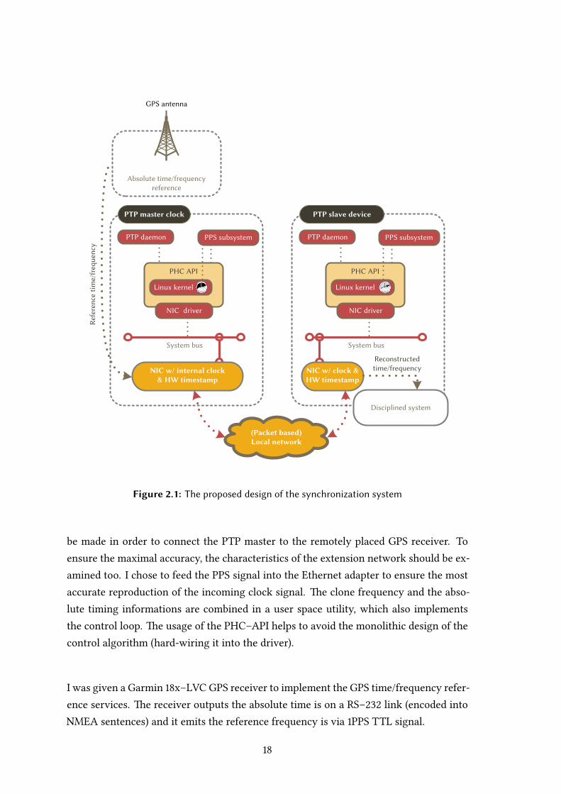
In this section the main components of the synchronization system will be discussed indepth (Fig. ..). e design of the network should suit the following requirements:
• At least µs accuracy (maximum difference between an arbitrary node and thegrandmaster)
• Configuration free design at run-time
• Compliance with the IEEE : standard
e system consists of three major components: the frequency reference, the PTP master
clock and the PTP slave clock(s). e detailed explanation of disciplined system is not inthe scope of this document but in the applications section some examples will be brieflyintroduced.
2.1 Reference time/frequency source
e primary goal of a clock synchronization system is to transfer the emied time andfrequency of the reference source to the synchronizing nodes. ese kinds of devicesare not deployable at every site in practice because of their high price (cesium atomicclocks), or their special placement requirements (GPS receivers need free view to thesky). Generally in larger clock distribution networks the direct distribution of the clocksignals into every node is impossible, thus a clock hierarchy was made to simplify theneeded cabling needs.
e most widespread high–quality reference clock source is the GPS, therefore, I choseit to provide the reference time to the masters of the synchronization system. e inter-face of the receivers are two–fold, the absolute timing information is available on somesort of serial/parallel signal, mostly transmied in the form of NMEA sentences and thephase/frequency information is transmied in a PPS signal. e placement of the re-ceiver is crucial; therefore, for indoor applications an extension of these signals should
Absolute time/frequencyreference
GPS antenna
(Packet based)Local network
PTP master clock
System bus
PTP daemon
NIC w/ internal clock& HW timestamp
PHC API
NIC driver
Linux kernel
PPS subsystem
PTP slave device
System bus
PTP daemon
NIC w/ clock & HW timestamp
PHC API
NIC driver
Linux kernel
PPS subsystem
Reconstructedtime/frequency
Disciplined system
Ref
eren
ce t
ime/
freq
uenc
y
Figure 2.1: The proposed design of the synchronization system
be made in order to connect the PTP master to the remotely placed GPS receiver. Toensure the maximal accuracy, the characteristics of the extension network should be ex-amined too. I chose to feed the PPS signal into the Ethernet adapter to ensure the mostaccurate reproduction of the incoming clock signal. e clone frequency and the abso-lute timing informations are combined in a user space utility, which also implementsthe control loop. e usage of the PHC–API helps to avoid the monolithic design of thecontrol algorithm (hard-wiring it into the driver).
I was given a Garmin x–LVC GPS receiver to implement the GPS time/frequency refer-ence services. e receiver outputs the absolute time is on a RS– link (encoded intoNMEA sentences) and it emits the reference frequency is via PPS TTL signal.
PTP port
ISR
OS network stack
In hardwareMAC
PHY
Physical link
Increasing precisionPTP
mes
sage
s
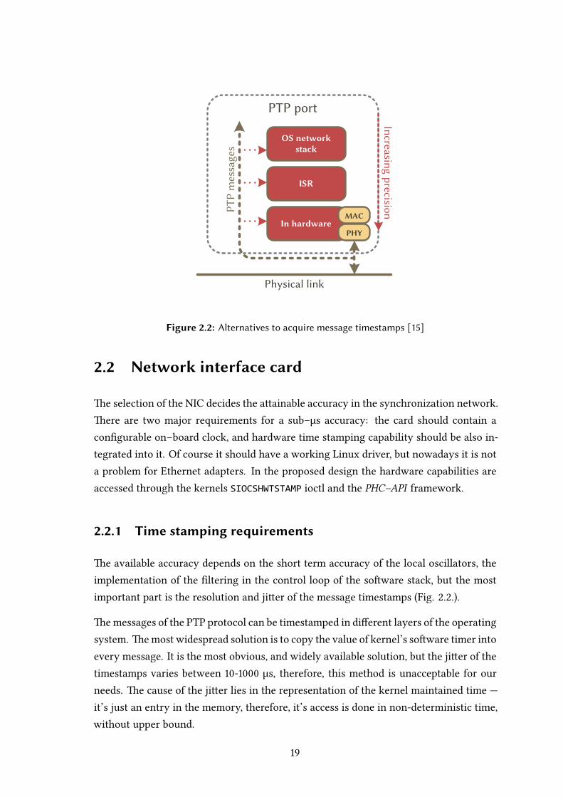
Figure 2.2: Alternatives to acquire message timestamps [15]
2.2 Network interface card
e selection of the NIC decides the aainable accuracy in the synchronization network.ere are two major requirements for a sub–µs accuracy: the card should contain aconfigurable on–board clock, and hardware time stamping capability should be also in-tegrated into it. Of course it should have a working Linux driver, but nowadays it is nota problem for Ethernet adapters. In the proposed design the hardware capabilities areaccessed through the kernels SIOCSHWTSTAMP ioctl and the PHC–API framework.
2.2.1 Time stamping requirements
e available accuracy depends on the short term accuracy of the local oscillators, theimplementation of the filtering in the control loop of the soware stack, but the mostimportant part is the resolution and jier of the message timestamps (Fig. ..).
emessages of the PTP protocol can be timestamped in different layers of the operatingsystem. emost widespread solution is to copy the value of kernel’s soware timer intoevery message. It is the most obvious, and widely available solution, but the jier of thetimestamps varies between - µs, therefore, this method is unacceptable for ourneeds. e cause of the jier lies in the representation of the kernel maintained time —it’s just an entry in the memory, therefore, it’s access is done in non-deterministic time,without upper bound.
Requesting of interrupts at every PTP message has lower jier than the previously men-tionedmethod, but it performswell only inmicrocontroller systemswhere fixed schedul-ing tables are available, but not in preemptively scheduled environments. e largenumber of the concurrent tasks & interrupts cause non–deterministic interrupt serviceperiods (tens of microseconds even on a Core Duo configuration).
e autonomous time stamping of packets is the only way to achieve the desired µsaccuracy in desktop applications. e independent time stamping cancels out most ofthe jiers and uncertainties of the measurements. e hardware time stamping can bedone in the adapter’s MAC and PHY layer, depending on the implementation. e usageof the local onboard clock is common in both methods. e MII, GMII, SGMII, etc. inter-connection between them can cause jier in the time stamps but it’s magnitudes smallerthan in the previously introduced methods. In my design, the selected Ethernet adapters(Intel i) has the message filtering and time stamping algorithms implemented in hard-ware and in its drivers too to decrease the load on the CPU. e hardware timestampsthe transmied messages when the global TX time stamping is enabled, and the packetdescriptor has the necessary flags active. e receive logic parses the packets in a con-figurable way, the hardware supports the IEEE–, and the IEEE–: standards(the laer is supported over UDP and Ethernet too). e message time stamping pointis defined at the last bit of the start–of–frame delimiter of the packet, the local clock islatched at every time stamping point.
2.2.2 Role of the NIC in master clocks
e local clock of network adapter should be disciplined to an external reference source.In my design, the network adapters have the necessary inputs to accurately clone theemied frequency of the reference, the time information is collected in RS– link andalso cloned into the on–board clock. To do so the driver and a user–space applicationshould be developed to incorporate the necessary discipline algorithms.
2.2.3 Role of the NIC in slave clocks
In most cases the synchronized local slave clocks should distributed to other devices,therefore, a local clock output should be implemented. With the usage of the networkadapter’s hardware output capabilities, the frequency information could be accuratelyreconstructed. e necessary timing information can be supplied in other ways (e.g.RS– link).

Clock driverA
Character device
User space code
(PTP daemon)
Class driver
Clock driverB
User space code
(PPS daemon)
User space
Kernel
Figure 2.3: The layout of the PHC API [2]
2.3 PHC API
is application programming interface serves as a simplified tool to access and programthe on–board clocks on the network adapters (Fig. ..). It was published to the developercommunity in and it was merged into the mainline kernel in (Linux ..). eexisting programs can use the PHC as a time source with small modifications.
e user-space application see the functionality of the clocks via a character device. esecharacter devices can be controlled with the previously used POSIX clock handling rou-tines, and the ordinary file manipulation functions. For example, the current time ofthe clock can be read with the clock_gettime() system call, and the read(), open(),poll() and ioctl() routines are also usable. e ioctl calls are used for requesting theancillary clock features which are not covered by the ordinary POSIX clock functions.
e character device is enumerated by the class driver which provides interfaces to thekernel driver developers to aach their implementation to the user–space. ere aretwo types of interface functions — the mandatory ones are the:
• query,
• set to arbitrary time,
• adjust with offset,
• and adjust the frequency of the clock.
ere’s a possibility to implement ancillary features of the clock served through thisinterface such as:
• program periodic output channels,
• provide a PPS hook for disciplining the local clocks,
• and time stamp external events.
e API supports an interface for implementing programmable periodic timers basedon the NIC clock, but currently nobody provided driver for it. With the usage of theancillary features a high quality master clock can be made with a clean, well–maintainedprogramming interface.
2.4 PTP daemon
e protocol stack implements the specified rules of the synchronization by the IEEE: standard, and implements the necessary unspecified functions too (e.g. disci-plines the clocks). In the past I used the PTPd soware to provide the needed function-ality. In the linuxptp daemon was published, and since the start of the writing ofmy thesis it evolved into a mature soware product.
e PTPd daemon was the first open–source implementation of the IEEE standard,and the base of the first open–source hardware assisted time stamping solutions. eoriginal code supported the soware time stamping only, but in the Intel releaseda proof of concept hardware time stamping capable fork of the daemon. My previouswork was based on the original code base, but some parts included some extra fixes andadvancements. Among the main features, the full implementation of ordinary clocks,and the portability & low resource usage are the most important. e lack of boundaryclock implementation means that this soware can only function in the endpoints ofthe synchronization network. e low resource usage means fixed point arithmetic inits filters and control loops, thus carefully designed and implemented algorithms areneeded to aain the accuracy requirements. e source code was wrien in C, so itruns on systems where the timestamping in the network stack is implemented. ePTP–API fork of the daemon breaks some of the original features (such as portability),but the clock discipline wouldwork on any adapter with refied drivers; therefore, it wasconsidered to include in this design. e fork was made by Richard Cochran, the maindeveloper of the linuxptp project; as the linuxptp evolved, the fork rendered obsolete andit’s removed from the internet. e usage of an unmaintained soware is not preferable

in any project, therefore, I chose a different daemon to include against the one stated inthe thesis proposal.
e linuxptp has a more active development community, and it’s goals fit in more in myapplication; therefore, I chose it as a replacement. It has the following features []:
• Supports hardware and soware time stamping via the Linux SO_TIMESTAMPING
socket option.
• Supports the Linux PTP Hardware Clock (PHC) subsystem by using theclock_gettime family of calls, including the new clock_adjtimex system call.
• Transport over UDP/IPv, UDP/IPv, and raw Ethernet (Layer ).
• Modular design allowing painless addition of new transports and clock servos.
• Implements Boundary Clock (BC) and Ordinary Clock (OC).
• Supports IEEE .AS– in the role of end station.
e soware’s target platform is Linux only, and relies on floating point operations;therefore, its portability is worse than PTPd’s. Compared to the vanilla PTPd, havingthe first four features are mandatory to enable the design of a high quality PTP masterclock. e daemon also implements Boundary Clock functions as opposed to PTPd. It’salso wrien in C language and its structure is well–suited for easy integration of alter-native transport layers or clock servos. e support of legacy time stamping and otherarchitectures are not the prime development factors.
2.5 PPS subsystem
e two–way communication between the on–board hardware clock and the kernel ismaintained by the PPS subsystem. It is used in two configurations, in the master anexternally generated event (the PPS signal of the GPS) is sampled and a PPS event istriggered to discipline the PHC and the kernel clocks. With the soware clock discipline,the base frequency of the soware control loop is also modified to ensure a more precisecorrection. It’s important that the on–board clock of the NIC should have PTP timescale(most likely), but the Unix time (and the kernel time also) based on UTC timescale, thisdifference should be known and corrected by the PPS daemon.
In slave systems the PPS events are used to correct the kernel time. In the earlier designs,the kernel clock was synchronized, but in case of hardware time stamping, the local time
base of network adapters should have transformed into the time base of the kernel, butthe tunable local clocks make this element unnecessary. e kernel clock discipline canbe donewith alternativemethods, for example the phc2sys utility bundled in the linuxptppackage offers an viable implementation with the usage of the kernel PPS subsystem.e separate tuning of the PTP device (network adapter) and the kernel clock is calledtwo layer synchronization. Generally the separate PTP clocks have beer stability, andaccuracy than the kernel clock, therefore, their usage is highly recommended.
2.6 Local network
e local network consists of active and passive elements working together with thesynchronization network. To aain the desired accuracy, the network should have aproper segmentation and hierarchy to ensure the lowest possible jier on the non–de-terministic Ethernet carrier. In real world configurations, the usage of Transparent andBoundary clocks are inevitable.
3 | Implementation andusagedetails
In this chapter, the actual implementation and setup details are discussed in depth. echosen parts will be examined in every reasonable aspect regarding the system’s accu-racy.
3.1 Cloning the reference time
e chosen Garmin receiver is suitable for testing the concept of the synchronization sys-tem, but it should be noted that its datasheet states that only µs accuracy is guaranteedunder a valid position fix (see [] pp. ). is upper bound of the error is guaranteed innon–stationary receivers too. It means that an arbitrary node in the PTP network mayhave more than µs error compared to the ideal GPS reference signal, therefore, the µsaccuracy can be guaranteed only within the bounds of synchronization system. ereare other commercially available GPS receivers which have beer specifications understationary usage, however the measurements described in the Section .. shows thatat good reception the desired goal is aainable.
3.1.1 Physical connection of the GPS receiver
In section . the drawbacks of the GPS was summarized briefly: “its indoor usage is lim-
ited”. During the construction of the system I have encountered with this problem, thusI needed a solution to connect the test computer in the server room with the remotelyplaced GPS receiver. In order to achieve the required accuracy, the interconnection hasto carry the asynchronous serial and PPS signals from the GPS module for meters. Inthe laboratory the power outlets are switched of for safety reasons every day, therefore,a remote power supply was also implemented.
e design and implementation of the circuit is made with the help of my advisor tosuccessfully overcome the suboptimal orientation of the server room.
GPS side
Signal delay measaurement
PSU
Master clock side
Galvanic isolation
USB
-Serial converter
(FT232R
)
GPS_RX
GPS_TX
PC_TX
PC_RX
GPS_PPS PPS_OUT
PPS_RET PPS_RET
TVS
En
cod
er
Pow
er
USB
PowerDC/DC
Garmin GPS receiver with TTL level serial and PPS output
GPS antenna
RJ-45
CATx
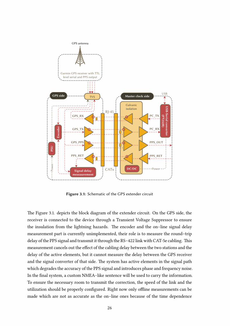
Figure 3.1: Schematic of the GPS extender circuit
e Figure .. depicts the block diagram of the extender circuit. On the GPS side, thereceiver is connected to the device through a Transient Voltage Suppressor to ensurethe insulation from the lightning hazards. e encoder and the on–line signal delaymeasurement part is currently unimplemented, their role is to measure the round–tripdelay of the PPS signal and transmit it through the RS– linkwith CAT-e cabling. ismeasurement cancels out the effect of the cabling delay between the two stations and thedelay of the active elements, but it cannot measure the delay between the GPS receiverand the signal converter of that side. e system has active elements in the signal pathwhich degrades the accuracy of the PPS signal and introduces phase and frequency noise.In the final system, a custom NMEA–like sentence will be used to carry the information.To ensure the necessary room to transmit the correction, the speed of the link and theutilization should be properly configured. Right now only offline measurements can bemade which are not as accurate as the on–line ones because of the time dependence
of temperature and other factors. e equipment is powered by a Power over Ethernetadapter on the GPS side.
On the master clock side, the connection is galvanically isolated from the rest of thesystem to ensure the lightning protection and electromagnetic compatibility. e PPSsignal can be looped back to enable the measurement of the signal delay. e serial linkis converted to USB to ensure the easy aachment to modern computers. e equipmentalso gains its power supply from the USB port. In the operating system the whole systemappears as a virtual serial device, which emits the NMEA sentences periodically.
3.1.2 Seing up the serial connection & the gpsd daemon
On the connected serial and PPS lines all of the necessary timing information is availableto accurately discipline the clock of the PTP master node. e serial line is connected tothe serial–USB converter; therefore, the Garmin receiver shows up as a generic USB tele-type device (/dev/ttyUSBx). Initially its serial port emits the messages with baud,so the receiving port should be configured to the same speed, otherwise only garbagewill appear on the screen! e properties of the receiver ($PGRMC) can be acquired byissuing the NMEA commands seen on the listing .).
Listing 3.1: erying the properties of the GPS module in console
onlab@mitpc37:~$ echo -en ’$PRGMCE\r\n’ > /dev/ttyUSB0
onlab@mitpc37:~$ cat /dev/ttyUSB0
$GPRMC,220553,A,4728.3435,N,01903.6016,E,000.0,000.0,040513,004.0,E*70
$GPGGA,220553,4728.3435,N,01903.6016,E,2,08,1.2,117.0,M,42.0,M,,*4A
$PGRMC,A,00117.0,100,0000000.000,000.000000000,0000,0000,0000,A,5,1,2,24,30.0*7E
^C
e section .. in the Garmin manual [] describes the available PPS/serial outputseings. Sometimes the receiver seems to be unresponsible to the commands issuedfrom Linux. e only circumvention of this problem was to aach it to a Windowsequipped PC and run the Garmin setup program on it (see Appendix A.). Aerwardsthe GPS module seems to be working as advertised. I have configured the receiver toemit % duty cycle PPS and bps serial output. To finish the setup, one shouldenable only the most important sentences on the receiver. is task can be done byissuing the $PGRMO command to the system (listing .). By default five sentences areenabled on the GPS x models, but the application needs only two, the $GPRMC and the$GPGGA sentences.

Listing 3.2: Enable the necessary NMEA sentences only
#!/bin/sh
# Disable all sentences
echo -en ’$PGRMO,,2\r\n’ > /dev/ttyUSB0
sleep 1
# Enable GPRMC and GPGGA
echo -en ’$PGRMO,GPRMC,1\r\n’ > /dev/ttyUSB0
sleep 1
echo -en ’$PGRMO,GPGGA,1\r\n’ > /dev/ttyUSB0
If the current seings were read out again from the device successfully, the initial set-tings are done. To extract the timing messages in a more friendly form, the gpsd wasused in this setup. e main advantage of this method is that the GPS device can beshared between different applications, and the clock discipline code is free from NMEAmessage parsing code, because the processing occurs in the gpsd. e client applica-tion can connect to the daemon via UNIX sockets and through a shared memory drivertoo. It should be noted that the SHM driver permits read only access only to the ex-tracted data. It is assumed that the daemon itself is installed somehow in the system —built from the source–code or downloaded with the package manager. If the sowareis already installed as a system daemon, refer to the documentation about its temporaryshutdown.
For the first time it’s practical to invoke the daemon with the -N switch to hold it in theforeground for debugging purposes, see listing ..
Listing 3.3: A sample run of the gpsd in debug mode
onlab@mitpc37:~$ sudo gpsd -b -n -N -D 3 /dev/ttyUSB0
gpsd:INFO: launching (Version 3.4)
gpsd:INFO: listening on port gpsd
gpsd:INFO: NTPD ntpd_link_activate: 1
gpsd:INFO: stashing device /dev/ttyUSB0 at slot 0
gpsd:INFO: opening read-only GPS data source type 3 and at ’/dev/ttyUSB0’
gpsd:INFO: speed 19200, 8N1
gpsd:INFO: attempting USB device enumeration.
gpsd:INFO: 0403:6001 (bus 3, device 2)
gpsd:INFO: 1d6b:0002 (bus 1, device 1)
gpsd:INFO: 1d6b:0002 (bus 2, device 1)
gpsd:INFO: 1d6b:0001 (bus 3, device 1)
gpsd:INFO: 1d6b:0001 (bus 4, device 1)
gpsd:INFO: 1d6b:0001 (bus 5, device 1)
gpsd:INFO: 1d6b:0001 (bus 6, device 1)
gpsd:INFO: 1d6b:0001 (bus 7, device 1)
gpsd:INFO: 1d6b:0001 (bus 8, device 1)
gpsd:SHOUT: vendor/product match with 091e:0003 not found
gpsd:INFO: speed 9600, 8O1
gpsd:INFO: speed 19200, 8N1
gpsd:INFO: gpsd_activate(): activated GPS (fd 6)
gpsd:INFO: device /dev/ttyUSB0 activated
gpsd:INFO: running with effective group ID 20
gpsd:INFO: running with effective user ID 65534
gpsd:INFO: startup at 2013-05-04T23:40:17.000Z (1367710817)
gpsd:INFO: /dev/ttyUSB0 identified as type Generic NMEA (0.543912 sec @ 19200bps)
gpsd:DATA: merge_ddmmyy(040513) sets year 2013
gpsd:DATA: GPRMC: registers fractional time 234018.00
gpsd:DATA: RMC: ddmmyy=040513 hhmmss=234018 lat=47.47 lon=19.06 speed=0.00 track=0.00 mode=2 status=1
gpsd:DATA: GPRMC time is 1367710818.000000 = 2013-05-04T23:40:18.00Z
gpsd:DATA: packet from /dev/ttyUSB0 with {ONLINE|TIME|LATLON|SPEED|TRACK|STATUS|MODE|PACKET|DRIVER|CLEAR}
gpsd:DATA: GPGGA: registers fractional time 234018.00
gpsd:DATA: GGA: hhmmss=234018 lat=47.47 lon=19.06 alt=119.40 mode=3 status=2
gpsd:DATA: GPGGA time is 1367710818.000000 = 2013-05-04T23:40:18.00Z
gpsd:DATA: packet from /dev/ttyUSB0 with {ONLINE|TIME|LATLON|ALTITUDE|STATUS|MODE|PACKET}
gpsd:DATA: merge_ddmmyy(040513) sets year 2013
^C
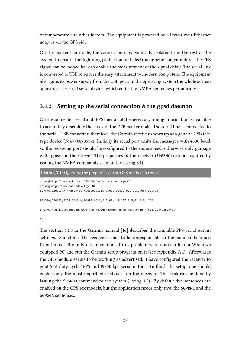
Aer the successful enumeration of the device (matching the type and speed of the de-vice), the daemon starts to collect the information from the receiver. e CC of the GPSis steered to the UTC, so the transmied timestrings are in UTC scale, thus the timedifference from the PTP timescale should be corrected.
If the proper configuration is found, it’s safe to start the gpsd in the background as adaemon, simply omit the -D and -N switches. To con Figure the daemon as a systemservice please refer to the documentation of your distribution. Aer the procedure, thegpsd is ready to transmit the collected information to the time sync utilities to disciplinethe clock of the network adapter.
3.1.3 Disciplining the time and frequency on network adapters
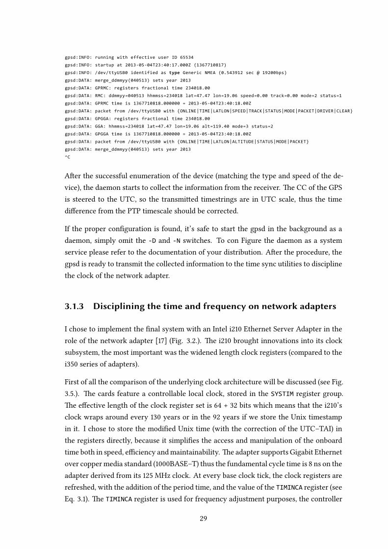
I chose to implement the final system with an Intel i Ethernet Server Adapter in therole of the network adapter [] (Fig. ..). e i brought innovations into its clocksubsystem, the most important was the widened length clock registers (compared to thei series of adapters).
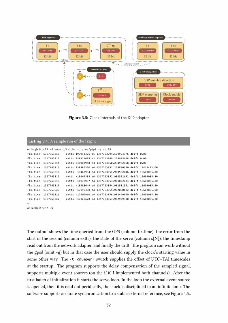
First of all the comparison of the underlying clock architecture will be discussed (see Fig...). e cards feature a controllable local clock, stored in the SYSTIM register group.e effective length of the clock register set is + bits which means that the i’sclock wraps around every years or in the years if we store the Unix timestampin it. I chose to store the modified Unix time (with the correction of the UTC–TAI) inthe registers directly, because it simplifies the access and manipulation of the onboardtime both in speed, efficiency andmaintainability. e adapter supports Gigabit Ethernetover copper media standard (BASE–T) thus the fundamental cycle time is ns on theadapter derived from its MHz clock. At every base clock tick, the clock registers arerefreshed, with the addition of the period time, and the value of the TIMINCA register (seeEq. .). e TIMINCA register is used for frequency adjustment purposes, the controller
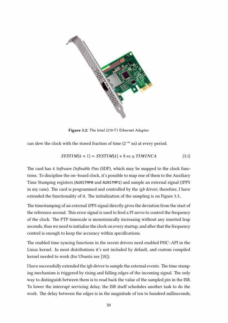
Figure 3.2: The Intel i210-T1 Ethernet Adapter
can slew the clock with the stored fraction of time (⁻³² ns) at every period.
𝑆𝑌𝑆𝑇𝐼𝑀[𝑘 + 1] = 𝑆𝑌𝑆𝑇𝐼𝑀[𝑘] + 8 𝑛𝑠 ± 𝑇𝐼𝑀𝐼𝑁𝐶𝐴 (.)
e card has Soware Definable Pins (SDP), which may be mapped to the clock func-tions. To discipline the on–board clock, it’s possible to map one of them to the AuxiliaryTime Stamping registers (AUXSTMP0 and AUXSTMP1) and sample an external signal (PPSin my case). e card is programmed and controlled by the igb driver; therefore, I haveextended the functionality of it. e initialization of the sampling is on Figure ...
e timestamping of an external PPS signal directly gives the deviation from the start ofthe reference second. is error signal is used to feed a PI servo to control the frequencyof the clock. e PTP timescale is monotonically increasing without any inserted leapseconds, thuswe need to initialize the clock on every startup, and aer that the frequencycontrol is enough to keep the accuracy within specifications.
e enabled time syncing functions in the recent drivers need enabled PHC–API in theLinux kernel. In most distributions it’s not included by default, and custom compiledkernel needed to work (for Ubuntu see []).
I have successfully extended the igb driver to sample the external events. e time stamp-ing mechanism is triggered by rising and falling edges of the incoming signal. e onlyway to distinguish between them is to read back the value of the sampled pin in the ISR.To lower the interrupt servicing delay, the ISR itself schedules another task to do thework. e delay between the edges is in the magnitude of ten to hundred milliseconds,

igb_enable() STOPSelect and
enable SDPnSet SDPn as input Enable interrupts
Figure 3.3: Initialization of pin sampling
extts_work() STOPRead
AUXSTMPRead SDPn Fire event
Rising edge?
No
Yes
Figure 3.4: Processing of the edges
and the whole process should not take more than few milliseconds. Both hardware canhold only one time stamp, but in most cases, the samples are processed fast enough thatit won’t be a problem. e processing of the time stamps is depicted byFigure .. ereadout of the timestaps is done through the raw read of the AUXSTMP registers. e sam-ple of the SDP pin is necessary to decide the direction of the sampled edge (rising/falling).e readout of the time stamps are necessary in every cases, because the AUXSTMP reg-isters are latched and won’t receive any new event stamp until they are read out. At theend the routine fires an event which can be polled by the user–space programs throughthe PHC–API.
e driver modifications are also applicable to the multi–port i family of networkadapters []. ere are few minor differences between the clock architecture of theadapters, such as the onboard clock of the i is just bits long. is limitation iscircumvented with the usage of the clock infrastructure in the kernel which supportsarbitrary long time handling with finite width counters. e time handling in the driverroutines in this case always includes a time conversion call may lower the accuracyby negligible amount. e multi–port i silicon contains or independent onboardclocks, which should be synchronized by the user in some applications (TC, BC).
I have developed an user–space utility called ts2phc, which is a modified version of thephc2sys utility included with the linuxptp. e soware feeds the absolute time intothe PHC’s clock at startup and the included servo controls the frequency of the clock.e absolute time is queried through the gpsd’s SHM driver. e driver of the adapterdoesn’t arm the interrupts of the card unless it has an active IP address; therefore, theutility needs an active, configured adapter, otherwise the soware does not function.e console output of the soware is shown in listing ..
+
+
8 ns
Refresh
Clock registers
Periodic activity
Auxiliary stamp registers
Control registers
Latches on event
CTRL CTRL_EXT
SDP enable / direction
TSSDP
SDP mapping
TSAUXC
Clock enableTIMINCA
2-32 ns
31 bits + sign
AUXSTMPH0 AUXSTMPL0
1 ns
32 bit
Carry Carry
1 s
32 bit
SYSTIMR
2-32 ns
32 bit
SYSTIML
1 ns
32 bit
SYSTIMH
1 s
32 bit
Figure 3.5: Clock internals of the i210 adapter
Listing 3.4: A sample run of the ts2phc
onlab@mitpc37:~$ sudo ./ts2phc -d /dev/ptp0 -g -t 35
fix.time: 1367763813 extts 199993376 s1 1367763794.199993376 drift 0.00
fix.time: 1367763813 extts 238925608 s2 1367763849.238925608 drift 0.00
fix.time: 1367763814 extts 238902968 s3 1367763850.238902968 drift 0.00
fix.time: 1367763815 extts 238880320 s4 1367763851.238880320 drift 19443472.00
fix.time: 1367763816 extts -19467954 s4 1367763851.980532046 drift 13603085.80
fix.time: 1367763817 extts -19467308 s4 1367763852.980532692 drift 13603085.80
fix.time: 1367763818 extts -18977997 s4 1367763853.981022003 drift 13603085.80
fix.time: 1367763819 extts -18488649 s4 1367763854.981511351 drift 13603085.80
fix.time: 1367763820 extts -17999308 s4 1367763855.982000692 drift 13603085.80
fix.time: 1367763821 extts -17509960 s4 1367763856.982490040 drift 13603085.80
fix.time: 1367763822 extts -17020620 s4 1367763857.982979380 drift 13603085.80
^C
onlab@mitpc37:~$
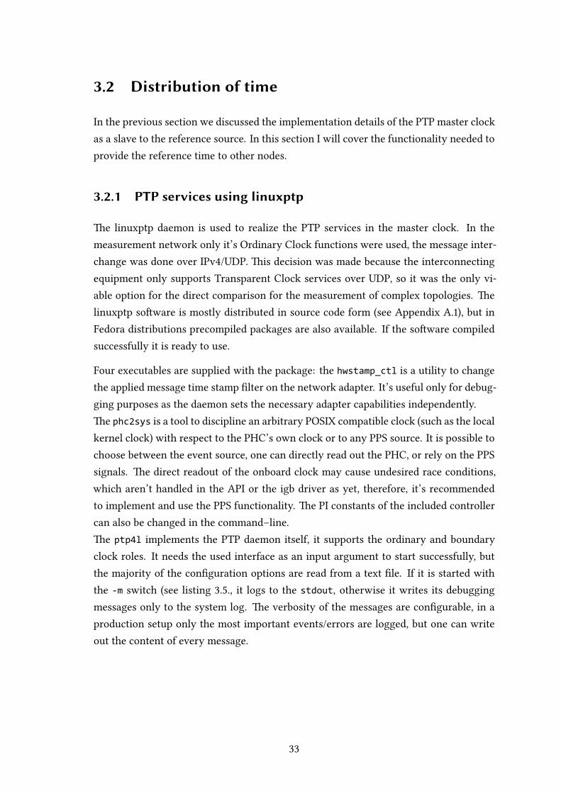
e output shows the time queried from the GPS (column fix.time), the error from thestart of the second (column exs), the state of the servo (column s[N]), the timestampread out from the network adapter, and finally the dri. e program can work withoutthe gpsd (omit -g) but in that case the user should supply the clock’s starting value insome other way. e -t <number> switch supplies the offset of UTC–TAI timescalesat the startup. e program supports the delay compensation of the sampled signal,supports multiple event sources (on the i I implemented both channels). Aer thefirst batch of initialization it starts the servo loop. In the loop the external event sourceis opened, then it is read out peridically, the clock is disciplined in an infinite loop. esoware supports accurate synchronization to a stable external reference, see Figure ...
3.2 Distribution of time
In the previous section we discussed the implementation details of the PTP master clockas a slave to the reference source. In this section I will cover the functionality needed toprovide the reference time to other nodes.
3.2.1 PTP services using linuxptp
e linuxptp daemon is used to realize the PTP services in the master clock. In themeasurement network only it’s Ordinary Clock functions were used, the message inter-change was done over IPv/UDP. is decision was made because the interconnectingequipment only supports Transparent Clock services over UDP, so it was the only vi-able option for the direct comparison for the measurement of complex topologies. elinuxptp soware is mostly distributed in source code form (see Appendix A.), but inFedora distributions precompiled packages are also available. If the soware compiledsuccessfully it is ready to use.
Four executables are supplied with the package: the hwstamp_ctl is a utility to changethe applied message time stamp filter on the network adapter. It’s useful only for debug-ging purposes as the daemon sets the necessary adapter capabilities independently.e phc2sys is a tool to discipline an arbitrary POSIX compatible clock (such as the localkernel clock) with respect to the PHC’s own clock or to any PPS source. It is possible tochoose between the event source, one can directly read out the PHC, or rely on the PPSsignals. e direct readout of the onboard clock may cause undesired race conditions,which aren’t handled in the API or the igb driver as yet, therefore, it’s recommendedto implement and use the PPS functionality. e PI constants of the included controllercan also be changed in the command–line.e ptp4l implements the PTP daemon itself, it supports the ordinary and boundaryclock roles. It needs the used interface as an input argument to start successfully, butthe majority of the configuration options are read from a text file. If it is started withthe -m switch (see listing .., it logs to the stdout, otherwise it writes its debuggingmessages only to the system log. e verbosity of the messages are configurable, in aproduction setup only the most important events/errors are logged, but one can writeout the content of every message.

Listing 3.5: A sample run of the ptp4l (slave state)
onlab@mitpc37:~$ sudo ./ptp4l -f default.cfg -i eth7 -p /dev/ptp0 -m
ptp4l[162683.928]: selected /dev/ptp0 as PTP clock
ptp4l[162683.929]: failed to read out the clock frequency adjustment: Operation
not supported
ptp4l[162683.929]: port 1: get_ts_info not supported
ptp4l[162683.930]: driver changed our HWTSTAMP options
ptp4l[162683.931]: tx_type 1 not 1
ptp4l[162683.931]: rx_filter 1 not 12
ptp4l[162683.931]: port 1: INITIALIZING to LISTENING on INITIALIZE
ptp4l[162683.931]: port 0: INITIALIZING to LISTENING on INITIALIZE
ptp4l[162684.748]: port 1: new foreign master 0050c2.fffe.d28dfc-1
ptp4l[162688.898]: selected best master clock 0050c2.fffe.d28dfc
ptp4l[162688.898]: port 1: LISTENING to UNCALIBRATED on RS_SLAVE
ptp4l[162689.988]: port 1: minimum delay request interval 2^3
ptp4l[162691.037]: master offset -636 s0 adj +0 path delay 1686
ptp4l[162692.038]: master offset -679 s1 adj -43 path delay 1686
ptp4l[162693.188]: master offset -30508 s2 adj -30551 path delay 1686
ptp4l[162693.188]: port 1: UNCALIBRATED to SLAVE on MASTER_CLOCK_SELECTED
ptp4l[162694.198]: master offset -22593 s2 adj -31788 path delay 1686
ptp4l[162695.198]: master offset -13494 s2 adj -29467 path delay 1686
ptp4l[162696.339]: master offset -5718 s2 adj -25739 path delay 1686
ptp4l[162697.348]: master offset -2611 s2 adj -24348 path delay 1686
ptp4l[162698.348]: master offset -990 s2 adj -23510 path delay 1686
ptp4l[162699.439]: master offset -62 s2 adj -22879 path delay 1686
ptp4l[162700.458]: master offset 95 s2 adj -22741 path delay 1686
ptp4l[162701.458]: master offset 164 s2 adj -22643 path delay 1686
ptp4l[162702.548]: master offset 163 s2 adj -22595 path delay 1686
ptp4l[162703.569]: master offset 93 s2 adj -22616 path delay 1686
ptp4l[162704.568]: master offset -18 s2 adj -22699 path delay 1686
ptp4l[162705.719]: master offset 20 s2 adj -22667 path delay 1686
ptp4l[162706.738]: master offset 47 s2 adj -22634 path delay 1686
ptp4l[162707.739]: master offset 10 s2 adj -22657 path delay 1686
ptp4l[162708.889]: master offset -46 s2 adj -22710 path delay 1686
ptp4l[162709.899]: master offset -47 s2 adj -22724 path delay 1686
ptp4l[162710.899]: master offset 45 s2 adj -22646 path delay 1686
ptp4l[162712.049]: master offset 7 s2 adj -22671 path delay 1686
ptp4l[162713.069]: master offset -27 s2 adj -22703 path delay 1686
ptp4l[162714.069]: master offset -12 s2 adj -22696 path delay 1686
ptp4l[162715.219]: master offset 22 s2 adj -22666 path delay 1686
ptp4l[162716.229]: master offset 60 s2 adj -22621 path delay 1686
ptp4l[162717.229]: master offset -32 s2 adj -22695 path delay 1686
^Cptp4l[162717.953]: caught signal 2
ptp4l[162717.953]: caught signal 2
onlab@mitpc37:~$
e user can con Figure the BMC fields in the configuration file has the most impor-tant fields, such as clockClass, clockAccuracy. When the internal clock is adjustedto the external GPS, the clock class is set to which denotes frequency traceable timesource. If the GPS reception is unavailable it should be set to but the automatic seingis currently unimplemented. e clock’s accuracy is set the , which means that theclock provides the time with µs accuracy (worst case estimate). I haven’t measuredthe Allan deviation of the clock so I le the default offsetScaledLogVariance value in
igb_enable()TRGTTIM
initializationSTOP
Select and enable SDPn
Set SDPn as output
TRGTTIM enable
Enable interrupts
Figure 3.6: The initialization of the 1PPS output
the seings. e field free_running in a configuration file is used in certain measure-ments for example to measue the asymmetries in the network. emeasured asymmetryaerwards can be mitigated in the servo with the usage of the delayAsymmetry field.
e linuxptp daemon is configurable run–time to some extent, and we can control thedaemon’s operation and it’s datasets with the provided pmc tool. I have not looked intothe depths of the tool, but it’s usage is inevitable to make the failover (e.g. end of GPSreception) automatic.
3.2.2 Supporting legacy equipment
e support of non–PTP capable equipment is inevitable to make the system usable inpractice. e clock information is should be distributed in at least two different ways:
. e absolute clock information over a parallel/serial protocol,
. the phase and frequency information via one–wire connection.
e absolute timing may implemented in an absolutely soware defined solution, forexample a program can read the PHC repeatedly and copy the value of it to the serial port.e phase information shall be generated by the network adapter to ensure maximalaccuracy of the system. e i adapter supports the generation of PPS signals in acompletely autonomous way (only for % duty cycle).
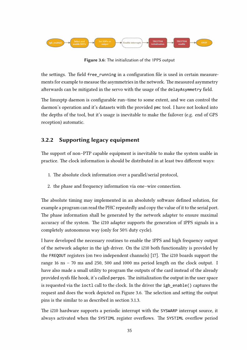
I have developed the necessary routines to enable the PPS and high frequency outputof the network adapter in the igb driver. On the i both functionality is provided bythe FREQOUT registers (on two independent channels) []. e i boards support therange ns – ms and , and ms period length on the clock output. Ihave also made a small utility to program the outputs of the card instead of the alreadyprovided sysfs file hook, it’s called perpps. e initialization the output in the user spaceis requested via the ioctl call to the clock. In the driver the igb_enable() captures therequest and does the work depicted on Figure .. e selection and seing the outputpins is the similar to as described in section ...
e i hardware supports a periodic interrupt with the SYSWARP interrupt source, italways activated when the SYSTIML register overflows. e SYSTIML overflow period
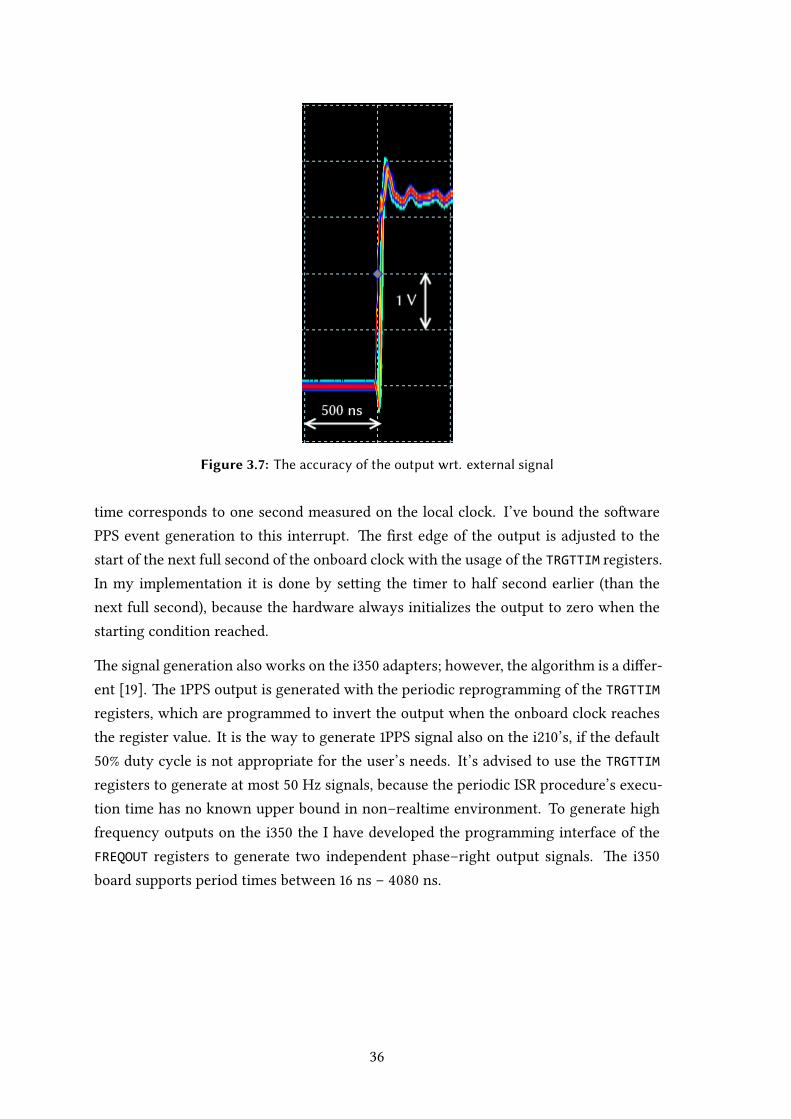
Figure 3.7: The accuracy of the output wrt. external signal
time corresponds to one second measured on the local clock. I’ve bound the sowarePPS event generation to this interrupt. e first edge of the output is adjusted to thestart of the next full second of the onboard clock with the usage of the TRGTTIM registers.In my implementation it is done by seing the timer to half second earlier (than thenext full second), because the hardware always initializes the output to zero when thestarting condition reached.
e signal generation also works on the i adapters; however, the algorithm is a differ-ent []. e PPS output is generated with the periodic reprogramming of the TRGTTIMregisters, which are programmed to invert the output when the onboard clock reachesthe register value. It is the way to generate PPS signal also on the i’s, if the default% duty cycle is not appropriate for the user’s needs. It’s advised to use the TRGTTIM
registers to generate at most Hz signals, because the periodic ISR procedure’s execu-tion time has no known upper bound in non–realtime environment. To generate highfrequency outputs on the i the I have developed the programming interface of theFREQOUT registers to generate two independent phase–right output signals. e iboard supports period times between ns – ns.

4 | Measurements and validation
e accuracy of the synchronization system can only specified aer series of measure-ments. Aer the introduction of the test equipment and the initial calibration steps, thetest methods will be introduced. is chapter concludes in a detailed explanation of themeasurement records.
4.1 Testing equipment & configuration
4.1.1 Reference clock for calibration & validation
In my test setup a Meinberg LANTIMEM GPS PTPv reference clock (Fig. ..) wereused to validate the master clock’s accuracy. It can synchronize itself to GPS, PTP orNTP time sources and it can propagate the timing informations over NTP and PTP pro-tocols (see []) or via legacy outputs. e equipment has serial, PPS, Pulse Per Minute, MHz, Time Code and an arbitrary frequency synthesizer output which covers almostevery functionality needed by legacy equipments. In the following measurements the in-tegrated OCXO based clock was disciplined by the GPS receiver. e crystal’s insulationfrom the ambient temperature (hence the name oven controlled) improves the internalclock’s holdover capabilities, when the GPS reception is unavailable. e GPS receiverof the equipment uses downmixing in its antenna; therefore, the downmixed GPS signalcan be transmied over cheap (RG–) coaxial cabling. e reference clock can be man-aged through a dedicated network interface and its PTP functions are served through aseparate Ethernet port and has a user–friendly web interface for configuration.
Figure 4.1: Meinberg M600 GPS/PTP reference clock
4.1.2 Nodes for testing and remote development
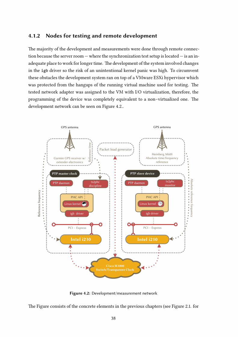
e majority of the development and measurements were done through remote connec-tion because the server room—where the synchronization test setup is located— is an in-adequate place to work for longer time. e development of the system involved changesin the igb driver so the risk of an unintentional kernel panic was high. To circumventthese obstacles the development system ran on top of a VMware ESXi hypervisor whichwas protected from the hangups of the running virtual machine used for testing. etested network adapter was assigned to the VM with I/O virtualization, therefore, theprogramming of the device was completely equivalent to a non–virtualized one. edevelopment network can be seen on Figure ...
Garmin GPS receiver w/ extender electronics
GPS antenna
Cisco IE3000Switch/Transparent Clock
PTP master clock
PCI – Express
PTP daemon
Intel i210
PHC API
igb driver
Linux kernel
ts2phc discipline
PTP slave device
PCI – Express
PTP daemon
Intel i210
PHC API
igb driver
Linux kernel
ts2phcmonitor
Ref
eren
ce fr
eque
ncy
Meinberg M600Absolute time/frequency
reference
GPS antenna
Packet load generator
Ref
eren
ce t
ime
Absolute reference frequency
Figure 4.2: Development/measurement network
e Figure consists of the concrete elements in the previous chapters (see Figure .. for

comparison). e packet load generator was a VM on the development system, the packetgenerator was the iperf tool. It’s a client/server soware which generates dummy pack-ets on the client and discards them on the server. I used the artifically generated networktraffic to demonstrate of the effects of the high network load on the system’s accuracy.e tests were conducted on Ubuntu Linux . with kernel version ..-ptp. is ker-nel is not part of the default distribution nor the common package repositories, therefore,a small walkthrough is included in Appendix⁇ to help the reader to reproduce the samemeasurement system.
4.1.3 Other active elements
For the multi–slave measurements the nodes were connected via a Cisco IE Indus-trial Ethernet switch. e switch supports the BASE–TX standard communicationon ports and BASE–T on ports and it can act as a PTP Transparent Clock or aPTP Boundary Clock over UDP. I did measurements with enabled and disabled transpar-ent clock modes to show the change of accuracy under heavy load. e basics of thetransparent clocks are described on page .
Figure 4.3: Cisco IE3000 (4 port version)
Initially, the output signals of the synchronization system were measured with a Pico-scope. e control and visualization soware of the device ran on the weasel virtual-ization host in a separate virtual machine. e scope’s digital phosphore mode wereused as an independent tool to visualize long–term effects. e instrument used in the

measurements has gigasample/s sampling speed on one channel or megasample/son two, and the bandwidth on of the inputs ( MHz) is high enough to correctly sam-ple the square wave signals. erefore, the instrument is suitable for the measurementspresented in this paper.
4.2 Measurement methodologies & results
4.2.1 Measurement methods
In the initial measurements I checked the synchronization quality of the signals withan oscilloscope to make sure that the soware reported offset values are valid. ismethod is useful because the visualization of the signals is made by an autonomousequipment. I also wanted to show the histograms of the measurements which is notsupported by the oscilloscope, so the absolute reference or the Garmin receiver’s signalwas fed into the i adapter. When the synchronization of the cards were done bythe linuxptp daemon, the adapter generated timestamps from the incoming signal withusage of the ts2phc utility. In this case the timestamps show the error with respectto the start every GPS second and they show the accuracy of the system compared to areference quality PPS signal. When the card was synchronized to the absolute referencePPS/serial time information, I was able to use it as a timestamp unit to measure anothersignal too (presented in section ..). With this measurement method I converted thedevice under test into a measurement device.
4.2.2 Calibration process
Calibration for the Tx/Rx asymmetry
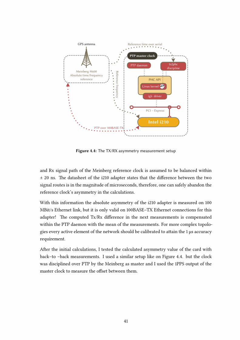
e PTP algorithm assumes that the link delay is symmetrical in the physical network.Unfortunately, in real–world scenarios the majority of the network adapters have differ-ent signal propagation times on their transmit and receive paths. ese kinds of asymme-tries are near to the magnitude of our desired accuracy goal; therefore, the measurementand compensation of them are inevitable.
eTx/Rx asymmetrymeasurement test setup is pictured on Figure .., the deviceswereconnected directly. e combination of the serial and PPS timing information was fedinto the ts2phc tool which disciplined the clock of the PTPmaster node and the linuxptpdaemon ran in simulation mode (without any clock correction applied). e output ofthe linuxptp was processed and presented on Figure .. For the measurements the Tx
PTP master clock
PCI – Express
PTP daemon
Intel i210
PHC API
igb driver
Linux kernel
ts2phc discipline
Meinberg M600Absolute time/frequency
reference
GPS antenna
Reference frequency
PTP over 100BASE-TX
Reference time over serial
Figure 4.4: The TX/RX asymmetry measurement setup
and Rx signal path of the Meinberg reference clock is assumed to be balanced within± ns. e datasheet of the i adapter states that the difference between the twosignal routes is in the magnitude of microseconds, therefore, one can safely abandon thereference clock’s asymmetry in the calculations.
With this information the absolute asymmetry of the i adapter is measured on MBit/s Ethernet link, but it is only valid on BASE–TX Ethernet connections for thisadapter! e computed Tx/Rx difference in the next measurements is compensatedwithin the PTP daemon with the mean of the measurements. For more complex topolo-gies every active element of the network should be calibrated to aain the µs accuracyrequirement.
Aer the initial calculations, I tested the calculated asymmetry value of the card withback–to –back measurements. I used a similar setup like on Figure .. but the clockwas disciplined over PTP by the Meinberg as master and I used the PPS output of themaster clock to measure the offset between them.

0 1 2 3 4 5 6 7 8 9 10420
440
460
480
500
520
540
Time of measurement [h]
Off
set
fro
m P
TP
mast
er
[ns]
µ = 482.71 ns, σ = 23.69 ns
Figure 4.5: The TX/RX asymmetry (extracted from ptp4l output)
Figure 4.6: The offset from the absolute reference with 1PPS disci-pline on the i210 master measured with Picoscope with ap-plied correction

0 1 2 3 4 5 6 7-80
-60
-40
-20
0
20
40
60
80
Time of measurement [h]
Off
set
fro
m m
ast
er
[ns]
-80 -60 -40 -20 0 20 40 60 800
200
400
600
800
1000
1200
Offset from master [ns]
Nu
mb
er o
f o
ccu
ren
ce
Σ: ~25000 samples
Figure 4.7: The offset of the slave from the master aer applying thecorrection (time series & histogram)
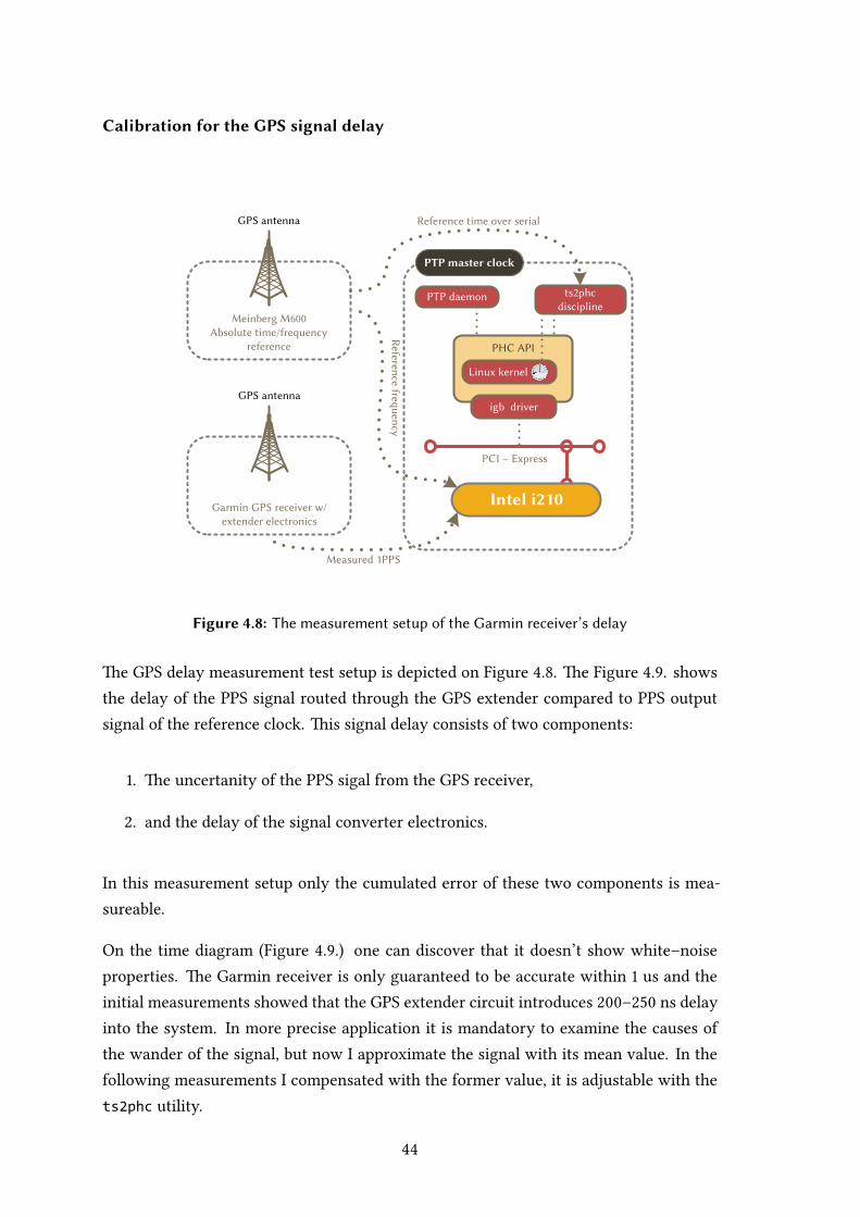
Calibration for the GPS signal delay
PTP master clock
PCI – Express
PTP daemon
Intel i210
PHC API
igb driver
Linux kernel
ts2phc discipline
Meinberg M600Absolute time/frequency
reference
GPS antenna
Reference frequency
Reference time over serial
Garmin GPS receiver w/extender electronics
GPS antenna
Measured 1PPS
Figure 4.8: The measurement setup of the Garmin receiver’s delay
e GPS delay measurement test setup is depicted on Figure .. e Figure .. showsthe delay of the PPS signal routed through the GPS extender compared to PPS outputsignal of the reference clock. is signal delay consists of two components:
. e uncertanity of the PPS sigal from the GPS receiver,
. and the delay of the signal converter electronics.
In this measurement setup only the cumulated error of these two components is mea-sureable.
On the time diagram (Figure ..) one can discover that it doesn’t show white–noiseproperties. e Garmin receiver is only guaranteed to be accurate within us and theinitial measurements showed that the GPS extender circuit introduces – ns delayinto the system. In more precise application it is mandatory to examine the causes ofthe wander of the signal, but now I approximate the signal with its mean value. In thefollowing measurements I compensated with the former value, it is adjustable with thets2phc utility.
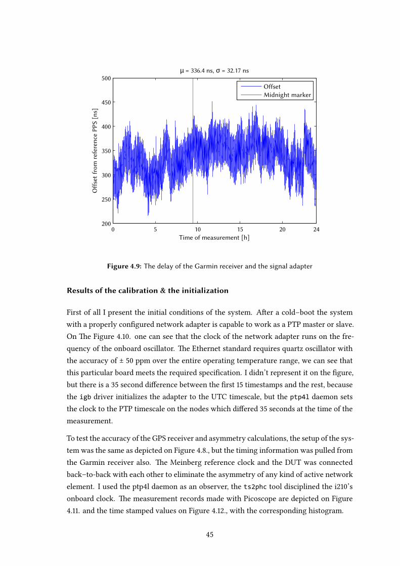
0 5 10 15 20 24200
250
300
350
400
450
500
Time of measurement [h]
Off
set
fro
m r
efer
ence
PP
S [
ns]
µ = 336.4 ns, σ = 32.17 ns
Offset
Midnight marker
Figure 4.9: The delay of the Garmin receiver and the signal adapter
Results of the calibration & the initialization
First of all I present the initial conditions of the system. Aer a cold–boot the systemwith a properly configured network adapter is capable to work as a PTP master or slave.On e Figure .. one can see that the clock of the network adapter runs on the fre-quency of the onboard oscillator. e Ethernet standard requires quartz oscillator withthe accuracy of ± ppm over the entire operating temperature range, we can see thatthis particular board meets the required specification. I didn’t represent it on the figure,but there is a second difference between the first timestamps and the rest, becausethe igb driver initializes the adapter to the UTC timescale, but the ptp4l daemon setsthe clock to the PTP timescale on the nodes which differed seconds at the time of themeasurement.
To test the accuracy of the GPS receiver and asymmetry calculations, the setup of the sys-tem was the same as depicted on Figure .., but the timing information was pulled fromthe Garmin receiver also. e Meinberg reference clock and the DUT was connectedback–to-back with each other to eliminate the asymmetry of any kind of active networkelement. I used the ptpl daemon as an observer, the ts2phc tool disciplined the i’sonboard clock. e measurement records made with Picoscope are depicted on Figure.. and the time stamped values on Figure .., with the corresponding histogram.

0 200 400 600 800 1000 1200 1400-4
-3.5
-3
-2.5
-2
-1.5
-1
-0.5
0x 10
7
Time of measurement [s]
Off
set
[ns]
Measurement points
Fitted line (-27 ppm)
Figure 4.10: The initial dri of the system
Figure 4.11: The offset from the absolute reference with direct con-nection to the i210 master measured with Picoscope

0 500 1000 1500 2000 2500 3000 3500-150
-100
-50
0
50
100
150
200
Time of measurement [s]
Off
set
fro
m r
efe
ren
ce t
ime [
ns]
µ = 16.38 ns, σ = 37.93 ns
-150 -100 -50 0 50 100 150 2000
50
100
150
200
250
Offset from reference time [ns]
Nu
mb
er o
f o
ccu
ren
ces
Σ: 3550 samples
Figure 4.12: The offset from the absolute reference with direct con-nection to the i210 master (time series & histogram)
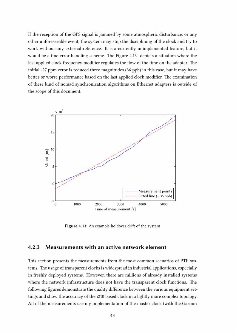
If the reception of the GPS signal is jammed by some atmospheric disturbance, or anyother unforeseeable event, the system may stop the disciplining of the clock and try towork without any external reference. It is a currently unimplemented feature, but itwould be a fine error handling scheme. e Figure .. depicts a situation where thelast applied clock frequency modifier regulates the flow of the time on the adapter. einitial - ppm error is reduced three magnitudes ( ppb) in this case, but it may havebeer or worse performance based on the last applied clock modifier. e examinationof these kind of nomad synchronization algorithms on Ethernet adapters is outside ofthe scope of this document.
0 1000 2000 3000 4000 5000-5
0
5
10
15
20x 10
4
Time of measurement [s]
Off
set
[ns]
Measurement points
Fitted line (~ 36 ppb)
Figure 4.13: An example holdover dri of the system
4.2.3 Measurements with an active network element
is section presents the measurements from the most common scenarios of PTP sys-tems. e usage of transparent clocks is widespread in industrial applications, especiallyin freshly deployed systems. However, there are millions of already installed systemswhere the network infrastructure does not have the transparent clock functions. efollowing figures demonstrate the quality difference between the various equipment set-tings and show the accuracy of the i based clock in a lightly more complex topology.All of the measurements use my implementation of the master clock (with the Garmin
GPS discipline) as themaster of the synchronization system, but on the slaves I measuredthe offset with respect to the Meinberg’s reference PPS signal.
e Figure .. shows the measurement records of a system where the switch does notsupport any kind of PTP functions but both of the nodes have hardware timestampingfunctionality. As one can see, the parameters of the offset are within the desired speci-fications stated in the thesis proposal. e maximal peak on the histogram with respectto the reference PPS signal implies that the clock of the slave system gains time. eremay be two causes of it, first the switch may introduce error in the delay computation,second the GPS signal of the custom receiver design is overcompensated. In some sys-tems this kind of acausality is forbidden, but it can be circumvented with a different GPSdelay value (e.g. the smallest value on Figure ..) When we replace the switch with atransparent clock (in reality I switched the TC mode on the switch), the measurementresults (Figure ..) show that the acausality is reduced, and the standard deviation de-creased, which was the expected behavior. In both cases I generated no traffic on theswitch to collect some baseline information about the synchronization system.
In the next two cases I used the traffic generator of the measurement system. I usedthe iperf utility to generate artifical traffic on the equipment. In previous papers [] Ipresented the effect of the client/server roles on the synchronization accuracy, therefore,I used the setup where the most obvious performance hit occurs. On the PTP slave clockI ran the iperf in the master role (traffic discarder – heavy load on the Rx traffic), and thetraffic generator was always the client (traffic generator). e master clock did not takepart of the traffic generation. I used TCP traffic in the tests because it automatically usesall of the safely available bandwith. e heavy load on receive side traffic (observed fromthe slave) means that in the switch the sync and delay response packets of the masterare queued stochastically.
e uneven reception of the sync and delay response packets highly degrades the trafficas we can observe on Figure .. e PI servo of the ptpl cannot lock onto the intervalscalculated from the message transmission/reception, because the path delay estimationis periodically fluctuates. If the residence time of the packets in the switch is measured(and wrien out into the packets of course), the non–deterministic jier of the sync& delay response packet is dropped from the equation, therefore it provides a higherquality estimator of the offsets and delays. e Figure .. depicts the effects of theresidence time correction on the accuracy. e mean and standard deviance of the errorsignal equals to the scenarios without any generated traffic. e wander of the signalis the effect of the daily wander of the Garmin receiver’s PPS output, compared to thechosen absolute reference (Fig. ..).

0 500 1000 1500 2000 2500 3000 3500-300
-250
-200
-150
-100
-50
0
50
100
150
Time of measurement [s]
Off
set
fro
m r
efe
ren
ce t
ime [
ns]
µ = -76.93 ns, σ = 59.36 ns
-300 -250 -200 -150 -100 -50 0 50 100 1500
50
100
150
200
250
Offset from reference time [ns]
Nu
mb
er o
f o
ccu
ren
ces
Σ: 3600 samples
Figure 4.14: The offset from the absolute reference with a switchwithout load (time series & histogram)

0 1000 2000 3000 4000 5000 6000 7000-200
-150
-100
-50
0
50
100
150
200
Time of measurement [s]
Off
set
fro
m r
efe
ren
ce t
ime [
ns]
µ = 1.814 ns, σ = 42.05 ns
-200 -150 -100 -50 0 50 100 150 2000
50
100
150
200
250
300
350
400
450
500
Offset from reference time [ns]
Nu
mb
er o
f o
ccu
ren
ces
Σ: 7150 samples
Figure 4.15: The offset from the absolute reference with a transpar-ent clock without load (time series & histogram)

0 500 1000 1500 2000 2500 3000-2
-1.5
-1
-0.5
0
0.5
1
1.5
2
2.5x 10
7
Time of measurement [s]
Off
set
fro
m r
efe
ren
ce t
ime [
ns]
-2 -1.5 -1 -0.5 0 0.5 1 1.5 2 2.5
x 107
0
50
100
150
200
250
Offset from reference time [ns]
Nu
mb
er o
f o
ccu
ren
ces
Σ: 2736 samples
Figure 4.16: The offset from the absolute referencewith a switchwithload (time series & histogram)
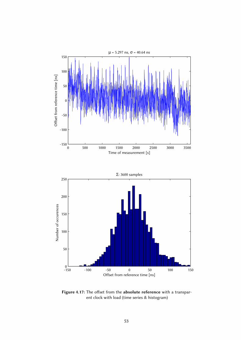
0 500 1000 1500 2000 2500 3000 3500-150
-100
-50
0
50
100
150
Time of measurement [s]
Off
set
fro
m r
efe
ren
ce t
ime [
ns]
µ = 5.297 ns, σ = 40.64 ns
-150 -100 -50 0 50 100 1500
50
100
150
200
250
Offset from reference time [ns]
Nu
mb
er o
f o
ccu
ren
ces
Σ: 3600 samples
Figure 4.17: The offset from the absolute reference with a transpar-ent clock with load (time series & histogram)

5 | Industrial applications and futuredirections
Sub–microsecond level of accuracy in timing is required inmany fields of distributed sys-tems. I’ve collected some interesting areas where the good quality time–base is manda-tory for the system’s proper functionality. In the descriptions of them I also emphasisethe related research ways of the presented system.
5.1 Common applications of packet based time syn-chronization
5.1.1 Usage in distributed measurement systems
To ensure the reconstruction of the order of the measurements in a distributed system,the local clock of the measurement nodes have to closely follow the flow of an arbitraryreference time. In non–wireless applications the distribution of the local clock mostlydone on the shared communication media. Most of the distributed measurement stan-dards require the implementation of a subset of the IEEE : protocol to aain therequired accuracy.
One example of the high–accuracy distributed measurements is the synchrophasor re-construction in power substation automation applications []. e measured current– voltage pairs are time stamped in the sensors and sent to the data processing nodes.e IEEE C..- Standard for Synchrophasor Measurements for Power Systems statesthe following: “A phase error of . degrees (. radian) will by itself cause % TotalVector Error (TVE) … is corresponds to a time error of ± μs for a Hz systemand ± μs for a Hz system”. It also states that “A time source that reliably providestime, frequency, and frequency stability at least times beer than these values corre-sponding to % TVE is highly recommended.”. e required accuracy of the timestampsare . μs in Hz and . μs in Hz systems. Without proper synchronization, the

measured data will be reconstructed in a false order, which makes the evaluation of theevents impossible. e sub–μs accuracy helps the operators to make faster and beerdecisions, compared to the older methods; the possibility to collect tens to thousaundsof sampling points per second provides superior feedback to the controlling personnel.
ere are commercially available products, which provide the time–base in these appli-cations, but the system presented in this paper is also capable act as grandmaster in thesesystems. ere are few issues unimplemented right now (such as SNMP capabilites), andthere are several requirements which are untested in the current configuration (Peer toPeer TC, VLAN tagging). Some of the unresolved issues are in the scope of further work.
5.1.2 Audio-video bridging
Nowadays the majority of the home entertainment systems use digital interconnections(DVI, S/PDIF, HDMI) to connect the sources (CD, DVD, BluRay players) to the endpoints(TV, Amplifier). By the usage of these interconnections, the integration capability of thedevices into home automation systems are poor. In professional A/V systems the usageof the master clock or genlock signals is common, but maintaining the synchronizedstate of the system is an enormous effort in the ever–changing connection standards. eusage of the ubiquitous Ethernet as the communication medium helps the integration,but poses problems to maintain the quality of service (lack of A/V sync, dropouts). eindustry proposed the . AVB standard family to resolve these problems. e IEEE
.AS Timing and Synchronization for Time-Sensitive Applications in Bridged Local Area
Networks standard defines a subprofile of the PTP standard covered in this document.e standard set also proposes methods to solve the traffic shaping, stream integrity andbandwidth reservation problems, but it’s not in the scope of this document [].
e main goal in the converged audio–visual systems to provide several streams simul-teanously, coexisting with the other traffic on the communication medium. With theusage of time synchronization the participating nodes can recover the reference clockfrom an arbitrary stream. Every node in the AVB domain synchronizes its clock to theelected grandmaster, and the stream source time stamps the data with respect its in-ternal clock. e playing end–nodes regenerates the media clock with the help of theaached time stamps and its synchronized onboard clock. e accuracy requirementsof an AV stream is in the order of milliseconds (lip–syncing); however, maintaining themedia clock requires sub–μs accuracy synchronization to implement a good quality dis-tributed PLL.
e presented system introduces some solutions to adapt AVB services, for example dis-ciplining a DAC clock, but it’s not a fully–fledged solution. e AVB soware stack is

not covered in this thesis, but there is at least one freely usable AVB framework underdevelopment []. e implementation of distributed PLL is also available with the pre-sented system, the slave PTP nodes can emit arbitrary frequency output signals derivedfrom the master’s PPS input.
5.1.3 Financial systems
In the financial sector the precise and accurate the timing of events is invaluable bothfor the trading parties and the controlling bodies of the market. e accurately timestamped data of transactions serves as proof of legibility and as an input for data–miningalgorithms to determine the optimal trading strategy. e trading soware gain theirnotion of time inmost likely from the Linux kernel; therefore a low–latency access to theaccurate time is a must–have. e accurate time base also needed for the measurementof network delays, which is a tool to optimize and reduce the time required to access thefinancial information.
e majority of these system are running on a virtualization platform. e distributionof the accurate time into the VMs is a challenging problem, which requires further inves-tigation. e technologies like I/O virtualization (IOMMU) or sharing a single resourcebetween multiple VM instances (SR–IOV ) — like the timing resources of an adapter — isan interesting problem to discover.
In the presented system, the phc2sys tool is capable to discipline the kernel clock to thePHC, but currently independent measurement methods are unavailable in my environ-ment (e.g. a CPU tracer); therefore the sub–μs accuracy is not proved with respect tothe kernel timer. e modern Ethernet adapters support some sort of DMAmapped intothe CPU cache address space (DCA), which may be the core of serving accurate time tothe legacy applications. ere are commercial solutions which are capable to achievesub–μs accuracy in kernel–time synchronization [].
5.2 Further directions & conclusion
e current system has the a few unsolved issues, which are required for the adoptionin production environment. e automatic distribution of the change in the external ref-erence is unavailable, the interoperation between various vendors is currently untested.e serial output of the system is unimplemented yet, and the I/O ports to external equip-ment should be upgraded to make it usable in production systems. With the usage ofcoaxial terminals, the EMC of the final product will be greatly improved.
e initial measurements showed that this concept can be used in the majority of mea-surement, financial and entertainment systems, as it’s cheap, reliable and accurate so-lution for the distribution of timing information. e underlying soware architecturehas an active development community, and most of the additional components are ver-satile enough to use it in a alternatively configured system. e accuracy of the syn-chronization in the hardware is proved with independent reference equipment, but themeasurement of the soware side is in the scope of further analysis.


Acknowledgement
First of all I would like to thank the help of my supervisors, Tamás Kovácsházy and ZoltánFodor. ey introduced me to the field of engineering in practice and provided me thenecessary knowledge and equipment since to carry on the writing of this thesis.
On the second I want to thank the support of my family, especially of my parents’, andmy late grandmother’s support throughout the years of studying, and the help of mybrother Barnabás who helped me correct the language used in this document.
ird I want to thank everything to the people of the Schönherz Kollégium. During mysix years long stay there, I have learned invaluable lessons about working with otherpeople on projects having tangible value, and the importance of self–management ineveryday life.

Köszönetnyilvánítás
Elsősorban szeretném megköszönni a Kovácsházy Tamásnak és Fodor Zoltánnak konzu-lensi segítségét, akikkel már óta dolgozom ezen területen, és rengeteg hasznos tu-dást adtak át a mérnöki hivatás elméleti és gyakorlati oldalával kapcsolatban. Különköszönet Zolinak az eszközökért, segítségükkel az általam felépíte rendszer ipari kör-nyezetben is megállhatja a helyét!
Másodsorban szeretném megköszönni a családom segítségét, különös tekinteel Édes-anyámra és Édesapámra, akik biztosítoák a számomra az a környezetet, hogy nekemcsak a számomra kedves és hasznos dolgaimra koncentrálhassak. Ezen felül köszönöma nyelvi támogatást öcsémnek Barnabásnak, segítségének hála a dolgozat angol nyelve-zete remélhetőleg az olvasó számára is érthető lesz.
Pro tertio egzakt nevesítés nélkül szeretnékmegköszönni mindent a Schönherz Kollégiumközösségének, úgy vélem, az elmúlt évben sikerült a szakmán felül mindazt a tudástelsajátítanom, ami lehetővé teszi azt, hogy mérnökként megtaláljam a helyemet a világ-ban.
Végezetül szeretnék megemlékezni mindazokról, akik már nem élheék meg eme műelkészültét, de minden erejükkel azon voltak, hogy megvalósíthassam azt.
List of Figures
1.1 The offset correction algorithm . . . . . . . . . . . . . . . . . . . . . . . . 10
1.2 The delay estimation algorithm . . . . . . . . . . . . . . . . . . . . . . . . 11
1.3 Block diagram of a boundary clock . . . . . . . . . . . . . . . . . . . . . . 12
1.4 Block diagram of a transparent clock . . . . . . . . . . . . . . . . . . . . . 13
1.5 The Space Segment of the GPS [11] . . . . . . . . . . . . . . . . . . . . . . 15
2.1 The proposed design of the synchronization system . . . . . . . . . . . . . 18
2.2 Alternatives to acquire message timestamps [15] . . . . . . . . . . . . . . 19
2.3 The layout of the PHC API [2] . . . . . . . . . . . . . . . . . . . . . . . . . 21
3.1 Schematic of the GPS extender circuit . . . . . . . . . . . . . . . . . . . . 26
3.2 The Intel i210-T1 Ethernet Adapter . . . . . . . . . . . . . . . . . . . . . . 30
3.3 Initialization of pin sampling . . . . . . . . . . . . . . . . . . . . . . . . . . 31
3.4 Processing of the edges . . . . . . . . . . . . . . . . . . . . . . . . . . . . . 31
3.5 Clock internals of the i210 adapter . . . . . . . . . . . . . . . . . . . . . . 32
3.6 The initialization of the 1PPS output . . . . . . . . . . . . . . . . . . . . . 35
3.7 The accuracy of the output wrt. external signal . . . . . . . . . . . . . . . 36
4.1 Meinberg M600 GPS/PTP reference clock . . . . . . . . . . . . . . . . . . . 37
4.2 Development/measurement network . . . . . . . . . . . . . . . . . . . . . 38
4.3 Cisco IE3000 (4 port version) . . . . . . . . . . . . . . . . . . . . . . . . . . 39
4.4 The TX/RX asymmetry measurement setup . . . . . . . . . . . . . . . . . . 41
4.5 The TX/RX asymmetry (extracted from ptp4l output) . . . . . . . . . . . . 42
4.6 The offset from the absolute reference with 1PPS discipline on the i210
master measured with Picoscope with applied correction . . . . . . . . . . 42
4.7 The offset of the slave from the master aer applying the correction (time
series & histogram) . . . . . . . . . . . . . . . . . . . . . . . . . . . . . . . 43
4.8 The measurement setup of the Garmin receiver’s delay . . . . . . . . . . . 44
4.9 The delay of the Garmin receiver and the signal adapter . . . . . . . . . . 45
4.10 The initial dri of the system . . . . . . . . . . . . . . . . . . . . . . . . . 46
4.11 The offset from the absolute referencewith direct connection to the i210master measured with Picoscope . . . . . . . . . . . . . . . . . . . . . . . 46
4.12 The offset from the absolute referencewith direct connection to the i210master (time series & histogram) . . . . . . . . . . . . . . . . . . . . . . . 47
4.13 An example holdover dri of the system . . . . . . . . . . . . . . . . . . . 48
4.14 The offset from the absolute reference with a switch without load (time
series & histogram) . . . . . . . . . . . . . . . . . . . . . . . . . . . . . . . 50
4.15 The offset from the absolute referencewith a transparent clock without
load (time series & histogram) . . . . . . . . . . . . . . . . . . . . . . . . . 51
4.16 The offset from the absolute reference with a switch with load (time
series & histogram) . . . . . . . . . . . . . . . . . . . . . . . . . . . . . . . 52
4.17 The offset from the absolute reference with a transparent clock with
load (time series & histogram) . . . . . . . . . . . . . . . . . . . . . . . . . 53
II

References
[1] G. Neville-Neil, “PTPd webpage.” http://ptpd.sf.net/ (Mar. 2013).
[2] R. Cochran and C. Marinescu, “Design and implementation of a PTP clock in-
frastructure for the Linux kernel,” in Precision Clock Synchronization for Measure-
ment Control and Communication (ISPCS), 2010 International IEEE Symposium on,
pp. 116–121, 2010.
[3] R. Cochran, “The Linux PTP Project Homepage.” http://linuxptp.sf.net/ (Apr.
2013).
[4] U.S. Navy, “Systems of Time.” http://www.usno.navy.mil/USNO/time/
master-clock/systems-of-time (Apr. 2013).
[5] T. C. on Sensor Technology (TC-9), IEEE Standard for a Precision Clock Synchroniza-
tion Protocol for Networked Measurement and Control Systems. IEEE Instrumenta-
tion and Measurement Society, 2008.
[6] G. M. Garner, “Description of Use of IEEE 1588 Followup Peer-to-Peer Transparent
Clock in A/V Bridging Networks,” tech. rep., Samsung, 2006.
[7] J. Corbet, A. Rubini, and G. Kroah-Hartman, Linux Device Drivers, Third Edition,
ch. Time, Delays, and Deferred Work, pp. 183 – 212. O’Reilly, 2005. available at:
http://www.iitg.ernet.in/asahu/cs421/books/LDD3e.pdf.
[8] man-pages project, “Time (7) man pages.” Available at: man -s 7 time.
[9] Google Official Blog, “Time, technology and leaping seconds.” http://googleblog.
blogspot.hu/2011/09/time-technology-and-leaping-seconds.html (May
2013).
[10] G. Blewi, Geodetic Applications of GPS, ch. Basics of the GPS Technique: Obser-
vation Equations, pp. 9–55. Swedish Land Survey, 1997.
[11] GCAPTAIN STAFF, “SARSAT Satellite Tracking with Google Earth.” http://
gcaptain.com/find-satellites-google-earth/ (May 2013).
III
[12] D. Goodin, “How to bring down mission-critical GPS networks with
$2,500.” Available at: http://arstechnica.com/security/2012/12/
how-to-bring-down-mission-critical-gps-networks-with-2500/ (March
2012).
[13] ARINC Engineering Services, LLC, “Navstar GPS Space Segment/Navigation
User Interfaces,” Available at: http://www.losangeles.af.mil/shared/media/
document/AFD-070803-059.pdf (Jan. 2013).
[14] U.S. Navy, “USNONAVSTAR Global Positioning System Information.” http://www.
usno.navy.mil/USNO/time/gps/gps-info (May 2013).
[15] Intel, “Hardware-Assisted IEEE 1588 implementation in the Intel® IXP46X Product
Line,” white paper, 2005.
[16] Garmin International Inc., GPS 18x Technical Specifications, January 2008.
[17] LAN Access Division, Intel® Ethernet Controller i210 Datasheet. Intel Corp., 2.1 ed.,
November 2012.
[18] P. van der Does, “Compile the mainline Linux kernel for Ubuntu.” Available
at: http://blog.avirtualhome.com/compile-mainline-kernel-ubuntu/ (Jan.
2013), 2012.
[19] LAN Access Division, Intel® Ethernet Controller i350 Datasheet. Intel, 2.05 ed., De-
cember 2011.
[20] Meinberg,Manual of the LANTIMEM600 GPS PTPv2 Network Time Server and PTPv2
Grandmaster Clock.
[21] T. Kovácsházy and B. Ferencz, “Nagy pontosságú IEEE 1588 (PTP) óraszinkronizá-
ciós protokoll implementációk fejlesztése és alkalmazása.,” in Networkshop 2013,
Sopron, 2013.
[22] Symmetricom, “Profile for Use of IEEE 1588™ Precision Time Protocol in Power
System Applications.” Available at: http://www.symmetricom.com/media/files/
resources/webcasts/PTPPowerProfilePresentation_Webinar.pdf (May 2013).
[23] R. Boatright, “Understanding ieee’s new audio video bridging standards.”
Available at: http://www.embedded.com/design/connectivity/4008284/
Understanding-IEEE-s-new-audio-video-bridging-standards (Dec. 2012).
[24] Intel, “Open AVB webpage.” https://github.com/intel-ethernet/Open-AVB
(Apr 2013).
IV

[25] Symmetricom, “Delivering Sub-Microsecond Accurate Time to Linux Applications
Around the World.” Available at: http://www.symmetricom.com/media/files/
resources/webcasts/Webinar-Low-Latency-Dec-04-2012.pdf (May 2013).
V
Appendix
A.1 Obtaining the soware and source code
In this section I provide the availability all of the soware and source codes, which are
used in this paper.
A.1.1 igb–pps & utilites
The modified igb driver and the corresponding utilites are maintained by the author
(Bálint Ferencz, <[email protected]>). It’s hosted on the Atlassian Bitbucket
version control system. One can download it by issuing the following command:
git clone https://bitbucket.org/fernya/igb-pps.git igb-pps
The project is currently in embryonic state so I haven’t provided any tagged tarball for
distribution.
A.1.2 Linuxptp
The linuxptp soware is maintained by Richard Cochran, and it is hosted as a Source-
forge project [3]. Since the introduction of the version 1.0, the soware gets released in
tarball format. For those who are interested in the nightly commits, the (read–only) git
repository may be cloned with issuing the following command:
git clone git://git.code.sf.net/p/linuxptp/code linuxptp
A.1.3 Garmin setup utility
To configure the GPS receiver I have used the Windows based configuration tool. The
usage of the utility is straightforward, aer a successful connection, the properties of the
VI

receiver are editable in a dialog box. Aer saving, the new seings can be applied to the
receiver with serial uploading. Themajority of the seings are effective aer upload, but
for the measurement output one needs to repower the receiver. The program is available
from the following place:
http://www8.garmin.com/support/agree.jsp?id=4071
VII