Embed Size (px)
Citation preview

Operating Instructions
Hardness Tester EQUOTIP®
and EQUTIP®2

Copyright © 1978 by Proceq SA, Switzerland 820 350 01E ver 05 200610th edition
Standardized according to ASTM A 956-96.
Proceq SA Tel.: +41 (0)43 335 38 00Ringstrasse 2 Fax: +41 (0)43 335 38 12CH-8603 Schwerzenbach E-Mail: [email protected] Internet: www.proceq.com
3
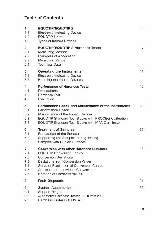
Table of Contents
1 EQUOTlP/EQUOTlP 2 41.1 Electronic Indicating Device1.2 EQUOTlP-Units1.3 Types of Impact Devices
2 EQUOTlP/EQUOTlP 2-Hardness Tester 72.1 Measuring Method2.2 Examples of Application2.3 Measuring Range2.4 Technical Data
3 Operating the Instruments 113.1 Electronic Indicating Device3.2 Handling the Impact Devices
4 Perfomance of Hardness Tests 194.1 Preparations4.2 Hardness Test4.3 Evaluation
5 Perfomance Check and Maintenance of the Instruments 205.1 Performance Check5.2 Maintenance of the Impact Devices5.3 EQUOTIP Standard Test Blocks with PROCEQ-Calibration5.4 EQUOTIP Standard Test Blocks with MPA-Certificate
6 Treatment of Samples 236.1 Preparation of the Surface6.2 Supporting the Samples during Testing6.3 Samples with Curved Surfaces
7 Conversion with other Hardness Numbers 267.1 EQUOTIP Conversion-Tables7.2 Conversion Deviations7.3 Deviations from Conversion Values7.4 Setup of Plant-lnternal Conversion Curves7.5 Application of Individual Conversions7.6 Notation of Hardness Values
8 Fault Diagnosis 31
9 System Accessories 329.1 Support Rings9.2 Automatic Hardness Tester EQUOmatic 29.3 Hardness Tester EQUOSTAT

4
1 Operating keypad 5 Signal output RS 232 2 Large LCD display for 6 Ext. power supply 9 VDC
hardness values and 7 Battery compartementrepresentation of actual 8 Battery compartement covermeasurements 9 Housing upper part
3 Input-socket 3-pole 10 Housing lower part4.1 Input-socket 2-pole4.2 Input-socket 6-pole for
EQUOSTAT Probe R5
>
9
2
10
7/8
6
5
4.1
3
4.2
1
1 EQUOTlP/EQUOTlP 2
1.1 Electronic Indicating Devices
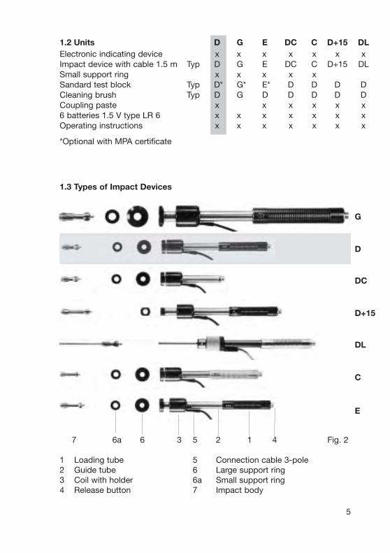
1.2 Units D G E DC C D+15 DLElectronic indicating device x x x x x x xImpact device with cable 1.5 m Typ D G E DC C D+15 DLSmall support ring x x x x xSandard test block Typ D* G* E* D D D DCleaning brush Typ D G D D D D DCoupling paste x x x x x x6 batteries 1.5 V type LR 6 x x x x x x xOperating instructions x x x x x x x
*Optional with MPA certificate
1.3 Types of Impact Devices
5
7 6a 6 3 5 2 1 4 Fig. 2
1 Loading tube 5 Connection cable 3-pole2 Guide tube 6 Large support ring3 Coil with holder 6a Small support ring4 Release button 7 Impact body
G
D
DC
D+15
DL
C
E
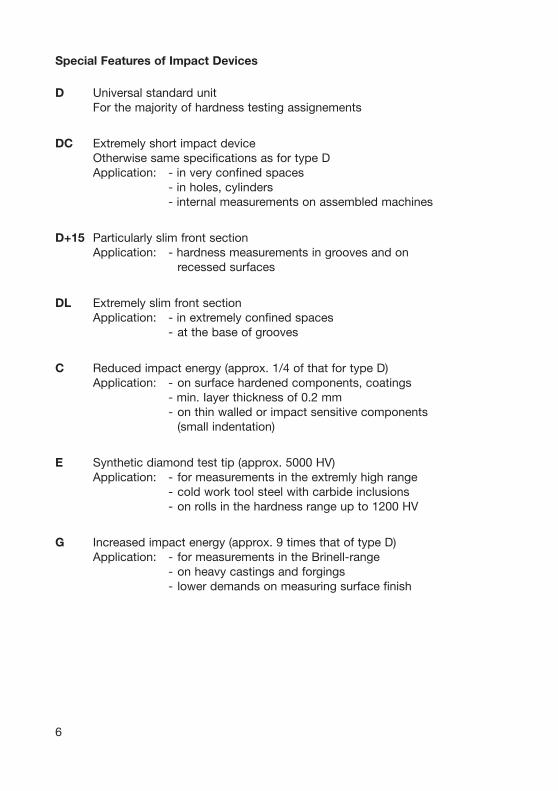
Special Features of Impact Devices
D Universal standard unitFor the majority of hardness testing assignements
DC Extremely short impact deviceOtherwise same specifications as for type DApplication: - in very confined spaces
- in holes, cylinders- internal measurements on assembled machines
D+15 Particularly slim front sectionApplication: - hardness measurements in grooves and on
recessed surfaces
DL Extremely slim front sectionApplication: - in extremely confined spaces
- at the base of grooves
C Reduced impact energy (approx. 1/4 of that for type D)Application: - on surface hardened components, coatings
- min. Iayer thickness of 0.2 mm- on thin walled or impact sensitive components
(small indentation)
E Synthetic diamond test tip (approx. 5000 HV)Application: - for measurements in the extremly high range
- cold work tool steel with carbide inclusions- on rolls in the hardness range up to 1200 HV
G Increased impact energy (approx. 9 times that of type D)Application: - for measurements in the Brinell-range
- on heavy castings and forgings- lower demands on measuring surface finish
6
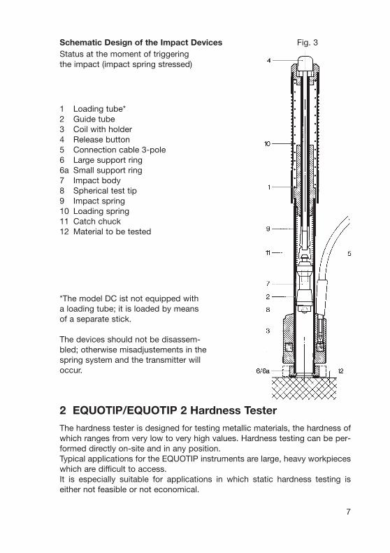
Schematic Design of the Impact DevicesStatus at the moment of triggeringthe impact (impact spring stressed)
1 Loading tube*2 Guide tube3 Coil with holder4 Release button5 Connection cable 3-pole6 Large support ring6a Small support ring7 Impact body8 Spherical test tip9 Impact spring10 Loading spring11 Catch chuck12 Material to be tested
*The model DC ist not equipped witha loading tube; it is loaded by means of a separate stick.
The devices should not be disassem-bled; otherwise misadjustements in thespring system and the transmitter willoccur.
7
2 EQUOTlP/EQUOTIP 2 Hardness Tester
The hardness tester is designed for testing metallic materials, the hardness ofwhich ranges from very low to very high values. Hardness testing can be per-formed directly on-site and in any position.Typical applications for the EQUOTIP instruments are large, heavy workpieceswhich are difficult to access.It is especially suitable for applications in which static hardness testing iseither not feasible or not economical.
Fig. 3
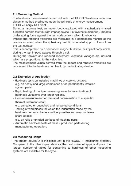
2.1 Measuring MethodThe hardness measurement carried out with the EQUOTIP hardness tester is adynamic method predicated upon the principle of energy measurement;EQUO = Energy-QUOtient.During a hardness test, an impact body, equipped with a spherically shapedtungsten carbide test tip (with impact device E of synthetic diamond), impactsunder spring force against the test surface from which it rebounds.Impact and rebound velocities are measured in a contactless manner at theprecise moment, when the spherically test tip is located approx. 1 mm fromthe test surface.This is accomplished by a permanent magnet built into the impact body which,during the test impact, passes through a coil.During the forward and rebound movement, electrical voltages are inducedwhich are proportional to the velocities.The measurement values derived from the impact and rebound velocities areprocessed into the hardness number L by the indicating device.
2.2 Examples of Application- Hardness tests on installed machines or steel-structures;
e.g. on heavy and large workpieces or on permanently installedsystem parts.
- Rapid testing of multiple measuring areas for examination ofhardness variations over larger regions.
- Control measurement for the rapid determination of a specificthermal treatment result;e.g. annealed or quenched and tempered conditions.
- Testing of workpieces for which the indentation made by thehardness test must be as small as possible and may not leavesharp edges;e.g. on rolls or grinded surfaces of machine parts.
- Automatic hardness tests of mass - produced parts duringmanufacturing operation.
2.3 Measuring RangeThe impact device D is the basic unit in the «EQUOTIP measuring system».Compared to the other impact devices, the most universal applicability and thelargest number of tables for converting to hardness of other measuringsystems are available for this type.
8
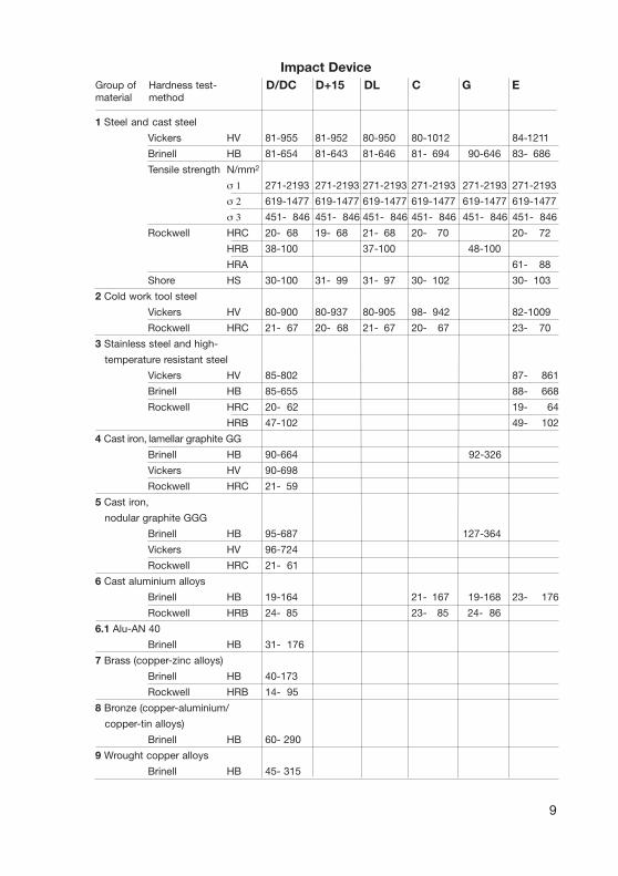
1 Steel and cast steel
Vickers HV 81-955 81-952 80-950 80-1012 84-1211
Brinell HB 81-654 81-643 81-646 81- 694 90-646 83- 686
Tensile strength N/mm2
σ 1 271-2193 271-2193 271-2193 271-2193 271-2193 271-2193
σ 2 619-1477 619-1477 619-1477 619-1477 619-1477 619-1477
σ 3 451- 846 451- 846 451- 846 451- 846 451- 846 451- 846
Rockwell HRC 20- 68 19- 68 21- 68 20- 70 20- 72
HRB 38-100 37-100 48-100
HRA 61- 88
Shore HS 30-100 31- 99 31- 97 30- 102 30- 103
2 Cold work tool steel
Vickers HV 80-900 80-937 80-905 98- 942 82-1009
Rockwell HRC 21- 67 20- 68 21- 67 20- 67 23- 70
3 Stainless steel and high-
temperature resistant steel
Vickers HV 85-802 87- 861
Brinell HB 85-655 88- 668
Rockwell HRC 20- 62 19- 64
HRB 47-102 49- 102
4 Cast iron, lamellar graphite GG
Brinell HB 90-664 92-326
Vickers HV 90-698
Rockwell HRC 21- 59
5 Cast iron,
nodular graphite GGG
Brinell HB 95-687 127-364
Vickers HV 96-724
Rockwell HRC 21- 61
6 Cast aluminium alloys
Brinell HB 19-164 21- 167 19-168 23- 176
Rockwell HRB 24- 85 23- 85 24- 86
6.1 Alu-AN 40
Brinell HB 31- 176
7 Brass (copper-zinc alloys)
Brinell HB 40-173
Rockwell HRB 14- 95
8 Bronze (copper-aluminium/
copper-tin alloys)
Brinell HB 60- 290
9 Wrought copper alloys
Brinell HB 45- 315
9
Impact DeviceGroup of Hardness test-material method
D/DC D+15 DL C G E
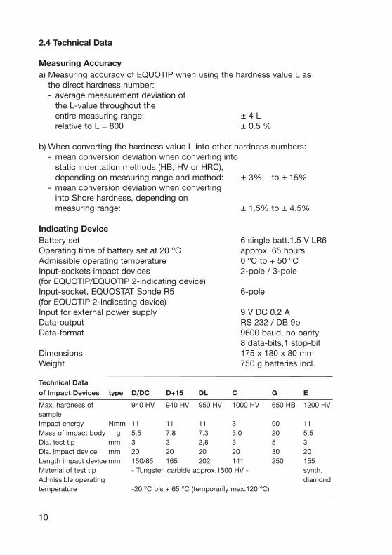
2.4 Technical Data
Measuring Accuracya) Measuring accuracy of EQUOTIP when using the hardness value L as
the direct hardness number:- average measurement deviation of
the L-value throughout theentire measuring range: ± 4 Lrelative to L = 800 ± 0.5 %
b) When converting the hardness value L into other hardness numbers:- mean conversion deviation when converting into
static indentation methods (HB, HV or HRC),depending on measuring range and method: ± 3% to ± 15%
- mean conversion deviation when convertinginto Shore hardness, depending onmeasuring range: ± 1.5% to ± 4.5%
Indicating DeviceBattery set 6 single batt.1.5 V LR6Operating time of battery set at 20 ºC approx. 65 hoursAdmissible operating temperature 0 ºC to + 50 ºCInput-sockets impact devices 2-pole / 3-pole(for EQUOTIP/EQUOTIP 2-indicating device)Input-socket, EQUOSTAT Sonde R5 6-pole(for EQUOTIP 2-indicating device)Input for external power supply 9 V DC 0.2 AData-output RS 232 / DB 9pData-format 9600 baud, no parity
8 data-bits,1 stop-bitDimensions 175 x 180 x 80 mmWeight 750 g batteries incl.
Technical Dataof Impact Devices type D/DC D+15 DL C G E
Max. hardness of 940 HV 940 HV 950 HV 1000 HV 650 HB 1200 HVsampleImpact energy Nmm 11 11 11 3 90 11Mass of impact body g 5.5 7.8 7.3 3.0 20 5.5Dia. test tip mm 3 3 2,8 3 5 3Dia. impact device mm 20 20 20 20 30 20Length impact device mm 150/85 165 202 141 250 155Material of test tip - Tungsten carbide approx.1500 HV - synth.Admissible operating diamondtemperature -20 ºC bis + 65 ºC (temporarily max.120 ºC)
10
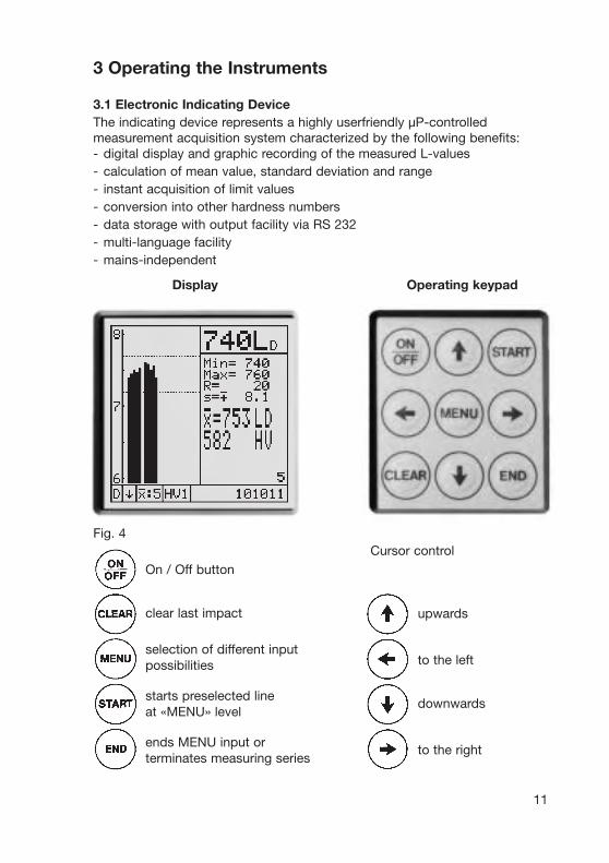
3 Operating the Instruments
3.1 Electronic Indicating DeviceThe indicating device represents a highly userfriendly µP-controlledmeasurement acquisition system characterized by the following benefits:- digital display and graphic recording of the measured L-values- calculation of mean value, standard deviation and range- instant acquisition of limit values- conversion into other hardness numbers- data storage with output facility via RS 232 - multi-language facility- mains-independent
Display Operating keypad
11
Fig. 4Cursor control
On / Off button
clear last impact
selection of different inputpossibilities
starts preselected lineat «MENU» level
ends MENU input orterminates measuring series
upwards
to the left
downwards
to the right
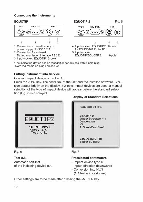
1 Connection external battery or 4 Input-socket, EQUOTIP2: 6-pole power supply 9 V DC 0.2 A for EQUOSTAT Probe R5
2 Connection for external 5 Input-socket,Data-transmission Interface RS 232 EQUOTIP/EQUOTIP2: 3-pole*
3 Input-socket, EQUOTIP: 2-pole
*The indicating device has an recognition for devices with 3-pole plug.Note red marks on plug and socket!
Putting Instrument into ServiceConnect impact device or probe R5.Press the «ON» key. The serial No. of the unit and the installed software - ver-sion appear briefly on the display. If 2-pole impact devices are used, a manualselection of the type of impact device will appear before the standard selec-tion (Fig. 7) is displayed.
Display of Standard Selections
12
Fig. 6 Fig. 7
Test o.k.: Preselected parameters:Automatic self-test - Impact device type Dof the indicating device o.k. - Inpact direction downwards
- Conversion into HV/1(1: Steel and cast steel)
Batt. still 24 Hrs.
Device = DImpact Direction = "ConversionHV1: Steel/Cast Steel
Confirm by STARTSelect by MENU
Other settings are to be made after pressing the «MENU» key.
Connecting the Instruments
EQUOTIP EQUOTIP 2 Fig. 5
1 2 4 51 2 3 5
13
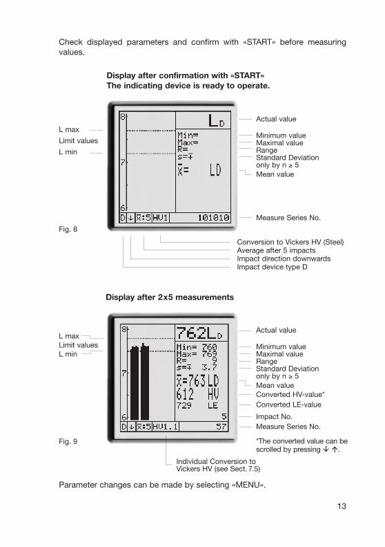
Parameter changes can be made by selecting «MENU».
Display after 2x5 measurements
Fig. 9
L max
Limit values
L min
Fig. 8
Display after confirmation with «START»The indicating device is ready to operate.
Actual value
Minimum valueMaximal valueRangeStandard Deviationonly by n ≥ 5Mean value
Measure Series No.
Conversion to Vickers HV (Steel)Average after 5 impactsImpact direction downwardsImpact device type D
Actual value
Minimum valueMaximal valueRangeStandard Deviationonly by n ≥ 5Mean valueConverted HV-value*Converted LE-value
Impact No.Measure Series No.
*The converted value can bescrolled by pressing " #.
Check displayed parameters and confirm with «START» before measuringvalues.
L maxLimit valuesL min
Individual Conversion toVickers HV (see Sect. 7.5)

Preselections MENU Selection of Date/Time
14
Fig. 10 Fig. 11
Preselected settings remain stored after the unit is switched off and are dis-played on switching once again. Where several settings are being made, thenext selection is to be made with «MENU».
Selection of Impact Direction Selection of Mean Value
Fig. 12 Fig. 13
The displayed values are auto- With preselection (n = 0), thematically corrected with pre- measuring series has to beselection of impact directions terminated by «END».other than vertical downwards.
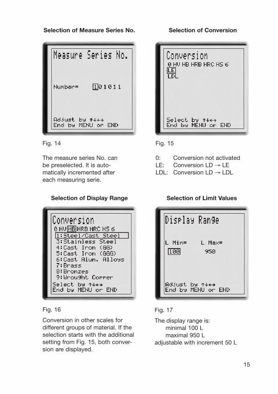
Fig. 14 Fig. 15
The measure series No. can 0: Conversion not activatedbe preselected. lt is auto- LE: Conversion LD → LEmatically incremented after LDL: Conversion LD → LDLeach measuring serie.
15
Selection of Measure Series No. Selection of Conversion
Fig. 17
The display range is:minimal 100 Lmaximal 950 L
adjustable with increment 50 L
Selection of Display Range Selection of Limit Values
Fig. 16
Conversion in other scales for different groups of material. If the selection starts with the additional setting from Fig. 15, both conver-sion are displayed.
Selection of data Output Locking the Settings
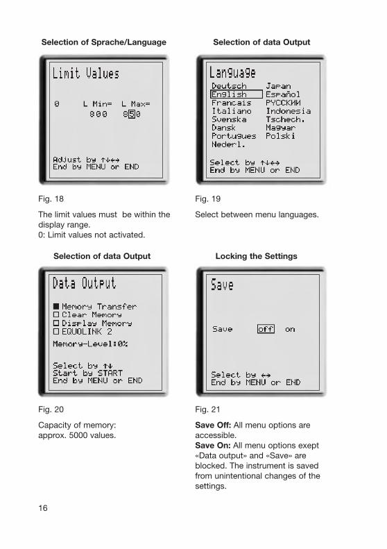
Fig. 20 Fig. 21
Capacity of memory: Save Off: All menu options are approx. 5000 values. accessible.
Save On: All menu options exept «Data output» and «Save» are blocked. The instrument is savedfrom unintentional changes of the settings.
16
Selection of Sprache/Language Selection of data Output
Fig. 18 Fig. 19
The limit values must be within the Select between menu languages.display range.0: Limit values not activated.

$ Memory transfer with software EQUOLINK 2The EQUOLINK 2 software is a program for transferring the memorised datafrom the indicating device to an IBM- or compatible personal computer(on WlNDOWS-level). Following items are required:- EQUOTIP indicating device- IBM-PC or compatible PC (W95/W98/NT4.0/W2000/XP)- Original EQUOLlNK-cable to RS 232 from serial No. 714-0001 to
serial No. 898-2080- Original transfer cable from serial No. 918-0001- EQUOLINK 2-software diskProcedure for installation:- Go to operating level «Program Manager» at computer- Insert EQUOLINK 2-disk in disk drive A- Information to the program by A:\ lnstall.TXT
- Start program EQUOLINK 2 by A:\ Setup
The program EQUOLINK 2 contains all further information on data transfer andrequests the next step via a dialog.Remark: The memory at EQUOTIP indicating device contains approx. 5000values. With memory fullfilled, previously stored data are overwritten.$ Clear MemoryMemory is cleared by additional confirmation with «START».$ Display Memory- Measured Series No., type of impact device, impact direction and type of
preselected conversion.- Display of measured values consequently to the measurements.$ EQUOlink 2- Enter the key code and press key «END» (Fig. 22 and Fig. 23).- The key code is depending of the SN No. of the electronic device.
17
Fig. 22 Fig. 23
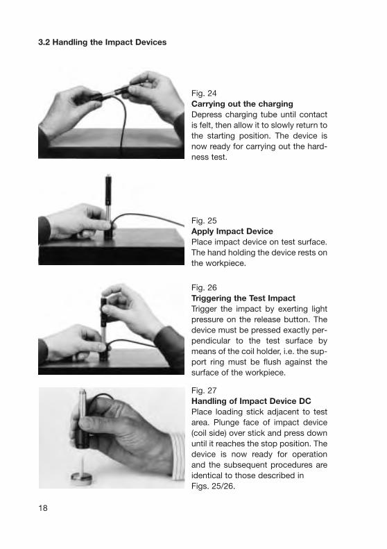
Fig. 24Carrying out the chargingDepress charging tube until contactis felt, then allow it to slowly return tothe starting position. The device isnow ready for carrying out the hard-ness test.
Fig. 25Apply Impact DevicePlace impact device on test surface.The hand holding the device rests onthe workpiece.
Fig. 26Triggering the Test ImpactTrigger the impact by exerting lightpressure on the release button. Thedevice must be pressed exactly per-pendicular to the test surface bymeans of the coil holder, i.e. the sup-port ring must be flush against thesurface of the workpiece.
Fig. 27 Handling of Impact Device DCPlace loading stick adjacent to testarea. Plunge face of impact device(coil side) over stick and press downuntil it reaches the stop position. Thedevice is now ready for operationand the subsequent procedures areidentical to those described in Figs. 25/26.
18
3.2 Handling the Impact Devices
4 Performance of Hardness Tests
4.1 Preparationsa) Prepare surface of the workpiece according to the procedures outlined in
Sect. 6.1b) Observe the recommendations in Sect. 6.2 concerning supporting of the
samples.c) Carry out the performance check discussed in Sect. 5.1
4.2 Hardness Testsa) Preselection at indicating device according to Sect. 3.1.b) Operate the impact device according to Sect. 3.2c) Number of impacts per measuring area
- Each measuring area should be tested by at least 3 to 5 impacts.- Do not impact the same point more than once.- Display on the indicating unit of mean value L, standard deviation s and
range R.- If the range within the same measuring area exceeds R≥ 30 L, check whet-
her the surface of the sample has been adequately ground or whether thesample yields or flexes during the test impact.
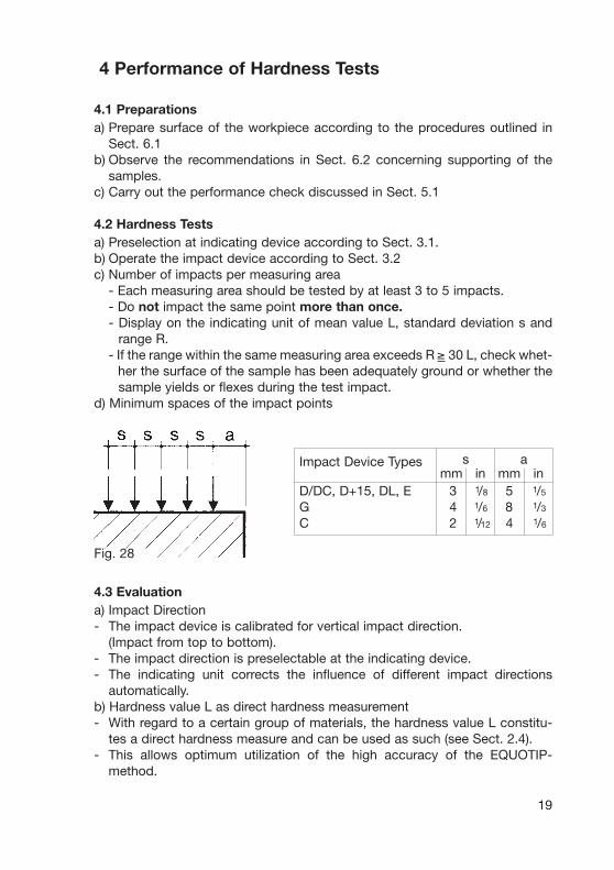
d) Minimum spaces of the impact points
4.3 Evaluationa) Impact Direction- The impact device is calibrated for vertical impact direction.
(Impact from top to bottom).- The impact direction is preselectable at the indicating device.- The indicating unit corrects the influence of different impact directions
automatically.b) Hardness value L as direct hardness measurement- With regard to a certain group of materials, the hardness value L constitu-
tes a direct hardness measure and can be used as such (see Sect. 2.4).- This allows optimum utilization of the high accuracy of the EQUOTIP-
method.
Impact Device Typesmm in mm in
D/DC, D+15, DL, E 3 1/8 5 1/5
G 4 1/6 8 1/3
C 2 1/12 4 1/6
Fig. 28
19
s a

c) Conversion to hardness values of other methods- With a certain loss of accuracy (conversion deviation), the hardness value
L can be converted into equivalent hardness values of other measuringmethods such as Brinell, Vickers, Rockwell C, Shore etc.
- These conversions are selectable at the indicating device.- At the end of each test-cycle the calculated mean value L is indicated as
well as the hardness value of the other hardness method selected (scrollingpossible).
- By preselection on the indicating device the different methods and group ofmaterials are to consider.
5 Performance Check and Maintenanceof the Instruments
5.1 Performance CheckThe Performance Check controls the mechanical and electronic functions ofthe impact device and the indicating unit. It is accomplished by measuring thehardness value L of the standard test block applicable to the particular type ofimpact device (see Sect. 5.3/5.4).
Carrying out the Performance Check:- Clean an impact device according to Sect. 5.2- Perform impact tests on standard test block. As a rule, 3 to 5 impacts even-
ly distributed on the test area, are sufficient. The distance between impactlocation and outer edge of the standard test block should be according to Fig. 28.
- Read off mean value L and compare with reference L-value. The instrumentoperates properly if the indicated mean L-value x falls within the referencerange and the range R does not exceed 16 L-units.
If the deviation of the mean value from the reference L-value exceeds ±12 L-units, the instrument should no longer be used and must be returned to themanufacturer for servicing. With smaller deviations, the L-value can be correc-ted, until the next service, according to the following formula:
Lk = L. Lref example Lk= 582 . 764= 574 L
Lactual 774Lk = corrected mean value 574 LL = read-off mean value during testing a sample 582 LLref = reference value from standard test block 764 LLactual = actual value when carrying out measurement 774 L
operation at the test block
20
Lk = L. Example: Lk= 582 .

21
Frequency of Conducting Operational Testsa) Test instrument is used continuously:- at least once per day- the latest after 1000 impactsb) Test instrument is used periodically:- before and after conducting a test series
5.2 Maintenance of the Impact DevicesThe devices do not require any particular care other than periodic cleaning ofthe impact body and the guide tube after performing approximately1000-2000 tests.During cleaning, the following procedures need to be observed:- Unscrew support ring and remove impact body from guide tube- Clean off any dirt and metallic dust from impact body and test tip- Clean guide tube with the special brush provided- Do not apply oil to any parts for the impact device
5.3 EQUOTIP Standard Test Blocks with PROCEQ-CalibrationEQUOTIP standard test blocks are calibrated with standard devices accordingto the EQUOTIP calibration basis by PROCEQ SA, they are equipped by a cali-bration certificate.The EQUOTIP calibration basis corresponds to the standard of the QualityManagement System ISO 9001 : 1994 / chapt. 11 and is permanently ins-pected.The strict observance of the values marked on the standard test block gua-rantees the correct functions of the impact device and the indicating unitthroughout the entire measuring range.Type, identification and reference values engraved on the standard testblocks see examples below.
Standard Test Block Type Ddia. 90 x 56 mm, dia 3.6 x 2.2 inches, weight 2.8 kg suitable for impact devices: D/DC, D+15, C, DL
serial no.(traceability)
reference-values(nominal range)
Vickers(conversion value)
Standard Test Block Type Gdia.120 x 70 mm, dia 4.75 x 2.75 inches, weight 6.2 kg suitable for impact devices: G, (D/DC)
serial no.(traceability)
reference-values(nominal range)
Brinell (F=30D2)(conversion value)
D.1443.9755B LD=766±6 (LD+15=772±6/LC=827±6/LDL=833±6) HV100=610±15
G.161.9645 A LG=579±6 (LD=620±6) HB5/750=350±8
Remark: Densely impacted standard test blocks cannot be restored bygrinding. Reason: Through grinding, the original hardness is altered in anuneven and uncontrolled manner. Therefore the standard test blocks can neit-her be calibrated for a new mean value nor for an acceptable ± tolerance.
22
Standard Test Block Typ D/MPAdia. 90 x 56 mm, dia 3.6 x 2.2 inches, weight 2.8 kgsuitable for impact device: D
serial no.(traceability)
reference-value(nominal range)
Vickers/MPA(calibrated value)
The value in parantheses applies to impact devices D and DC, provided theyare used only within the Brinell range. For checking these devices throughouttheir entire measuring range (up to L=900 or 950 HV), the standard test blockstype D must be used.
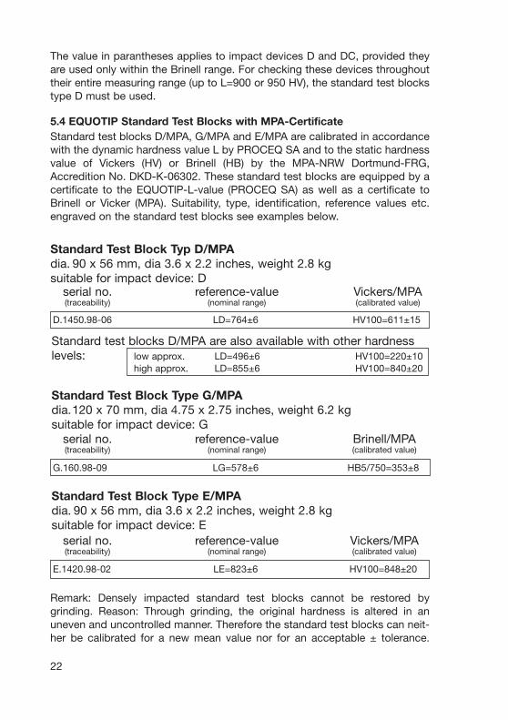
5.4 EQUOTIP Standard Test Blocks with MPA-CertificateStandard test blocks D/MPA, G/MPA and E/MPA are calibrated in accordancewith the dynamic hardness value L by PROCEQ SA and to the static hardnessvalue of Vickers (HV) or Brinell (HB) by the MPA-NRW Dortmund-FRG,Accredition No. DKD-K-06302. These standard test blocks are equipped by acertificate to the EQUOTlP-L-value (PROCEQ SA) as well as a certificate toBrinell or Vicker (MPA). Suitability, type, identification, reference values etc.engraved on the standard test blocks see examples below.
D.1450.98-06 LD=764±6 HV100=611±15
Standard test blocks D/MPA are also available with other hardnesslevels: low approx. LD=496±6 HV100=220±10
high approx. LD=855±6 HV100=840±20
Standard Test Block Type G/MPAdia.120 x 70 mm, dia 4.75 x 2.75 inches, weight 6.2 kgsuitable for impact device: G
serial no.(traceability)
reference-value(nominal range)
Brinell/MPA(calibrated value)
G.160.98-09 LG=578±6 HB5/750=353±8
Standard Test Block Type E/MPAdia. 90 x 56 mm, dia 3.6 x 2.2 inches, weight 2.8 kgsuitable for impact device: E
serial no.(traceability)
reference-value(nominal range)
Vickers/MPA(calibrated value)
E.1420.98-02 LE=823±6 HV100=848±20
23
6 Treatment of Samples
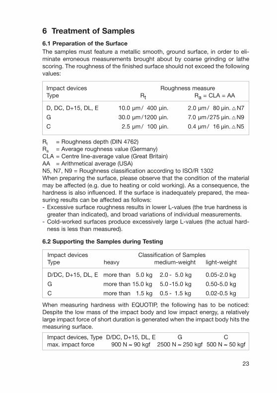
6.1 Preparation of the SurfaceThe samples must feature a metallic smooth, ground surface, in order to eli-minate erroneous measurements brought about by coarse grinding or lathescoring. The roughness of the finished surface should not exceed the followingvalues:
Rt = Roughness depth (DIN 4762)Ra = Average roughness value (Germany)CLA = Centre line-average value (Great Britain)AA = Arithmetical average (USA)N5, N7, N9 = Roughness classification according to ISO/R 1302When preparing the surface, please observe that the condition of the materialmay be affected (e.g. due to heating or cold working). As a consequence, thehardness is also influenced. If the surface is inadequately prepared, the mea-suring results can be affected as follows:- Excessive surface roughness results in lower L-values (the true hardness is
greater than indicated), and broad variations of individual measurements.- Cold-worked surfaces produce excessively large L-values (the actual hard-
ness is less than measured).
6.2 Supporting the Samples during Testing
When measuring hardness with EQUOTIP, the following has to be noticed:Despite the low mass of the impact body and low impact energy, a relativelylarge impact force of short duration is generated when the impact body hits themeasuring surface.
Impact devices Classification of SamplesType heavy medium-weight light-weight
D/DC, D+15, DL, E more than 5.0 kg 2.0 - 5.0 kg 0.05-2.0 kg
G more than 15.0 kg 5.0 -15.0 kg 0.50-5.0 kg
C more than 1.5 kg 0.5 - 1.5 kg 0.02-0.5 kg
Impact devices Roughness measureType Rt Ra = CLA = AA
D, DC, D+15, DL, E 10.0 µm/ 400 µin. 2.0 µm/180 µin.�N7
G 30.0 µm/1200 µin. 7.0 µm/275 µin.�N9
C 2.5 µm/0100 µin. 0.4 µm/116 µin.�N5
Impact devices, Typemax. impact force
D/DC, D+15, DL, E900 N ≈ 90 kgf
G2500 N ≈ 250 kgf
C500 N ≈ 50 kgf

24
For heavy samples of compact shape, no particular precautions are necessary.Smaller and lighter samples or workpieces yield or flex under this force, pro-ducing L-values which are too small and of excessively large variation. Even withbig or heavy workpieces it is possible for thin-wall regions or thinner protrudingparts to yield upon impact. Depending on the frequency of the resilient yieldingaction, the measured L-value may be too small or too large. In many situations,potential problems can be checked in the following manner:
a) Medium-weight samples and also heavier samples with protruding parts orthin walls should be placed on a solid support in such a manner that theydo not move or flex during the test impact.
b) Light-weight samples should be rigidly «coupled» with a non-yielding sup-port such as a heavy base plate. Clamping in a vice is of no value, since thesamples become exposed to stress and because complete rigidity is neverattained. As a rule, the measured L-values would be too small and showexcessive variations.
For coupling purposes, a thin layer of coupling paste is to be applied to thecontact surface of the sample. Subsequently, the sample should be firmlypressed against the surface of the base plate by moving it with a circularmotion (mutual rubbing of the mating surfaces). The coupling process hasbeen carried out properly, if there is still no metallic contact between the parts.During testing, the impact occurs so quickly that the thin layer does not havetime to yield. The sample and the support behave as if they were absolutelyrigidly interconnected.
For the coupling operation, the following prerequisites must be fulfilled:- The contact surface of the sample and the surface of the base plate must be
flat, plane parallel and ground.- The direction of the test impact must be perpendicular to the coupled
surface.
Impact devices, types Minimum sample thickness for coupling
D, DC, D+15, DL, E 3 mm / 1/8 inchG 10 mm / 1/2,5 inchC 1 mm / 1/25 inch

25
Proper Coupling:Proper coupling requires a little experience. Insufficiently coupled samplesproduce large variations of individual measurements, L-values which are toolow and the operation is characterized by a rattling noise upon impact of thetest tip. Example for coupling a test piece with a base plate
Fig. 29Application of the coupling paste(as thin as possible)
Fig. 30Mutual rubbing of both parts whilefirmly pressing the sample againstthe base plate
Fig. 31A particular advantage of coupling isthe possibility of obtaining a veryuniform, rigid connection betweenthe sample and the support, totallyeliminating stresses at the samplesurface. The resulting variation inmeasured values is very low.
26
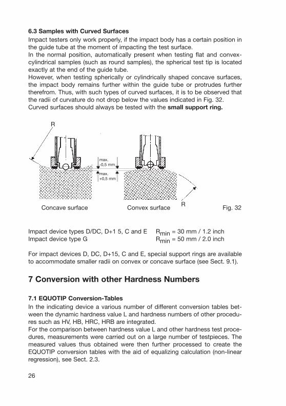
6.3 Samples with Curved SurfacesImpact testers only work properly, if the impact body has a certain position inthe guide tube at the moment of impacting the test surface.In the normal position, automatically present when testing flat and convex-cylindrical samples (such as round samples), the spherical test tip is locatedexactly at the end of the guide tube.However, when testing spherically or cylindrically shaped concave surfaces,the impact body remains further within the guide tube or protrudes furthertherefrom. Thus, with such types of curved surfaces, it is to be observed thatthe radii of curvature do not drop below the values indicated in Fig. 32.Curved surfaces should always be tested with the small support ring.
R
Impact device types D/DC, D+1 5, C and E Rmin = 30 mm / 1.2 inchImpact device type G Rmin = 50 mm / 2.0 inch
For impact devices D, DC, D+15, C and E, special support rings are availableto accommodate smaller radii on convex or concave surface (see Sect. 9.1).
7 Conversion with other Hardness Numbers
7.1 EQUOTIP Conversion-TablesIn the indicating device a various number of different conversion tables bet-ween the dynamic hardness value L and hardness numbers of other procedu-res such as HV, HB, HRC, HRB are integrated.For the comparison between hardness value L and other hardness test proce-dures, measurements were carried out on a large number of testpieces. Themeasured values thus obtained were then further processed to create theEQUOTIP conversion tables with the aid of equalizing calculation (non-linearregression), see Sect. 2.3.
R Concave surface Convex surface Fig. 32
max.-0,5 mm
max.+0,5 mm
7.2 Conversion DeviationsThe conversion deviation is the variance resulting from the comparison of mea-suring values observed with different hardness testing methods. It includes2 components. The major share is caused by the fact that there is no clear phy-sical relationship between the various methods. The second componentresults from the circumstance that the comparison of hardness values (e.g.L-value and Brinell) also includes the measuring deviation of the method beingcompared to.Therefore, a conversion between hardness values contains inaccuracies fromthe outset. This applies not only to conversion of the L-value into static inden-tation hardness values, but also for converting from one static hardness mea-suring method to another. The conversion deviations (± HB, ± HV, etc.) indica-ted in the «conversion tables» represent «standard deviations», i.e. 68% of allmaterials tested to date fell within the specified variance range.
7.3 Deviation from Conversion ValuesDeviations from the values in the conversion can occur with the following steelqualities:
High-Alloyed Steels- In high-speed tool steels, hotwork steels, and ledeburite chromium steels
(group of high-carbon cold-work steels), the hard materials embedded in thematrix (ledeburite tungsten carbide e.g. type M7C3 and M6C) cause a localincrease of the E-modulus, resulting in L-values which are actually too low.A typical representative of this group is the tool steel for cold work X210Cr12(Material No.1.2080) containing 2.1% C and 12% Cr (see special conver-sions for impact devices D, C, D+15 and E).
Cold Work-Hardened Steels- Drawn and in part also rolled steels frequently lead to excessively high
L-values due to the pronounced cold-worked regions near the surface whichsimulate higher than actual hardness. Such steels should always be testedover their entire cross-section.
Magnetic Steels- When testing magnetic materials, the velocity transmitter in the impact body
is briefly influenced by their magnetic field. Therefore, slight deviations of themeasured L-values may occur.
Surface-Hardened Steels- Surface-hardened steels and especially case-hardened steels produce
L- values which are too low when case-hardening depth is small because oftheir soft core.
27
7.4 Setup of Plant-lnternal Conversion CurvesFor the special situations mentioned in Sect. 7.3, or when testing materials forwhich no generally applicable conversions are available, the user can developindividual conversion tables.When developing conversion curves, the following points must be observed:- The sample surface must be prepared very carefully.- If possible, samples should be of a size which makes coupling to a support
base unnecessary.- The correct readout of the EOUOTIP hardness tester is to be checked
against the standard test block for each test series.- The function of the static hardness testing machines and the correct optical
evaluation of the indentations is to be checked for each test series, with theaid of standard test blocks of corresponding measuring range.
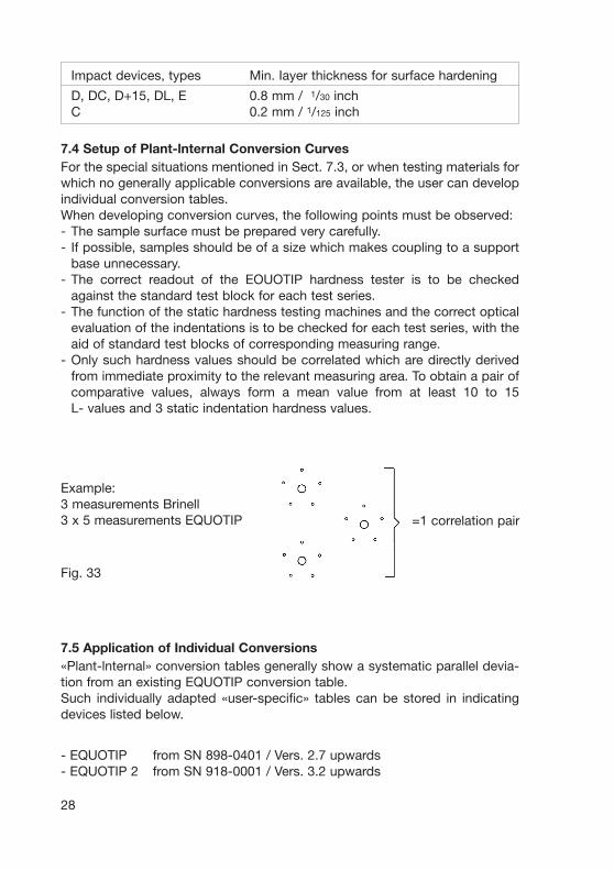
- Only such hardness values should be correlated which are directly derivedfrom immediate proximity to the relevant measuring area. To obtain a pair ofcomparative values, always form a mean value from at least 10 to 15L- values and 3 static indentation hardness values.
28
=1 correlation pair
Example:3 measurements Brinell3 x 5 measurements EQUOTIP
Fig. 33
7.5 Application of Individual Conversions«Plant-lnternal» conversion tables generally show a systematic parallel devia-tion from an existing EQUOTIP conversion table.Such individually adapted «user-specific» tables can be stored in indicatingdevices listed below.
- EQUOTIP from SN 898-0401 / Vers. 2.7 upwards- EQUOTIP 2 from SN 918-0001 / Vers. 3.2 upwards
Impact devices, types Min. Iayer thickness for surface hardening
D, DC, D+15, DL, E 0.8 mm / 1/30 inchC 0.2 mm / 1/125 inch
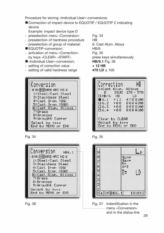
Procedure for storing «Individual User»-conversions:$Connection of impact device to EQUOTIP / EQUOTIP 2 indicating
device.Example: impact device type D
- preselection menu «Conversion» Fig. 34- preselection of hardness procedure HB- preselection of group of material: 6: Cast Alum. Alloys$EQUOTlP-conversion: HB/6- activation of menu «Correction» Fig. 35
by keys «CLEAR» «START» press keys simultaneously$«Individual User»-conversion: HB/6.1 Fig. 36- setting of correction value + 12 HB- setting of valid hardness range 470 LD ± 100
29
Fig. 34 Fig. 35
Fig. 36 Fig. 37 Indentification in themenu «Conversion»and in the status-line
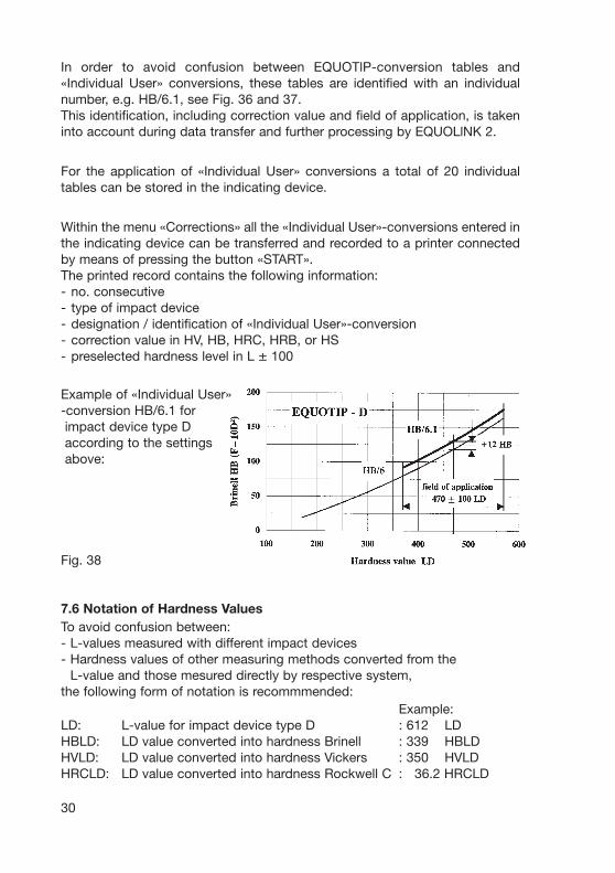
In order to avoid confusion between EQUOTlP-conversion tables and«Individual User» conversions, these tables are identified with an individualnumber, e.g. HB/6.1, see Fig. 36 and 37.This identification, including correction value and field of application, is takeninto account during data transfer and further processing by EQUOLlNK 2.
For the application of «Individual User» conversions a total of 20 individualtables can be stored in the indicating device.
Within the menu «Corrections» all the «Individual User»-conversions entered inthe indicating device can be transferred and recorded to a printer connectedby means of pressing the button «START».The printed record contains the following information:- no. consecutive- type of impact device- designation / identification of «Individual User»-conversion- correction value in HV, HB, HRC, HRB, or HS- preselected hardness level in L ± 100
Example of «Individual User» -conversion HB/6.1 forimpact device type Daccording to the settings above:
Fig. 38
7.6 Notation of Hardness ValuesTo avoid confusion between:- L-values measured with different impact devices- Hardness values of other measuring methods converted from the
L-value and those mesured directly by respective system, the following form of notation is recommmended:
Example:LD: L-value for impact device type D : 612 LDHBLD: LD value converted into hardness Brinell : 339 HBLDHVLD: LD value converted into hardness Vickers : 350 HVLDHRCLD: LD value converted into hardness Rockwell C : 36.2 HRCLD
30

8 Fault DiagnosisIndication Cause Possible Remedy
No digital readout - dead batteries- batteries
improperly poled- no contact at nega- correct defect
tive battery pole- no battery in holder- indicating device
too cold(temp. <0 °C) warm up device
Digital display does - poor cable contact plug in cable com-not move or cable broken pletely, or even pos-
- the tested material sibly replace cableis extremelyhomogenous
No impact occurs - impact body is notor improperlylocated in the correct defectimpact device
- impact body does service the catchnot release or chuck or releasecannot be loaded mechanism
Marked deviation of - measuring area prepare sampleindividual L-values or inadequately according toL-values constantly prepared Section 6.1too low - the tested material
is extremely inhomo-genous or porous
- sample is insuffi- support sampleciently supported according to
Section 6.2
- sample exhibitslarge local hardnessdifferences, e.g. atthe transition seamto the base material
31
}
Indication Cause Possible Remedy
- impact direction Please seehas been changed corrections forbetween the other impactindividual impacts directions
L-values at the stan- - impact device clean impact devicedard test block con- contaminated according tostantly too low Section 5.2
- spherical test tip replace impactcracked (e.g. due bodyto impact againsttungsten carbide)
- support ring does replace supportnot have rubber pad ring
L-values at the ring - spherical test tip replace impactstandard test block flattened (impact bodyconstantly too high against tungsten
carbide, wear)- standard test block replace standard
damaged or full of test blockidentations
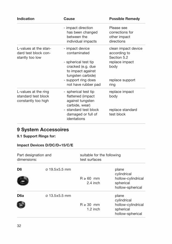
9 System Accessoires9.1 Support Rings for:
lmpact Devices D/DC/D+15/C/E
Part designation and suitable for the followingdimensions: test surfaces
D6 Ø 19.5x5.5 mm planecylindrical
R ≥ 60 mm hollow-cylindrical2.4 inch spherical
hollow-spherical
D6a Ø 13.5x5.5 mm planecylindrical
R ≥ 30 mm hollow-cylindrical1.2 inch spherical
hollow-spherical
32
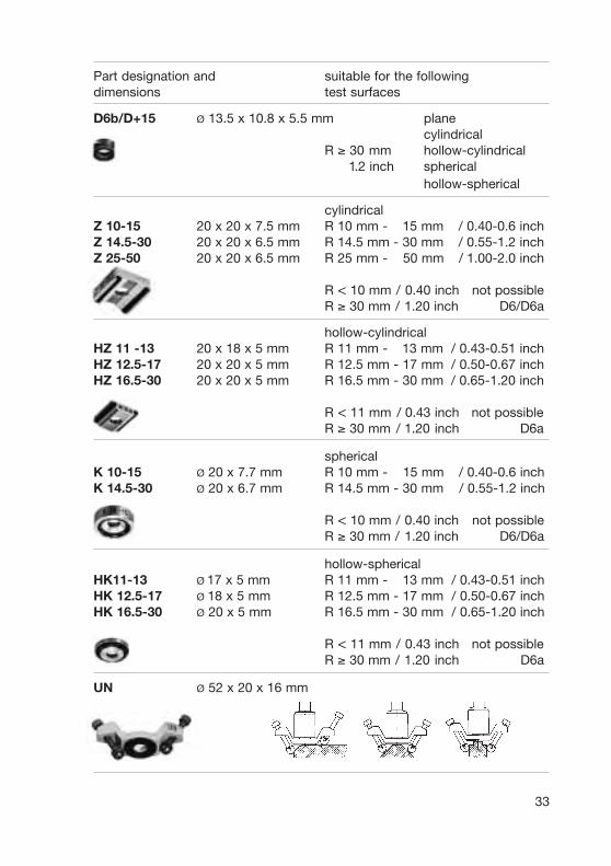
Part designation and suitable for the followingdimensions test surfaces
D6b/D+15 Ø 13.5 x 10.8 x 5.5 mm planecylindrical
R ≥ 30 mm hollow-cylindrical1.2 inch spherical
hollow-spherical
cylindricalZ 10-15 20 x 20 x 7.5 mm R 10 mm - 15 mm / 0.40-0.6 inchZ 14.5-30 20 x 20 x 6.5 mm R 14.5 mm - 30 mm / 0.55-1.2 inchZ 25-50 20 x 20 x 6.5 mm R 25 mm - 50 mm / 1.00-2.0 inch
R < 10 mm / 0.40 inch / not possibleR ≥ 30 mm / 1.20 inch / D6/D6a
hollow-cylindricalHZ 11 -13 20 x 18 x 5 mm R 11 mm - 13 mm / 0.43-0.51 inchHZ 12.5-17 20 x 20 x 5 mm R 12.5 mm - 17 mm / 0.50-0.67 inchHZ 16.5-30 20 x 20 x 5 mm R 16.5 mm - 30 mm / 0.65-1.20 inch
R < 11 mm / 0.43 inch / not possibleR ≥ 30 mm / 1.20 inch / D6a
sphericalK 10-15 Ø 20 x 7.7 mm R 10 mm - 15 mm / 0.40-0.6 inchK 14.5-30 Ø 20 x 6.7 mm R 14.5 mm - 30 mm / 0.55-1.2 inch
R < 10 mm / 0.40 inch / not possibleR ≥ 30 mm / 1.20 inch / D6/D6a
hollow-sphericalHK11-13 Ø 17 x 5 mm R 11 mm - 13 mm / 0.43-0.51 inchHK 12.5-17 Ø 18 x 5 mm R 12.5 mm - 17 mm / 0.50-0.67 inchHK 16.5-30 Ø 20 x 5 mm R 16.5 mm - 30 mm / 0.65-1.20 inch
R < 11 mm / 0.43 inch / not possibleR ≥ 30 mm / 1.20 inch / D6a
UN Ø 52 x 20 x 16 mm
33

34
9.2 Automatic Hardness Tester EQUOmatic 2
The core of EQUOmatic 2 withthe impact device type E, (syn-thetic diamond test tip).The automatic hardness tester isdesigned as a compact, electro-mechanically driven integrablecomponent suitable for installa-tion in production or inspectionlines.See leafet 2002 08 387 E
The EQUOSTAT hardness testeris based on the static measuringprinciple Rockwell HRZ and isspecially designed for hardnessmeasurements on small test ob-jects.Typical applications are thin orthinly coated parts, sheet metals,pins, tubes and cylindrical speci-mens.See leaflet 2001 10 503 E
9.3 Hardness Tester EQUOSTAT
Impact Device G
Part designation and suitable for the followingdimensions: test surfaces
G6 Ø 29.5 x 7 mm platecylindrical
R ≥100 mm hollow-cylindrical4 inch spherical
hollow-spherical
G6a Ø 19.5 x 7 mm platecylindrical
R ≥ 50 mm hollow-cylindrical2 inch spherical
hollow-spherical

Appendices for impact device S
NoteThe Following appendices refer to impact device S. The same conditions as for impact device D apply unless special appendices follow.
• Impact device S is also available as unit S.•DeliverywithstandardtestblockS(alsoavailablewithMPA-certificate)• Test block D labeled with LS-values• The testing ball is made of special material with 10 times better durability compared to the testing ball of impact device D.• Max. hardness of sample 970 HV.• Lenght of impact device 155 mm.
Measuring rangeGroup of material Hartness test-method Impact device S1 Steel and cast steel Vickers HV 101-964
Brinell HB 101-640Tensile strenght N/mm² σ1
σ2
σ3
Rockwell HRC 22-70 HRB HRA 61-88Shore HS 28-104
2 Cold work tool steel Vikers HV 104-924Rockwell HRC 21-68
3 Stainless steel and hightemperature resistant steel
Vickers HV 119-934Brinell HB 105-656Rockwell HRC 21-64 HRB 70-104
6 Cast aluminium alloys Brinell HB 20-184Vickers HV 22-196