Embed Size (px)
Citation preview

www.hardinge.com
WORKHOLDING
HARDINGESure Grip®
3-Jaw Power Chucks

The Hardinge Advantage
Workholding Design Expertise.Hardinge is committed to being your single source for all of your workholding and industrial products for your material-cutting needs. Well known for high accuracy and precision, Hardinge manufactures collets, step chucks, toolholders, CNC tooling, collet chucks, 3-jaw power chucks and chuck jaws.
Hardinge designed the Sure-Grip® 3-Jaw Power Chuck using Finite Element Analysis (FEA) to assure a quality product. Hardinge chucks are lever- operated, counter-centrifugal and dynamically balanced to maintain jaw force. This chuck design is superior to a non-counterbalanced, wedge-style chuck that could be slowing down your removal rates. Read about the Sure-Grip benefits over the next few pages. Hardinge 3-Jaw Power Chucks and Quick-Change Chucks are adaptable to all brands of CNC lathes and are competitively priced.
For additional technical information or to place your order call 800-843-8801, fax 607-734-3886 or visit www.hardingetooling.com. Pricing and availability is online at your fingertips, where it’s fast and easy to place your order.
www.hardingetooling.com
LeverMaster Jaw
Counter Weight
Top Jaw
Pivot
DRAW
FOR
CE
F
F
F
D
• Lever-operated
• Counter-balanced with counter weight to take advantage of centifugal force
• TIR accuracy of .0005"
• Repeatability of .0005"
• Mechanical advantage over wedge-style chucks
Cover Photo: Hardinge 8" Sure-Grip Power Chuck mounted in the Hardinge GS 200 turning center.

Sure-Grip® 3-Jaw Power Chucks
Lever-Operated and Fully BalancedAll Sure-Grip Power Chucks are lever-operated, counter-centrifugal and dynam-ically balanced. This enables you to continually operate your CNC lathe at higher spindle speeds and feed rates with less concern for loss of jaw force normally associated with other manufacturer’s chucks.
Direct MountSure-Grip Power Chucks mount directly to all ANSI A2-4, A2-5, A2-6 and A2-8 spindles, eliminating the added tolerance buildup when using special adapter plates.
Large Thru-HoleSure-Grip Power Chucks have a large thru-hole capacity to help reduce bar stock restrictions that may be common to other power chucks. Refer to the chuck specification charts on the following pages.
Optimum Gripping ForceUnlike conventional chucks that are not counterbalanced, the Sure-Grip Jaw Chuck with its counterbalance feature helps maintain optimum gripping force at high RPM as shown on these calculated gripping charts shown at the right.
4000
8000
12000
16000
20000
24000
28000
32000
3500300025002000150010005000
Spindle Speed (RPM)
Tota
l Gri
pp
ing
Fo
rce
(Lb
s.)
0
12" Power Chuck
10" Power Chuck
0
4000
8000
12000
16000
20000
24000
28000
32000
450040003500300025002000150010005000
Spindle Speed (RPM)
Tota
l Gri
pp
ing
Fo
rce
(Lb
s.)
4" Power Chuck
0
1000
2000
3000
4000
5000
6000
7000
8000
8000
7500
7000
6500
6000
5500
5000
4500
4000
3500
3000
2500
2000
1500
1000
5000
Spindle Speed (RPM)
Tota
l Gri
pp
ing
Fo
rce
(Lb
s.)
8" Power Chuck
0
2000
4000
6000
8000
10000
12000
14000
16000
18000
55005000450040003500300025002000150010005000
Spindle Speed (RPM)
Tota
l Gri
pp
ing
Fo
rce
(Lb
s.)
5" & 6" Power Chuck
0
2000
4000
6000
8000
10000
12000
14000
7000
6500
6000
5500
5000
4500
4000
3500
3000
2500
2000
1500
100050
00
5" Chuck
6" Chuck
Spindle Speed (RPM)
Tota
l Gri
pp
ing
Fo
rce
(Lb
s.)
Hardinge Grip Force Charts
Sure-Grip® 3-Jaw Power Chucks
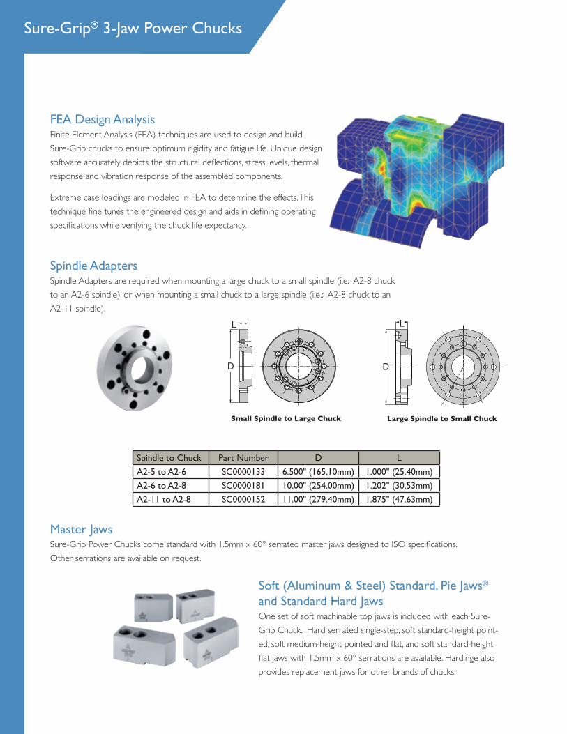
FEA Design AnalysisFinite Element Analysis (FEA) techniques are used to design and build Sure-Grip chucks to ensure optimum rigidity and fatigue life. Unique design software accurately depicts the structural deflections, stress levels, thermal response and vibration response of the assembled components.
Extreme case loadings are modeled in FEA to determine the effects. This technique fine tunes the engineered design and aids in defining operating specifications while verifying the chuck life expectancy.
Master JawsSure-Grip Power Chucks come standard with 1.5mm x 60° serrated master jaws designed to ISO specifications. Other serrations are available on request.
Small Spindle to Large Chuck Large Spindle to Small Chuck
Spindle AdaptersSpindle Adapters are required when mounting a large chuck to a small spindle (i.e: A2-8 chuck to an A2-6 spindle), or when mounting a small chuck to a large spindle (i.e.: A2-8 chuck to an A2-11 spindle).
Soft (Aluminum & Steel) Standard, Pie Jaws® and Standard Hard JawsOne set of soft machinable top jaws is included with each Sure-Grip Chuck. Hard serrated single-step, soft standard-height point-ed, soft medium-height pointed and flat, and soft standard-height flat jaws with 1.5mm x 60° serrations are available. Hardinge also provides replacement jaws for other brands of chucks.
L
D
L
D
Spindle to Chuck Part Number D L
A2-5 to A2-6 SC0000133 6.500" (165.10mm) 1.000" (25.40mm)
A2-6 to A2-8 SC0000181 10.00" (254.00mm) 1.202" (30.53mm)
A2-11 to A2-8 SC0000152 11.00" (279.40mm) 1.875" (47.63mm)

4" & 5" Sure-Grip Power Chucks
5" CHUCK SPECIFICATIONS Spindle Nose A2-5Item Size (in/mm) 5/125Model Number HM-305Part Number SCA2000305A25HBlank Link Part Number —Serrations 1.5mm x 60°Thru-Hole (in/mm) 1.668/42.00Jaw Stroke Diameter (in/mm) .194/4.92Plunger Stroke (in/mm) .413/10.50Maximum Draw Bar Pull (lb/N) 3,300/14,700Maximum Gripping Force (lb/N) 9,000/40,000Maximum RPM 7,000Approximate Weight (lb/kg) 17.00/7.70Moment of Inertia (lb-ft-sec2/kg-m2) .017/.023Max. Rec. Chucking Diameter (in/mm) 4.5/114.00Accuracy—TIR (in/mm) .0005/.0127Repeatability (in/mm) .0005/.0127Dynamic Balance G - 6.3Optional Balance G - 2.5
5" CHUCK DIMENSIONS (in/mm) Spindle Nose A2-5B (Bolt Thread) 7/16 x 14/M10 x 1.5D (Diameter) 5.500/140.00E .787/20.00H (Thru-Hole) 1.668/42.00K —L (Length) 3.198/81.22L1 Minimum 3.765/96.63L1 Maximum 4.178/106.12T (Thread) 1.87" x 1.75mmW 1.000/25.40X Start (External Gripping) 1.643/41.73
5" Chuck for Hardinge CNC Lathes:
4" CHUCK SPECIFICATIONS Spindle Nose A2-4Item Size (in/mm) 4/100Model Number HM-304Part Number SCA2000304A24HSerrations 1.5mm x 60°Thru-Hole (in/mm) 1.078/27.38Jaw Stroke Diameter (in/mm) .186/4.72Plunger Stroke (in/mm) .375/9.52Maximum Draw Bar Pull (lb/N) 3,300/14,700Maximum Gripping Force (lb/N) 8,400/37,360Maximum RPM 8,000Approximate Weight (lb/kg) 13.50/6.10Moment of Inertia (lb-ft-sec2/kg-m2) .009/.012Max. Rec. Chucking Diameter (in/mm) 3.800/96.52Accuracy—TIR (in/mm) .0005/.0127Repeatability (in/mm) .0005/.0127Dynamic Balance G - 6.3Optional Balance G - 2.5
4" CHUCK DIMENSIONS (in/mm) Spindle Nose A2-4B (Bolt Thread) 7/16 x 14/M10 x 1.5D (Diameter) 4.881/124.00E .551/14.00H (Thru-Hole) 1.078/27.38L (Length) 3.187/80.94L1 Minimum 2.960/75.18L1 Maximum 3.340/84.83T (Thread) 1.238 x 20mmW 1.000/25.40X Start (External Gripping) 1.424/36.16
4" Chuck for Hardinge CNC Lathe:
for all Horizontal CNC Lathes

6" Chucks 8" Chucks 10" Chucks 12" ChucksBIG-BORE CHUCK for Other Brands for Other Brands for Other Brands for Other BrandsSPECIFICATIONS of CNC Lathes of CNC Lathes of CNC Lathes of CNC LathesSpindle Nose A2-5 A2-6 A2-8 A2-8Item Size (in/mm) 6/150 8/200 10/250 12/300Model Number CM2-306C-5 CM2-308C-6 CM2-310C-8 CM2-312C-8Part Number SCA-2300306-A25C SC-2300308-A26C SCA-2300310-A28C SCA-2300312-A28CBlank Link Part Number SC-0000339 SC-0000522 SC-0000553 SC-0000419Serrations 1.5mm x 60° 1.5mm x 60° 1.5mm x 60° 1.5mm x 60°Thru-Hole (in/mm) 2.050/52.00 2.696/68.47 3.616/91.84 3.800/96.52Jaw Stroke Diameter (in/mm) .220/5.58 .312/7.90 .374/9.49 .420/10.66Plunger Stroke (in/mm) .498/12.60 .565/14.30 .800/20.32 .895/22.70Maximum Draw Bar Pull (lb/N) 4,500/20,000 7,000/31,000 11,000/48,930 12,000/53,000Maximum Gripping Force (lb/N) 13,000/58,000 19,000/84,500 31,500/140,110 32,000/142,000Maximum RPM 7,000 5,000 4,200 3,500Approximate Weight (lb/kg) 27.30/12.40 54.00/24.40 89.00/40.50 127.00/57.60Moment of Inertia (lb-ft-sec2/kg-m2) .035/.047 .120/.150 .250/.330 .470/.640Max. Rec. Chucking Diameter (in/mm) 5.50/139.00 8.00/203.00 9.50/241.00 11.000/279.40Accuracy—TIR (in/mm) .0005/.0127 .0005/.0127 .0008/.0203 .0010/.0254Repeatability (in/mm) .0005/.0127 .0005/.0127 .0005/.0127 .0008/.0200Dynamic Balance G - 6.3 G - 6.3 G - 6.3 — Optional Balance G - 2.5 G - 2.5 G - 2.5 —
BIG-BORE CHUCK DIMENSIONS (in/mm) Spindle Nose A2-5 A2-6 A2-8 A2-8B (Bolt Thread) 7/16 x 14/M10 x 1.5 1/2 x 13/M12 x 1.75 5/8 x 11/M16 x 2 5/8 x 11/M16 x 2D (Diameter) 6.650/169.00 8.960/227.50 10.5/266 12/300E .787/20.00 .984/25.00 1.181/30.14 1.181/30.00H (Thru-Hole) 2.050/52.00 2.696/68.48 3.616/91.84 3.800/96.52K 1.000/25.40 1.194/30.32 1.000/25.40 .960/24.40L (Length) 3.678/93.42 4.120/104.65 5.025/127.63 5.440/138.00L1 Minimum .520/13.20 .710/18.03 .740/18.79 .780/19.80L1 Maximum 1.000/25.40 1.263/32.08 1.520/38.60 1.670/42.40W 1.250/32.00 1.500/38.00 1.750/44.45 2.000/50.80X Start (External Gripping) 2.127/54.00 2.700/68.50 3.440/87.37 3.420/86.87
6" Chuck for Other Brands of CNC Lathes: 8" Chuck for Other Brands of CNC Lathes:
10" Chuck for Other Brands of CNC Lathes: 12" Chuck for Other Brands of CNC Lathes:
These Big-Bore chucks can be mounted with Quick-Change Sure-Grip Top Jaws!See page 21 for corresponding Quick-Change Top Jaws and Conversion Kit Numbers.
for all Horizontal CNC Lathes
Ref.
B
L
D H
K
LRef.
1
E
X
W
BL
D H
K
LRef.
1
E
X
W
Special Wrenchused with all
Chucks this page.
Big-Bore Power Chucks

Jaws – Style P
G
W
H
B
SSL
Made with 1018 Cold-Rolled Steel (can be carborized and hardened by customer)SPECIFICATIONS (inches—unless specified otherwise) Chuck Size Model Part W H L G S B Weight (lb) Number Number (Width) (Height) (Length) (Groove) (Spacing) (Bolt) Set of 3 4" 4MSHF* SC-2000225S 1.00 1.12 1.95 .394 .551 8mm 1.50 4MMHF* SC-2000226S 1.00 1.50 1.95 .394 .551 8mm 2.10 4MSHP SC-2000222S 1.00 1.12 2.22 .394 .551 8mm 1.44 4MMHP SC-2000227S 1.00 1.50 2.22 .394 .551 8mm 1.50 4MH1 SC-2000224S 1.00 1.12 2.06 .394 .551 8mm 1.50 5" 5MSHF* SC-2000070S 1.00 1.12 2.40 .395 .709 8mm 1.50 5MMHF* SC-2000071S 1.00 1.49 2.48 .395 .709 8mm 2.70 5MSHP SC-2000066S 1.00 1.12 2.77 .395 .709 8mm 1.92 5MMHP SC-2000073S 1.00 1.50 2.77 .395 .709 8mm 3.00 5MH1 SC-2000072S 1.00 1.22 2.42 .395 .708 8mm 1.50 6" 6MSHF* SC-2000019S 1.25 1.25 2.75 .473 .787 10mm 3.00 6MMHF* SC-2000020S 1.25 1.75 2.75 .473 .787 10mm 4.20 6MSHP SC-2000016S 1.25 1.25 3.09 .473 .787 10mm 2.94 6MMHP SC-2000023S 1.25 1.75 3.09 .473 .787 10mm 1.30 6MH1 SC-2000021S 1.25 1.42 2.83 .473 .787 10mm 2.25 8" 8MSHF* SC-2000119S 1.50 1.50 3.36 .551 .984 12mm 5.25 8MMHF* SC-2000120S 1.50 2.00 3.36 .551 .984 12mm 7.20 8MSHP SC-2000603S 1.50 1.493 4.062 .551 .984 12mm 5.40 8MSHPL SC-2000603S 1.50 1.483 4.062 551 .984 12mm 6.00 8MMHP SC-2000123S 1.50 2.00 3.76 .551 .984 12mm 7.50 8MH1 SC-2000121S 1.50 1.75 2.64 .551 .810 12mm 3.75 10" 10MSHF* SC-2000169S 1.75 1.75 4.00 .631 1.187 12mm 9.00 10MMHF* SC-2000170S 1.75 2.25 4.00 .631 1.187 12mm 11.40 10MSHP SC-2000166S 1.75 1.75 4.56 .631 1.187 12mm 9.30 10MHP SC-2000599S 1.75 2.63 4.56 .631 1.187 12mm 14.00 10MMHP SC-2000173S 1.75 2.25 4.56 .631 1.187 12mm 12.00 10MH1 SC-2000171S 1.75 2.02 4.32 .631 1.187 12mm 6.45 12" 12MSHF* SC-2000426S 2.00 1.972 4.500 .828 1.181 16mm 12.00 12MMHF* SC-2000427S 2.00 2.750 4.500 .828 1.181 16mm 17.40 12MSHP SC-2000416S 2.00 1.972 5.043 .828 1.181 16mm 13.05 12MMHP SC-2000423S 2.00 1.972 5.043 .828 1.181 16mm 18.00 12MH1 SC-2000421S 2.00 2.180 4.927 .828 1.181 16mm 9.00
Flat Nose:
PointedNose:
Made with 6061 T-6 Condition AluminumSPECIFICATIONS (inches—unless specified otherwise) Chuck Size Model Part W H L G S B Weight (lb) Number Number (Width) (Height) (Length) (Groove) (Spacing) (Bolt) Set of 3 5" HAR5MSHA SC-2001163A 1.00 1.25 2.770 .395 .709 8mm 1.00 6" HAR6MSHA SC-2001171A 1.25 1.50 3.090 .474 .787 10mm 1.70 8" HAR8MSHA SC-2001178A 1.50 2.00 3.760 .551 .985 12mm 3.30 10" HAR10MSHA SC-2001188A 1.75 2.00 4.569 .630 1.181 12mm 4.70
Aluminum Jaws – 1.5mm x 60° – Fine Metric Serrations
Bottom clearedfor stop plate
4MH1, 5MH1, 6MH1, 8MH1, 10MH1 & 12MH1models are hardenedsingle-step jaws:
G
W
H
1/8" Flat
30°
BS
L
Note: See Style "Q" for corresponding Pie Jaws® *Flat nose
Steel Jaws – 1.5mm x 60° – Fine Metric Serrations
Made with 1018 Cold-Rolled Steel (can be carborized and hardened by customer)SPECIFICATIONS (inches—unless specified otherwise) Chuck Size Model Part W H L G S B Flat Number Number (Width) (Height) (Length) (Groove) (Spacing) (Bolt) (Width) 6" HKT6-125 SC-2000001SK6 1.25 1.25 3.00 .474 .787 .69 .1301 HKT6-200 SC-2000002SK6 1.25 2.00 3.00 ,474 ,787 .69 .130 8" HKT8-150 SC-2000003SK8 1.50 1.50 3.75 .551 .985 .78 .125 HKT8-300 SC-2000004SK8 1.50 3.00 3.75 .551 .985 .78 .125 10" HKT10-200 SC-2000005SK10 1.75 2.00 4.50 .630 1.181 .78 .130 HKT10-300 SC-2000006SK10 1.75 3.00 4.50 .630 1.181 .78 .130
Jaws are compatible with Hardinge, Kitagawa, Logansport Matsumoto and Howa Chucks.
W
G
LS
H
30°
Flat
Steel Jaws – 1.5mm x 60° – Fine Metric Serrations
Aluminum, Steel and Soft

Pie Jaws – Style Q
GD
H
1/4" Gap
B
60° x 1.5mmSerrations
S
N
SPECIFICATIONS (inches unless specified otherwise) Chuck Size Model Part D H G S B N Weight (lb) Number Number (Diameter) (Height) (Groove) (Spacing) (Bolt) Set of 3 5" HAR5MSHP SC-2001379A 6.00 2.00 .395 .709 8mm 1.687 7.50 HAR5MSHP1 SC-2001380A 6.00 4.00 .395 .709 8mm 1.687 10.00 6" HAR6MSHP SC-2001388A 6.50 2.00 .474 .787 10mm 1.937 9.00 HAR6MSHP1 SC-2001389A 6.50 4.00 .474 .787 10mm 1.937 11.50 8" HARMSHP SC-2001399A 8.00 2.00 .551 .985 12mm 2.265 9.50 HAR8MSP1 SC-2001400A 8.00 4.00 .551 .985 12mm 2.265 19.00 10" HAR10MSHP SC-2001413A 10.00 2.00 .630 1.181 12mm 2.750 15.00 HAR10MSHP1 SC-2001414A 10.00 4.00 .630 1.181 12mm 2.750 30.00 12" KTT-B212-P-A 3 SC-2001424A 12.00 2.50 .828 1.181 16mm 2.687 28.00 KTTB212-P-1-A 3 SC-2001425A 12.00 5.00 .828 1.181 16mm 2.687 51.00
Note: See Style "P" for corresponding straight aluminum or steel jaws. When using oversized jaws, maximum RPM must be reduced - consult
your chuck manual. 3 3 holes in jaw – Do not overhang Pie Jaw OD past chuck OD
Aluminum Pie Jaws – Style Q1.5mm x 60° Fine Metric Serrations
Hardinge K- and Q-style Pie Jaws are made from A319cast aluminum to allow fast machining at high rpm.
Steel and cast iron jaws are also available.
Aluminum

6" – $550.00 8" – $650.0010" – $700.0012" – $775.00
Quick-Change Sure-Grip® Kits
• Revolutionary Quick-Change top jaw design (patented)
• Each top jaw changes with the simple turn of a single locking bolt in less than one minute (much faster than conven-tional jaws)
• Lever-operated for high grip force
• Hardinge-designed safety feature utilizes centrifugal force and a unique locking system, eliminating the possibility of the quick-change jaws coming off during operation
• Counter-centrifugal design provides for least grip force loss
• 6", 8", 10" and 12" direct-mount chucks
• Larger machineable jaw area allows a greater variety of workpieces to be held than with conventional chucks
• Master jaw serrations 1.5mm x 60°
• No special tools required• Will accept standard jaws
Quick-Change Conversion Kits for standard Sure-Grip® Power ChucksConvert your standard Hardinge Sure-Grip power chuck into a quick-change style chuck for faster jaw changeover. Kit includes conversion kit with top jaws.
KIT CONFIGURATIONS Chuck Size Sure-Grip Chuck Spindle Top Jaw Conversion Kit Model Number Nose Model No. Assembly No. CM2-306C-5 A2-5 6MQP2 SC-2000747QC 6" HM-306 A2-5 6MQP1 SC-2000741QC HM-306-6 A2-6 6MQP3 SC-2000746QC HM-306-6L A2-6 6MQP3 SC-2000746QC HM-308-5 A2-5 8MQP1 SC-2000721QC 8" CM2-308B-6 A2-6 8MQP1 SC-2000721QC CM2-308C-6 A2-6 8MQP2 SC-2000727QC HM-308 A2-6 8MQP1 SC-2000721QC HM-310-6 A2-6 10MQP1 SC-2000701QC CM2-310B-8 A2-8 10MQP1 SC-2000701QC 10" CM2-310C-8 A2-8 10MQP2 SC-2000706QC HM-310-8 A2-8 10MQP1 SC-2000701QC HVM-310-8 A2-8 10MQP1 SC-2000701QC HVM-310-11 A2-11 10MQP1 SC-2000701QC HCM-312C-8 A2-8 12MQP1 SC-2000761QC 12" HM-312C-8 A2-8 12MQP1 SC-2000761QC HVM312C-8 A2-8 12MQP1 SC-2000761QC HVM-312C-11 A2-11 12MQP1 SC-2000761QCNote: See pages 6-12 for corresponding Hardinge Sure-Grip Chucks

Quick-Change Sure-Grip® Jaws
Made with 1018 Cold-Rolled Steel (can be carborized and hardened by customer)QUICK-CHANGE TOP JAW SPECIFICATIONS (inches unless specified otherwise) Chuck Size Chuck Spindle Top Jaw Top Jaw Length Width Height Serrations C Thread Weight (lb) Model Number Nose Model No. Part Number Set of 3 CM2-306C-5Q A2-5 6MQP2 SC-2000747S 3.15 1.25 1.46 1.5mm x 60° 1.22 M10 x 1.50 3.36 6" HM-306-Q A2-5 6MQP1 SC-2000741S 3.03 1.25 1.46 1.5mm x 60° 1.22 M10 x 1.50 3.36 HM-306-6Q A2-6 6MQP3 SC-2000746S 3.05 1.25 1.46 1.5mm x 60° 1.22 M10 x 1.50 3.36 HM-306-6LQ A2-6 6MQP3 SC-2000746S 3.05 1.25 1.46 1.5mm x 60° 1.22 M10 x 1.50 3.36 HM-308-5Q A2-5 8MQP1 SC-2000721S 3.76 1.50 1.63 1.5mm x 60° 1.68 M10 x 1.50 5.52 8" CM2-308C-6Q A2-6 8MQP2 SC-2000727S 3.76 1.50 1.63 1.5mm x 60° 1.68 M10 x 1.50 5.52 CM2-308B-6Q A2-6 8MQP1 SC-2000721S 3.76 1.50 1.63 1.5mm x 60° 1.68 M10 x 1.50 5.52 HM-308-Q A2-6 8MQP1 SC-2000721S 3.76 1.50 1.63 1.5mm x 60° 1.68 M10 x 1.50 5.52 HM-310-6Q A2-6 10MQP1 SC-2000701S 4.58 1.75 1.72 1.5mm x 60° 2.05 M12 x 1.75 9.48 CM2-310B-8Q A2-8 10MQP1 SC-2000701S 4.58 1.75 1.72 1.5mm x 60° 2.05 M12 x 1.75 9.48 CM2-310C-8Q A2-8 10MQP2 SC-2000706S 4.87 1.75 1.72 1.5mm x 60° 2.05 M12 x 1.75 9.75 10" HM-310-8Q A2-8 10MQP1 SC-2000701S 4.58 1.75 1.72 1.5mm x 60° 2.05 M12 x 1.75 9.48 HVM-310-8Q A2-8 10MQP1 SC-2000701S 4.58 1.75 1.72 1.5mm x 60° 2.05 M12 x 1.75 9.48 HVM-310-11Q A2-11 10MQP1 SC-2000701S 4.58 1.75 1.72 1.5mm x 60° 2.05 M12 x 1.75 9.48 CM2-312C-8Q A2-8 12MQP1 SC-2000761S 5.42 2.00 1.96 1.5mm x 60° 2.55 M16 x 2.00 13.5 12" HM-312C-8Q A2-8 12MQP1 SC-2000761S 5.42 2.00 1.96 1.5mm x 60° 2.55 M16 x 2.00 13.5 HVM-312C-8Q A2-8 12MQP1 SC-2000761S 5.42 2.00 1.96 1.5mm x 60° 2.55 M16 x 2.00 13.5 HVM-312C-11Q A2-11 12MQP1 SC-2000761S 5.42 2.00 1.96 1.5mm x 60° 2.55 M16 x 2.00 13.5Note: See pages 13-17 for corresponding Hardinge Quick-Change Sure-Grip Chucks
Quick-Change Steel Jaws – 1.5mm x 60°Fine Metric Serrations
L
SPECIFICATIONS (inches unless specified otherwise) Chuck Size Spindle Part L H W K E S B Nose Number (Length) (Height) (Width) (Spacing) (Bolt) 4" A2-4 SC-0000223 1.136 .705 .553 .393 .219 .551 M8 x 1.25 5" A2-5 SC-0000065 .620 .705 .553 .393 .219 N/A M8 x 1.25 (*two parts required) SC-0000067 .595 .705 .553 .393 .219 N/A M8 x 1.25 6" A2-5 SC-0000015 1.570 .719 .646 .470 .250 .787 M10 x 1.50 6" A2-6 SC-0000500 1.507 .719 .646 .470 .250 .787 M10 x 1.50 8" A2-5 & A2-6 SC-0000115 .650 .976 .750 .548 .313 N/A M12 x 1.75 (*two parts required) SC-0000131 .700 .796 .750 .548 .313 N/A M12 x 1.75 10" A2-6, A2-8,A2-11 SC-0000165 2.227 .976 .923 .631 .390 1.187 M12 x 1.75 12" A2-8 & A2-11 SC-0000412 2.470 1.047 1.170 .825 .443 1.181 M16 x 2.00
Bolt SizeK
W
LSH
E
I-BEAM ASSEMBLIESfor Hardinge Quick-Change
Chuck Jaws
Chuck Size Part Number 6" (A2-5) SC-0000740QC 6.5" (A2-6) SC-0000745QC 8" SC-0000720QC 10" SC-0000700QC 10.5" SC-0000700QC 12" SC-0000760QC
Jaw Nuts (T-Nuts)1.5mm x 60°Serrated Jaws
Jaws for All Chuck BrandsHardinge® is your source for replacement Jaws for all brands of chucks manufactured worldwide. • Steel and aluminum jaws for American Standard tongue and groove• Metric tongue and groove• Woodworth dovetail tongue and groove• American Standard square serrated key • Acme serrated cross key• 1⁄16" x 90° serrated• 1⁄32" x 90° serrated• 1.5mm x 60° serrated• 3.0mm x 60° serrated • Pie Jaws®– aluminum and steel• Master plates and segments from 10" to 60" diameters
I-Beam Assembliesfor 1.5mm x 60°Serrated Jaws

Drawbar Information
Request for Machine Spindle and Drawbar Information
Drawbar Linkups are required for mounting Hardinge Chucks and Collet Adaptation Chucks including the FlexC™ Collet System to CNC lathes. Fill in the requested information and dimensions corresponding to the illustration if you would like Hardinge to machine the drawbar linkup for your specific application. You may contact Hardinge for a preliminary quote prior to filling out this form at 800-843-8801.
Company
Contact Name
Address
City, State, Zip
Phone
Fax
Machine Manufacturer
Machine Model
Actuator Manufacturer
FlexC™ System Part Number
A. Spindle Configuration A2-5 A2-6 A2-8
or other ________________________________
B. Draw Tube / Bar Thread Left-hand or Right-hand Internal or External Thread
C. Length of Thread
_____________________________
D/E. Distance from front of spindle to front of draw
tube / bar when forward and retracted. (Indicate positive {+} if the draw tube / bar is in front of the spindle face, or negative {-} if behind the spindle face)
D. Retracted (back) __________________________
E. Forward _________________________________
Z. Turret Face when closest to Spindle ____________
Email this form to [email protected] or fax to Hardinge Customer Service at 607.734.3886 www.hardinge.com • www.ShopHardinge.com • p. 800.843.8801
All specifications subject to change without notice.
All marks indicated by ® and ™ are trademarks of their
respective owners. #2357C • Litho in USA • ©Hardinge Inc.
• October 2014
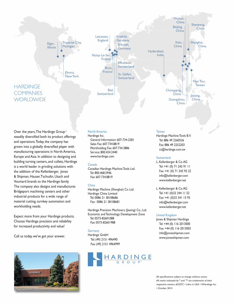
Over the years, The Hardinge Group™ steadily diversified both its product offerings and operations. Today, the company has grown into a globally diversified player with manufacturing operations in North America, Europe and Asia. In addition to designing and building turning centers, and collets, Hardinge is a world leader in grinding solutions with the addition of the Kellenberger, Jones & Shipman, Hauser, Tschudin, Usach and Voumard brands to the Hardinge family. The company also designs and manufactures Bridgeport machining centers and other industrial products for a wide range of material cutting, turnkey automation and workholding needs.
Expect more from your Hardinge products. Choose Hardinge precision and reliability for increased productivity and value!
Call us today, we’ve got your answer.
HARDINGECOMPANIESWORLDWIDE
North AmericaHardinge Inc. General Information: 607-734-2281 Sales Fax: 607.734.8819 Workholding Fax: 607.734.3886 Service: 800.424.2440 www.hardinge.com
Canada Canadian Hardinge Machine Tools Ltd. Tel: 800.468.5946 Fax: 607.734.8819
China Hardinge Machine (Shanghai) Co. Ltd.Hardinge China Limited Tel: 0086 21 38108686 Fax: 0086 21 38108681
Hardinge Precision Machinery (Jiaxing) Co., Ltd.Economic and Technology Development Zone Tel: 0573-82601088 Fax: 0573-82601988
Germany Hardinge GmbH Tel: (49) 2151 496490 Fax: (49) 2151 4964999
Taiwan Hardinge Machine Tools B.V. Tel: 886 49 2260536 Fax: 886 49 2252203 [email protected]
Switzerland L. Kellenberger & Co. AG Tel: +41 (0) 71 242 91 11 Fax: +41 (0) 71 242 92 22 [email protected] www.kellenberger.net
L. Kellenberger & Co. AG Tel: +41 (0)32 344 11 52 Fax: +41 (0)32 341 13 93 [email protected] www.kellenberger.net
United KingdomJones & Shipman Hardinge Tel: +44 (0) 116 2013000 Fax: +44 (0) 116 2013002 [email protected] www.jonesshipman.com