Embed Size (px)
Citation preview
HTR
GPB
GGP
4xT
H
G
CFP
RM
EF
RM
FP
A
CU
CV
(1)
X
Y
D
ZDIN
332
"D"
XA
YA
DA
ZA
DIN
332
"D"
D
GS
GS
6xTS
L
LA
FS
K
CA
FTFU
DA
J
JA
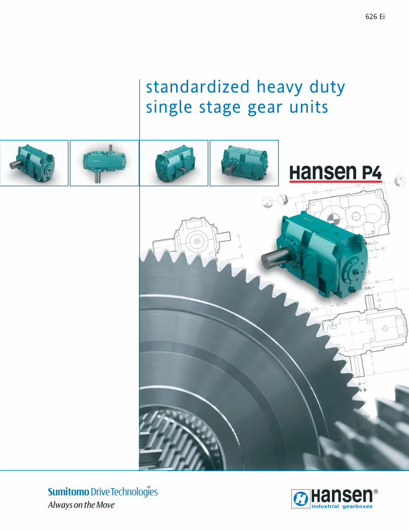
626 Ei
standardized heavy duty single stage gear units
See our worldwidesales & service network at
www.hansenindustrialgearboxes.com
DO
C-C
AI6
26E/
0713
Hansen Industrial Transmissions nvLeonardo da Vincilaan 1B-2650 Edegem - BelgiumT. +32(0)3 450 12 11F. +32(0)3 450 12 20E. [email protected]
www.hansenindustrialgearboxes.com
Hansen Industrial Transmissions nv commits
to be a pioneering innovator.
The production of high performance
gear units stems from an interactive
partnership with our clients, the end users
and the actively engaged manpower of
our global enterprise. Embracing design,
manufacturing and customer services,
Hansen Industrial Transmissions has grown into
a world leader in its field.
Today, we set standards for both product
and working environment, inciting a
knowing environment to seize all new
and inspiring technologies.
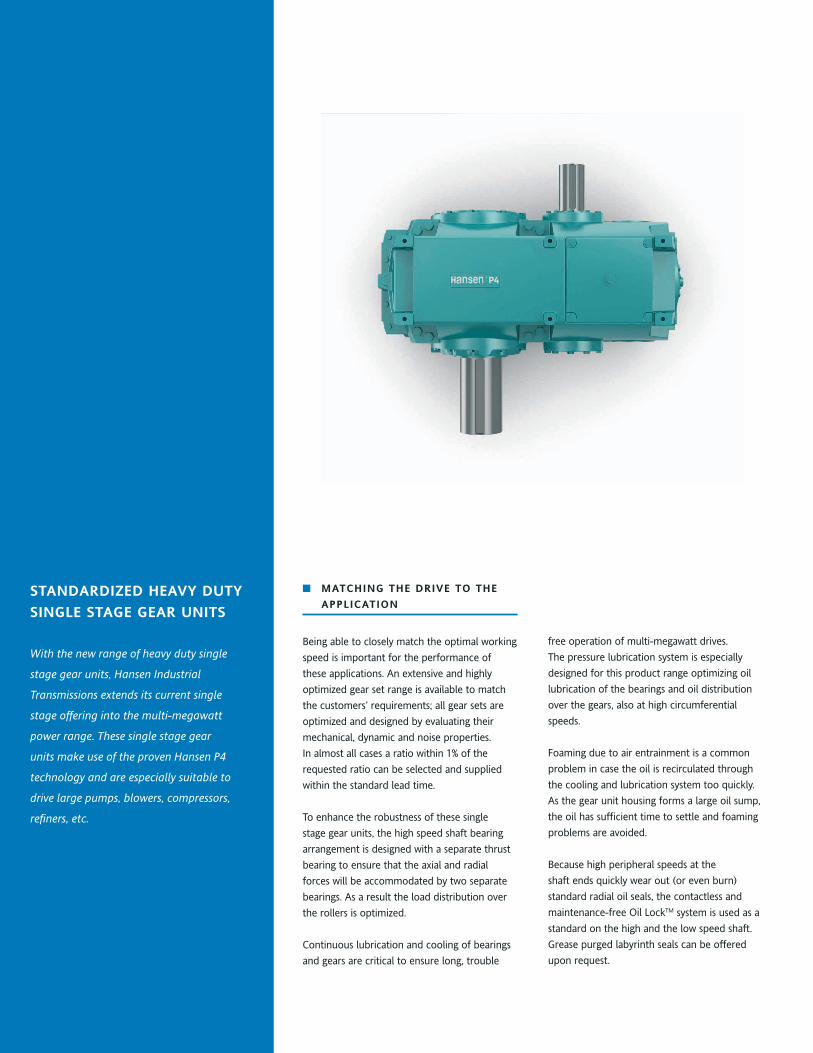
With the new range of heavy duty single
stage gear units, Hansen Industrial
Transmissions extends its current single
stage offering into the multi-megawatt
power range. These single stage gear
units make use of the proven Hansen P4
technology and are especially suitable to
drive large pumps, blowers, compressors,
refiners, etc.
Standardized heavy duty
Single Stage gear unitS
■ MatChing the drive tO the
aPPliCatiOn
Being able to closely match the optimal working
speed is important for the performance of
these applications. An extensive and highly
optimized gear set range is available to match
the customers’ requirements; all gear sets are
optimized and designed by evaluating their
mechanical, dynamic and noise properties.
In almost all cases a ratio within 1% of the
requested ratio can be selected and supplied
within the standard lead time.
To enhance the robustness of these single
stage gear units, the high speed shaft bearing
arrangement is designed with a separate thrust
bearing to ensure that the axial and radial
forces will be accommodated by two separate
bearings. As a result the load distribution over
the rollers is optimized.
Continuous lubrication and cooling of bearings
and gears are critical to ensure long, trouble
free operation of multi-megawatt drives.
The pressure lubrication system is especially
designed for this product range optimizing oil
lubrication of the bearings and oil distribution
over the gears, also at high circumferential
speeds.
Foaming due to air entrainment is a common
problem in case the oil is recirculated through
the cooling and lubrication system too quickly.
As the gear unit housing forms a large oil sump,
the oil has sufficient time to settle and foaming
problems are avoided.
Because high peripheral speeds at the
shaft ends quickly wear out (or even burn)
standard radial oil seals, the contactless and
maintenance-free Oil LockTM system is used as a
standard on the high and the low speed shaft.
Grease purged labyrinth seals can be offered
upon request.
l i t e r a t u r e d O w n l O a d S - S e e w w w . h a n S e n i n d u S t r i a l g e a r b O x e S . C O M
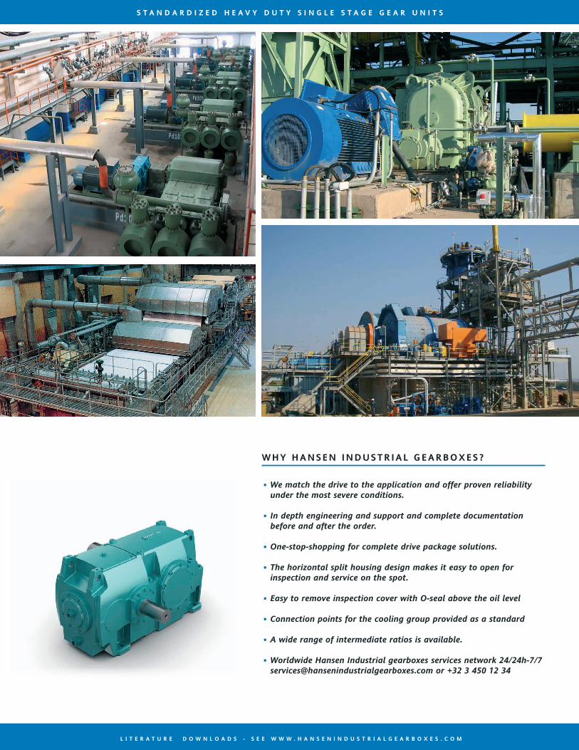
• We match the drive to the application and offer proven reliability under the most severe conditions.
• In depth engineering and support and complete documentation before and after the order.
• One-stop-shopping for complete drive package solutions.
• The horizontal split housing design makes it easy to open for inspection and service on the spot.
• Easy to remove inspection cover with O-seal above the oil level
• Connection points for the cooling group provided as a standard
• A wide range of intermediate ratios is available.
• Worldwide Hansen Industrial gearboxes services network 24/24h-7/7 [email protected] or +32 3 450 12 34
why hanSen induStr ial gearbOxeS?
S t a n d a r d i z e d h e a v y d u t y S i n g l e S t a g e g e a r u n i t S
With the new range of heavy duty single
stage gear units, Hansen Industrial
Transmissions extends its current single
stage offering into the multi-megawatt
power range. These single stage gear
units make use of the proven Hansen P4
technology and are especially suitable to
drive large pumps, blowers, compressors,
refiners, etc.
Standardized heavy duty
Single Stage gear unitS
■ MatChing the drive tO the
aPPliCatiOn
Being able to closely match the optimal working
speed is important for the performance of
these applications. An extensive and highly
optimized gear set range is available to match
the customers’ requirements; all gear sets are
optimized and designed by evaluating their
mechanical, dynamic and noise properties.
In almost all cases a ratio within 1% of the
requested ratio can be selected and supplied
within the standard lead time.
To enhance the robustness of these single
stage gear units, the high speed shaft bearing
arrangement is designed with a separate thrust
bearing to ensure that the axial and radial
forces will be accommodated by two separate
bearings. As a result the load distribution over
the rollers is optimized.
Continuous lubrication and cooling of bearings
and gears are critical to ensure long, trouble
free operation of multi-megawatt drives.
The pressure lubrication system is especially
designed for this product range optimizing oil
lubrication of the bearings and oil distribution
over the gears, also at high circumferential
speeds.
Foaming due to air entrainment is a common
problem in case the oil is recirculated through
the cooling and lubrication system too quickly.
As the gear unit housing forms a large oil sump,
the oil has sufficient time to settle and foaming
problems are avoided.
Because high peripheral speeds at the
shaft ends quickly wear out (or even burn)
standard radial oil seals, the contactless and
maintenance-free Oil LockTM system is used as a
standard on the high and the low speed shaft.
Grease purged labyrinth seals can be offered
upon request.
l i t e r a t u r e d O w n l O a d S - S e e w w w . h a n S e n i n d u S t r i a l g e a r b O x e S . C O M
• We match the drive to the application and offer proven reliability under the most severe conditions.
• In depth engineering and support and complete documentation before and after the order.
• One-stop-shopping for complete drive package solutions.
• The horizontal split housing design makes it easy to open for inspection and service on the spot.
• Easy to remove inspection cover with O-seal above the oil level
• Connection points for the cooling group provided as a standard
• A wide range of intermediate ratios is available.
• Worldwide Hansen Industrial gearboxes services network 24/24h-7/7 [email protected] or +32 3 450 12 34
why hanSen induStr ial gearbOxeS?
S t a n d a r d i z e d h e a v y d u t y S i n g l e S t a g e g e a r u n i t S

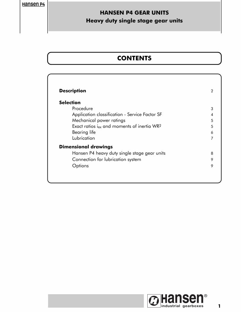
HANSEN P4 GEAR UNITSHeavy duty single stage gear units
1
Description 2
SelectionProcedure 3
Application classification - Service Factor SF 4
Mechanical power ratings 5
Exact ratios iex and moments of inertia WR2 5
Bearing life 6
Lubrication 7
Dimensional drawingsHansen P4 heavy duty single stage gear units 8
Connection for lubrication system 9
Options 9
CONTENTS
DESCRIPTIONHeavy duty single stage gear units
2
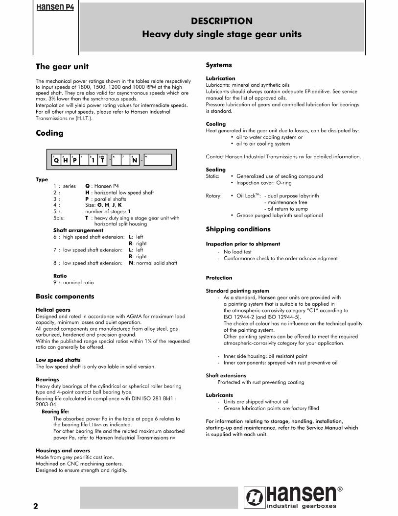
The gear unit
The mechanical power ratings shown in the tables relate respectivelyto input speeds of 1800, 1500, 1200 and 1000 RPM at the highspeed shaft. They are also valid for asynchronous speeds which aremax. 3% lower than the synchronous speeds.Interpolation will yield power rating values for intermediate speeds.For all other input speeds, please refer to Hansen Industrial Transmissions nv (H.I.T.).
Coding
Type1 : series Q : Hansen P42 : H : horizontal low speed shaft3 : P : parallel shafts4 : Size: G, H, J, K5 : number of stages: 15bis: T : heavy duty single stage gear unit with
horizontal split housingShaft arrangement6 : high speed shaft extension: L: left
R: right7 : low speed shaft extension: L: left
R: right8 : low speed shaft extension: N: normal solid shaft
Ratio9 : nominal ratio
Basic components
Helical gearsDesigned and rated in accordance with AGMA for maximum loadcapacity, minimum losses and quiet operation.All geared components are manufactured from alloy steel, gascarburized, hardened and precision ground.Within the published range special ratios within 1% of the requestedratio can generally be offered.
Low speed shaftsThe low speed shaft is only available in solid version.
BearingsHeavy duty bearings of the cylindrical or spherical roller bearingtype and 4-point contact ball bearing type.Bearing life calculated in compliance with DIN ISO 281 Bld1 :2003-04
Bearing life: The absorbed power Pa in the table at page 6 relates to the bearing life L10nm as indicated.For other bearing life and the related maximum absorbed power Pa, refer to Hansen Industrial Transmissions nv.
Housings and coversMade from grey pearlitic cast iron. Machined on CNC machining centers.Designed to ensure strength and rigidity.
Systems
LubricationLubricants: mineral and synthetic oils Lubricants should always contain adequate EP-additive. See servicemanual for the list of approved oils.Pressure lubrication of gears and controlled lubrication for bearingsis standard.
Cooling Heat generated in the gear unit due to losses, can be dissipated by:
• oil to water cooling system or• oil to air cooling system
Contact Hansen Industrial Transmissions nv for detailed information.
SealingStatic: • Generalized use of sealing compound
• Inspection cover: O-ring
Rotary: • Oil LockTM: - dual purpose labyrinth- maintenance free- oil return to sump
• Grease purged labyrinth seal optional
Shipping conditions
Inspection prior to shipment- No load test- Conformance check to the order acknowledgment
Protection
Standard painting system- As a standard, Hansen gear units are provided with
a painting system that is suitable to be applied in the atmospheric-corrosivity category “C1” according to ISO 12944-2 (and ISO 12944-5).The choice of colour has no influence on the technical qualityof the painting system.Other painting systems can be offered to meet the required atmospheric-corrosivity category for your application.
- Inner side housing: oil resistant paint- Inner components: sprayed with rust preventive oil
Shaft extensions Prortected with rust preventing coating
Lubricants- Units are shipped without oil- Grease lubrication points are factory filled
For information relating to storage, handling, installation,starting-up and maintenance, refer to the Service Manual whichis supplied with each unit.
1 2 3 4 5 5bis 6 7 8
-9
Q H P 1 T - N
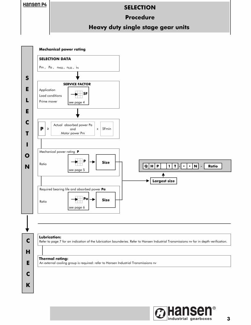
SELECTION
Procedure
Heavy duty single stage gear units
3
Mechanical power rating P
RatioQ H P 1 T - • • N - Ratio
SELECTION DATA
Pm , Pa , nHSS , nLSS , iN
SERVICE FACTOR
Application
Load conditions
Prime mover
PActual absorbed power Pa
andMotor power Pm
x SFmin≥
P Size
S
E
L
E
C
T
I
O
N
C
H
E
C
K
Largest size
Thermal rating: An external cooling group is required: refer to Hansen Industrial Transmissions nv
see page 5
Required bearing life and absorbed power Pa
RatioPa Size
see page 6
SF
see page 4
Mechanical power rating
Lubrication: Refer to page 7 for an indication of the lubrication bounderies. Refer to Hansen Industrial Transmissions nv for in depth verification.
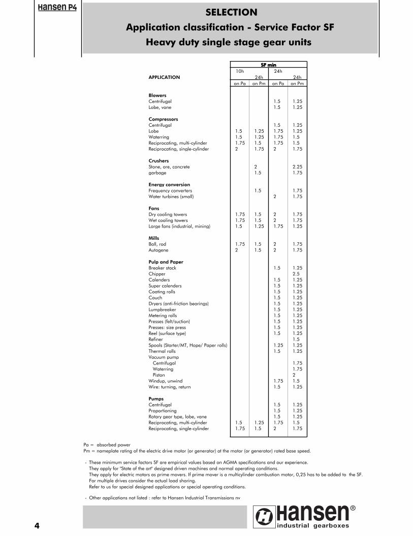
APPLICATION
SSSSFFFF mmmmiiiinnnn10h
24h24h
24h
BlowersCentrifugal
on Pa on Pm on Pa on Pm
1.5 1.25Lobe, vane
CompressorsCentrifugalLobeWaterringReciprocating, multi-cylinderReciprocating, single-cylinder
1.51.5
1.251.25
1.752
1.51.75
1.5 1.25
1.5 1.251.751.75
1.251.5
1.752
1.51.75
CrushersStone, ore, concretegarbage
21.5
Energy conversionFrequency convertersWater turbines (small)
1.5
2.251.75
21.751.75
FansDry cooling towersWet cooling towers
1.751.75
1.51.5
Large fans (industrial, mining)
MillsBall, rod
1.5 1.25
1.75 1.5
22
1.751.75
1.75 1.25
2 1.75Autogene
Pulp and PaperBreaker stack
2 1.5
ChipperCalendersSuper calendersCoating rolls
2 1.75
1.5 1.25
1.52.51.25
1.51.5
1.251.25
CouchDryers (anti-friction bearings)LumpbreakerMetering rollsPresses (felt/suction)Presses: size pressReel (surface type)Refiner
1.51.5
1.251.25
1.51.5
1.251.25
1.51.5
1.251.25
1.5 1.251.5
Spools (Starter/MT, Hope/ Paper rolls)Thermal rollsVacuum pump Centrifugal Waterring PistonWindup, unwindWire: turning, return
1.251.5
1.251.25
1.751.752
1.751.5
1.51.25
PumpsCentrifugalProportioningRotary gear type, lobe, vaneReciprocating, multi-cylinderReciprocating, single-cylinder
1.5 1.251.75 1.5
1.51.5
1.251.25
1.51.75
1.251.5
2 1.75
SELECTION
Application classification - Service Factor SF
Heavy duty single stage gear units
Pa = absorbed powerPm = nameplate rating of the electric drive motor (or generator) at the motor (or generator) rated base speed.
- These minimum service factors SF are empirical values based on AGMA specifications and our experience. They apply for "State of the art" designed driven machines and normal operating conditions. They apply for electric motors as prime movers. If prime mover is a multicylinder combustion motor, 0,25 has to be added to the SF. For multiple drives consider the actual load sharing. Refer to us for special designed applications or special operating conditions.
- Other applications not listed : refer to Hansen Industrial Transmissions nv
4
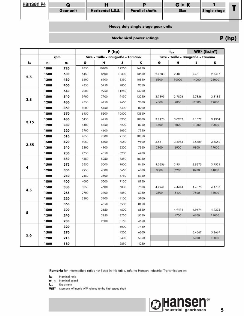
Mechanical power ratings
iN
rpm
n1 n2
P (hp) Size - Taille - Baugröße - Tamaño
G H J K
iex
Size - Taille - Baugröße - Tamaño
G H
WR2 (lb.in2)
J K
2.5
1800
1500
720
600
1200
1000
480
400
7650
6450
10200
8600
5200
4350
6900
5750
12250
10300
16250
13550
8350
7000
10850
9050
2.4783 2.48
5500 10000
2.48 2.5417
14000 25000
2.8
1800
1500
640
540
1200
1000
430
360
3.15
1800
1500
570
480
1200
1000
380
320
7000
5900
9250
7700
4750
4000
6150
5150
11250
9450
14700
12250
7650
6400
9800
8200
6450
5450
8300
6950
4400
3700
5550
4600
10600
8900
12850
10800
7200
6050
8750
7350
2.7895 2.7826
4800 9000
2.7826 2.8182
12500 22000
3.1176 3.0952
4500 8000
3.1579 3.1304
11000 19000
3.55
1800
1500
510
420
1200
1000
340
280
4
1800
1500
450
375
1200
1000
300
250
4850
4050
7300
6100
3300
2750
4900
4050
9100
7650
10850
9100
6200
5200
7350
6200
4350
3650
5950
5000
2950
2450
4000
3400
8350
7000
10050
8450
5650
4750
6800
5750
4.5
1800
1500
400
330
1200
1000
265
220
5
1800
1500
360
300
1200
1000
240
200
4000
3350
5500
4600
2700
2300
3700
3100
7150
6000
8950
7500
4850
4100
6050
5100
4350
3650
2950
2500
5500
4600
8150
6850
3750
3150
5550
4650
3.55 3.5263
3900 6900
3.5789 3.5652
9800 17000
4.0556 3.95
3300 6200
3.9375 3.9524
8700 14800
4.2941 4.4444
3100 5400
4.4375 4.4737
7500 13000
4.9474
4700
4.9474 4.9375
6600 11000
5.6
1800
1500
320
270
1200
1000
215
180
5000
4200
7450
6300
3400
2850
5050
4250
5.4667 5.2667
5900 10000
Heavy duty single stage gear units
QGear unit
HHorizontal L.S.S.
PParallel shafts
GGGG KKKKSize Single stage
1 T
P (hp)
iN Nominal ration1, 2iex
Nominal speedExact ratio
WR2 Moments of inertia WR2 related to the high speed shaft
Remark: for intermediate ratios not listed in this table, refer to Hansen Industrial Transmissions nv.
5
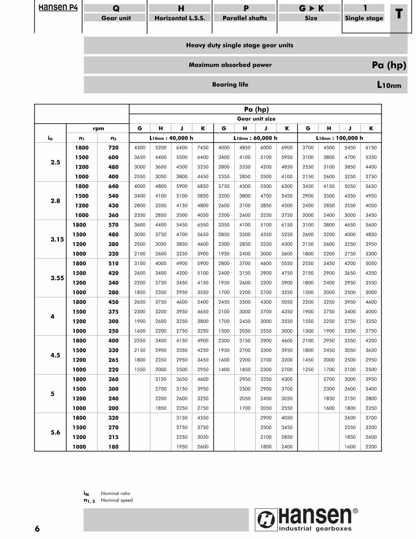
Maximum absorbed power
6
rpm
Pa (hp) Gear unit size
G H J K G H J K G H J K
iN
2.5
n1
1800
n2
720
1500
1200
600
480
L10nm : 40,000 h
4300 5200
3650
3000
4400
3600
6400 7450
5500
4500
6400
5250
L10nm : 60,000 h
4000 4850
3400
2800
4100
3350
6000 6900
5100
4200
5950
4850
L10nm : 100,000 h
3700 4500
3100
2550
3800
3100
5450 6150
4700
3850
5350
4400
2.8
1000
1800
400
640
1500
1200
540
430
3.15
1000
1800
360
570
1500
1200
480
380
2550
4000
3050
4800
3400
2800
4100
3350
3800
5900
4450
6850
5100
4150
5850
4800
2350
3600
2850
4400
3050
2500
3750
3050
3500
5450
4050
6550
4700
3850
5650
4600
2350
3750
2850
4500
3200
2600
3800
3100
3500
5500
4100
6300
4700
3850
5450
4500
2200
3350
2600
4100
2850
2300
3500
2850
3250
5100
3750
6150
4350
3550
5250
4300
2150
3450
2600
4150
2900
2400
3500
2850
3250
5050
3750
5650
4350
3550
4950
4050
2000
3100
2400
3800
2600
2150
3200
2600
3000
4650
3450
5600
4000
3250
4850
3950
3.55
1000
1800
320
510
1500
1200
420
340
4
1000
1800
280
450
1500
1200
375
300
2100
3100
2600
4000
2600
2200
3400
2750
3250
4900
3900
5900
4200
3450
5100
4150
1850
2650
2350
3750
2300
1900
3200
2600
2950
4600
3550
5400
3950
3250
4650
3800
4.5
1000
1800
250
400
1500
1200
330
265
5
1000
1800
220
360
1500
1200
300
240
1600
2550
2200
3400
2150
1800
2900
2350
2750
4150
3250
4900
3550
2950
4250
3450
1550 2000
3150
2700
2200
2500
3650
2950
4600
3150
2600
3950
3250
1950
2800
2400
3700
2400
1950
3150
2600
3000
4600
3600
5550
3900
3200
4750
3900
1700
2450
2200
3500
2100
1700
3000
2450
2700
4300
3250
5050
3700
3000
4350
3550
1800
2550
2200
3450
2150
1800
2900
2400
2750
4200
3300
5050
3650
2950
4350
3550
1500
2200
2000
3250
1900
1550
2750
2250
2500
3950
3000
4600
3400
2750
4000
3250
1500
2300
2050
3150
1950
1600
2700
2200
2550
3900
3000
4600
3300
2700
3950
3200
1400 1850
2950
2500
2050
2300
3350
2700
4300
2900
2400
3700
3050
1300
2100
1900
2950
1800
1450
2450
2000
2350
3550
2750
4200
3050
2500
3650
2950
1250 1700
2700
2300
1850
2100
3000
2500
3950
2600
2150
3400
2800
5.6
1000
1800
200
320
1500
1200
270
215
1000 180
1850 2250
3150
2750
4350
2750
2250
3750
3050
1950 2600
1700 2050
2900
2550
4050
2500
2100
3450
2850
1800 2400
1600 1800
2600
2350
3700
2250
1850
3200
2600
1600 2200
Heavy duty single stage gear units
QGear unit
HHorizontal L.S.S.
PParallel shafts
GGGG KKKKSize Single stage
1 T
Pa (hp)
iN Nominal ration1, 2 Nominal speed
Bearing life L10nm

Lubrication
Heavy duty single stage gear units
QGear unit
HHorizontal L.S.S.
PParallel shafts
GGGG KKKKSize Single stage
1 T
iN Nominal ratioPa Absorbed power
7
2.5 2.8 3.15 3.55 4 4.5 2.5 2.8 3.15 3.55 4 4.5 5 2.5 2.8 3.15 3.55 4 4.5 5 5.6 2.5 2.8 3.15 3.55 4 4.5 5 5.6
500
0
1000
1500
2000
2500
3000
3500
4000
4500
5000
5500
6000
6500
7000
7500
8000
8500
9000
9500
QHPG1T QHPH1T QHPJ1T QHPK1T
iN
Pa (hp)
The above mentioned graph gives an indication of the lubrication boundaries. Refer to Hansen Industrial Transmissions nv for an in-depth verification.
Gear unit's oil volume is sufficiently large to lubricate the gear unit.
Special measures should be taken to ensure the lubrication. Refer to Hansen Industrial Transmissions nv.
Additional external oil volume is required.
Graph valid under the following conditions:- Oil temperature at gear unit’s oil inlet: 160° F- Input speed n1: 1800 or 1200 rpm- Viscosity of mineral oil: ISO VG 220- Motor pump 60Hz - 1800 rpm
8
Heavy duty single stage gear units
QGear unit
HHorizontal L.S.S.
PParallel shafts
GGGG KKKKSize Single stage
1 T
X
Y
D
ZDIN332"D"
XA
YA
DA
ZADIN332"D"
C
FP
RM
E F
RM
FP
A
CU CV
(1)
D
GS
GS
6xTS
L
LAFS
K
CA
FT FU
DA
J
JA
H TR
GP
B
G GP
4xT
H
G
RL LR
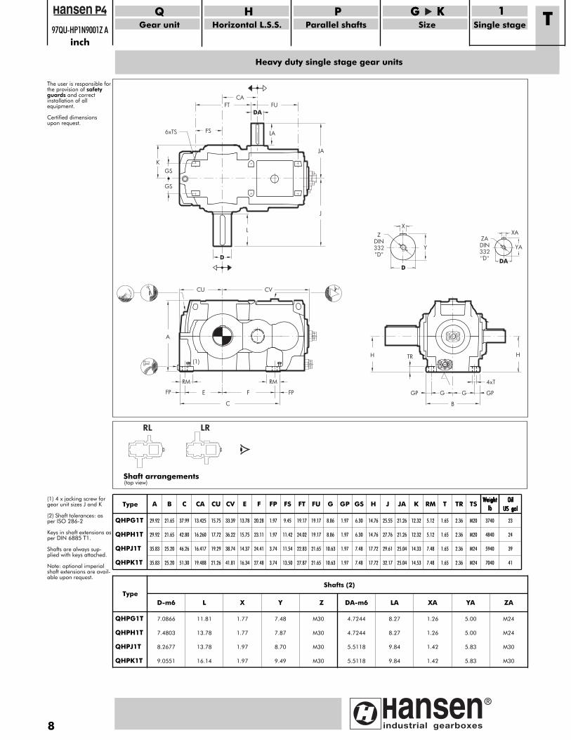
Shaft arrangements(top view)
Type A B C CA CU CV E F FP FS FT FU G GP GS H J JA K RM T TR TSWWWWeeeeiiiigggghhhhtttt
llllbbbbOOOOiiiillll
UUUUSSSS ggggaaaallll
QHPG1T
QHPH1T
29.92
29.92
21.65
21.65
37.99
42.80
13.425
16.260
15.75
17.72
33.39
36.22
13.78
15.75
20.28
23.11
1.97
1.97
9.45
11.42
19.17
24.02
19.17
19.17
8.86
8.86
1.97
1.97
6.30
6.30
14.76
14.76
25.55
27.76
21.26
21.26
12.32
12.32
5.12
5.12
1.65
1.65
2.36
2.36
M20
M20
3740
4840
23
24
QHPJ1T
QHPK1T
35.83
35.83
25.20
25.20
46.26
51.30
16.417
19.488
19.29
21.26
38.74
41.81
14.37
16.34
24.41
27.48
3.74
3.74
11.54
13.50
22.83
27.87
21.65
21.65
10.63
10.63
1.97
1.97
7.48
7.48
17.72
17.72
29.61
32.17
25.04
25.04
14.33
14.53
7.48
7.48
1.65
1.65
2.36
2.36
M24
M24
5940
7040
39
41
TypeShafts (2)
QHPG1T
D-m6
7.0866
L
11.81
X
1.77
Y
7.48
Z
M30
DA-m6
4.7244
LA
8.27
XA
1.26
YA
5.00
ZA
M24
QHPH1T
QHPJ1T
QHPK1T
7.4803
8.2677
13.78
13.78
9.0551 16.14
1.77
1.97
7.87
8.70
1.97 9.49
M30
M30
4.7244
5.5118
M30 5.5118
8.27
9.84
1.26
1.42
9.84 1.42
5.00
5.83
M24
M30
5.83 M30
The user is responsible forthe provision of safetyguards and correctinstallation of allequipment.
Certified dimensionsupon request.
(1) 4 x jacking screw forgear unit sizes J and K
(2) Shaft tolerances: asper ISO 286-2
Keys in shaft extensions asper DIN 6885 T1.
Shafts are always sup-plied with keys attached.
Note: optional imperialshaft extensions are avail-able upon request.
97QU-HP1N9001Z Ainch
Heavy duty single stage gear units
QGear unit
HHorizontal L.S.S.
PParallel shafts
GGGG KKKKSize Single stage
1 T97QU-H000C004Z A
inch
9
AL
BL
CL
DL
OC
OA
OB
12
3
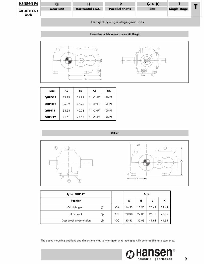
Options
Type QHP.1T Size
Position
Oil sight glass OA
G
16.93
H
18.90
J
20.47
K
22.44
Drain cock
Dust-proof breather plug
OB
OC
20.08
35.63
22.05
35.63
26.18
41.93
28.15
41.93
The above mounting positions and dimensions may vary for gear units equipped with other additional accessories.
Type AL BL CL DL
QHPG1T
QHPH1T
33.19
36.02
34.92
37.76
1 1/2NPT
1 1/2NPT
2NPT
2NPT
QHPJ1T
QHPK1T
38.54
41.61
40.28
43.35
1 1/2NPT
1 1/2NPT
2NPT
2NPT
Connection for lubrication system - SAE flange
HTR
GPB
GGP
4xT
H
G
CFP
RM
EF
RM
FP
A
CU
CV
(1)
X
Y
D
ZDIN
332
"D"
XA
YA
DA
ZA
DIN
332
"D"
D
GS
GS
6xTS
L
LA
FS
K
CA
FTFU
DA
J
JA
626 E
standardized heavy duty single stage gear units
See our worldwidesales & service network at
www.hansenindustrialgearboxes.com
DO
C-C
AI6
26E/
0713
Hansen Industrial Transmissions nvLeonardo da Vincilaan 1B-2650 Edegem - BelgiumT. +32(0)3 450 12 11F. +32(0)3 450 12 20E. [email protected]
www.hansenindustrialgearboxes.com
Hansen Industrial Transmissions nv commits
to be a pioneering innovator.
The production of high performance
gear units stems from an interactive
partnership with our clients, the end users
and the actively engaged manpower of
our global enterprise. Embracing design,
manufacturing and customer services,
Hansen Industrial Transmissions has grown into
a world leader in its field.
Today, we set standards for both product
and working environment, inciting a
knowing environment to seize all new
and inspiring technologies.