Embed Size (px)
Citation preview

External Use
TM
Hands-On Workshop: Small Engines,
Methods and Solutions for Reducing
Small Engine Emissions
FTF-AUT-F0184
A P R . 2 0 1 4
Safa Matin | Sr. System & Software Engineer

TM
External Use 1
Agenda
• Small Engine Control - Analog Solutions
− Freescale analog small engine controllers:
MC33812 – Low-end single cylinder
MC33813 – Mid-range single cylinder
MC33814 – Mid-range dual cylinder
Comparison of all three analog circuits
Packaging options (SiP)
Microcomputer options
− Evaluation boards and reference designs
SiP

TM
External Use 2
Small Engine Control Solutions
• Magneto/Carburetor
− Advantages: Lowest cost, mature, reliable, well known and
understood
− Disadvantages: Fixed spark, cold start problem, low efficiency
• Capacitive Discharge (CDI)/ Carburetor
− Advantages: Good spark, relatively low cost
− Disadvantages: Fixed spark, cold start problem, low efficiency
• Transistor (TCI)/ E-Carburetor
− Advantages: Microcontroller provides adjustable spark,
moderate cost
− Disadvantages: Needs battery, may be open loop on fuel

TM
External Use 3
Small Engine Control Solutions
• Electronic Fuel Injection (EFI)
− Advantages: Programmable fuel and spark, closed loop with O2 sensor,
can reduce emissions, higher efficiency
− Disadvantages: Higher cost, complexity, development time
• Direct Fuel Injection (DFI)
− Advantages: Programmable fuel and spark, closed loop with O2 sensor,
can reduce emissions, higher efficiency
− Disadvantages: Highest cost, complexity, development time

TM
External Use 4
Engine Temp
Accelerator
Position
Inlet Air
Temp
Manifold
pressure
ADC
VCC (+5V)
Regulator
Reset
Power
ISO9141
SCI
CAN
I/O
Clutch
Sidestand
O2 sensor
Watchdog
Tilt
SPI
INTR. Timers
MCU
S12P /
S12XS
+5V
MC33812
Smart MOS8MV
MC33812 for One Cylinder Low End ECU
CAN
Crankshaft sensor
VRS input
Fuel
Injector
Pre-Driver
Driver
IGBT or Darlington
coil driver
Driver P
ara
llel
2.0A
1.0A
MIL
Lamp
Fuel
Pump Driver 2.0A

TM
External Use 5
ECU Using MC33813 (Single Cyl) or MC33814 (Dual Cyl)
Fuel
Injectors
Inlet Air
Temp
Manifold
pressure
ADC
Pre-
Regulator
SMOS
Driver *
Pre-Driver *
Driver
Reset Power
MCU
Driver
ISO9141
CAN
SCI
CAN
SPI
I/O
Clutch
Sidestand
O2 sensor
Watchdog
IGBT coil
drivers
Driver
Pre-Driver SPI
Pa
ralle
l
Pre-Driver
Relay
Driver
2A
1.3A
1.3A
1A
Crankshaft sensor
VRS input INTR.
1A 50 mA
Sensor
Regulator
100 mA
Sensors
Timers
VCC
Regulator
MIL
Lamp
Tilt
Engine
Temp
Accelerator
Position
O2 sensor
heater
Diag/Cluster
Battery
Fuel
Pump
Ignition
Keyswitch
Logic
Tachometer
Driver
200 mA
* = Available on MC33814
. (Not available on MC33813)
Note: Both support VRS output internally

TM
External Use 6
MC33813, MC33814 Low Side Drivers
All low side drivers have similar features:
(INJ1, INJ2, REL1, REL2, TACH, LAMP)
• Output control via parallel input or SPI input (logic OR or AND)
• Can be PWM with internal PWM or external PWM, or frequency
• Protected against short to battery, over current and over temperature
• Can detect open load (OL) or short to ground (SG) faults
• OL current sink and SG current source can be turned off via SPI
• Can either shut down output or retry on fault, selectable in SPI
• All faults communicated to MCU via SPI
• Can be set to ignore in-rush current, selectable in SPI
• Each low side driver has its own SPI configuration, control & status register
• All SPI registers can be read and written to by the MCU

TM
External Use 7
MC33813, MC33814 Tachometer Driver
Three different modes of operation:
1) Outputs same signal as VRSOUT only divided by ‘N’
− Where N=1 to 31 selectable in SPI Configuration Register
− Can drive up to a 50 ma. meter movement
2) Low Side Driver controlled by SPI with PWM
− Useful when MCU controls RPM output to meter
− Can be used as speedometer driver or other meter function
− Can be used as a general purpose LED driver with dimming
3) Outputs a fixed frequency from 10 HZ to 100 KHz (8 different
values)
− Useful for implementing CDI high voltage generator
− Can provide external frequency source for other PWM applications

TM
External Use 8
MC33813, MC33814 Pre-Drivers
All three pre-drivers have similar features:
(IGN1, IGN2, O2Heater)
• Any pre-driver can be used as ignition or general purpose gate drive (GPGD)
• Ignition pre-drivers drive IGBTs, and GPGD pre-drivers drive MOSFETs
• Output control via parallel input or SPI input (logic OR or AND)
• Can be PWM’d with internal PWM or external PWM, or frequency
• Protected against short to battery and over current
• Can detect open load (OL)
• OL current sink can be turned off via SPI
• Can shut down output or retry on fault, selectable in SPI
• All faults annunciated to MCU via SPI
• Each pre-driver has its own SPI configuration, control & status register
• All SPI registers can be read and written to by the MCU

TM
External Use 9
MC33813, MC33814 Voltage Regulators
6.5 V Pre-Regulator and Two 5V Regulators:
• Pre-regulator uses external PNP so output current required
determines size of external transistor and package type
• One 5V regulator for MCU VCC supply up to 200 mA
• One 5V regulator tracks VCC +/- 20 mV up to 100 mA
− Protected against short to battery, ground, over temperature
− Can be controlled by MCU
Pre-
regulator
(6.5V) VPWR
Regulator
(5V) To MCU
Tracking
Regulator
(5V)
To Sensors
VPPREF
VPPSENS VCC
VPROT
(200 ma)
(100 ma)
TM
External Use 10
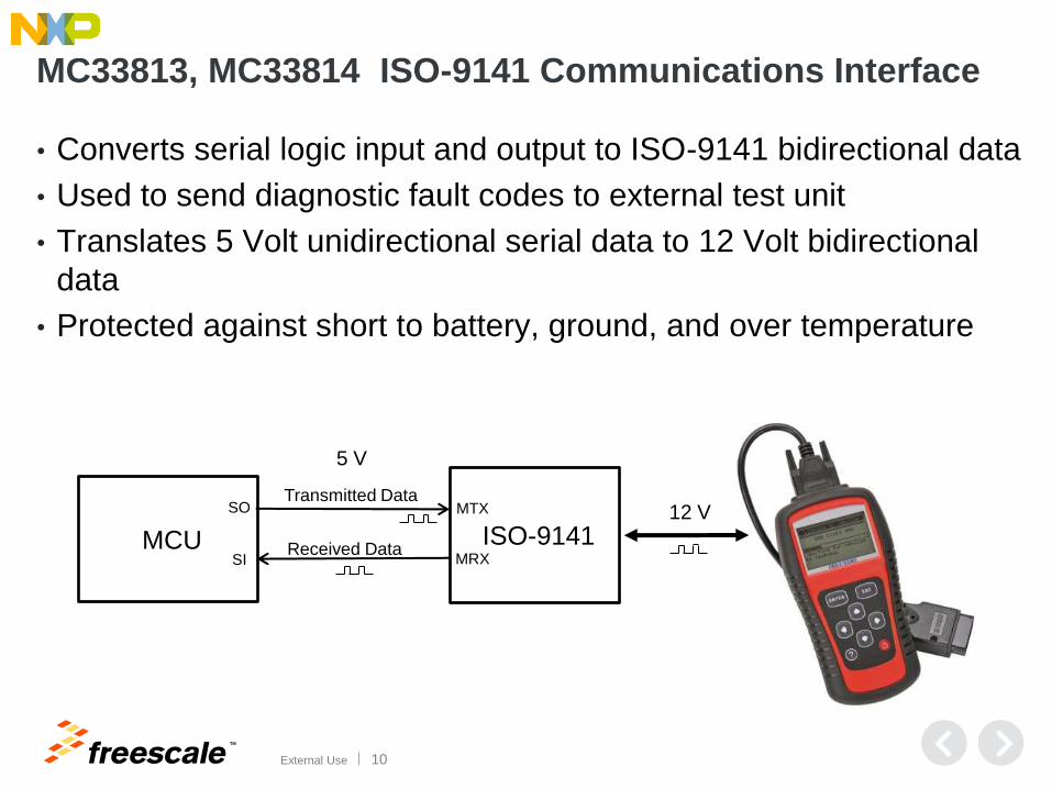
MC33813, MC33814 ISO-9141 Communications Interface
• Converts serial logic input and output to ISO-9141 bidirectional data
• Used to send diagnostic fault codes to external test unit
• Translates 5 Volt unidirectional serial data to 12 Volt bidirectional
data
• Protected against short to battery, ground, and over temperature
MCU ISO-9141
MTX Transmitted Data
Received Data MRX
SO
SI
5 V
12 V
TM
External Use 11
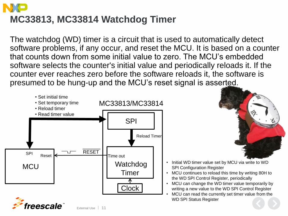
MC33813, MC33814 Watchdog Timer
The watchdog (WD) timer is a circuit that is used to automatically detect software problems, if any occur, and reset the MCU. It is based on a counter that counts down from some initial value to zero. The MCU’s embedded software selects the counter's initial value and periodically reloads it. If the counter ever reaches zero before the software reloads it, the software is presumed to be hung-up and the MCU’s reset signal is asserted.
MCU Watchdog
Timer
Reload Timer
• Set initial time
• Set temporary time
• Reload timer
• Read timer value
RESET Reset
SPI
SPI Time out
MC33813/MC33814
Clock
• Initial WD timer value set by MCU via write to WD
SPI Configuration Register
• MCU continues to reload this time by writing 80H to
the WD SPI Control Register, periodically
• MCU can change the WD timer value temporarily by
writing a new value to the WD SPI Control Register
• MCU can read the currently set timer value from the
WD SPI Status Register
TM
External Use 12
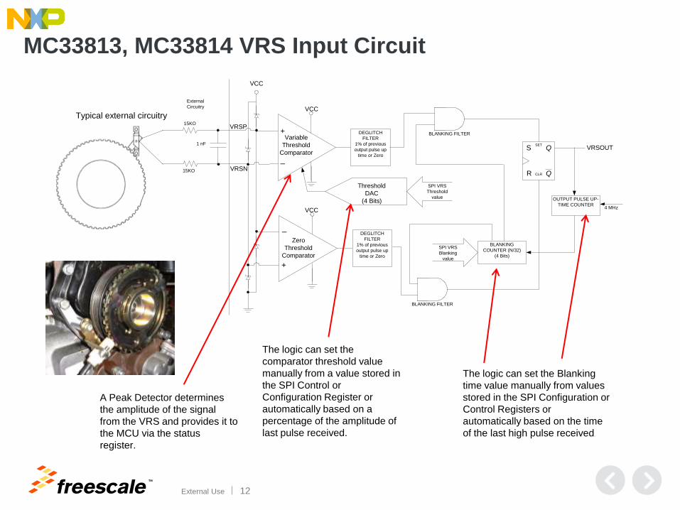
MC33813, MC33814 VRS Input Circuit
Variable
Threshold
Comparator
Zero
Threshold
Comparator
Threshold
DAC
(4 Bits)
+
+
_
_
VCC
VCC
SPI VRS
Threshold
value
DEGLITCH
FILTER
1% of previous
output pulse up
time or Zero
DEGLITCH
FILTER
1% of previous
output pulse up
time or Zero
Q
QSET
CLR
S
R
VRSO
UT
External
Circuitry
VCC
15KO
15KO
1 nF
VRSN
VRSPBLANKING FILTER
BLANKING FILTER
OUTPUT PULSE UP-
TIME COUNTER
BLANKING
COUNTER (N/32)
(4 Bits)
VRSOUT
SPI VRS
Blanking
value
4 MHz
Typical external circuitry
The logic can set the
comparator threshold value
manually from a value stored in
the SPI Control or
Configuration Register or
automatically based on a
percentage of the amplitude of
last pulse received.
The logic can set the Blanking
time value manually from values
stored in the SPI Configuration or
Control Registers or
automatically based on the time
of the last high pulse received.
A Peak Detector determines
the amplitude of the signal
from the VRS and provides it to
the MCU via the status
register.
TM
External Use 13
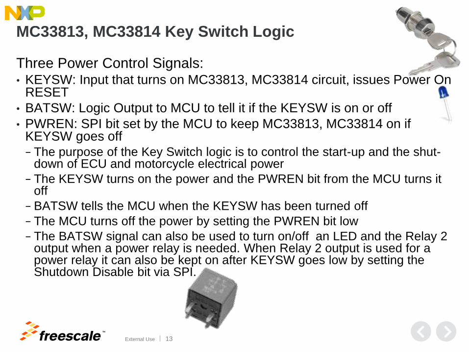
MC33813, MC33814 Key Switch Logic
Three Power Control Signals: • KEYSW: Input that turns on MC33813, MC33814 circuit, issues Power On
RESET
• BATSW: Logic Output to MCU to tell it if the KEYSW is on or off
• PWREN: SPI bit set by the MCU to keep MC33813, MC33814 on if KEYSW goes off
− The purpose of the Key Switch logic is to control the start-up and the shut-down of ECU and motorcycle electrical power
− The KEYSW turns on the power and the PWREN bit from the MCU turns it off
− BATSW tells the MCU when the KEYSW has been turned off
− The MCU turns off the power by setting the PWREN bit low
− The BATSW signal can also be used to turn on/off an LED and the Relay 2 output when a power relay is needed. When Relay 2 output is used for a power relay it can also be kept on after KEYSW goes low by setting the Shutdown Disable bit via SPI.

TM
External Use 14
Function MC33812 MC33813 MC33814 Comments
Injector Driver(s) One (2A) One (1.3A) Two (1.3A,1.3A)
Relay/Other Driver(s) One (2A) Two (2A, 1A) Two (2A, 1A) Fuel pump, relays,
fan, canister, etc.
Lamp Driver One (1A) One (1A) One (1A)
Tachometer Driver None One (50mA)* One (50mA)* *low side
LED Driver None One (30mA)++ One (30mA)++ ++high side
Ignition Pre-Driver(s) One-
One--
Two--
- IGBT Only
-- IGBT &
Darlington
O2 Heater Pre-Driver None One One IGBT/MOSFET
VRS Input Circuit None One One
Voltage Regulator(s) One 5V Two 5Vw Two 5Vw w With pre-regulator
Watchdog Yes Yes Yes
Keyswitch Logic None Yes Yes
ISO-9141 One One One
MCU Communication Parallel Parallel & SPI Parallel & SPI
Small Engine Analog Circuit - Comparison of Functions

TM
External Use 15
SiP (System In Package)
9S12P96, 9S12P128
9S12XS128, 9S12XS256
LQFP-64
12 mm X 12 mm
0.5 mm pin pitch
MM912IP812, MM912JP812 (S12P)
MM912JS812,MM912KS812 (S12XS)
LQFP-100-EP
14 mm x14 mm
0.5 mm pin pitch
MC33812
SOICW-32-EP
7.5 mm x 11 mm
0.65 mm pin pitch
MCU
Analog
MM912xS812
Up to 20% board space saving

TM
External Use 16
MC33812 MC33813 MC33814 MM912xP812
• SOICW-32-EP
• 7.5 mm x 11 mm
• 0.65 mm pin pitch
• LQFP-48-EP
• 7 mm x 7 mm
• 0.5 mm pin pitch
• LQFP-48-EP
• 7 mm x 7 mm
• 0.5 mm pin pitch
• LQFP-100-EP
• 14 mm x14 mm
• 0.5 mm pin pitch
MM912xS812
• LQFP-100-EP
• 14 mm x14 mm
• 0.5 mm pin pitch
Small Engine / Powertrain Analog Circuits Packages
TM
External Use 17
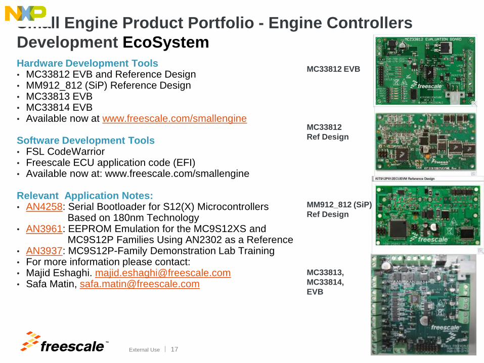
Small Engine Product Portfolio - Engine Controllers
Development EcoSystem
MC33812 EVB
MC33812
Ref Design
MM912_812 (SiP)
Ref Design
MC33813,
MC33814,
EVB
Hardware Development Tools • MC33812 EVB and Reference Design • MM912_812 (SiP) Reference Design • MC33813 EVB • MC33814 EVB • Available now at www.freescale.com/smallengine
Software Development Tools • FSL CodeWarrior • Freescale ECU application code (EFI) • Available now at: www.freescale.com/smallengine
Relevant Application Notes: • AN4258: Serial Bootloader for S12(X) Microcontrollers Based on 180nm Technology • AN3961: EEPROM Emulation for the MC9S12XS and MC9S12P Families Using AN2302 as a Reference • AN3937: MC9S12P-Family Demonstration Lab Training • For more information please contact: • Majid Eshaghi. [email protected] • Safa Matin, [email protected]

TM
© 2014 Freescale Semiconductor, Inc. | External Use
www.Freescale.com