Embed Size (px)
Citation preview

TECHNICALHANDBOOK
Heavy Duty ASME B73.1 A9
Wilfley SealingTechnology
No Flush WaterRequired

1
WILFLEY SEALING TECHNOLOGY
Wilfley Expellers
Wilfley Sealing Technology is the premier sealing solution for the toughest pumping applications and has proven to be a superior alternative to conventional sealing systems like mechanical seals and compression packing. It has been the foundation for every Wilfley pump design, dating back to the ground-breaking Model A slurry pump in 1919.
Wilfley Sealing Technology provides leak free operation at all times by partnering a dynamic seal (page 2) with a static seal (page 3). The dynamic seal prevents leakage while the pump is running and the static seal prevents leakage while the pump is off.
The harmony between the dynamic and static seal is what makes Wilfley Sealing Technology excel beyond conventional seals.

2
WILFLEYdynamic EXPELLER seal
A
FEATURES & BENEFITS:
• A superior alternative to mechanical seals and associated flush systems
• Inherently safe without gland packing or frictional heat
• Product dilution is eliminated
• Operational abuse tolerant, e.g. cavitation and vibration
• Reduces maintenance costs and maximizes production time through increased mean time between maintenance (MTBM)
• Excellent solids handling capabilities
• Intermittent dry running capability
HOW THE WILFLEY DYNAMIC EXPELLER SEAL WORKS:
• A liquid interface (A) is established during pump operation by centrifugal forces generated by the expeller
• This liquid interface effectively isolates the pumped fluid from the shaft
• The DryLock® 2 static seal prevents any leakage when the pump isn't in operation

HOW THE DRYLOCK® 2 SEAL WORKS:
At start up, the expeller (A) establishes a liquid interface that pulls the pumped fluid away from the seal faces. As this happens, centrifugal force moves balls (B) outwards to open seal faces (C) and prevent any rubbing contact.
At shut down, the liquid interface collapses and the pumped fluid is pushed towards the seal faces. An isolated wave spring (D) forces the seal faces to close before any of the pump fluid can escape.
FEATURES & BENEFITS:
• Leak free operation - Small precise seal opening allows for rapid seal actuation
• Reliable and repeatable static seal actuation - The quantity of balls is specifically set for your application
• Easy to install / maintain - Simple and effective design, no special tools needed
Pump Running / Seal Open
Pump Off / Seal Closed
AB
D
C
3
drylock® 2
STATIC seal

Single Mechanical Seals Double Mechanical Seals Expeller with Packing
4
sealINGoptionsTHE MODEL A9 CAN ALSO ACCOMMODATE A WIDE RANGE OF SEALING OPTIONS
A TOUGH GOVERNOR-ACTUATED STATIC SEAL THAT IS IDEAL FOR:
• Acid slurries
• Crystallizing liquids
• Efflorescents
FEATURES & BENEFITS
• Leak free operation
• Reliable and repeatable static seal actuation
• Heavy duty components for increased seal life
• Simple maintenance-friendly design
• Field adjustable
Solidlock®
STATIC seal

WET END
3 Pressure / temperature balance holes
SEALING
POWER END
9 Convenient lifting point
10 Large sight glasses on both sides to easily verifyoil level
Expeller / seal wash out capability6
4 Opti-expeller provides superior dynamic sealingwith zero operational leakage
DryLock® 2 seal engineered for reliable staticsealing
5
Heavy duty case design with 150 lb. flanges(300 lb. flanges available)
1
Comprehensive hydraulics available to meetyour needs
2
Other sealing options available including mechanicalseals and packing
7 Robust shaft with low L3/D4 ratios minimizesdeflections and increases seal life and reliability
Frame bracket designed to protect bearing unitfrom pumpage (duplex stainless steel optional)
8
11 303SS labyrinth seals prevent oil contamination
12 Easy clearance adjustments via externaladjustment bolts
MODEL A9features & benefits
HEAVY DUTYASME B73.1PROCESS PUMPA9
11
10
8
6
5
4
112
7
9
2
3
5 6

Flat face flanges3
Casing drain4
Extreme duty bearings9
C-face adapter10
Fabricated base plate11
One-piece bearing frame8
Expeller cavity drain7
Seal housing steam jacket6
Casing steam jacket5
Dry thermowell at casing discharge1
300 lb. flanges2
Dry thermowell at seal housing (not shown)
Recessed (vortex) impeller (not shown)
Barske impeller (not shown)
Suction / discharge pressure gauge taps (not shown)
Dry thermowell at expeller cavity (not shown)
Dry thermowell at bearing housing (not shown)
Condition monitoring (not shown)
Channel base plate (not shown)
Non-metallic base plate (not shown)
WET END
SEALING
POWER END
BASE PLATE
DIN flanges (not shown)
MODEL A9 OPTIONS3
4
9
10
11
7
6
51
28
7 8

9
BASE PLATE OPTIONS
CHANNELANSI/Hydraulic Institute Pump Standards, Class CAvailable in mild steel and 316SS
Bent plate constructionANSI B73.1 Dimensions
Available for direct driven configurations only
FABRICATEDANSI/Hydraulic Institute Pump Standards, Class AAvailable in mild steel and 316SS
Heavy duty fully reinforced constructionANSI B73.1 Dimensions
High rigidityAvailable for direct and overhead belt driven configurations
NON-METALLICANSI/Hydraulic Institute Pump Standards, Class AAvailable in various compositions
Non-metallic constructionANSI B73.1 Dimensions
Outstanding corrosion resistance Superior vibration damping
Available for direct and overhead belt driven configurations

10
WILFLEY OPTI-EXPELLER
MODEL A9 IMPELLER OPTIONS
MODEL A9 SHAFT
THE OPTI-EXPELLER IS THE LATESTGENERATION OF THE WILFLEY EXPELLER
• Increased intake head capability
• Less horsepower consumption
• Solids handling capability
THE MODEL A9 HAS ONE OF THE STRONGEST SHAFTS IN THE INDUSTRY WITH INCREDIBLY LOW L3/D4 STIFFNESS RATIOS
STANDARD
Robust impellerfor difficult solutions
BARSKE
For low-flow high-head applications
For solutions with larger particle sizes or fibers
RECESSED (VORTEX)
FRAME 1 FRAME 2 FRAME 3 FRAME 4 FRAME 568 62 28 17 14

WILFLEY MODEL A9CAPACITIES
CAPACITY (M3/HR)
CAPACITY (USGPM)10 10,000100 1,000
10 100 1,000
TOTA
L D
YNA
MIC
HEA
D (F
T)
TOTA
L D
YNA
MIC
HEA
D (M
)
1750 RPM
01
47
10
13
1211
21 2223
2526
27
1719
32 6
5
18
200
100
250
300
350
400
150
50
60
80
100
120
40
20
89
14 1516
20
24
CAPACITY (M3/HR)
CAPACITY (USGPM)10 10,000100 1,000
10 100 1,000
0
TOTA
L D
YNA
MIC
HEA
D (F
T)
3550 RPM
1 2
45
8
6
7
9 1011
1415
13
12
TOTA
L D
YNA
MIC
HEA
D (M
)
600
400
200
700
800
500
300
100
200
150
100
50
250
3
16
CAPACITY (M3/HR)
CAPACITY (USGPM)
TOTA
L D
YNA
MIC
HEA
D (F
T)
TOTA
L D
YNA
MIC
HEA
D (M
)
1150 RPM
10 10,000100 1,000
10 100 1,000
01
47
10
13
1211
21 2217
19
2
5
20
18
23
24
272625
80
40
100
120
140
160
60
20
20
30
40
50
10
3 6
8 9
1415 16
11

1450 RPM
CAPACITY (M3/HR)101 100 1,000
10 100 1,000
TOTA
L D
YNA
MIC
HEA
D (F
T)
CAPACITY (USGPM)
TOTA
L D
YNA
MIC
HEA
D (M
)
1
47
10
13
1211
21 2223
2526 27
1719
2
5
20
18 100
150
200
250
50
0
40
20
50
60
70
80
30
103 6
89
14 1516 24
CAPACITY (M3/HR)101 100 1,000
10 100 1,000
0
120
80
40
140
160
180
100
60
20
300
400
500
200
100 TOTA
L D
YNA
MIC
HEA
D (F
T)
CAPACITY (USGPM)
TOTA
L D
YNA
MIC
HEA
D (M
)
2950 RPM
1
4 5
8
7
9 1011
1413
12
15
2 3
6
16
17
18
950 RPM
CAPACITY (M3/HR)
TOTA
L D
YNA
MIC
HEA
D (F
T)
CAPACITY (USGPM)
TOTA
L D
YNA
MIC
HEA
D (M
)
101 100 1,000
10 100 1,000
01
47
10
13
1211
21 2217
19
2
5
20
18
23
24
272625
20
10
25
30
35
15
5
40
60
80
100
20
3 6
89
14 1516
FRAME 11. 1.5x1-62. 3x1.5-63. 3x2-64. 1.5x1-8
5. 3x1.5-86. 3x2-87. 4x3-88. 2x1-10
9. 3x1.5-1010. 3x2-1011. 4x3-1012. 6x4-10
13. 3x1.5-1314. 3x2-1315. 4x3-1316. 4x3-13H17. 6x4-1318. 6x4-13H
19. 8x6-1320. 6x4-1521. 8x6-1522. 8x6-15H23. 10x8-1724. 10x8-17H
25. 6x4-1926. 8x6-1927. 10x8-19
FRAME 2 FRAME 3 FRAME 4 FRAME 5
12

model a9 RECESSED (Vortex)CAPACITIES
CAPACITY (USGPM)
010 100 1,000
1150 RPM
CAPACITY (M3/HR)10 100 1,000
80
40
60
20
20
10
TOTA
L D
YNA
MIC
HEA
D (M
)
TOTA
L D
YNA
MIC
HEA
D (F
T)
28 29 3031
0
1450 RPM40
20
30
10
100
50
CAPACITY (M3/HR)
TOTA
L D
YNA
MIC
HEA
D (F
T)
TOTA
L D
YNA
MIC
HEA
D (M
)
10 100 1,000
CAPACITY (USGPM)100 1,000
2829 30
0
1750 RPM200
100
150
50
60
40
20
CAPACITY (USGPM)10 100 1,000
CAPACITY (M3/HR)10 100 1,000
TOTA
L D
YNA
MIC
HEA
D (M
)
TOTA
L D
YNA
MIC
HEA
D (F
T)
2829 30
CAPACITY (M3/HR)
TOTA
L D
YNA
MIC
HEA
D (F
T)
TOTA
L D
YNA
MIC
HEA
D (M
)
010 100 1,000
CAPACITY (USGPM)100 1,000
950 RPM20
10
15
5
40
60
20
28 29 3031
13

model a9 LOW-FLOW HIGH-HEADCAPACITIES
28. 2.5x2-1329. 4x4-1330. 6x6-1331. 10x10-16
32. 2x1-9 A33. 2x1-9 B34. 2x1-9 C35. 2x1-10 A36. 2x1-10 B37. 2x1-10 C
A9R – RECESSED (VORTEX) A9LF – LOW-FLOW HIGH-HEAD
TOTA
L D
YNA
MIC
HEA
D (F
T)
TOTA
L D
YNA
MIC
HEA
D (M
)
CAPACITY (M3/HR)1 10
VARIABLE SPEED
3235 33
36
34
37
CAPACITY (USGPM)10 1001
0
600
400
200
700
500
300
100
200
150
100
50
14

ItemName
STANDARD MATERIALSDuctile Iron 304L 316L Alloy 20 CD4MCuN WCD4TM
WET ENDCap Screws 18-8Case Gasket Gylon®
Case Plate Ductile Iron 304L 316L Alloy 20 CD4MCuN WCD4™Casing Ductile Iron 304L 316L Alloy 20 CD4MCuN WCD4™Expeller Ductile Iron 304L 316L Alloy 20 CD4MCuN WCD4™Impeller Ductile Iron 304L 316L Alloy 20 CD4MCuN WCD4™O-rings Viton® (Kalrez®, Teflon-Coated Viton®, EPDM Optional)
SEALDryLock® 2 CD4MCuN 304L 316L Alloy 20 CD4MCuN WCD4™POWER ENDBearing Frame Ductile IronBearing Locknut SteelFrame Bracket Ductile Iron (CD4MCuN Optional)
Frame Foot Ductile IronInboard Bearing Single-Row Deep GrooveInboard Bearing Cover 316SSINPRO® VBXS Oil Seal 303SSOil Sight Glass Glass/SteelO-rings Viton®
Outboard Bearing Double-Row Deep Groove (2x Single-Row Angular Contact Optional)
Shaft SAE4140 (316SS, Nitronic 50, Ferralium 255 Optional)
materials
Some of Wilfley’s most recent innovations include:
WCD4™ - better corrosion / erosion resistance than conventional CD4MCuN
Alloy C Max - better corrosion resistance than CW2M
MAXALLOY® 5 - a machinable 27% chrome hard iron with an average hardness of 645 HBN
WILFLEY knows metallurgy
15
Wilfley works discreetly with key suppliers, such as Western Foundries, to provide a variety of engineered metallurgies and proprietary
processes for the longest possible pump and parts life and reliability.

CONSTRUCTIONDETAILS
16
FRAME 3 FRAME 43x1.5-13A20-13
3x2-13A30-13
4x3-13 / HA40-13
6x4-13 / HA80-13
8x6-13A90-13
6x4-15A105-15
8x6-15 / HA110-15
10x8-17 / HA120-17
GENERALPumpWeight
lbs 480 490 490 520 960 710 1,100 1,250kg 218 222 222 236 435 322 499 567
Max.Solids Size
in 0.25 0.375 0.375 0.375 0.5 0.5 0.5 0.5mm 6 10 10 10 13 13 13 13
SHAFTDiameter at
Impellerin 1.625 2.25
mm 41 57Diameter atCoupling
in 1.625 2.375mm 41 60
BEARINGSHeavyDuty
Radial 6312 6319Thrust 5312A 7319BECB
ExtremeDuty
Radial 21312E 21319EThrust 7312BECB 7319BECB
FRAME 1 FRAME 21.5x1-6
AA-63x1.5-6
AB-63x2-6AC-6
1.5x1-8AA-8
3x1.5-8A50-8
3x2-8A60-8
4x3-8A70-8
2x1-10A05-10
3x1.5-10A50-10
3x2-10A60-10
4x3-10A70-10
6x4-10A80-10
GENERALPumpWeight
lbs 145 150 170 145 305 315 325 290 295 310 335 420kg 66 68 77 66 138 143 147 132 134 141 152 190
Max.Solids Size
in 0.188 0.25 0.25 0.313 0.25 0.25 0.375 0.25 0.375 0.375 0.375 0.375mm 5 6 6 8 6 6 10 6 10 10 10 10
SHAFTDiameter at
Impellerin 1 1.25
mm 25 32Diameter atCoupling
in 0.875 1.125mm 22 29
BEARINGSHeavyDuty
Radial 6308 6311Thrust 5208A 5310A
ExtremeDuty
Radial N/A 6311Thrust N/A 7310BECB
FRAME 5 LOW FLOW RECESSED6x4-19
-8x6-19
-10x8-19
-2x1-9
-2x1-10
-2.5x2-13
-4x4-13
-6x6-13
-10x10-16
-
GENERALPumpWeight
lbs 1,390 1,455 1,650 240 240 680 870 1,025 2,190kg 630 660 748 109 109 308 395 465 993
Max.Solids Size
in 0.5 0.5 0.5 0.188 0.188 1 1 1 1mm 13 13 13 5 5 25 25 25 25
SHAFTDiameter at
Impellerin 2.375 1 1.625 2.25
mm 60 25 41 57Diameter atCoupling
in 2.875 0.875 1.625 2.375mm 73 22 41 60
SHAFTHeavyDuty
Radial N/A 6308 6312 6319Thrust N/A 5208A 5312A 7319BECB
ExtremeDuty
Radial 21319E N/A 21312E 21319EThrust 7319BECB N/A 7312BECB 7319BECB

DIMENSIONS
17
X
D
HE HEHA
HLHP
Z
HFHB
4X ØHH HG
ØU
HTCPY
HD L
PUMP DIMENSIONSDimensions in inches (millimeters)
Pump Size CP D L U X Y Z KEYWAYFRAME 1
1.5x1-6 (AA-6)
17.5 (445) 5.25 (133) 4 (102)
0.88 (22)
6.5 (165)
4 (102) -0.19 x 0.09
(5 x 2)
3x1.5-6 (AB-6) 6.5 (165)
3x2-6 (AC-6) 6.5 (165)
1.5x1-8 (AA-8) 6.5 (165)
2x1-9 (A,B,C)16.45 (418) 8.25 (210) 3.3 (84) 7.19 (183)
A = 3.02 (77)B = 2.96 (75)C = 2.89 (73)
5 (127)
2x1-10 (A,B,C) 5.5 (140)
FRAME 23x1.5-8 (A50-8)
23.5 (597)8.25 (210)
4 (102) 1.13 (29)
8.5 (216)
4 (102) - 0.25 x 0.13(6 x 3)
3x2-8 (A60-8) 9.5 (242)
4x3-8 (A70-8) 11 (280)
2x1-10 (A05-10) 8.5 (216)
3x1.5-10 (A50-10) 8.5 (216)
3x2-10 (A60-10) 9.5 (242)
4x3-10 (A70-10) 11 (280)
6x4-10 (A80-10) 10 (254) 13.5 (343)
FRAME 33x1.5-13 (A20-13)
23.5 (597)
10 (254)
4 (102)
1.63 (41)
10.5 (266)
4 (102) -
0.25 x 0.13(6 x 3)
3x2-13 (A30-13) 11.5 (292)
4x3-13 / H (A40-13) 12.5 (318)
6x4-13 / H (A80-13) 13.5 (343)
2.5x2-13 25.25 (641) 5.75 (146) 10 (254) 4 (102) 6.75 (171)
4x4-13 27.5 (699) 8 (203) 12.5 (318) 4.63 (117) 6.13 (156)
6x6-13 32 (813) 12.5 (318) 16 (406) 6 (152) 7 (178)
FRAME 48x6-13 (A90-13)
33.88 (860)14.5 (368)
6 (152)2.38 (60)
16 (406)
6 (152) - 0.63 x 0.31(16 x 8)
6x4-15 (A105-15) 16 (406)
8x6-15 / H (A110-15) 18 (457)
10x8-17 / H (A120-17) 19 (483)
10x10-16 45.5 (1156) 17.64 (448) 18.75 (476) 9 (229) 8.5 (216)
FRAME 56x4-19 33.88 (860) 17.5 (445) 16.25 (413)
2.88 (73)
16.25 (413) 6.25 (159) 12 (305)0.75 x 0.38(19 x 10)8x6-19 34.5 (876) 17.5 (445) 16.25 (413) 16.25 (413) 6.58 (167) 12 (305)
10x8-19 35.38 (899) 20.5 (521) 16.38 (416) 16.38 (416) 7.44 (189) 14.37 (365)
These dimensions are not for construction. Certified dimension prints are available for your specific installation
Flanges are drilled to match ASME B16.5 150lbs.
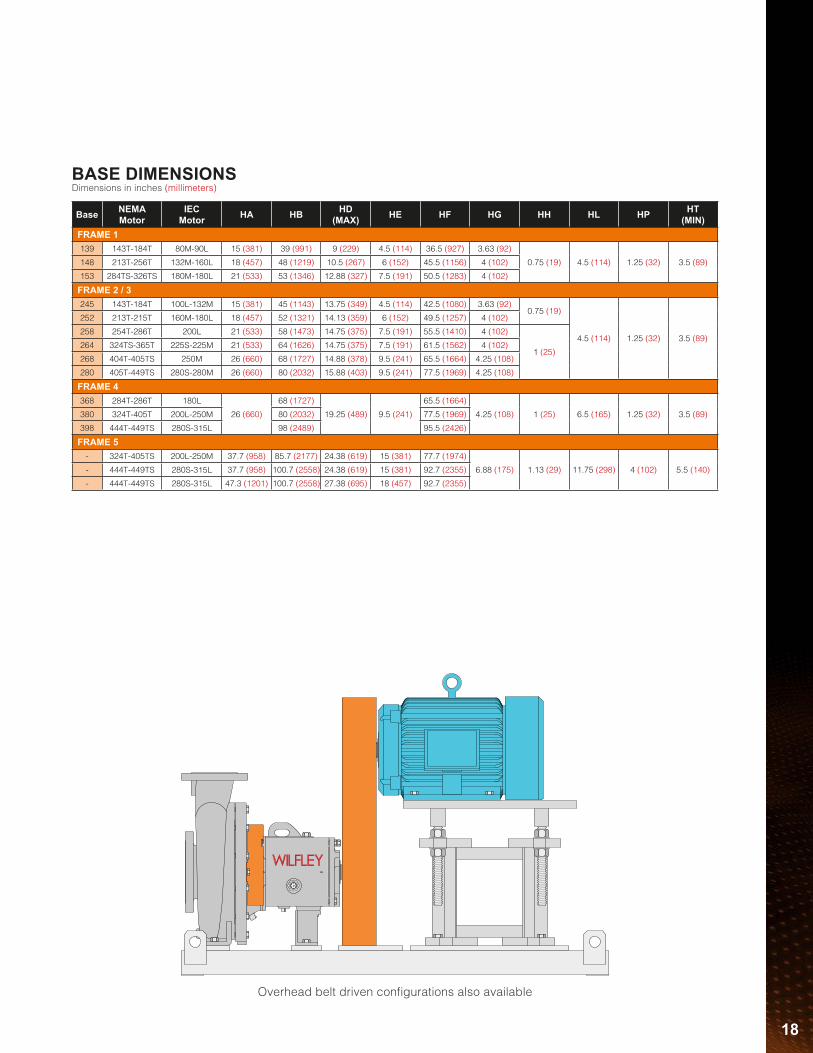
Overhead belt driven configurations also available
18
Base NEMAMotor
IECMotor HA HB HD
(MAX) HE HF HG HH HL HP HT(MIN)
FRAME 1139 143T-184T 80M-90L 15 (381) 39 (991) 9 (229) 4.5 (114) 36.5 (927) 3.63 (92)
0.75 (19) 4.5 (114) 1.25 (32) 3.5 (89)148 213T-256T 132M-160L 18 (457) 48 (1219) 10.5 (267) 6 (152) 45.5 (1156) 4 (102)
153 284TS-326TS 180M-180L 21 (533) 53 (1346) 12.88 (327) 7.5 (191) 50.5 (1283) 4 (102)
FRAME 2 / 3245 143T-184T 100L-132M 15 (381) 45 (1143) 13.75 (349) 4.5 (114) 42.5 (1080) 3.63 (92)
0.75 (19)
4.5 (114) 1.25 (32) 3.5 (89)
252 213T-215T 160M-180L 18 (457) 52 (1321) 14.13 (359) 6 (152) 49.5 (1257) 4 (102)
258 254T-286T 200L 21 (533) 58 (1473) 14.75 (375) 7.5 (191) 55.5 (1410) 4 (102)
1 (25)264 324TS-365T 225S-225M 21 (533) 64 (1626) 14.75 (375) 7.5 (191) 61.5 (1562) 4 (102)
268 404T-405TS 250M 26 (660) 68 (1727) 14.88 (378) 9.5 (241) 65.5 (1664) 4.25 (108)
280 405T-449TS 280S-280M 26 (660) 80 (2032) 15.88 (403) 9.5 (241) 77.5 (1969) 4.25 (108)
FRAME 4368 284T-286T 180L
26 (660)
68 (1727)
19.25 (489) 9.5 (241)
65.5 (1664)
4.25 (108) 1 (25) 6.5 (165) 1.25 (32) 3.5 (89)380 324T-405T 200L-250M 80 (2032) 77.5 (1969)
398 444T-449TS 280S-315L 98 (2489) 95.5 (2426)
FRAME 5- 324T-405TS 200L-250M 37.7 (958) 85.7 (2177) 24.38 (619) 15 (381) 77.7 (1974)
6.88 (175) 1.13 (29) 11.75 (298) 4 (102) 5.5 (140)- 444T-449TS 280S-315L 37.7 (958) 100.7 (2558) 24.38 (619) 15 (381) 92.7 (2355)
- 444T-449TS 280S-315L 47.3 (1201) 100.7 (2558) 27.38 (695) 18 (457) 92.7 (2355)
BASE DIMENSIONSDimensions in inches (millimeters)

visit www.wilfley.comto see our full range of pumping solutions
Kpro® Slurry PumpEMW® Slurry Pump
© A.R. Wilfley and Sons, Inc.A9-TB-EN 2.2Printed in USA • May 2016
5870 E. 56th Avenue, Commerce City, CO 80022, USAToll Free: 1-800-525-9930 • Telephone: +1 (303) 779-1777 • Fax: +1 (303) 779-1277
[email protected] • www.wilfley.com
HEAVY DUTYCENTRIFUGAL PUMPS