Embed Size (px)
Citation preview

73Energy SavingTransducersand ThermoacousticsYoshio Yamasaki
Waseda University, Tokyo, Japan
1 • IntroductionThere are many problems concerning energy and the enviro-nment. It is important to realize energy saving and to use a littleenergy gap. This section describes how to make energy savingtransducers and how to use the sound for energy sources.
The popular cone type of dynamic loudspeaker has evolvedover the years in terms of the materials used for their magnetsand cones, but the basic structure has not changed since 1925when C. E. Rice and E. W. Kellog created them. In fact, it is saidthat “excellent” transducers are available in 500 million differentsizes in Japan. Yet, the efficiency of a transducer, including theamplifier, is less than 0.1%, meaning that more than 99.9% of theenergy is wasted [1]. This section presents the test manufactureof edgeless, damperless, superconductive loudspeakers and high-efficiency electrostatic loudspeakers driven by 1-bit switchingamplifiers [2–4]. The measured speaker and amplifier efficiencieswere 30% and 80%; thus, the total efficiency was 24%.
Thermoacoustic phenomena have been researched for a longtime [5–11]. For example, the Sondhauss tube and the Rijketube, which illustrate fundamental thermoacoustical phenomena,

1350 Y. Yamasaki
are described in “The Theory of Sound” by Lord Rayleigh [12].Sound is a rarefactional wave in air. Therefore, noise can beconsidered to be a form of sound energy. According to thermoa-coustic theory, noise can be exchanged for thermal energy andthus be controlled. In addition, thermal energy can be extractedfrom noise. There are many applications of thermoacoustic theory,such as Stirling engines. A heat supply system whereby noiseis an energy source is a unique idea. Because noise is usuallyabsorbed by some substance before it is finally exchanged forthermal energy, such a system never adds heat loads to theglobal environment. In contrast, noise is usually discharged to anexternal field. It is also very unusual that noise energy is activelyconsumed by its being exchanged. Noise is an unusual type ofenergy because its wastage can be encouraged. When noise, whichoverflows in present-day environments, is exchanged, its energycan be used as a heat supply for purposes such as air-conditioning.Hence, noise can be viewed as an alternative energy source.
2 • Challenges to Improving Dynamic SpeakersThe structure of a cone dynamic speaker is shown in Figure 1.There are two types of resistance: the electrical resistance of thevoice coil and the mechanical resistance of the edge and damperthat holds the cone. Because of them, a large proportion of theenergy supplied to the speaker is wasted. The efficiency (inputelectric power to output acoustic power), which actually reacheda few percent during the “tube age”, is now less than 1% becauseof the use of transistors and much smaller speakers. Moreover,although the efficiency of amplifiers was improved by the intro-duction of semiconductors, it is still only about 10%, meaningthat the total efficiency is less than 0.1%.
The efficiency of cone dynamic speakers can be improvedby minimizing the resistance, reinforcing the magnetic circuit,enlarging the diaphragm, and improving the algorithm. The edge
FIGURE 1Dynamicspeaker. (FromRef. [1].)
Edge
ConeDamper
Voice coil
Magnet
YokeFrame

73 • Energy Saving Transducers and Thermoacoustics 1351
and the damper also cause distortion. In particular, the edge’smovement causes the cone to deteriorate and this shortens thespeaker’s lifespan.
3 • Superconductive Loudspeakers3.1 PeculiarProperties ofthe Super-conductiveState
Superconductivity has the following qualities:
1. zero electrical resistance and ceaseless current flow,2. perfect diamagnetism (the Meissner effect),3. flux quantization whereby the magnetic field is trapped and
objects magnetically float (the pinning effect),4. the Josephson effect whereby current flows with 0 V.
These special qualities have been used in many novel devices, suchas single flux quantum (SFQ) devices, superconducting quantuminterference devices (SQUIDs), and Josephson junctions.
The superconductive state was once thought to be limited tometals and alloys like mercury and Niobium cooled to liquidhelium temperature (4K = –269�), i.e., very close to absolute zero.However, experiments by great experimentalists since the 1980shave demonstrated that superconductive states can be achievedrelatively easily at liquid nitrogen temperatures (77K = –196�).
3.2Compositionof Super-conductiveLoudspeakers
By using superconductive materials, we can fabricate strongmagnetic circuits of high efficiency through the removalof electrical resistance within the voice coil and edgeless,damperless speakers exploiting the pinning effect. A great energysaving can also be expected by connecting such speakers to aswitching amplifier.
Figure 2 shows the composition of an edgeless, damperlessinductive superconductive loudspeaker that we have trialmanufactured. By using induction as opposed to directlyconnecting the voice coil, we could make the cone free ofelectrical wiring, edges, and dampers, and make the cone float in
Cone
Super-conductiveRing
Voice Coil
Magnet
Yoke
FIGURE 2 Super-conductivespeaker. (FromRef. [1].)

1352 Y. Yamasaki
air while in use. We used a simple apparatus that holds it until itbecomes superconductive and lets it go once it has cooled.
For the superconductors, the Y-Ba-Cu-O rare earth singlecrystal superconductive bulk material QMG (manufactured byNippon Steal Corporation) was processed into a ring form with
FIGURE 3 Picture ofsuperconductive speaker.(From Ref. [1].)

73 • Energy Saving Transducers and Thermoacoustics 1353
25.6 mm inner and 29.6 mm outer diameters and a height of3.0 mm, and used it as one-turn voice coils.
Figure 3 shows a picture of the superconductive speaker.
3.3EquivalentCircuit
The equivalent circuit of the inductive speaker in a supercon-ductive state is shown in Figure 4. The speaker constants are asfollows:
primary voice coil resistance: Rc1 = 0–5�primary voice coil inductance: L1 = 0–11 mHsecondary coil inductance: L2 = 0�01 mHcoupling coefficient: k = 0�5–1resonance frequency: F0 = 153�5 Hzresonance Q factor: Qmo = 3�60mass of movement: Md = 2�1 gforce coefficient: B1 = 0�08 Tmradius of cone: a = 22�5 mm
As can be seen from the equivalent circuit, when the primary coilis also superconductive and the coupling coefficient k betweenthe primary and the secondary is 1, all of the electrical inputbecomes a load; thus the output sound pressure level risesdramatically in comparison with conventional speakers, and itshould keep on rising according to the frequency rise withoutconcern for the movement requirement.
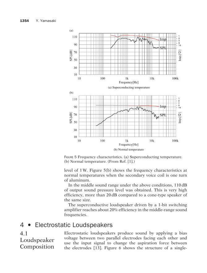
Figure 5(a) shows the superconductive speaker’s frequencycharacteristics for the electrical impedance and output soundpressure level measured 1 m from the speaker for the input
(a) Normal temperature
CemZea
Lem Cem Rem
Zea
k
k
(b) Superconducting temperature
FIGURE 4 Equivalentcircuit. N is the turns ofthe primary voice coil,Lem is compliance ofmovement, Cem is mass ofmovement, Rem ismechanical resistanceand Zea is radiationimpedance. (a) Normaltemperature (b)Superconductingtemperature. (FromRef. [1].)
1354 Y. Yamasaki
(a)
(b)
(b) Normal temperature
(a) Superconducting temperature
FIGURE 5 Frequency characteristics. (a) Superconducting temperature.(b) Normal temperature. (From Ref. [1].)
level of 1 W. Figure 5(b) shows the frequency characteristics atnormal temperatures when the secondary voice coil is one turnof aluminum.
In the middle sound range under the above conditions, 110 dBof output sound pressure level was obtained. This is very highefficiency, more than 20 dB compared to a cone-type speaker ofthe same size.
The superconductive loudspeaker driven by a 1-bit switchingamplifier reaches about 20% efficiency in the middle-range soundfrequencies.
4 • Electrostatic Loudspeakers4.1LoudspeakerComposition
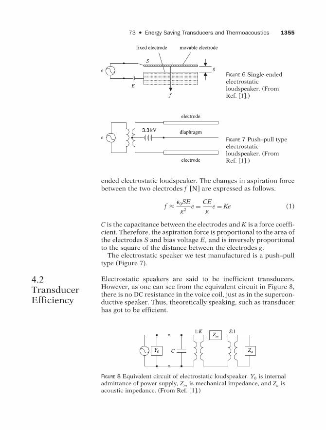
Electrostatic loudspeakers produce sound by applying a biasvoltage between two parallel electrodes facing each other anduse the input signal to change the aspiration force betweenthe electrodes [13]. Figure 6 shows the structure of a single-
73 • Energy Saving Transducers and Thermoacoustics 1355
f
E
S
e g
fixed electrode movable electrode
FIGURE 6 Single-endedelectrostaticloudspeaker. (FromRef. [1].)
3.3 kV
electrode
electrode
diaphragme FIGURE 7 Push–pull type
electrostaticloudspeaker. (FromRef. [1].)
ended electrostatic loudspeaker. The changes in aspiration forcebetween the two electrodes f [N] are expressed as follows.
f ≈ �0SE
g2e = CE
ge = Ke (1)
C is the capacitance between the electrodes and K is a force coeffi-cient. Therefore, the aspiration force is proportional to the area ofthe electrodes S and bias voltage E, and is inversely proportionalto the square of the distance between the electrodes g.
The electrostatic speaker we test manufactured is a push–pulltype (Figure 7).
4.2TransducerEfficiency
Electrostatic speakers are said to be inefficient transducers.However, as one can see from the equivalent circuit in Figure 8,there is no DC resistance in the voice coil, just as in the supercon-ductive speaker. Thus, theoretically speaking, such as transducerhas got to be efficient.
C
1:K S:1
Y0
Zm
Za
FIGURE 8 Equivalent circuit of electrostatic loudspeaker. Y0 is internaladmittance of power supply, Zm is mechanical impedance, and Za isacoustic impedance. (From Ref. [1].)

1356 Y. Yamasaki
Electrostatic speakers do not consume electrical power, andmost of the power becomes reactive. We expect the speaker willbe very efficient when it is connected to a negative-feedbackconstant-current 1-bit amplifier.
5 • One-Bit DrivingIt is effective to induce the switching circuit to make amplifiersof high efficiency. The power loss of the switching amplifier ismainly because of the internal resistance and the switching lossbecause of the gate capacitance and response delay. Therefore,besides improving the power device, it is also possible to reducepower loss by reducing the number of switching times. Wetried to make a high S/N amplifier using the usual switchingdevice by using “Run Length Limited Coding” in the sigma-deltamodulator [14,15] so that high resolution in time domain canbe acquired in the conditional pulse width [16]. As a result, asimulation has shown that a switching amplifier with over 100dB S/N in the audible band should be possible when the pulsewidth is more than 1�s.
6 • ThermoacousticsSwift [17] believes it is very likely that practical uses will befound for thermoacoustic engines, because these engines havethe advantages of reasonable efficiency and extreme simplicity.Another advantage is that these engines can transfer heat withoutusing chlorofluorocarbons.
Swift pointed out that there are two classes of heat engine:prime movers and heat pumps. In a heat pump, work is absorbedby the engine, resulting in heat being pumped from a low-temperature region to a high-temperature region. Thus, a sourcethat produces work such as a loudspeaker or a heater is requiredfor a thermoacoustic resonator, a kind of thermoacoustic heatpump, to operate.
6.1SimplifiedModel ofThermoa-coustic HeatPump
Sound waves propagating without obstacles cause adiabaticchanges in the oscillating fluid, whereas sound waves progressingthrough narrow paths exchange heat between the solid walls andthe fluid. The sound wave can transfer heat through such heatexchange with solid walls.
Figure 9 shows the heat flux in a thermoacoustic resonator [18].The standing wave arises in the resonator through sound wavesentering from the left end of the resonator. The resonance

73 • Energy Saving Transducers and Thermoacoustics 1357
FIGURE 9 Schematicdiagram of a quarterwavelengththermoacousticrefrigerator. (FromRef. [1].)
frequency, which corresponds to a quarter wavelength of thesound, equals the resonator length.
Near the closed end of the resonator, there are stacks whosespacing is a few thermal penetration depths. The thermalpenetration depth �k represents the distance over which heat willdiffuse through the fluid during a period 1/�, and is defined by�k =√
2k/�, where k = K/�mcp is the fluid’s thermal diffusivity, �is the angular frequency, K is its thermal conductivity, �m is itsmean density, and cp is the isobaric specific heat per unit mass.
This length scale is crucial to understanding the performanceof the thermoacoustic cycle because diffusive heat transportbetween the fluid and stack is only significant within this scale.Thus, the distance from the solid stack material is small enoughthat a substantial amount of thermal conduction can occur in anamount of time 1/�.
Figure 9 shows a magnified portion in the middle of the stack,and a parcel of fluid undergoing an acoustic oscillation. The foursteps in the oscillation cycle are presented in four boxes, whichare shown as a rectangular path for clarity.
The temperature of the stack at the left-most position of theoscillating fluid parcel’s excursion is therefore Tm −xlT, and Tm +xlT at the right-most excursion, where Tm is the mean temper-ature on the stack, and T is the mean temperature gradient.The fluid is transported along the stack a distance 2xl, and isheated from a temperature of Tm − xlT to Tm − xlT + 2Tl by

1358 Y. Yamasaki
adiabatic compression (step 1), where Tl is the adiabatic temper-ature change of the fluid. The warmer fluid parcel transfersan amount of heat dQhot to the stack by thermal conductionat a constant pressure and its temperature decreases to that ofthe stack Tm + xlT (step 2). The oscillating fluid is transportedback along the stack to position −xl, and is cooled by adiabaticexpansion to a temperature Tm + xlT − 2Tl (step 3). The fluidparcel absorbs an amount of heat dQcold from the stack. Thisraises the fluid’s temperature back to its original value Tm −xlT(step 4).
Thus, this system forms complete cycles back to the originalsituation, and the overall heat pumping process is analogous toa “bucket brigade” in which each fluid parcel picks up heat fromits neighbor on the left at a lower temperature and hands overthe heat to its neighbor on the right at a higher temperature.
6.2ExperimentalApparatus
To optimize the constitution of the stack, the following exper-iments were performed [19]. The resonator was a 32-mm-diameter, 102-mm-long acrylic tube connected to a loudspeakerthrough a conoid tube. The right end of the resonator was coveredby a plastic plate. The resonance occurred at 88 Hz, an operatingfrequency that corresponds to a resonator length of a quarterwavelength of the sound, and the sound pressure distribution(shown in Figure 10) was formed in the resonator by trailing acondenser type microphone (6-mm diameter) along the axis ofthe resonator.
The stack consisted of a bundle of 50-mm-long polyimide tubes.The temperature distribution in the resonator was measured byinserting a type K thermocouple probe ( 1.5 mm) at 88 Hz. Themeasurements were performed for the three types of polyimidetube shown in Figure 11. The diameters of the tubes were 0.8,1.0, and 1.5 mm. The lowest temperature shown in Figure 12was measured when 1.0-mm-diameter tubes were set in theresonator.
6.3Experimenton RailroadNoise
An experiment in which the sound source was railroad noiseinstead of a sinusoidal sound source was performed [20].Figure 13 shows the frequency distribution of the railroad noise.
FIGURE 10 Sound pressuredistribution in thethermoacoustic tube.(From Ref. [20].)

73 • Energy Saving Transducers and Thermoacoustics 1359
(a) φ 0.8 mm
(b) φ 1.0 mm
(c) φ 1.5 mm
FIGURE 11 Cross section of the stack. (From Ref. [20].)

1360 Y. Yamasaki
FIGURE 12 Temperature distribution around the stack. (From Ref. [20].)
10 100 1000 10000
SPL[dB]
Frequency [Hz]
10
20
30
40
50
60
70
80
90
FIGURE 13 Frequency distribution of railroad noise used in theexperiment. (From Ref. [20].)
The noise was recorded at the connection chamber betweentrain cars. Note that there is a dominant component at 135 Hzin Figure 13. The experiment shown in Figure 14 was thereforeperformed with a 610-mm-long tube that corresponded to a

73 • Energy Saving Transducers and Thermoacoustics 1361
FIGURE 14 View of the experimental apparatus. (From Ref. [20].)
FIGURE 15 Temperature distribution around stack in thermoacousticsystem using railroad noise. (From Ref. [20].)
quarter wavelength of sound at 135 Hz. Figure 15 shows theresults. A temperature of 18�3�, lower than the room temperatureof 19�3�, was measured.

1362 Y. Yamasaki
The electric exchange system for environmental noise was thusshown to be possible, although the efficiency of exchange wasseverely limited.
7 • SummaryThe electric-to-acoustic transducers of popular small conedynamic loudspeakers have surprisingly low efficiencies; apair of speakers, together with amplifiers, reaches only about0.1% efficiency. In contrast, the test manufactured edgeless,damperless superconductive loudspeaker with a 1-bit switchingamplifier reaches about 20% efficiency in the middle-rangesound frequencies. Also, the electrostatic loudspeaker with a1-bit switching amplifier reaches 30% efficiency. The electrostaticspeaker runs on 8 A batteries and can withstand a continuousdrive for 3 days.
This section also described aspects of thermosacoustics,measurements on three types of polyimide tube to optimizethe constitution of the stack, and a thermoacoustic systemwhereby railroad noise can be used as an energy source. Anelectric exchange system from environmental noise was alsoconstructed [21].
References1. Y. Yamasaki, H. Nakajima, M. Okazaki and Y. Kato, “Trans-
ducers considering energy saving –super-conductive and electro-static loudspeaker driven by 1 bit Amplifier–,” In Proc. Int. Cong.Acoust., vol. IV, pp. 2427–2432, 2004.
2. H. Nakajima and Y. Yamasaki, “Edgeless damper-less super-conductive loudspeaker,” J. Acoust. Soc. Japan, 59(10), 634–638,2003 (in Japanese).
3. Y. Yamasaki and H. Nakajima, “Prototype edgeless loudspeaker bypinning of superconductor,” In Proc. Spring Meeting Acoust. Soc.Japan, pp. 517–518, 2003 (in Japanese).
4. Y. Yamasaki, H. Nakajima, I. Chatani and K. Kitazawa, “Super-conductive speaker,” Documents of 50th Anniversary Seminar ofJapan Audio Soc., pp. 1–8, 2001 (in Japanese).
5. A. Tominaga, Fundamental Thermoacoustics (Uchida RokakuhoPublishing Co., Ltd., Tokyo, 1998) (in Japanese).
6. T. Yazaki, A. Iwata, T. Maekawa and A. Tominaga, “Travelingwave thermoacoustic engine in a looped tube,” Phys. Rev. Lett., 81,3128–3131, 1998.
7. T. Yazaki, T. Biwa and A. Tominaga, “A pistonless Stirling cooler,”Appl. Phys. Lett., 80, 157–159, 2002.

73 • Energy Saving Transducers and Thermoacoustics 1363
8. U. Ueda, T. Biwa, U. Mizutani and T. Yazaki, “Experimental studiesof a thermoacoustic Stirling prime mover and its application to acooler,” J. Acoust. Soc. Am., 115, 1134–1141, 2004.
9. S. Backhaus and G. W. Swift, “A thermoacoustic Stirling heatengine,” Nature, 399, 1134–1141, 2004.
10. Y. Tashiro, T. Biwa and T. Yazaki, “Calibration of a thermocouplefor measurement of oscillating temperature,” Rev. Sci. Instrum., 76,124901, 2005.
11. G. W. Swift, “Analysis and performance of a large thermoacousticengines,” J. Acoust. Soc. Am., 92, 1551–1563, 1992.
12. L. Rayleigh, The Theory of Sound (Dover Publications, Dover 1896).13. M. Okazaki, Y. Oikawa and Y. Yamasaki, “Distance learning
and conference system using electrostatic loudspeakers,” InProc. Autumn Meeting Acoust. Soc. Japan, pp. 571–572, 2003 (inJapanese).
14. J. Ohga, Y. Yamasaki and Y. Kaneda, Acoustic System and DigitalProcessing (Korona Publishing Co., Ltd., Tokyo, 1995).
15. Y. Oikawa, Y. Kimura, Y. Yamasaki and J. Fujimori, “Recordingsystem of high-speed 1bit signal and HD video using IEEE1394,” InProc. AES 12th Regional Convention Tokyo, pp. 128–131, 2006.
16. S. Takeoka, M. Kurihara, M. Okazaki, Y. Oikawa, M. Nishikawaand Y. Yamasaki, “1-bit wave field recording/reproduction systemusing electrostatic microphone and loudspeaker,” Tech. Rep. IEICE,105(136), 25–30, EA2005-24, 2005.
17. G. W. Swift, “Thermoacoustic engines,” J. Acoust. Soc. Am., 84(4),1145–1180, 1988.
18. S. L. Garrett and T. J. Hofler, “Thermoacoustic refrigeration,”ASHRAE J., 34(12), 28–36, 1992.
19. R. Yoonsun, M. Okazaki, Y. Oikawa, Y. Tokita and Y. Yamasaki,“Thermoacoustic system driven by acoustic energy,” In Proc.Autumn Meeting Acoust. Soc. Japan, pp. 569–570, 2003 (inJapanese).
20. Y. Tokita, R. Yoonsun, Y. Oikawa and Y. Yamasaki, “Constructionof thermal and/or electric exchange system whereby environmentalnoise is considered to be an energy source,” In Proc. Int. Cong. Expo.Noise Control Eng., 2004.
21. Y. Tokita, R. Yoonsun, Y. Oikawa and Y. Yamasaki, “Construction ofelectric exchange system whereby environmental noise is consideredto be an energy source," In Proc. Int. Cong. Exp. Noise Control Eng.,2005.