Embed Size (px)
Citation preview

Making spraying more efficient worldwide
Handbook ofIndustrial SprayNozzles andAccessories


SECTION 1NOZZLE FEATURES
Control of Liquid FlowAtomisationSpray Angle and CoverageImpactSummary - Nozzle Performance
SECTION 2NOZZLES FOR EVERY APPLCATION
Application GuideThe Lurmark Spray Nozzle Range
SECTION 3NOZZLE ASSEMBLY
Nozzle HoldersNozzle FiltersCap Nuts
SECTION 4SPRAY ACCESSORIES
PumpsFiltersPipes and FittingsValves and ControlsPressure GaugesPedestrian Sprayers
An Introductionto LurmarkLurmark offers you the benefits of 50 years experience in the manufacture and provision of precision-engineered spray nozzlesand ancillary equipment. In this timewe have built up an enviable world-wide reputation for the quality and reliability of the products we sell. Our technical support teams offer aservice of application design and technical advice which is recognisedas one of the industry’s best. Lurmark is part of the HyproCorporation, a Wicor Company, based in Minnesota, USA. Hypro manufactures pumps in the USA andmarkets its products to a wide rangeof industries worldwide. Since Lurmark’s aquisition by theHypro Corporation at the end ofDecember 1999, we have taken theopportunity to expand our productrange and become a ‘one-stop shop’for all your spraying requirements. Wecan provide everything from pumps tofittings, valves, controls and of coursespray nozzles - all the products needed to make spraying more efficient worldwide. This handbook supplies useful technical information about our nozzles and gives details of the rangeof products that we can supply. Thepart numbers which are given for eachproduct and the ordering system shown overleaf make ordering easyand problem free.
Lurmark LimitedLongstanton . Cambridge CB4 5DSTel: +44(0) 1954 260097 . Fax: +44(0) 1954 260245e-mail [email protected]
Making spraying more efficient worldwide

OrderingInformationIf you would like someassistance in selecting aproduct or ordering anitem, then simplycontact us here atLurmark using one ofthe methods shownunder Order andHelplines.
Technical advice isfreely available from ourexperts. To enable themto select the right nozzleto optimise your sprayapplication, it would behelpful if you can pro-vide the following infor-mation.
1. Your specific sprayapplication requirement.
2. Liquid to be sprayed.
3. Temperature at whichapplication is to be made
4. Viscosity at sprayingtemperature (centipoisesor other stated units).
5. Specific gravity or den-sity at spraying tempera-ture (g/cm 3)
6. Surface tension (ifknown)
7. Any suspensions?
8. Flow rate required(L/min, L/h or other)
9. Pressure available(psi, bar, or other units).
10. Spray patternrequired (Flat fan, fullcone, hollow cone, airatomising).
11. Spray Impact required(High - Medium - Low).
12. Droplet size required(Coarse - Medium - Fine).
13. Preferred nozzlematerial.
14. Preferred pipeconnection (Male orFemale and size).
15. Desired nozzle spacing(metres or other units).
16. Distance from target(metres or other units).
Order andHelplines
Please quote part numberswhen ordering.
Shortfall or non-deliverymust be advised within 10days from despatch date. Goods are not acceptedfor return without the priorconsent of the company. A handling charge of 25%will be levied on goods
accepted for return.Lurmark have a minimumorder charge of £50:00.Despatch is by post orcarrier to customer’srequest.Orders are acceptedsubject to the Lurmarkconditions of sale(available on request).
Ordering by Credit CardWe offer a credit cardordering service whichcustomers find easier and more convenient toprocess than conventionalinvoicing methods.
QualityAssuranceLurmark operate a qualitymanagement systemwhich is fully compliantwith the requirements ofBS EN ISO 9002:1994and are currently workingin conjunction with BSI tofully transfer to BS ENISO 9001:2000. Productslisted within this handbook
are not necessarily fromquality assured sources.Customers should specifytheir quality assurancerequirements whenplacing orders.
Flow rate information isbased on the performanceobtained from the spraynozzles when testedusing clean water at atemperature of 13-18°C.
Flow rates are intendedas an approximate guideto the performance thatmay be expected whenspray nozzles areoperated under theconditions indicated andvariations can occur,particularly with liquids ofvarying viscosity andspecific gravity.Illustrations andtabulated informationshown in this publicationare for guidance only.Lurmark bears noresponsibility for themisuse of the informationcontained within thishandbook. Forapplications requiringcritical data, Lurmark’stechnical department willbe pleased to assist.Information in thispublication is believed tobe correct at time ofgoing to press.Lurmark reserves theright to alter conditionsand specificationswithout notice.
Lurmark and Hypro manufacturing plants in the United Kingdom and the USA
®
To place an order or forgeneral service inform-
ation contact our Industrial Customer
Service Department on: +44 (0) 1954 262315 or
+44 (0) 1954 262322
* e-mail our technicalexperts on:
[email protected]* Contact us via our
web site:www.lurmark.com
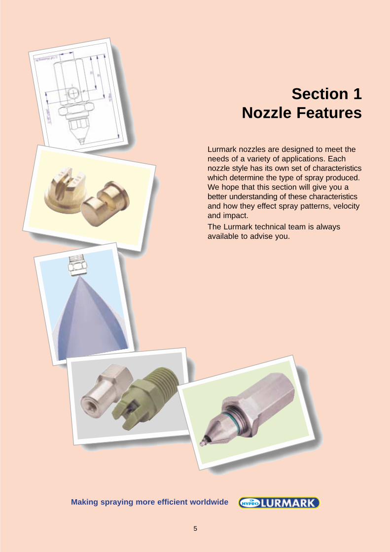
Section 1Nozzle Features
Lurmark nozzles are designed to meet theneeds of a variety of applications. Eachnozzle style has its own set of characteristicswhich determine the type of spray produced.We hope that this section will give you abetter understanding of these characteristicsand how they effect spray patterns, velocityand impact.The Lurmark technical team is always available to advise you.
Making spraying more efficient worldwide
5

CONTROL OF LIQUID FLOWThe flow rate (capacity) ofa fluid through a nozzle isaffected by a number offactors including pressure,specific gravity and viscos-ity of the fluid. PressureAssuming that all factors remain constant, increas-ing pressure will result inan increase in flow througha nozzle. For the majority of industri-al nozzles, this isexpressed as:
Most Lurmark nozzles arecalibrated at 3 bar pres-sure with water, however,should you require the flowrate of a nozzle at a spe-cific pressure, please con-sult us at Lurmark and wewill be happy to calibrateyour nozzle under labora-tory conditions.Movement of the liquidthrough pipe and fittingswill create resistance inthe flow of liquid towardsthe nozzle and as a result,pressure loss will occur.To ensure that the correctpressure is maintained atthe spray tip the pipe mustbe of adequate diameter(see Table 2) and pressurelosses must be taken intoaccount when designingsystems (see page 47).Specific GravityThe specific gravity ordensity of a liquid repre-sents the ratio of a mass
of given volume of liquid tothe mass of the samevolume of water, i.e.:
Generally, the higher the specific gravity of a liquidthe smaller the flow rate ofliquid through the nozzle.The following conversionfactors can be used to calculate specific gravityeffects (Table 1).Table1
Viscosity The viscosity of a liquid isa measure of the extent towhich the liquid resists atendency to flow. In gen-eral, increased pressure is required to atomise moreviscous liquids resulting insprays with a smallerangle compared with wateralone. Nozzle design governs theextent of this effect, but ingeneral, as viscosityincreases, so the flow rateof hollow and full conenozzles is increased and conversely, the flow offlat sprays are decreased.Surface TensionSurface tension is the con-dition existing at the free
surface of a liquid resem-bling the properties of anelastic skin under tension.This tension is a result ofthe intermolecular forcesexerting an unbalancedinward pull on the individ-ual surface molecules.Surface tension affects thedevelopment of the liquidsheet and hence directlyinfluences minimum oper-ating pressures, droplet-size and spray angle assummarised on page 8.TemperatureTemperature influences liquid viscosity, specificgravity and surface ten-sion, and can affect theperformance of spraythrough a nozzle. Datapresented in this hand-book are based on wateronly applications at roomtemperature - for moreextreme conditions, pleaseconsult Lurmark.Atomisation Droplet formation (atomi-sation) begins when a liq-uid is forced through ahydraulic nozzle underpressure so that the liquidforms a thin sheet thatsubsequently breaks-upinto droplets. Each nozzleproduces a range ofdroplet-sizes, known asthe droplet spectra ordrop-size distribution.Droplet-size is measuredin microns (µm).In general, the range ofdroplets produced by anozzle depends on nozzledesign - the smallestdroplets, ideal for applica-tions such as odour controland dust suppression,being produced by airatomising nozzles and the
Q1= Q2 x P1P2
Where Q represents flowrate and P represents
pressure.0.70 0.84 1.200.80 0.89 1.120.90 0.95 1.051.00 1.00 1.001.10 1.05 0.951.20 1.10 0.911.30 1.14 0.881.40 1.18 0.851.50 1.23 0.821.60 1.27 0.791.70 1.30 0.77
1SG √SG √ SG
SG CONVERSION TABLE
LIQUID FLOW = Water flow rate x 1
Spiral Full Cone Flat FanHollow ConeAir Atomising
220
170
150
100
10
RELATIVE DROPLET SIZE BY NOZZLE TYPE
NOZZLE FEATURESSpray nozzles are usedin a wide array of indus-trial applications rang-ing from odour controland dust suppressionthrough to metal paintpre-treatment and fireprotection systems.This extreme versatilityis due to the ability ofthe nozzles to operateover a wide range ofspraying conditions.Nevertheless, whateverthe application, thefunction of the nozzlestill remains the same- to control the flow ofliquid, atomise liquidinto droplets, distrib-ute the droplets in aspecific pattern andgenerate impact over aspecific surface area.The following sectionis a step-by-step guideto the characteristicsof spray nozzles andwill help you select thecorrect nozzle to suityour application. Asummary chart is provided on page 8.
Specific
6

largest, ideal for washingand cleaning being pro-duced by flat fans.There are a number of dif-ferent ways to describedroplet-size information -these are summarised inTable 4. To compare
droplet-size from one nozzle to another, dropletdiameters derived usingthe same assessmentmethod must be used. Should you need specificdroplet-size information,please contact us at
Lurmark - we have adroplet analyser which canbe used to test nozzles.Viscosity and surface ten-sion are the two main fac-tors that influence droplet-size. Generally as viscosi-ty or surface tension isincreased, so the forcesrequired to generatedroplets are increased,leaving less energy avail-able for atomisation. Hence viscous liquids orthose with high surfacetension tend to form morecoarse droplets.Moreover, as flow rateincreases an increase indroplet-size is alsoobserved. In the case ofair atomisers, increasingthe shear velocity of theliquid will decrease dropletsize.Spray PatternThere are a number ofdiferent basic patterns that
can be produced by spraynozzles, as summarisedwith each flow rate chart. Itis more than likely thatmore than one spray pat-tern would meet yourapplication requirements -please consult our techni-cal experts for more infor-mation.Spray angle, coverageand impactUsing trigonometry, the spray angle, measuredclose to the nozzle orifice,and spray distance can beused to calculate the theo-retical area that will becovered by spray (see dia-gram on page 8). In prac-tice, as droplets moveaway from the nozzle ori-fice, they are influenced bygravity and air resistance.As a consequence theactual coverage achievedby a nozzle is substantiallyless than the theoreticalvalue.
Degree of Droplet Size Relative Atomisation (Microns) Size
Fog Up to 20
Fine Mist 20 - 100
Fine Drizzle 100 - 250
Light Rain 250 - 1000
Thunderstorm Rain 1000 - 4000
Table 2 - PRESSURE LOSS OF WATER THROUGH STEELPIPE
FLOWIN
L/min 1/8” 1/4” 3/8” 1/2” 3/4” 1” 1 1/4” 1 1/2” 2” 2 1/2” 3” 3 1/2” 4” 5” 6” 8”
1.0 0.071.5 0.16 0.042.0 0.26 0.062.5 0.40 0.083.0 0.56 0.12 0.03
4.0 0.96 0.21 0.05 0.026.0 2.0 0.45 0.10 0.038.0 3.5 0.74 0.17 0.05 0.01
10.0 - 1.2 0.25 0.08 0.0212.0 - 1.7 0.35 0.11 0.03
15.0 - 2.6 0.54 0.17 0.04 0.0120.0 - - 0.92 0.28 0.07 0.0225.0 - - 1.2 0.45 0.11 0.0330.0 - - 2.1 0.62 0.15 0.04 0.0140.0 - - - 1.1 0.25 0.08 0.02
60.0 - - - - 0.54 0.16 0.04 0.02 0.00680.0 - - - - 0.93 0.28 0.07 0.03 0.009100.0 - - - - - 0.43 0.12 0.05 0.010115.0 - - - - - 0.58 0.14 0.06 0.015130.0 - - - - - 0.72 0.18 0.08 0.02 0.010
150.0 - - - - - - 0.23 0.10 0.03 0.012170.0 - - - - - - 0.29 0.13 0.04 0.016190.0 - - - - - - 0.36 0.16 0.05 0.02230.0 - - - - - - 0.50 0.23 0.07 0.03 0.009260.0 - - - - - - - 0.32 0.09 0.04 0.01
300.0 - - - - - - - 0.38 0.11 0.04 0.02 0.007340.0 - - - - - - - 0.50 0.14 0.06 0.02 0.009380.0 - - - - - - - 0.61 0.18 0.07 0.03 0.01470.0 - - - - - - - - 0.28 0.11 0.04 0.02 0.009570.0 - - - - - - - - 0.39 0.15 0.05 0.03 0.01
750.0 - - - - - - - - 0.64 0.26 0.09 0.04 0.02 0.007950.0 - - - - - - - - - - 0.14 0.06 0.03 0.011150.0 - - - - - - - - - - 0.19 0.09 0.05 0.021500.0 - - - - - - - - - - - 0.16 0.08 0.03 0.011900.0 - - - - - - - - - - - - 0.13 0.04 0.02
2800.0 - - - - - - - - - - - - - 0.09 0.03 0.0093800.0 - - - - - - - - - - - - - 0.16 0.06 0.027500.0 - - - - - - - - - - - - - - 0.23 0.06
PRESSURE DROP IN BAR FOR VARIOUS PIPE SIZES (IN 10 m LENGTH)
Recommended flow rate ranges shown in blue
7

Pressure, viscosity andsurface tension all influ-ence the spray angle.These effects are sum-marised in Table 3.Spray impact can bedescribed as the impinge-ment of spray onto a tar-get surface. Generally, the impact ofdroplets from flat fan,evenspray and straight jetwill be high compared withthose produced from
TABLE 4
deflector, hollow cone andair atomising sprays.Using the formula below,theoretical impact valuecan be obtained.However, both viscosityand pressure will signifi-cantly affect impact(summarised in Tables 3and 5).
The diameter of a droplet whose ratio of volume to surface area is equal tothat of the total sample. This diameter permits the calculation of the totalsurface area of an atomised volume of liquid.
A number which divides the spray into two equal parts by volume.eg A VMD value of 30 microns would mean the spray pattern contains halfthe volume of droplets with diameters of 30 microns and below and halfabove 30 microns.
The average diameter of a drop without reference to volume. The NMDratio reflects the uniformity or span of drop production.
The average of the diameters of all the droplets in the sample.
The diameter of a droplet whose volume if multiplied by the number ofdroplets will equal the total sample volume.
The diameter of a droplet whose surface area if multiplied by the totalnumber of droplets, will equal the total surface area of the sample.
The diameter which divides the surface area of the droplets into two equalhalves
The diameter of a droplet whose ratio of volume to diameter is equal to thatof the entire sample.
Sauter Mean Diameter (SMD). Alsoexpressed as D 32
Volume Median Diameter (VMD).Also known as (MVD) or Dv 0.5,(MMD)
Number Median Diameter (NMD)DN0.5
Arithmetic Mean (D 21)
Volume Mean (D 31)
Surface Mean (D 20)
Surface Median Diameter (D A0.5)
Volume Mean Diameter (D V0.5)
DEFINITIONS OF SOME COMMON SPRAY QUALITY MEASUREMENTS USED WITHIN INDUSTRY
TABLE 3
SUMMARY OF FACTORS AFFECTING
NOZZLE PERFORMANCE
This chart providesa summary of the fac-
tors affecting nozzle per-formance and is applica-
ble to most spraying scenarios.
However, results mayvary for nozzles used
under certain conditions.
Please contact our technical experts for
moreinformation on your specific applications.
PRESSURE SPECIFIC VISCOSITY SURFACE TEMPERATUREINCREASE GRAVITY INCREASE TENSION INCREASE
INCREASE INCREASE
FLOW RATE
FLOW ANGLE
DROPLETSIZE
VELOCITY
IMPACT
WEAR
* NEGLIGIBLE
NEGLIGIBLE
NEGLIGIBLE
NEGLIGIBLE
NEGLIGIBLE
NEGLIGIBLE
NEGLIGIBLE
NEGLIGIBLE
Depends on the spray nozzle used and liquid being sprayed
Full Cone and hollow cone increase, flat fan decreases.
Decrease Increase Depending on nozzle type*
N/cm2 = 0.327 x Flow rate (L/min) x Spraying Pressure (bar)
Spray Spray % ImpactPattern Angle per cm 2 of
Type Degrees TheoreticalTotal Impact*
Flat Fan 15 30%25 18%35 13%40 12%50 10%65 7%80 5%
Full Cone 15 11%30 2.5%50 1%65 0.4%80 0.2%
100 0.1%Hollow Cone 60-80 1-2%
TABLE 5
*30cm distance from nozzle
8
Sprayangle
Actualspray width
Theoretical width

Section 2Spray Nozzles
Selecting the correct nozzle to meet theneeds of your application can help reducecosts, improve productivity and decrease
environmental impact.On the following pages we give details of
the range of Lurmark nozzles and their individual spray characteristics - we hope
that this will help you select the ideal nozzlefor your application.
Making spraying more efficient worldwide
9
APPLICATION NOZZLE SPRAY PAGESERIES TYPE REF
ABSORPTION FN Full Cone 19TN/FCX Full Cone 18
H Hollow Cone 22
APPLICATION Ultra Air Atomising 31OF ADDITIVES Vapro Air Atomising 24
CM Flat Fan 11F Flat Fan 11
HAF/HCX Hollow Cone 22
AERATION H Hollow Cone 22
AGITATION ED Eductor 35CM Flat Fan 11
AIR CONTROL AK Air 32
AIR AND STEAM Ultra Air Atomising 31Vapro Air Atomising 24
AN Flat Fan 12CM Flat Fan 11SN Flat Fan 13
COATING CM Flat Fan 11F Flat Fan 11
COATING TABLETS Ultra Air Atomising 31Vapro Air Atomising 24
COOLING AN Flat Fan 12FN Full Cone 19L Full Cone 19
TN/FCX Full Cone 18HAF/HCX Hollow Cone 22
DISTRIBUTION FN Full Cone 19TOWERS FP Full Cone 18
DUST SUPRESSION AN Flat Fan 12XT Flat Fan 13FN Full Cone 19GN Full Cone 18FP Full Cone 18
TN/FCX Full Cone 18H Hollow Cone 22
HAF/HCX Hollow Cone 22
ETCHING . AN Flat Fan 12(e.g.circuit boards) CM Flat Fan 11
SN Flat Fan 13FN Full Cone 19
APPLICATION NOZZLE SPRAY PAGESERIES TYPE REF
EVAPORATIVE HAF/HCX Misting 22COOLING Ultra Air Atomising 31
Vapro Air Atomising 24
FIRE PROTECTION Ultra Air Atomising 31FN Full Cone 19GN Full Cone 18
FIRE CURTAIN AN Flat Fan 12
FOAM CONTROL AN Flat Fan 12FN Full Cone 19GN Full Cone 19FP Full Cone 18
HUMIDIFICATION Ultra Air Atomising 31Vapro Air Atomising 24
LUBRICATION CM Flat Fan 11(Conveyors)
LUBRICATING Vapro Air Atomising 24(Produce/Product)
METAL FINISHING AN Flat Fan 12CM Flat Fan 11F Flat Fan 11
FN Full Cone 19H Hollow Cone 22
ODOUR CONTROL Ultra Air Atomising 31Vapro Air Atomising 24
TN/FCX Full Cone 18H Hollow Cone 22
HAF/HCX Misting 22
DRY SCRUBBING Ultra Air Atomising 31Vapro Air Atomising 24
SCRUBBING H Hollow Cone 22
SAFETY SHOWERS FN Full Cone 19
TANK WASHING TW Tank Wash 35
WASHING FN Full Cone 19(Intermittent) FP Full Cone 18
TN/FCX Full Cone 18
WASHING CM Flat Fan 11(Surface preparation) HPN Flat Fan 12
SN Flat Fan 13
WASHING AN Flat Fan 12(Conveyor/pre-wet) CM Flat Fan 11
SN Flat Fan 13GN Full Cone 18FP Full Cone 18
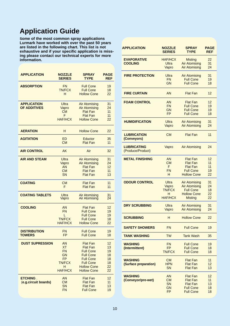
Application GuideSome of the most common spray applicationsLurmark have worked with over the past 50 yearsare listed in the following chart. This list is notexhaustive and if your specific application is miss-ing please contact our technical experts for moreinformation.
10

Flat Fan F Series
TYPICAL APPLICATIONS* Washing e.g. car, gravel* Industrial washing machines* Cleaning e.g. upholstery* Continuous casting* Metal finishing* Degreasing* Foam control* Spray coating* Circuit board processing* Insecticide and herbicide
application
SPRAY CHARACTERISTICS* Available in 0˚, 15˚, 25˚,
40˚, 65˚, 80˚ and 110˚ angles at 3 bar.
* High impact spray of coarsedroplets (greater impact as spray angle decreases).
* Available as evenspray pat-tern for single nozzle appli-cations and as a tapered pattern for use along spray bars (ganging-up) to achieve even distribution.
CONSTRUCTION* Tips are one piece construc
tion, which are fullyinterchangeable.
* Tips have no internal parts,therefore reducing the chance of clogging.
* Tips can be assembled in a 4-piece unit design comprising of nozzle body, strainer tip and cap nut - refer to page 38 for more details.
MATERIALSStandard materials are brass,Acetal and 303 stainlesssteel.
Flat Fan CM Series
TYPICAL APPLICATIONS* Washing e.g. car, gravel,
coal* Industrial washing machines * Cleaning e.g. upholstery* Continuous casting* Metal finishing* Degreasing* Foam control* Spray coating* Circuit board processing
SPRAY CHARACTERISTICS* Available in 0˚, 15˚, 25˚,
40˚, 65˚ 80˚, 90˚ and 110˚ angles at 3 bar.
* High impact spray of coarsedroplets (greater impact asspray angle decreases).
* Available as evenspray pattern for single nozzle applications and as a tapered pattern for use along spray bars (ganging-up) to achieve even distribution.
CONSTRUCTION* One piece male pipe thread
design.* No internal parts, therefore
reducing the chance of clogging.
* Hex body prevents distortion of the orifice for quick and easy installation.
* In areas where space is at apremium, ‘stubby’ versions are available.
MATERIALSStandard materials are brass,PVC and 316 stainless steel.
Flat Fan Fanjet
TYPICAL APPLICATIONS* Washing e.g. car, gravel,
coal* Industrial washing machines * Vegetable washing* Wheel washers* Screen cleaning * Metal finishing* Degreasing* Additive application* Spray coating* Circuit board processing
SPRAY CHARACTERISTICS* Available in 25˚, 40˚, 65˚
and 80˚ angles at 3 bar.* High impact spray of coarsedroplets (greater impact as spray angle decreases).
* Available as evenspray pattern.
CONSTRUCTION* One piece male pipe thread
design.* No internal parts, therefore
reducing the chance of clogging.
* Hex body prevents distortion of the orifice for quick and easy installation.
MATERIALSStandard material is PVDF.
Refer to pages 14 and 15for flow rate charts.
FLAT FANNOZZLES* Special eliptical orificeproduces a narrow elipti-cal spray ‘footprint’. * The droplets are uniform-ly distributed across the‘footprint’ tapering at theedges. * Overlapping these noz-zles by 50% produces aneven spray coverage. Alsoavailable with even ‘foot-prints’ giving a highimpact spray.* Another flat fan patternis produced by deflectornozzles where a straightjet of liquid strikes anaccurately machineddeflector surface produc-ing a wide angle.
Spray Footprints
11
Even
Tapered

Flat Fan AN Series Flanged
TYPICAL APPLICATIONS* Washing e.g. car, gravel,
coal* Film washing* Dish washing * Fire Protection* Foam control* Conveyor belt cooling* Metal cleaning* Water curtains* Pulp and paper processing* Herbicide application
SPRAY CHARACTERISTICS* Available in 90˚ to 145˚
spray angles at 1.5 bar (angle varies with pressure).
* Low impact spray, suitable for use at low pressures.
* Wide spray pattern with uniform distribution.
* Spray deflected 75˚ from inlet orifice.
CONSTRUCTION* Tips are one piece construc
tion, which are fully interchangeable.
* Tips have no internal parts, therefore reducing the chance of clogging.
* Tips can be assembled in a 4-piece unit design compris-ing of nozzle body, filter, tip and cap nut - refer topage 38 for more details.
* Camlock type available in PVDF and Acetal.
MATERIALS* Standard materials arebrass, Acetal and 316 stain-less steel.
Flat Fan AN SeriesThreaded
TYPICAL APPLICATIONS* Washing e.g. car, coal* Film washing* Dish washing* Fire Protection* Foam control* Conveyor belt cooling* Cooling towers (Spraying
eliminator plates)* Metal cleaning* Water curtains* Pulp and paper processing
SPRAY CHARACTERISTICS* Available in 90˚ to 145˚
spray angles at 1.5 bar (angle varies with pressure).
* Low impact spray, suitable for use at low pressures.
* Wide spray pattern with uniform distribution.
* Spray deflected 75˚ from inlet orifice.
CONSTRUCTION* One piece male pipe thread
design.* No internal parts, therefore
reducing the chance of clogging.
* Hex body prevents distortion of the orifice for quick and easy installation.
MATERIALS* Standard materials are
brass, PVC and 316 stainless steel.
Flat Fan HPN Series
TYPICAL APPLICATIONS* High pressure cleaning
applications * Conveyor washing * Animal house disinfection * Building disinfection* Graffiti removal* Descaling * Car washing* Wheel washing* Food processing factories
SPRAY CHARACTERISTICS* Available in 0˚, 15˚, 25˚,
40˚, 50˚, 65˚ spray angles at 10 bar (angle varies with pressure).
* High impact spray producedwith a minimum loss in energy results in high efficiency.
* Overlapping not required.* Even flat spray pattern with
uniform distribution.
CONSTRUCTION* One piece male pipe thread
design.* Hex body prevents distor
tion of the orifice for quick and easy installation.
MATERIALS* Standard material is 416
(hardened) stainless steel.
Refer to pages 14 and 16for flow rate charts.
12

Flat Fan SN Series
TYPICAL APPLICATIONS* Descaling* Washing gravel and stone* Vegetable washing* Vehicle washing* Electronic etch washing* Component washing* Cleaning* Degreasing* Paper mill applications* Garden / show water
features
SPRAY CHARACTERISTICS* Available in 15˚, 25˚, 35˚,
40˚ and 50˚ spray angles at 3 bar (angle varies with pressure).
* High impact, well defined spray with uniform distribution.
CONSTRUCTION* One piece male pipe thread
design, with large round orifice to reduce blockage.
* Deflection plate is precision-machined to maximiseimpact.
MATERIALS* Standard materials are
brass, 303 and 316 stainless steel.
Flat Fan MaxthroXT Series
TYPICAL APPLICATIONS* Spraying waste products* Rangeland and pasture
spraying* Dust suppression* Pesticide application* Road and runway applica-
tions* Fertiliser broadcasting* Where reduced spray drift
required
SPRAY CHARACTERISTICS* Available as 110˚ off-centre
spray.* Off-centre even pattern. * Spray swath width ranges
from 5.18 to 9.45 metres.
CONSTRUCTION* Stainless steel male pipe
thread design.* Patented slotted nozzle
design.
MATERIALS* Standard material is 316
stainless steel and Acetaltip.
Flat Fan C Series
TYPICAL APPLICATIONS* Continuous casting
applications
SPRAY CHARACTERISTICS* Available in 80˚ and 100˚
angle at 3 bar.* Even deflected flat fan pat
tern with an even distribution.
CONSTRUCTION* Three piece design with
internal nozzle to produce aflat fan pattern.
* Fits into a 1” cap nut.Part Number = 28-Q2142.
MATERIALS* Standard material is brass.
Refer to page 14 and 17for flow rate charts.
13
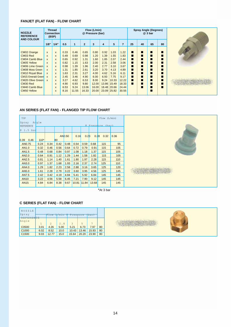
CM02 Orange x x 0.33 0.46 0.65 0.80 0.92 1.03 1.22 ■ ■ ■ ■
CM03 Red x x 0.49 0.69 0.98 1.20 1.39 1.55 1.83 ■ ■ ■ ■
CM04 Camb Blue x x 0.65 0.92 1.31 1.60 1.85 2.07 2.44 ■ ■ ■ ■
CM05 Yellow x x 0.82 1.15 1.63 2.00 2.31 2.58 3.06 ■ ■ ■ ■
CM06 Lime Green x x 0.98 1.39 1.96 2.40 2.77 3.10 3.67 ■ ■ ■ ■
CM08 Moss Green x x 1.31 1.85 2.61 3.20 3.70 4.13 4.89 ■ ■ ■ ■
CM10 Royal Blue x x 1.63 2.31 3.27 4.00 4.62 5.16 6.11 ■ ■ ■ ■
CM15 Emerald Green x x 2.45 3.46 4.90 6.00 6.93 7.75 9.17 ■ ■ ■ ■
CM20 Olive Green x x 3.27 4.62 6.53 8.00 9.24 10.33 12.22 ■ ■ ■ ■
CM30 Red x 4.90 6.93 9.80 12.00 13.86 15.49 18.33 ■ ■ ■ ■
CM40 Camb Blue x 6.53 9.24 13.06 16.00 18.48 20.66 24.44 ■ ■ ■
CM50 Yellow x 8.16 11.55 16.33 20.00 23.09 25.82 30.55 ■
NOZZLEThread Flow (L/min) Spray Angle (Degrees)
REFERENCEConnection @ Pressure (bar) @ 3 bar
AND COLOUR(BSP)
1/8” 1/4” 0.5 1 2 3 4 5 7 25 40 65 80
FANJET (FLAT FAN) - FLOW CHART
AN0.50 0.16 0.23 0.28 0.32 0.360.39 0.46 110* 80
AN0.75 0.24 0.34 0.42 0.48 0.54 0.59 0.68 115 95AN1.0 0.32 0.46 0.56 0.64 0.72 0.79 0.91 115 105AN1.5 0.48 0.68 0.84 0.97 1.08 1.18 1.37 115 105AN2.0 0.64 0.91 1.12 1.29 1.44 1.58 1.82 115 105AN2.5 0.81 1.14 1.40 1.61 1.80 1.97 2.28 115 110AN3.0 0.97 1.37 1.68 1.93 2.16 2.37 2.74 125 110AN4.0 1.29 1.82 2.23 2.58 2.88 3.16 3.65 125 120AN5.0 1.61 2.28 2.79 3.22 3.60 3.95 4.56 125 145AN7.5 2.42 3.42 4.19 4.84 5.41 5.92 6.84 145 145AN10 3.22 4.56 5.58 6.45 7.21 7.90 9.12 145 145AN15 4.84 6.84 8.38 9.67 10.81 11.84 13.68 145 145
AN SERIES (FLAT FAN) - FLANGED TIP FLOW CHART
TIP Flow (L/min)
Spray AngleREFERENCE @ Pressure (bar)
@ 1.5 bar
C SERIES (FLAT FAN) - FLOW CHART
N O Z Z L ESprayREFERENCE
Flow L/min @ Pressure (bar)
Angle1 2 2.8 3 5 7
C0500 3.01 4.26 5.00 5.21 6.73 7.97 80C1000 6.02 8.52 10.0 10.43 13.46 15.93 80C1500 9.03 12.77 15.0 15.64 20.20 23.90 80
*At 3 bar
14

Thread Connection Flow (L/min)(BSP)
@ Pressure (bar)
1/8 ” 1/4 ” 3 /8 ” 1/ 2 ” 3/ 4 ” 1 ” 0.5 1 2 3 4 5 7
1 0 2 0 3 0CM01 X X 0.16 0.23 0.33 0.40 0.46 0.52 0.61 0.73 1.03 1.26
CM015 X X 0.24 0.35 0.49 0.60 0.69 0.77 0.92 1.10 1.55 1.90
CM02 X X 0.33 0.46 0.65 0.80 0.92 1.03 1.22 1.46 2.07 2.53
CM03 X X 0.49 0.69 0.98 1.20 1.39 1.55 1.83 2.19 3.10 3.79
CM04 X X 0.65 0.92 1.31 1.60 1.85 2.07 2.44 2.92 4.13 5.06
CM045 X X 0.73 1.04 1.47 1.80 2.08 2.32 2.75 3.29 4.65 5.69
CM05 X X 0.82 1.15 1.63 2.00 2.31 2.58 3.06 3.65 5.16 6.32
CM055 X X 0.90 1.27 1.80 2.20 2.54 2.84 3.36 4.02 5.68 6.96
CM06 X X 0.98 1.39 1.96 2.40 2.77 3.10 3.67 4.38 6.20 7.59
CM065 X X 1.06 1.50 2.12 2.60 3.00 3.36 3.97 4.75 6.71 8.22
CM07 X X 1.14 1.62 2.29 2.80 3.23 3.61 4.28 5.11 7.23 8.85
CM08 X X 1.31 1.85 2.61 3.20 3.70 4.13 4.89 5.84 8.26 10.12
CM09 X X 1.47 2.08 2.94 3.60 4.16 4.65 5.50 6.57 9.30 11.38
CM10 X X 1.63 2.31 3.27 4.00 4.62 5.16 6.11 7.30 10.33 12.65
CM15 X X 2.45 3.46 4.90 6.00 6.93 7.75 9.17 10.95 15.49 18.97
CM20 X X 3.27 4.62 6.53 8.00 9.24 10.33 12.22 14.61 20.66 25.30
CM30 X 4.90 6.93 9.80 12.00 13.86 15.49 18.33 21.91 30.98 37.95
CM40 X X 6.53 9.24 13.06 16.00 18.48 20.66 24.44 29.21 41.31 50.60
CM50 X X 8.16 11.55 16.33 20.00 23.09 25.82 30.55 36.51 51.64 63.25
CM60 X X 9.80 13.86 19.60 24.00 27.71 30.98 36.66 43.82 61.97 75.89
CM70 X X 11.43 16.17 22.86 28.00 32.33 36.15 42.77 51.12 72.30 88.54
CM80 X X 13.06 18.48 26.13 32.00 36.95 41.31 48.88 58.42 82.62 101.19
CM100 X X X 16.33 23.09 32.66 40.00 46.19 51.64 61.10 73.03 103.28 126.49
CM150 X X 24.49 34.64 48.99 60.00 69.28 77.46 91.65 109.54 154.92 189.74
CM200 X X 32.66 46.19 65.32 80.00 92.38 103.28 122.20 146.06 206.56 252.98
CM250 X 40.82 57.74 81.65 100.00 115.47 129.10 152.75 182.57 258.20 316.23
CM300 X X 48.99 69.28 97.98 120.00 138.56 154.92 183.30 219.09 309.84 379.47
CM400 X X 65.32 92.38 130.64 160.00 184.75 206.56 244.40 292.12 413.12 505.96
N O Z Z L EREFERE
CM SERIES (FLAT FAN) - FLOW CHART
TIP REFERENCE Flow (L/min)
Tapered Evenspray@ Pressure (bar)
0.5 1 2 3 4 57 10 20 3 0
005F 005E 0.08 0.12 0.16 0.20 0.23 0.26 0.31 0.37 0.52 0.63
0067F 0067E 0.11 0.15 0.22 0.27 0.31 0.35 0.41 0.49 0.69 0.85
0077F 0077E 0.13 0.18 0.25 0.31 0.36 0.40 0.47 0.56 0.80 0.97
01F 01E 0.16 0.23 0.33 0.40 0.46 0.52 0.61 0.73 1.03 1.26
015F 015E 0.24 0.35 0.49 0.60 0.69 0.77 0.92 1.10 1.55 1.90
02F 02E 0.33 0.46 0.65 0.80 0.92 1.03 1.22 1.46 2.07 2.53
03F 03E 0.49 0.69 0.98 1.20 1.39 1.55 1.83 2.19 3.10 3.79
04F 04E 0.65 0.92 1.31 1.60 1.85 2.07 2.44 2.92 4.13 5.06
05F 05E 0.82 1.15 1.63 2.00 2.31 2.58 3.06 3.65 5.16 6.32
06F 06E 0.98 1.39 1.96 2.40 2.77 3.10 3.67 4.38 6.20 7.59
08F 08E 1.31 1.85 2.61 3.20 3.70 4.13 4.89 5.84 8.26 10.12
10F 10E 1.63 2.31 3.27 4.00 4.62 5.16 6.11 7.30 10.33 12.65
15F 15E 2.45 3.46 4.90 6.00 6.93 7.75 9.17 10.95 15.49 18.97
F SERIES (FLAT FAN) - FLOW CHART
15

AN0.50 x 0.16 0.23 0.28 0.32 0.36 0.39 0..46 110*
AN0.80 x 0.24 0.34 0.42 0.48 0.54 0.59 0.68 115
AN1.0 x 0.32 0.46 0.56 0.64 0.72 0.79 0.91 115
AN1.5 x 0.48 0.68 0.84 0.97 1.08 1.18 1.37 115
AN2.0 x x 0.64 0.91 1.12 1.29 1.44 1.58 1.82 115
AN2.5 x x 0.81 1.14 1.40 1.61 1.80 1.97 2.28 115
AN3.0 x x 0.97 1.37 1.68 1.93 2.16 2.37 2.74 125
AN4.0 x x 1.29 1.82 2.23 2.58 2.88 3.16 3.65 125
AN5.0 x x 1.61 2.28 2.79 3.22 3.60 3.95 4.56 125
AN7.5 x x 2.42 3.42 4.19 4.84 5.41 5.92 6.84 145
AN10 x x 3.22 4.56 5.58 6.45 7.21 7.90 9.12 145
AN15 x x 4.84 6.84 8.38 9.67 10.81 11.84 13.68 145
AN20 x x x 6.45 9.12 11.17 12.89 14.42 15.79 18.24 145
AN25 x x 8.06 11.40 13.96 16.12 18.02 19.74 22.79 145
AN30 x 9.67 13.68 16.75 19.34 21.62 23.69 27.35 145
AN35 x 11.28 15.96 19.54. 22.57 25.23 27.64 31.91 145
AN40 x x 12.89 18.24 22.33 25.79 28.83 31.58 36.47 145
AN50 x 16.12 22.79 27.92 32.24 36.04 39.48 45.59 145
AN60 x x 19.34 27.35 33.50 38.68 43.25 47.38 54.71 145
AN80 x x 25.79 36.47 44.67 51.58 57.67 63.17 72.94 145
AN100 X x 32.24 45.59 55.83 64.47 72.08 78.96 91.18 145
AN120 x 38.68 54.71 67.00 77.37 86.50 94.75 109.41 145
AN160 x 51.58 72.94 89.33 103.15 115.33 126.34 145.88 145
AN210 x 67.70 95.74 117.25 135.39 151.37 165.82 191.47 145
AN300 x 96.71 136.76 167.50 193.41 216.24 236.88 273.53 145
AN450 x 145.06 205.15 251.25 290.12 324.37 355.33 410.29 145
N O Z Z L EREFERENCE
Connection Flow(L/min)
(BSP) @ Pressure (bar)
1/8 ” 1/4 ” 1 5 2 0 3 0 4 0 5 0 6 0 8 0 1 0 0 1 5 0 2 0 0HPN 04 x x 3.46 4.00 4.90 5.66 6.32 6.93 8.00 8.94 10.95 12.65
HPN 045 x x 3.90 4.50 5.51 6.36 7.12 7.79 9.00 10.06 12.32 14.23
HPN 05 x x 4.33 5.00 6.12 7.07 7.91 8.66 10.00 11.18 13.69 15.81
HPN 055 x x 4.76 5.50 6.74 7.78 8.70 9.53 11.00 12.30 15.06 17.39
HPN 06 x x 5.20 6.00 7.35 8.49 9.49 10.39 12.00 13.42 16.43 18.97
HPN 065 x x 5.63 6.50 7.96 9.19 10.28 11.26 13.00 14.53 17.80 20.55
HPN 07 x x 6.06 7.00 8.57 9.90 11.07 12.12 14.00 15.65 19.17 22.14
HPN 075 x x 6.50 7.50 9.19 10.61 11.86 12.99 15.00 16.77 20.54 23.72
HPN 08 x x 6.93 8.00 9.80 11.31 12.65 13.86 16.00 17.89 21.91 25.30
HPN 085 x x 7.36 8.50 10.41 12.02 13.44 14.72 17.00 19.01 23.28 26.88
HPN 09 x x 7.79 9.00 11.02 12.73 14.23 15.59 18.00 20.12 24.65 28.46
HPN 10 x x 8.66 10.00 12.25 14.14 15.81 17.32 20.00 22.36 27.39 31.62
HPN 15 x x 12.99 15.00 18.37 21.21 23.72 25.98 30.00 33.54 41.08 47.43
HPN 20 x x 17.32 20.00 24.49 28.28 31.62 34.64 40.00 44.72 54.77 63.25
HPN 30 x 25.98 30.00 36.74 42.43 47.43 51.96 60.00 67.08 82.16 94.87
HPN 40 x 34.64 40.00 48.99 56.57 63.25 69.28 80.00 89.44 109.54 126.49
NOZZLE Thread ConnectionFlow (L/min) SprayREFERENCE B S P@ Pressure (bar) Angle
@
HPN SERIES (FLAT FAN) - FLOW CHART
AN SERIES - THREADED (FLAT FAN) - FLOW CHART
*At 3 bar
Items against white background available from stock
16

Flow(L/min) @ Operating Pressure (bar)
1/8” 1/4” 3/8” 1/2” 3/4” 1 2 3 4 5 7
10 15 35 50
SN 4 x 0.91 1.29 1.58 1.82 2.04 2.4 2.88
x
SN 10 x 2.28 3.22 3.95 4.56 5.10 6.03 7.21 x x x
SN 20 x x 4.56 6.45 7.90 9.12 10.19 12.06 14.42 x x
SN 25 x 5.70 8.06 9.87 11.40 12.74 15.08 18.02 x
SN 40 x 9.12 12.89 15.79 18.24 20.39 24.12 28.83 x x x
SN 50 x 11.40 16.12 19.74 22.79 25.48 30.15 36.04 x
SN 60 x x 13.68 19.34 23.69 27.35 39.58 36.18 43.25 x x x
SN 80 x 18.24 25.79 31.58 36.47 40.78 48.25 57.67 x
SN 100 x x 22.79 32.24 39.48 45.59 50.97 60.31 72.08 x
N O Z Z L E
REFEREN
SN SERIES (FLAT FAN) - FLOW CHART
Maxthro XT SERIES (FLAT FAN) - FLOW CHART
NOZZLE Thread Connection (NPT) Flow (L/min) @ Pressure (bar)Swath Width (m) REF 1/4” 3/8” 1/2” 3/4” 1” 3 4 5
XT020 x 7.90 9.12 10.19 5.18XT024 x 9.48 10.94 12.23 5.18 XT043 x 16.98 19.60 21.92 6.10XT080 x 31.58 36.47 40.77 6.40XT167 x 65.93 76.13 85.12 9.45XT215 x 84.88 98.01 109.58 9.45XT330 x 130.28 150.44 168.196 6.40
ThreadConnection (BSP)
Spray Angle @ 3 bar
17
FullConeFCX andTN Series
TYPICAL APPLICATIONS* Spray rinsing* Foam control* Strand cooling* Industrial washing machines* Vegetable washing* Dust suppression* Gas scrubbing* Fire protection* Odour control* Chemical processing
SPRAY CHARACTERISTICS* Available in 70˚, 80˚ and
110˚ angles at 3 bar (angle may vary with pressure).
* Medium impact spray, impact greater with narrow spray angles.
* Full cone spray pattern withuniform distribution.
CONSTRUCTION* All tips are fully inter-
changeable.* Tips have an internal swirl
core to generate a full conepattern.
* Tips can be assembled in a4-piece unit design compris-ing of nozzle body, filter, tip and cap nut - refer to page 38 for more details.
MATERIALS* Standard materials are
brass, acetal and 316 stainless steel.
Full ConeFP Series
FULLCO
TYPICAL APPLICATIONS* Extrusion cooling* Industrial washing machines* Gravel washing* Vegetable cleaning* Surface spraying* Dust suppression* Food processing* Foam control* Gas Scrubbing
SPRAY CHARACTERISTICS* Available in 45˚ to 120˚
angles at 3 bar (angle may vary with pressure).
* Low impact spray.* Full cone spray pattern with
uniform distribution.* No overlapping required.
CONSTRUCTION* All tips are fully inter-
changeable.* Fixed internal impeller cre-
ates a liquid swirl, whichgenerates a full cone pattern.
* Hex body prevents distortionof the orifice for quick and easy installation.
MATERIALS* Standard material is PVDF.
Full ConeGN Series
TYPICAL APPLICATIONS* Fire protection* Industrial washing machines* Gas scrubbing* Gas conditioners* Vegetable cleaning* Gravel washing* Spray cooling* Foam control* Dust suppression
SPRAY CHARACTERISTICS* Available in 50˚ and 120˚
angles at 3 bar (angle varieswith pressure).
* Medium impact spray of fine/medium droplets. (greater impact as spray angle decreases).
* Full cone pattern of uniformlydistributed droplets.
* Square pattern available on request.
CONSTRUCTION* Two piece nozzle body with
removable internal swirl core to produce full cone pattern.
* Right angled design* Square body for quick and
easy installation.
MATERIALS* Standard material is brass.
Refer to page 20 for flowrate chart
FULL CONENOZZLES* Spray generated in a similar manner to the hollow cone but is balanced by an axialliquid component mixing within the swirlchamber to fill in thecone. * Medium impact can beobtained.
Spray Footprints
18
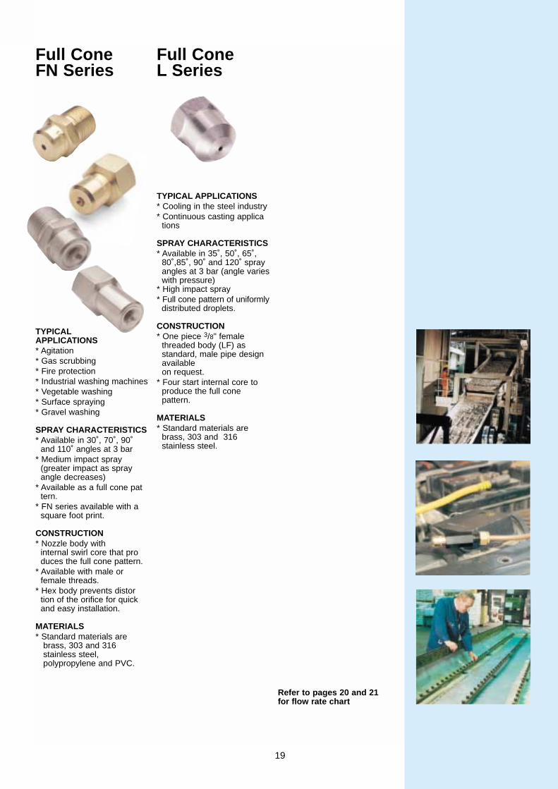
Full ConeFN Series
TYPICALAPPLICATIONS* Agitation* Gas scrubbing* Fire protection* Industrial washing machines* Vegetable washing* Surface spraying* Gravel washing
SPRAY CHARACTERISTICS* Available in 30˚, 70˚, 90˚
and 110˚ angles at 3 bar* Medium impact spray
(greater impact as spray angle decreases)
* Available as a full cone pattern.
* FN series available with asquare foot print.
CONSTRUCTION* Nozzle body with
internal swirl core that produces the full cone pattern.
* Available with male or female threads.
* Hex body prevents distortion of the orifice for quick and easy installation.
MATERIALS* Standard materials are
brass, 303 and 316 stainless steel,polypropylene and PVC.
Full Cone L Series
TYPICAL APPLICATIONS* Cooling in the steel industry* Continuous casting applica
tions
SPRAY CHARACTERISTICS* Available in 35˚, 50˚, 65˚,
80˚,85˚, 90˚ and 120˚ spray angles at 3 bar (angle varieswith pressure)
* High impact spray* Full cone pattern of uniformly
distributed droplets.
CONSTRUCTION* One piece 3/8" female
threaded body (LF) as standard, male pipe designavailable on request.
* Four start internal core to produce the full cone pattern.
MATERIALS* Standard materials are
brass, 303 and 316 stainless steel.
Refer to pages 20 and 21for flow rate chart
19

FCX AND TN SERIES (FULL CONE) - FLOW CHART
L SERIES (FULL CONE) - FLOW CHART
FP SERIES (FULL CONE) - FLOW CHART
TIP REFERENCES Flow (L/min) Spray Angle @ 3 bar
@ Pressure (bar) Standard Wide
Tip Tip METAL ACETAL 1 2 3 4 5 7 10
TN1 0.46 0.64 0.79 0.91 1.02 1.21 1.44 70 -FCX02 0.74 1.05 1.29 1.49 1.66 1.97 2.35 80 -
TN2 0.91 1.29 1.58 1.82 2.04 2.41 2.88 70 110FCX03 1.12 1.58 1.93 2.23 2.50 2.95 3.53 80 -
TN3 1.37 1.93 2.37 2.74 3.06 3.62 4.32 70 110FCX04 1.49 2.11 2.58 2.98 3.33 3.94 4.71 80 -
TN3.5 1.60 2.26 2.76 3.19 3.57 4.22 5.06 70 110FCX05 1.86 2.63 3.22 3.72 4.16 4.92 5.89 80 -
TN5 2.28 3.22 3.95 4.56 5.10 6.03 7.21 70 110FCX06 2.23 3.16 3.87 4.47 4.99 5.91 7.06 80 -
TN6.5 2.96 4.19 5.13 5.93 6.63 7.84 9.37 70 110FCX08 2.98 4.21 5.16 5.96 6.66 7.88 9.42 80 -
TN10 4.56 6.45 7.90 9.12 10.19 12.06 14.42 70 110TN12 5.47 7.74 9.48 10.94 12.23 14.47 17.30 70 110
NOZZLE Colour
Thread Flow (L/min)
Spray
REFConnections Angle
(BSP) @ Pressure (bar) @ 1 bar1/8” 1/4” 0.5 1 2 3 4 5 7 10
FP1 Orange x 0.32 0.46 0.64 0.79 0.91 1.02 1.21 1.44 45FP1.3W Natural x 0.42 0.59 0.84 1.03 1.19 1.33 1.57 1.87 90FP1.5 Red x 0.48 0.68 0.97 1.18 1.37 1.53 1.81 2.16 55FP2 Camb Blue x 0.64 0.91 1.29 1.58 1.82 2.04 2.41 2.88 60FP2W Camb Blue x 0.64 0.91 1.29 1.58 1.82 2.04 2.41 2.88 90FP3 Lime Green x 0.97 1.37 1.93 2.37 2.74 3.06 3.62 4.32 50FP3.5 Terracota x 1.13 1.60 2.26 2.76 3.19 3.57 4.22 5.05 60FP3.7W Grey x 1.19 1.69 2.39 2.92 3.37 3.77 4.46 5.33 120FP5 Royal Blue x 1.61 2.28 3.22 3.95 4.56 5.10 6.03 7.21 80FP6.5 Purple x 2.10 2.96 4.19 5.13 5.93 6.63 7.84 9.37 50FP10 Olive Green x3.22 4.56 6.45 7.90 9.12 10.19 12.06 14.42 70
NOZZLE Flow (L/min) @ Pressure barREFERENCE 1.0 2.8 3.0 4.0 5.0 7.0
L15 0.90 1.50 1.56 1.81 2.02 2.39L20 1.20 2.00 2.09 2.41 2.69 3.19L25 1.51 2.50 2.61 3.01 3.37 3.98L30 1.81 3.00 3.13 3.61 4.04 4.78L35 2.11 3.50 3.65 4.22 4.71 5.58L38 2.29 3.80 3.96 4.58 5.12 6.05L40 2.41 4.00 4.17 4.82 5.39 6.37L45 2.71 4.50 4.69 5.42 6.06 7.17L50 3.01 5.00 5.21 6.02 6.73 7.97L55 3.31 5.50 5.74 6.62 7.41 8.76L60 3.61 6.00 6.26 7.23 8.08 9.56L70 4.22 7.00 7.30 8.43 9.43 11.15L75 4.52 7.50 7.82 9.03 10.10 11.95L80 4.82 8.00 8.34 9.63 10.77 12.75L85 5.12 8.50 8.87 10.24 11.44 13.54L90 5.42 9.00 9.39 10.84 12.12 14.34L120 7.23 12.00 12.52 14.45 16.16 19.12L137 8.25 13.71 14.29 16.50 18.45 21.83
GN SERIES (FULL CONE) - FLOW CHART
NOZZLE Thread connections Flow (L/min) Spray
REFERENCE (BSP) @ Pressure (bar) A ngle
@3 bar1/8” 1/4” 3/8” 1 2 3 4 5 7 10
GN2 X 0.91 1.29 1.58 1.82 2.04 2.41 2.88 50GN3 X 1.37 1.93 2.37 2.74 3.06 3.62 4.32 65GN3.9 X 1.78 2.51 3.08 3.56 3.98 4.70 5.62 84GN4.3 X 1.96 2.77 3.40 3.92 4.38 5.19 6.20 120GN5 X 2.28 3.22 3.95 4.56 5.10 6.03 7.21 65GN6.5 X 2.96 4.19 5.13 5.93 6.63 7.84 9.37 50GN8 X 3.65 5.16 6.32 7.29 8.16 9.65 11.53 120GN10 X 4.56 6.45 7.90 9.12 10.19 12.06 14.42 67GN12.5 X 5.70 8.06 9.87 11.40 12.74 15.08 18.02 74GN14 X 6.38 9.03 11.05 12.76 14.27 16.89 20.18 120GN15 X 6.84 9.67 11.84 13.68 15.29 18.09 21.62 67GN20 X 9.12 12.89 15.79 18.24 20.39 24.12 28.83 120
20

FN SERIES (FULL CONE) - FLOW CHART
NOZZLE Thread Connection (BSP) Flow (L/min) @ Operating Presure (bar) Spray Angle (Degrees)
REFERENCE @ 3 bar1/8” 1/4” 3/8” 1/2” 3/4” 1” 0.5 1 2 3 4 5 7 10 30 70 90 110
FN0.8 x 0.33 0.46 0.65 0.80 0.92 1.03 1.22 1.46 x xFN1.0 x x 0.41 0.58 0.82 1.00 1.15 1.29 1.53 1.83 xFN1.2 x x 0.49 0.69 0.98 1.20 1.39 1.55 1.83 2.19 x xFN1.6 x x 0.65 0.92 1.31 1.60 1.85 2.07 2.44 2.92 x xFN2.0 x x 0.82 1.15 1.63 2.00 2.31 2.58 3.06 3.65 xFN2.4 x x 0.98 1.39 1.96 2.40 2.77 3.10 3.67 4.38 x xFN3.2 x x 1.31 1.85 2.61 3.20 3.70 4.13 4.89 5.84 x xFN4.0 x x 1.63 2.31 3.27 4.00 4.62 5.16 6.11 7.30 x x xFN5.0 x 2.04 2.89 4.08 5.00 5.77 6.45 7.64 9.13 xFN5.1 x x 2.08 2.94 4.16 5.10 5.89 6.58 7.79 9.31 x xFN6.3 x x 2.57 3.64 5.14 6.30 7.27 8.13 9.62 11.50 x xFN7.3 x 2.98 4.21 5.96 7.30 8.43 9.42 11.15 13.33 xFN9.5 x 3.88 5.48 7.76 9.50 10.97 12.26 14.51 17.34 x xFN10.0 x 4.08 5.77 8.16 10.00 11.55 12.91 15.28 18.26 xFN11.0 x 4.49 6.35 8.98 11.00 12.70 14.20 16.80 20.08 xFN12.0 x x 4.90 6.93 9.80 12.00 13.86 15.49 18.33 21.91 x xFN17.0 x x 6.94 9.81 13.88 17.00 19.63 21.95 25.97 31.04 x xFN19.0 x x 7.76 10.97 15.51 19.00 21.94 24.53 29.02 34.69 x xFN20.0 x 8.16 11.55 16.33 20.00 23.09 25.82 30.55 36.51 xFN22.0 x 8.98 12.70 17.96 22.00 25.40 28.40 33.61 40.17 xFN24.0 x x 9.80 13.86 19.60 24.00 27.71 30.98 36.66 43.82 x xFN30.0 x x 12.25 17.32 24.49 30.00 34.64 38.73 45.83 54.77 x xFN37.0 x x 15.11 21.36 30.21 37.00 42.72 47.77 56.52 67.55 x x xFN43.0 x x 17.55 24.83 35.11 43.00 49.65 55.51 65.68 78.51 xFN45.0 x x 18.37 25.98 36.74 45.00 51.96 58.09 68.74 82.16 xFN47.0 x x 19.19 27.14 38.38 47.00 54.27 60.68 71.79 85.81 x xFN60.0 x x 24.49 34.64 48.99 60.00 69.28 77.46 91.65 109.54 xFN71.0 x x 28.99 40.99 57.97 71.00 81.98 91.66 108.45 129.63 x xFN90.0 x 36.74 51.96 73.48 90.00 103.92 116.19 137.48 164.32FN118.0 x 48.17 68.13 96.35 118.00 136.25 152.34 180.25 215.44 x xFN150.0 x 61.24 86.60 122.47 150.00 173.21 193.65 229.13 273.86 x x
21

Hollow ConeHAF and HCXSeries
TYPICAL APPLICATIONS* Humidification* Evaporative cooling* Odour control* Gas scrubbing* Gas cooling* Insecticide spraying* Spray drying* Filter cage washing* Dust suppression* Fire protection
SPRAY CHARACTERISTICS* Available in 80˚ angle at 3
bar (angle may vary with pressure)
* Low impact spray of fine droplets
* Hollow cone spray pattern
CONSTRUCTION* All tips are fully inter
changeable.* Tips can be assembled in a
4-piece unit design compris-ing of nozzle body, filter, tip and cap nut - refer to page 38 for more details.
MATERIALS* Standard materials are
brass, Acetal and 316 stainless steel.
Hollow ConeMisting Nozzle Series
TYPICAL APPLICATIONS* Humidification* Evaporative cooling* Odour control* Dust suppression* Gas cooling* Cooling areas* Insecticide spraying* Disinfectant applications* Fire protection
SPRAY CHARACTERISTICS* Threaded version is avail
able in 80˚, 100˚ and 105˚ angle at 3 bar
* Tip version is available in 70˚ to 110˚ angle at 3 bar
* Very low impact spray of extremely fine droplets (VMD ca 50 µm)
* Hollow cone spray pattern * Ball check version available
in threaded design.
CONSTRUCTION* Two piece design in flanged
tip or 1/8" threaded design* Optional push-fit porous fil
ter manufactured in poly-ethylene available on request. This is designed to filterdown to 50µm. Please quote part number 32195Q3269.
MATERIAL* Standard material is Acetal.
Hollow ConeH Series
TYPICAL APPLICATIONS* Aeration * Cooling towers* Gas scrubbing* Degreasing* Dust suppression* Humidification* Roof cooling* Evaporative coolers* Metal pre-treatment* Brine spraying
SPRAY CHARACTERISTICS* Available in 70˚ or 110˚
angle at 3 bar * Low impact spray of fine
droplets * Hollow cone spray pattern
CONSTRUCTION* Two piece design with no
internal parts, hence less likely to block. The swirl chamber is designed with anevenly tapered bottom to prevent erosion from liquid.
* Right angled spray* Square body for easy
installation
MATERIALS* Standard materials are
brass, 316 stainless steel, PVC, polypropylene.
Refer to page 23 for flow rate chart
HOLLOWCONE NOZZLESA circular ring of liquidis formed when liquid ischanelled by a tangen-tial flow path whichcauses swirl and atomi-sation into a hollowcone pattern.
Spray Footprint
22
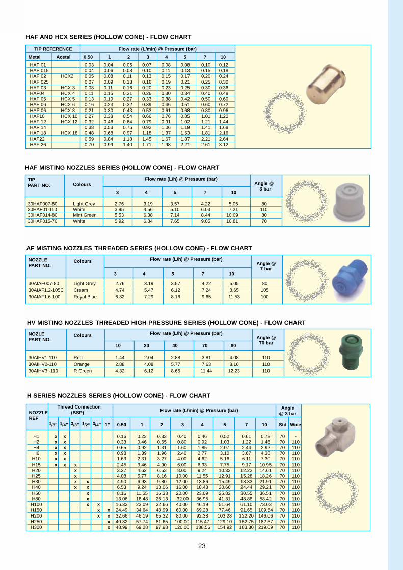
HAF AND HCX SERIES (HOLLOW CONE) - FLOW CHART
HAF MISTING NOZZLES SERIES (HOLLOW CONE) - FLOW CHART
AF MISTING NOZZLES THREADED SERIES (HOLLOW CONE) - FLOW CHART
HV MISTING NOZZLES THREADED HIGH PRESSURE SERIES (HOLLOW CONE) - FLOW CHART
TIP REFERENCE Flow rate (L/min) @ Pressure (bar)
Metal Acetal 0.50 1 2 3 4 5 7 10
HAF 01 0.03 0.04 0.05 0.07 0.08 0.08 0.10 0.12HAF 015 0.04 0.06 0.08 0.10 0.11 0.13 0.15 0.18HAF 02 HCX2 0.05 0.08 0.11 0.13 0.15 0.17 0.20 0.24HAF 025 0.07 0.09 0.13 0.16 0.19 0.21 0.25 0.30HAF 03 HCX 3 0.08 0.11 0.16 0.20 0.23 0.25 0.30 0.36HAF04 HCX 4 0.11 0.15 0.21 0.26 0.30 0.34 0.40 0.48HAF 05 HCX 5 0.13 0.19 0.27 0.33 0.38 0.42 0.50 0.60HAF 06 HCX 6 0.16 0.23 0.32 0.39 0.46 0.51 0.60 0.72HAF 06 HCX 8 0.21 0.30 0.43 0.53 0.61 0.68 0.80 0.96HAF10 HCX 10 0.27 0.38 0.54 0.66 0.76 0.85 1.01 1.20HAF 12 HCX 12 0.32 0.46 0.64 0.79 0.91 1.02 1.21 1.44HAF 14 0.38 0.53 0.75 0.92 1.06 1.19 1.41 1.68HAF 18 HCX 18 0.48 0.68 0.97 1.18 1.37 1.53 1.81 2.16HAF22 0.59 0.84 1.18 1.45 1.67 1.87 2.21 2.64HAF 26 0.70 0.99 1.40 1.71 1.98 2.21 2.61 3.12
TIPColours
Flow rate (L/h) @ Pressure (bar)PART NO. Angle @
3 4 5 7 103 bar
30HAF007-80 Light Grey 2.76 3.19 3.57 4.22 5.05 8030HAF01-110 White 3.95 4.56 5.10 6.03 7.21 11030HAF014-80 Mint Green 5.53 6.38 7.14 8.44 10.09 8030HAF015-70 White 5.92 6.84 7.65 9.05 10.81 70
NOZZLE Colours Flow rate (L/h) @ Pressure (bar)PART NO. Angle @
3 4 5 7 10 7 bar
30AIAF007-80 Light Grey 2.76 3.19 3.57 4.22 5.05 8030AIAF1.2-105C Cream 4.74 5.47 6.12 7.24 8.65 10530AIAF1.6-100 Royal Blue 6.32 7.29 8.16 9.65 11.53 100
NOZLE Colours Flow rate (L/h) @ Pressure (bar)PART NO. Angle @
10 20 40 70 80 70 bar
30AIHV1-110 Red 1.44 2.04 2.88 3.81 4.08 11030AIHV2-110 Orange 2.88 4.08 5.77 7.63 8.16 11030AIHV3 -110 R Green 4.32 6.12 8.65 11.44 12.23 110
Thread Connection Flow rate (L/min) @ Pressure (bar)NOZZLE (BSP)
REF1/8” 1/4” 3/8” 1/2” 3/4” 1” 0.50 1 2 3 4 5 7 10 Std Wide
H1 x x 0.16 0.23 0.33 0.40 0.46 0.52 0.61 0.73 70 -H2 x x 0.33 0.46 0.65 0.80 0.92 1.03 1.22 1.46 70 110H4 x x 0.65 0.92 1.31 1.60 1.85 2.07 2.44 2.92 70 110H6 x x 0.98 1.39 1.96 2.40 2.77 3.10 3.67 4.38 70 110
H10 x x 1.63 2.31 3.27 4.00 4.62 5.16 6.11 7.30 70 110H15 x x x 2.45 3.46 4.90 6.00 6.93 7.75 9.17 10.95 70 110H20 x 3.27 4.62 6.53 8.00 9.24 10.33 12.22 14.61 70 110H25 x 4.08 5.77 8.16 10.00 11.55 12.91 15.28 18.26 70 110H30 x x 4.90 6.93 9.80 12.00 13.86 15.49 18.33 21.91 70 110H40 x x 6.53 9.24 13.06 16.00 18.48 20.66 24.44 29.21 70 110H50 x 8.16 11.55 16.33 20.00 23.09 25.82 30.55 36.51 70 110H80 x 13.06 18.48 26.13 32.00 36.95 41.31 48.88 58.42 70 110
H100 x x 16.33 23.09 32.66 40.00 46.19 51.64 61.10 73.03 70 110H150 x x 24.49 34.64 48.99 60.00 69.28 77.46 91.65 109.54 70 110H200 x x 32.66 46.19 65.32 80.00 92.38 103.28 122.20 146.06 70 110H250 x 40.82 57.74 81.65 100.00 115.47 129.10 152.75 182.57 70 110H300 x 48.99 69.28 97.98 120.00 138.56 154.92 183.30 219.09 70 110
H SERIES NOZZLES SERIES (HOLLOW CONE) - FLOW CHART
Angle @ 3 bar
23

Vapro SeriesVery fine droplets are pro-duced by a simple shearingaction when liquid and airstreams meet, internally orexternally to the VAPRO nozzle. A wide range ofspray patterns are availableto suit your application.
TYPICAL APPLICATIONS* Odour control* Application of additives* Air and steam processing* Coating* Tablet coating* Fire protection* Humidification* Dry scrubbing* Lubricating products
SPRAY CHARACTERISTICS* Low impact spray of veryfine droplets (typically lessthan 100µm diameter)* Flat fan, full cone fog pat-terns available.* Spray droplets are generat-ed internal or external to thenozzle:
Internal Mix: Liquid and airmix together and are expelledthrough one nozzle orifice.After mixing, the air and liquidare combined making precisemetering of the liquid difficulti.e. changes in airflow willaffect the liquid flow. Finedroplets are producedfrom this set-up than from theexternal mix.
External mix: Liquid and airare expelled independentlyand are mixed externally tothe nozzle. Hence, air andliquid flow rates can be con-trolled independently.External mixes are ideal forapplications where abrasivesuspensions or liquids withviscosities over 200 centi-poises.
CONSTRUCTION* The VAPRO assembly con-sists of a body, air and liquidnozzle combination andscrew cap. Additional hard
ware can provide automatedshut-off and clean-out facili-ties.Body: Available as standard,non-automatic, square body(code: VP) or complete with abuilt-in pneumatic cylinderwith single (code: VPX) ordual air inlets (code: VPL).Shut-off and clean-out optionsavailable on all models onrequest.
OPTIONSAutomatic shut-off. Built-inpneumatic cylinder is con-nected to a needle, whichopens and closes the liquidorifice on command. Thisoption offers positive shut-offwith no dripping. Whenused in systems, it is impor-tant to remember that VAPROnozzles require a minimumoperating pressure of 2 bar.
Clean-out needle . Appliedpressure to the spring-loadedplunger forces a small diameter rod through the liquid orifice to remove anyobstructions.
Thin and thick-walled adaptors . Available formounting nozzles on duct-work and bulkheads of vary-ing thickness available onrequest.
Air and Liquid nozzles . Acomplete spray set-up con-sists of an air nozzle and aliquid nozzle. To create thedesired flow rate and spraypattern, the fully interchange-able air and liquid caps should be selected according
to the flow tables (Pages 25-30).
Screw cap. Comes with com-plete assembly.
NOZZLE FEEDINGVAPRO nozzles can be usedin systems where the liquid iseither fed to the nozzle from a pump under pressure orobtained under siphon feed.
Pressure configuration. Idealfor use in most applications with a variety of spray pat-terns and flow rates. At aknown liquid pressure,air pressure can be adjusteduntil the optimum flow rateand droplet-sizes areachieved. For the internalmix increasing the air pres-sure will reduce liquid flowand so produce more finedroplets.
Siphon configuration. Thisconfiguration allows for sim-ple system development todeliver low flow rates. Thesame air pressure adjust-ments as for pressure config-urations can be made; more-over, the liquid flow rate canbe adjusted based on theheight of the liquid container.
MATERIALS* Standard material for com-plete assembly is 316 stainless steel.* Standard materials for sealsare Teflon and Viton.* Please contact our technicalexperts for more informationregarding materials.
Refer to pages 25-30 forflow rate charts.
AIR ATOMISERNOZZLESFor applications wherevery fine droplets andlow flow rates arerequired, the air atom-iser range fromLurmark, including theVAPRO jet and ULTRA nozzles are theideal choice. Air atomisers use asecond fluid, usuallycompressed air toatomise a spray liquidinto very fine droplets.In addition, when fittedwith the appropriatehardware, they offervery precise control ofthe liquid flow.
����
INTERNAL MIXAIR LIQUID AIR
EXTERNAL MIXAIR LIQUID AIR
VPX/VPL BodyVP Body24
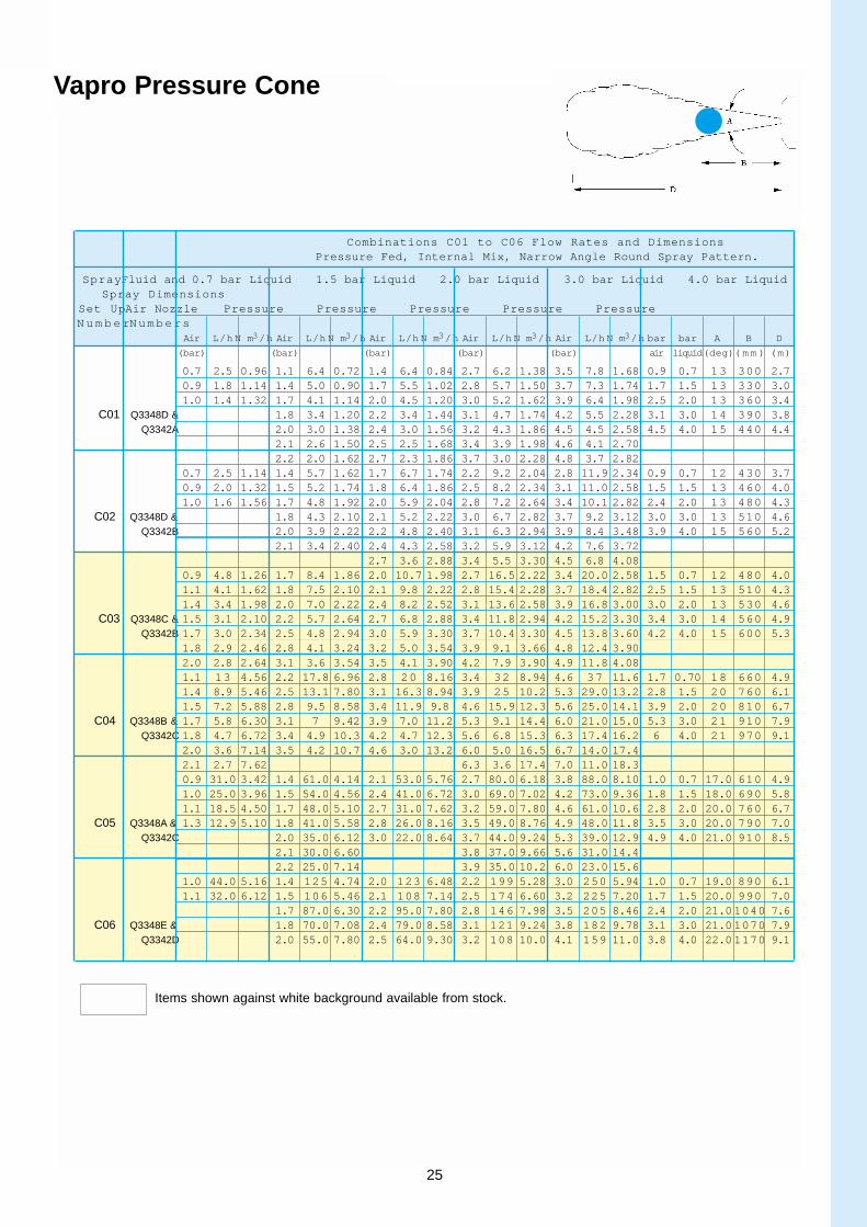
Combinations C01 to C06 Flow Rates and DimensionsPressure Fed, Internal Mix, Narrow Angle Round Spray Pattern.
SprayFluid and 0.7 bar Liquid 1.5 bar Liquid 2.0 bar Liquid 3.0 bar Liquid 4.0 bar LiquidSpray Dimensions
Set UpAir Nozzle Pressure Pressure Pressure Pressure PressureN u m b e rNumbers
Air L/h N m3/h Air L/h N m3/h Air L/h N m3/h Air L/h N m3/h Air L/h N m3/h bar bar A B D
(bar) (bar) (bar) (bar) (bar) air liquid(deg)( m m ) (m)
0.7 2.5 0.96 1.1 6.4 0.72 1.4 6.4 0.84 2.7 6.2 1.38 3.5 7.8 1.68 0.9 0.7 13 300 2.70.9 1.8 1.14 1.4 5.0 0.90 1.7 5.5 1.02 2.8 5.7 1.50 3.7 7.3 1.74 1.7 1.5 13 330 3.01.0 1.4 1.32 1.7 4.1 1.14 2.0 4.5 1.20 3.0 5.2 1.62 3.9 6.4 1.98 2.5 2.0 13 360 3.4
C01 Q3348D & 1.8 3.4 1.20 2.2 3.4 1.44 3.1 4.7 1.74 4.2 5.5 2.28 3.1 3.0 14 390 3.8Q3342A 2.0 3.0 1.38 2.4 3.0 1.56 3.2 4.3 1.86 4.5 4.5 2.58 4.5 4.0 15 440 4.4
2.1 2.6 1.50 2.5 2.5 1.68 3.4 3.9 1.98 4.6 4.1 2.702.2 2.0 1.62 2.7 2.3 1.86 3.7 3.0 2.28 4.8 3.7 2.82
0.7 2.5 1.14 1.4 5.7 1.62 1.7 6.7 1.74 2.2 9.2 2.04 2.8 11.9 2.34 0.9 0.7 12 430 3.70.9 2.0 1.32 1.5 5.2 1.74 1.8 6.4 1.86 2.5 8.2 2.34 3.1 11.0 2.58 1.5 1.5 13 460 4.01.0 1.6 1.56 1.7 4.8 1.92 2.0 5.9 2.04 2.8 7.2 2.64 3.4 10.1 2.82 2.4 2.0 13 480 4.3
C02 Q3348D & 1.8 4.3 2.10 2.1 5.2 2.22 3.0 6.7 2.82 3.7 9.2 3.12 3.0 3.0 13 510 4.6Q3342B 2.0 3.9 2.22 2.2 4.8 2.40 3.1 6.3 2.94 3.9 8.4 3.48 3.9 4.0 15 560 5.2
2.1 3.4 2.40 2.4 4.3 2.58 3.2 5.9 3.12 4.2 7.6 3.722.7 3.6 2.88 3.4 5.5 3.30 4.5 6.8 4.08
0.9 4.8 1.26 1.7 8.4 1.86 2.0 10.7 1.98 2.7 16.5 2.22 3.4 20.0 2.58 1.5 0.7 12 480 4.01.1 4.1 1.62 1.8 7.5 2.10 2.1 9.8 2.22 2.8 15.4 2.28 3.7 18.4 2.82 2.5 1.5 13 510 4.31.4 3.4 1.98 2.0 7.0 2.22 2.4 8.2 2.52 3.1 13.6 2.58 3.9 16.8 3.00 3.0 2.0 13 530 4.6
C03 Q3348C & 1.5 3.1 2.10 2.2 5.7 2.64 2.7 6.8 2.88 3.4 11.8 2.94 4.2 15.2 3.30 3.4 3.0 14 560 4.9Q3342B 1.7 3.0 2.34 2.5 4.8 2.94 3.0 5.9 3.30 3.7 10.4 3.30 4.5 13.8 3.60 4.2 4.0 15 600 5.3
1.8 2.9 2.46 2.8 4.1 3.24 3.2 5.0 3.54 3.9 9.1 3.66 4.8 12.4 3.902.0 2.8 2.64 3.1 3.6 3.54 3.5 4.1 3.90 4.2 7.9 3.90 4.9 11.8 4.081.1 13 4.56 2.2 17.8 6.96 2.8 20 8.16 3.4 32 8.94 4.6 37 11.6 1.7 0.70 18 660 4.91.4 8.9 5.46 2.5 13.1 7.80 3.1 16.3 8.94 3.9 25 10.2 5.3 29.0 13.2 2.8 1.5 20 760 6.11.5 7.2 5.88 2.8 9.5 8.58 3.4 11.9 9.8 4.6 15.9 12.3 5.6 25.0 14.1 3.9 2.0 20 810 6.7
C04 Q3348B & 1.7 5.8 6.30 3.1 7 9.42 3.9 7.0 11.2 5.3 9.1 14.4 6.0 21.0 15.0 5.3 3.0 21 910 7.9Q3342C 1.8 4.7 6.72 3.4 4.9 10.3 4.2 4.7 12.3 5.6 6.8 15.3 6.3 17.4 16.2 6 4.0 21 970 9.1
2.0 3.6 7.14 3.5 4.2 10.7 4.6 3.0 13.2 6.0 5.0 16.5 6.7 14.0 17.42.1 2.7 7.62 6.3 3.6 17.4 7.0 11.0 18.30.9 31.0 3.42 1.4 61.0 4.14 2.1 53.0 5.76 2.7 80.0 6.18 3.8 88.0 8.10 1.0 0.7 17.0 610 4.91.0 25.0 3.96 1.5 54.0 4.56 2.4 41.0 6.72 3.0 69.0 7.02 4.2 73.0 9.36 1.8 1.5 18.0 690 5.81.1 18.5 4.50 1.7 48.0 5.10 2.7 31.0 7.62 3.2 59.0 7.80 4.6 61.0 10.6 2.8 2.0 20.0 760 6.7
C05 Q3348A & 1.3 12.9 5.10 1.8 41.0 5.58 2.8 26.0 8.16 3.5 49.0 8.76 4.9 48.0 11.8 3.5 3.0 20.0 790 7.0Q3342C 2.0 35.0 6.12 3.0 22.0 8.64 3.7 44.0 9.24 5.3 39.0 12.9 4.9 4.0 21.0 910 8.5
2.1 30.0 6.60 3.8 37.0 9.66 5.6 31.0 14.42.2 25.0 7.14 3.9 35.0 10.2 6.0 23.0 15.6
1.0 44.0 5.16 1.4 125 4.74 2.0 123 6.48 2.2 199 5.28 3.0 250 5.94 1.0 0.7 19.0 890 6.11.1 32.0 6.12 1.5 106 5.46 2.1 108 7.14 2.5 174 6.60 3.2 225 7.20 1.7 1.5 20.0 990 7.0
1.7 87.0 6.30 2.2 95.0 7.80 2.8 146 7.98 3.5 205 8.46 2.4 2.0 21.01040 7.6C06 Q3348E & 1.8 70.0 7.08 2.4 79.0 8.58 3.1 121 9.24 3.8 182 9.78 3.1 3.0 21.01070 7.9
Q3342D 2.0 55.0 7.80 2.5 64.0 9.30 3.2 108 10.0 4.1 159 11.0 3.8 4.0 22.01170 9.1
Vapro Pressure Cone
Items shown against white background available from stock.
25

Combinations C20 to C27 Flow Rates and DimensionsPressure Fed, Internal Mix, Narrow Angle Round Spray Pattern.
SprayFluid and 0.7 bar Liquid 1.5 bar Liquid 2.0 bar Liquid 3.0 bar Liquid 4.0 bar LiquidSpray Dimensions
Set UpAir Nozzle Pressure Pressure Pressure Pressure PressureN u m b e rNumbers
Air L/h N m3/h Air L/h N m3/h Air L/h N m3/h Air L/h N m3/h Air L/h N m3/h bar bar C D
(bar) (bar) (bar) (bar) (bar) air liquid ( m m ) (m)
0.7 5.5 1.44 1.3 9.1 1.86 2.0 8.6 2.52 2.7 11.2 3.12 3.9 12.0 4.14 1.1 0.7 460 2.60.9 4.7 1.62 1.5 7.7 2.16 2.2 7.5 2.82 3.0 10.1 3.36 4.6 9.7 4.86 2.1 1.5 660 3.01.0 4.1 1.86 1.8 6.5 2.52 2.5 6.2 3.12 3.2 9.1 3.72 5.3 7.5 5.58 2.8 2.0 760 3.2
C20 Q3348D & 1.1 3.5 2.04 2.1 5.4 2.82 2.8 5.2 3.42 3.5 8.1 3.96 6.0 5.3 6.24 3.5 3.0 860 3.4Q3343A 1.3 3.0 2.22 2.4 4.3 3.12 3.1 4.2 3.78 4.2 5.4 4.74 6.3 4.3 6.60 6.0 4.0 940 4.0
1.4 2.5 2.40 2.7 3.3 3.42 3.2 3.7 3.90 4.6 4.2 5.10 6.7 3.3 6.961.5 2.0 2.64 2.8 2.8 3.60 3.4 3.2 4.08 4.9 3.1 5.46 7.0 2.4 7.321.3 3.9 1.80 2.1 7.4 2.40 3.0 6.1 3.12 3.9 9.4 3.60 5.3 10.2 4.68 1.5 0.7 460 1.81.4 3.0 1.98 2.4 5.3 2.70 3.1 5.3 3.24 4.2 7.2 4.02 5.6 8.3 5.04 2.7 1.5 690 2.01.5 2.3 2.10 2.5 4.4 2.82 3.2 4.5 3.42 4.6 5.3 4.38 6.0 6.6 5.34 3.2 2.0 910 2.0
C21 Q3348C & 1.7 1.8 2.28 2.7 3.7 3.00 3.4 3.8 3.54 4.9 3.8 4.80 6.3 5.1 5.88 4.2 3.0 940 2.1Q3343C 1.8 1.3 2.46 2.8 3.1 3.12 3.5 3.2 3.70 5.6 4.0 970 2.3
2.0 1.0 2.64 3.0 2.6 3.30 3.9 1.8 4.083.1 2.1 3.42
0.9 8.2 1.20 1.4 14.4 1.62 2.1 13.5 2.16 2.7 19.1 2.52 4.6 16.1 4.14 1.1 0.7 710 2.11.0 6.8 1.38 1.7 11.9 1.92 2.4 11.4 2.52 3.0 17.1 2.76 4.9 13.8 4.56 2.1 1.5 810 2.41.1 5.5 1.62 2.0 9.5 2.22 2.7 9.2 2.82 3.2 15.1 3.12 5.3 11.5 4.96 3.0 2.0 890 2.6
C22 Q3348C & 1.3 4.1 1.80 2.1 8.3 2.40 3.0 7.1 3.18 3.5 13.1 3.42 5.6 9.3 5.40 3.5 3.0 970 2.7Q3343A 1.4 2.9 2.40 2.2 7.1 2.58 3.2 5.0 3.54 4.2 8.1 4.32 6.0 7.3 5.82 5.6 4.0 970 3.2
2.4 6.1 2.76 3.4 4.0 3.78 4.6 5.9 4.74 6.3 5.6 6.242.5 5.1 2.94 3.5 3.3 3.96 4.9 4.0 5.16 6.7 4.3 6.72
1.0 9.0 1.50 2.0 10.4 2.46 2.4 11.6 2.88 3.1 15.6 3.36 4.2 17.1 4.30 1.4 0.70 170 3.01.1 7.8 1.80 2.1 9.3 2.70 2.5 10.4 3.06 3.2 14.6 3.54 4.6 15.0 4.80 2.5 1.5 200 3.71.3 6.6 1.92 2.2 8.2 2.88 2.7 9.4 3.24 3.4 13.7 3.72 4.9 12.8 5.22 3.2 2.0 220 4.0
C23 Q3348C & 1.4 5.2 2.16 2.5 6.1 3.30 3.0 7.3 3.66 3.8 10.8 4.26 5.3 11.0 5.64 3.8 3.0 280 4.2Q3343B 1.7 3.1 2.64 2.9 4.3 3.72 3.2 5.5 4.08 4.2 8.5 4.92 5.6 9.4 6.18 5.3 4.0 330 4.8
2.0 2.0 3.00 3.1 3.0 4.14 3.5 4.1 4.50 4.9 5.2 5.88 6.3 7.2 7.142.2 1.1 3.36 3.4 2.0 4.50 3.8 2.9 4.86 6.0 2.3 7.20 7.0 6.1 8.041.1 11.2 3.24 2.1 18.0 4.74 2.7 19.6 5.58 3.5 27.0 6.72 4.6 33.0 8.22 1.1 0.70 200 3.01.3 8.5 3.60 2.2 15.8 5.04 2.8 17.3 5.88 3.7 25.0 6.96 4.9 28.0 8.94 2.4 1.5 330 3.2
C24 Q3348B & 1.4 6.5 3.90 2.4 13.6 5.34 3.0 15.2 6.18 3.8 23.0 7.26 5.3 24.0 9.66 3 2.0 460 3.4Q3343D 1.5 5.0 4.26 2.5 11.6 5.70 3.1 13.2 6.54 3.9 21.0 7.56 5.6 19.7 10.4 3.7 3.0 460 3.5
1.7 3.8 4.62 3.2 11.4 6.84 4.1 18.9 7.92 6.0 15.7 11.2 5.3 4.0 480 4.04.2 17.0 8.22 6.3 12.4 12.0
0.9 27.0 1.98 1.8 38.0 3.30 2.4 39 4.02 3.2 58.0 4.56 4.6 59.0 6.36 1.4 0.70 300 3.41.0 20.0 2.28 2.1 28.0 3.96 2.7 30 4.62 3.5 47.0 5.22 5.3 40.0 7.92 2.4 1.5 410 3.51.1 15.9 2.70 2.2 24.0 4.26 3.0 24 5.22 3.8 38.0 5.82 5.6 32.0 8.70 3.2 2.0 430 3.7
C25 Q3348A & 1.3 12.5 2.88 2.4 21.0 4.56 3.2 17.8 5.88 3.9 34.0 6.18 6.0 26.0 9.48 3.9 3.0 480 3.8Q3343D 1.4 10.2 3.36 2.5 17.8 4.92 3.4 15.1 6.18 4.2 27.0 6.78 6.3 20.0 10.3 6 4.0 510 4.4
1.5 7.6 3.72 2.7 15.1 5.22 3.5 12.9 6.54 4.6 20.0 7.56 6.7 15.9 11.13.7 10.6 6.84 4.9 14.8 8.40 7.0 12.7 11.9
1.0 17.0 1.38 2.0 24.0 2.64 2.4 28 3.06 3.4 38.0 4.32 3.9 65.0 4.50 1.1 0.70 150 2.41.1 11.0 1.62 2.1 18.9 3.00 2.5 23 3.54 3.5 33.0 4.80 4.2 53.0 5.34 2.1 1.5 170 3.01.3 7.6 1.98 2.2 14.4 3.36 2.7 18.9 3.96 3.7 28.0 5.34 4.6 40.0 6.48 2.8 2.0 220 3.4
C26 Q3348A & 1.4 3.2 2.40 2.4 10.6 3.78 2.8 15.1 4.44 3.8 23.0 5.82 4.9 30.0 7.62 3.7 3.0 280 3.6Q3343E 2.5 7.2 4.26 3.0 11.7 4.74 3.9 19.7 6.30 5.3 21.0 8.94 4.9 4.0 350 4.0
4.2 13.1 7.20 5.6 13.8 10.44.6 7.2 8.28 6.3 3.2 13.5
1.0 29.0 5.40 1.8 56.0 7.02 2.1 100 7.14 3.0 125 8.40 4.1 140 10.9 1 0.70 250 3.41.1 18.9 6.48 2.0 40.0 7.98 2.2 79 7.96 3.1 110 9.06 4.2 125 11.6 1.8 1.5 430 3.8
2.4 62 8.82 3.2 95.0 9.78 4.6 89.0 13.5 2.4 2.0 460 4.3C27 Q3348E & 2.5 48 9.72 3.4 78.0 11.0 4.9 58.0 15.9 3.4 3.0 530 4.6
Q3343F 2.7 36 10.60 3.5 62.0 11.6 5.3 34.0 18.3 4.9 4.0 580 5.23.7 48.0 12.6 5.6 16.7 20.4
Vapro Pressure Fan
26

Combinations C50 to C55 Flow Rates and DimensionsPressure Fed, Internal Mix, Narrow Angle Round Spray Pattern.
SprayFluid and 0.2 bar Liquid 0.3 bar Liquid 0.7 bar Liquid 1.5 bar Liquid 3.0 bar LiquidSpray Dimensions
Set UpAir Nozzle Pressure Pressure Pressure Pressure PressureN u m b e rNumbers
Air L/h N m3/h Air L/h N m3/h Air L/h N m3/h Air L/h N m3/h Air L/h N m3/h bar bar C D B
(bar) (bar) (bar) (bar) (bar) air liquid( m m ) ( m m )
( m m )
0.4 0.3 330 1200 2800.35 1.32 0.4 1.32 0.4 1.50 0.6 1.68 0.7 2.04 0.6 0.7 400 1800 3000.4 1.50 0.4 1.50 0.6 1.68 0.7 2.04 1.1 2.70 0.6 1.5 460 1800 350
C50 Q3348G & 2.8 3.5 5.3 7.8 11 1.1 1.5 430 2400 330Q3345A 0.5 1.62 0.6 1.68 0.7 2.04 1.1 2.70 1.8 3.72 1.4 1.5 41 2700 300
0.6 1.68 0.7 2.04 0.9 2.40 1.4 3.24 2.5 4.74 1.1 2.0 480 2600 3501.4 3.0 510 2700 380
0.2 1.51 0.4 1.58 0.7 1.87 1.4 2.72 2.8 4.38 0.2 0.2 230 900 1500.4 1.58 0.7 1.87 1.1 2.38 1.8 3.23 3.5 5.10 1.05 0.2 230 1200 1500.7 1.87 1.1 2.38 1.4 2.72 2.1 3.57 4.2 6.12 1.4 0.35 230 1200 150
C51 Q3348G & 1.1 2.8 2.38 1.4 3.5 2.72 1.8 5.3 3.23 2.8 7.8 4.42 4.9 11 7.14 1.4 1.4 250 1500 180Q3345C 1.4 2.72 1.8 3.23 2.1 3.56 3.5 5.10 5.3 7.65 1.75 0.7 240 1500 150
1.8 3.23 2.1 3.56 2.8 4.42 4.2 6.12 5.6 8.34 2.8 1.4 280 1800 1802.1 3.56 2.8 4.42 3.5 5.10 5.6 8.34 6.3 9.54 4.9 2.8 240 2400 180
0.35 0.2 220 1000 1400.4 1.32 0.4 1.32 0.6 1.68 0.7 2.04 1.1 2.70 1.4 0.2 220 1700 1500.6 1.68 0.7 2.40 0.7 2.04 1.4 3.24 1.4 3.24 1.75 0.35 230 1800 165
C52 Q3348D & 4.5 5.5 8.3 12.2 17 1.75 1.4 290 2100 190Q3345A 0.7 2.04 1.1 2.70 1.4 3.24 2.1 4.26 2.1 4.26 2.1 0.7 250 1800 180
1.1 2.70 1.4 3.24 2.1 4.26 2.5 4.74 2.5 4.74 3.5 1.4 300 2400 2205.3 2.8 250 3000 190
0.4 1.58 0.7 1.87 1.1 2.38 1.8 3.23 3.2 4.92 0.7 0.3 400 1500 3300.7 1.87 1.1 2.38 1.4 2.72 2.1 3.56 3.5 5.10 1.1 0.7 480 2100 3801.1 2.38 1.4 2.72 1.8 3.23 2.8 4.42 4.2 6.12 0.7 1.5 580 1800 460
C53 Q3348D & 1.4 4.5 2.72 1.8 5.5 3.23 2.1 8.3 3.56 3.5 12.2 5.10 4.9 17 7.14 1.4 1.5 560 2400 430Q3345C 1.8 3.23 2.1 3.56 2.8 4.42 4.2 6.12 5.3 7.62 2.5 1.5 510 3000 400
2.1 3.56 2.8 4.42 3.5 5.10 4.9 7.14 6.3 9.54 1.8 2.0 580 2700 4602.8 4.42 3.5 5.10 4.2 6.12 6.3 9.54 6.7 9.84 1.8 3.0 660 2900 480
0.7 0.2 250 1200 1650.4 1.50 0.4 1.50 0.4 1.50 0.7 2.04 1.4 3.24 1.75 0.2 250 1800 1650.5 1.65 0.6 1.68 0.6 1.60 0.9 2.40 1.8 3.72 2.1 0.35 240 1800 180
C54 Q3348C & 8.5 10.4 15.9 23 33 2.5 1.4 320 1800 200Q3345A 0.6 1.68 0.7 1.86 0.7 2.04 1.1 2.70 2.1 4.26 2.8 0.7 300 2300 190
0.7 2.04 0.7 2.04 0.9 2.40 1.4 3.24 2.5 4.74 4.2 1.4 360 3000 2005.3 2.8 300 4000 200
0.7 1.87 1.1 2.38 1.4 2.72 2.5 4.08 3.5 5.10 0.6 0.3 610 1800 4801.1 2.38 1.4 2.72 1.8 3.23 2.8 4.42 4.2 6.12 0.6 0.7 630 1500 4801.4 2.72 1.8 3.23 2.1 3.56 3.5 5.10 4.9 7.14 0.7 1.5 630 1800 480
C55 Q3348C & 1.8 8.5 3.23 2.1 10.4 3.56 2.8 15.9 4.42 4.2 23 6.12 5.3 33 7.62 1.1 1.5 660 2100 510Q3345C 2.1 3.56 2.8 4.42 3.5 5.10 4.9 7.14 5.6 8.34 1.4 1.5 660 2400 530
Vapro External Fan
Items shown against white background available from stock.
27

Combinations C56 to C64 Flow Rates and DimensionsPressure Fed, Internal Mix, Narrow Angle Round Spray Pattern.
SprayFluid and 0.3 bar Liquid 0.3 bar Liquid 0.7 bar Liquid 1.5 bar Liquid 3.0 bar LiquidSpray Dimensions
Set UpAir Nozzle Pressure Pressure Pressure Pressure PressureN u m b e rNumbers
Air L/h N m3/h Air L/h N m3/h Air L/h N m3/h Air L/h N m3/h Air L/h N m3/h bar bar C D B
(bar) (bar) (bar) (bar) (bar) air liquid( m m )( m m )
( m m )
0.7 0.2 250 1700 1900.6 5.46 0.7 6.12 1.4 9.36 2.1 12.6 3.2 17.1 1.8 0.2 250 2700 1900.7 6.12 1.1 7.80 2.1 9.12 2.8 15.6 4.2 21.6 2.1 0.35 280 3000 190
C56 Q3348F & 13.4 16.4 25 37 52 2.5 0.7 280 3500 220Q3345B 1.1 7.80 1.8 11.0 2.5 14.1 3.5 18.6 5.3 25.8 2.5 1.4 360 3700 230
1.4 9.36 2.1 12.6 2.8 15.6 4.2 21.6 5.6 27.3 4.2 1.4 370 4300 2304.9 2.8 320 4900 220
0.7 5.10 1.0 6.12 1.4 6.96 2.5 10.7 3.2 12.7 1.4 0.3 480 3800 3801.0 6.12 1.4 6.96 1.8 8.34 2.8 11.7 3.5 13.9 2.1 0.7 560 4300 4001.4 6.96 1.8 8.34 2.1 9.36 3.5 13.6 3.9 15.3 2.1 1.5 580 4000 460
C57 Q3348F & 1.8 13.4 8.34 2.1 16.4 9.36 2.5 25 10.7 4.2 37 16.0 4.2 52 16.5 3.2 1.5 660 4600 480Q3345D 2.1 9.36 2.8 11.7 2.8 11.7 4.9 18.7 4.9 18.8 4.2 1.5 640 5200 480
2.8 11.7 3.5 13.6 3.5 13.6 5.6 21.6 5.6 21.6 3.9 2.0 690 4600 5103.5 13.6 4.2 16.0 4.2 16.0 6.3 24.7 6.3 24.7 4.2 3.0 710 4900 510
0.7 0.35 270 2100 1900.6 5.46 0.7 6.12 1.1 7.80 2.5 14.1 3.5 18.6 1.8 0.7 270 3000 1901.1 7.80 1.4 9.36 1.8 11.0 3.2 17.1 4.6 22.8 2.5 1.4 330 3400 220
C58 Q3348B & 17.6 22 33 48 68 2.8 1.4 360 3800 220Q3345B 1.4 9.36 1.8 11.0 2.5 14.1 3.9 19.8 6.0 28.5 2.8 1.4 370 4000 250
1.8 11.0 2.1 12.6 2.8 15.6 4.2 21.6 6.7 31.5 4.2 2.1 370 4900 2505.3 2.8 360 5800 230
0.7 5.10 1.4 6.96 1.8 8.34 2.8 11.7 3.5 13.9 1.1 0.2 510 3500 3801.0 6.12 1.8 8.34 2.1 9.36 3.2 12.7 4.2 16.5 1.8 0.7 640 3000 4801.4 6.96 2.1 9.36 2.5 10.7 3.5 13.6 4.9 18.8 2.5 1.5 640 3800 460
C59 Q3348B & 1.8 18 8.34 2.5 22 10.7 2.8 33 11.7 4.2 48 16.0 5.3 68 20.4 3.2 1.5 610 4300 430Q3345D 2.1 9.36 2.8 11.7 3.5 13.6 4.9 18.7 5.6 21.6 4.2 1.5 580 4900 430
2.8 11.7 3.5 13.6 4.2 16.0 5.6 21.6 6.3 24.7 4.2 2.0 610 5200 4303.5 13.6 4.2 16.0 4.9 18.7 6.3 24.7 6.6 25.7 4.9 3.0 610 4000 430
1.0 0.2 150 2700 2000.7 6.12 1.1 7.80 1.8 11.0 3.2 17.1 2.1 0.2 150 3000 2201.1 7.80 1.4 9.36 2.1 12.6 3.5 18.6 2.8 0.35 180 3500 240
C60 Q3348A & 36 45 68 100 3.2 1.4 200 3700 280Q3345B 1.4 9.36 2.1 12.6 2.8 15.6 4.9 24.3 3.5 0.7 190 4000 270
1.8 11.0 2.5 14.1 3.2 17.1 5.9 27.3 4.2 1.4 200 4800 2805.6 2.8 180 5900 240
1.0 6.12 1.8 8.34 2.5 10.7 3.2 12.7 3.9 15.3 1.8 0.2 150 3000 2001.4 6.96 2.1 9.36 2.8 11.7 3.5 13.6 4.2 16.5 2.8 0.2 150 3400 2001.8 8.34 2.5 10.7 3.2 12.7 3.9 14.8 4.6 17.8 2.8 0.3 150 4000 200
C61 Q3348A & 2.1 36 9.36 2.8 45 11.7 3.5 68 13.6 4.2 100 16.0 4.9 141 18.8 3.5 0.7 170 4300 220Q3345D 2.5 10.7 3.2 12.7 4.2 16.0 4.9 18.7 5.6 21.6 3.9 1.5 170 4600 220
2.8 11.7 3.5 13.6 4.9 18.7 5.6 21.6 6.3 24.7 4.2 1.0 170 4700 2303.5 13.6 4.2 16.0 5.6 21.6 6.3 24.7 7.0 27.2 4.9 0.5 170 5500 2301.8 14.1 1.8 14.1 2.5 18.0 3.9 24.6 2.1 0.3 760 3000 5602.1 15.6 2.1 15.6 2.8 19.8 4.2 26.7 2.8 0.7 810 4000 5802.5 18.0 2.5 18.0 3.2 21.3 4.6 28.8 3.2 1.5 790 4300 580
C62 Q3348H & 2.8 36 19.8 2.8 45 19.8 3.5 68 22.8 4.9 100 31.2 4.6 1.5 760 4900 530Q3345E 3.2 21.3 3.2 21.3 3.9 24.6 5.3 33.9 5.6 1.5 660 5800 510
3.5 22.8 3.5 22.8 4.2 26.7 5.6 36.0 3.9 2.0 840 4300 6404.2 26.7 4.2 26.7 4.9 31.2 6.3 41.1 6.3 3.0 790 5800 5602.1 15.6 2.8 19.8 3.9 24.6 4.9 31.2 2.1 0.2 170 3500 2402.5 18.0 3.2 21.3 4.2 26.7 5.3 33.9 3.2 0.2 180 4300 2402.8 19.8 3.5 22.8 4.6 28.8 5.6 36.0 3.9 0.3 180 4900 250
C63 Q3348I & 3.2 64 21.3 3.9 78 24.6 4.9 119 31.2 6.0 175 38.4 4.9 0.7 180 5500 250Q3345E 3.5 22.8 4.2 26.7 5.3 33.9 6.3 41.1 4.9 1.5 200 5500 250
4.2 26.7 4.9 31.2 5.6 36.0 5.3 1.0 180 5800 2504.9 31.2 5.6 36.0 6.3 41.1 5.6 1.5 200 6100 2502.8 19.8 3.5 22.8 4.6 28.8 5.6 36.0 2.8 0.2 190 4600 2503.2 21.3 3.9 24.6 4.9 31.2 6.0 38.4 3.9 0.2 200 4900 2503.5 22.8 4.2 26.7 5.3 33.9 6.3 41.1 4.6 0.3 200 5200 250
C64 Q3348E & 3.9 102 24.6 4.6 125 28.8 5.6 192 36.0 280 5.3 0.7 220 5500 270Q3345E 4.2 26.7 4.9 31.2 6.0 38.4 5.6 1.0 220 5500 270
Vapro External Fan
28

Combinations C10 to C15 Flow Rates and DimensionsPressure Fed, Internal Mix, Narrow Angle Round Spray Pattern.
SprayFluid and 0.7 bar Liquid 1.5 bar Liquid 2.0 bar Liquid 3.0 bar Liquid 4.0 bar LiquidSpray Dimensions
Set UpAir Nozzle Pressure Pressure Pressure Pressure PressureN u m b e rNumbers
Air L/h N m3/h Air L/h N m3/h Air L/h N m3/h Air L/h N m3/h Air L/h N m3/h bar bar C D
(bar) (bar) (bar) (bar) (bar) air liquid ( m m ) (m)
0.6 5.3 0.60 1.1 8.1 0.78 1.5 8.1 0.96 2.4 8.9 1.32 3.1 10.5 1.44 0.7 0.7 230 1.50.7 4.3 0.72 1.3 7.0 0.96 1.8 6.6 1.26 2.7 8.1 1.56 3.4 9.7 1.68 1.4 1.5 240 1.8
C10 Q3348D & 0.9 3.0 0.84 1.4 6.4 1.02 2.1 4.9 1.50 3.0 6.4 1.80 3.9 7.8 2.16 1.8 2.0 250 2.1Q3344A 1.0 1.7 1.02 1.5 5.5 1.14 2.4 3.2 1.74 3.2 4.9 2.04 4.2 6.1 2.52 3.0 3.0 260 2.7
1.7 4.5 1.32 3.4 4.2 2.22 4.6 4.4 2.82 3.9 4.0 300 4.01.8 3.5 1.44 3.5 3.4 2.40 4.9 2.8 3.24
0.9 7.0 3.00 1.7 13.2 4.08 2.0 18.5 4.08 2.8 25.0 5.04 3.7 31.0 5.76 0.9 0.7 310 1.81.0 2.1 3.72 1.8 9.8 4.74 2.1 15.1 4.56 3.0 22.0 5.52 3.8 28.0 6.30 1.7 1.5 330 2.4
2.2 11.7 5.10 3.1 18.5 6.06 3.9 26.0 6.78 2.1 2.0 330 3.2C11 Q3348B & 3.2 15.1 6.54 4.1 23.0 7.32 3.2 3.0 340 4.1
Q3344C 3.4 12.1 7.14 4.2 20.0 7.80 4.1 4.0 370 5.93.5 9.1 7.80 4.6 13.6 9.183.7 6.1 8.52 4.9 6.8 11.00
1.1 12.3 2.40 2.2 16.3 3.72 2.7 21.0 4.14 4.2 19.3 6.00 5.6 22.0 7.80 1.5 0.7 230 2.71.3 9.9 2.70 2.5 12.1 4.26 3.0 16.3 4.68 4.6 14.6 6.78 6.0 17.6 8.52 3.0 1.5 240 4.61.4 7.9 3.00 2.8 8.9 4.74 3.2 12.3 5.16 4.9 10.8 7.44 6.3 14.0 9.12 3.4 2.0 240 5.5
C12 Q3348B & 1.5 6.1 3.24 3.0 7.6 4.98 3.4 10.7 5.46 5.3 8.1 8.10 6.7 11.4 9.78 5.3 3.0 250 7.3Q3344B 1.7 4.9 3.48 3.1 6.4 5.22 3.5 9.3 5.64 5.6 6.2 8.76 7.0 9.1 10.4 6.3 4.0 300 9.4
1.8 3.9 3.72 3.2 5.5 5.46 3.9 6.4 6.30 6.0 4.9 9.422.0 3.1 4.02 3.4 4.7 5.70 4.2 4.7 6.90 6.3 4.0 10.00.7 24.0 1.92 1.4 43.0 2.22 2.1 33.0 3.96 2.8 52.0 3.90 3.7 63.0 4.08 0.9 0.7 360 2.10.9 13.6 2.64 1.5 35.0 2.94 2.2 26.0 4.68 3.0 46.0 4.56 3.8 58.0 4.74 1.5 1.5 370 3.21.0 7.6 3.42 1.7 28.0 3.66 2.4 18.9 5.34 3.1 39.0 5.22 4.0 52.0 6.06 2.4 2.0 370 4.1
C13 Q3348A & 1.8 21.0 4.26 2.5 11.7 6.00 3.2 33.0 5.94 4.2 41.0 6.66 3.2 3.0 380 5.0Q3344C 3.4 26.0 6.60 4.6 27.0 8.28 3.9 4.0 390 6.8
3.5 19.5 7.32 4.9 15.9 9.963.7 13.2 7.98
1.3 36.0 5.10 2.1 57.0 6.96 3.1 53.0 9.36 4.2 64.0 11.8 5.6 74.0 14.7 2.0 0.7 330 5.51.5 29.0 6.12 2.4 51.0 7.80 3.2 50.0 9.78 4.9 51.0 13.8 6.0 68.0 15.6 3.0 1.5 340 6.41.8 23.0 7.02 2.7 45.0 8.58 3.4 47.0 10.2 5.6 40.0 15.9 6.3 62.0 16.8 3.9 2.0 370 8.2
C14 Q3348A & 2.0 19.7 7.50 3.0 39.0 9.42 3.5 45.0 10.6 6.0 34.0 17.1 6.7 56.0 17.7 6.0 3.0 380 9.1Q3344D 2.1 16.7 7.98 3.2 33.0 10.20 3.9 38.0 11.6 6.3 28.0 18.0 7.0 51.0 18.9 6.3 4.0 400 10.4
2.3 14.0 8.52 3.5 28.0 11.10 4.6 25.0 13.8 6.7 22.0 19.22.4 11 8.94 4.2 13.6 13.20 4.9 19 14.7 7.0 17.8 20.11.7 25 9.36 3.0 39.0 13.8 3.4 50.0 15.0 4.6 62.0 19.2 6.0 93.0 23.7 2.0 0.7 460 5.51.8 20 10.0 3.1 33.0 14.4 3.5 43.0 15.6 4.9 47.0 20.7 6.3 77.0 25.5 3.2 1.5 470 6.42.0 15 10.7 3.2 27.0 15.3 3.7 41.0 16.5 5.3 36.0 22.5 6.7 62.0 27.6 3.9 2.0 510 7.3
C15 Q3348E & 2.1 11 11.6 3.4 23.0 15.9 3.9 27.0 18.0 5.6 26.0 24.3 7.0 52.0 29.7 5.3 3.0 530 7.9Q3344E 2.3 7.6 12.3 3.5 18.5 16.8 4.1 23.0 18.6 6.0 18.9 26.1 6.3 4.0 580 9.8
Vapro Pressure Wide Cone
29
C

COMBINATION C30 TO C35 Flow Rates and DimensionsSiphon Fed, Internal Mix, Round Spray Pattern.
Liquid Capacity in L/hSpray Dimensions at
Atomising Air Gravity Head Siphon Head 200mm heightSpray Fluid & Air Air Air SpraySet Up Air Nozzle (bar) Capacity 450mm 300mm 150mm 100mm 200mm 300mm 600mm 900mm (bar) Angle B (mm) D (m)
Number Numbers Nm3/h A (deg)
0.7 0.66 1.5 1.3 1.1 0.9 0.7 0.5 0.7 18 280 1.8C30 Q3348G & 1.5 1.02 1.8 1.7 1.5 1.3 1.2 1.1 0.6 1.5 18 280 1.9
Q3341A 3.0 1.68 2.1 1.9 1.7 1.5 1.4 1.3 1.1 0.8 3.0 18 300 2.34.0 2.16 2.2 2.0 1.8 1.6 1.5 1.4 1.2 0.9 4.0 18 360 2.60.7 0.78 2.4 2.1 1.7 1.5 1.2 0.8 0.7 18 300 2.1
C31 Q3348D & 1.5 1.20 2.8 2.6 2.4 2.1 1.9 1.6 0.9 1.5 18 330 2.3Q3341A 3.0 1.92 3.4 3.1 2.9 2.8 2.6 2.4 1.7 1.1 3.0 18 380 2.6
4.0 2.46 3.7 3.4 3.3 3.1 2.9 2.7 2.1 1.5 4.0 19 430 3.00.7 1.38 2.5 2.3 2.0 1.6 1.4 1.1 0.7 18 300 2.4
C32 Q3348D & 1.5 2.16 2.9 2.8 2.5 2.2 2.0 1.7 0.9 1.5 18 330 2.7Q3341B 3.0 3.48 3.4 3.3 3.2 2.9 2.8 2.5 1.9 1.2 3.0 19 380 3.4
4.0 4.44 3.7 3.6 3.5 3.4 3.3 3.0 2.5 2.0 4.0 20 430 4.00.7 1.14 4.5 4 3.4 2.1 1.6 1.4 0.7 21 380 3.0
C33 Q3348C & 1.5 1.86 5.3 4.9 4.4 3.5 2.9 2.7 1.8 1.5 21 410 3.4Q3341B 3.0 3.00 6.0 5.6 5.0 4.4 4.0 3.4 2.4 1.2 3.0 21 460 4.0
4.0 3.90 5.7 5.4 5.0 4.2 3.9 3.5 2.8 1.9 4.0 22 510 4.61.5 3.48 22 19.9 16.3 12.3 10.5 8.3 2.8 1.5 17 460 3.7
C34 Q3348A & 3.0 5.28 25 23 19.5 16.7 14.2 11.5 6.4 2.8 3.0 18 510 4.3Q3341D 4.0 6.66 26 24 21 18.4 15.7 12.9 7.9 4.5 4.0 18 530 4.9
5.6 8.82 26 24 22 19.7 17 14.6 9.8 6.1 5.6 19 580 5.52.0 8.64 27 22 16.8 2.0 20 510 6.7
C35 Q3348E & 3.0 11.4 30 26 21 3.0 20 530 7.0Q3341E 4.0 14.4 43 40 31 28 23 11.0 4.0 21 580 7.6
COMBINATION C40 TO C43 Flow Rates and DimensionsSiphon Fed, Internal Mix, Flat Fan Spray Pattern.
Liquid Capacity in L/hSpray Dimensions at
Atomising Air Gravity Head Siphon Head 200mm heightSpray Fluid & AirSet Up Air Nozzle Air Capacity 450mm 300mm 150mm 100mm 200mm 300mm 600mm 900mm Air C D
Number Numbers (bar) Nm 3/h (bar) (mm) (mm)
0.7 1.68 1.3 1.2 1.1 1.0 1.0 0.8 0.6 0.5 0.7 380 2.1C40 Q3348C & 1.5 2.58 1.2 1.1 1.0 0.9 0.9 0.8 0.7 0.5 1.5 380 2.1
Q3340A 2.0 3.00 0.8 0.8 0.7 0.6 0.5 2.0 380 1.8
1.5 3.36 3.7 3.5 3.3 2.9 2.8 2.5 2.3 2.1 1.5 380 2..7 C41 Q3348F & 2.0 3.90 3.4 3.3 3.1 2.8 2.7 2.6 2.4 2.2 2.0 420 2.7
Q3340B 3.0 5.22 2.8 2.7 2.5 2.4 2.2 2.1 1.9 1.7 3.0 460 3.04.0 6.60 1.9 1.8 1.6 1.5 1.3 1.2 4.0 480 2.71.5 4.08 5.1 4.8 4.5 3.8 3.7 3.5 3.0 2.4 1.5 270 3.4
C42 Q3348B & 2.0 4.68 4.9 4.7 4.4 3.6 3.4 3.2 2.9 2.3 2.0 280 3.4Q3340C 3.0 6.18 3.4 3.2 3.0 2.2 2.0 1.7 3.0 300 3.0
3.5 7.02 2.2 2.0 1.71.5 3.78 7.6 7.2 6.6 5.7 5.4 5.1 4.6 3.7 1.5 270 3.4
C43 Q3348B & 2.0 4.38 7.6 7.3 6.8 5.9 5.7 5.5 5.0 4.2 2.0 290 3.4Q3340D 3.0 5.76 6.4 6.1 5.7 5.0 4.5 4.1 3.3 3.0 330 3.4
3.5 6.60 4.2 3.7 3.2 2.6
Vapro Siphon Cone
Vapro Siphon Fan
30
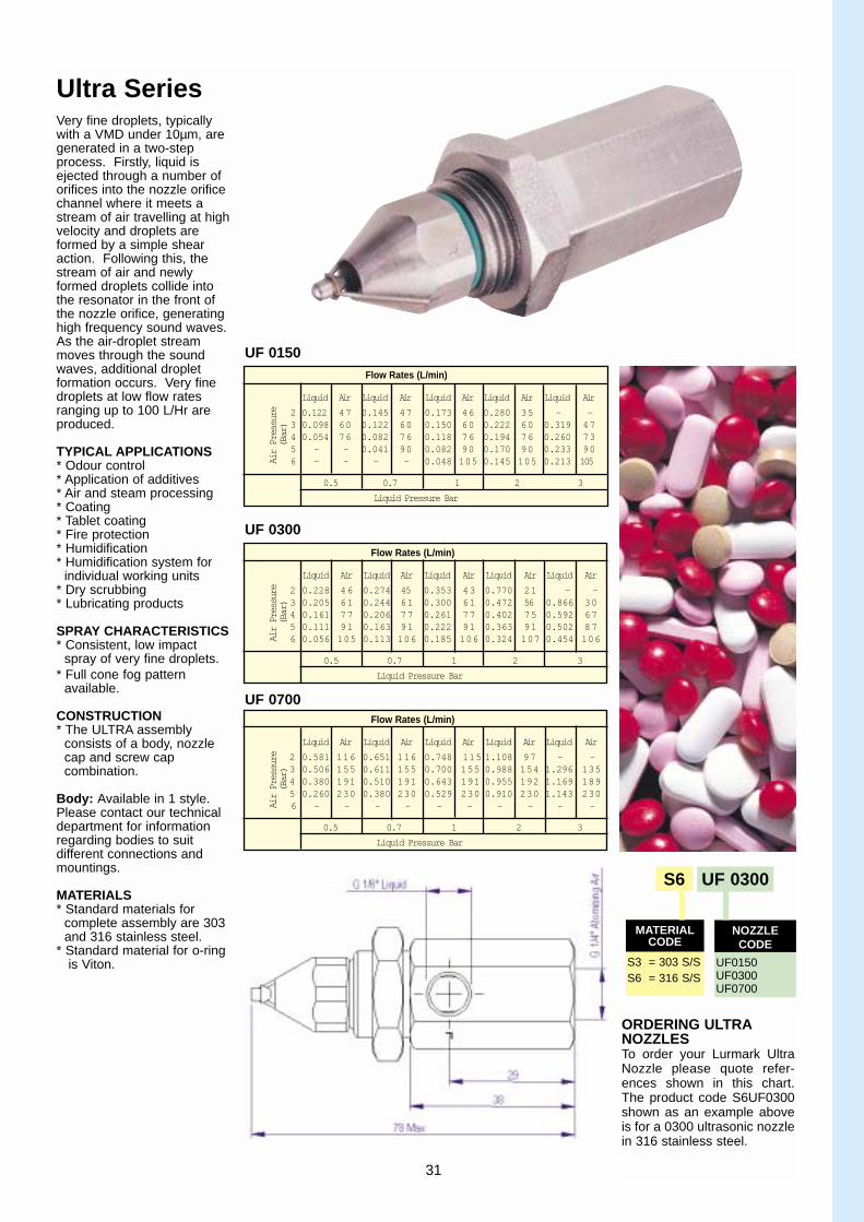
Ultra SeriesVery fine droplets, typicallywith a VMD under 10µm, aregenerated in a two-stepprocess. Firstly, liquid isejected through a number oforifices into the nozzle orificechannel where it meets astream of air travelling at highvelocity and droplets areformed by a simple shearaction. Following this, thestream of air and newlyformed droplets collide intothe resonator in the front ofthe nozzle orifice, generatinghigh frequency sound waves.As the air-droplet streammoves through the soundwaves, additional droplet formation occurs. Very finedroplets at low flow ratesranging up to 100 L/Hr areproduced.
TYPICAL APPLICATIONS* Odour control* Application of additives* Air and steam processing* Coating* Tablet coating* Fire protection* Humidification* Humidification system for
individual working units* Dry scrubbing* Lubricating products
SPRAY CHARACTERISTICS* Consistent, low impact
spray of very fine droplets.* Full cone fog pattern
available.
CONSTRUCTION* The ULTRA assembly
consists of a body, nozzle cap and screw cap combination.
Body: Available in 1 style.Please contact our technicaldepartment for informationregarding bodies to suit different connections andmountings.
MATERIALS* Standard materials for
complete assembly are 303 and 316 stainless steel.
* Standard material for o-ringis Viton.
Flow Rates (L/min)
Liquid Air Liquid Air Liquid Air Liquid Air Liquid Air
2 0.228 46 0.274 45 0.353 43 0.770 21 - -3 0.205 61 0.244 61 0.300 61 0.472 56 0.866 304 0.161 77 0.206 77 0.261 77 0.402 75 0.592 675 0.111 91 0.163 91 0.222 91 0.363 91 0.502 876 0.056 105 0.113 106 0.185 106 0.324 107 0.454 106
0.5 0.7 1 2 3
Liquid Pressure Bar
Air Pressure
(Bar)
Flow Rates (L/min)
Liquid Air Liquid Air Liquid Air Liquid Air Liquid Air
2 0.581 116 0.651 116 0.748 115 1.108 97 - -3 0.506 155 0.611 155 0.700 155 0.988 154 1.296 1354 0.380 191 0.510 191 0.643 191 0.955 192 1.169 1895 0.260 230 0.380 230 0.529 230 0.910 230 1.143 2306 - - - - - - - - - -
0.5 0.7 1 2 3
Liquid Pressure Bar
Air Pressure
(Bar)
Flow Rates (L/min)
Liquid Air Liquid Air Liquid Air Liquid Air Liquid Air
2 0.122 47 0.145 47 0.173 46 0.280 35 - - 3 0.098 60 0.122 60 0.150 60 0.222 60 0.319 474 0.054 76 0.082 76 0.118 76 0.194 76 0.260 735 - - 0.041 90 0.082 90 0.170 90 0.233 906 - - - - 0.048 105 0.145 105 0.213 105
0.5 0.7 1 2 3
Liquid Pressure Bar
Air Pressure
(Bar)
UF 0150
UF 0300
UF 0700
S6 UF 0300
S3 = 303 S/SS6 = 316 S/S
UF0150UF0300UF0700
MATERIALCODE
NOZZLECODE
ORDERING ULTRANOZZLESTo order your Lurmark UltraNozzle please quote refer-ences shown in this chart.The product code S6UF0300shown as an example aboveis for a 0300 ultrasonic nozzlein 316 stainless steel.
31

Air NozzleAK Series
TYPICAL APPLICATIONS* Drying* Cooling* Cleaning* Blowing-off products* Removing water* Air curtains* Re-heating* Defrosting* Transporting products
SPRAY CHARACTERISTICS* AK Nozzles convert a low
pressure volume of compressed air into a high impact fan of air.
* Spray pattern produced from 16 exit orificesas a curtain of compressedair.
* Ideal for removing excess rinse water, speed-up drying time or removing particulate.
*Quiet and efficient - reducesair consumption and noiseby up to 12 dba.
* See flow curve for moreinformation
CONSTRUCTION* 1/4” BSPT male thread
connection* 16 exit orifices* Recessed exit orifices
ensure that air will escape ifaccidentally placed onto a flat surface.
* 2 x 5mm diameter fixingholes
MATERIALS* Standard material is Acetal.
Air NozzleCM Series
TYPICAL APPLICATIONS* Drying* Cooling* Cleaning* Blowing-off products* Removing water* Air curtains* Re-heating* Warming* Transporting products
SPRAY CHARACTERISTICS* High impact spray of air or
steam
CONSTRUCTION* One piece male pipe design
as standard.* No internal parts, therefore
reducing the risk of blocking* Hex body prevents distor-
tion of the orifice for quick and easy installation.
MATERIALS* Standard material are brass
and 316 stainless steel.
Air Nozzle AN Series
TYPICAL APPLICATIONS* Drying* Cooling* Cleaning* Blowing-off products* Removing water* Air curtains* Re-heating* Warming* Transporting products
SPRAY CHARACTERISTICS* High impact spray of air or
steam
CONSTRUCTION* One piece male pipe design
as standard.* No internal parts, therefore
reducing the risk of blocking* Spray deflected 75 degrees
from inlet orifice* Hex body prevents distor
tion of the orifice for quick and easy installation.
MATERIALS* Standard materials are
brass and 316 stainless steel.
Refer to page 32 and 33 forflow rate chart
AIR NOZZLES* Used to spray air orsteam in a controlled pattern.* Ideal for removingexcess water andspeeding up the dryingprocess.* Standard nozzlesspray through a singleorifice whilst the AKSeries air knife with its16 exit holes reducesair consumption andnoise.
450
400
350
300
250
200
150
100
50
00 0.5 1.0 1.5 2.0 2.5 3.0 3.5 4.0 4.5 5.0
T E S T P R E S S U R E ( B A R )
FLOW CURVE FOR AK SERIES NOZZLE
Air
Flo
w (
L/m
in @
AT
P)
32
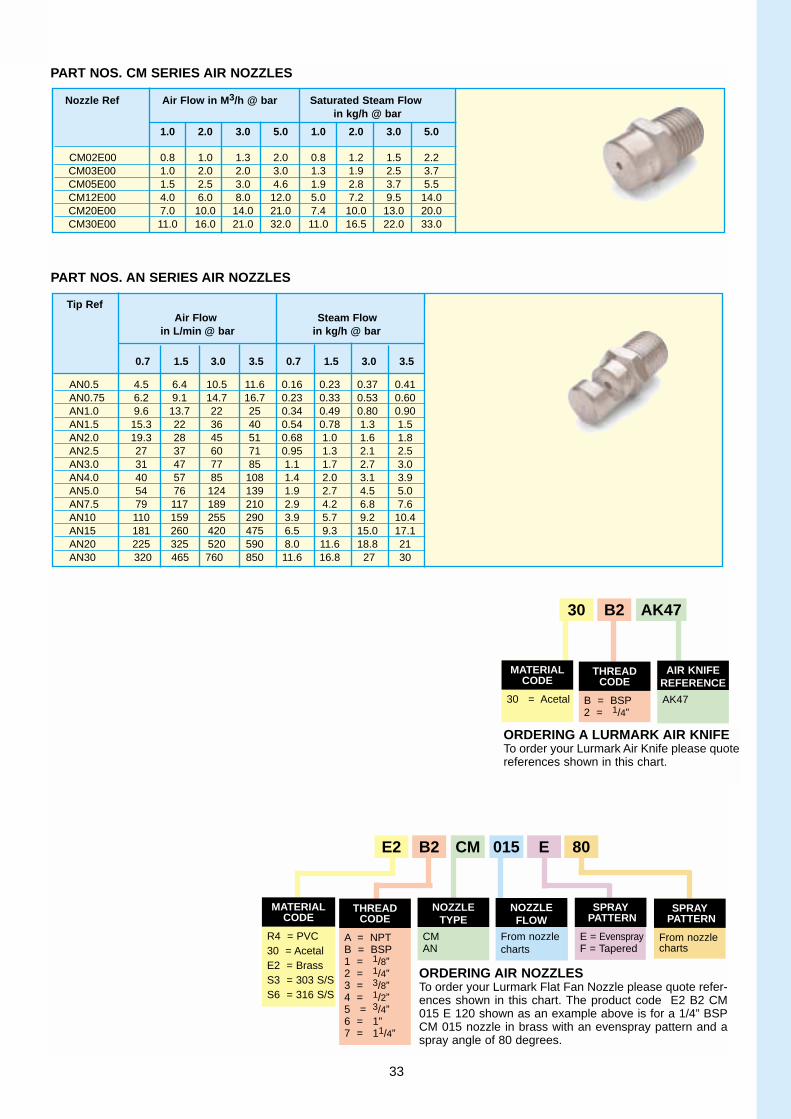
Nozzle Ref Air Flow in M 3/h @ bar Saturated Steam Flow in kg/h @ bar
1.0 2.0 3.0 5.0 1.0 2.0 3.0 5.0
CM02E00 0.8 1.0 1.3 2.0 0.8 1.2 1.5 2.2CM03E00 1.0 2.0 2.0 3.0 1.3 1.9 2.5 3.7CM05E00 1.5 2.5 3.0 4.6 1.9 2.8 3.7 5.5CM12E00 4.0 6.0 8.0 12.0 5.0 7.2 9.5 14.0CM20E00 7.0 10.0 14.0 21.0 7.4 10.0 13.0 20.0CM30E00 11.0 16.0 21.0 32.0 11.0 16.5 22.0 33.0
PART NOS. CM SERIES AIR NOZZLES
PART NOS. AN SERIES AIR NOZZLES
Tip RefAir Flow Steam Flow
in L/min @ bar in kg/h @ bar
0.7 1.5 3.0 3.5 0.7 1.5 3.0 3.5
AN0.5 4.5 6.4 10.5 11.6 0.16 0.23 0.37 0.41AN0.75 6.2 9.1 14.7 16.7 0.23 0.33 0.53 0.60AN1.0 9.6 13.7 22 25 0.34 0.49 0.80 0.90AN1.5 15.3 22 36 40 0.54 0.78 1.3 1.5AN2.0 19.3 28 45 51 0.68 1.0 1.6 1.8AN2.5 27 37 60 71 0.95 1.3 2.1 2.5AN3.0 31 47 77 85 1.1 1.7 2.7 3.0AN4.0 40 57 85 108 1.4 2.0 3.1 3.9AN5.0 54 76 124 139 1.9 2.7 4.5 5.0AN7.5 79 117 189 210 2.9 4.2 6.8 7.6AN10 110 159 255 290 3.9 5.7 9.2 10.4AN15 181 260 420 475 6.5 9.3 15.0 17.1AN20 225 325 520 590 8.0 11.6 18.8 21AN30 320 465 760 850 11.6 16.8 27 30
30 = Acetal B = BSP2 = 1/4”
AK47
ORDERING A LURMARK AIR KNIFETo order your Lurmark Air Knife please quote references shown in this chart.
E2 B2 CM 015 E 80
R4 = PVC30 = AcetalE2 = BrassS3 = 303 S/SS6 = 316 S/S
A = NPTB = BSP1 = 1/8”2 = 1/4”3 = 3/8”4 = 1/2”5 = 3/4”6 = 1”7 = 11/4”
CMAN
From nozzlecharts
E = EvensprayF = Tapered
From nozzlecharts
ORDERING AIR NOZZLESTo order your Lurmark Flat Fan Nozzle please quote refer-ences shown in this chart. The product code E2 B2 CM015 E 120 shown as an example above is for a 1/4” BSPCM 015 nozzle in brass with an evenspray pattern and aspray angle of 80 degrees.
33
30 B2 AK47
MATERIALCODE
THREADCODE
AIR KNIFEREFERENCE
SPRAYPATTERN
SPRAYPATTERN
NOZZLETYPE
NOZZLEFLOW
THREADCODE
MATERIALCODE

E2 B2 CM 015 E 80
R4 = PVC30 = Acetal90 = PVDFE2 = BrassS3 = 303 S/SS6 = 316 S/SS9 = 416 S/S
A = NPTB = BSP1 = 1/8”2 = 1/4”3 = 3/8”4 = 1/2”5 = 3/4”6 = 1”7 = 11/4”
F**CM*ANHPNSNXTC
From nozzlecharts
E = EvensprayF = Tapered
From nozzlecharts
MATERIALCODE
THREADCODE
NOZZLETYPE
NOZZLEREFERENCE
SPRAYPATTERN
SPRAYANGLE
S6 B1 GN 14 120
R1 = PolypropyleneR4 = PVC30 = Acetal90 = PVDFE2 = BrassS3 = 303 S/SS6 = 316 S/S
A = NPTB = BSP1 = 1/8”2 = 1/4”3 = 3/8”4 = 1/2”5 = 3/4”6 = 1”7 = 11/4”
TNFPL*GN*FN*FCX*Please suffix with‘F’ if female threadrequired.
From nozzlecharts
From nozzlecharts
MATERIALCODE
THREADCODE
NOZZLETYPE
NOZZLEREFERENCE
SPRAYANGLE
R4 B2 H 2 70
R1 = PolypropyleneR4 = PVC30 = AcetalE2 = BrassS3 = 303 S/SS6 = 316 S/S
A = NPTB = BSP1 = 1/8”2 = 1/4”3 = 3/8”4 = 1/2”5 = 3/4”6 = 1”7 = 11/4”
HAFAFHVH*HCX*Please suffix with‘F’ if female threadrequired.
From nozzlecharts
From nozzlecharts
MATERIALCODE
THREADCODE
NOZZLETYPE
NOZZLEREFERENCE
SPRAYANGLE
S6 B2 VP L C50 F
S3 = 303 S/SS6 = 316 S/S
B = BSP2 = 1/4”
VP X =Pneumatic
twin inletL =Pneumatic
single inletBlank = stan-dard body
Fluid and aircap as Vaprotables
A = blank plug D = manual
cw/shut-offF = Pneumatic
c/w shut -off
MATERIALCODE
THREADCODE
NOZZLETYPE
BODY COMBINATION SHUTOFF
ORDERING FLAT FANNOZZLESTo order your Lurmark FlatFan Nozzle please quote ref-erences shown in this chart.The product code E2B2CM015E120 shown as an exam-ple above is for a 1/4” BSPCM 015 nozzle in brass withan evenspray pattern and aspray angle of 80 degrees.Please note all straight jetsshould be ordered as E00spray pattern.
ORDERING FULL CONE NOZZLESTo order your Lurmark FlatFan Nozzle please quotereferences shown in thischart. The product code S6B1GN14-120 shown as anexample above is for a 1/8”BSPGN14 nozzle in 316stainless steel with a sprayangle of 120 degrees.
ORDERING HOLLOW CONE NOZZLESTo order your Lurmark FlatFan Nozzle please quotereferences shown in thischart. The product codeR4B2H2-70 shown as anexample above is for a 1/4”BSP H2 nozzle in PVCwith a spray angle of 70degrees.
ORDERING AIR ATOMISING NOZZLESTo order your Lurmark AirAtomising Nozzle pleasequote references shown inthis chart. The product codeS9B2VPLC50F shown asan example above is for a1/4” Vapro jet with a pneu-matic body with a singleinlet c/w shut-off in nickelplated brass with an air andfluid cap combination ofC50.
*Please suffix with ‘F’ if femalethread required. Default (blank)= male thread.
**Please quote - when ordering F Series nozzles, fornozzle type.
34
-
-
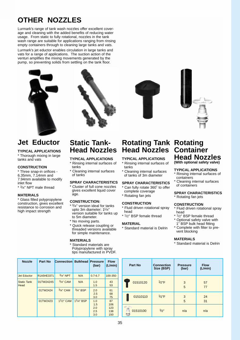
Jet EductorTYPICAL APPLICATIONS* Thorough mixing in largetanks and vats
CONSTRUCTION* Three snap-in orifices -6.35mm, 7.14mm and7.94mm available to modifyinlet flow* 3/4" NPT male thread
MATERIALS* Glass filled polypropyleneconstruction, gives excellentresistance to corrosion andhigh impact strength
Static Tank-Head NozzlesTYPICAL APPLICATIONS* Rinsing internal surfaces of
tanks* Cleaning internal surfaces
of tanks
SPRAY CHARACTERISTICS* Cluster of full cone nozzles
gives excellent liquid coverage.
CONSTRUCTION:* 3/4" version ideal for tanks
upto 3m diameter; 11/4"version suitable for tanks upto 5m diameter.
* No moving parts.* Quick release coupling or
threaded versions availablefor simple maintenance.
MATERIALS* Standard materials are
Polypropylene with spraytips manufactured in PVDF.
Rotating TankHead NozzlesTYPICAL APPLICATIONS* Rinsing internal surfaces of
tanks* Cleaning internal surfaces
of tanks of 3m diameter
SPRAY CHARACTERISTICS* Can fully rotate 360˚ to offer
complete coverage* Rotating fan jets
CONSTRUCTION* Fluid driven rotational spray
head* 1/2" BSP female thread
MATERIAL* Standard material is Delrin
RotatingContainerHead Nozzles(With optional safety valve)
TYPICAL APPLICATIONS* Rinsing internal surfaces of
containers* Cleaning internal surfaces
of containers
SPRAY CHARACTERISTICS* Rotating fan jets
CONSTRUCTION* Fluid driven rotational spray
head* 1/2" BSP female thread* Optional safety valve with
1” BSP bulk head fitting* Complete with filter to pre-
vent blocking
MATERIALS* Standard material is Delrin
OTHER NOZZLESLurmark's range of tank wash nozzles offer excellent cover-age and cleaning with the added benefits of reducing waterusage. From static to fully rotational, nozzles in the tankwash range are suitable for applications ranging from rinsingempty containers through to cleaning large tanks and vats.Lurmark's jet eductor enables circulation in large tanks andvats for a range of applications. The suction action of theventuri amplifies the mixing movements generated by thepump, so preventing solids from settling on the tank floor.
Nozzle Part No Connection Bulkhead Pressure Flow(bar) (L/min)
Jet Eductor R1A5HE3371 3/4” NPT N/A 0.7-6.7 100-350
Static Tank 01TW2424S 3/4” CAM N/A 1.0 43Head 1.5 53
01TW2424 3/4” CAM 3/4” BSP 2.0 612.5 683.0 75
01TW2423 11/2” CAM 11/4” BSP 1.0 871.5 1062.0 1232.5 1383.0 150
Part No Connection Pressure FlowSize (BSP) (bar) (L/min)
01510120 1/2”F 3 575 77
01510110 1/2”F 3 245 31
01510100 1/2” n/a n/a
35

Nozzle MaintenanceSpray nozzles require regu-lar inspection,maintenanceand cleaning just like anyother type of productionequipment. The amount ofmaintenance requireddepends on your particularprocess and environment. Generally spray nozzlesexceeding 10% of flow rateshould be replaced. A visualcheck should be carried out for physical damage and
spray patternation everyscheduled shutdown or sooner, depending on the chemi-cals being used.1. CloggingDirt or other particlesbecoming lodged in the orifice which causes flowrestriction and affects thespray patternation.2. Erosion/WearEnlarging of the nozzle orifice due to the gradual removal of material over a
period of time. This will have
a direct effect on flow, pres-sure and the spray pattern willdeteriorate.3. Corrosion. Breakdown of the nozzlematerial due to the surround-ing environment usually dueto chemical attack.4. Temperature DamageExcess heat exposure of nozzle material not suitablefor high temperature applica-tions will result in a significantreduction in performance.5. Caking. Build up of dried solidsaround the orifice or surfaceof the nozzle due to over-spray or evaporation, willreduce nozzle performanceby obstruction.6. Assembly MistakesFollowing a cleaning processthe nozzles may not be putback together correctly withlost gaskets, missing swirlplates or over-tighteningbeing the main problems. Thisresults in leaking or poorspray patternation.Accidental DamageOrifice damage causedthrough scratching or cleaningby using the incorrect toolsmay cause flow and patterna-tion problems.
CARE OFNOZZLES
Problem Probable Causes Remedy
Restriction to flow Dirt or other Particles becoming Clean with an air line or soak in appropriatelodged in nozzle orifice solution overnight
Clean FilterCaking as a build up of dried solids. ReplaceAccidental Damage caused through Replacecareless cleaning or reassembly
Spray patternation Dirt or other particles lodged in the Clean with an air line or soak in appropriateincorrect nozzle orifice solution overnight
Clean FilterGeneral nozzle wear ReplaceTemperature Decrease/Increase temperature
Increase/Decrease pressureCorrosion ReplaceAccidental Damage Replace
Increased nozzle General nozzle wear Replace if above 10% of Theoretical flow flow rate
Corrosion ReplaceTemperature Lower/Increase temperature
Increase/Decrease pressureAccidental Damage Replace
1
2
26
3
5
2
1
4
1
2
36

Section 3Nozzle Accessories
The Lurmark range of nozzle holders, filters and cap nuts offer all the
products for quick and easy installation of both metal cut and plastic tips.
Making spraying more efficient worldwide
37

NOZZLE TIPASSEMBLYFor quick and easy installa-tion of spray tips, Lurmarkcan provide a four piece system consisting of inter-changeable nozzle bodiesnozzle filters, spray tips andcap nuts, all designed to suityour specific application.Available in a range of materi-als to suit both moulded andmetal spray tips, the Lurmarksystem reduces downtimewhen changing tips to produce different spray patterns or replacing wornspray nozzles.
NOZZLEHOLDERSAvailable as threaded, spliteyelet, clamp style, swiveland adjustable ball typedesign, Lurmark’s nozzleholders are available in arange of thread types andmaterials.All connections are BSPthread, however, NPT andUNF threads are available onrequest.
CONNECTION OUTLET MATERIAL Part Number1/8” BSPT 3/8” BSP Polyacetal 27-Q24701/4” BSPT 3/8” BSP Polyacetal 27-Q24711/8” BSPT 3/8” BSP Brass 241010-M1/4”BSPT 3/8” BSP Brass 2410104M3/8” BSPT 3/8” BSP Brass 2410103M1/8” BSPT 3/8” BSP PVDF 27PQ24701/4” BSPT 3/8” BSP PVDF 27PQQ24711/8” BSPT 3/8” BSP Stainless Steel (303) 311010-M1/4” BSPT 3/8” BSP Stainless Steel (303) 3110104M3/8” BSPT 3/8” BSP Stainless Steel (303) 3110103M
CONNECTION OUTLET MATERIAL Part Number1/8”BSP 3/8” BSP Polyacetal 27-Q24741/4” BSP 3/8” BSP Polyacetal 27-Q24751/8” BSPT 3/8” BSP Brass 241010FM 1/4” BSP 3/8” BSP Brass 241014FM1/4” BSPT 3/8” BSP Brass 241010FM3/8” BSP 3/8” BSP Brass 241013FM 1/4” BSP 3/8” BSP Stainless Steel (303) 311014FM1/4” BSPT 3/8” BSP Stainless Steel (303) 311010FM
CLAMP SIZE OUTLET MATERIAL Part Number
1/2” Clamp 3/8” BSP(M) Polypropylene 271016123/4” Clamp 3/8” BSP(M) Polypropylene 271016341/2” Rectangular 3/8” BSP(M) Polypropylene 271017123/4” Rectangular 3/8” BSP(M) Polypropylene 271017341/2” Rectangular 1/8” BSP(F) Polypropylene 701Q19751/2” Rectangular 1/4” BSP(F) Polypropylene 702Q19753/4” Rectangular 1/8” BSP(F) Polypropylene 703Q19753/4” Rectangular 1/4” BSP(F) Polypropylene 704Q19751/2” Clamp 3/8” BSP(M) Polypropylene 25DC1083*3/4” Clamp 3/8” BSP(M) Polypropoyene 25DC1086*1/2” Rectangular 3/8” BSP(M) Polypropylene 25DC1084*3/4” Rectangular 3/8” BSP(M) Polypropylene 25DC1087*
CONNECTION OUTLET MATERIAL Part Number
Single-Standard 1/4” BSP(F) 3/8” BSP(M) Brass 241019SS1/4” BSP(F) 3/8” BSP(M) Polyacetal 014040703/8” BSP(F) 3/8” BSP(M) Polyacetal 01404080
Double - Standard 1/4” BSP(F) 3/8” BSP(M) Polyacetal 241019DS1/4“ BSP(F) 3/8” BSP(M) Polyacetal 014041703/8” BSP(F) 3/8” BSP(M) Polyacetal 01404180
Single - Complete with Shut-Off 1/4” BSP(F) 3/8” BSP(M) Brass 27302492
Double- Complete with Shut-Off1/4” BSP(F) 3/8” BSP(M) Polyacetal 27302489
THREADED HOLDERS - STANDARD - MALE VERSION
THREADED HOLDERS - STANDARD - FEMALE VERSION
THREADED HOLDERS - CLAMP STLYE
SWIVEL HOLDERS
SIZE MATERIAL Part Number
1/4” BSP Brass E2Q12753/8” BSP Polypropylene (Grey) 251032GY3/8” BSP Polypropylene (White) 251032WH3/8” BSP Polypropylene (Black) 251032BL3/8” BSP Brass 241030 - -3/8” BSP 303 Stainless Steel 311030SS3/4” BSP Brass B1E5Q34743/4” BSP Polypropylene 14EQ2185
1” BSP Brass 28-Q2142
CAP NUTS
Standard Threaded Holders(left) male - (right) female
Clamp Style Threaded Holders(left) Standard Clamp - (centre) Rectangular Clamp - (right) DCV
Swivel Holders(left) Single-Standard - (right) Double Standard
Swivel Holders(left) Double complete with shut-off - (right) Single complete with shut-off
38
* c/w DCV at 1 bar
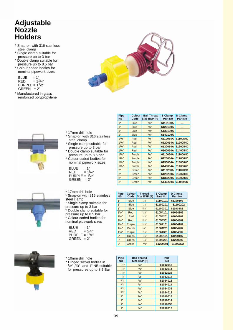
AdjustableNozzleHolders* Snap-on with 316 stainless
steel clamp* Single clamp suitable for
pressure up to 3 bar* Double clamp suitable for
pressure up to 8.5 bar* Colour coded bodies for
nominal pipework sizes
BLUE = 1”RED = 11/4”PURPLE = 11/2”GREEN = 2”
* Manufactured in glass reinforced polypropylene
Pipe Colour Ball Thread S Clamp D ClampNB Code Size BSP (F) Part No Part No
1” Blue 1/8” 6110100A —1” Blue 1/4” 6120100A —1” Blue 3/8” 6130100A —1” Blue 1/2” 6140100A —11/4” Red 1/8” 6110054A 6110054D11/4” Red 1/4” 6120054A 6120054D11/4” Red 3/8” 6130054A 6130054D11/4” Red 1/2” 6140054A 6140054D11/2” Purple 1/8” 6110064A 6110064D11/2” Purple 1/4” 6120064A 6120064D11/2” Purple 3/8” 6130064A 6130064D11/2” Purple 1/2” 6140064A 6140064D2” Green 1/8” 6110200A 6110200D2” Green 1/4” 6120200A 6120200D2” Green 3/8” 6130200A 6130200D2” Green 1/2” 6140200A 6140200D
Pipe Colour Thr ead S Clamp D ClampNB Code Size BSP (F) Part No Part No
1” Blue 1/8” 61100101 611001021” Blue 1/4” 61100201 611002021” Blue 3/8” 61100301 6110030211/4” Red 1/8” 61054101 6105410211/4” Red 1/4” 61054201 6105420211/4” Red 3/8” 61054301 6105430211/2” Purple 1/8” 61064101 6106410211/2” Purple 1/4” 61064201 6106420211/2” Purple 3/8” 61064301 610643022” Green 1/8” 61200101 612001022” Green 1/4” 61200201 612002022” Green 3/8” 61200301 61200302
Pipe Ball Thread PartNB Size BSP (F) No
1/2” 1/8” 610120181/2” 1/4” 610120141/2” 3/8” 610120381/2” 1/2” 610120123/4” 1/8” 610340183/4” 1/4” 610340143/4” 3/8” 610340383/4” 1/2” 610340121” 1/8” 610100181” 1/4” 610100141” 3/8” 610100381” 1/2” 61010012
* 17mm drill hole* Snap-on with 316 stainless
steel clamp* Single clamp suitable for
pressure up to 3 bar* Double clamp suitable for
pressure up to 8.5 bar* Colour coded bodies for
nominal pipework sizes
BLUE = 1”RED = 11/4”PURPLE = 11/2”GREEN = 2”
* 17mm drill hole* Snap-on with 316 stainlesssteel clamp* Single clamp suitable forpressure up to 3 bar* Double clamp suitable forpressure up to 8.5 bar* Colour coded bodies fornominal pipework sizes
BLUE = 1”RED = 11/4”PURPLE = 11/2”GREEN = 2”
* 10mm drill hole* Hinged swivel bodies in
1/2” ,3/4” and 1” NB suitablefor pressures up to 8.5 Bar
39

Ball Check Filter in Acetal withstainless steel screen. Provideslimited anti-drip facility for non-DCV nozzles
Fitted with nitrile balls
30 mesh (coarse), whitePart No. 3210053050 mesh (medium), bluePart No. 32100550100 mesh (fine),greenPart No. 32100510200 mesh (v.fine), yellowPart No. 32100520
CUP FILTER(COPPER FLANGE)
Cup Filter with copper flangeand s/steel screen
30 mesh (coarse)Part No. 3210063050 mesh (medium)Part No. 32100650100 mesh (fine)Part No. 32100610200 mesh (v.fine)Part No. 32100620
CUP FILTER (NYLONFLANGE)Cup Filter with nylon flange andstainless steel screen
30 mesh (coarse)Part No. 3230A24550 mesh (medium) Part No. 3250A245100 mesh (fine)Part No 3210A245
STANDARD FILTER
Standard Nozzle Filter in Acetalwith stainless steel screen.
50 mesh (medium), bluePart No. 32100050100 mesh (fine), greenPart No. 32100010200 mesh (v.fine) yellowPart No. 32100020
CUP FILTER IN MOULDEDPOLYPROPYLENE.
30 mesh (coarse) whitePart No. 3210063P50 mesh (medium) bluePart No. 3210065P
BALL CHECK FILTERS (ANTI-DRIP)
SPRAY NOZZLESPlease refer to Section 2for details of Lurmark’scomplete range of spraytips and nozzles
NOZZLE FILTERSCompatible with themost common types ofnozzle holders,Lurmark’s range of nozzle filters are colourcoded for easy identifi-cation. The ball checkfilters provide an anti-drip facility in theabsence of diaphragmcheck valves.
MESH REFERENCE CHART
Mesh Mesh Wire Ratio of MaterialOpening Diameter Mesh Opening(Microns) (Microns) Surface to
MeshTotal
Surface%
16 980 490 44.4 Polypropylene
16 1320 220 73.3 Stainless Steel
32 500 320 37.1 Polypropylene
32 594 200 55.3 Stainless Steel
50 365 140 50.8 Stainless Steel
80 229 80 55.7 Stainless Steel
100 173 80 46.4 Stainless Steel
120 134 70 43 Poliammide
120 144 70 45.4 Stainless Steel
150 96 65 35 Poliammide
150 114 70 42.4 Stainless Steel
200 80 50 37 Poliammide
200 76 50 36.2 Stainless Steel
40

Section 4Spray Accessories
The following pages give details of a rangeof spray accessories from in-line filters to
pumps and valves, pressure gauges and a multiplicity of fittings.
You will find that there’s everything youneed to maintain your spraying
operation at maximum efficiency.And they all have the backing of the
Lurmark technical service team.
Making spraying more efficient worldwide
41

PUMPSLurmark has a full rangeof pumps, suitable for avariety of industrial appli-cations. Some of themore common modelswith their features andbenefits are shown on thefollowing pages. This listis by no means exhaus-tive, if you can not findthe information you need,or would like additionaldata, then contact ourtechnical experts for moreinformation.
Pump Type Features Typical Applications
CENTRIFUGAL
DIAPHRAGM
ROLLER
FLEXIBLEIMPELLER
GEAR
PLUNGER
High volume. Smooth non-pulsating flow Lowmaintenance Compact size Easily disassembled Easy installationNon-positive displacementLow pressureSelf priming availableNon clogging
Self priming Handles abrasives and corrosives Positive displacement Long life Medium to high pressure
Easy maintenance Operates at PTO speeds Low to medium flow ratesLow to medium pressure Positive displacement
Self priming Pumps thin and viscous liquids One moving part High capacity - deliver greater flow for weightand size in comparison to other pump typesHigh and low speeds possibleLow pressure
Self priming High pressure possible Pumps viscous liquids
Low to medium flow rates Operates at high pressures Operates at PTO speeds
Parts washers Solvent recovery Water treatment General transfer Metal finishing Chemical processingFiltration Booster systems Marine cooling Agricultural spraying
Agricultural sprayingGeneral transferHorticultural spraying
Hot oil transfer Oil management Agricultural spraying Lawn care
Ink transfer General transfer Wash down Sump cleaning Barrel emptyingEmulsions and shear sensitive fluids Handles abrasive solids
Chemical metering Solvent recovery Filtration Filling equipment Water treatment Pulp and paper processes Brine injection
Car washing Industrial cleaners Parts washers
42

PUMP SERIES MAX FLOW MAX MAX PORTS DRIVE TYPE MAX NUMBER OF SEAL ORTYPE (rate L/min) PRESSURE SIZE rpm DIAPHRAGMS DIAPHRAGM MATERIAL
bar Inlet Outlet
Centrifugal Aqua Tiger 71 0.48 3/4 3/4 electric VitonAqua Tiger SS 71 0.48 3/4 3/4 electric Viton9940 499 2.4 11/2 11/2 Viton9200/9500 348 5.5 11/2 11/4 petrol engine Viton9000 350 5.5 11/2 11/4 Viton9000 440 5.5 11/2 11/4 gear Viton9300P 310 5.8 11/2 11/4 hydraulic motor Viton9000SP 613 8.6 2 2 gear Viton9300 790 8.9 2 11/2 hydraulic motor Viton1500SP 586 9.3 2 2 Honda Petrol Viton1500 567 9.6 2 11/2 Honda Petrol Viton9200SP 600 10.3 11/2-2 11/4-2 Viton9300SP 673 10.6 2 2 hydraulic motor Viton9200 510 12 11/2 11/4 Viton
Diaphragm 2088-953-233 5 1 1/2 1/2 dc/ac motors 3 Viton, Buna8000-542-296 2 2 3/8 1/2 dc/ac motors 3 Viton, Buna, EPDM8000-542-136 2 2 3/8 1/2 dc/ac motors 3 Viton, Buna, EPDM8000-234-155 3 2 3/8 1/2 dc/ac motors 3 Viton, Buna, EPDM8000-043-235 4 2 3/8 1/2 dc/ac motors 3 Viton, Buna, EPDM8000-802-273 4 2 3/8 1/2 dc/ac motors 3 Viton, Buna, EPDM8000-043-295 3 2.5 3/8 1/2 dc/ac motors 3 Viton, Buna, EPDM8000-212-246 2 3 3/8 1/2 dc/ac motors 3 Viton, Buna, EPDM2088-562-144 2 4 1/2 1/2 dc/ac motors 3 Viton, Buna8000-772-233 2 5 3/8 1/2 dc/ac motors 3 Viton, Buna, EPDM2088-474-144 1 6 1/2 1/2 dc/ac motors 3 Viton, Buna2088-403-143 1.8 6 1/2 1/2 dc/ac motors 3 Viton, Buna2088-403-144 2 7 1/2 1/2 dc/ac motors 3 Viton, Buna2088-403-143 1 8 1/2 1/2 dc/ac motors 3 Viton, Buna115bp/1000 94 15 13/4 1 splined shaft 1000 3 Desmopan,EPDM,Viton,Buna70bp 72 20 1 1 splined shaft 550 2 Desmopan,EPDM,Viton,Buna115bp 114 20 11/4 1 splined shaft 550 3 Desmopan,EPDM,Viton,Buna135bp 132 20 11/4 1 splined shaft 550 3 Desmopan,EPDM,Viton,Buna160bp 161 20 11/4 11/4 splined shaft 550 4 Desmopan,EPDM,Viton,Buna185bp 180 20 13/4 11/4 splined shaft 550 4 Desmopan,EPDM,Viton,Buna250bp 250 20 13/4 11/4 splined shaft 550 6 Desmopan,EPDM,Viton,Buna280bp 282 20 13/4 11/4 splined shaft 550 6 Desmopan,EPDM,Viton,Buna370bp(twin) 371 20 21/2 13/4 splined shaft 550 8 Desmopan,EPDM,Viton,Buna
Flexible Impeller RG102 132 1.4 1 1 3600 NitriteRG30G 41 1.7 1/2 1/2 3600 NitriteRG50G 110 1.7 3/4 3/4 3600 NitriteMRS9901 140 1.7 3/4-11/4 3/4-11/4 3450 VitonMRB9901 142 1.7 1/2-1 1/2-1 3450 Nitrite
Roller Vane 4001N-E2H 37 4 3/4 3/4 electric 1600 Viton4101N-E2H 22 7 3/4 3/4 electric 1600 Viton4101X-E2H 28 7 3/4 3/4 electric 1900 Viton40101C 26 10 3/4 3/4 2600 Viton4101N 26 10 3/4 3/4 2600 Viton4001C 34 10 3/4 3/4 1800 Viton4001N 34 10 3/4 3/4 1800 Viton1502C 227 10 11/2 11/2 Available with 1000 Buna-N
PTO Adaptor1502N 227 10 11/2 11/2 1000 Buna-N1200C 272 10 11/2 11/2 Available with 800 Buna-N
PTO Adaptor1700C 204 13 1 1 1000 Viton1700N 204 13 1 1 1000 Buna-N6500C 74 21 3/4 3/4 Available with 1200 Viton
PTO Adaptor6500N 74 21 3/4 3/4 1200 Viton7560C 81 21 3/4 3/4 Available with 1000 Viton
PTO Adaptor7560N 81 21 3/4 3/4 1000 Viton
PUMP SELECTION GUIDE
Continued overleaf
LOW PRESSURE PUMPS
43
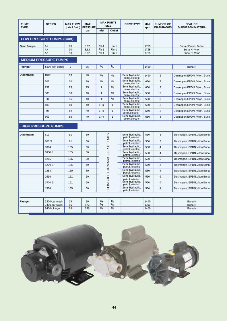
PUMP SERIES MAX FLOW MAX MAX PORTS DRIVE TYPE MAX NUMBER OF SEAL OR TYPE (rate L/min) PRESSURE SIZE rpm DIAPHRAGMS DIAPHRAGM MATERIAL
bar Inlet Outlet
Gear Pumps AK 90 8.62 3/8-1 3/8-1 1725 Buna-N.Viton, TeflonAK 90 8.62 3/8-1 3/8-1 1725 Buna-N, VitonAK 90 8.62 3/8-1 3/8-1 1725 Buna-N, Viton
Plunger 5300-twin piston 9 35 1/2 1/2 1450 Buna-N
Diaphragm DUE 13 20 3/4 3/8 Semi hydraulic, 1450 2 Desmopan,EPDN, Viton, Bunapetrol,electric
202 20 20 3/4 3/8 Semi hydraulic, 650 2 Desmopan,EPDN, Viton, Bunapetrol,electric
252 25 25 1 1/2 Semi hydraulic, 650 2 Desmopan,EPDN, Viton, Bunapetrol,electric
303 30 40 1 1/2 Semi hydraulic, 550 3 Desmopan,EPDN, Viton, Bunapetrol,electric
30 35 40 1 1/2 Semi hydraulic, 550 2 Desmopan,EPDN, Viton, Bunapetrol,electric
403 40 40 11/4 1 Semi hydraulic, 550 3 Desmopan,EPDN, Viton, Bunapetrol,electric
50 52 40 11/4 1 Semi hydraulic, 550 2 Desmopan,EPDN, Viton, Bunapetrol,electric
503 55 40 11/4 1 Semi hydraulic, 550 3 Desmopan,EPDN, Viton, Bunapetrol,electric
Diaphragm 813 81 50 Semi hydraulic, 550 3 Desmopan, EPDN,Viton,Bunapetrol, electric
800 S 81 50 Semi hydraulic, 550 3 Desmopan, EPDN,Viton,Bunapetrol, electric
1064 105 50 Semi hydraulic, 550 4 Desmopan, EPDN,Viton,Bunapetrol, electric
1000 S 105 50 Semi hydraulic, 550 4 Desmopan, EPDN,Viton,Bunapetrol, electric
1265 126 50 Semi hydraulic, 550 5 Desmopan, EPDN,Viton,Bunapetrol, electric
1200 S 126 50 Semi hydraulic, 550 5 Desmopan, EPDN,Viton,Bunapetrol, electric
1254 130 50 Semi hydraulic, 550 4 Desmopan, EPDN,Viton,Bunapetrol, electric
1516 151 50 Semi hydraulic, 550 6 Desmopan, EPDN,Viton,Bunapetrol, electric
1500 S 151 50 Semi hydraulic, 550 6 Desmopan, EPDN,Viton,Bunapetrol, electric
1554 155 50 Semi hydraulic, 550 4 Desmopan, EPDN,Viton,Bunapetrol, electric
Plunger 2300-car wash 15 80 3/8 1/2 1450 Buna-N2400-car wash 15 172 3/4 1/2 1100 Buna-N2400-plunger 26 248 3/4 1/2 1450 Buna-N
LOW PRESSURE PUMPS (Cont)
MEDIUM PRESSURE PUMPS
HIGH PRESSURE PUMPS
44
CO
NS
ULT
LUR
MA
RK
FO
R D
ETA
ILS

Foot Filters
* Ideal for providing first stageof filtration.*Coarse mesh prevents verylarge particles being drawnfrom the liquid storage tank.* Size and shape allow easypositioning without damagingthe tank walls.
CompactFoot Filters
Line Filters
1/2” & 3/4” LINE FILTERSAND SPARES
* 1/2” and 3/4” BSP threads* Max. working pressure 14 bar* Filtering capacity 80 -100
L/min * Cartridge Ø 38 x 89 mm* Fixing points on both sides* Polypropylene body* EPDM gaskets.
Components Part Numbers
1/2” Hood 2101BH123/4” Hood 2101BH34Bowl 2101BOBOHood O ring 2101BOTOElement O ring x 2 2101BOEO 32# Element 2112B03050# Element 2113B05080# Element 2113B057200# Element 2113B200
1” LINE FILTERS ANDSPARES
* 1” BSP threads * Max. working pressure 14 bar* Filtering capacity 150 - 160
L/min * Cartridge Ø 38 x 125 mm* Fixing points on both sides* Polypropylene body * EPDM gaskets.
Components Part Numbers1” Hood 2101BH10Bowl 213224000-020Hood O ring 21G11017Element O ring x 2 2101BOEORetaining nut 213224000-05032# Element 2132300250# Element 2132300380# Element 213230035
A B C Part mm mm mm Number
19 60 47 0830201919 60* 47 08302019.115 100 54 0830211520 100 54 0830212022 100 54 0830212225 100 54 0830212525 125 76 0830222530 125 76 0830223030 150 96 0830233035 150 96 0830233540 150 96 0830234050 150 96 08302350
G11/4 150 96 08302-05M(BSP)
Port Mesh Part BSP (M) Number
11/4” 16 0831A36711/2” 16 0831A3682” 16 08325A369
Port Part No F Screen Type
Filter Effective AreaLength
(BSP) (mm) cm 2 in 2
2 0 N 6 2 2 3 0 1/2 32 mesh 21 30
4.7
2 0 N 6 2 2 5 0 1/2 50 mesh 21 28
4.3
2 0 N 6 2 2 8 0 1/2 80 mesh 21 25
3.9
2 0 N 6 2 2 2 0 1/2 200 mesh 21
20 3.1
PortPart No F Screen Type
Filter Effective Area
(BSP) length
cm 2 in 2mm
2 0 N 6 2 4 3 0 1 32 mesh 23 41
6.4
2 0 N 6 2 2 5 0 1 50 mesh 23 38
PART NOS. 1” LINE FILTERS
*With non-return valve
FILTERSTo prevent pump damage and blockednozzles, Lurmark canprovide a range of filters to suit all applica-tions. Normally, filtra-tion should be appliedin stages, ranging from,coarse in the liquidreservoir through tofine just before the nozzle. Please see page40 for details of nozzlefilters.Mesh sizes can be varied depending onthe flow rate of the liq-uid being sprayed.
*Polypropylene body and filter mesh
A
B
C
45
PART NOS. 1/2” AND 3/4” LINE FILTERS

Line Filters11/4” & 1 1/2” LINE FILTERSSTANDARD FLUSHING ANDSPARES
* 11/4” and 11/2” BSP threads* Max. working pressure 15 bar* Filtering capacity 200 - 280
L/min * Cartridge Ø 58 x 210 mm* Fixing points on both sides* Polypropylene body * EPDM gaskets* Flushing option has a ball
valve fitted to the bottom ofthe bowl.
Components Part Numbers11/4” Hood 2101BH5411/2” Hood 2101BH64Bowl Flushing
213262300-020Bowl Standard
213262000-020Hood O ring 21G10090Element O ring (x2)
2101AOEORetaining Ring
213262000-05030# Element 21A6313050# Element 21A6315080# Element 21A63180200# Element 21A63200Washer Seal 01WSHR02Ball Valve (flush version)
56454133
Part No Part No Port Screen Effective Flushing Standard Size (F) Type Area
(BSP) cm2 sq.in
2 0 N F 6 2 5 3 0 2 0 N 6 2 5 3 0 11/4 32 mesh
115 17.9
2 0 N F 6 2 5 5 0 2 0 N 6 2 5 5 0 11/4 50 mesh
106 16.4
2 0 N F 6 2 5 8 0 2 0 N 6 2 5 8 0 11/4 80 mesh
115 18.0
2 0 N F 6 2 5 2 0 2 0 N 6 2 5 2 0 11/4 200 mesh
77 11.9 2 0 N F 6 2 6 3 0
PART NOS. 11/4” & 1 1/2” LINE FILTERS
46
Pipe andHose(Minimum length 1 metre)
Polypropylene PipeundrilledNB1/2” 51PP- 1/23/4” 51PP-3/4
PVC Pipe undrilled NB3/8” 51514101 1/4” 515141023/4” 515141031” 5151410411/4” 5151410511/2” 515141062” 51514107
Reinforced Rubber Hose NB 1/4” 50RHID143/8” 50RHID381/2” 50RHID125/8” 50RHID583/4” 50RHID341” 50RHID1011/4” 50RHID5411/2” 50RHID6421/2” 50RHID25
PVC Clear Hose NB 1/4” 51W10X143/8” 51W10X381/2” 51W10X125/8” 51W10X583/4” 51W10X341” 51W10X10
Note: NB denotes NominalBore of pipe
PVC Braided HoseNB 3/8” 52B-38ID1/2” 51B-12ID5/8” 51B-58ID3/4” 51B-34ID1” 51B-10ID
Suction Hose (Heliflex)NB 1” 50HFID1011/4” 50HFID54
11/2” 50HFID642” 50HFID2021/2” 50HFID25
Cement & Cleaner
1/4” litre Solvent Cement(complete with brush)
015540051/2” litre Pipe Cleaner
01554004
PIPES ANDFITTINGSMaintaining a leak-free andsmooth liquid flow from thesource to the nozzle isessential for any spray sys-tem. To help you achieve thisin your application, Lurmarkoffer a complete range ofhigh quality pipes and fittingsmanufactured in a widerange of materials. When selecting pipework, itis important to remember thatpressure loss will occur.Tables shown on this pagewill help you build this factorinto your system.
Pipe Size (NB) Inches 1/2” 3/4” 1” 11/4” 11/2” 2” 3 ” 4” 6”
Maximum Flow L/Min at Zero Pressure 34.10 77.28 136.48 227.31 318.23 545.53 1227.45 2227.50 95000.71
Outside Diameter (Ins) for PVC Class 7 Pipe 0.84 1.05 1.32 1.66 1.90 2.38 3.50 4.50 6.63
Outside Diameter (mm) for PVC Class 7 Pipe 21.34 26.67 33.53 42.16 48.26 60.33 88.90 114.30 168.28
POLYPROPYLENEExcellent strength,Resistant to many corro-sive materials.Must be threaded or fusion welded. Tolerant to temperaturesof 100˚C and pressuresof 12 bar.
PVCHighly versatile. Can be glued, threadedor machined. Tolerant to5 bar.
NYLONVery durable. Can be used at low tem-peratures (ca 79˚C) andhigh pressure (ca 10 bar). Good chemical resist-ance.
Pipe Actual Std. Tee 45° Run ofStd.Elbow Globe GateSize Inside Through Std. Std.or Run Valve ValveStd. Diam. Side Elbow Tee
FRICTION LOSS THROUGH FITTINGS IN EQUIV-
47
1/8” 6.8 0.43 0.11 0.12 0.23 2.4 0.05
1/4” 9.2 0.67 0.15 0.20 0.34 3.4 0.06
1/2” 15.8 1.0 0.24 0.34 .52 5.7 0.11
3/4” 21 1.3 0.30 0.43 .64 7.07 0.13
1” 27 1.6 0.37 0.55 .79 9.08 0.17
11/4” 35 2.1 0.49 0.70 1.1 11.81 0.23
11/2” 41 2.5 0.58 0.82 1.2 13.81 0.26
2” 53 3.2 0.73 1.1 1.6 17.71 0.34
21/2” 63 3.8 0.88 1.3 1.9 21 0.40
3” 78 4.7 1.1 16 2.3 26 0.49
4” 102 6.2 1.4 2.1 3.1 34 0.64
6” 128 7.7 1.8 2.6 3.9 43 0.82
5’ 154 9.4 2.2 3.1 4.7 52 0.98

12
34
5
6
78
9
10
1112
1314
15
16
17 18

PolypropyleneFittingsMany polypropylene blackfittings can be used withthe following O-rings asthread sealant - hencethere is no longer a needto use PTFE tape.* Pleaserefer to table below.
*Do not seal those itemsmarked with an asterix with O-rings
Hexagonal Nipple (Black)
1/2” BSP 3525020203/4” BSP 3525020301” BSP 35250204011/4” BSP 35250205011/2” BSP 3525020602” BSP 352502070
Hexagonal Nipple(Grey)
1/2” BSP 35AT-2113/4” BSP 35AT-2121” BSP 35AT-21311/4” BSP 35AT-21411/2” BSP 35AT-2152” BSP 35AT-216
Hexagonal Nipple (Longthread)
1/2” BSP 352500211” BSP 3525004111/4" BSP 3500A345 11/2” BSP 3500A346 2" BSP 3500A347
HexagonalReducing Nipple (Black)
1/4" x 1/2” BSP 35240002 1/2” x 3/4” BSP 35240023 1/2” x 1" BSP 35240024 3/4” x 1" BSP 3500A350 1" x 11/4”BSP 3500A351 11/4" x 11/2” BSP 3500A352 11/2” x 2" BS 3500A353
HexagonalReducing Nipple (Grey)
1/4” x 3/8” BSP 27-Q24713/8” x 1/2” BSP 35AT21A01/2” x 3/4" BSP 35AT21A13/4” x 1” BSP 35AT21A21” x 11/4" BSP 3500A35111/4” x 11/2” BSP 3500A35211/2” x 2” BSP 3500A353
Back Nut (Black)
3/8” BSP 352050101/2” BSP 352050203/4” BSP 3500A5411" BSP 3500A54211/4" BSP 3500A54311/2” " BSP 3500A5442" BSP 3500A54521/2” BSP 35205080
Back Nut (Grey)
1/2” BSP 3500A5403/4” BSP 3500A5411” BSP 3500A54211/4” BSP 3500A54311/2” BSP 3500A5442” BSP 3500A545
Threaded Plug(Black)
1/4" BSP 352150013/8” BSP 352150101/ 2” BSP 352150203/4”BSP 352150301" BSP 3521504011/4 BSP 35215050
Threaded Plug c/w washer (Grey)
1/4” BSP 3500FP/13/8” BSP 3500FP/21/2” BSP 3500FP/33/4” BSP 3500FP/41” BSP 3500FP/5
Threaded Blanking Cap (Black)
3/8” BSP 3500A554 1/2” BSP 3500A555 3/4” BSP 3500A556 1" BSP 3500A557 11/4" BSP 3500A558 11/2” BSP 3500A559 2" BSP 3500A560
Threaded Blanking Cap (Grey)
3/8” BSP 3500A5541/2” BSP 3500A5553/4” BSP 3500A5561” BSP 3500A55711/4” BSP 3500A55811/2” BSP 3500A5592” BSP 3500A560
Equal and UnequalThreaded Tees (Black)
1/2” BSP (F) 3513020203/4” BSP (F) 3513020301" BSP (F) 35130204011/4" BSP (F) 35130205011/2” BSP (F) 3513020602" BSP (F) 351302070
Equal ThreadedTees (Grey)
3/8” BSP (F) 358240381/2” BSP (F) 358240123/4” BSP (F) 358240341” BSP (F) 3582401011/4” BSP (F) 3582405411/2” BSP (F) 358240642” BSP (F) 35824020
90° degreeThreaded Elbows (Black)
1/2” x1/2” BSP 35120 20223/4” x 3/4” BSP 35120 20331” x 1” BSP 35120 204411/4” x 11/4” BSP 35120 205511/2” x 11/2” BSP 35120 20662” x 2” BSP 35120 2077
90° degreeThreaded Elbows (Grey)
3/8” BSP (F) 358250381/2” BSP (F) 358250123/4” BSP (F) 358250341” BSP (F) 3582501011/4” BSP (F) 3582505411/2” BSP (F) 358250642” BSP (F) 35825020
Tank Outlet (Black)
1/2” BSP 352200203/4” BSP 3500A5861" BSP 3500A58711/4" BSP 3500A58811/2” BSP 3500A5892" BSP 3500A59021/2” BSP 35220030
Hosetail (Male)(Black)
1/4" BSP (M) x 13mm (1/2”)35103013
* 3/8” BSP (M) x 11mm (3/8”)35103111
1/2” BSP (M) x 1/2” 11036P02
1* /2” BSP (M) x 5/8” 11036P04
* 1/2” BSP (M) x 3/4"11036P06
3/4” BSP (M) x 13mm (1/2”)35103313
* 3/4” BSP (M) x 3/4" 11036P08
*3/4” BSP (M) x 7/8” 11036P10
* 3/4” BSP (M) x 1" 11036P12
1" BSP (M) x 19mm35103419
1" BSP (M) x 25mm (1")35103425
1" BSP (M) x 32mm (11/4")3500A422
11/4" BSP (M) x 32mm (11/4”)3500A423
11/4" BSP (M) x 40mm35103540
11/2” BSP (M) x 40mm35103640
11/2” BSP (M) x 50mm (2")35103650
2" BSP (M) x 50mm (2")35103751
11/2” BSP (M) x 32mm (11/4")Glass filled 11200501
2" BSP (M) x 50mm (2") Glass filled 11100518
Hosetail(Male)(Grey)
1/4” BSP (M) x 7mm (1/4”)11131407
1/4” BSP (M) x 12mm (1/2”)11AT1317
3/8” BSP (M) x 10mm (3/8”)11133810
3/8” BSP (M) x 12mm (1/2”)11133812
1/2” BSP (M) x 1/2” 11036P02
1/2” BSP (M) x 5/8” 11036P04
1/2” BSP (M) x 3/4" 11036P06
3/4” BSP (M) x 13mm (1/2”)11133413
3/4” BSP (M) x 3/4"11036P08
3/4” BSP (M) x 7/8”
11036P103/4” BSP (M) x 1”
11036P121” BSP (M) x 20mm (3/4")
111310201” BSP (M) x 25mm (1”)
111310251” BSP (M) x 32mm (11/4”)
1113103211/4” BSP (M) x 32mm (11/4”)
1113114211/4” BSP (M) x 40mm
11AT131811/2” BSP (M) x 40mm
11AT131911/2” BSP (M) x 50mm (2”)
111311502” BSP (M) x 50mm (2”)
11132050
Thread Part Number1/2” 65-BS1173/4’ 65-BS1201’ 65-BS12311/4’ 65-BS31911/2’ 65-BS2252’ 65-BS836
1
2
3
4
7
6 13
17
14
18
15
16
8
9
10
11
125
49

19
22
26
23
24
2728
29 3031
32 3334
25
20
21

90˚ Hosetail(Female)
3/4” BSP(F) x 19mm (3/4”)3500A454
3/4” BSP(F) x 25mm (1")3500A456
3/4” BSP(F) x 30mm 3500A457
1" BSP(F) x 30mm 3500A458
90˚ Hosetail (Male)
1/2” BSP (M) x 13mm351132213
1/2” BSP (M) x 20mm (3/4”)351132220
3/4” BSP (M) x 15mm35113315
3/4” BSP (M) x 20mm (3/4”)35113320
3/4” BSP (M) x 25mm (1")35113325
1" BSP (M) x 25mm (1")35113425
1" BSP (M) x 30mm 35113430
1" BSP (M) x 32mm 35113433
11/4” BSP (M) x 30mm 35113530
11/2” BSP (M) x 40mm35113640
2" BSP (M) x 50mm (2")35113750
Male/Female ReducingSocket
1/2” x 1/4” BSP 35235 20201/2” x 3/8” BSP 35235 20213/4” x 3/8” BSP 35235 20313/4” x 1/2” BSP 35235 20321” x 1/2” BSP 35235 20421” x 3/4” BSP 3500 A3721 1/4” x 3/4” BSP 35235 20531 1/4” x 1” BSP 35235 20541 1/2” x 1” BSP 35235 20641 1/2” x 11/4” BSP 35235 20652 “ x 11/4” BSP 35235 20752” x 11/2” BSP 35235 2076
Male/Female ReducingBush
3/8” (M) x 1/4” (F) 35245 0103/4” (M) x 1/2” (F) 35245 20321” (M) x 1/2” (F) 35245 20421” (M) x 3/4” (F) 35245 204311/4” (M) x 3/4” (F) 35245 205311/4” (M) x 1 (F) 35245 20541 1/2” (M) x 1 (F) 35245 206411/2” (M) x 11/4” (F) 35245 20652” (M) x 11/4” (F) 35245 2072” (M) x 11/2” (F) 35245 2076
Male /Female Coupling
1/2” (M) x 1/2” (F) 35245 20223/4” (M) x 3/4” (F) 35245 20331” (M) x 1” (F) 35245 204411/4” (M x 11/4” (F) 35245 205511/2” (M x 11/2” (F) 35245 20662 (M) x 2 (F) 35245 2077
Hosetail (Female)
1/2” BSP (F) x 19mm (3/4”)3500A403
11/4” BSP (F) x 21mm 3500A405
11/4” BSP (F) x 25mm (1")3500A406
11/4” BSP (F) x 30mm 3500A407
11/4” BSP (F) x 35mm (13/8”)3500A408
11/4” BSP (F) x 50mm (2")3500A410
11/2” BSP (F) x 40mm 3500A412
2" BSP (F) x 50mm (2")3500A441
Female/Male ReducingBush
1/2” (F) x 1/4” (M) 35245 20021/2” (F )x3/8” (M) 35245 20123/4” (F) x3/8” (M) 35245 20133/4” (F) x 1/2” (M) 35245 2023 1” (F) x 1/2” (M) 35245 20241” (F) x 3/4” (M) 35245 203411/4” (F) x 3/4” (M) 35245 203511/4” (F) x 1 (M) 35245 204511/2” (F) x 1 (M) 35245 204611/2” (F) x 11/4” (M) 35245 20562” (F) x 11/4” (M) 35245 20572” (F) x 11/2” (M) 35245 20673” (F) x 2 (M) 35245 079
PVC FittingsSocket
3/8” NB x 3/8 BSP (F) 34101101
1/2” NB x 1/2” BSP (F) 34101102
3/4” NB x3/4” BSP (F) 34101103
1” NB x 1” BSP (F) 34101104
11/4” NB x 11/4” BSP (F) 34101105
11/2” NB x 11/2” BSP (F) 34101106
2” NB x 2” BSP (F) 34101107
Plain Socket
3/8” x 3/8” NB 341001011/2” x 1/2” NB 341001023/4” x 3/4” NB 341001031” x 1” NB 3410010411/4” x 11/4” NB 3410010511/2” x 11/2” NB 341001062” x 2” NB 34100107
Plain Union
3/8” x 3/8” ” NB 342051011/2” x 1/2” NB 342051023/4” x 3/4” NB 342051031” x 1” NB 3420510411/4” x 11/4” NB 3420510511/2” x 11/2” NB 342051062” x 2” NB 34205107
Plain Blanking Cap
3/8” NB 341401011/2” NB 341401023/4” NB 341401031” NB 3414010411/4” NB 3414010511/2” NB 341401062” NB 34140107
90° Elbow
1/2” NB x 1/2” BSP (F) 34116102
3/4” NB x 3/4” BSP (F) 34116103
1” NB x 1” BSP (F) 34116104
11/4” NB x 11/4” BSP (F) 34116105
11/2” NB x 11/2” BSP (F) 34116106
2” NB x 2” BSP (F) 34116107
Tee
3/8” NB x 3/8” BSP (F) 34201205
1/2” NB x 1/2” BSP (F) 34201206
3/4” NB x 3/4” BSP (F) 34201207
1” NB x 1” BSP (F) 34201208
11/4” NB x 11/4” BSP (F) 34201209
11/2” NB x 1/2” BSP (F) 34201210
2” NB x 2” BSP (F) 34201211
90° Plain Elbow
3/8” NB 341151011/2” NB 341151023/4” NB 341151031” NB 3411510411/4” NB 3411510511/2” NB 341151062” NB 34115107
Plain Tee
3/8” NB 341221011/2” NB 341221023/4” NB 341221031” NB 3412210411/4” NB 3412210511/2” NB 341221062” NB 34122107
Male/FemaleReducer
1/2” BSP (M) x 1/4” BSP (F)34113001
1/2” BSP (M) x 3/8” BSP (F)34113121
3/4” BSP (M) x 1/4” BSP (F) 34113130
3/4” BSP (M) x 3/8” BSP (F)34113002
3/4” BSP (M) x 1/2” BSP (F) 34113122
1” BSP (M) x 1/2” BSP (F) 34113003
1” BSP (M) x 3/4” BSP (F) 34113124
11/4” BSP (M) x 3/4” BSP (F)34113004
11/4” BSP (M) x 1” BSP (F)34133125
11/2” BSP (M) x 11/4” BSP(F)34113126
11/2” BSP (M) x 3/4” BSP (F) 34113005
11/2” BSP (M) x 1” BSP (F) 34113006
2” BSP (M) x 1” BSP (F) 34113007
2” BSP (M) x 11/4” BSP (F) 34113008
2” BSP (M) x 11/2” BSP (F)34113127
19
22
23
20
26
27 32
29
28 33
34
31
25
30
24
21
51

35
36
37
38
39
40
4142 43
4645
47
44
48
4950
51
5253
54

Nylon FittingsAll are NPT fittings
Tees: Female PipeThreads
1/4” 33TT141/2” 33TT123/4” 33TT341” 33TT10011/4” 33TT11411/2” 33TT1122” 33TT200
Tees: Hose Barbs
1/8” x 1/8” x 1/8” 33T181/4” x 1/4” x 1/4” 33T141/4” x 3/8” x 3/8” 33T14383/8” x 3/8” x 3/8” 33T383/8” x 1/2” x 1/2” 33T38123/8” x 5/8” x 5/8” 33T38581/2” x 3/8” x 3/8” 33T12381/2” x 1/2” x 1/2” 33T125/8” x 5/8” x 5/8” 33T583/4” x 1/2” x 1/2” 33T34123/4” x 3/4” x 3/4” 33T341” x 1” x 1” 33T1011/4” x 11/4” x 11/4” 33T11411/2” x 11/2” x 11/2” 33T1122” x 2” x 2” 33T200
Tees: Male PipeThread By Hose Barbs
1/8” x 1/4” Barbs 33T1814T1/4” x 1/4” Barbs 33T14T1/4” x 3/8” Barbs 33T1438T1/4” x 1/2” Barbs 33T1412T3/8” x 1/4” Barbs 33T3814T3/8” x 3/8” Barbs 33T38T3/8” x 1/2” Barbs 33T3812T1/2” x 3/8” Barbs 33T1238T1/2” x 1/2” Barbs 33T12T1/2” x 5/8” Barbs 33T1258T1/2” x 3/4” Barbs 33T1234T3/4” x 3/8” Barbs 33T3438T3/4” x 1/2” Barbs 33T3412T3/4” x 5/8” Barbs 33T3458T3/4” x 3/4” Barbs 33T34T3/4” x 1” Barbs 33T34100T
Tee with NozzleThread By Hose Barbs “T” StandardNozzle Body
11/16” x 3/8” Barbs 33NTT3811/16” x 1/2” Barbs 33NTT1211/16” x 5/8” Barbs 33NTT5811/16” x 3/4” Barbs 33NTT34NOTE: 11/16” UNF. includes 33B12lock nut.
Male Pipe ThreadBy Hose Barb
1/8” x 3/16” 33A183161/8” x 1/4” 33A18141/8” x 5/16” 33A185161/8” x 3/8” 33A18381/4” x 3/16” 33A143161/4” x 1/4” 33A141/4” x 5/16” 33A145161/4” x 3/8” 33A14381/4” x 1/2” 33A14123/8” x 1/4” 33A38143/8” x 5/16” 33A385163/8” x 3/8” 33A383/8” x 1/2” 33A38123/8” x 5/8” 33A38581/2” x 3/16” 33A123161/2” x 1/4” 33A12141/2” x 3/8” 33A12381/2” x 1/2” 33A121/2” x 5/8” 33A12581/2” x 3/4” 33A12341/2” x 1” 33A121003/4” x 1/4” 33A34143/4” x 3/8” 33A34383/4” x 1/2” 33A34123/4” x 5/8” 33A34583/4” x 3/4” 33A343/4” x 1” 33A341001” x 3/4” 33A100341” x 1” 33A1001” x 11/4” 3A10011411/4” x 3/4” 33A1143411/4” x 1” 33A114100 11/4” x 11/4” 33A11411/4” x 11/2” 33A11411211/2” x 11/4” 33A11211411/2” x 11/2” 33A1122” x 2” 33A200
Female Pipe Thread By Hose Barb
1/4” x 1/4” 33AF141/4” x 3/8” 33AF14383/8” x 1/4” 3AF38143/8” x 3/8” 33AF383/8” x 1/2” 33AF38121/2” x 1/4” 33AF12141/2” x 3/8” 33AF12381/2” x 1/2” 33AF121/2” x 5/8” 33AF12581/2” x 3/4” 33AF12343/4” x 3/8” 33AF34383/4” x 1/2” 33AF34123/4” x 5/8” 33AF3458 3/4” x 3/4” 33AF34
Square Hex Plug
3/4” 33SP34
Female PipeStraight Swivel Nut – Hex
3/4” 33B351” 33B100NOTE: 33B35 for use with flat
seat hose barbs 1/4” - 3/4”. 33B100 for use with33FC100.
Couplings: Female Pipe Thread
1/2” x 1/2” 33FC123/4” x 3/4” 33FC341” x 1” 33FC10011/4” x 11/4” 33FC11411/2” x 11/2” 33FC1122” x 2” 33FC200
Straight Hose Barb By Nozzle Thread
11/16” x 3/8” 3338D11/16” x 1/2” 333812DNOTE: Includes 33B12 lock nut
Lock Nut
11/16” UNF 33B12NOTE: Fits all nozzle fittingswith 11/16” male straight thread.
Nozzle Blank Cap
11/16” UNF 333942NOTE: Fits all nozzle fittingswith 11/16 male straight thread.
Nozzle Nut
11/16” UNF 338027NOTE: Fits all nozzle fittingswith 11/16” male straightthread.
Hex Plug with Male Pipe Thread
1/8” 33F181/4” 33F143/8” 33F381/2” 33F123/4” 33F341” 33F10011/4” 33F11411/2” 33F1122 33F200
Elbows: Male PipeThread By HoseBarb
1/8” x 3/16” 33EL183161/8” x 1/4” 33EL18141/8” x 5/16” 33EL185161/8” x 3/8” 33EL18381/4” x 3/16” 33EL143161/4” x 1/4” 33EL141/4” x 5/16” 33EL145161/4” x 3/8” 33EL14381/4” x 1/2” 33EL14121/4” x 5/8” 33EL14583/8” x 1/4” 33EL38143/8” x 5/16” 33EL385163/8” x 3/8” 33EL383/8” x 1/2” 33EL38123/8” x 5/8” 33EL3858
1/2” x 1/4” 33EL12141/2” x 3/8” 33EL12381/2” x 1/2” 33EL121/2” x 5/8” 33EL12581/2” x 3/4” 33EL12341/2” x 1” 33EL121003/4” x 1/4” 33EL34143/4” x 3/8” 33EL34383/4” x 1/2” 33EL34123/4” x 5/8” 33EL34583/4” x 3/4” 33EL343/4” x 1” 33EL341001” x 1/2” 33EL100121” x 3/4” 33EL100341” x 1” 33EL10011/4” x 3/4” 33EL1143411/4” x 1” 33EL11410011/4” x 11/4” 33EL11411/4” x 11/2” 33EL11411211/2” x 11/2” 33EL1122” x 2” 33EL200
Elbows: FemalePipe Thread By Hose Barb
1/8” x 1/4” 33EL1814F1/8” x 3/8” 33EL1838F1/4” x 3/16” 33EL14316F1/4” x 1/4” 33EL14F1/4” x 3/8” 33EL1438F3/8” x 1/4” 33EL3814F3/8” x 3/8” 33EL38F3/8” x 1/2” 33EL3812F1/2” x 5/8” 33EL1258F1/2” x 3/4” 33EL1234F3/4” x 1/2” 33EL3412F3/4” x 5/8” 33EL3458F3/4” x 3/4” 33EL34F
Elbows: FemalePipe Thread – 90°
1/2” x 1/2” 33LL123/4” x 3/4” 33LL341” x 1” 33LL10011/4” x 11/4” 33LL11411/2” x 11/2” 33LL1122” x 2” 33LL200
Street Elbows:Female Pipe Thread
By Male Pipe Thread1/4” x 1/4” 33SE141/2” x 1/2” 33SE123/4” x 3/4” 33SE341” x 1” 3SE10011/4” x 11/4” 33SE11411/2” x 11/2” 33SE11222” x 2” 33SE200
Nipples: Male PipeThread By Male Pipe Thread
1/8” x 1/8” 33M181/4” x 1/4” 33M143/8” x 3/8” 33M381/2” x 1/2” 33M123/4” x 3/4” 33M34
42
44
45
49
50
51
48
43
35
39
46
40
47
52
41
36
37
38
53
53
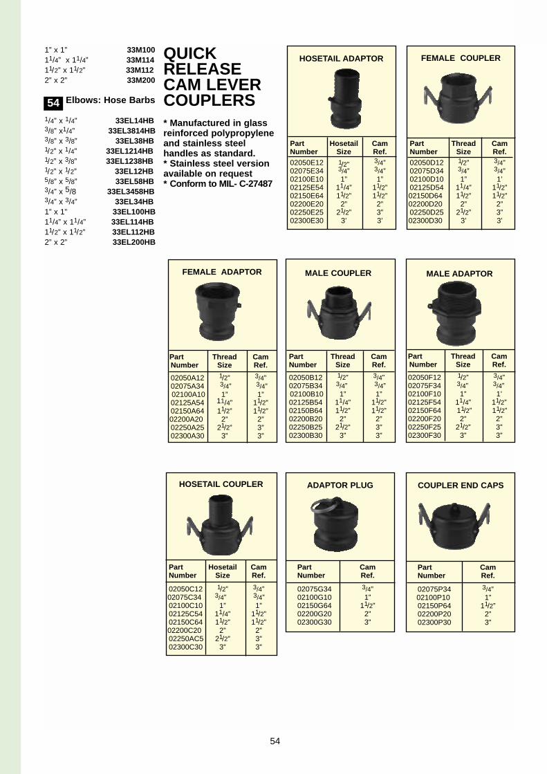
1” x 1” 33M10011/4” x 11/4” 33M11411/2” x 11/2” 33M1122” x 2” 33M200
Elbows: Hose Barbs
1/4” x 1/4” 33EL14HB3/8” x1/4” 33EL3814HB3/8” x 3/8” 33EL38HB1/2” x 1/4” 33EL1214HB1/2” x 3/8” 33EL1238HB1/2” x 1/2” 33EL12HB5/8” x 5/8” 33EL58HB3/4” x 5/8 33EL3458HB3/4” x 3/4” 33EL34HB1” x 1” 33EL100HB11/4” x 11/4” 33EL114HB11/2” x 11/2” 33EL112HB2” x 2” 33EL200HB
QUICKRELEASECAM LEVERCOUPLERS* Manufactured in glassreinforced polypropyleneand stainless steel handles as standard.* Stainless steel versionavailable on request* Conform to MIL- C-27487
54
Part Thread CamNumber Size Ref.
02050A12 1/2” 3/4”02075A34 3/4” 3/4”02100A10 1” 1”02125A54 11/4” 11/2”02150A64 11/2” 11/2”02200A20 2” 2”02250A25 21/2” 3”02300A30 3” 3”
Part Hosetail CamNumber Size Ref.
02050C12 1/2” 3/4”02075C34 3/4” 3/4”02100C10 1” 1”02125C54 11/4” 11/2”02150C64 11/2” 11/2”02200C20 2” 2”02250AC5 21/2” 3”02300C30 3” 3”
Part Hosetail CamNumber Size Ref.02050E12 1/2” 3/4”02075E34 3/4” 3/4”02100E10 1” 1”02125E54 11/4” 11/2”02150E64 11/2” 11/2”02200E20 2” 2”02250E25 21/2” 3”02300E30 3’ 3’
Part CamNumber Ref.
02075G34 3/4”02100G10 1”02150G64 11/2”02200G20 2”02300G30 3”
Part Thread CamNumber Size Ref.
02050B12 1/2” 3/4”02075B34 3/4” 3/4”02100B10 1” 1”02125B54 11/4” 11/2”02150B64 11/2” 11/2”02200B20 2” 2”02250B25 21/2” 3”02300B30 3” 3”
Part Thread CamNumber Size Ref.02050D12 1/2” 3/4”02075D34 3/4” 3/4”02100D10 1” 1’02125D54 11/4” 11/2”02150D64 11/2” 11/2”02200D20 2” 2”02250D25 21/2” 3”02300D30 3’ 3’
Part Thread CamNumber Size Ref.
02050F12 1/2” 3/4”02075F34 3/4” 3/4”02100F10 1” 1’02125F54 11/4” 11/2”02150F64 11/2” 11/2”02200F20 2” 2”02250F25 21/2” 3”02300F30 3” 3”
Part CamNumber Ref.
02075P34 3/4”02100P10 1”02150P64 11/2”02200P20 2”02300P30 3”
HOSETAIL COUPLER
MALE COUPLER
COUPLER END CAPS
FEMALE ADAPTOR
FEMALE COUPLERHOSETAIL ADAPTOR
ADAPTOR PLUG
MALE ADAPTOR
54

VALVES ANDCONTROLSLurmark’s range of valvesand controls are suitablefor a wide range of industri-al applications.Manufactured in glass rein-forced polypropylene,stainless steel and brass,our range of ball valves aremanual or electric with ‘fullbore’ to minimise flowrestricion and pressureloss. In addition Lurmarkcan also offer a full rangeof solenoid valves, bib tapsand control panels. Pleasecontact our sales office foradditional information.
EconomySeriesManual BallValvesAll glass filled polypropylenefull bore 2 and 3 way ballvalves, 1/2” to 2” BSP femaleports
T H R E A D E D PART NOsCONNECTION 2-Way 3-Way
1/2” BSP(F) 5 4 C A 2 0 0 05 4 C A 3 0 0 0
3/4” BSP(F) 5 4 C A 2 0 0 15 4 C A 3 0 0 1
1” BSP(F) 5 4 C A 2 0 0 25 4 C A 3 0 0 2
11/4” BSP(F) 5 4 C A 2 0 0 35 4 C A 3 0 0 3
Threaded Part Nos
Connection 2-
Way 3-Way
1/2” BSP(F) 56454132 56454233/4” BSP(F) 56454133 564542331” BSP(F) 56454134 56454234 11/4” BSP(F) 56454135 56454235
Electrically Operated Ball Valves
55
• 12v DC electrically actuatedball valves with other voltagesavailable on request• Main bodies for 11/4” & 2”
models as manual valves. • 1/2” , 3/4” , 1” & 11/4” in
compact design• Optional st/steel balls for
1/2” 3/4” 1” & 11/4” sizes.• Glass filled polypropylene

PRESSUREGAUGESLurmark offer a wide rangeof pressure gauges, idealfor a variety of industrialapplications.Casings are in ABS, metaland stainless steel. Gauges made of stainlesssteel throughout are alsoavailable.Unfilled (dry) and glycerinefilled and in sizes 2 1/2”(63mm) and 4” (100mm)are available as standard ingraduations from 0.2 bar(360 psi) up to 640 bar(10,000 psi).Bottom, dual scaled andrear entry versions andmounting brackets for backconnections are available.Contact Lurmark for detailsof the range of gaugeisolators.
ABS Cased* Case: 21/2” diameter ABS.* Connection: 1/4” BSP
brass parallel thread, bottom connection.
* Scale: Dual bar and psi (Except vacuum version).
* Dry and bidistilledglycerine filled.
Ideal for use with fluidswith relatively low viscosity.
DRY0-30 PSI (2 bar) 360-030S0-60 PSI (4 bar) 360-060S0-100 PSI (7 bar) 360-100S0-160 PSI (11 bar) 360-160S0-200 PSI (14 bar) 360-200S0-300 PSI (21 bar) 360-300S0-400 PSI (28 bar) 360-400S0-600 PSI (41 bar) 360-600S0-1000 PSI (70 bar) 360-1000S
GLYCERINE FILLED
0-30 PSI (2 bar) 3600310G0-60 PSI (4 bar) 3600410G0-100 PSI (7 bar) 360-100G0-160 PSI (11 bar) 3601010G
Glycerine filled C/W 1/4”BSP parallel threadedback connection
0-30 PSI (2 bar) 36EB-030G
0-60 PSI (4 bar) 36EB-060G
0-100 PSI (7 bar) 36EB-100G
0-160 PSI (11 bar) 36EB-160G0-200 PSI (14 bar) 36EB-200G0-300 PSI (21 bar) 36EB-300G0-400 PSI (28 bar) 36EB-400G0-600 PSI (41 bar)
36EB-600G
GLYCERINE FILLEDVACUUM30 PSI (2 bar) Vacuum
36VGG303060 PSI (4 bar) Vacuum
36VGG3060160 PSI ( 11 bar) Vacuum
36VGG30160
Metal Cased* Case: 4” diameter pressed
steel.* Connection: 3/8” BSP
brass parallel thread, bottom connection.
* Scale: Dual bar and psi Suitable for fluids ofrelatively low viscosity.
DRY
0-100 PSI (7 bar) 364-100S0-160 PSI (11 bar) 364-160S
Stainless SteelCased* Case: 21/2” diameter
stainless steel 304.* Connection: 1/4” BSP
brass parallel thread, bottom connection.
* Scale: Dual bar and psi * Dry and bidistilled
glycerine filled.Ideal for use with fluidswith relatively low viscosity.
DRY
0-30 PSI (2 bar) 36EB030S 0-60 PSI (4 bar) 36EB060S0-100 PSI (7 bar) 36EB100S
Glycerine filled - Bottom Entry
0-30 PSI (2 bar) 360-030G0-60 PSI (4 bar) 360-060G0-100 PSI (7 bar) 360920100-160 PSI (11 bar) 360-160G0-200 PSI (14 bar) 360-200G0-300 PSI (21 bar) 360-300G0-400 PSI (28 bar) 360-400G0-600 PSI (41 bar) 360-600G0-1000 PSI (70 bar) 360-1000G0-1500 PSI (103 bar) 360-1500G0-2000 PSI (138 bar) 360-20000-3000 PSI (207 bar)
G360-3000G
0-4000 PSI (275 bar)360-4000G
0-10000 PSI (690 bar)360-10000G
Glycerine filled - Back Entry
0-30 PSI (2 bar) 36EB030G0-60 PSI (4 bar) 36EB060G0-100 PSI (7 bar) 36EB100G0-160 PSI (11 bar) 36EB160G0-200 PSI (14 bar) 36EB200G0-300 PSI (21 bar) 36EB300G0-400 PSI (28 bar) 36EB400G0-600 PSI (41 bar) 36EB600G0-1000 PSI (70 bar)
36EB1000G0-1500 PSI (103 bar)
36EB1500G0-2000 PSI (138 bar)
36EB2000G0-3000 PSI (207 bar)
36EB30000-4000 PSI (275 bar)
36EB4000G0-10000 PSI (690 bar)
36EB10000G
All Stainless Steel * Case: 21/2” or 4” diameter
stainless steel 304.* Connection: 1/4” and 1/2”
stainless steel.* Scale: Dual bar and psi * Dry and bidistilled
glycerine filled.Ideal for use withaggressive fluids or inagressive environments.
DRY
0-25 PSI (1.7 bar)360-025GSS
0-100 PSI (7 bar)360-100GSS
0-250 PSI (17 bar)360-250GSS
GLYCERINE FILLED
0-25 PSI (1.7 bar) 364S025G0-100 PSI (7 bar) 364S100G0-250 PSI (17 bar) 364S250G
56

The F2 SeriesApplications:General plant careCleaning productsCar shampoosDisinfectants
With a 1.5Lt working capacity,the F2 Series are ideal fortargeting treatments in smallareas. Complete with anadjustable nozzle andon-off trigger, these hand-powered sprayers offer pre-cise flow control. Viton sealsare provided as standard onthe Laser 2 version, makingthis sprayer ideal for use withdisinfectants and cleaningproducts.
The Elyte MFSeriesApplications:Wood preservativesPest controlDisinfectantsAcid-based cleaning products
Available with 5 or 8 litre tankcapacity, the Elyte MF seriesare ideal for treating areas ofmore than 800 squaremetres. With viton sealsfitted as standard, this seriesof compression sprayers issuitable for use with aggres-sive chemicals such as woodpreservatives. The manysafety features include a tankwith a wide opening for easyfilling, the separately fixedside mounted pump that doesnot need to be removed onfilling and a pressure reliefvalve set at 3 bar.
The Laser G8and G10Applications:Acid-based productsSurface water proofingAlkaline productsForm removing oils
Complete with polypropylenetank, pump, flexible rein-forced hose and viton sealsas standard, the G8 and G10sprayers are suitable for usewith more aggressive chemi-cals such as acid-based prod-ucts. In addition, thesesprayers have a translucenttank for ease of filling andadjustable nozzle for accuratetargeting of chemicals.
PEDESTRIANSPRAYERSLurmark's range ofrobust sprayers meet allthe needs of the professional user.Every sprayer, from the1.5 litre hand-held pressure sprayer to the120 litre wheelbarrow isprecision-engineered togive long and troublefree service. A selectionof the models Lurmarkcan provide are shownbelow. Should yourequire information onthe complete range thenplease contact our technical experts.
Model Seals Capacity Dry Wt. Part No. Litres kg
F2 PLUS EPDM 1.5 0.75 19101223
LASER 2 Viton 1.5 0.47 19101321
ELYTE 7 MF Viton 5 1.5 18101352
ELYTE 13 MF Viton 8 2 18101354
G8 Viton 5 1.94 188808G10 Viton 8 2.1 188810
VERMOREL2000 PRO HP EPDM 16 5.5 18102028
LASER 2000 MF Viton 16 5 18102025
VERMOREL2000 PRO EP EPDM 18 8.3 19102040
DISINFECTIONUNIT Viton 120 58 1802520
57

Vermorel2000 ProSeriesApplications:Weed and insect controlTimber treatmentDisinfectant applicationWaterproofing
A combination of advancedtechnology and operator com-fort makes Vermorel 2000knapsacks ideal sprayers forthe professional user. Thehigh capacity membrane andcurvilinear pump enablesquick and efficient pumping ofthe liquid, which is deliveredto the nozzle on demand fromthe new profile trigger. Inaddition, operators experi-ence a high level of comfortdue to the ergonomic back-pack frame and paddedshoulders and waist straps.Models complete with Vitonseals (Laser 2000) or a fullyelectrically operated, com-plete with charger (Vermorel2000 EP) are available fromstock.
DisinfectionUnits
With a tank capacity of 120L, the Disinfection unit is suit-able for treating animal hous-es and breading sheds. Theunit has a maximum flowrate and pressure of 6 L/minand 10 bar, respectively.
Constructed of polyethylenewith a galvanised steel chas-sis, the unit comes completewith a giant telescopic lancewhich can extend to 2.4 m. Petrol and electric drive avail-able.
58


`Making spraying more efficient worldwide