Embed Size (px)
Citation preview
Doc. No: TM-638019700 Release Date: 02-21-12 UNCONTROLLED COPY Page 1 of 13
Revision: A Revision Date: 02-21-12
Hand Held Pull Tester Instruction Manual
Order No. 63801-9700

Hand Held Pull Tester
Doc. No: TM-638019700 Release Date: 02-21-12 UNCONTROLLED COPY Page 2 of 13
Revision: A Revision Date: 02-21-12
Safety Warnings and Information
Read and understand all of the instructions and safety information in this manual before operating or servicing this tool.
Keep this manual available when using this tool.
Replacement manuals are available for download at no charge at www.molex.com.
SAFETY ALERT SYMBOL This symbol is used to call your attention to hazards or unsafe practices which could result in an injury or property damage. The signal word, defined below, indicates the severity of the hazard. The message after the signal word provides information for preventing or avoiding the hazard.
DANGER
DANGER: Indicates an imminently hazardous situation which, if not avoided, could result in death or serious injury.
WARNING
WARNING: Indicates a potentially hazardous situation which, if not avoided, could result in death or serious injury.
CAUTION
CAUTION: Indicates a potentially hazardous situation which, if not avoided, may result in minor or moderate injury.
CAUTION may also be used to alert against unsafe practices associated with events that could lead
to personal injury.
WARNING WARNING
Always wear proper eye protection when Operating or servicing this tool. Failure to wear eye protection could result in serious eye injury from flying debris during test.
Never install or service this tool while connected to any electrical power source. Disconnect power by unplugging the tool from its power source. Failure to observe this warning could result In severe injury or death.
WARNING
WARNING
Never operate, service, install, or adjust this Machine without proper instruction and without first reading and understanding the instructions in this manual and all applicable press and/or wire processing machine manuals.
Do not use compressed air to clean the equipment. The forces created by compressed air can force debris into the tool. Failure to observe these precautions may result in injury or property damage.
WARNING
WARNING
Never use this machine without safety devices that are intended to prevent hands from remaining in the tool. Failure to observe this warning could result in severe injury or death.
Do not expose this equipment to moisture. To prevent fire and shock hazard, Always unplug the AC line cord prior to servicing. Failure to observe this warning could result In severe injury or death.
Hand Held Pull Tester
Doc. No: TM-638019700 Release Date: 02-21-12 UNCONTROLLED COPY Page 3 of 13
Revision: A Revision Date: 02-21-12
WARNING
Do not exceed the rated force capacity 200 lbs / 90.7 kg / 889.6 N. The unit may be damaged, and the operator or others in the immediate vicinity injured under extreme force conditions. Do not remove the warranty seal or disassemble the display module. Disassembly will void the warranty.
CAUTION
Never perform any service or maintenance other than as described in this manual. Never modify, alter or misuse the equipment Failure to observe this precaution may result in injury and / or property damage.
Tooling Technical Assistance Molex offers tooling technical assistance for customers who may need some guidance for tooling adjustments. This support can be obtained by calling either of the two numbers listed below and asking for the Molex Tooling Group. Call Toll Free 1-800-786-6539 (US) 1-630-969-4550 (Global). This assistance is limited to the operation and set-up of a customer’s Molex tool. Questions with regard to Molex connector products or how to identify the proper tooling and/ or tooling documentation should be directed to your local Molex personnel or Customer Service Representative. When calling for service on the hand held pull tester it is recommended to have the following: a copy of the Tooling Manual and a person familiar with the pull tester should be present. The following information is also recommended to supply:
1. Customer name 2. Customer address 3. Person to contact such as (name, title, e-mail, and telephone number) 4. Hand held pull tester number (638019700) 5. Urgency of request 6. Nature of problem
Molex Application Tooling Group 2200 Wellington Court Lisle, IL 60532, USA
Tel: +1 (630) 969-4550 Fax:+1 (630) 505-0049
Visit our Web site at http://www.molex.com
Hand Held Pull Tester
Doc. No: TM-638019700 Release Date: 02-21-12 UNCONTROLLED COPY Page 4 of 13
Revision: A Revision Date: 02-21-12
Table of Contents
Contents Hand Held Pull Tester............................................................................................................................................................................ 1
Safety Warnings and Information ............................................................................................................................................................ 2
Tooling Technical Assistance .................................................................................................................................................................. 3
Table of Contents .................................................................................................................................................................................... 4
Section 1 .................................................................................................................................................................................................. 5
General Descrition .............................................................................................................................................................................. 5
1.1 Features ................................................................................................................................................................................. 5
1.2 Technical Specification .......................................................................................................................................................... 5
1.3 Description ............................................................................................................................................................................. 5
1.4 Delivery Check ....................................................................................................................................................................... 6
1.5 Tools ...................................................................................................................................................................................... 6
Section 2 .................................................................................................................................................................................................. 7
Set-up and Operation .......................................................................................................................................................................... 7
2.1 Principal Mechanical Parts of the Hand Held Pull Tester ....................................................................................................... 7
2.2 Set-Up .................................................................................................................................................................................... 8
2.3 Charging................................................................................................................................................................................. 8
2.4 Operation ............................................................................................................................................................................... 8
2.5 Functional (R-Cal) Check ..................................................................................................................................................... 10
2.6 Service ................................................................................................................................................................................. 11
Section 3 ................................................................................................................................................................................................ 12
Maintenance ...................................................................................................................................................................................... 12
3.1 Spare Parts .......................................................................................................................................................................... 12
3.2 Maintenance ......................................................................................................................................................................... 12
3.3 Warranty............................................................................................................................................................................... 12
Section 4 ................................................................................................................................................................................................ 13
Parts List and Assembly .................................................................................................................................................................... 13
4.1 Parts List .............................................................................................................................................................................. 13
4.2 Assembly.............................................................................................................................................................................. 13
Hand Held Pull Tester
Doc. No: TM-638019700 Release Date: 02-21-12 UNCONTROLLED COPY Page 5 of 13
Revision: A Revision Date: 02-21-12
Section 1
General Descrition
1.1 Features
���� Built-in NIMH (Nickel Metal Hydride) battery with charger included ���� 14 hours of use on a single charge ���� Portable, lightweight and ergonomic ���� Patented low stress tensioning mechanism ���� Protective carrying / storage case ���� Operator can verify calibration at anytime ���� Operator selects force display in either:
o Pounds (lbs) o Kilograms (kg) o Newtons (N)
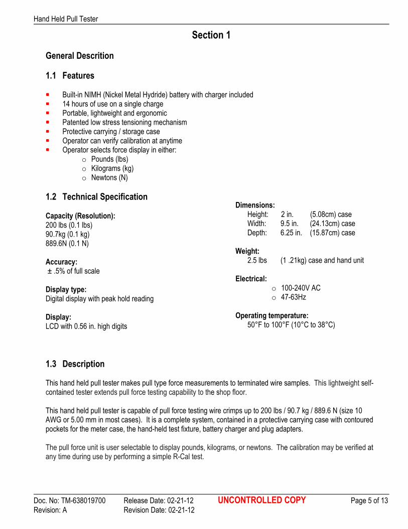
1.2 Technical Specification Capacity (Resolution): 200 lbs (0.1 lbs) 90.7kg (0.1 kg) 889.6N (0.1 N) Accuracy: ± .5% of full scale
Display type: Digital display with peak hold reading Display: LCD with 0.56 in. high digits
Dimensions:
Height: 2 in. (5.08cm) case Width: 9.5 in. (24.13cm) case Depth: 6.25 in. (15.87cm) case
Weight: 2.5 lbs (1 .21kg) case and hand unit
Electrical:
o 100-240V AC o 47-63Hz
Operating temperature:
50°F to 100°F (10°C to 38°C)
1.3 Description This hand held pull tester makes pull type force measurements to terminated wire samples. This lightweight self-contained tester extends pull force testing capability to the shop floor. This hand held pull tester is capable of pull force testing wire crimps up to 200 lbs / 90.7 kg / 889.6 N (size 10 AWG or 5.00 mm in most cases). It is a complete system, contained in a protective carrying case with contoured pockets for the meter case, the hand-held test fixture, battery charger and plug adapters. The pull force unit is user selectable to display pounds, kilograms, or newtons. The calibration may be verified at any time during use by performing a simple R-Cal test.
Hand Held Pull Tester
Doc. No: TM-638019700 Release Date: 02-21-12 UNCONTROLLED COPY Page 6 of 13
Revision: A Revision Date: 02-21-12
1.4 Delivery Check Carefully remove the tool from its shipping container and determine the following items are included in the package. Hand Held Pull Tester (Order No. 63801-9700) 1 Grip Assembly 1 Power Pack 1 Plug Adapters 4 TM-638019700 Operation Manual 1
1.5 Tools The following tools are recommended for setup and adjustments to the pull tester: 1. Standard 9/64 hex wrench 2. Standard 11/32 or adjustable wrench
Hand Held Pull Tester
Doc. No: TM-638019700 Release Date: 02-21-12 UNCONTROLLED COPY Page 7 of 13
Revision: A Revision Date: 02-21-12
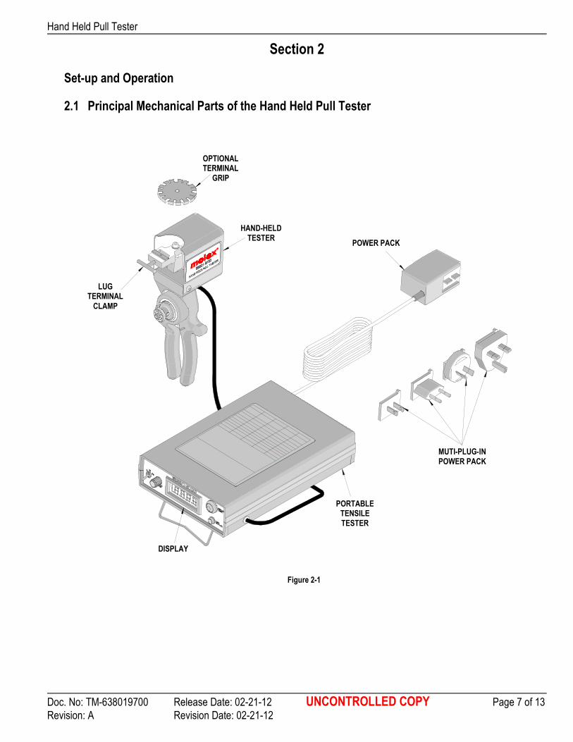
Figure 2-1
OPTIONAL TERMINAL
GRIP
HAND-HELD TESTER
LUG TERMINAL
CLAMP
DISPLAY
POWER PACK
MUTI-PLUG-IN POWER PACK
PORTABLE TENSILE TESTER
Section 2
Set-up and Operation
2.1 Principal Mechanical Parts of the Hand Held Pull Tester
Hand Held Pull Tester
Doc. No: TM-638019700 Release Date: 02-21-12 UNCONTROLLED COPY Page 8 of 13
Revision: A Revision Date: 02-21-12
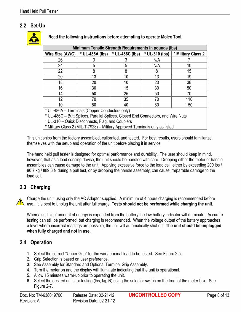
2.2 Set-Up
Read the following instructions before attempting to operate Molex Tool.
Minimum Tensile Strength Requirements in pounds (lbs)
Wire Size (AWG) * UL-486A (Ibs) * UL-486C (Ibs) * UL-310 (Ibs) * Military Class 2
26 3 3 N/A 7
24 5 5 N/A 10
22 8 8 8 15
20 13 10 13 19
18 20 10 20 38
16 30 15 30 50
14 50 25 50 70
12 70 35 70 110
10 80 40 80 150
* UL-486A – Terminals (Copper Conductors only) * UL-486C – Butt Splices, Parallel Splices, Closed End Connectors, and Wire Nuts * UL-310 – Quick Disconnects, Flag, and Couplers * Military Class 2 (MIL-T-7928) – Military Approved Terminals only as listed
This unit ships from the factory assembled, calibrated, and tested. For best results, users should familiarize themselves with the setup and operation of the unit before placing it in service. The hand held pull tester is designed for optimal performance and durability. The user should keep in mind, however, that as a load sensing device, the unit should be handled with care. Dropping either the meter or handle assemblies can cause damage to the unit. Applying excessive force to the load cell, either by exceeding 200 lbs / 90.7 kg / 889.6 N during a pull test, or by dropping the handle assembly, can cause irreparable damage to the load cell.
2.3 Charging Charge the unit, using only the AC Adaptor supplied. A minimum of 4 hours charging is recommended before use. It is best to unplug the unit after full charge. Tests should not be performed while charging the unit. When a sufficient amount of energy is expended from the battery the low battery indicator will illuminate. Accurate testing can still be performed, but charging is recommended. When the voltage output of the battery approaches a level where incorrect readings are possible, the unit will automatically shut off. The unit should be unplugged when fully charged and not in use.
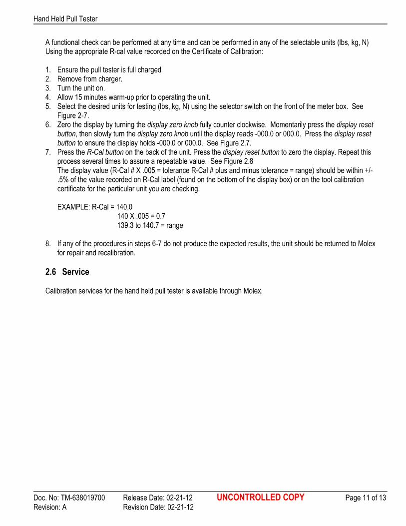
2.4 Operation 1. Select the correct "Upper Grip" for the wire/terminal lead to be tested. See Figure 2.5. 2. Grip Selection is based on user preference. 3. See Assembly for Standard and Optional Terminal Grip Assembly. 4. Turn the meter on and the display will illuminate indicating that the unit is operational. 5. Allow 15 minutes warm-up prior to operating the unit. 6. Select the desired units for testing (lbs, kg, N) using the selector switch on the front of the meter box. See
Figure 2-7.

Hand Held Pull Tester
Doc. No: TM-638019700 Release Date: 02-21-12 UNCONTROLLED COPY Page 9 of 13
Revision: A Revision Date: 02-21-12
7. Zero the display by turning the display zero knob fully counter clockwise. Momentarily press the display reset button, then slowly turn the display zero knob until the display reads -000.0 or 000.0. Press the display reset button to ensure the display holds -000.0 or 000.0. See Figure 2-7. Standard clamp (Figure 2-2) 1. Open Clamp enough for wire / terminal lead to fit in clamp. 2. Depress the cam shaft button, located on the center of the handles,
and insert the end of the wire sample in the hole located in the cam. See Figure 2-3.
3. Release the cam shaft button. 4. For best results, wrap the wire at least one full clockwise turn around the cam shaft. 5. Insert the wire / terminal lead in the terminal clamp, and tighten the grips T-handle to secure. Do not
clamp the conductor crimp. See Figure 2-4.
6. Begin to compress and release the handles slowly. 7. After the wire has separated from the termination, the tensile force required for the break can be read
directly from the meter display. 8. Remove the tested terminal from the terminal clamp assembly, and depress the button on the cam shaft
to remove the wire. Optional Grip (Figure 2-5) 1. Rotate the terminal grip and find the slot that is
the same width as the wire diameter, or one increment larger.
2. Depress the cam shaft button, located on the center of the handles, and insert the end of the wire sample in the hole located in the cam. See Figure 2-3.
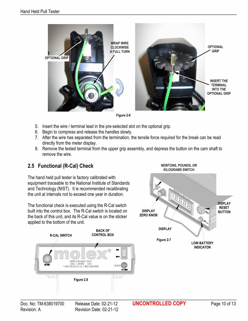
3. Release the cam shaft button. 4. For best results, wrap the wire at least one full clockwise turn around the cam shaft. See Figure 2-6.
STANDARD GRIP LUG TERMINAL CLAMP
Figure 2-2
OPTIONAL GRIP SLOT DIMENSION
Terminal Grip No. Size (in.) No. Size (in.)
Figure 2-5
1 .031 9 .094
2 .250 10 .188
3 .047 11 .110
4 .236 12 .172
5 .063 13 .125
6 .218 14 .158
7 .080 15 .141
8 .203
PUSH IN CAM SHAFT
BUTTON
WIRE
Figure 2-3 Figure 2-4
INSERT TERMINAL INTO THE
TERMINAL CLAMP
WRAP WIRE CLOCKWISE A FULL TURN
TERMINAL
CLAMP
Hand Held Pull Tester
Doc. No: TM-638019700 Release Date: 02-21-12 UNCONTROLLED COPY Page 10 of 13
Revision: A Revision Date: 02-21-12
DISPLAY ZERO KNOB
DISPLAY RESET
BUTTON
DISPLAY
Figure 2-7
NEWTONS, POUNDS, OR
KILOGRAMS SWITCH
LOW BATTERY INDICATOR
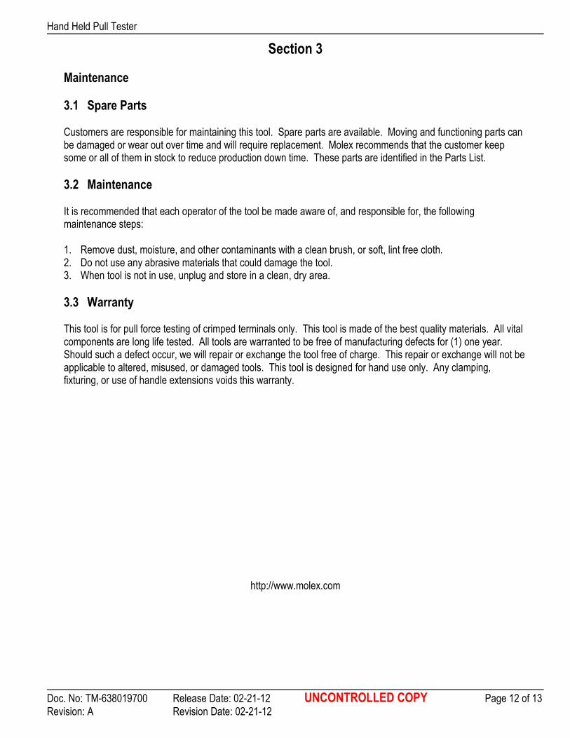
R-CAL SWITCH
Figure 2.8
BACK OF CONTROL BOX
5. Insert the wire / terminal lead in the pre-selected slot on the optional grip. 6. Begin to compress and release the handles slowly. 7. After the wire has separated from the termination, the tensile force required for the break can be read
directly from the meter display. 8. Remove the tested terminal from the upper grip assembly, and depress the button on the cam shaft to
remove the wire.
2.5 Functional (R-Cal) Check The hand held pull tester is factory calibrated with equipment traceable to the National Institute of Standards and Technology (NIST). It is recommended recalibrating the unit at intervals not to exceed one year in duration. The functional check is executed using the R-Cal switch built into the control box. The R-Cal switch is located on the back of this unit, and its R-Cal value is on the sticker applied to the bottom of the unit.
Figure 2-6
INSERT THE TERMINAL INTO THE
OPTIONAL GRIP
WRAP WIRE CLOCKWISE A FULL TURN
OPTIONAL GRIP
OPTIONAL
GRIP
Hand Held Pull Tester
Doc. No: TM-638019700 Release Date: 02-21-12 UNCONTROLLED COPY Page 11 of 13
Revision: A Revision Date: 02-21-12
A functional check can be performed at any time and can be performed in any of the selectable units (lbs, kg, N) Using the appropriate R-cal value recorded on the Certificate of Calibration: 1. Ensure the pull tester is full charged 2. Remove from charger. 3. Turn the unit on. 4. Allow 15 minutes warm-up prior to operating the unit. 5. Select the desired units for testing (lbs, kg, N) using the selector switch on the front of the meter box. See
Figure 2-7. 6. Zero the display by turning the display zero knob fully counter clockwise. Momentarily press the display reset
button, then slowly turn the display zero knob until the display reads -000.0 or 000.0. Press the display reset button to ensure the display holds -000.0 or 000.0. See Figure 2.7.
7. Press the R-Cal button on the back of the unit. Press the display reset button to zero the display. Repeat this process several times to assure a repeatable value. See Figure 2.8 The display value (R-Cal # X .005 = tolerance R-Cal # plus and minus tolerance = range) should be within +/-.5% of the value recorded on R-Cal label (found on the bottom of the display box) or on the tool calibration certificate for the particular unit you are checking.
EXAMPLE: R-Cal = 140.0
140 X .005 = 0.7 139.3 to 140.7 = range
8. If any of the procedures in steps 6-7 do not produce the expected results, the unit should be returned to Molex
for repair and recalibration.
2.6 Service Calibration services for the hand held pull tester is available through Molex.
Hand Held Pull Tester
Doc. No: TM-638019700 Release Date: 02-21-12 UNCONTROLLED COPY Page 12 of 13
Revision: A Revision Date: 02-21-12
Section 3
Maintenance
3.1 Spare Parts Customers are responsible for maintaining this tool. Spare parts are available. Moving and functioning parts can be damaged or wear out over time and will require replacement. Molex recommends that the customer keep some or all of them in stock to reduce production down time. These parts are identified in the Parts List.
3.2 Maintenance It is recommended that each operator of the tool be made aware of, and responsible for, the following maintenance steps: 1. Remove dust, moisture, and other contaminants with a clean brush, or soft, lint free cloth. 2. Do not use any abrasive materials that could damage the tool. 3. When tool is not in use, unplug and store in a clean, dry area.
3.3 Warranty This tool is for pull force testing of crimped terminals only. This tool is made of the best quality materials. All vital components are long life tested. All tools are warranted to be free of manufacturing defects for (1) one year. Should such a defect occur, we will repair or exchange the tool free of charge. This repair or exchange will not be applicable to altered, misused, or damaged tools. This tool is designed for hand use only. Any clamping, fixturing, or use of handle extensions voids this warranty.
http://www.molex.com

Hand Held Pull Tester
Doc. No: TM-638019700 Release Date: 02-21-12 UNCONTROLLED COPY Page 13 of 13
Revision: A Revision Date: 02-21-12
1
2
3
4
5
6
7
6
4
5
3
Section 4 Parts List and Assembly
4.1 Parts List
Hand Held Pull Tester 63801-9700
Item No. Order No. Eng No. Description Qty Notes
1 63801-9710 63801-9710 Lug Terminal Clamp Assembly 1
2 63801-9720 63801-9720 Terminal Grip Assembly 1
3 63801-9730 63801-9730 Power Pack 1
Hardware
4 NA NA #8-32 by 1 1/2” SHCS 2** Ref
5 NA NA #8-32 Lock Nut 2** Ref
6 NA NA #8-32 Washer 2** Ref
7 NA NA Spacer 1** Ref
** Available from an industrial supply company such as MSC (1-800-645-7270).
4.2 Assembly