Embed Size (px)
Citation preview

1
Hanbell Compressor Installation and Start-up Guide
RC2-100 to RC2-930
1. Compressor Crate Unpacking & Inspection
Inspect crate and compressor for any shipping damage. 1.1.
The compressor is in an easy open crate, cut straps and lift off crate top from base. 1.2.
Use either steel cable or safety ropes to lift the compressor, see Figure 1. The cable should be capable of holding 1.3.up to a minimum of 2 tons.
Figure 1 -Lifting Compressor with Steel Cable
Use caution while lifting the compressor
Make sure that the steel cable does not touch the Solenoid Valves, Capillary, Oil Heater, Discharge Temperature Sensor and or Power Terminals, etc. to prevent damage.
Use only steel cable or safety ropes to lift the compressor; make sure that the cable/rope has the proper strength to lift the compressor.
Keep the compressor horizontal while lifting.
Check compressor nameplate for correct model and voltage designation. 1.4.
To facilitate customer installation requirements, the parts listed in Table 1 are factory supplied in separate boxes 1.5.located in the compressor terminal box or packed in the compressor shipping container. Please verify that you have received all accessory parts.
Qty Description 1 Stop Valve Assembly
1 stop valve, 2 gaskets, 1 charging valve, 4 bolts, 1 half union connector, 1 flare nut, 1 flare seal bonnet
1 Discharge bushing connector 1 Suction bushing connector 1 Motor Terminal Junction Box Assembly
1 terminal box, 1 motor protection, 2 plastic terminal plugs, 1 reset button, 4 wires (refer to Figure 4-B)
Table 1: Compressor Accessories & Service Valve Parts

2
2. Compressor Safety Instructions
Follow recognized safety procedures and practices. 2.1.
In order to prevent the penetration of moisture, air or impurities, the compressor has been charged with Nitrogen 2.2.gas. Do not remove any compressor bolts or fittings until the factory supplied holding charge has been relieved!
Do not apply any power to the compressor unless all valves are open and solenoids are energized (suction / 2.3.discharge, service valves, economizer and oil shut off valves).
Do not operate or provide any electrical power to the compressor unless the terminal box cover is in place and 2.4.secured. Measurements of the current and voltage during running conditions must be taken at other points in the power supply.
Do not remove terminal box cover until all electrical sources have been disconnected. 2.5.
WARNING: Failure to follow these instructions could result in serious personal injury.
3. Installation Procedures
Holding Charge: The screw compressor is factory supplied with 7 psig (0.5 bar) holding charge of nitrogen gas. 3.1.The internal pressure must be relieved before attempting to remove any compressor fittings or parts. Relieve the holding charge by removing the threaded cap on the low pressure Schrader connection fitting and depressing the internal Schrader stem.
CAUTION: This compressor may contain trace amounts of oil. Do not relieve the holding charge or open the compressor pots until it is ready to be connected to a closed dry system. Excessive moisture may shorten compressor life.
Installation of the Compressor Electrical Terminal Box: Four bolts located on the top of the electrical terminal 3.2.box cover mount the electrical terminal box; it is adjustable to the cable hole direction to meet the power cables’ optional connection direction from the chiller.
Oils: Adding and removing oil is done through the Drain valve located on the solenoid side of compressor. The 3.3.compressor has no oil and is not charged with oil. When adding oil or doing a complete oil change, use only the listed Hanbell approved oils. POE oils readily absorb moisture and cause acid formation in the system. Keep oil exposure to the atmosphere to a minimum.
Installation of the Service/Stop Valve: Unpack the service/stop valve’s box then check against the list on the 3.4.outside of the box to ensure correct parts. Be sure that all parts inside the carton are clean. Use the four bolts to secure the service/stop valve. Use PTFE sealer to seal the adapter while tightening it. Please refer to Figure 5-A for space requirements for future service and maintenance needs.
Service/stop Valve Recommended Connection 3.5.
Figure 3-A RC2-100, 140 & 180
Figure 3-B RC2-170, 200~580 & 620
Figure 3-C RC2-610, 710~930

3
Liquid Injection Solenoid Valve and Expansion Valve (optional accessories): The liquid injection system may 3.6.be piped, but it is necessary to consider the required space for adjustment of the expansion valve while testing or running the compressor. Please refer to installation guide in the following section for connection points.
PTC Discharge Temperature Protection: Each compressor comes standard with three PTC sensors in the motor 3.7.windings and one located at the discharge port. A motor module (INT69HBY) is installed in the electrical terminal box. Refer to Figure 4-B showing the connection of motor and discharge PTCs in series to the motor module corresponding terminal blocks.
4. Recommended Liquid Injection Piping
Note A: It is necessary to adjust the Ball Valve to feed small amounts of liquid (drops) to the
compressor motor.

4
5. Screw Compressor Wiring Procedures
Following the diagrams below will prevent damage to the electrical terminals and the possibility of personal injury.

5
The method to tell the terminals:
1. By alphabet: Refer to the alphabet beside each terminal bolt in a star-delta motor.
2. By numbers: Refer to the number beside each bolt in a PWS motor.

6
Figure 5-A Motor Wiring

7
Across the Line Jumper Bar Installation
Install extra nuts under jumper bar for clearance of power bolt insulation

8
Figure 5-B Motor Protection Wiring
6. INT69HBY
The motor protector INT69HBY has been specially developed to monitor motor winding temperature, phase sequence and
phase failure on compressors.
1. When supply voltage is applied, the output relay pulls in after an initialization period of approx. 3 seconds, provided
all thermistors are below their rated response temperature.
2. There are 3 thermistors in the motor housing and 1 in the discharge neck, which are connected in series to the input
terminals.
3. If any thermistor resistance increases above trip level the relay drops out. This failure results in a lockout. (5 minutes
delay for 1st PTC failure, 60 minutes delay for 2nd failure, lockout for 3rd failure.)
4. If a rapid temperature increase is detected (locked rotor condition), the output relay drops out. This failure results in
a lockout.
5. The phase monitoring function is active 1 second after motor start during a 10 second window. Incorrect phase
sequence results in lockout trip. Phase loss results in lockout trip.
6. Lockout and time delay can be cancelled by mains reset of approx. 5 seconds.

9
7. To avoid nuisance tripping due to reverse
running after shutdown (pressure
equalization), the phase monitoring function is
only re-enabled approx. 20 seconds after
motor stop.
8. A twin LED (red / green) provides operational
information.
9. The relay is fed out as a N/O dry contact,
which is closed under good conditions.
10. Sensor and supply circuits are galvanic
isolated.
11. The motor protector is not suitable for use
with frequency converters.
INT69HBY Technical Data

10

11

12

13
7. Maintenance Area Requirement
Please refer to the below tables for recommended minimum space requirements
RC2-100 RC2-140 RC2-180 RC2-170 RC2-200 RC2-230 RC2-260 RC2-300 A.(cm) 5.9” (15) 16.1” (41) 18.1” (46) 18.5” (47) 20.1” (51) B.Outwards(cm) 11” (28) C.(cm) 9.8” (25) 10.2 (26) 11.8” (30) 13” (33) D.(cm) 5.9” (15) E.Suction filter(mm) 3.7” (95) 4” (103) 5.6” (143) F.Oil filter(mm) 7.8” (200) RC2-310 RC2-320 RC2-340 RC2-370 RC2-410 RC2-470 RC2-510 RC2-550 A.(cm) 20” (51) 22” (56) 21.3” (54) 23.3” (59) 21.7” (55) 23.3” (59) B.Outwards(cm) 11” (28) C.(cm) 13” (33) 11.8” (30) 13.8” (35) 14.6” (37) D.(cm) 5.9” (15) E.Suction filter(mm) 5.6” (143 6” (153) F.Oil filter(mm) 7.8” (200) RC2-580 RC2-610 RC2-620 RC2-710 RC2-790 RC2-830 RC2-930 A.(cm) 21.7” (55) 23.6” (60) 23.6” (60) 25.6” (65) 31.5” (80) B.Outwards(cm) 11” (28) 13.8” (35) 11” (28) 13.8” (35) C.(cm) 13.8” (35) 14.6” (37) 17.7” (45) D.(cm) 5.9” (15) --- 5.9” (15) --- E.Suction filter(mm) 6” (153) 8.2” (210) 6” (153) 8.2” (210) F.Oil filter(mm) 7.8” (200) 9.1” (232) 7.8” (200) 9.1” (232)

14
Table 7-A Compressor Recommended Space for Maintenance
Reserve enough space for connection and installation of the electrical terminal box, service/stop valves and 7.1.solenoid valves on the compressor.
Consider the compressors’ future overhaul when determining space requirements. All compressors’ outside parts 7.2.and electrical controller lines and terminal connections etc should be spaced for easy dismantle and re-assemble.
Recommended Maintenance Schedule
Note: This table is only to be used as a rough estimate, not a basis for any claim. The most appropriate running period for each
checkpoint is varied with operating condition (air-cooled or water-cooled), refrigerant, and lubricant (synthetic or mineral).
Replacement of piston rings and bearings should be performed by Hanbell authorized technicians. When counts of piston
loading and unloading motion are higher than 10,000 times, piston rings should be replaced immediately.
8. Compressor Piping
To avoid abnormal vibration and noise pay 8.1.close attention to how the compressor is piped.
The welding for the compressor should contain 8.2.at least 15% Argentina as an ingredient. Once all piping is completed, perform a pressure test to ensure there are no leaks (maximum compressor pressure 350 psi or 24 bar). The cleanliness of the system after pipe welding should help avoid any swarf or debris operating inside the system that can cause compressor damage during operation.
To avoid compressor harmonic vibration 8.3.transferred by the structure and piping to the chiller while in operation, a cushion or shock absorber should be installed on the suction and discharge tube.
Refer to Figure 6-A showing a 6mm to 15mm 8.4.
shock absorber installed under the compressor-mounting pad to isolate the vibration and noise transferred to other portions.
Figure 8-A Absorber Installation

15
In order to reduce vibration, copper tubes for 8.5.suction and discharge pipes are recommended; copper suction and discharge pipes will minimize the vibration from the piping while the compressor is running. In the case of steel piping, it is very important for suitable welding to avoid the inner stress on piping due to harmonic vibration and noise, which will reduce the compressor life.
Remove oxidized impurities, swarf or debris 8.6.caused by welding on piping tubes, if these impurities, swarf or debris are in the compressor, the oil filter will be clogged resulting in the lubrication system bearings and capacity control system malfunctioning.
The suction and discharge flanges are forged 8.7.steel that can be welded directly with piping connectors (standard size for copper piping, if connecting to steel piping contact your Hanbell representative) After welding the flanges and pipes, they should be cooled down by ambient air; water quenching is prohibited. Do not use water to cool down the pipes and flanges after welding.
9. Electrical Wiring
If the compressor application is low voltage, the following items should be considered:
Use conduit to insulate and protect the main 9.1.power cables between the control panel and compressors’ electrical terminal box.
Press each main power cable connecting head 9.2.with bolts firmly on each power terminal in electrical terminal box. Keep enough space and distance between the main power cable heads.
Choose suitable electrical accessories to meet 9.3.the required critical running conditions. An AC-3 contactor is recommended to meet the rated capacity of power. Select an overload protector with a response time of 15 seconds for overload.
Ensure the electricity voltage drop between 9.4.each two phases is less than 2%. If unable to reduce the length of main power cable then a larger diameter of main power cable should be chosen. Please refer to Figure 7-A shown below.
Main power cable section area
(mm2) 8 14 22 30 38 50 60 80 100 125 150 200
Maximum continuous
current (Amp) 55 80 100 125 145 175 200 230 270 310 360 425
Table 9-A Main Power Cable Size vs MCC
Maximum main power cable temperature is at 60°C. Maximum ambient temperature is at 35°C.
To avoid any danger or accidents due to the 9.5.shortage of electrical power, you are required to follow local Electrical Regulations for the grounding of the electrical terminal box, heater and compressor body etc.
The motor PTC and discharge PTC are 9.6.temperature sensors with a quick response in relation to the temperature approach to their setpoint. The thermisters must be connected in series to a controller (INT69HBY – Kriwan provided with the compressor) in the terminal box for protection of the compressor. An alarm for the motor protector is required to be embedded on the control panel as an indicator. Do not bypass/jump-out the INT69HBY to start and run the compressor.
Warning: Wrong direction of rotation will cause severe compressor damage. Do not start the compressor without first reviewing the Start-up section of this document.
16
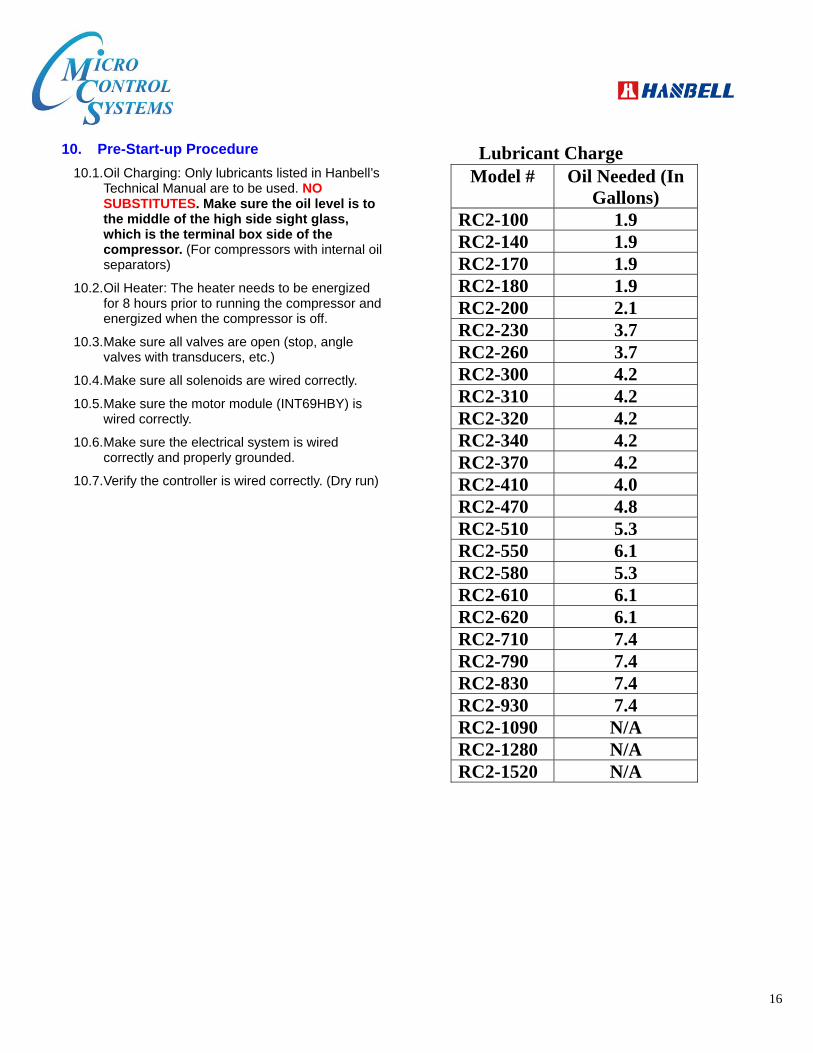
10. Pre-Start-up Procedure
Oil Charging: Only lubricants listed in Hanbell’s 10.1.Technical Manual are to be used. NO SUBSTITUTES. Make sure the oil level is to the middle of the high side sight glass, which is the terminal box side of the compressor. (For compressors with internal oil separators)
Oil Heater: The heater needs to be energized 10.2.for 8 hours prior to running the compressor and energized when the compressor is off.
Make sure all valves are open (stop, angle 10.3.valves with transducers, etc.)
Make sure all solenoids are wired correctly. 10.4.
Make sure the motor module (INT69HBY) is 10.5.wired correctly.
Make sure the electrical system is wired 10.6.correctly and properly grounded.
Verify the controller is wired correctly. (Dry run) 10.7.
Lubricant Charge Model # Oil Needed (In
Gallons) RC2-100 1.9 RC2-140 1.9 RC2-170 1.9 RC2-180 1.9 RC2-200 2.1 RC2-230 3.7 RC2-260 3.7 RC2-300 4.2 RC2-310 4.2 RC2-320 4.2 RC2-340 4.2 RC2-370 4.2 RC2-410 4.0 RC2-470 4.8 RC2-510 5.3 RC2-550 6.1 RC2-580 5.3 RC2-610 6.1 RC2-620 6.1 RC2-710 7.4 RC2-790 7.4 RC2-830 7.4 RC2-930 7.4 RC2-1090 N/A RC2-1280 N/A RC2-1520 N/A

17
Note: For other applicable oil types, please consult with HANBELL first for approval

18
NOTE: RC2-AF, RC2-BF, and LA Series Compressors do not have an Oil Separator or Sump These compressors do not hold oil and therefore have no oil filter, oil level switch, or heater. Therefore you must have an external oil separator with an oil sump and oil level float. Also, on the return line from the oil sump to the compressor you must have an oil filter and oil flow switch. Please follow the piping diagram below. Please ensure there is oil charged in the piping feeding the compressor to avoid a dry start-up.
In the lubricant circuit, installing the oil solenoid valve in the proper place is very important. As the compressor is shut down, lubricant will automatically inject into the compressor due to pressure differential. It will easily make the system difficult to restart because of low oil level or lubricant injection inside the compressor chamber.

19
11. Start-up Procedure
Check the rotation of the compressor by starting for 1 second. The correct rotating direction is suction pressure 11.1.drops and discharge pressure goes up. Proper rotation is critical. If the compressor is operated in reverse, severe damage may occur.
Recheck oil level. The oil level should be to the middle of the high side sight glass. 11.2.
Hanbell recommends suction superheat 10°F to 20°F, discharge superheat 30°F and a pressure differential of 11.3.at least 70 psig.
12. Recommended Safety Settings
a) Motor Module Trip (INT69HBY): Open for 1 second b) Low Oil Level Float Trip: Open for 30-60 seconds c) Unsafe Suction: Less than 5 psi for 3 seconds d) High Discharge Temperature: Greater than 215°F for 2 seconds e) Low Differential Pressure: Less than 65 psi for 60 seconds f) Unsafe Differential Pressure: Less than 35 psi for 5 seconds g) Dirty Filter (Discharge Pressure - Oil Pressure): Greater than 20 psi for 30 seconds h) Low Discharge Superheat: Less than 25°F for 300 seconds
13. Hanbell with VFD
Please follow these guidelines when installing a Variable Frequency Drive (VFD) on a Hanbell compressor:
Do not connect the INT69HBY 3 phase sensor (red/white/blue wires). 13.1.
Place the amp sensor(s) on the line side of the VFD. 13.2.
Select only a constant torque VFD type to use. 13.3.
Set for no Direct Current (DC) braking 13.4.
Set Acceleration Time to 3-5 second 13.5.
To setup a Hanbell RC2 series screw compressor to support a VFD:
1. Remove the 50% load solenoid coil (50% is no longer used).
2. The 25% load solenoid is used as the Fast Unload.
3. Remove the Load solenoid stem and install a Load Cap in its place.
4. Remove the red, white, and blue wires from the INT69HBY for the Phase Loss / Voltage safeties.

20
The final configuration should match the picture shown below:

21
Solenoid Identification

22
Infinite Capacity Minimum (50-100%)

23
Step Load 50%, 75%, 100%
Step Load 25%, 50%, 75%, 100% (Only 25% at
start-up and shut down)
See wiring diagram below

24
Solenoid Alignment
IMPORTANT: Solenoid alignment is critical to proper functioning of compressor When installing solenoids on compressor, ensure
that the holes match for proper oil flow to occur.
When installing Load Cap, make sure that the
circular indent covers both of the compressor oil
flow holes.

25
Also make sure holes line up if installing orifice
plate.
Proper installation of Solenoids With Orifice plate
Without Orifice plate

26
Not all oil flow holes are oriented the same way. Be sure to double check that the solenoid holes line up
properly as shown below.