Embed Size (px)
Citation preview
Hamiltonian design in readoutfrom room-temperature Raman atomic
memory
Michał Dabrowski, Radosław Chrapkiewicz,∗ and WojciechWasilewski
Institute of Experimental Physics, University of Warsaw, Pasteura 5, 02-093 Warsaw, Poland∗[email protected]
Abstract: We present an experimental demonstration of the Hamiltonianmanipulation in light-atom interface in Raman-type warm rubidium-87vapor atomic memory. By adjusting the detuning of the driving beam wevaried the relative contributions of the Stokes and anti-Stokes scatteringto the process of four-wave mixing which reads out a spatially multimodestate of atomic memory. We measured the temporal evolution of the readoutfields and the spatial intensity correlations between write-in and readout asa function of detuning with the use of an intensified camera. The correlationmaps enabled us to resolve between the anti-Stokes and the Stokes scat-tering and to quantify their contributions. Our experimental results agreequantitatively with a simple, plane-wave theoretical model we provide.They allow for a simple interpretation of the coaction of the anti-Stokes andthe Stokes scattering at the readout stage. The Stokes contribution yieldsadditional, adjustable gain at the readout stage, albeit with inevitable extranoise. Here we provide a simple and useful framework to trace it and theresults can be utilized in the existing atomic memories setups. Furthermore,the shown Hamiltonian manipulation offers a broad range of atom-lightinterfaces readily applicable in current and future quantum protocols withatomic ensembles.
© 2014 Optical Society of AmericaOCIS codes: (270.5585) Quantum information and processing; (020.0020) Atomic and molec-ular physics; (290.5910) Scattering, stimulated Raman; (190.4380) Nonlinear optics, four-wavemixing.
References and links1. A. I. Lvovsky, B. C. Sanders, and W. Tittel, “Optical quantum memory,” Nature Photon. 3, 706–714 (2009).2. L. M. Duan, M. D. Lukin, J. I. Cirac, and P. Zoller, “Long-distance quantum communication with atomic ensem-
bles and linear optics,” Nature (London) 414, 413–418 (2001).3. H. J. Kimble, “The quantum internet,” Nature (London) 453, 1023–30 (2008).4. J. Nunn, N. Langford, W. Kolthammer, T. Champion, M. Sprague, P. Michelberger, X. M. Jin, D. England, and
I. Walmsley, “Enhancing Multiphoton Rates with Quantum Memories,” Phys. Rev. Lett. 110, 133601 (2013).5. P. Kok, K. Nemoto, T. C. Ralph, J. P. Dowling, and G. J. Milburn, “Linear optical quantum computing with
photonic qubits,” Rev. Mod. Phys. 79, 135–174 (2007).6. A. Chiuri, C. Greganti, L. Mazzola, M. Paternostro, and P. Mataloni, “Linear optics simulation of quantum non-
Markovian dynamics,” Sci. Rep. 2, 968 (2012).7. A. Aspuru-Guzik and P. Walther, “Photonic quantum simulators,” Nature Phys. 8, 285–291 (2012).8. P. Neumann, R. Kolesov, B. Naydenov, J. Beck, F. Rempp, M. Steiner, V. Jacques, G. Balasubramanian, M. L.
Markham, D. J. Twitchen, S. Pezzagna, J. Meijer, J. Twamley, F. Jelezko, and J. Wrachtrup, “Quantum registerbased on coupled electron spins in a room-temperature solid,” Nature Phys. 6, 249–253 (2010).
#214300 - $15.00 USD Received 24 Jun 2014; revised 24 Aug 2014; accepted 19 Sep 2014; published 16 Oct 2014(C) 2014 OSA 20 October 2014 | Vol. 22, No. 21 | DOI:10.1364/OE.22.026076 | OPTICS EXPRESS 26076

9. P. C. Maurer, G. Kucsko, C. Latta, L. Jiang, N. Y. Yao, S. D. Bennett, F. Pastawski, D. Hunger, N. Chisholm,M. Markham, D. J. Twitchen, J. I. Cirac, and M. D. Lukin, “Room-temperature quantum bit memory exceedingone second,” Science 336, 1283–1286 (2012).
10. M. Hosseini, B. M. Sparkes, G. Campbell, P. K. Lam, and B. C. Buchler, “High efficiency coherent opticalmemory with warm rubidium vapour,” Nature Commun. 2, 174 (2011).
11. D. B. Higginbottom, B. M. Sparkes, M. Rancic, O. Pinel, M. Hosseini, P. K. Lam, and B. C. Buchler, “Spatial-mode storage in a gradient-echo memory,” Phys. Rev. A 86, 023801 (2012).
12. K. F. Reim, J. Nunn, V. O. Lorenz, B. J. Sussman, K. C. Lee, N. K. Langford, D. Jaksch, and I. A. Walmsley,“Towards high-speed optical quantum memories,” Nature Photon. 4, 218–221 (2010).
13. K. Reim, P. Michelberger, K. Lee, J. Nunn, N. Langford, and I. Walmsley, “Single-Photon-Level Quantum Mem-ory at Room Temperature,” Phys. Rev. Lett. 107, 053603 (2011).
14. S. E. Harris, “Electromagnetically Induced Transparency,” Physics Today 50(7), 36–42 (1997).15. M. Fleischhauer and M. D. Lukin, “Dark-state polaritons in electromagnetically induced transparency,” Phys.
Rev. Lett. 84, 5094–5097 (2000).16. M. D. Lukin and A. Imamoglu, “Controlling photons using electromagnetically induced transparency,” Nature
(London) 413, 273–276 (2001).17. M. Fleischhauer, A. Imamoglu, and J. Marangos, “Electromagnetically induced transparency: Optics in coherent
media,” Rev. Mod. Phys. 77, 633–673 (2005).18. M. Bashkansky, F. K. Fatemi, and I. Vurgaftman, “Quantum memory in warm rubidium vapor with buffer gas,”
Opt. Lett. 37, 142–144 (2012).19. R. Chrapkiewicz and W. Wasilewski, “Generation and delayed retrieval of spatially multimode Raman scattering
in warm rubidium vapours,” Opt. Express 20, 29540–29551 (2012).20. R. Chrapkiewicz, W. Wasilewski, and C. Radzewicz, “How to measure diffusional decoherence in multimode
rubidium vapor memories?,” Opt. Commun. 317, 1–6 (2014).21. K. Jensen, W. Wasilewski, H. Krauter, T. Fernholz, B. M. Nielsen, M. Owari, M. B. Plenio, a. Serafini, M. M.
Wolf, and E. S. Polzik, “Quantum memory for entangled continuous-variable states,” Nature Phys. 7, 13–16(2010).
22. P. K. Vudyasetu, R. M. Camacho, and J. C. Howell, “Storage and Retrieval of Multimode Transverse Images inHot Atomic Rubidium Vapor,” Phys. Rev. Lett. 100, 123903 (2008).
23. O. Firstenberg, M. Shuker, A. Ron, and N. Davidson, “Colloquium: Coherent diffusion of polaritons in atomicmedia,” Rev. Mod. Phys. 85, 941–960 (2013).
24. S. de Echaniz, M. Koschorreck, M. Napolitano, M. Kubasik, and M. Mitchell, “Hamiltonian design in atom-lightinteractions with rubidium ensembles: A quantum-information toolbox,” Phys. Rev. A 77, 032316 (2008).
25. P. S. Michelberger, T. F. M. Champion, M. R. Sprague, K. T. Kaczmarek, M. Barbieri, X. M. Jin, D. G. England,W. S. Kolthammer, D. J. Saunders, J. Nunn, and I. A. Walmsley, “Interfacing GHz-bandwidth heralded singlephotons with a room-temperature Raman quantum memory,” arXiv:1405.1470.
26. M. G. Raymer, “Quantum state entanglement and readout of collective atomic-ensemble modes and optical wavepackets by stimulated Raman scattering,” J. Mod. Opt. 51, 1739–1759 (2004).
27. W. Wasilewski and M. Raymer, “Pairwise entanglement and readout of atomic-ensemble and optical wave-packetmodes in traveling-wave Raman interactions,” Phys. Rev. A 73, 063816 (2006).
28. A. Gorshkov, A. André, M. Lukin, and A. S. Sørensen, “Photon storage in Λ-type optically dense atomic media.II. Free-space model,” Phys. Rev. A 76, 033805 (2007).
29. E. Zeuthen, A. Grodecka-Grad, and A. S. Sørensen, “Three-dimensional theory of quantum memories based onΛ-type atomic ensembles,” Phys. Rev. A 84, 043838 (2011).
30. W. Wasilewski, T. Fernholz, K. Jensen, L. S. Madsen, H. Krauter, C. Muschik, and E. S. Polzik, “Generation oftwo-mode squeezed and entangled light in a single temporal and spatial mode,” Opt. Express 17, 14444–14457(2009).
31. C. Vitelli, N. Spagnolo, L. Toffoli, F. Sciarrino, and F. De Martini, “Enhanced Resolution of Lossy Interferometryby Coherent Amplification of Single Photons,” Phys. Rev. Lett. 105, 113602 (2010).
32. S. Fossier, E. Diamanti, T. Debuisschert, R. Tualle-Brouri, and P. Grangier, “Improvement of continuous-variablequantum key distribution systems by using optical preamplifiers,” J. Phys. B 42, 114014 (2009).
33. J. Kołodynski, J. Chwedenczuk, and W. Wasilewski, “Eigenmode description of Raman scattering in atomicvapors in the presence of decoherence,” Phys. Rev. A 86, 013818 (2012).
34. H. Krauter, D. Salart, C. A. Muschik, J. M. Petersen, H. Shen, T. Fernholz, and E. S. Polzik, “Deterministicquantum teleportation between distant atomic objects,” Nature Phys. 9, 400–404 (2013).
35. M. G. Raymer and J. Mostowski, “Stimulated Raman scattering: Unified treatment of spontaneous initiation andspatial propagation,” Phys. Rev. A 24, 1980–1993 (1981).
36. A. Gorshkov, A. André, M. Lukin, and A. S. Sørensen, “Photon storage in Λ-type optically dense atomic media.I. Cavity model,” Phys. Rev. A 76, 033804 (2007).
37. V. Boyer, A. M. Marino, R. C. Pooser, and P. D. Lett, “Entangled images from four-wave mixing,” Science 321,544–547 (2008).
38. C. H. van der Wal, M. D. Eisaman, A. Andre, R. L. Walsworth, D. F. Phillips, A. S. Zibrov, and M. D. Lukin,
#214300 - $15.00 USD Received 24 Jun 2014; revised 24 Aug 2014; accepted 19 Sep 2014; published 16 Oct 2014(C) 2014 OSA 20 October 2014 | Vol. 22, No. 21 | DOI:10.1364/OE.22.026076 | OPTICS EXPRESS 26077
“Atomic Memory for Correlated Photon States,” Science 301, 196–200 (2003).39. D. J. McCarron, I. G. Hughes, P. Tierney, and S. L. Cornish, “A heated vapor cell unit for dichroic atomic vapor
laser lock in atomic rubidium,” Rev. Sci. Instrum. 78, 093106 (2007).40. R. Chrapkiewicz, W. Wasilewski, and K. Banaszek, “High-fidelity spatially resolved multiphoton counting for
quantum imaging applications,” Opt. Lett. 39, 5090-5093 (2014).41. R. Chrapkiewicz, “Photon counts statistics of squeezed and multimode thermal states of light on multiplexed
on–off detectors,” J. Opt. Soc. Am. B 31, B8-B13 (2014).42. P. A. Moreau, F. Devaux, and E. Lantz, “The Einstein-Podolsky-Rosen paradox in twin images,”
arXiv:1404.3028.43. M. Shuker, O. Firstenberg, R. Pugatch, A. Ron, and N. Davidson, “Storing Images in Warm Atomic Vapor,”
Phys. Rev. Lett. 100, 223601 (2008).44. I. Vurgaftman and M. Bashkansky, “Suppressing four-wave mixing in warm-atomic-vapor quantum memory,”
Phys. Rev. A 87, 063836 (2013).
1. Introduction
On-demand retrieval of pre-stored photons can be accomplished using quantum memories [1].This is an indispensable technique for long distance quantum communication networks [2, 3]and for the enhanced generation of multi-photon states [4]. Such states find applications in alinear quantum computing scheme [5] or quantum simulators using linear optics [6, 7].
Implementations of quantum memories in room-temperature setups are among the mostauspicious in terms of possible future applications due to their robustness. Until now room-temperature quantum memories have been realized in solid state systems [8, 9] and in warmatomic ensembles [1] such as gradient echo memory [10, 11], Raman memory [12, 13] or EITmemory [14–17].
In this paper we focus on Raman-type atomic memory implemented in warm rubidium-87vapors [18–20]. In such memory photons are stored in atomic collective excitations called spin-waves. They are interfaced to photons via off-resonant Raman transitions. Storage times up to30 ms in a single spin-wave mode was demonstrated [21]. Multimode storage, both temporal[10] and spatial [11, 19], is also feasible. With the use of multiple transverse spin-wave modesimages can be stored and retrieved [22, 23]. The storage time of the multimode memory islimited by diffusional decoherence and thus can be prolonged by increasing the beam size[20, 23] at the expense of laser intensity.
Here we demonstrate experimentally the theoretical concept of “Hamiltonian design” pro-posed in [24]. We implement the Hamiltonian design at the readout from Raman atomic mem-ory. Ideal readout from Raman atomic memory relies on a pure anti-Stokes scattering processwhich maps the spin-wave state onto photons state. In real systems additional Stokes scatteringat the readout is virtually inevitable and it is a source of extra noise [13, 25]. By modifyingthe interaction Hamiltonian we are able to control the relative contributions of anti-Stokes andStokes scattering processes. In the particular setting of our experiment this enables parametricamplification of the readout, albeit with extra noise.
In this paper we use simple theoretical model describing the coaction between anti-Stokesand Stokes scattering in readout. Previous approaches to describe theoretically the readout ofspin-wave excitations in Raman scattering were focused only on pure anti-Stokes process. The-oretical descriptions of readout from Raman-type memory have already been given for a num-ber of cases, including spatio-temporal evolution with losses [26], temporal eigen-modes [27],optimized retrieval [28], and spatial modes [29]. However, in those papers emphasis was puton the pure anti-Stokes scattering. In the present paper we use the extended description of thereadout process [30], taking into account the four-wave mixing that includes the Stokes scatte-ring.
In the experiment we detect scattered light with spatial resolution and temporal gating. Thisenables directly relating the experimental results to the theoretical predictions for temporal
#214300 - $15.00 USD Received 24 Jun 2014; revised 24 Aug 2014; accepted 19 Sep 2014; published 16 Oct 2014(C) 2014 OSA 20 October 2014 | Vol. 22, No. 21 | DOI:10.1364/OE.22.026076 | OPTICS EXPRESS 26078
evolution of scattered light. Stokes and anti-Stokes light contributions can be distinguishedthrough intensity correlation measurements and quantified via careful post-processing.
We provide evidence for a possibility of engineering a wide range of atom-light interfaceswhich can be described theoretically as simultaneous readout and parametric amplification.This may enable enriching purely optical quantum metrology [31] or communication [32]schemes with quantum storage capabilities.
This paper is organized as follows: In Sec. 2 we introduce a single-mode, theoretical model oftemporal evolution of Stokes and anti-Stokes in readout, Sec. 3 describe experimental details, inSec. 4 we present the phenomenological model utilized for data analysis and the results; finallySec. 5 concludes the paper.
2. Theory
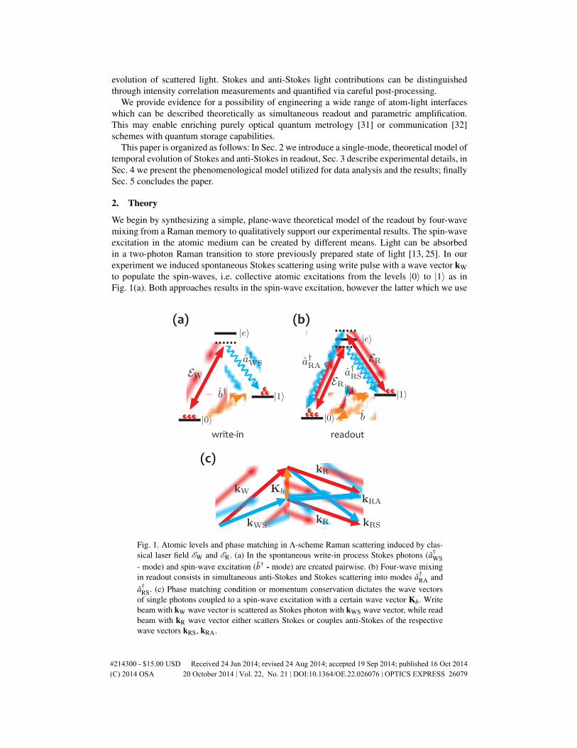
We begin by synthesizing a simple, plane-wave theoretical model of the readout by four-wavemixing from a Raman memory to qualitatively support our experimental results. The spin-waveexcitation in the atomic medium can be created by different means. Light can be absorbedin a two-photon Raman transition to store previously prepared state of light [13, 25]. In ourexperiment we induced spontaneous Stokes scattering using write pulse with a wave vector kWto populate the spin-waves, i.e. collective atomic excitations from the levels |0〉 to |1〉 as inFig. 1(a). Both approaches results in the spin-wave excitation, however the latter which we use
Pump
Write Read
EM CCDPBS PBS L
Rb cell87
(a)
(b)
Pump Write ReadDiffusion
0
(a)
(b)
Bit map
Pump Write ReadDiffusion
0
Pump
Write Read
EM CCDPBS PBS L
Rb cell87
(a) (c)
(b) (d)
Ew
EsEAS
ER
(a)
(b)
(a)
(b) (d)
Pump Write Read
Gate
time
Write Read
Delayed
time
gates
Pump
Write Read
I-sCMOSPBS PBS L
Rb cell87
(d)(a) (b)
(c)
(a) (b)
(c)
write-in readout
Fig. 1. Atomic levels and phase matching in Λ-scheme Raman scattering induced by clas-sical laser field EW and ER. (a) In the spontaneous write-in process Stokes photons (a†
WS- mode) and spin-wave excitation (b† - mode) are created pairwise. (b) Four-wave mixingin readout consists in simultaneous anti-Stokes and Stokes scattering into modes a†
RA anda†
RS. (c) Phase matching condition or momentum conservation dictates the wave vectorsof single photons coupled to a spin-wave excitation with a certain wave vector Kb. Writebeam with kW wave vector is scattered as Stokes photon with kWS wave vector, while readbeam with kR wave vector either scatters Stokes or couples anti-Stokes of the respectivewave vectors kRS, kRA.
#214300 - $15.00 USD Received 24 Jun 2014; revised 24 Aug 2014; accepted 19 Sep 2014; published 16 Oct 2014(C) 2014 OSA 20 October 2014 | Vol. 22, No. 21 | DOI:10.1364/OE.22.026076 | OPTICS EXPRESS 26079
does not require special efforts to match the photons from the external source to the memorybandwidth. Ideally, the number of created spin-wave excitations nb with a certain wave vectorKb equals the number of scattered Stokes photons with wave vector kWS = kW−Kb. We wereable to estimate those numbers in each single iteration of the experiment.
Here we focused on the retrieval stage at which the spin-wave excitations are converted tophotons in four-wave mixing induced by the read laser pulse depicted in Fig.1(b). The readlaser is assumed to be plane-wave with a wave vector kR. Spin-wave with a certain wave vectorKb are coupled to anti-Stokes and Stokes fields with wave vectors kRA = kR +Kb and kRS =kR−Kb respectively. In the experiment those weak light fields illuminated distinct pixels ofthe camera which was located in the far field. They were also shifted with respect to the initialStokes photons with the wave vector kWS = kW−Kb due to different direction of the writebeam kW. We summarize the phase matching condition relating the wave vectors in Fig. 1(c).
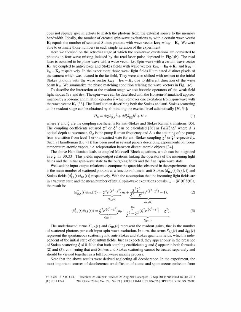
To describe the interaction at the readout stage we use bosonic operators of the weak fieldlight modes aRA and aRS. The spin-wave can be described with the Holstein-Primakhoff approx-imation by a bosonic annihilation operator b which removes one excitation from spin-wave withthe wave vector Kb [33]. The Hamiltonian describing both the Stokes and anti-Stokes scatteringat the readout stage can be obtained by eliminating the excited level adiabatically [30, 34]:
HR = ihχ a†RAb+ ihξ a†
RSb† +H.c. (1)
where χ and ξ are the coupling coefficients for anti-Stokes and Stokes Raman transitions [35].The coupling coefficients squared χ2 or ξ 2 can be calculated [36] as ΓdΩ2
p/∆2 where d isoptical depth at resonance, Ωp is the pump Raman frequency and ∆ is the detuning of the pumpfrom transition from level 1 or 0 to excited state for anti-Stokes coupling χ2 or ξ 2respectively.Such a Hamiltonian (Eq. (1)) has been used in several papers describing experiments on room-temperature atomic vapors, i.e. teleportation between distant atomic objects [34].
The above Hamiltonian leads to coupled Maxwell-Bloch equations, which can be integratedas e.g. in [30,33]. This yields input-output relations linking the operators of the incoming lightfields and the initial spin-wave state to the outgoing fields and the final spin-wave state.
We used the input-output relations to compute the quantities observed in the experiments, thatis the mean number of scattered photons as a function of time in anti-Stokes 〈a†
RA(t)aRA(t)〉 andStokes fields 〈a†
RS(t)aRS(t)〉 respectively. With the assumption that the incoming light fields arein a vacuum state and the mean number of initial spin-wave excitations equals nb = 〈b†(0)b(0)〉,the result is:
〈a†RA(t)aRA(t)〉= χ
2et(ξ 2−χ2)︸ ︷︷ ︸GRA(t)
nb +χ2ξ 2
ξ 2−χ2 (et(ξ 2−χ2)−1)︸ ︷︷ ︸
SRA(t)
, (2)
〈a†RS(t)aRS(t)〉= ξ
2et(ξ 2−χ2)︸ ︷︷ ︸GRS(t)
nb +ξ 2
ξ 2−χ2 (ξ2et(ξ 2−χ2)−χ
2)︸ ︷︷ ︸SRS(t)
, (3)
The underbraced terms GRA(t) and GRS(t) represent the readout gains, that is the numberof scattered photons per each input spin-wave excitation. In turn, the terms SRA(t) and SRS(t)represent the spontaneous scattering into anti-Stokes and Stokes quantum fields, which is inde-pendent of the initial state of quantum fields. Just as expected, they appear only in the presenceof Stokes scattering ξ 6= 0. Note that both coupling coefficients χ and ξ appear in both formulas(2) and (3), confirming that anti-Stokes and Stokes scattering cannot be treated separately andshould be viewed together as a full four-wave mixing process.
Note that the above results were derived neglecting all decoherence. In the experiment, themost important sources of decoherence are diffusion of atoms and spontaneous emission from
#214300 - $15.00 USD Received 24 Jun 2014; revised 24 Aug 2014; accepted 19 Sep 2014; published 16 Oct 2014(C) 2014 OSA 20 October 2014 | Vol. 22, No. 21 | DOI:10.1364/OE.22.026076 | OPTICS EXPRESS 26080

the excited state in random direction. Both can be neglected provided the optical depth is largeand the duration of the interaction short.
Let us proceed to examining the evolution of scattered anti-Stokes and Stokes light in a fewtypical cases.
For ξ ' 0 there is virtually no Stokes scattering while the anti-Stokes scattering appearsinstantaneously and decays exponentially as depicted in Fig. 2(a). There is virtually no spon-taneous noise SRA ' 0 and the time integrated gain reaches unity GRA =
´GRAdt = 1. In the
ideally case of ξ = 0 this leads to the readout Hamiltonian of form HR ∼ a†RAb+H.c. which
represent purely anti-Stokes scattering process.In real systems Stokes interaction is typically unavoidable. The case where χ > ξ > 0 is
depicted in Fig. 2(b). Here the readout appears in both the anti-Stokes and Stokes fields withcomparable intensity and decays over time. Time-integrated gain may reach over unity Gi =´
Gidt > 1, yet with spontaneous noise that slowly builds up Si > 0, for i = RA, RS. This is thesetting utilized in [37].
A situation where Stokes interaction dominates, ξ > χ , is depicted in Fig. 2(c). In this casereadout goes predominantly to Stokes field with exponentially increasing gain. Yet, the noiseintensity virtually equals the gain Gi ' Si for both fields. In the limit of ξ χ we can put χ = 0which leads to the readout Hamiltonian HR ∼ a†
RSb† +H.c. consists only the contribution ofStokes scattering process.
It is instructive to integrate gains GRA(t) and GRS(t), and noises SRA(t) and SRS(t) over thetime of interaction and inspect them as functions of coupling coefficients. Coupling coefficientsχ and ξ are inversely proportional to the detuning of the read laser from the excited level
0.0 0.2 0.4 0.6 0.80.0
0.5
1.0
1.5
2.0
2.5
3.0
Δ
ξ=0.2,χ =0.8
(a) (b)
(c) (d)0 2 4 6 8 10
0.01
0.02
0.05
0.10
0.20
0.50ξ=0.55,χ =0.45ξ=0.99,χ =0.01
0 2 4 6 8 1010- 8
10- 6
10- 4
0.01
1
t t
0 2 4 6 8 10
0.01
0.1
1
10
100
tR
GRA - anti-Stokes gain GRS - Stokes gain
SRA - anti-Stokes noise SRS - Stokes noise
tim
e in
tegr
ated
gai
n/no
ise
gain/n
oise
gain/n
oise
gain/n
oise
Fig. 2. (a) to (c) - temporal evolution of gains Gi and spontaneous noises Si building up thelight fields. Data plotted for different values of coupling coefficients χ and ξ correspond todetuning parameters ∆R= 0.3, 0.6 and 0.8. (d) Integrated readout gains Gi and spontaneousnoises Si versus detuning ∆R.
#214300 - $15.00 USD Received 24 Jun 2014; revised 24 Aug 2014; accepted 19 Sep 2014; published 16 Oct 2014(C) 2014 OSA 20 October 2014 | Vol. 22, No. 21 | DOI:10.1364/OE.22.026076 | OPTICS EXPRESS 26081
∆R [33,35]. One coupling coefficient can be increased at the expense of the other by tuning thefrequency of the read laser when it is in between the |0〉 ↔ |e〉 and |1〉 ↔ |e〉 resonances as inFig. 1(b).
In Fig. 2 (d) we plot the time integrated gains Gi =´
Gidt and noises Si =´
Sidt as a functionof the detuning ∆R from |0〉 ↔ |e〉 transition in the units of ground state splitting. We assumedχ ∝ 1/∆R and ξ ∝ 1/(1−∆R). Different characters of anti-Stokes and Stokes interaction causesasymmetry of the plot in Fig. 2 (d). The integrated readout gain in the anti-Stokes dominationregime χ ξ remains equal to unity GRA = 1 and the noise is suppressed SRA 1 . These arethe conditions for perfect unamplified readout.
On the contrary, in the Stokes domination regime χ ξ the integrated gain GRS varies almostexponentially with the Stokes coupling ξ entailing elevated noise SRS. In this domain four-wave mixing enhances the anti-Stokes emission and GRA rises although the relative contributionGRA/GRS diminishes. Note that this is the regime we use to populate the spin-waves by inducingspontaneous Stokes scattering with write pulse.
Finally, let us consider a single realization of the four-wave mixing process. Assume that thenumber of initial spin-wave excitations nb has been measured by counting the Stokes photonsnWS scattered during prior write-in, ideally nWS = nb. In this particular iteration the number ofphotons in the anti-Stokes and the Stokes field equals
ni = Ginb + Si, i = RS, RA (4)
where Si is the noise treated here as an independent random variable. Si is the time integratedspontaneous scattering and its mean is calculated based on Eqs. (2), (3) 〈Si〉= Si. Later on werefer to the correlation of the number of anti-Stokes nRA or Stokes photons nRS with the initialspin-wave excitation nb. The above formula links the correlated part to the integrated readoutgain Gi and the uncorrelated noise to the integrated spontaneous contribution Si.
3. Experiment
We implemented Raman-type atomic memory in rubidium-87 vapors. We applied spontaneouswrite-in process into memory similarly as in previous works [18,38]. The spontaneous write-inprocess had been proven to efficiently create the spin-wave excitations, thus we could focuson the retrieval characteristics. Here we extended the setup and measurements schemes appliedand explained in detail in our previous papers [19, 20].
We used a 10 cm glass cell containing pure 87Rb isotope with krypton as a buffer gas underpressure of 1 torr. The cell was heated by bifilar windings to 90oC equivalent to the optical
read
read
Stokes
6,835GHz
′
′
anti-Stokes
write
Stokes
pump(D1-line,(795nm)
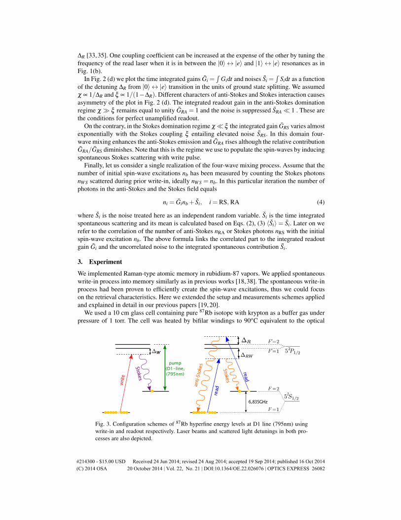
Fig. 3. Configuration schemes of 87Rb hyperfine energy levels at D1 line (795nm) usingwrite-in and readout respectively. Laser beams and scattered light detunings in both pro-cesses are also depicted.
#214300 - $15.00 USD Received 24 Jun 2014; revised 24 Aug 2014; accepted 19 Sep 2014; published 16 Oct 2014(C) 2014 OSA 20 October 2014 | Vol. 22, No. 21 | DOI:10.1364/OE.22.026076 | OPTICS EXPRESS 26082

density of 135. The cell was magnetically shielded to avoid decoherence produced by straymagnetic field and the main source of decoherence was due to diffusion [20].
We used three external cavity diode lasers: pump, write and read laser, operating at D1 line of87Rb (795 nm). The frequencies of all laser beams and the scattered light are sketched againstthe 87Rb level scheme in Fig. 3. The pump laser was resonant to F=2→F’=2 transition, whilethe write and read laser were detuned to the red from transition F=1→F=1’. The detuning of thewrite laser was ∆W = 1.77 GHz and it was kept constant throughout all measurements whilethe detuning of the read laser ∆R varied. The pump and write lasers were frequency lockedusing the DAVLL setup [39]. The exact values of the write and read lasers detunings wereset repeatedly and measured precisely using Doppler-free saturated absorption spectroscopyinside an auxiliary rubidium cell and their reference beat-note signal was measured on a fastphotodiode. Inside the cell write, read and pump lasers had the power of 6.8 mW, 4.5 mW and75 mW respectively. During the experimental sequence the lasers power fluctuated at a level of5% and the frequencies were changing by no more than 50MHz.
The simplified schematic of the setup is shown in Fig. 4(a). All of the three horizontallypolarized beams overlapped inside the cell where their diameters were 6 mm for the pumpbeam and 4 mm for both write and read beams. The write and read beams were tilted at theangle θ = 2 mrad. Acousto-optic modulators were used to shape rectangular pulses with risingtime of 1 µs from laser beams. The pulse sequence applied in the experiment is depicted inFig. 4(b). The sequence was initiated by optical pumping of rubidium atoms into the groundstate of 87Rb S1/2 F=1. The 700 µs long rectangular pulse of 75 mW power yielded a pumpingefficiency of 98%. Then we applied a 10 µs long rectangular write pulse to create spin-waveexcitations between F=1 and F=2 levels together with the Stokes scattering. The rectangularread pulse started right after the end of the write pulse and its duration was set to 40 µs. Theread pulse generated both anti-Stokes and Stokes scattering. The total time duration of write andread pulse corresponds to the average atomic displacement of c.a. 0.5 mm due to diffusion [20]which was small enough to keep the atoms in the range of the pump beam size.
We separated the horizontally polarized laser beams from the vertically polarized scattered
pump write read
WSRS+RA
read
intensifiergate
Pump
Write Read
Rb cell87
intensifiedcamera
85Rb filter
(a)
(b) (c)
RS+RA
Fig. 4. (a) Experimental setup: write and read laser beams propagate forward to the inten-sified camera and the pump beam propagates backward. 87Rb - atomic memory cell, 85Rb- absorption filter, blue arrows correspond to scattered light. (b) Pulse sequence with longintensifier gate covers the whole write and a part of the read pulse (both rectangular). Ex-ponential shapes in front of write and read pulses are typical time-resolved intensities ofthe scattered light observed on the intensified camera, WS and RS stand for Stokes whileRA for anti-Stokes scattering respectively. (c) Scheme of the measurement of the temporalevolution of the readout light using short gate duration τ = 250 ns.
#214300 - $15.00 USD Received 24 Jun 2014; revised 24 Aug 2014; accepted 19 Sep 2014; published 16 Oct 2014(C) 2014 OSA 20 October 2014 | Vol. 22, No. 21 | DOI:10.1364/OE.22.026076 | OPTICS EXPRESS 26083

(a)
−0.5 −0.25 0 0.25 0.5−2
−1.5
−1
−0.5
0
0.5
1
1.5
2
−0.5 −0.25 0 0.25 0.5
X (mrad)
Y (
mra
d)
(b)
X (mrad)
(c) (d)
X (mrad)0−0.35 0.35
X (mrad)0−0.35 0.35
Fig. 5. Representative images of the retrieved field, write-in and read-out in upper and lowerparts respectively. (a) Intensity map in a single shot obtained using a long gate in the linearregime of camera operation and (b) the average over 104 frames. (c) Photon positions in asingle shot [40] obtained using a short gate positioned in the readout stage and (d) the totalnumber of photons per sCMOS pixel summed over 2000 frames.
fields by polarization and spectral filtering, which yielded the total attenuation factor for laserbeams that exceeded 109. For spectral filtering we applied a 85Rb absorption filter at 130Cplaced in magnetic field which increase the absorption by broadening and shifting the 85Rbspectral lines. The attenuation of laser beams inside the 30 cm length absorption filter was atleast 104. We also measured the transmission of the filter at frequencies corresponding to thescattered light generated at write-in and readout stages. They were found to be 12% for Stokesscattering in write-in and 76% for all applied frequencies of anti-Stokes and Stokes in readout.
In our system we generated and retrieved spatially multimode light as described in detailin [19, 33]. This light was detected in the far field by a gated image intensifier coupled tosCMOS camera [40]. We used the intensified camera in two different operational schemes.In the first scheme we applied a long gate pulse which covered both the write and the readpulse as in Fig. 4(b). We set the gain of the intensifier to a low value. Then the response ofthe camera system was proportional to the intensity of scattered light. We calibrated the excessnoise contributed by the image intensifier and made sure that it was insignificant as compared tothe shot-to-shot intensity fluctuations of scattered light. In the second scheme we used a short,delayed gate of τ = 250 ns duration as depicted in Fig. 4(c). Here we set the image intensifierto high gain and the camera system was sensitive to single photons [40]. We also utilized anintensified camera as a photon number resolving detector [41] and we counted all photons witha quantum efficiency of 20% in the region of readout scattering. Representative images: singleshots and averaged intensities obtained typically in those regimes are depicted in Fig. 5. Notethat in Fig. 5(a) the number and localization of speckles are random so they average to thesmooth intensity profile as shown in Fig. 5(b). Both measurement regimes are phase insensitivealthough spatially resolved, homodyne-type detection was also reported [37] and then it couldbe used to directly measure phase noise and squeezing properties of the generated light.
4. Results
4.1. Temporal evolution of readout intensity
At first we measured the temporal evolution of the mean number of photons emitted duringreadout stage. For this purpose we counted the scattered photons using an intensified camerawith a gate duration of τ = 250 ns. We collected all photons in the specified circular cameraregion around the point corresponding to the center of the read beam i.e. wave vector kR. Thus,
#214300 - $15.00 USD Received 24 Jun 2014; revised 24 Aug 2014; accepted 19 Sep 2014; published 16 Oct 2014(C) 2014 OSA 20 October 2014 | Vol. 22, No. 21 | DOI:10.1364/OE.22.026076 | OPTICS EXPRESS 26084

0 5 10 15 20 25 30 35 400
10
20
30
40
50
gateRdelay δTRwithRrespectRtoRtheRreadRpulseRstartR6µs7nu
mbe
rRof
Rpho
tonR
coun
tsRp
erR2
50ns ∆
R=4.19GHz
∆R
=3.84GHz
∆R
=3.52GHz
∆R
=1.67GHz
Fig. 6. Average number of photon counts detected at a large solid angle around read beamper a gate duration of 250 ns for different readout laser detunings ∆R from 87Rb F=2 →F’=2 resonance. The curves represent exponential fits to the first and last data points. Thesize of errorbars is comparable with marker size.
we measured the anti-Stokes and the Stokes scattering together, both their spontaneous andstimulated parts. In Fig. 6 we present the results of measurement for mean number of photonsversus gate delay with exponential fits. Each data point was obtained by averaging 2000 framesin the area of angular diameter 0.5 mrad and the time separation between the data points was1 µs. The sequence was repeated for different detunings ∆R of the read beam from F=2→F’=2resonance.
The results plotted in Fig. 6 vividly depict a transition from decay to growth of the readoutscattered light intensity. For a small detuning ∆R = 1.67 GHz the read beam is close to theF=2→F’=2 resonance and we expected the anti-Stokes coupling to dominate. Indeed, we ob-served an exponential decay as predictied. At the opposite extreme ∆R = 4.19 GHz, in turn,the read beam is much closer to the F=1→F’=1 transition and here it was the Stokes field thatwe expected to dominate. Again, the total number of scattered photons increases as expected,compare Fig. 2(c). Nonetheless, in the experiment the growth starts after the first 4 µs of theevolution during which the number of scattered photons slightly decreases. In the intermediatecases we observed initial decay followed by growth. These cases might be associated with thecase presented in Fig. 2(b), where stimulated field contributions decay while the spontaneouscontributions rise. Moreover, in the observed evolution the spin-wave decoherence certainlyplays an important role, which, however, is not accounted for by our simplified model.
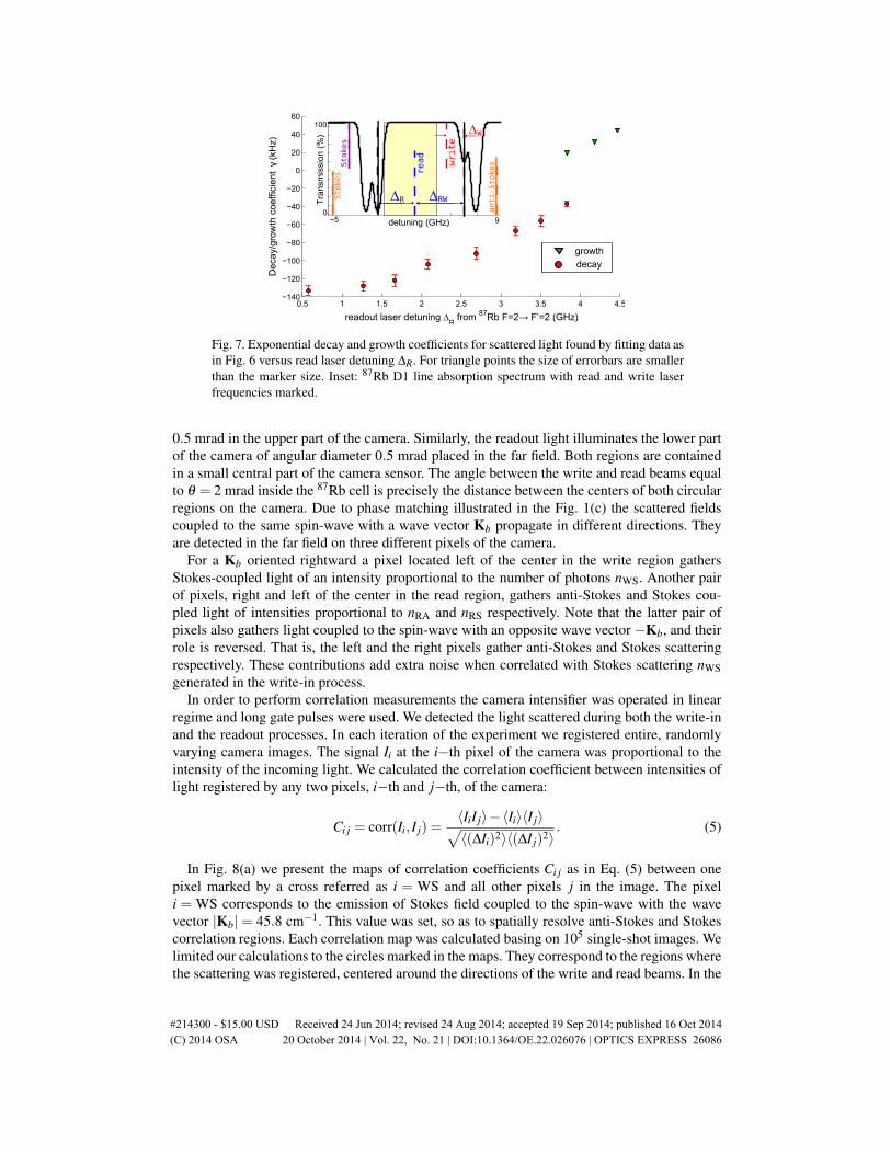
In Fig. 7 we plot decay and growth coefficients as functions of detuning ∆R of the read beamfrom F=2→F’=2 resonance. The coefficients were calculated by fitting exponential decay orgrowth to the first or the last 10 µs, as depicted in Fig. 6. Fitting entire 40 µs with a singleexponential fails because the significant influence of decoherence and multimode character ofscattering on this time scale is not capured by our simple thoeretical model. The dependenceof the growth and decay coefficients on the detuning ∆R agree qualitatively with predictions ofthe theoretical model as they rise along with ∆R. However, there is a discontinuity between thegrowth and decay coefficients at ∆R = 3.8 GHz that may be attributed to spin-wave decoherenceinfluence.
4.2. Spatial resolving of anti-Stokes and Stokes scattering
The analysis of intensity correlations between light scattered in various directions providesvaluable insight into the four-wave mixing at the readout. To set the stage we shall first recallthe relations between scattered photons directions. The scattering generated during the writepulse is emitted around the write beam and falls upon a circular region of angular diameter
#214300 - $15.00 USD Received 24 Jun 2014; revised 24 Aug 2014; accepted 19 Sep 2014; published 16 Oct 2014(C) 2014 OSA 20 October 2014 | Vol. 22, No. 21 | DOI:10.1364/OE.22.026076 | OPTICS EXPRESS 26085
growth
decay
0.5 1 1.5 2 2.5 3 3.5 4 4.5−140
−120
−100
−80
−60
−40
−20
0
20
40
60
readout’laser’detuning ∆R
from 87Rb’F=2→ F’=2’yGHz/
Dec
ay/g
row
th’c
oeffi
cien
tγ
ykH
z/
Fig. 7. Exponential decay and growth coefficients for scattered light found by fitting data asin Fig. 6 versus read laser detuning ∆R. For triangle points the size of errorbars are smallerthan the marker size. Inset: 87Rb D1 line absorption spectrum with read and write laserfrequencies marked.
0.5 mrad in the upper part of the camera. Similarly, the readout light illuminates the lower partof the camera of angular diameter 0.5 mrad placed in the far field. Both regions are containedin a small central part of the camera sensor. The angle between the write and read beams equalto θ = 2 mrad inside the 87Rb cell is precisely the distance between the centers of both circularregions on the camera. Due to phase matching illustrated in the Fig. 1(c) the scattered fieldscoupled to the same spin-wave with a wave vector Kb propagate in different directions. Theyare detected in the far field on three different pixels of the camera.
For a Kb oriented rightward a pixel located left of the center in the write region gathersStokes-coupled light of an intensity proportional to the number of photons nWS. Another pairof pixels, right and left of the center in the read region, gathers anti-Stokes and Stokes cou-pled light of intensities proportional to nRA and nRS respectively. Note that the latter pair ofpixels also gathers light coupled to the spin-wave with an opposite wave vector −Kb, and theirrole is reversed. That is, the left and the right pixels gather anti-Stokes and Stokes scatteringrespectively. These contributions add extra noise when correlated with Stokes scattering nWSgenerated in the write-in process.
In order to perform correlation measurements the camera intensifier was operated in linearregime and long gate pulses were used. We detected the light scattered during both the write-inand the readout processes. In each iteration of the experiment we registered entire, randomlyvarying camera images. The signal Ii at the i−th pixel of the camera was proportional to theintensity of the incoming light. We calculated the correlation coefficient between intensities oflight registered by any two pixels, i−th and j−th, of the camera:
Ci j = corr(Ii, I j) =〈IiI j〉−〈Ii〉〈I j〉√〈(∆Ii)2〉〈(∆I j)2〉
. (5)
In Fig. 8(a) we present the maps of correlation coefficients Ci j as in Eq. (5) between onepixel marked by a cross referred as i = WS and all other pixels j in the image. The pixeli = WS corresponds to the emission of Stokes field coupled to the spin-wave with the wavevector |Kb| = 45.8 cm−1. This value was set, so as to spatially resolve anti-Stokes and Stokescorrelation regions. Each correlation map was calculated basing on 105 single-shot images. Welimited our calculations to the circles marked in the maps. They correspond to the regions wherethe scattering was registered, centered around the directions of the write and read beams. In the
#214300 - $15.00 USD Received 24 Jun 2014; revised 24 Aug 2014; accepted 19 Sep 2014; published 16 Oct 2014(C) 2014 OSA 20 October 2014 | Vol. 22, No. 21 | DOI:10.1364/OE.22.026076 | OPTICS EXPRESS 26086
(a)
−0.5 −0.25 0 0.25 0.5 −0.5 −0.25 0 0.25 0.5−2
−1.5
−1
−0.5
0
0.5
1
1.5
2
−0.5 −0.25 0 0.25 0.5
Xofmradb
Yof
mra
db
∆R=1.17GHz ∆
R=2.75GHz ∆
R=3.28GHz
0.1
0.2
0.3
0.4
0.5
0.6
0.7
0.8
0.9
CWScRA
CWScRS
(b)Xofmradb Xofmradb
RS
RAWS
RS
RAWS
RS
RAWS
1 1.5 2 2.5 3 3.5
30
40
50
60
70
80
readoutolaserodetuning ∆R
from 87RboF=2→ F’=2ofGHzb
corr
elat
iono
coef
ficie
ntoC
WS
cRAcoC
WS
cRS
fnb
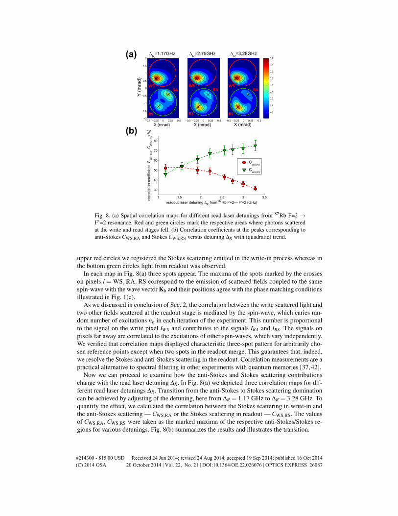
Fig. 8. (a) Spatial correlation maps for different read laser detunings from 87Rb F=2 →F’=2 resonance. Red and green circles mark the respective areas where photons scatteredat the write and read stages fell. (b) Correlation coefficients at the peaks corresponding toanti-Stokes CWS,RA and Stokes CWS,RS versus detuning ∆R with (quadratic) trend.
upper red circles we registered the Stokes scattering emitted in the write-in process whereas inthe bottom green circles light from readout was observed.
In each map in Fig. 8(a) three spots appear. The maxima of the spots marked by the crosseson pixels i = WS, RA, RS correspond to the emission of scattered fields coupled to the samespin-wave with the wave vector Kb and their positions agree with the phase matching conditionsillustrated in Fig. 1(c).
As we discussed in conclusion of Sec. 2, the correlation between the write scattered light andtwo other fields scattered at the readout stage is mediated by the spin-wave, which caries ran-dom number of excitations nb in each iteration of the experiment. This number is proportionalto the signal on the write pixel IWS and contributes to the signals IRA and IRS. The signals onpixels far away are correlated to the excitations of other spin-waves, which vary independently.We verified that correlation maps displayed characteristic three-spot pattern for arbitrarily cho-sen reference points except when two spots in the readout merge. This guarantees that, indeed,we resolve the Stokes and anti-Stokes scattering in the readout. Correlation measurements are apractical alternative to spectral filtering in other experiments with quantum memories [37, 42].
Now we can proceed to examine how the anti-Stokes and Stokes scattering contributionschange with the read laser detuning ∆R. In Fig. 8(a) we depicted three correlation maps for dif-ferent read laser detunings ∆R. Transition from the anti-Stokes to Stokes scattering dominationcan be achieved by adjusting of the detuning, here from ∆R = 1.17 GHz to ∆R = 3.28 GHz. Toquantify the effect, we calculated the correlation between the Stokes scattering in write-in andthe anti-Stokes scattering — CWS,RA or the Stokes scattering in readout — CWS,RS. The valuesof CWS,RA, CWS,RS were taken as the marked maxima of the respective anti-Stokes/Stokes re-gions for various detunings. Fig. 8(b) summarizes the results and illustrates the transition.
#214300 - $15.00 USD Received 24 Jun 2014; revised 24 Aug 2014; accepted 19 Sep 2014; published 16 Oct 2014(C) 2014 OSA 20 October 2014 | Vol. 22, No. 21 | DOI:10.1364/OE.22.026076 | OPTICS EXPRESS 26087

4.3. Effective gains of anti-Stokes and Stokes readout
The measured correlation values together with mean intensities and their variances can be usedto extract information about time integrated readout gains for the anti-Stokes GRA and StokesGRS separately. This is accomplished by tracing the origins of signal observed at respectivepixels.
The signal IWS registered at pixel i = WS was calibrated to the number of photons. It consistsof the part proportional to the number of photons nWS generated during the write-in to the spin-wave of the wave vector Kb and the camera system read noise fWS:
IWS = tWSnWS + fWS, (6)
where tWS is the transmission of the write-in Stokes photons through the filter system. The readnoise fWS is random and its variance depends only on the intensity on the pixel 〈(∆ fi)
2〉 ∼ I2i .
We made the calibration of the noise prior to the measurements, which allowed us to exactlydetermine the variance of the read noise at each pixel.
The signal in the readout at pixel i=RA can be decomposed into the following contributions:
IRA = tRAnRA + tRSn′RS + fRA, (7)
where nRA is the number of photons generated in the anti-Stokes readout from the spin waveof the wave vector Kb and n′RS is the number of photons generated in the Stokes readout fromthe other spin wave with the opposite wave vector −Kb, illuminating the same pixel. tRA andtRS are respectively the transmissions of the anti-Stokes and the Stokes photons and fRA is thecamera system read noise at the pixel i = RA.
We can write an analogous formula for the components of the signal registered at the pixeli = RS:
IRS = tRSnRS + tRAn′RA + fRS. (8)
In the actual experiment the number of created spin-wave excitations nb is smaller than thenumber of scattered photons nWS due to decoherence at the write-in stage nb = ηWnWS. Thatfactor ηW is write-in efficiency. In turn, the decoherence at the readout stage leads to a limitedefficiency ηR during this process. We include those efficiencies in the formula Eq. (4), whichyields the phenomenological formulas for the number of retrieved photons:
nRA = ηWηRGRAnWS + SRA, (9)
nRS = ηWηRGRSnWS + SRS, (10)
where GRAand GRS are the time integrated gains and SRAand SRS is the spontaneous emis-sion generated at the readout introduced in the theoretical model. The factors ηWηRGRA andηWηRGRS are the effective gains of the anti-Stokes and the Stokes readouts in the experiment.
Eqs. (7)-(10) and simple observations that corr(nWS,ηWηRGRAnWS) = 1 and corr(nWS, Si) =corr(nWS,n′i) = corr(nWS, fi) = 0 allow us to calculate the effective gains from the measuredquantities:
ηWηRGRA =tWS
tRA
CWS,RA√〈(∆IWS)2〉〈(∆IRA)2〉
〈(∆IWS)2〉−〈(∆ fWS)2〉, (11)
ηWηRGRS =tWS
tRS
CWS,RS√〈(∆IWS)2〉〈(∆IRS)2〉
〈(∆IWS)2〉−〈(∆ fWS)2〉. (12)
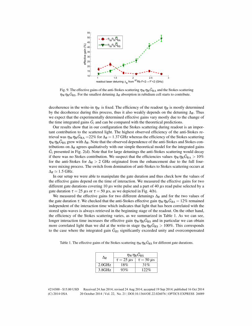
The above formulas can be verified by evaluating the numerators of the right hand sides.In Fig. 9 we present the results of the effective gains of the anti-Stokes scattering ηWηRGRA
and the Stokes scattering ηWηRGRS for different read laser detunings ∆R. The efficiency due to
#214300 - $15.00 USD Received 24 Jun 2014; revised 24 Aug 2014; accepted 19 Sep 2014; published 16 Oct 2014(C) 2014 OSA 20 October 2014 | Vol. 22, No. 21 | DOI:10.1364/OE.22.026076 | OPTICS EXPRESS 26088
1 1.5 2 2.5 310
15
20
25
30
35
40
45
50
55
readoutGlaserGdetuning ∆R
from 87RbGF=2→ F’=2GSGHz)ef
fect
iveG
gain
GSv
)
ηWη
RG
RA
ηWη
RG
RS
Fig. 9. The effective gains of the anti-Stokes scattering ηWηRGRA and the Stokes scatteringηWηRGRS. For the smallest detuning ∆R absorption in rubidium cell starts to contribute.
decoherence in the write-in ηW is fixed. The efficiency of the readout ηR is mostly determinedby the decoherece during this process, thus it also weakly depends on the detuning ∆R. Thuswe expect that the experimentally determined effective gains vary mostly due to the change ofthe time integrated gains Gi and can be compared with the theoretical predictions.
Our results show that in our configuration the Stokes scattering during readout is an impor-tant contribution to the scattered light. The highest observed efficiency of the anti-Stokes re-trieval was ηWηRGRA =22% for ∆R = 1.37 GHz whereas the efficiency of the Stokes scatteringηWηRGRS grew with ∆R. Note that the observed dependence of the anti-Stokes and Stokes con-tributions on ∆R agrees qualitatively with our simple theoretical model for the integrated gainsGi presented in Fig. 2(d). Note that for large detunings the anti-Stokes scattering would decayif there was no Stokes contribution. We suspect that the efficiencies values ηWηRGRA > 10%for the anti-Stokes for ∆R > 2 GHz originated from the enhancement due to the full four-wave mixing process. The switch from domination of anti-Stokes to Stokes scattering occurs at∆R ' 1.5 GHz.
In our setup we were able to manipulate the gate duration and thus check how the values ofthe effective gains depend on the time of interaction. We measured the effective gains for twodifferent gate durations covering 10 µs write pulse and a part of 40 µs read pulse selected by agate duration τ = 25 µs or τ = 50 µs, as we depicted in Fig. 4(b).
We measured the effective gains for two different detunings ∆R and for the two values ofthe gate duration τ . We checked that the anti-Stokes effective gain ηWηRGRA = 12% remainedindependent of the interaction time which indicates that light that has been correlated with thestored spin-waves is always retrieved in the beginning stage of the readout. On the other hand,the efficiency of the Stokes scattering varies, as we summarized in Table 1. As we can see,longer interaction time increases the effective gain ηWηRGRS and in particular we can obtainmore correlated light than we did at the write-in stage ηWηRGRS > 100%. This correspondsto the case where the integrated gain GRS significantly exceeded unity and overcompensated
Table 1. The effective gains of the Stokes scattering ηWηRGRS for different gate durations.
∆RηWηRGRS
τ = 25 µs τ = 50 µs2.0GHz 18% 31%3.8GHz 93% 122%
#214300 - $15.00 USD Received 24 Jun 2014; revised 24 Aug 2014; accepted 19 Sep 2014; published 16 Oct 2014(C) 2014 OSA 20 October 2014 | Vol. 22, No. 21 | DOI:10.1364/OE.22.026076 | OPTICS EXPRESS 26089
for the losses, albeit bringing a large amount of accompanying noise SRS. Such a high gain ofthe obtained signal can find an application in various operations with quantum memories. Forinstance the dominant Stokes scattering process can be utilized for testing if the memory isempty. No photons retrieved from the memory at the readout may suggest that memory wasinitially empty with a certain probability. This probability is much higher for amplified readoutwith Stokes interaction dominant as opposed to conventional pure anti-Stokes readout processof limited efficiency.
5. Conclusions
In conclusion, we have presented an experimental demonstration of manipulation of the Hamil-tonian in the readout from Raman-type atomic memory. We measured the temporal evolution ofthe readout light and the spatial correlations between the Raman scattering in the write-in andthe readout. Our measurements confirm the adjustability of coupling parameters correspondingto the anti-Stokes and Stokes scattering. The results match our simple theoretical model of afull four-wave mixing process. We resolved the anti-Stokes and the Stokes scattering contribu-tions to the readout thanks to the phase matching in the atomic vapor which dictated directionalcorrelations with the Stokes photons during write-in.
Our results provide a very simple framework for interpretation of extra noise in experimentson storing light in atomic vapor. When anti-Stokes scattering is used to map the spin-wave statesonto the states of light, the accompanying Stokes scattering creates unwanted random photonsand atomic excitations. Our results show that, though inevitable, this contribution can be esti-mated by our model and perhaps suppressed by adjusting the coupling light frequency to theother side of the atomic resonance. There is also an optimal duration for the anti-Stokes interac-tion. Beyond the optimum, the spontaneous noise contribution increases. It may be favorable toswitch to noncollinear configuration where control and quantum fields enter the atomic mediumat a small angle. Then the Stokes scattering photons will become directionally distinguishablefrom the anti-Stokes, which may lower the noise in some experiments.
The design of the Hamiltonian we demonstrated can be implemented in many types of quan-tum memories at little or no extra cost. The amplification of readout signal by Stokes scatteringmay be very useful in some applications especially if extra noise is not crucial. This is the casewhen we use detectors of small quantum efficiency or we are focused on other properties ofretrieved light e.g. in retrieval of stored images [23, 43]. For instance the amplification in thereadout can be utilized as a robust single-shot projective test to see whether the atomic memoryis in the ground (empty) state. A complete absence of Stokes signal on an inefficient detectoris a relatively rare occurrence if the extra Stokes gain overcompensates for the losses at thedetection stage. Notably then, complete absence of signal ensures us that the memory was inthe ground state.
Our results can be useful for suppressing unconditional noise floor in readout of Raman-typequantum memories at the single photon level [13, 25, 44]. We provide evidence for a possibil-ity of engineering a wide range of atom-light interfaces which can be described theoreticallyas simultaneous readout and parametric amplification e.g. quantum non-demolition interactionwhile coupling coefficients are equal. The facility to continuously tune the Hamiltonian co-efficients sets the scene for developing new quantum protocols in room-temperature atomicmemories.
Acknowledgments
We acknowledge J. Nunn for the insightful discussion and C. Radzewicz and K. Banaszek forgenerous support. The project was financed by the National Science Centre projects no. DEC-2011/03/D/ST2/01941 and DEC-2013/09/N/ST2/02229.
#214300 - $15.00 USD Received 24 Jun 2014; revised 24 Aug 2014; accepted 19 Sep 2014; published 16 Oct 2014(C) 2014 OSA 20 October 2014 | Vol. 22, No. 21 | DOI:10.1364/OE.22.026076 | OPTICS EXPRESS 26090