Embed Size (px)
Citation preview

Hamilton Canal Innovation District Walker Consultants Parking Structure Addendum No. 7 Construction Documents Lowell, MA October 12, 2018 June 26, 2018
©2018, Walker Consultants. All rights reserved. TABLE OF CONTENTS 000110 - 1
SECTION 000110 – TABLE OF CONTENTS – TECHNICAL SPECIFICATIONS
DIVISION 00 – PROCUREMENT AND CONTRACTING AGREEMENTS
INTRODUCTORY INFORMATION 000110 Table of Contents 000115 List of Drawing Sheets
CONTRACTING REQUIREMENTS 007355 EPA NPDES General Permit for Construction Activities
DIVISION 01 - GENERAL REQUIREMENTS
011100 Summary of Work 012200 Unit Prices 012600 Contract Modification Procedures 012900 Payment Procedures 013100 Project Management and Coordination 013200 Construction Progress Documentation 013233 Photographic Documentation 013300 Submittal Procedures 013529 Environmental Health & Safety 014000 Quality Control 014200 References 014210 Reference Standards and Definitions 015000 Temporary Facilities and Controls 016000 Product Requirements 016010 Product Substitution Procedure 017300 Execution 017700 Closeout Procedures 017823 Operation and Maintenance Data 017839 Project Record Documents 017900 Demonstration and Training 018900 Site Construction Performance Requirements
DIVISION 02 – EXISTING CONDITIONS
023000 Subsurface Information
026113 Excavated Soil and Material Management Plan
DIVISION 03 – CONCRETE 033000 Cast-in-Place Concrete 033010 Cast-in-place Concrete (Site) 034100 Precast Structural Concrete 036400 Injection Grouting

Hamilton Canal Innovation District Walker Consultants Parking Structure Addendum No. 7 Construction Documents Lowell, MA October 12, 2018 June 26, 2018
©2018, Walker Consultants. All rights reserved. TABLE OF CONTENTS 000110 - 2
DIVISION 04 - MASONRY
040001* Masonry (Trade Contract Required.) 042221* Reinforced Concrete Masonry Assemblies (Trade Contract Required.)
DIVISION 05 – METALS
050001* Miscellaneous & Ornamental Iron (Trade Contract Required.) 050800 Factory Applied Metal Coatings 050850* Hot Dipped Galvanizing (Trade Contract Required.) 050860* Shop Coatings on Galvanizing (Trade Contract Required.) 051200 Structural Steel Framing 051617 Strand Guardrail System 053100 Steel Decking 054000 Cold-Formed Metal Framing 055000* Metal Fabrications (Trade Contract Required.) 055080* Pipe Bollards (Trade Contract required.) 055150* Ladders (Trade Contract Required.) 055210* Steel & Aluminum Railing Assemblies (Trade Contract Required.) 055350* Metal Gratings (Trade Contract Required.)
DIVISION 06 – WOOD, PLASTICS AND COMPOSITES
060800 Wood Preservative & Fire Retardant Treatments 061050 Wood Blocking 061620 Gypsum Sheathing
DIVISION 07 - THERMAL AND MOISTURE PROTECTION 070001* Waterproofing, Dampproofing & Caulking (Trade Contract Required.) 070002* Roofing & Flashing (Trade Contract Required.) 071113* Bituminous Dampproofing (Trade Contract Required.) 071413* Hot Fluid-Applied Rubberized Asphalt Waterproofing (Trade Contract Required.) 071416* Cold Fluid-Applied Waterproofing (Trade Contract Required.) 071616* Crystalline Waterproofing (Trade Contract Required.) 071800* Traffic Coatings (Trade Contract Required.) 071900* Water Repellents (Trade Contract Required.) 072100 Thermal Insulation 072728* Self-Adhering Sheet Air Barriers (Trade Contract Requird.) 074245 Composite Aluminum Panels 074266 Fabricated Solid & Perforated Aluminum Plate Wall Panels 074320 High Density Cement Wall Panels 075419* Adhered PVC Membrane Roofing (Trade Contract Required.) 076200* Sheet Metal Flashing and Trim (Trade Contract Required.) 078100 Applied Spray Fireproofing 078120 Thin Film Fireproofing 078400 Fire/Smoke Stopping 079221 Acoustical Joints Sealants 079233* Concrete Joint Sealants (Trade Contract Required.) 079236* Architectural Joint Sealants (Trade Contract Required.)

Hamilton Canal Innovation District Walker Consultants Parking Structure Addendum No. 7 Construction Documents Lowell, MA October 12, 2018 June 26, 2018
©2018, Walker Consultants. All rights reserved. TABLE OF CONTENTS 000110 - 3
079500* Expansion Joint Assemblies (Trade Contract Required.)
DIVISION 08 - OPENINGS
080001* Metal Windows (Trade Contract Required.) 081110 Steel Doors and Frames 084120* Fire Rated Aluminum-Steel Storefronts (Trade Contract Required.) 084220* Aluminum-Framed Entrances (Trade Contract Required.) 084310* Interior Aluminum Framed Storefronts (Trade Contract Required.) 084410* Glazed Aluminum Curtain Walls (Trade Contract Required.) 085652* Transaction Windows (Trade Contract Required.) 087100 Door Hardware 088010* Exterior Glass (Trade Contract Required.) 088020* Interior Glass (Trade Contract Required.) 088030 Mirrors 089119 Fixed Louvers
DIVISION 09 – FINISHES 090002* Tile (Trade Contract Required.) 090007* Painting (Trade Contract Required.) 091000 Non-Structural Light Gage Steel Framing 091050 Metal Blocking 092800 Interior Tile Backer Board 092900 Gypsum Board 093000* Tiling (Trade Contract Required.) 095110 Acoustical Panel Ceilings 095414 Lay-in Open Cell Metal Ceilings 096510 Resilient Base 096517 Linoleum Sheet Flooring 096550 Resilient Flooring Installation 098110 Acoustical Insulation & Accessories 099120* Pavement Marking (Garage) (Trade Contract Required.) 099123* Interior Painting (Trade Contract Required.)
DIVISION 10 – SPECIALTIES
101400 Signage 101455 Traffic and Regulatory signage (Site) 102800 Toilet, Bath and Laundry Accessories 104400 Fire Protection Specialties 107620 Flexible Delineator Posts 108113 Bird Control Devices
DIVISION 11 – EQUIPMENT 111233.00 Automated PARCS 112416 Roof Anchor Window Washing Support Assemblies
DIVISION 12 – FURNISHINGS
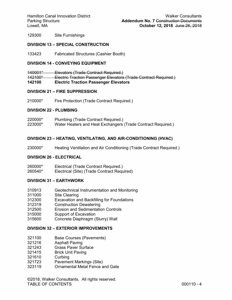
Hamilton Canal Innovation District Walker Consultants Parking Structure Addendum No. 7 Construction Documents Lowell, MA October 12, 2018 June 26, 2018
©2018, Walker Consultants. All rights reserved. TABLE OF CONTENTS 000110 - 4
129300 Site Furnishings
DIVISION 13 – SPECIAL CONSTRUCTION
133423 Fabricated Structures (Cashier Booth)
DIVISION 14 - CONVEYING EQUIPMENT
140001* Elevators (Trade Contract Required.) 142100* Electric Traction Passenger Elevators (Trade Contract Required.) 142100 Electric Traction Passenger Elevators
DIVISION 21 – FIRE SUPPRESSION
210000* Fire Protection (Trade Contract Required.)
DIVISION 22 - PLUMBING
220000* Plumbing (Trade Contract Required.) 223000* Water Heaters and Heat Exchangers (Trade Contract Required.)
DIVISION 23 – HEATING, VENTILATING, AND AIR-CONDITIONING (HVAC)
230000* Heating Ventilation and Air Conditioning (Trade Contract Required.)
DIVISION 26 - ELECTRICAL
260000* Electrical (Trade Contract Required.) 260540* Electrical (Site) (Trade Contract Required)
DIVISION 31 – EARTHWORK 310913 Geotechnical Instrumentation and Monitoring 311000 Site Clearing 312300 Excavation and Backfilling for Foundations 312319 Construction Dewatering 312500 Erosion and Sedimentation Controls 315000 Support of Excavation 315600 Concrete Diaphragm (Slurry) Wall
DIVISION 32 – EXTERIOR IMPROVEMENTS 321100 Base Courses (Pavements) 321216 Asphalt Paving 321243 Grass Paver Surface 321415 Brick Unit Paving 321610 Curbing 321723 Pavement Markings (Site) 323119 Ornamental Metal Fence and Gate

Hamilton Canal Innovation District Walker Consultants Parking Structure Addendum No. 7 Construction Documents Lowell, MA October 12, 2018 June 26, 2018
©2018, Walker Consultants. All rights reserved. TABLE OF CONTENTS 000110 - 5
328000 Irrigation 329000 Planting 329113 Structural Planting Medium 329220 Seeding and Sodding 329500 Wilshire Box Linear Planter System
DIVISION 33 – UTILITIES
331000 Water Utilities 333900 Sanitary Utility Sewerage Structures 334000 Storm Drainage Utilities 334020 Warning and Tracer Tape 334613 Underslab Drainage System
DIVISION 34 – TRANSPORTATION
347113 Vehicle Barriers
END OF TABLE OF CONTENTS
Copyright 2018. All rights reserved. No part of this document may be reproduced in any form or by any means without permission from Walker Consultants.

Hamilton Canal Innovation District Walker Consultants Parking Structure Addendum No. 7 Construction Documents Lowell, MA October 12, 2018 June 26, 2018
©2018, Walker Consultants. All rights reserved. TABLE OF CONTENTS 000110 - 6
THIS PAGE INTENTIONALLY LEFT BLANK

Hamilton Canal Innovation District Fennick | McCredie Parking Structure Construction Documents Lowell, MA June 26, 2018 ©2018 Putnam Associates Specifiers
HIGH DENSITY CEMENT WALL PANELS 07 43 20 - 1 OF 8
SECTION 07 43 20 - HIGH DENSITY CEMENT WALL PANELS
PART 1 GENERAL
1.1 SUMMARY
A. Related Documents: Drawings and general provisions of the Contract, including General and Supplementary Conditions and Division 1 Specification Sections, apply to this Section.
B. Section includes, without limitation, providing: 1. High density cement composite wall panels. 2. Fastening. 3. Joint inserts. 4. Accessories 5. Aluminum decorative trim and related components. 6. Sub-framing and support assemblies 7. Delegated structural design. 8. Rainscreen system.
C. Extent: Where indicated, if not, at: 1. Wall panel cladding, face fastened assembly. 2. Custom texture and custom color.
D. Related sections include: 1. Division 01 – Sections related to envelop performance. 2. Section 07 21 00 Thermal insulation. 3. Section 07 27 28 Self adhering sheet air barrier 4. Section 07 84 00 Fire / smoke stopping. 5. Section 08 44 10 Glazed aluminum curtain wall.
1.2 DEFINITIONS
A. For the purposes of this project, the words “high density cement panels” and “fiber cement panels” shall refer to the types of products specified in this section, i.e., a through color panel with a dry density of at least 98.6 pounds per cubic foot.
1.3 PERFORMANCE CRITERIA
A. Strength: The panels will be fabricated to withstand loadings indicated on plans, but not less than the following minimum loadings. 1. Wind loading: As shown on the structural drawings.
B. Condensation: Panels shall accommodate positive drainage for moisture entering or condensation occurring within panel system.
1.4 SYSTEM REQUIREMENTS
A. General: Fabricate and install components (specifically related to the system described herein) so that the completed exterior wall assembly will withstand live loads, the inward and outward pressures specified, and loads stipulated by the plans for this Project. 1. The wall assembly shall have a design load of positive and negative pressures up to
40 psf. 2. Deflections within the assembly are to be limited to L/240 or less when tested in
Addendum No. 7October 12, 2018

Hamilton Canal Innovation District Fennick | McCredie Parking Structure Construction Documents Lowell, MA June 26, 2018 ©2018 Putnam Associates Specifiers
HIGH DENSITY CEMENT WALL PANELS 07 43 20 - 2 OF 8
accordance with ASTM E330 for positive and negative pressures and as required to prevent cracking or damage to panel facing.
3. The exterior wall assembly shall be installed to meet all specified performance requirements of ASTM E330. Where performance requirements result in more than one load or pressure, the load or pressure that produces the greatest stress shall govern.
4. All vertical members, horizontal sub-construction components, bearing constructions, reinforcements, etc., must be determined within a structural evaluation suited to the respective building project and taking into consideration the building height, exposure and the wind loads.
B. Movement: Fabricate and install components to withstand building and thermal movements including loading deflections, temperature change without buckling, distortion, joint failure, or undue stress on assembly components, anchors or permanent deformation to outward force. Provide for thermal movement over an ambient temperature range of 120 deg. F. and a surface temperature range of 180 deg. F.
1.5 SUBMITTALS
A. Product Data: Submit manufacturer's product data and installation instructions, restrictions and limitations for each material and product used.
B. Shop Drawings: Submit shop drawings indicating layout, profiles and product components, including edge conditions, panel joints, fixture location, anchorage, accessories, finish colors, patterns and textures 1. Field Measurements: Verify actual measurements/openings by field measurements
before fabrication; show recorded measurements on shop drawings. Coordinate field measurements and fabrication schedule with construction progress to avoid construction delays.
2. Submit drawings stamped by engineer registered in the jurisdiction.
C. Maintenance data: Maintenance, and cleaning information
D. Samples: Submit two representative samples of each material specified indicating visual characteristics and finish. Include range samples if variation of finish is anticipated.
E. Warranty: Submit manufacture’s standard warranty. Include labor and materials to repair or replace defective materials. 1. Warranty Period: 10 years.
1.6 QUALITY ASSURANCE
A. Comply with governing codes and regulations. Provide products of acceptable manufacturers which have been in satisfactory use in similar service for three years. Use experienced installers, approved by manufacturer. Deliver, handle, and store materials in accordance with manufacturer's instructions.
B. Engage a design professional licensed in the project’s jurisdiction to design system and components.
C. Dimensional Tolerances: 1. Sheet size tolerance: Plus or minus 1/8 inch. 2. Thickness tolerance: Plus or minus 1/16 inch. 3. Riven textured surface: An additional plus or minus 1/16 inch. 4. Structural: Provide components that have been tested in accordance with ASTM
Addendum No. 7October 12, 2018

Hamilton Canal Innovation District Fennick | McCredie Parking Structure Construction Documents Lowell, MA June 26, 2018 ©2018 Putnam Associates Specifiers
HIGH DENSITY CEMENT WALL PANELS 07 43 20 - 3 OF 8
E330 at a design pressure of 40 psf without permanent deformation or failures of structural members.
5. Wind Load design: Panels designed to meet building code wind loads and the following: a. Not less than 20 psf wind load and 30 psf on parapets and corners, per ASTM
E330. b. Deflection of perimeter framed members: Not to exceed L/175 or 0.75 inch,
whichever is less, when measured normal to plane of wall between supports. c. Deflection of full span: Not to exceed L/60, when measured normal to wall
plane. d. Maximum anchor deflection: 1/16 inch.
D. Multi-story fire test standard: Where required by drawings or code, comply with NFPA 285 and UL S134.
E. Severe weather approval: Provide Miami Dade County Product Control Approval.
F. Shipping and finish protection: Provide protective foils unless manufacturer does not recommend their use.
G. Mock-up: Install at project site a job mock-up using acceptable products and manufacturer approved installation methods. Obtain Owner’s and Architect’s acceptance of finish color, texture, pattern and workmanship standards. Acceptable mock-ups may be incorporated into the work at project completion.
H. Pre-installation meeting: Conduct preinstallation meeting to verify project requirements, substrate conditions, manufacturer’s installation instructions and manufacturer’s warranty requirements.
1.7 PRODUCT REQUIREMENTS
A. Delivery: 1. Deliver panels in crates on wood pallets, interwoven with protective paper and
wrapped in plastic sheets. 2. Materials shall be packaged to minimize or
eliminate the possibility of damage during shipping. Items such as wooden side boards, wooden lid, and spacers or protective sheeting between panels shall be used to protect the panels from surface and/or edge damage.
3. Store panels flat in original shipping crates or on wood pallets under protective cover until needed for installation. Elevate above grade on level blocking to avoid standing water.
B. Storage: 1. Store products in an enclosed area
protected from direct sunlight, moisture and heat. 2. Maintain a consistent temperature and humidity. 3. Store products in manufacturer's unopened packaging until ready for installation. 4. Stack panels using protective dividers to avoid damage to decorative surface. 5. For horizontal storage, store sheets on pallets of equal or greater size as the sheets
with a protective layer between the pallet and sheet and on top of the uppermost sheet.
6. Do not store sheets, or fabricated panels vertically. 7. Ventilate coverings to avoid condensation.
Addendum No. 7October 12, 2018

Hamilton Canal Innovation District Fennick | McCredie Parking Structure Construction Documents Lowell, MA June 26, 2018 ©2018 Putnam Associates Specifiers
HIGH DENSITY CEMENT WALL PANELS 07 43 20 - 4 OF 8
C. Handling: 1. Protect panels from scuffing during handling, and apply manufacturer's
recommended remedial treatment immediately if panels are soiled or scratched. Carry panels on edge and handle carefully to avoid damage to surfaces and corner.
2. Remove all labels and stickers immediately after installation.
1.8 WARRANTY
A. Provide manufacturer’s standard 10 year warranty.
PART 2 PRODUCTS
2.1 HIGH DENSITY CEMENT COMPOSITE WALL PANELS
A. Basis of Design: 1. Manufacturer: Equitone based upon “Natura”. 2. Panel type: Rectified. 3. Unless otherwise indicated, base pricing on: Integrally colored, in stock color. 4. Coating: As per product specified or selected.
B. Available Manufacturers and products: Subject to compliance with requirements: 1. SoLiX Group AB – Cembrit Holding A/S, “Cembrit True/Transparent” an
integrally colored panel with a transparent topcoat. 2. SwissPearl Group; www.swisspearl.com, “SwissPearl Carat”, an integrally
colored with a translucent lightly pigmented top layer. 3. Equitone, www.equitone.com/, “Equitone Natura”. 4. Unless otherwise indicated, base pricing on: Integrally colored, in stock color.
C. Attachment method: Face fastener, and riveted, manufacturer recommended components.
D. Material: 1. Composition/construction:
a. Base material: Portland cement, ground limestone – 65% minimum. b. Fiber reinforcing: Polyvinyl alcohol fibers and cellulose fibers. c. Coatings: Acrylic to panel face, rear, and edges.
2. Color: Homogeneous throughout. 3. Typical Thickness: 5/16 inch. 4. Special Thickness: 1/2 inch where shown, including perforated panels. 5. Sheet size: Up to 48 x 120 inches, nominal. 6. Panel size: As shown on drawings. 7. Weight: Approx. 3.5 pounds per square foot. 8. Performance:
a. Flame Spread: 15, per ASTM E 84. b. Fuel Contribution: 0, per ASTM E 84. c. Moisture Absorption: Maximum 0.2% by weight after 24 hours immersion. d. Biological Resistance: Immune to insect and vermin attack; inhibits mold
growth. e. Chemical Resistance: Impervious to most acid and organic solvents
9. Autoclaved product: Required. 10. Texture: Selected by Architect from stock surfaces. 11. Color: Selected by Architect from stock colors, including grey. 12. Unacceptable characteristics:
Addendum No. 7October 12, 2018

Hamilton Canal Innovation District Fennick | McCredie Parking Structure Construction Documents Lowell, MA June 26, 2018 ©2018 Putnam Associates Specifiers
HIGH DENSITY CEMENT WALL PANELS 07 43 20 - 5 OF 8
a. Autoclaved products. b. Products reinforced with cellulose only. c. Products exhibiting efflorescent during warranty period.
E. EQUITONE Natura product type / series characteristics: 1. Finish:
a. Integral color: Yes, through colored base board. b. Finish/Coating: Semi-transparent colored finish reveals structure of fibre
cement. c. Top coat: PU top-coat UV hardened hard surface finish with scratch
resistance and “anti graffiti” protection. d. Performance: Weatherproof and UV-stable. e. Rear inboard face: Transparent, back-sealed coating.
2. Physical Characteristics: a. Meets ASTM C1185, ASTM C1186, EN 12467 'Fibre-cement flat sheets'. b. Density Dry: Minimum 1.65 kg/m³ (103 lb/ft³) c. Bending strength @ ambient, perpendicular: 26.0 N/mm² (3,771 lbf/in²) d. Bending strength @ ambient, parallel: 17 N/mm2. (2,465 lbf/in²) e. Modulus of elasticity @ ambient, perpendicular: > 2,175,570 lbf/in² f. Hygric movement 0-100%, mean: 1.60 mm/m. g. Porosity 0-100%: < 20 %. h. Durability classification (EN 12467): Category A. i. Strength classification (EN 12467): Class 4. j. Fire reaction (EN 13501-1): A2-s1-d0; k. ASTM E84-Zero Flame Spread and smoke development of < 5; l. ASTM E-136 - passed. m. Impermeability test: Ok. n. Warm water test: Ok. o. Soak dry test: Ok. p. Freeze thaw test: Ok. q. Thermal conductivity: 0.6 W/mK.
F. Attachment system: As shown, if not as follows: 1. Face Fastened System: Equitone rivet system for panels.
a. Metal Framing: No. 10 or No. 6 square drive, flat head, Tek point 410 stainless steel screws in lengths to suit application.
b. Diamond Countersink Tool to suit screw size. c. Screws set depth: As recommended by manufacturer. d. Countersink filler: Manufacturer provided compound to match selected
color.
G. Sub-Frame System: 1. Aluminum Vertical Wall Brackets: 80% recycled 6063-T5 alloy. 0.125 in
thickness, Kynar coated as selected by Architect. 2. No. 10-16 x 3/4 Phillips, pan head, self drilling, 304 stainless steel for Wall
Bracket to Rail fastening. 3. No. 12-14 5/16 Hex Washer HD 304 stainless steel for Wall Bracket to Building
fastening. 4. TEN66 Omega / Zed System or equal: 0.093 in thickness Aluminum Top Hat
Section and "Z" Section. Provides a 1.57 inch fixed cavity depth.
H. Fasteners:
Addendum No. 7October 12, 2018

Hamilton Canal Innovation District Fennick | McCredie Parking Structure Construction Documents Lowell, MA June 26, 2018 ©2018 Putnam Associates Specifiers
HIGH DENSITY CEMENT WALL PANELS 07 43 20 - 6 OF 8
1. Supplied in accordance with latest product recommendations to meet load requirements specified.
2. Material: stainless steel.
I. Attachment System Components: Fabricator designed, for indicated fastening. 1. Material: 6063-T6 extruded aluminum channels, kynar coated, painted black or
other architect selected color, with minimum thickness of 1/8 inch (3.2 mm). 2. Finish: As shown, if not, kynar resin coated of type. 3. Minimum cavity for free air back vented system: As shown, if not,1 inch. 4. Profiles: As required by structural design. 5. Components: Include perimeter extrusions, panel stiffeners, panel clips and
anchor channels. 6. Spacing: Do on exceed manufacturer attachment spacing recommendations. 7. Fastener spacing: As recommended by manufacturer and as required by
structural design performed by fabricator. 8. Panel fastener hole sizes: 0.216 [5.5 mm] inches for fixed and 0.334 [8.5mm]
inches for oversized holes. 9. Provide fixed point and slip point fastener holes in recommended locations.
J. Trim: Provide shapes, plates and the like of shop formed aluminum matching other specified assemblies and kynar coated per Section 05 08 00 Type 4..
K. Fasteners: Supplied in accordance with latest product recommendations to meet load requirements specified 1. Fasteners for Wall Panels: Stainless steel self-drilling or self-tapping, flat or pan
head screws. 2. Fasteners for Flashing and Trim: Blind fasteners or self-drilling screws with hex
washer head. 3. Blind Fasteners: Stainless-steel rivets. 4. Exposed fasteners: Factory-applied powder coated to match panel color and
texture. 5. Spacers: Neoprene, size and length as needed. Provide where required.
L. Mounting Systems: As shown, if not: 1. TS110 - Exposed fastening on fixed depth aluminum sub-framing.
2.2 FABRICATION
A. Factory fabricate panels and assembly in accordance with manufacturer’s recommendations and approved submittals to profiles, shapes and sizes required.
B. Provide factory fabricated panels to extent possible, conforming to following: 1. Cut to custom sizes from manufacturer's standard sizes. 2. Pre-drill and countersink fastener holes. 3. Prepare special shapes and cutouts. 4. Polish, bevel, or miter edges, as required. 5. Prefabricate inside and outside corners. 6. Prepare inserts and brackets for back fastening system. 7. Bond insulating materials to panels, if indicated.
C. Perform shop or site cutting using a saw equipped with a dry cut, diamond tipped blade. When using a portable or table saw, place finished side up. When using a moveable, portable skill saw, place finished side down. Clamp to saw bed before cutting. Radius cuts can be made Use abrasive jig saw blade with carbide chips for
Addendum No. 7October 12, 2018

Hamilton Canal Innovation District Fennick | McCredie Parking Structure Construction Documents Lowell, MA June 26, 2018 ©2018 Putnam Associates Specifiers
HIGH DENSITY CEMENT WALL PANELS 07 43 20 - 7 OF 8
radius cuts.
D. When on-site drilling or countersinking cannot be avoided, drill panels with portable hand-held pistol drill equipped with a drill guide to assure 90 degree holes and masonry drill bit suitable for drilling at speeds of 900 to 1200 rpm.
E. Remove sawdust from panel surfaces immediately.
PART 3 - EXECUTION
3.1 EXAMINATION
A. Verify proper installation of weather barrier and that sheathing is sufficiently plumb, plane and true to required tolerances.
3.2 INSTALLATION - GENERAL
A. Install materials and systems in accordance with manufacturer's instructions and approved submittals. Coordinate with work of other sections. Install materials and systems in proper relation with adjacent construction and with uniform appearance and as follows: 1. Install girt/support and anchoring systems true and plumb in order to provide
support for wall panels. 2. Install panels with open joints, and as follows:
a. Fabricated Joints: Allow a minimum 1/2 inch (12.7 mm) of free space for movement of panels, unless otherwise shown or recommended.
b. Vertical joints: Provide support elements directly behind joint. c. Coordinate exact sizes and dimensions with the drawings, field conditions and
approved shop drawings. 3. At rainscreen assemblies, provide a perforated screen ventilation at every vertical
section of façade cladding at bottom and top, having a free area 2.36 square inches per linear foot.
B. Do not install panels or component parts which are observed to be defective or damaged including, but not limited to: warped, bowed, abraded, scratched, and broken members.
C. Do not cut or trim component parts during installation in manner that would damage finish, decrease strength, or result in visual imperfection or failure in performance. Return component parts which require alteration to shop for re-fabrication or replacement.
D. Cutting & Drilling Panels: Comply with manufacturer recommendations, restrictions and limitations. Use only recommended kinds of bits and saws. Use diamond bladed saws where recommended or required. Use methods to ensure holes are drilled a true 90 degress angle. Use fresh, new saws and drill bits at twice the manufacturer recommended rate to ensure smooth, crisp edges and holes. Replace panels with abraded edges, surfaces or holes with new work BEFORE installation.
E. Install corner profiles and trim with fasteners appropriate for use with adjoining construction as indicated and as recommended by manufacturer.
3.3 INSTALLATION BY ASSEMBLY METHOD
A. Field Assembled Face Fastened System:
Addendum No. 7October 12, 2018

Hamilton Canal Innovation District Fennick | McCredie Parking Structure Construction Documents Lowell, MA June 26, 2018 ©2018 Putnam Associates Specifiers
HIGH DENSITY CEMENT WALL PANELS 07 43 20 - 8 OF 8
1. Locate edge fastener holes and space fasteners within limits established by panel manufacturer.
2. Install panels with joints over bond breaker tape, and, if shown, seal with silicone or polyurethane joint sealer in accordance with requirements of Section 07 92 36.
3. Using stainless steel fasteners, secure panels. Unless otherwise indicated countersink fasteners.
4. Fill counter sink with manufacturer's matching filler compound. Match surface color, texture and plane.
3.4 FIELD QUALITY CONTROL
A. Manufacturer’s Field Services: Upon request, provide manufacturer’s field service consisting of product use recommendations and periodic site visits for inspection of product installation in accordance with manufacturer’s instructions.
3.5 TOLERANCES
A. Accurately align and locate components to column lines and floor levels; adjust work to conform to following tolerances. 1. Plumb: 1/8” in 10’-0’’; ¼” in 20’-0”; non-cumulative. 2. Level: 1/8” in 10’-0”; ¼” in 20’-0”; non-cumulative. 3. Alignment: limit offset to 1/8” where surfaces are flush or less than ½” out of flush,
and separated by less than 2” (by reveal or protruding work); otherwise limit offsets to 1/8”.
4. Location: 3/8” maximum deviation from measured theoretical location (any member, and location).
3.6 CLEANING, ADJUSTING & PROTECTING
A. Comply with the following: 1. Remove panel protection as soon as possible after installation. 2. Adjust final panels so joints are true and even throughout and in plane with
surrounding panels. 3. Clean panels as recommended using non-metallic tools. 4. Restore damaged components and finishes. 5. Before acceptance, clean installed panels in place as recommended by
manufacturer. 6. Protect work from damage until final acceptance.
END OF SECTION
Addendum No. 7October 12, 2018

Hamilton Canal Innovation District Parking Structure Walker Parking Consultants Lowell, MA Design Development – December 7, 2017 2017 © Putnam Associates Specifiers [17.246.00]
APPLIED FIREPROOFING 07 81 00 - 1 OF 6
SECTION 07 81 00 - APPLIED FIREPROOFING
PART 1 - GENERAL
1.1 SUMMARY
A. Related Documents: Drawings and general contract provisions, including General and Supplementary Conditions and Division 1 Specification Sections, apply to this Section.
B. Section includes, without limitation, providing: 1. Medium density fireproofing.
C. Extent: Provide top coats and sealers on all applied fireproofing.
D. Related Sections include the following: 1. Division 7 Section "Firestopping" for through-penetration firestopping systems. 2. The following Division 9 Sections for gypsum-board-based fire protection:
a. "Gypsum Board Assemblies."
1.2 DEFINITIONS
A. Concealed sprayed fire-resistive material is applied to surfaces that are concealed from view behind other construction when the Work is completed.
B. Exposed sprayed fire-resistive material is applied to surfaces that are exposed to view when the Work is completed.
1.3 SUBMITTALS
A. Product Data: For each fire-resistive product specified.
B. Shop Drawings: Structural framing plans indicating the following: 1. Locations and types of surface preparations required before applying sprayed
fire-resistive material. 2. Extent of sprayed fire-resistive material for each construction and fire-resistance
rating, including the following: a. Applicable fire-resistive design designations of a qualified testing and in-
specting agency acceptable to authorities having jurisdiction. b. Minimum thicknesses needed to achieve required fire-resistance ratings of
structural components and assemblies.
3. Treatment of sprayed fire-resistive material after application.
C. Samples for Verification: Of each type of exposed finish required, prepared on 2 Sam-ples, each 4 inches (102 mm) square, of each color, gloss, texture and material formu-lation to be applied. Where finishes involve normal color and texture variations, include Sample sets showing the full range of variations expected.
D. Product Certificates: Signed by manufacturer of sprayed fire-resistive material certify-ing that the products furnished comply with requirements.
E. Installer Certificates: Signed by manufacturer certifying that installers comply with specified requirements.
F. Compatibility and Adhesion Test Reports: For primers and other coatings applied to structural steel.
Fennick I McCredieAddendum No. 7October 12, 2018

Hamilton Canal Innovation District Parking Structure Walker Parking Consultants Lowell, MA Design Development – December 7, 2017 2017 © Putnam Associates Specifiers [17.246.00]
APPLIED FIREPROOFING 07 81 00 - 2 OF 6
G. Product Test Reports: Submit full report of fire tests including Drawings and descrip-tion of tested assemblies. Submit certification by an independent Testing Laboratory acceptable to the Owner that materials, dry densities, thicknesses and application pro-cedures satisfy minimum protection requirements below Certification shall specify ma-terials used and shall show and describe in detail the exact manner of application of fireproofing for each use indicated. Submit satisfactory documentation of test results for air erosion, delamination resistance and bonding strength testing.
1.4 QUALITY ASSURANCE
A. Installer Qualifications: Engage an experienced installer certified, licensed, or other-wise qualified by sprayed fire-resistive material manufacturer as having the necessary experience, staff, and training to install manufacturer's products according to specified requirements. .
B. Bond strength: Comply with the indicated pound per square for each of the heights of building shown: 1. 0 to 74 feet: 150 psf. 2. 74+ to 420 feet: 430 psf. 3. Beyond 420 feet: 1000 psf.
C. Source Limitations: Obtain each type of sprayed fire-resistive material from one source and by a single manufacturer.
D. Provide products containing no detectable asbestos as determined according to the method specified in 40 CFR, Part 763, Subpart E, Appendix E, Section 1, "Polarized Light Microscopy."
1.5 DELIVERY, STORAGE, AND HANDLING
A. Deliver products to Project site in original, unopened packages with intact and legible manufacturers' labels identifying product and manufacturer; date of manufacture; shelf life, if applicable; and fire-resistance ratings applicable to Project.
B. Use materials with limited shelf life within period indicated. Remove from Project site and discard materials whose shelf life has expired.
C. Store materials inside, under cover, aboveground, so they are kept dry until ready for use. Remove from Project site and discard materials that have deteriorated.
1.6 PROJECT CONDITIONS
A. Environmental Limitations: Do not apply sprayed fire-resistive material when ambient or substrate temperatures are 40 deg F (4 deg C) or lower, unless temporary protection and heat is provided to maintain temperatures at or above this level for 24 hours be-fore, during, and for 24 hours after product application.
B. Ventilation: Ventilate building spaces during and after application of sprayed fire-resistive material. Use natural means or, where this is inadequate, forced-air circula-tion until fire-resistive material dries thoroughly.
1.7 COORDINATION & SEQUENCING
A. Confirm that all steel to receive fireproofing is supplied unpainted. Should any steel to be fireproofed be found to have a coating, submit written certification of such coated steel as an acceptable substrate for fireproofing, based on one of the following: 1. Coating manufacturer's and/or fireproofing manufacturer’s printed data. 2. Field "pull-off" tests administered by Fireproofing manufacturer.
Fennick I McCredieAddendum No. 7October 12, 2018

Hamilton Canal Innovation District Parking Structure Walker Parking Consultants Lowell, MA Design Development – December 7, 2017 2017 © Putnam Associates Specifiers [17.246.00]
APPLIED FIREPROOFING 07 81 00 - 3 OF 6
B. Sequence and coordinate application of sprayed fire-resistive materials with other re-lated work specified in other Sections to comply with the following requirements: 1. Provide temporary enclosures for interior applications to prevent deterioration of
fire-resistive material due to exposure to unfavorable environmental conditions. 2. Avoid unnecessary exposure of fire-resistive material to abrasion and other dam-
age likely to occur during construction operations subsequent to its application. 3. Do not apply fire-resistive material to metal roof deck substrates until roofing has
been completed; prohibit roof traffic during application and drying of fire-resistive material.
4. Do not begin applying fire-resistive material until clips, hangers, supports, sleeves, and other items penetrating fire protection are in place.
5. Defer installing ducts, piping, and other items that would interfere with applying fire-resistive material until application of fire protection is completed.
6. Do not install enclosing or concealing construction until after fire-resistive materi-al has been applied, inspected, tested, and corrections have been made to de-fective applications.
C. All patching and repairing of sprayed-on fireproofing, resulting from cutting or damage by other trades, shall be performed under this Section and paid for by the trade doing the cutting or causing the damage.
1.8 WARRANTY
A. General Warranty: The special warranty specified in this Article shall not deprive Own-er of other rights Owner may have under other provisions of the Contract Documents and shall be in addition to, and run concurrent with, other warranties made by Contrac-tor under requirements of the Contract Documents.
B. Special Warranty: Submit a written warranty, executed by Contractor and cosigned by Installer, agreeing to repair or replace sprayed fire-resistive materials that fail within the specified warranty period. 1. Failures include, but are not limited to, cracking, flaking, eroding in excess of
specified requirements; peeling; and delaminating of sprayed fire-resistive mate-rials from substrates due to defective materials and workmanship within the specified warranty period.
2. Not covered under the warranty are failures due to damage by occupants and Owner's maintenance personnel, exposure to environmental conditions other than those investigated and approved during fire-response testing, and other causes not reasonably foreseeable under conditions of normal use.
C. Warranty Period: 2 years from date of Substantial Completion.
PART 2 - PRODUCTS
2.1 SPRAYED FIRE-RESISTIVE MATERIALS – MEDIUM DENSITY
A. Medium density, Portland cement based materials indicated on Drawings shall be based on one of the following, subject to specification compliance: 1. Monokote “Type 106hy" by W.R. Grace, Cambridge, MA. 2. "PYROK-MD", by Pyrok Inc., Brooklyn, NY. 3. “Type 7GP” by Southwest Fireproofing Products 4. "Cafco 400" manufactured by Isolatek Inc.
B. Composition: Provide materials mill-mixed requiring only the addition of water at the job site and formulated from:
Fennick I McCredieAddendum No. 7October 12, 2018

Hamilton Canal Innovation District Parking Structure Walker Parking Consultants Lowell, MA Design Development – December 7, 2017 2017 © Putnam Associates Specifiers [17.246.00]
APPLIED FIREPROOFING 07 81 00 - 4 OF 6
1. High density Portland cement. 2. Exfoliated vermiculite aggregate or other approved aggregate. 3. Water: Potable clean, fresh, , and free from of mineral or organic substance ad-
versely affecting fire resistive material or setting. 4. Lath: Provide where indicated or required to achieve indicated ratings.
a. Material: 3/8 inch expanded steel diamond lath weighing 3.4 pounds per square yard for application to structural steel.
C. Physical Properties: Minimum values, unless otherwise indicated, or higher values re-quired to attain designated fire-resistance ratings, measured per standard test methods referenced with each property listed as follows: 1. Dry Density: 22 lb/cu. ft. (for average and individual densities regardless of den-
sity indicated in referenced fire-resistive design, or greater if required to attain fire-resistance ratings indicated, per ASTM E 605 or AWCI Technical Manual 12-A, Appendix A, "Alternate Method for Density Determination."
2. Thickness: Provide minimum average thickness required for fire-resistive design indicated according to the following criteria, but not less than 0.375 inch (9 mm), per ASTM E 605. a. Where the referenced fire-resistive design lists a thickness of 1 inch (25
mm) or greater, the minimum allowable individual thickness of sprayed fire-resistive material is the design thickness minus 0.25 inch (6 mm).
b. Where the referenced fire-resistive design lists a thickness of less than 1 inch (25 mm) but more than 0.375 inch (9 mm), the minimum allowable in-dividual thickness of sprayed fire-resistive material is the greater of 0.375 inch (9 mm) or 75 percent of the design thickness.
c. No reduction in average thickness is permitted for those fire-resistive de-signs whose fire-resistance ratings were established at densities of less than 15 lb/cu. ft. (240 kg/cu. m).
3. Bond Strength: Per ASTM E 736 under the following conditions: a. Field test sprayed fire-resistive material that is applied to flanges of wide-
flange structural-steel members on surfaces matching those that will exist for remainder of steel receiving fire-resistive material.
b. If surfaces of structural steel receiving sprayed fire-resistive material are primed or otherwise painted, perform series of bond tests specified in UL's "Fire Resistance Directory" for coating materials.
c. Minimum thickness of sprayed fire-resistive material tested in laboratory shall be 0.75 inch (19 mm).
d. Bond strength: Comply with the indicated pound per square for each of the heights of building shown: 1) 0 to 74 feet: 150 psf. 2) 74+ to 420 feet: 430 psf. 3) Beyond 420 feet: 1000 psf.
e. Bond strength for the underside of metal deck: 1500 psf. 4. Compressive Strength: 100 psi as determined in the laboratory per ASTM E 761. 5. Corrosion Resistance: No evidence of corrosion per ASTM E 937. 6. Deflection: No cracking, spalling, delamination, or the like per ASTM E 759. 7. Effect of Impact on Bonding: No cracking, spalling, delamination, or the like per
ASTM E 760. 8. Air Erosion: Maximum weight loss of 0.025 g/sq. ft. (0.27 g/sq. m) in 24 hours
per ASTM E 859. For laboratory tests, minimum thickness of sprayed fire-resistive material is 0.75 inch (19 mm), maximum dry density is 15 lb/cu. ft. (240
Fennick I McCredieAddendum No. 7October 12, 2018

Hamilton Canal Innovation District Parking Structure Walker Parking Consultants Lowell, MA Design Development – December 7, 2017 2017 © Putnam Associates Specifiers [17.246.00]
APPLIED FIREPROOFING 07 81 00 - 5 OF 6
kg/cu. m), test specimens are not prepurged by mechanically induced air veloci-ties, and tests are terminated after 24 hours.
D. Fire-Test-Response Characteristics: Provide sprayed fire-resistive materials with the following surface-burning characteristics as determined by testing identical products per ASTM E 84 by UL or another testing and inspecting agency acceptable to authori-ties having jurisdiction. 1. Flame Spread: 10 or less. 2. Smoke Developed: 0.
E. Documentation: Clearly indicate compliance with the above criteria in submittals.
PART 3 - EXECUTION
3.1 EXAMINATION
A. Examine substrates, with Installer present, to determine whether they are in satisfacto-ry condition to receive sprayed fire-resistive material. A substrate is in satisfactory condition if it complies with the following: 1. Substrates comply with requirements in the Section where the substrate and re-
lated materials and construction are specified. 2. Substrates are free of oil, grease, rolling compounds, incompatible primers, loose
mill scale, dirt, or other foreign substances capable of impairing bond of fire-resistive material with substrate under conditions of normal use or fire exposure.
3. Objects penetrating fire-resistive material, including clips, hangers, support sleeves, and similar items, are securely attached to substrates.
4. Substrates are not obstructed by ducts, piping, equipment, and other suspended construction that will interfere with applying fire-resistive material.
B. Conduct tests according to fire-resistive material manufacturer's written recommenda-tions to verify that substrates are free of oil, rolling compounds, and other substances capable of interfering with bond.
C. Do not proceed with installation of fire-resistive material until unsatisfactory conditions have been corrected.
3.2 PREPARATION
A. Clean substrates of substances that could impair bond of fire-resistive material, includ-ing oil, grease, rolling compounds, incompatible primers, and loose mill scale.
B. Cover other work subject to damage from fallout or overspray of fire-resistive materials during application. Provide temporary enclosure as required to confine spraying opera-tions, protect the environment, and ensure maintenance of adequate ambient condi-tions for temperature and ventilation.
3.3 INSTALLATION, GENERAL
A. Comply with fire-resistive material manufacturer's written instructions for mixing materi-als, application procedures, and types of equipment used to convey and spray on fire-resistive material, as applicable to particular conditions of installation and as required to achieve fire-resistance ratings indicated.
B. Apply sprayed fire-resistive material that is identical to products tested as specified in Part 1 in "Product Test Reports" in "Submittals" Article, with respect to rate of applica-tion, accelerator use, sealers, topcoats, tamping, troweling, water overspray, or other materials and procedures affecting test results.
Fennick I McCredieAddendum No. 7October 12, 2018

Hamilton Canal Innovation District Parking Structure Walker Parking Consultants Lowell, MA Design Development – December 7, 2017 2017 © Putnam Associates Specifiers [17.246.00]
APPLIED FIREPROOFING 07 81 00 - 6 OF 6
C. Install metal lath, as required, to comply with fire-resistance ratings and fire-resistive material manufacturer's written recommendations for conditions of exposure and in-tended use. Securely attach lath to substrate in position required for support and rein-forcement of fire-resistive material. Use anchorage devices of type recommended in writing by fire-resistive material manufacturer. Attach lathing accessories where indi-cated or required for secure attachment to substrate.
D. Coat substrates with adhesive before applying fire-resistive material where required to achieve fire-resistance rating or as recommended in writing by fire-resistive material manufacturer for material and application indicated.
E. Extend fire-resistive material in full thickness over entire area of each substrate to be protected. Unless otherwise recommended in writing by fire-resistive material manu-facturer, install body of fire-resistive covering in a single course.
F. Spray apply fire-resistive materials to maximum extent possible. Following the spray-ing operation in each area, complete the coverage by trowel application or other placement method recommended in writing by manufacturer.
G. Where sealers are used, apply products that are tinted to differentiate them from the sprayed fire-resistive material over which they are applied.
H. Fireproofing shall be tamped, compacted and smooth troweled.
3.4 FIELD QUALITY CONTROL
A. Testing Agency: Owner may engage a qualified independent testing and inspecting agency to perform field tests and inspections and to prepare test reports.
END OF SECTION
Fennick I McCredieAddendum No. 7October 12, 2018

Hamilton Canal Innovation District Fennick | McCredie Parking Structure Construction Documents Lowell, MA June 26, 2018 ©2018 Putnam Associates Specifiers
TOILET & BATH ACCESSORIES 10 28 00 - 1 OF 4
SECTION 10 28 00 - TOILET & BATH ACCESSORIES
PART 1 - GENERAL
1.1 RELATED DOCUMENTS
A. Drawings and general provisions of the Contract, including General and Supplementary Conditions and Division 01 Specification Sections, apply to this Section.
1.2 SUMMARY
A. Section Includes, without limitation, providing: 1. Toilet accessories. 2. Warm-air dryers. 3. Custodial accessories.
B. Related Sections: 1. Section 08 80 30 "Mirrors" for frameless mirrors. 2. Section 09 30 00 "Tiling" for ceramic toilet and bath accessories.
1.3 ACTION SUBMITTALS
A. Product Data: For each type of product indicated. Include the following: 1. Construction details and dimensions. 2. Anchoring and mounting requirements, including requirements for cutouts in
other work and substrate preparation. 3. Material and finish descriptions. 4. Features that will be included for Project. 5. Manufacturer's warranty. 7. Approved full-size Samples will be returned and may be used in the Work.
B. Product Schedule: Indicating types, quantities, sizes, and installation locations by room of each accessory required. 1. Identify locations using room designations indicated. 2. Identify products using designations indicated.
1.4 INFORMATIONAL SUBMITTALS
A. Warranty: Sample of special warranty.
1.5 CLOSEOUT SUBMITTALS
A. Maintenance Data: For toilet and bath accessories to include in maintenance manuals.
1.6 QUALITY ASSURANCE
A. Source Limitations: For products listed together in the same Part 2 articles, obtain products from single source from single manufacturer.
B. Electrical Components, Devices, and Accessories: Listed and labeled as defined in NFPA 70, by a qualified testing agency, and marked for intended location and application.
Addendum No. 7October 12, 2018

Hamilton Canal Innovation District Fennick | McCredie Parking Structure Construction Documents Lowell, MA June 26, 2018 ©2018 Putnam Associates Specifiers
TOILET & BATH ACCESSORIES 10 28 00 - 2 OF 4
1.7 COORDINATION
A. Coordinate accessory locations with other work to prevent interference with clearances required for access by people with disabilities, and for proper installation, adjustment, operation, cleaning, and servicing of accessories.
B. Deliver inserts and anchoring devices set into concrete or masonry as required to prevent delaying the Work.
1.8 WARRANTY
A. Special Mirror Warranty: Manufacturer's standard form in which manufacturer agrees to replace mirrors that develop visible silver spoilage defects and that fail in materials or workmanship within specified warranty period. 1. Warranty Period: 15 years from date of Substantial Completion.
PART 2 - PRODUCTS
2.1 MATERIALS
A. Stainless Steel: ASTM A 666, Type 304, 0.031-inch (0.8-mm) minimum nominal thickness unless otherwise indicated.
B. Brass: ASTM B 19, flat products; ASTM B 16/B 16M, rods, shapes, forgings, and flat products with finished edges; or ASTM B 30, castings.
C. Steel Sheet: ASTM A 1008/A 1008M, Designation CS (cold rolled, commercial steel), 0.036-inch (0.9-mm) minimum nominal thickness.
D. Galvanized-Steel Sheet: ASTM A 653/A 653M, with G60 (Z180) hot-dip zinc coating.
E. Galvanized-Steel Mounting Devices: ASTM A 153/A 153M, hot-dip galvanized after fabrication.
F. Fasteners: Screws, bolts, and other devices of same material as accessory unit and tamper-and-theft resistant where exposed, and of galvanized steel where concealed.
G. Chrome Plating: ASTM B 456, Service Condition Number SC 2 (moderate service).
H. Mirrors: ASTM C 1503, Mirror Glazing Quality, clear-glass mirrors, nominal 6.0 mm thick, use tempered or safety glass unless otherwise noted in the following facility types: 1. Parking garages.
I. ABS Plastic: Acrylonitrile-butadiene-styrene resin formulation.
2.2 MANUFACTURERS
A. Subject to compliance with requirements, provide comparable products from one of the following: 1. American Specialties, Inc. 2. Bobrick Washroom Equipment, Inc. 3. Bradley Corporation. 4. Peter Pepper – Hook only. 5. Dyson – Air dryer only.
Addendum No. 7October 12, 2018

Hamilton Canal Innovation District Fennick | McCredie Parking Structure Construction Documents Lowell, MA June 26, 2018 ©2018 Putnam Associates Specifiers
TOILET & BATH ACCESSORIES 10 28 00 - 3 OF 4
2.3 TOILET ACCESSORIES
A. Provide products scheduled or indicated, if not, at least the following, with the basis of design noted where given: 1. Grab bars: Bobrick B-5806 series, 1.25 diameter, stainless steel, snap flange,
satin. 2. Air dryers: See below. 3. Coat hooks: Peter Bobrick B-6827, 18-8 S, type 304 stainless steel, installed with
concealed clip and set screw. 4. Toilet Tissue (Roll) Dispenser: Georgia-Pacific “Compact” 2 roll, acrylic, and ABS
plastic, designed for coreless toilet paper rolls. a. Type: Provide type shown, if not as selected from vertical or side by side.
5. Framed mirrors: Bobrick B-290 with staineless steel angle frame , size shown, if not, 24x36 inches.
6. Shelf: Bobrick SS shelf B-295, length as shown, if not, 24 inches, type 304 stainless steel, 18 gage.
7. Recessed waste receptacle, Bobrick B-43644 8. Surface napkin/tampon vendor, Bobrick B-47069, Contura Series, coin operated,
type 304 stainless steel, no. 4 finish. 9. Soap dispenser: GOJO FMX-12, dove grey, ADA compliant, key operated. 10. Anti-bacterial liquid dispenser: Hillyard “Affinity”, color as selected, ABS plastic. 12. Towel Ring
2.4 WARM-AIR DRYERS
A. Provide products scheduled or indicated, if not, at least the following, with the basis of design noted where given: Warm-Air Dryer: 1. Basis-of-Design Product: Tot “Exposed Clean Dry Hand Dryer” HDR100#GY. 2. Characteristics and features.
a. Mounting: Surface. b. Auto off: Yes. c. Sound: 62dB. d. Air speed: 224 mph. e. ADA compliant: Yes. f. Removable, washable air filters: Yes. g. Drain tray: Yes.
3. Operation: Electric sensor. 4. Electrical Requirements: As shown.
2.5 CUSTODIAL ACCESSORIES
A. Provide products scheduled or indicated, if not, at least the following, with the basis of design noted where given: 1. Utility Shelf 2. Mop and Broom Holder: Bobrick B-223, length shown, if not 24 inch. 4. Paper Towel (Roll) Dispenser
2.6 FABRICATION
A. General: Fabricate units with tight seams and joints, and exposed edges rolled. Hang doors and access panels with full-length, continuous hinges. Equip units for concealed anchorage and with corrosion-resistant backing plates.
Addendum No. 7October 12, 2018

Hamilton Canal Innovation District Fennick | McCredie Parking Structure Construction Documents Lowell, MA June 26, 2018 ©2018 Putnam Associates Specifiers
TOILET & BATH ACCESSORIES 10 28 00 - 4 OF 4
B. Keys: Provide universal keys for internal access to accessories for servicing and resupplying. Provide minimum of six keys to Owner's representative.
PART 3 - EXECUTION
3.1 INSTALLATION
A. Install accessories according to manufacturers' written instructions, using fasteners appropriate to substrate indicated and recommended by unit manufacturer. Install units level, plumb, and firmly anchored in locations and at heights indicated.
B. Grab Bars: Install to withstand a downward load of at least 250 lbf (1112 N), when tested according to ASTM F 446.
3.2 ADJUSTING AND CLEANING
A. Adjust accessories for unencumbered, smooth operation. Replace damaged or defective items.
B. Remove temporary labels and protective coatings.
C. Clean and polish exposed surfaces according to manufacturer's written recommendations.
END OF SECTION
Addendum No. 7October 12, 2018

Hamilton Canal Innovation District Fennick | McCredie Parking Structure Construction Documents Lowell, MA June 26, 2018 ©2018 Putnam Associates Specifiers
ELECTRIC TRACTION PASSENGER ELEVATOR 14 21 00 - 1 of 12
SECTION 14 21 00 - ELECTRIC TRACTION PASSENGER ELEVATORS PART OF SECTION 14 00 01 - ELEVATORS [FILED SUB BID REQUIRED]
PART 1 - GENERAL 1.1 SUMMARY
A. Related Documents: Drawings and general provisions of the Contract, including General and Supplementary Conditions and Division 1 Specification Sections, apply to this Section.
B. Section includes, without limitation, providing: 1. Electric traction elevators, so-called “scenic type” . 2. Two sided glass walled cab with punched openings in rear and sides. 3. Shaft and cab doors with punched openings. 4. Locally-fabricated custom cab.
C. Work Required: 1. Labor, materials and services required for the complete installation (including
operational verification) of all the equipment required for the elevator(s) as herein specified.
2. In all cases where a device or part of the equipment is herein referred to in the singular, it is intended that such reference shall apply to as many of such devices or parts as are required to make complete installation.
D. Related Sections, without limitation, include: 1. Section 01 00 00 - General Requirements: protection of floor openings and
personnel barriers; temporary power and lighting. 2. Section 31 20 00 - Earthwork: excavation for elevator pit. 3. Section 03 30 00 - Cast-In-Place Concrete: elevator pit, 4. Section 04 21 20 - Unit Masonry: masonry hoistway enclosure, building-in and
grouting hoistway doorframes, and grouting of sills. 5. Section 05 50 00 - Metal Fabrications: pit ladder, divider beams, and supports for
entrances and rails. 6. Section 15 60 00 - Heating, Ventilating, and Air Conditioning: ventilation and
temperature control of elevator equipment space. 7. Division 26 - Electrical:
a. Main disconnects for each elevator. b. Electrical power for elevator installation and testing. c. Disconnecting device to elevator equipment prior to activation of sprinkler
system. d. The installation of dedicated GFCI receptacles in the pit and overhead. e. Lighting in controller space, machine area and pit. f. Wiring for telephone service to controller.
8. Division 21 - Fire Alarm Systems: The installation of fire and smoke detectors at required locations and interconnecting devices; fire alarm signal lines to contacts in the machine room.
9. Division 26 - Electrical: ADAAG-required emergency communications equipment.
E. Applicable Codes: Comply with applicable building codes and elevator codes at the project site, including but not limited to the follow
Addendum No. 7October 12, 2018

Hamilton Canal Innovation District Fennick | McCredie Parking Structure Construction Documents Lowell, MA June 26, 2018 ©2018 Putnam Associates Specifiers
ELECTRIC TRACTION PASSENGER ELEVATOR 14 21 00 - 2 of 12
1. ANSI A117.1, Buildings and Facilities, Providing Accessibility and Usability for Physically Handicapped People.
2. ADAAG, Americans with Disabilities Act Accessibility Guidelines. 3. ANSI/NFPA 70, National Electrical Code. 4. ANSI/NFPA 80, Fire Doors and Windows. 5. ASME/ANSI A17.1, Safety Code for Elevators and Escalators. 6. ANSI/UL 10B, Fire Tests of Door Assemblies. 7. CAN/CSA C22.1, Canadian Electrical Code. 8. CAN/CSA-B44, Safety Code for Elevators and Escalators. 9. EN 12015 (May 1998): “EMC Product Family Standards for lifts, escalators, and
passenger conveyors Part 1 – Emission” 10. EN 12016 (May 1998): “EMC Product Family Standards for lifts, escalators, and
passenger conveyors Part 2 – immunity” 11. Model & Local Building Codes. 12. All other local applicable codes.
1.2 SYSTEM DESCRIPTION
A. Provide equipment complying with the following: 1. Equipment Description: gearless traction elevator. 2. Quantity: 2 elevators, as shown. 3. Equipment Control: Equal to Otis Elevonic® Control System. 4. Basis of Design/selected elevator model: See Part 2. 5. Quantity of Elevators: 1, stops, travel varies 6. Number of Stops: As shown. 7. Number of Openings: As shown. 4 at Front [14 total], 0 at Rear. 8. Travel: As shown. 9. Rated Capacity: 3500 pounds 10. Rated Speed: Not less than 250 feet per minute. 11. Clear Inside Dimensions (inside): As shown, and as required by manufacturer. 12. Cab Height: 9' 7" 13. Hoistway Dimensions: Approximately 8' 6" W x 7' 10" D. Hoistway shall be as
shown and as required by manufacturer and elevator model provided. 14. Entrance Dimensions: 3' 6" X 7' 0" 15. Entrance Type: Center opening 16. Main Power Supply: As shown, if not, 208 Volts + or - 5% of normal, three-
Phase, with a separate equipment grounding conductor. 17. Car Lighting Power Supply: 120 Volts, Single-phase, 15 Amp, 60 Hz. 18. Machine Location: Inside the hoistway at the top. 19. Signal Fixtures: Manufacturer’s standard, plus emergency power usage indicator. 20. Controller Location: Control space or closet
B. Performance: 1. Car Speed: + 3 % of contract speed under any loading condition or direction of
travel. 2. Car Capacity: Safely lower, stop and hold up to 125% of rated load. (code
required).
C. Ride Quality: 1. Vertical Vibration (maximum): 12 – 17 milli-g 2. Horizontal Vibration (maximum): 10 – 15 milli-g
Addendum No. 7October 12, 2018

Hamilton Canal Innovation District Fennick | McCredie Parking Structure Construction Documents Lowell, MA June 26, 2018 ©2018 Putnam Associates Specifiers
ELECTRIC TRACTION PASSENGER ELEVATOR 14 21 00 - 3 of 12
3. Vertical Jerk (maximum): 4.6 ± 1.0 ft./sec2 (1.4 ± 0.3 m/sec2) 4. Acceleration/Deceleration (maximum): 2.6 ± .33 ft./sec3 (0.8 ± 0.13 m/sec3) 5. In Car Noise: 50 – 55 dB(A) 6. Stopping Accuracy: ± 0.2 in. (± 5 mm) 7. Re-leveling Distance: ± 0.4 in. (± 10 mm) 8. Duplex Collective Operation: Using a microprocessor-based controller, the
operation shall be automatic by means of the car and hall buttons. In the absence of system activity, one car can be made to park at the pre-selected main landing. The other (free) car shall remain at the last landing served. Only one car shall respond to a hall call. If either car is removed from service, the other car shall immediately answer all hall calls, as well as its own car calls.
D. Operating Features – Standard 1. Full Collective Operation 2. Anti-nuisance. 3. Fan and Light Protection. 4. Load Weighing Bypass. 5. Independent Service. 6. Full Collective Operation. 7. Firefighters' Service Phase I and Phase II. Top of Car Inspection. 8. Zoned Car Parking. 9. Relative System Response Dispatching. 10. MRO Manual Rescue Operation
E. Operation Features – Optional X Emergency hospital service
X Car to Lobby Operation
X Automatic Standby Power Operation with Manual Override
X Emergency power usage indicator light at main discharge lev-
el
F. Door Control Features: 1. Door control to open doors automatically when car arrives at a landing in
response to a normal hall or car call. 2. Elevator doors shall be provided with a reopening device that will stop and
reopen the car door(s) and hoistway door(s) automatically should the door(s) become obstructed by an object or person. Primary door protection shall consist of a two dimensional, multi-beam array projecting across the car door opening. Under normal operation and for any door position, the system shall detect as a blockage an opaque object that is equal to or greater than 1.3 inches (33 mm) in diameter when inserted between the car doors at vertical positions from within 1 inch (25 mm) above the sill to 71 inches (1800 mm) above the sill. Under degraded conditions (one or more blocked or failed beams), the primary protection shall detect opaque objects that are equal to or greater than 4” (100 mm) in diameter for the same vertical coverage. If the system performance is degraded to the point that the 4” object cannot be detected, the system shall maintain the doors open or permit closing only under
Addendum No. 7October 12, 2018

Hamilton Canal Innovation District Fennick | McCredie Parking Structure Construction Documents Lowell, MA June 26, 2018 ©2018 Putnam Associates Specifiers
ELECTRIC TRACTION PASSENGER ELEVATOR 14 21 00 - 4 of 12
nudging force conditions. The door reopening device shall also include a secondary, three dimensional, triangular infrared multi-beam array projecting across the door opening and extending into the hoistway door zone. The door opening device will cause the doors to reopen when it detects a person(s) or object(s) entering or exiting the car in the area between the hoistway doors or the entryway area adjacent to the hoistway doors. The size of the secondary protection zone shall vary as the door positions vary during opening and closing. The width of the zone shall be approximately one-third the size of the separation between the doors (or door and strike plate for single-slide doors) and shall be approximately centered in the door separation. In order to minimize detection of hallway passers-by who are not entering the elevator, the maximum zone penetration into the entryway shall not exceed 20” for any door separation. Normal penetration depth into the entryway from the car doors shall be ~14” for a door separation of 42”. The penetration shall reduce proportionally as the doors close. At door separations of 18” or less the secondary protection system may cease its normal operation since the depth of the zone recedes to where it is inside the hoistway doors. The vertical coverage of the secondary protection shall be ~19” (480 mm) above the sill to ~55” (1400 mm) above the sill (mid-thigh to shoulder of a typical adult). The secondary protection shall have an anti-nuisance feature that will ignore detection in the secondary zone after continual detection occurs for a significant time period in the secondary zone without corresponding detection in the primary protection zone; i.e. a person/object is in the entryway but does not enter. Normal secondary protection shall be re-enabled whenever detection occurs in the primary zone. The reaction time of the door detector sub-system shall not exceed 60 milliseconds when both primary and secondary protection capabilities are active; nor 40 milliseconds when the secondary protection is disabled.
3. Door nudging operation to occur if doors are prevented from closing for an adjustable period of time.
G. Seismic Risk Zones: For installations within seismic risk zones, material and equipment shall be provided and installed to comply with the applicable seismic zone 2, and governing code requirements.
1.3 SUBMITTALS
A. Product Data: Submit manufacturer’s product data for each system proposed for use. Include the following: 1. Signal and operating fixtures, operating panels and indicators. 2. Cab design, dimensions and layout. 3. Hoistway-door and frame details. 4. Electrical characteristics and connection requirements. 5. Expected heat dissipation of elevator equipment in control room space and
machine space (BTU). 6. Color selection chart for Cab and Entrances.
Addendum No. 7October 12, 2018

Hamilton Canal Innovation District Fennick | McCredie Parking Structure Construction Documents Lowell, MA June 26, 2018 ©2018 Putnam Associates Specifiers
ELECTRIC TRACTION PASSENGER ELEVATOR 14 21 00 - 5 of 12
B. Shop Drawings: Submit approval layout drawings. Include the following: 1. Car, guide rails, buffers and other components in hoistway. 2. Maximum rail bracket spacing. 3. Maximum loads imposed on guide rails requiring load transfer to building
structure. 4. Clearances and travel of car. 5. Clear inside hoistway and pit dimensions. 6. Location and sizes of access doors, hoistway entrances and frames.
C. Operations and Maintenance Manuals: Provide manufacturer's standard operations and maintenance manual.
1.4 QUALITY ASSURANCE
A. Manufacturer: Elevator manufacturer shall be ISO 9002 certified.
B. Installer: Elevators shall be installed by the manufacturer.
C. Permits, Inspections and Certificates: The Elevator Contractor shall obtain and pay for necessary Municipal or State Inspection and permit as required by the elevator inspection authority, and make such tests as are called for by the regulations or such authorities. These tests shall be made in the presence of such authorities or their authorized representatives.
1.5 DELIVERY, STORAGE AND HANDLING
A. Should the building or the site not be prepared to receive the elevator equipment at the agreed upon date, the General Contractor will be responsible to provide a proper and suitable storage area on or off the premises. Should the storage area be off-site and the equipment not yet delivered, then the elevator contractor, upon notification from the General Contractor, will divert the elevator equipment to the storage area. If the equipment has already been delivered to the site, then the General Contractor shall transport the elevator equipment to the storage area. The cost of elevator equipment taken to storage by either party, storage, and redeliver to the job site shall not be at the expense of the elevator contractor.
1.6 WARRANTY
A. The elevator contractor’s acceptance is conditional on the understanding that their warranty covers defective material and workmanship. The guarantee period shall not extend longer than one (1) year from the date of completion or acceptance thereof by beneficial use, whichever is earlier, of each elevator. The guarantee excludes: ordinary wear and tear or improper use, vandalism, abuse, misuse, or neglect or any other causes beyond the control of the elevator contractor and this express warranty is in lieu of all other warranties, express or implied, including any warranty of merchantability or fitness for a particular purpose.
1.7 MAINTENANCE and SERVICE
A. Maintenance service consisting of regular examinations and adjustments of the elevator equipment shall be provided by the elevator contractor for a period of 12 months after the elevator has been turned over for the customer’s use. This service shall not be subcontracted but shall be performed by the elevator contractor. All work shall be performed by competent employees during regular working hours of regular
Addendum No. 7October 12, 2018

Hamilton Canal Innovation District Fennick | McCredie Parking Structure Construction Documents Lowell, MA June 26, 2018 ©2018 Putnam Associates Specifiers
ELECTRIC TRACTION PASSENGER ELEVATOR 14 21 00 - 6 of 12
working days and shall include emergency 24-hour callback service. This service shall not cover adjustments, repairs or replacement of parts due to negligence, misuse, abuse or accidents caused by persons other than the elevator contractor. Only genuine parts and supplies as used in the manufacture and installation of the original equipment shall be provided.
B. The periodic lubrication of elevator components shall not be required, including: Sheaves, Rails, Belts, Ropes, Car and CWT guides, etc.
C. The elevator control system must: 1. Provide in the controller the necessary devices to run the elevator in inspection
operation. 2. Provide on top of the car the necessary devices to run the elevator in inspection
operation. 3. Provide in the controller an emergency stop switch. This emergency stop switch
when opened disconnects power from the brake and prevents the motor from running.
4. Provide in the event of a power outage, means from the controller to electrically lift and control the elevator brake to safely bring the elevator to the nearest available landing.
5. Provide the means from the controller to reset the governor over speed switch and also trip the governor.
6. Provide the means from the controller to reset the emergency brake when set because of an unintended car movement or ascending car over speed.
7. Provide the means from the controller to reset elevator earthquake operation.
PART 2 - PRODUCTS 2.1 DESIGN AND SPECIFICATIONS
A. Available manufacturers, subject to compliance with specifications, provide elevators from one of the following: 1. Otis Elevator Company. 2. Kone Elevator Co. 3. ThyssenKrupp Elevator Co, America. 4. Schindler Elevator Corp. USA.
B. Acceptable elevator series: Kone EcoSpace or Gen2™ by Otis or approved equal. 1. Style: Scenic type with glass walls and doors where shown.
C. Elevator Design: Machine room-less traction passenger elevators. Control system and car design based on materials and systems manufactured by selected, approved elevator company. Specifically, the system shall consist of the following components: 1. An AC gearless machine using embedded permanent magnets mounted at the
top of the hoistway. 2. Polyurethane Coated Steel Belts (CSB’s) for elevator hoisting purposes.
D. Approved Installer: Selected elevator or approved licensed installer certified as acceptable by the elevator manufacturer.
Addendum No. 7October 12, 2018

Hamilton Canal Innovation District Fennick | McCredie Parking Structure Construction Documents Lowell, MA June 26, 2018 ©2018 Putnam Associates Specifiers
ELECTRIC TRACTION PASSENGER ELEVATOR 14 21 00 - 7 of 12
2.2 EQUIPMENT: CONTROL ROOM COMPONENTS
A. Controller: A microcomputer based control system shall be provided to perform all of the functions of safe elevator operation. The system shall also perform car and group operational control. 1. All high voltage (110V or above) contact points inside the controller cabinet shall
be protected from accidental contact in a situation where the controller doors are open.
2. Controller shall be separated into two distinct halves; Motor Drive side and Control side. High voltage motor power conductors shall be routed so as to be physically segregated from the rest of the controller.
3. Field conductor terminations points shall be segregated; high voltage (>30 volts DC and 110 VAC,) and low voltage (< 30 volts DC)
4. Controllers shall be designed and tested for Electromagnetic Interference (EMI) immunity according to the EN 12016 (May 1998): “EMC Product Family Standards for lifts, escalators, and passenger conveyors Part 2 – immunity”
5. [Optional] Controllers shall be equipped with the following filters and gaskets to reduce Electromagnetic Interference (EMI) emissions to levels that comply with the EN 12015 (May 1998): “EMC Product Family Standards for lifts, escalators, and passenger conveyors Part 1 – Emission”: a. Current Harmonic Filter b. Anti Pollution Device c. Single Phase Filter d. Current Controlled Choke e. SOFT-SHIELD® 5000 Conductive Fabric over Foam Gaskets
B. Drive: A Variable Voltage Variable Frequency AC drive system shall be provided.
C. Control space barrier: Provide control space barrier consisting of a bi-folding barrier system that can be opened out of the room to provide protection during service.
2.3 EQUIPMENT: HOISTWAY COMPONENTS
A. Machine: AC gearless machine, with a synchronous permanent-magnet motor, dual solenoid service and emergency disc brakes, mounted at the top of the hoistway.
B. Governor: The governor shall be a tension type governor.
C. Buffers, Car and Counterweight: Either Compression spring type or oil type buffers shall be used.
D. Hoistway Operating Devices: 1. Emergency stop switch in the pit 2. Terminal stopping switches.
E. Positioning System: Consists of an encoder, reader box, and door zone vanes.
F. Guide Rails and Attachments: Guide rails shall be Tee-section steel rails with brackets and fasteners. Side counterweight arrangements shall have a dual-purpose bracket that combines both counterweight guide rails, and one of the car guide rails to building fastening.
G. Coated Steel Belts: Polyurethane coated belts with high-tensile-grade, zinc-plated steel cords.
Addendum No. 7October 12, 2018

Hamilton Canal Innovation District Fennick | McCredie Parking Structure Construction Documents Lowell, MA June 26, 2018 ©2018 Putnam Associates Specifiers
ELECTRIC TRACTION PASSENGER ELEVATOR 14 21 00 - 8 of 12
H. Governor Rope: Governor rope shall be steel and shall consist of at least eight strands wound about a sisal core center.
I. Fascia: Galvanized steel sheet shall be provided at front of hoistway.
J. Hoistway Entrances: 1. Frames: Entrance frames shall be of bolted construction for complete one-piece
unit assembly. All frames shall be securely fastened to fixing angles mounted in the hoistway and shall be UL fire rated steel.
2. Sills shall be aluminum 3. Doors: Entrance doors shall be of hollow metal construction with vertical internal
channel reinforcements. a. Provide glass metal framed doors. Provide fire rated glass where required
to meet code fire ratings. b. Glass: Refer to article on glass components found below.
4. Fire Rating: Entrance and doors shall be UL fire rated for 1-1/2 hour. 5. Entrance Finish: Satin stainless steel 6. Entrance marking plates: Entrance jambs shall be marked with 4” x 4” (102 mm x
102 mm) plates having raised floor markings with Braille. Marking plates shall be provided on both sides of the entrance.
7. Sight Guards: Black sight guards will be furnished with any metal finish door. Powder-coated matching sight guards will be furnished with powder-coated doors.
8. Stainless steel type: 316.
2.4 EQUIPMENT: CAR COMPONENTS
A. Carbon steel components: All carbon steel components shall be hot dipped galvanized per the requirements of Section 05 08 50.
B. Stainless steel components: 1. Type: 316. 2. Finish: No. 4 polish unless otherwise noted. 3. Gage: Assemblies shall be complete rigid, free of flutter, oil canning, warps, or
other irregularities. Typical gage at frames or other flat surfaces shall be 12 gage [or approximately 2.778 mm].
C. Carframe and Safety: A carframe fabricated from formed or structural steel members shall be provided with adequate bracing to support the platform and car enclosures. The car safety shall be integral to the carframe and shall be Type "B", flexible guide clamp type.
D. Scenic style cab with brushed stainless steel metal finish and glass walls and doors using punched, framed openings.
E. Car Front, sides and rear finish: Satin stainless steel, with glass lites. 1. Refer to glass requirements found below. 2. Car Door Finish: Satin stainless steel.
F. Car Top: shall be of ½” (12.7 mm) thick structural wood material clad on both sides with a 1/32” (0.79 mm) natural finish aluminum panel.
G. Ceiling: As shown, if not, as follows: 1. Suspended pans, 16 gauge metal, downlight type.
Addendum No. 7October 12, 2018

Hamilton Canal Innovation District Fennick | McCredie Parking Structure Construction Documents Lowell, MA June 26, 2018 ©2018 Putnam Associates Specifiers
ELECTRIC TRACTION PASSENGER ELEVATOR 14 21 00 - 9 of 12
2. Lighting: or if approved, LED downlights with dimmer switch 3. Height: 7'-4'' above the finished floor. 4. Number of downlights: Dependent on platform size; as shown, price not less than
6 fixtures. 5. Metal finish: Stainless steel, No. 4 satin finish.
H. Emergency Car Lighting: An emergency power unit employing a 6-volt sealed rechargeable battery and totally static circuits shall be provided to illuminate the elevator car and provide current to the alarm bell in the event of building power failure.
I. Emergency Pulsating Siren: Siren mounted on top of the car that is activated when the Alarm button in the car operating panel is engaged. Siren shall have a rated sound pressure level of 80 dB(A) at a distance of 3.0 m from the device. Siren shall respond with a delay of not more than 1 second after the switch or push button has been pressed.
J. Fan: A fan shall be mounted on the car top.
K. Handrail: 2 inch diameter round handrails shall be provided on the rear of cab.
L. Threshold: Aluminum
M. Emergency Exit Contact: An electrical contact shall be provided on the car-top exit.
N. Roller Guides: Rubber roller guides shall be mounted on the top and the bottom of the car and counterweight. Car roller guides shall be 3” (76mm) at the top of the car, and 6-1/4” (160mm) at the bottom. The counterweight roller guides shall be 3” (76mm) at the top and the bottom.
O. Platform: The car platform shall be constructed of 2 layers of marine plywood and 2 layers of .032” (.81mm) thick aluminum laminate for a total thickness of 1-1/2” (38mm). Load weighing device shall be mounted under the platform.
P. Cab wall protection: Provide permanent pad buttons on cab front and walls and a set of full height pads to protect surfaces.
Q. Cab finish flooring: Refer to section 09 30 00 for tile work furnished and installed under that section.
2.5 GLASS
A. Furnish and install under this section glass complying with requirements of Section 08 80 20 and the following: 1. Tint: As shown, if not, clear. 2. Thickness: As shown, if not, 9/16 inch. 3. Type: Tempered, laminated with 60 mil PVB interlayer, of clear treatment unless
otherwise shown. 4. Provide complete glass framing system including setting blocks and resilient
neoprene gaskets to cushion glass mounted in framed assemblies. 5. Provide glass stops of type indicated, if none, square to match frame.
2.6 EQUIPMENT: SIGNAL DEVICES AND FIXTURES
A. Car Operating Panel: A car operating panel shall be provided which contains all push buttons, key switches, and message indicators for elevator operation.
B. Car Fixture Finish: Satin stainless steel
Addendum No. 7October 12, 2018

Hamilton Canal Innovation District Fennick | McCredie Parking Structure Construction Documents Lowell, MA June 26, 2018 ©2018 Putnam Associates Specifiers
ELECTRIC TRACTION PASSENGER ELEVATOR 14 21 00 - 10 of 12
C. Luxury Fixture: Hinged swing car operating panel shall be furnished. It shall contain a bank of round mechanical illuminated buttons. Flush mounted to the panel and marked to correspond to the landings served, an emergency call button, door open and door close buttons, and switches for lights, inspection and the exhaust fan. The emergency call button shall be connected to a bell that serves as an emergency signal. All buttons to have raised numerals and Braille markings. Red LED halo illumination with 1/8" projecting targets.
D. The car operating panel shall be equipped with the following features: 1. Raised markings and Braille shall be provided to the left hand side of each push-
button. 2. Car Position Indicator at the top of and integral to the car operating panel. 3. Door open and door close buttons. 4. Light key-switch. 5. Fan key-switch. 6. Inspection key-switch. 7. Elevator Data Plate marked with elevator capacity and car number. 8. Illuminated alarm button with raised markings. 9. In car stop switch (toggle or key unless local code prohibits use) 10. Firefighter’s hat 11. Firefighter’s Phase II Key-switch 12. Call Cancel Button
E. Required Options 1. Help Button – The help button shall initiate two-way communication between the
car and a location inside the building, switching over to another location if the call is unanswered, where personnel are available who can take the appropriate action. Visual indicators are provided for call initiation and call acknowledgement.
2. Firefighter’s Phase II emergency in-car operating instructions, worded according to A17.1 2000, Article 2.27.7.2. and the Massachusetts elevator code
F. Car Position Indicator: A 16-segment, digital, vacuum fluorescent car position indicator shall be integral to the car operating panel.
G. Hall Fixtures: Hall fixtures shall be provided with necessary push buttons and key switches for elevator operation. Hall fixtures shall have a satin stainless steel finish.
H. Combination hall lantern and hall position indicators
I. A hands free telephone shall be provided which is designed in response to ADAAG requirements integral with the car operating panel.
PART 3 - EXECUTION 3.1 GENERAL
A. Comply with the provisions of Section 01700 - especially requirements related to: 1. Inspection and examination. 2. Tolerances and measurement. 3. Approvals, inspections and filed quality control. 4. Layout. 5. Adjusting. 6. Cleaning.
Addendum No. 7October 12, 2018

Hamilton Canal Innovation District Fennick | McCredie Parking Structure Construction Documents Lowell, MA June 26, 2018 ©2018 Putnam Associates Specifiers
ELECTRIC TRACTION PASSENGER ELEVATOR 14 21 00 - 11 of 12
7. Protection.
3.2 PREPARATION
A. Take field dimensions and examine conditions of substrates, supports, and other conditions under which this work is to be performed. Do not proceed with work until unsatisfactory conditions are corrected.
3.3 INSTALLATION
A. Installation of all elevator components except as specifically provided for elsewhere by others.
3.4 DEMONSTRATION
A. The elevator contractor shall make a final check of each elevator operation with the Owner or Owner’s representative present prior to turning each elevator over for use. The elevator contractor shall determine that control systems and operating devices are functioning properly.
END OF SECTION
Addendum No. 7October 12, 2018

Hamilton Canal Innovation District Fennick | McCredie Parking Structure Construction Documents Lowell, MA June 26, 2018 ©2018 Putnam Associates Specifiers
ELECTRIC TRACTION PASSENGER ELEVATOR 14 21 00 - 12 of 12
This page intentionally left blank.
Addendum No. 7October 12, 2018