Embed Size (px)
Citation preview
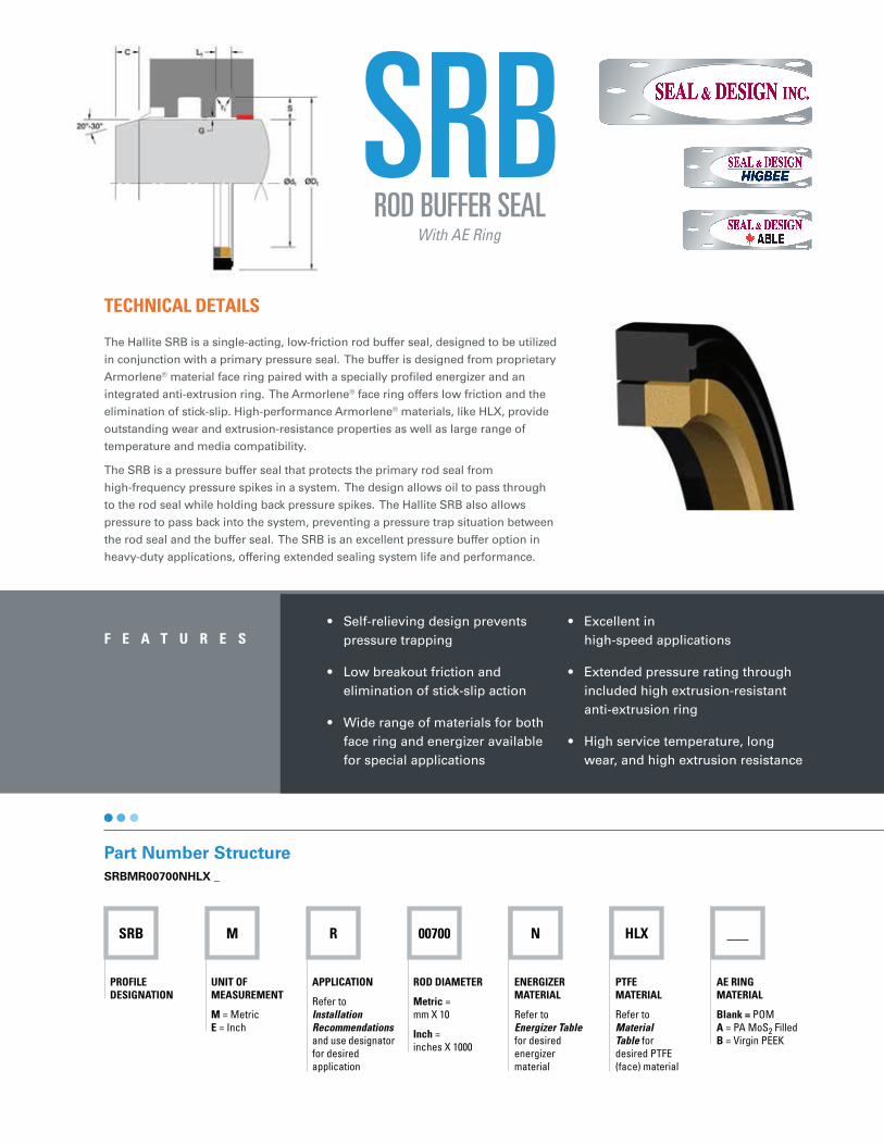
SRB M R 00700 N HLX ___
PROFILE DESIGNATION
UNIT OF MEASUREMENT
M = Metric
E = Inch
APPLICATION
Refer to
Installation
Recommendations
and use designator
for desired
application
ROD DIAMETER
Metric =
mm X 10
Inch =
inches X 1000
ENERGIZER MATERIAL
Refer to
Energizer Table
for desired
energizer
material
PTFE MATERIAL
Refer to
Material
Table for
desired PTFE
(face) material
AE RING MATERIAL
Blank = POM
A = PA MoS2 Filled
B = Virgin PEEK
SRB
• Self-relieving design prevents
pressure trapping
• Low breakout friction and
elimination of stick-slip action
• Wide range of materials for both
face ring and energizer available
for special applications
• Excellent in
high-speed applications
• Extended pressure rating through
included high extrusion-resistant
anti-extrusion ring
• High service temperature, long
wear, and high extrusion resistance
F E A T U R E S
TECHNICAL DETAILS
The Hallite SRB is a single-acting, low-friction rod buffer seal, designed to be utilized
in conjunction with a primary pressure seal. The buffer is designed from proprietary
Armorlene® material face ring paired with a specially profiled energizer and an
integrated anti-extrusion ring. The Armorlene® face ring offers low friction and the
elimination of stick-slip. High-performance Armorlene® materials, like HLX, provide
outstanding wear and extrusion-resistance properties as well as large range of
temperature and media compatibility.
The SRB is a pressure buffer seal that protects the primary rod seal from
high-frequency pressure spikes in a system. The design allows oil to pass through
to the rod seal while holding back pressure spikes. The Hallite SRB also allows
pressure to pass back into the system, preventing a pressure trap situation between
the rod seal and the buffer seal. The SRB is an excellent pressure buffer option in
heavy-duty applications, offering extended sealing system life and performance.
Part Number Structure
SRBMR00700NHLX _
ROD BUFFER SEALWith AE Ring
SR
B
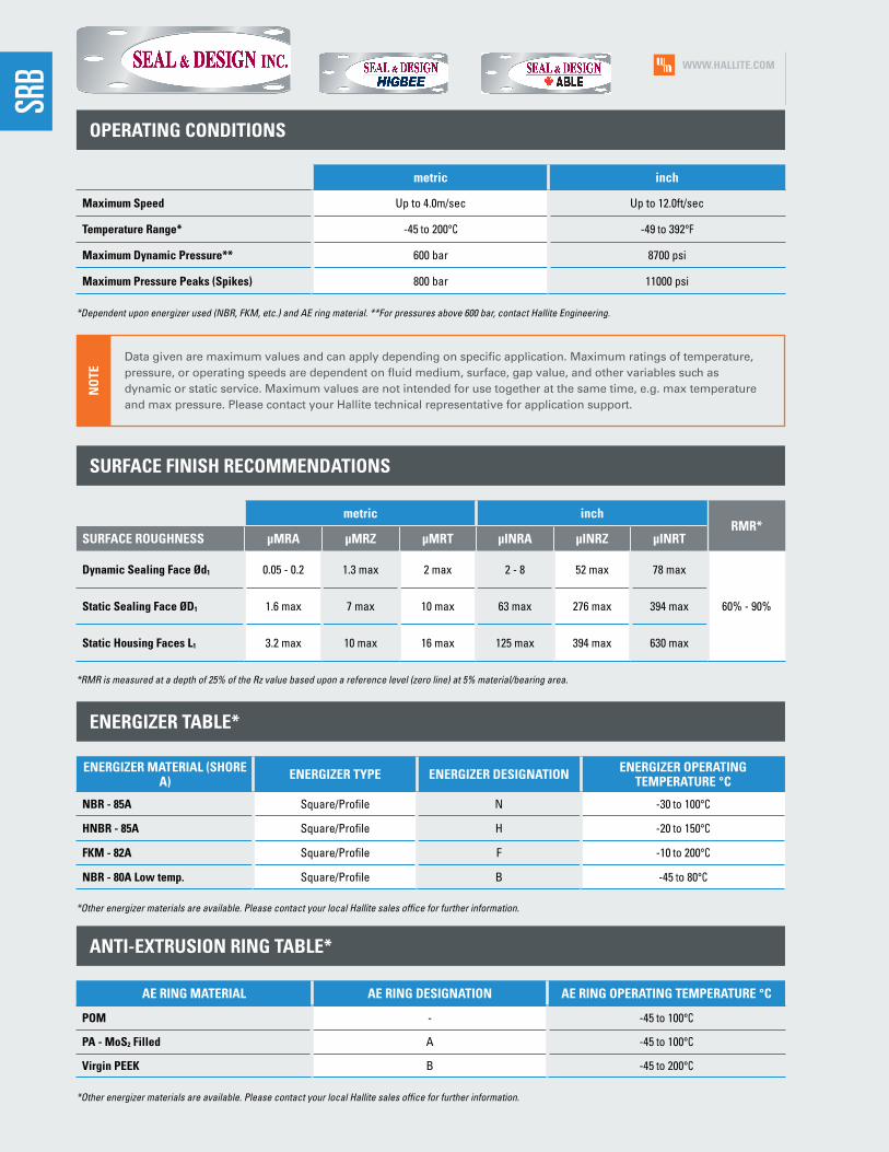
OPERATING CONDITIONS
*Dependent upon energizer used (NBR, FKM, etc.) and AE ring material. **For pressures above 600 bar, contact Hallite Engineering.
metric inch
Maximum Speed Up to 4.0m/sec Up to 12.0ft/sec
Temperature Range* -45 to 200°C -49 to 392°F
Maximum Dynamic Pressure** 600 bar 8700 psi
Maximum Pressure Peaks (Spikes) 800 bar 11000 psi
SURFACE FINISH RECOMMENDATIONS
metric inchRMR*
SURFACE ROUGHNESS µMRA µMRZ µMRT µINRA µINRZ µINRT
Dynamic Sealing Face Ød1 0.05 - 0.2 1.3 max 2 max 2 - 8 52 max 78 max
60% - 90%Static Sealing Face ØD1 1.6 max 7 max 10 max 63 max 276 max 394 max
Static Housing Faces L1 3.2 max 10 max 16 max 125 max 394 max 630 max
*RMR is measured at a depth of 25% of the Rz value based upon a reference level (zero line) at 5% material/bearing area.
ANTI-EXTRUSION RING TABLE*
AE RING MATERIAL AE RING DESIGNATION AE RING OPERATING TEMPERATURE °C
POM - -45 to 100°C
PA - MoS2 Filled A -45 to 100°C
Virgin PEEK B -45 to 200°C
*Other energizer materials are available. Please contact your local Hallite sales office for further information.
ENERGIZER TABLE*
*Other energizer materials are available. Please contact your local Hallite sales office for further information.
ENERGIZER MATERIAL (SHORE A)
ENERGIZER TYPE ENERGIZER DESIGNATIONENERGIZER OPERATING
TEMPERATURE °C
NBR - 85A Square/Profile N -30 to 100°C
HNBR - 85A Square/Profile H -20 to 150°C
FKM - 82A Square/Profile F -10 to 200°C
NBR - 80A Low temp. Square/Profile B -45 to 80°C
Data given are maximum values and can apply depending on specific application. Maximum ratings of temperature,
pressure, or operating speeds are dependent on fluid medium, surface, gap value, and other variables such as
dynamic or static service. Maximum values are not intended for use together at the same time, e.g. max temperature
and max pressure. Please contact your Hallite technical representative for application support.
NO
TE
WWW.HALLITE.COM

MATERIALS
MATERIAL FEATURES AND APPLICATIONS
FILL
ER
MA
TE
RIA
L D
ES
IGN
AT
OR
CO
LOR
TE
MP
ER
AT
UR
E
RA
NG
E°C
TE
MP
ER
AT
UR
E
RA
NG
E°F
MA
XIM
UM
DY
NA
MIC
P
RE
SS
UR
E -
BA
R
MA
XIM
UM
DY
NA
MIC
P
RE
SS
UR
E -
PS
I
ARMORLENE® HLX• Standard material for hydraulic applications• High compressive strength• Excellent extrusion resistance• Extended wear resistance
Special Bronze
CompoundHLX Gold -73 to 288°C -100 to 550°F 600 bar 8700 psi
ARMORLENE® HLA• Excellent in all hydraulic fluids• Excellent wear resistance• Excellent low-friction properties• Good extrusion resistance
Special Mineral
Compound HLA Gray -73 to 260°C -100 to 500°F 600 bar 8700 psi
ARMORLENE® HCF• Excellent in lubricating and non-lubricating
hydraulic fluids (includes water) w/o zinc content
• Not recommended for gas sealing applications
• Not recommended for electrical conductive fluids
Carbon Fiber Filled
HCFGray/ Black
-73 to 260°C -100 to 500°F 250 bar 3625 psi
ARMORLENE® 713• High compressive strength• Excellent extrusion resistance• Excellent wear properties
60% Bronze Content
713 Bronze -73 to 288°C -100 to 550°F 600 bar 8700 psi
For other material options consult the Master Materials Index at the front of the catalog. If you do not find the material that you require, please contact your local Hallite
sales office.
WWW.HALLITE.COM
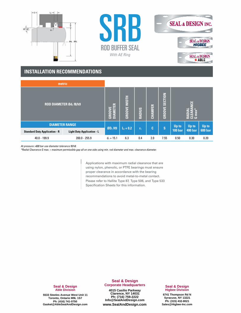
INSTALLATION RECOMMENDATIONS
metric
ROD DIAMETER Ød1 f8/h9
GR
OO
VE
D
IAM
ET
ER
GR
OO
VE
WID
TH
RA
DIU
S
CH
AM
FER
GR
OO
VE
SE
CT
ION
RA
DIA
L C
LEA
RA
NC
E
G m
ax
*
DIAMETER RANGE ØD1 H9 L1 + 0.2 r1 C S
Up to 100 bar
Up to 400 bar
Up to 600 barStandard Duty Application - R Light Duty Application - L
40.0 - 199.9 200.0 - 255.9 d1 + 15.1 6.3 0.4 2.0 7.55 0.50 0.30 0.20
At pressure >600 bar use diameter tolerance f8/h8.
*Radial Clearance G max. = maximum permissible gap all on one side using min. rod diameter and max. clearance diameter.
Applications with maximum radial clearance that are
using nylon, phenolic, or PTFE bearings must ensure
proper clearance in accordance with the bearing
recommendations to avoid metal-to-metal contact.
Please refer to Hallite Type 87, Type 506, and Type 533
Specification Sheets for this information.
SRBROD BUFFER SEAL
With AE Ring
Ph: (416) [email protected] www.SealAndDesign.com
Able Division
5533 Steeles Avenue West Unit 11Toronto, Ontario M9L 1S7
Ph: (315) [email protected]
Higbee Division6741 Thompson Rd NSyracuse, NY 13221Ph: (716) 759-2222
Corporate Headquarters4015 Casilio ParkwayClarence, NY 14031
Seal & DesignSeal & Design Seal & Design

PART NUMBER RANGE (METRIC)*
40.0 55.1 6.3 SRBMR00400****
45.0 60.1 6.3 SRBMR00450****
50.0 65.1 6.3 SRBMR00500****
55.0 70.1 6.3 SRBMR00550****
60.0 75.1 6.3 SRBMR00600****
65.0 80.1 6.3 SRBMR00650****
70.0 85.1 6.3 SRBMR00700****
75.0 90.1 6.3 SRBMR00750****
80.0 95.1 6.3 SRBMR00800****
85.0 100.1 6.3 SRBMR00850****
90.0 105.1 6.3 SRBMR00900****
95.0 110.1 6.3 SRBMR00950****
100.0 115.1 6.3 SRBMR01000****
105.0 120.1 6.3 SRBMR01050****
110.0 125.1 6.3 SRBMR01100****
115.0 130.1 6.3 SRBMR01150****
120.0 135.1 6.3 SRBMR01200****
125.0 140.1 6.3 SRBMR01250****
130.0 145.1 6.3 SRBMR01300****
135.0 150.1 6.3 SRBMR01350****
140.0 155.1 6.3 SRBMR01400****
145.0 160.1 6.3 SRBMR01450****
150.0 165.1 6.3 SRBMR01500****
155.0 170.1 6.3 SRBMR01550****
160.0 175.1 6.3 SRBMR01600****
165.0 180.1 6.3 SRBMR01650****
170.0 185.1 6.3 SRBMR01700****
175.0 190.1 6.3 SRBMR01750****
180.0 195.1 6.3 SRBMR01800****
185.0 200.1 6.3 SRBMR01850****
190.0 205.1 6.3 SRBMR01900****
195.0 210.1 6.3 SRBMR01950****
200.0 215.1 6.3 SRBML02000****
205.0 220.1 6.3 SRBML02050****
210.0 225.1 6.3 SRBML02100****
215.0 230.1 6.3 SRBML02150****
220.0 235.1 6.3 SRBML02200****
225.0 240.1 6.3 SRBML02250****
230.0 245.1 6.3 SRBML02300****
235.0 250.1 6.3 SRBML02350****
240.0 255.1 6.3 SRBML02400****
245.0 260.1 6.3 SRBML02450****
250.0 265.1 6.3 SRBML02500****
metric
Ød
1
ØD
1
L 1
PA
RT
NU
MB
ER
Tol. f8/h9 Tol. H9 Tol. +0.2 - 0
metric
Ød
1
ØD
1
L 1
PA
RT
NU
MB
ER
Tol. f8/h9 Tol. H9 Tol. +0.2 - 0
SRBROD BUFFER SEAL
With AE Ring
*Please contact Hallite for custom sizes, material selection, or seal design.