Embed Size (px)
Citation preview

HA 20-E
HALFEN DEHA SOCKET ANCHOR SYSTEMTechnical Product Information

Under the Leviat brand, we are uniting the
expertise, skills and resources of HALFEN and its
sister companies to create a world leader in fixing,
connecting and anchoring technology.
The products you know and trust, including the
HALFEN DEHA Socket Anchor System, will remain
an integral part of Leviat’s comprehensive brand
and product portfolio. As Leviat, we can offer
you an extended range of specialist products
and services, greater technical expertise, a larger
and more agile supply chain and better, faster
innovation.
By bringing together CRH’s construction
accessories family as one global organisation,
we are better equipped to meet the needs of our
customers, and the demands of construction
projects, of any scale, anywhere in the world.
This is an exciting change. Join us on our journey.
Read more about Leviat at Leviat.com
Leviat is the new name of CRH’s construction accessories companies worldwide.
We are one team. We are Leviat.

people worldwidecountries
sales in
Our product brands include:
locations300030+60
Imagine. Model. Make. Leviat.com

HD
CE
© 2020 · HA 20-E · www.halfen.com2
HALFEN DEHA SOCKET ANCHOR SYSTEMSCertified quality — Connected to safety.
Dependability
Specially tempered steel guarantees extensive elastic and plastic properties. The required unique steel compositions to achieve these product characteristics are specified by us. Numerous tests and many years of experience guarantee the best possible results and maximum reliability in all applications.
The special composition of the steel ensures constant identical characteristics (temperature independent). The steel used by us exceeds the requirement of DIN EN 10025.
By specifying products, materials and continual raw material and product monitoring, and testing by renown independent bodies and universities, our customers can be sure that the quality and properties of all our lifting anchors remain consistent.
High ductility — High performance even in extreme situations
Toughness at subzero temperatures — Same material characteristics irrespective of weather conditions
Quality control — for reliable application
The HALFEN DEHA Socket anchorsystem meets the requirements of European Machinery Directive (MD) 2006/42/EC.The directive defines the required steel-load-bearing properties for anchor systems used for lifting.
In order to guarantee the resistance of the cast-in anchors required for the safe application of lifting anchor systems, our lifting anchors and lifting anchor systems are also subject to the requirements of the guideline VDI/BV-BS 6205.
This guideline entitled “Lifting inserts and Lifting insert Systems for Precast Concrete Elements” represents the recognized state of the art in this field.
By complying with the requirements of this guideline we ensure a constant, high level of safety for the use of our lifting anchors and lifting anchor systems.
All our lifting anchor systems are CE marked. This confirms conformity with MD 2006/42/EC in connection with the VDI/BV-BS 6205.
Machinery directive MD 2006/42/EC
VDI/BV-BS 6205
Precast element
Lifting anchor system + Lifting anchor
Lifting link
Our lifting anchors and lifting anchor systems are subject to a system of regular internal and external monitoring, which are certified by the MPA NRW.
We guarantee consistent high quality and maximum safety for you, your company and your employees.
This catalogue includes the installation and application instruction as defined in VDI/BV-BS 6205.
MD 2006/42/ECMD 2006/42/ECVDI/BV-BS 6205VDI/BV-BS 6205
of this guideline we ensure a constant, high level of safety for the use of our lifting anchors and lifting anchorsystems.

DEHA 04
SRd 20
DEHA Hülsenanker
Combi-Anker Hülsen-Stabanker Hülsen-Plattenanker
Verwendung:Zum Transport von Stahlbetonfertigteilen unterschiedlichster Abmessungen.
Zum Transport besonders dünnen Betonfertig-teilen z.B. Garagenwände.
Zum Transport von großflächigen, dünnen Betonfertigteilen, die senkrecht zu ihrer Hauptausdehnung gehoben werden sollen (Platten und Schalen).
Lastgruppe 0,5 - 12,5 0,5 - 12,5 0,5 - 4,0
Hebehülse Kronenanker Kurzanker
Verwendung:
Zum Transport dünner Fertigteilwänden oder bei geringer Betonfestigkeit. Krafteinleitung erfolgt mit der durch den Anker geführten Zulagebewehrung.
Zum Transport von flächigen Fertigteilen wie Deckenplatten und dergleichen.
Zum Transport von großflächigen, dünnen Betonfertigteilen (Platten und Schalen).
Lastgruppe 0,5 - 4,0 0,5 - 4,0 0,5
DEHA Lastaufnahmemittel
Ankerschlaufe Perfektkopf Combikopf Adapter mit Universalkopf-Kupplung
Verwendung:
Die Standardlösung zum Transport von Fertigteilen in Verbindung mit eingebauten Hülsenankern.
Zum Transport von Fertigteilen in Verbindung mit eingebauten Hülsenankern. Besonders geeignet bei Schrägzug.
Zum Transport von Fertigteilen in Verbindung mit eingebauten Hül-senankern. Besonders geeignet für Schräg- und Querzug.
Der Adapter ermöglicht die Kom-bination zwischen Schnellkupplung und Hülsenanker-System. Zum Transportieren wird die DEHA Universalkopf-Kupplung in den Adapter eingehängt.
Lastgruppe 0,5 - 12,5 0,5 - 12,5 0,5 - 12,5 M/Rd 12 -52
DEHA 04
SRd 16
DEHA 04
SRd 16
© 2009 HALFEN · HA 09 · www.halfen.de
DEHA HÜLSENANKER - SYSTEM
System - Übers icht
4
© 2020 · HA 20-E · www.halfen.com 3
CONTENT System Overview
HALFEN DEHA Socket anchor 4HALFEN DEHA Load lifting devices 4HALFEN DEHA Socket anchor accessories 5Product range anchors/accessories 6-7Product range lifting links, load class — colour codes 8
Installation and application instructionsSafety 9Load lifting devices — application 10Selection — lifting anchor system 11
Lifting anchors HA Combi anchor 14HA Rod anchor 17HA Plate anchor 20HA Crown anchor and HA Short anchor 21HA Plain anchor 22
Accessories General information 23HALFEN DEHA Identification cap 23Nailing plate and accessories 24HALFEN DEHA Recess fillers, moulds 27Assembly pin, sealing plates, sealing plugs 32
Load lifting devices General information, HA Lifting loop 28HALFEN DEHA Perfect head, inspection of cable loops 29HALFEN DEHA Rotary head lifting clutch 30HALFEN DEHA Adapter, HALFEN DEHA Universal head clutch 32
Installation Installation — sealing plates 34Installation — HD Lifting anchor system 35
HALFEN products/Technical supportLifting loops, accident recovery unit 36-38Contact 41

HALFEN DEHA Lifting links
HA Lifting loop Perfect lifting head Rotary head Adapter for the universal lifting head
Application
The standard solution for lifting precast elements with cast-in socket anchors
Used to lift precast elements with cast-in socket anchors.Especially suitable for diagonal loading
Suitable for diagonal and shear loading. The rotatable head allows the clutch to be screwed in to the HA Anchor without turning the head
This adapter allows the socket anchor system to be used with the HALFEN DEHA Spherical-head lifting system. The HALFEN DEHA Universal head clutch can then be used for lifting
Load class 0,5 – 12,5 0,5 – 12,5 0,5 – 12,5 M/Rd 12 – 52
6311 6377 6367 6366
HALFEN DEHA Anchors
HA Combi anchor HA Rod anchor HA Plate anchor
Application
Used to lift a wide range of different format precast concrete elements
Used to lift especially thin precast elements; for example; precast garage walls
Used to lift large, thin precast slab elements that are lifted perpendicular to their main surface (slabs and shells)
Load class 0,5 – 12,5 0,5 – 12,5 0,5 – 6,3
HA Plain socket HA Crown anchor HA Short anchor
Application
Used to lift thin precast walls or for use in low-strength concrete. Load transfer into the concrete is with hanger reinforcement inserted through the anchor hole
Used to lift precast slab elements; floor slabs and similar
Used to lift large precast thin slab elements (slabs and shells)
Load class 0,5 – 6,3 0,5 0,5
6372 6380 6308
6351 6319 6346
DEHA 04
SRd 20
© 2020 · HA 20-E · www.halfen.com4
HALFEN DEHA SOCKET ANCHOR SYSTEMSystem Overview

Nailing plate (10 mm) for combi anchors, steel core + replacement ring
Combi nailing plate (20 mm), steel core + replacement ring
Identification cap
6510 6520 6357
Material Ring: plastic / Thread: steel Ring: plastic / Thread: steel Plastic
Application
Used to fix the socket anchor to the form-work when using the lifting loop (6311), HALFEN DEHA Combi lifting head (6356), HALFEN DEHA Perfect lifting head (6313, 6377) and the adapter (6366) for the Universal head lifting link (6102)
Used to fix the socket anchor to formwork when using the lifting loop (6311), HALFEN DEHA Combi lifting head (6356), HALFEN DEHA Perfect lifting head (6313, 6377).
Identifies the cast-in socket anchor. Also used to secure any additional reinforcement
M/Rd 12– 52 12 – 52 Load class 0,5 – 12,5
Sealing plugs Sealing plates Mould for the combi nailing plate Retaining bolt S1
6359 6315 6513 6329 TPA-S1
Material Plastic Plastic Rubber Steel
Application
Plugs protect the threads against dirt, soil etc.
Used to seal the anchor sockets as protection against dirt etc.; also for use in fair-faced concrete. Suitable for: 6358, 6369, 6365, 6510
Used to make concrete recess fillers The bolt secures the steel nailing plate to the formwork
M/Rd 12 – 52 12, 16, 20, 24 All load classes All load classes
HALFEN DEHA Anchor accessories
Nailing plate — combi anchors Nailing plate — steel Nailing plate — steel core + magnet
6358 6369 6365
Material Plastic Steel Steel
ApplicationNailing plates are used to fix the socket anchor to formwork; used for the lifting loop (6311), HALFEN DEHA Combi lifting head (6356), HALFEN DEHA Perfect lifting head (6313,6377),
and the adapter (6366) for the Universal head lifting link (6102).
M/Rd 12– 52 12– 52 (except 14, 18) 12– 52 (except 14, 18)
© 2020 · HA 20-E · www.halfen.com 5
HALFEN DEHA SOCKET ANCHOR SYSTEMSystem Overview

HA Combi anchor
Load class
Article name
Order no.0740.010-
zinc
pla
ted
0,56351-0,5-100 00002
6351-0,5-150 00003
0,8
6351-0,8-075 00007
6351-0,8-105 00005
6351-0,8-155 00006
1,26351-1,2-130 00009
6351-1,2-175 00010
1,6
6351-1,6-090 00015
6351-1,6-150 00013
6351-1,6-225 00014
2,0
6351-2,0-100 00016
6351-2,0-183 00017
6351-2,0-250 00018
2,5
6351-2,5-115 00020
6351-2,5-200 00021
6351-2,5-275 00022
4,0
6351-4,0-144 00025
6351-4,0-275 00026
6351-4,0-345 00027
6,3 6351-6,3-334 00029
8,06351-8,0-385 00031
6351-8,0-500 00032
12,5 6351-12,5-550 00033
Load class Article nameOrder no.0740.010-
stai
nles
s st
eel A
4 so
cket
0,5 6351-0,5-100 A4 00036
0,86351-0,8-075 A4 00050
6351-0,8-105 A4 00038
1,26351-1,2-075 A4 00039
6351-1,2-130 A4 00040
1,66351-1,6-090 A4 00051
6351-1,6-150 A4 00041
2,0 6351-2,0-183 A4 00042
2,5 6351-2,5-200 A4 00044
4,0 6351-4,0-275 A4 00046
6,3 6351-6,3-334 A4 00047
8,0 6351-8,0-385 A4 00048
12,5 6351-12,5-550 A4 00049
Base: steel, mill-finish
HA Rod anchor
Load class
Article nameOrder no.0740.030-
zinc
pla
ted
0,5 6319-0,5-190 00001
0,8 6319-0,8-230 00003
1,2 6319-1,2-270 00004
1,6 6319-1,6-350 00006
2,0 6319-2,0-350 00007
2,5
6319-2,5-400 00010
6319-2,5-450 00011
6319-2,5-720 00018
4,0 6319-4,0-540 00012
6,3 6319-6,3-670 0013
8,0 6319-8,0-780 00014
12,56319-12,5-1100 00015
6319-12,5-1290 00016
Load class
Stainless steel A4 socket
Article nameOrder no.0740.030-
0,5 – 12,5 on request
Bar: B500B (BSt 500 S)
HA Plate anchor
Load class
Article nameOrder no.0740.050-
zinc
pla
ted
0,5 6346-12 00001
0,8 6346-14 00002
1,2 6346-16 00003
1,6 6346-18 00004
2,0 6346-20 00005
2,5 6346-24 00006
4,0 6346-30 00007
6,3 6346-36 00015
Load class Article nameOrder no.0740.050-
stai
nles
s st
eel A
4
0,5 6346-12 A4 00008
0,8 6346-14 A4 00009
1,2 6346-16 A4 00010
1,6 6346-18 A4 00011
2,0 6346-20 A4 00012
2,5 6346-24 A4 00013
4,0 6346-30 A4 00014
6,3 6346-36 A4 00016
HA Crown anchor
Load class
Article nameOrder no.0740.020-
zinc
pla
ted
0,5 6380-0,5-60 00001
Not available in stainless steel!
HA Plain anchor
Load class
Article nameOrder no.0740.040-
zinc
pla
ted
0,5 6372-12 00001
0,8 6372-14 00002
1,2 6372-16 00003
1,6 6372-18 00004
2,0 6372-20 00005
2,5 6372-24 00006
4,0 6372-30 00007
6,3 6372-36 00008
Load class
Article nameOrder no.0740.040-
stai
nles
s st
eel A
4
0,5 6372-12 A4 00009
0,8 6372-14 A4 00016
1,2 6372-16 A4 00011
2,0 6372-20 A4 00013
2,5 6372-24 A4 00014
4,0 6372-30 A4 00015
6,3 6372-36 A4 00017
HA Short anchor
Load class zinc plated
Article nameOrder no.0740.060-
0,5 6308-0,5-050 00001
Load classStainless steel A4
Article nameOrder no.0740.060-
0,5 6308-0,5-050 A4 00014
© 2020 · HA 20-E · www.halfen.com6
HALFEN DEHA SOCKET ANCHOR SYSTEMProduct Range HALFEN DEHA Socket Anchors

Socket anchor accessories
Loadclass
Combi nailing plate,plastic
Identification cap, plastic
Nailing plate,steel
Nailing plate,with magnet
Nailing plate, steel with thread reducer,
preassembled
Articlename
Order no.0741.040-
Articlename
Order no.0741.110-
Articlename
Order no.0741.190-
Articlename
Order no.0741.180-
Articlename
Order no.0741.190-
0,5 6358-12 00001 6357-12 00001 6369-12 00001 6365-12 00001 - -
0,8 6358-14 00002 6357-14 00002 - - - - - -
1,2 6358-16 00003 6357-16 00003 6369-16 00002 6365-16 00002 6369-16 00102
1,6 6358-18 00004 6357-18 00004 - - - - -
2,0 6358-20 00005 6357-20 00005 6369-20 00003 6365-20 00003 6369-20 00103
2,5 6358-24 00006 6357-24 00006 6369-24 00004 6365-24 00004 6369-24 00104
4,0 6358-30 00007 6357-30 00007 6369-30 00005 6365-30 00005 6369-30 00105
6,3 6358-36 00008 6357-36 00008 6369-36 00006 6365-36 00006 - -
8,0 6358-42 00009 6357-42 00009 6369-42 00007 6365-42 00007 - -
12,5 6358-52 00010 6357-52 00010 6369-52 00008 6365-52 00008 - -
Socket anchor accessories
Loadclass
Combi nailing plate,steel core
Replacement ring for 6510
Nailing plate, steel core
Replacement ring for 6520
Retaining bolt Mould for thecombi nailing plate
Articlename
Order no.0741.080-
Articlename
Order no.0741.090-
Articlename
Order no.0741.210-
Articlename
Order no.0741.230-
Articlename
Order no.0073.060-
Articlename
Order no.0741.290-
0,5 6510-12 00101 6512-12 00001 6520-12 00101 6522-12 00001S1-08 00001
6329-12-16 000010,8 6510-14 00002 6512-14 00002 6520-14 00002 6522-14 000021,2 6510-16 00103 6512-16 00003 6520-16 00103 6522-16 00003
S1-12 00002
1,6 6510-18 00004 6512-18 00004 6520-18 00004 6522-18 000046329-18-24 000022,0 6510-20 00105 6512-20 00005 6520-20 00105 6522-20 00005
2,5 6510-24 00106 6512-24 00006 6520-24 00106 6522-24 000064,0 6510-30 00107 6512-30 00007 6520-30 00107 6522-30 00007
6329-30-36 000036,3 6510-36 00108 6512-36 00008 6520-36 00108 6522-36 000088,0 6510-42 00109 6512-42 00009 6520-42 00109 6522-42 00009
S1-16 00003 6329-42-52 0000412,5 6510-52 00110 6512-52 00010 6520-52 00110 6522-52 00010
Socket anchor accessories
Loadclass
Sealing plate Sealing plug Sealing plug HD Assembly pin Sealing plate, rubber(yellow)
Tool for nailing plates, steel
Articlename
Order no.0741.280-
Articlename
Order no.0741.120-
Articlename
Order no.0741.130-
Articlename
Order no.0741.300-
Articlename
Order no.0741.330-
Articlename
Order no.0741.350-
0,5 6313-12 00001 6359-12 00001 6315-12 00001
6330-Rd 12–30(except:Rd 14, Rd 18)
00001
6334-Rd 12–16
000016337-
Rd 12–16000010,8 - - 6359-14 00002 6315-14 00002
1,2 6313-16 00002 6359-16 00003 6315-16 000031,6 - - 6359-18 00004 6315-18 00004
6334-Rd 18–24
00002
6337-Rd 20–52
00002
2,0 6313-20 00003 6359-20 00005 6315-20 000052,5 6313-24 00004 6359-24 00006 6315-24 000064,0 - - 6359-30 00007 6315-30 00007 6334-
Rd 30–36000036,3 - - 6359-36 00008 6315-36 00008
8,0 - - 6359-42 00009 6315-42 00009 - -- -
12,5 - - 6359-52 00010 6315-52 00010 - -
h =10 mm h =10 mm h =20 mm h =20 mm
20
© 2020 · HA 20-E · www.halfen.com 7
HALFEN DEHA SOCKET ANCHOR SYSTEMProduct Range Accessories

pink 0,5 12
yellow 0,8 14
white 1,2 16
black 1,6 18
light green 2,0 20
light blue 2,5 24
lilac 4,0 30
yellow 6,3 36
light brown 8,0 42
dark grey 12,5 52
red 1,3 12
− − −
light grey 2,5 16
− − −
green 4,0 20
blue 5,0 24
violet 7,5 30
orange 10,0 36
brown 12,5 42
black 15,0 52
Standard load class Increased load class (see HALFEN HD Anchor catalogue)
Colour Load class Thread M/Rd Colour Load class Thread M/Rd
Lifting devices
Load class
HA Lifting loop Perfect head Adapter Universal head lifting link Rotary head lifting clutch
Article name
Order no.0742.040-
Article name
Order no.0742.
Article name
Order no.0742.
Article name
Order no.0738.010-
Article name
Order no.0742.230-
0,5 6311-12 00001 6377-12 170-00001 6366-12 140-00001 6102-1,0/1,3 00001 6367-12 00001
0,8 6311-14 00002 6313-14 060-00002 6303-14 090-00002
6102-1,5/2,5 00002
– –
1,2 6311-16 00003 6377-16 170-00002 6366-16 140-00002 6367-16 00002
1,6 6311-18 00004 6313-18 060-00004 6303-18 090-00004 – –
2,0 6311-20 00005 6377-20 170-00003 6366-20 140-000036102-3,0/5,0 00003
6367-20 00003
2,5 6311-24 00006 6377-24 170-00004 6366-24 140-00004 6367-24 00004
4,0 6311-30 00007 6377-30 170-00005 6366-30 140-000056102-6/10 00004
6367-30 00005
6,3 6311-36 00008 6377-36 170-00006 6366-36 140-00006 6367-36 00006
8,0 6311-42 00009 6377-42 170-00007 6366-42 140-000076102-12/20 00005
6367-42 00007
12,5 6311-52 00010 6377-52 170-00008 6366-52 140-00008 6367-52 00008
DEHA 04
SRd 20
© 2020 · HA 20-E · www.halfen.com8
HALFEN DEHA SOCKET ANCHOR SYSTEMProduct Range Lifting Links/Colour Codes
Each load class is defined with a specific, fixed designation. There are two load classes: The standard load classes and the increased load classes.
The standard load classes are identified with bright colours. The increased load classes are identified with dark colours.
Load classes — colour codes

Safety against failure
Steel failure of anchors: = 3.0
Concrete failure*: = 2.5
Breakage of lifting link: = 4.0
© 2020 · HA 20-E · www.halfen.com 9
HALFEN DEHA SOCKET ANCHOR SYSTEMInstallation and Application
All lifting anchors and attachment links must be clearly labelled and easily identified by the user. According to the VDI/BV-BS 6205 the identification markings should remain visible after installation.
The plant or site manager must ensure that the operator has read and un-derstood the installation and assembly instructions for this system.
The HALFEN DEHA Socket anchor sys-tem must be installed according to the following technical instructions.
Safety regulations
Sealing
Quality control
Installation and application
Anchor selection
Lifting anchors - stainless steel
Identification
The lifting anchor system consists of the permanently cast-in lifting anchor and the temporarily connected lifting equipment.
The basic principles for calculating and using lifting anchors are described in the guideline VDI/BV-BS 6205.
The regulations require the following safety factors:
Article name, example: 6351
Thread size
DHR = manufacturer identification
Colour identifies the load class
Type S = for lifting with:• rotary head lifting clutch• perfect head• lifting loop • adapter and universal head lifting link
CE marking
on the socket
Identification
* A safety factor of = 2.1 can be assumed for lifting anchors installed in a continuous-ly supervised factory environment.
To ensure safe application of the HALFEN DEHA Anchor
system, these installation and ap-plication instructions must always be available at the place of use.
on theidentification cap
Repeated use of a lifting anchor is not permitted. Multiple lifting within one transport-chain from production to final installation of an element is not regarded as repeated use and is therefore allowed. In accordance with approval no. Z-30.3-6 the socket sleeves for lifting anchors for permanent use (in crane ballast, stop log gates etc.) must be made of stainless steel.
Lifting anchors that have been incorrectly installed or show signs of damage, for example: damage from corrosion or other visible deformation are not to be used for lifting.
The installation and application instruc-tions for each lifting system must be readily available on site, in the precast plant or on the construction site.
Maximum load capacities, edge distances and installation values can be found in the respective tables. Irrespective of the selected anchor type (selected according to the load acting on the anchor) the following factors must be taken into account for calculation:
Ensure sufficient pitching reinforcement if slabs are cast in the horizontal and subsequently lifted upright without a tilting-table.
Sealant to prevent corrosion when using stainless steel sleeves
All lifting anchors and systems are quality controlled internally as well as in accordance with DIN EN ISO 9001.
weight of the precast element
number of anchors
anchor layout
number of load bearing anchors
spread angle in the hoist
diagonal load properties of the anchor
dynamic loads
adhesion to the formwork
≤45°
≤45° ≤45°
≤45°
≤45°
≤45°
≤45°
≤45°
≤ 90°
90°
© 2020 · HA 20-E · www.halfen.com10
HALFEN DEHA SOCKET ANCHOR SYSTEMInstallation and Application
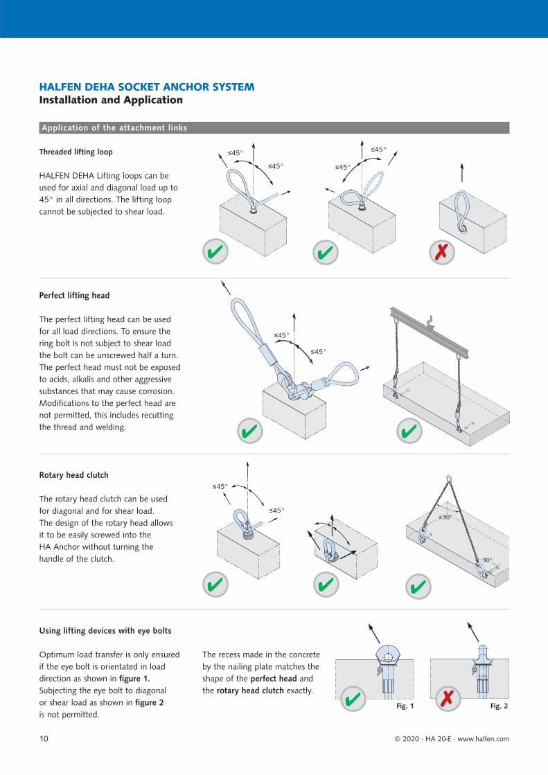
The rotary head clutch can be used for diagonal and for shear load. The design of the rotary head allows it to be easily screwed into the HA Anchor without turning the handle of the clutch.
Rotary head clutch
Perfect lifting head
The perfect lifting head can be used for all load directions. To ensure the ring bolt is not subject to shear load the bolt can be unscrewed half a turn. The perfect head must not be exposed to acids, alkalis and other aggressive substances that may cause corrosion. Modifications to the perfect head are not permitted, this includes recutting the thread and welding.
Using lifting devices with eye bolts
Optimum load transfer is only ensured if the eye bolt is orientated in load direction as shown in figure 1.Subjecting the eye bolt to diagonal or shear load as shown in figure 2is not permitted.
The recess made in the concrete by the nailing plate matches the shape of the perfect head and the rotary head clutch exactly.
HALFEN DEHA Lifting loops can be used for axial and diagonal load up to 45° in all directions. The lifting loop cannot be subjected to shear load.
Threaded lifting loop
Fig. 1 Fig. 2
Application of the attachment links

Spread angle factors
Cable angle Spread angle Factor
z
0° – 1.00
7.5° 15.0° 1.01
15.0° 30.0° 1.04
22.5° 45.0° 1.08
30.0° 60.0° 1.16
37.5° 75.0° 1.26
45.0° 90.0° 1.41
52.5° 105.0° 1.64
60.0° 120.0° 2.00
Dynamic-factors dyn*
Lifting unitShock factors
dyn*
Stationary crane, swing-boom crane, rail crane
1.3
Lifting and moving on level terrain
2.5
Lifting and moving on uneven terrain ≥ 4.0
© 2020 · HA 20-E · www.halfen.com 11
HALFEN DEHA SOCKET ANCHOR SYSTEMInstallation and Application
The load capacity of the system depends on:
concrete compression strength fci at time of lift (cube-test 15 × 15 × 15 cm)
embedment depth of the anchor
edge and axial anchor-spacings
load direction
reinforcement layout
The effect of dynamic loading depends largely on the type of hoist selected between the crane and the load lifting head. Hoisting cables made of steel or synthetic fibre have a damping effect. With increasing cable length the damping effect is also increased; however, short chains have an adverse effect. The forces acting on the lifting anchor should be calculated using the dynamic factors dyn.
If other values from reliable tests or through proven experience are avail-able for ψdyn, then these may be used for calculation.
With lifting situations other than listed the factor dyn is determined through tests or values based on previousexperience.
FZ = tension force on the anchor [kN]
FG = weight of precast element [kN](acc. to DIN EN 1991-1-1 specific weight of = 25 kN/m3)
Af = contact surface between the concrete and formwork [m2]
n = number of load bearing anchors
z = diagonal load factor, z = 1/cos
dyn = dynamic factor
qadh = base value for formwork adhesion
Fadh = effective load caused by formwork adhesion [kN]
Abbreviations:
In general the tensile force FZ acting on the anchor is determined using the following equation:
Removing from the formworkFZ = FG × z × / n orFZ = (FG + qadh × Af) × z / n
LiftingFZ = FG × z × dyn / n
The number of anchors determines the type of hoist that needs to be used. A hoist with more than two cables is statically indeterminate if the anchors are aligned along a single axis. Hoists with more than three cables are deemed statically indeterminate if measures are not taken to ensure the load is distributed evenly amongst all anchors (for example; with a spreader beam).
30°=
45°
60°
90°β
F
FGT
120°
G
not allowable
FZ
= 0.
5
FZ
= 0.
5 = 0
.52
= 0
.54
=0.54
= 0
.58
= 0.58
= 0.7
= 0.7
= 1.0
= 1.0
= 0.52
GG
G
G
GG
G
GG
G
G
G
■ This spread angle is not permitted for cable spread!
Number of anchors
Total load on the anchor
Load capacities Dynamic forces
Load directions
Definition of load directons:
Axial loadThe lifting link acts in the longi-tudinal direction of the cast-in lifting anchor
Diagonal loadThe lifting link acts at an angle to the longitudinal direction directly in the element
Shear loadThe lifting link acts perpendicu-lar to the cast-in lifting anchor

Adhesion to the formwork
Lubricated steel formwork q ≥ 1 kN/m2
Varnished timber formwork q ≥ 2 kN/m2
Untreated formwork q ≥ 3 kN/m2
Increased adhesion to the formwork
- panel = 2
Ribbed panel = 3
Waffled panel = 4
A
© 2020 · HA 20-E · www.halfen.com12
HALFEN DEHA SOCKET ANCHOR SYSTEMInstallation and Application
Adhesion to the formwork should be minimised before lifting by removing as many parts of the formwork as possible.
F Z,a = F G × b / ( a + b )
F Z,b = F G × a / ( a + b )
Fadh = qadh × Af
Adhesion between the formwork and the concrete vary according to the type of formwork used.
The following values may be used as a guide:
The value (Fadh) for adhesion to the formwork is calculated with the following equation:
Surface of the prefabricated concrete element in contact with the formwork prior to lifting.
FG
Ftotal
FZ,a FZ,b
The centre of gravity of the load will always stabilise verticality under the crane hook. Load distribution in non-symmetrical installed anchors when using a spreader beam is calculated as follows:
Note: To avoid precast elements hanging at a slant when being moved the hook in the spreader beam should be directly above the centre of gravity. If lifting elements without a spreader beam then the lifting anchors should be installed symmetrically to the centre of gravity.
Use a wedge to carefully prise difficult to remove formwork from hardened concrete.Substantial load increase can also be
encountered when components are lifted parallel or near parallel to parts of the formwork. This applies to ribbed slabs and coffered ceiling slabs and can also apply to vertically cast columns and slabs.
Increased adhesion must be assummed for - panel and coffered ceiling slabs. A multiple of the dead weight is used to simplify calculation.
Adhesion to the formwork Anchor positioned asymmetrically
The load in each anchor is calculated using bar statics if the anchors are not installed symmetrically to the load’s centre of gravity.
Uneven loading of the anchor caused by non-symmetrical installed anchors in respect to the load’s centre of gravity:

≥ ez/2
≥ ez/2≥ ez
≥ ez/2
≥ ez/2
≥ ez/2≥ ez/2
≥ ez
≥ ez≥ ez
≥ ez≥ ez
≥ ez
© 2020 · HA 20-E · www.halfen.com 13
HALFEN DEHA SOCKET ANCHOR SYSTEMInstallation and Application
Axial load β: 0° to 10° Tilting 90°Diagonal load β: 10° to 60°
pulley
Positioning of anchors in walls
Assumed number of load bearing anchors: n = 2
Assumed number of load bearing anchors: n = 4
Assumed number of load bearing anchors: n = 4
Additional shear reinforcement can be omitted when using a tilting table and a load angle of γ < 15°.
Tensile loads at the anchors
Static system
2×er 2×er2×er
Not recommended for angles > 45°
Dimensions and installation values
Load classZinc plated Sleeve stainless steel A4
ThreadRd
l[mm]
e[mm]Article name
Order no.0740.010-
Article nameOrder no.0740.010-
0,56351-0,5-100 00002 6351-0,5-100 A4 00036
12100
316351-0,5-150 00003 - - 150
0,86351-0,8-075 00007 6351-0,8-075 A4 00050
1475
256351-0,8-105 00005 6351-0,8-105 A4 00038 1056351-0,8-155 00006 - - 155
1,2- - 6351-1,2-075 A4 00039
1675
366351-1,2-130 00009 6351-1,2-130 A4 00040 1306351-1,2-175 00010 - - 175
1,66351-1,6-090 00015 6351-1,6-090 A4 00051
18090
316351-1,6-150 00013 6351-1,6-150 A4 00041 1506351-1,6-225 00014 - - 225
2,06351-2,0-100 00016 - -
20100
426351-2,0-183 00017 6351-2,0-183 A4 00042 1836351-2,0-250 00018 - - 250
2,56351-2,5-115 00020 - -
24115
486351-2,5-200 00021 6351-2,5-200 A4 00044 2006351-2,5-275 00022 - - 275
4,06351-4,0-144 00025 - -
30144
586351-4,0-275 00026 6351-4,0-275 A4 00046 2756351-4,0-345 00027 - - 350
6,3 6351-6,3-334 00029 6351-6,3-334 A4 00047 36 334 66
8,06351-8,0-385 00031 6351-8,0-385 A4 00048
42385
756351-8,0-500 00032 - - 500
12,5 6351-12,5-550 00033 6351-12,5-550 A4 00049 52 550 89
Reinforcement and load capacity — axial load
Load classArticle name
Threadmin.
thickness2 × er
Main reinforcement
meshEdge reinforcement
Axial load up to 10°Load capacity [kN] at concrete strength fci
Anchor spacingez
Rd [mm] [mm2/m] [mm] 15 N/mm2 25 N/mm2 [mm]0,5 6351-0,5-100 12 60 131 Ø8 5.0 5.0 300
0,8 6351-0,8-105 1460 131 Ø8 7.1 8.0 30070 131 Ø8 8.0 8.0 300
1,2 6351-1,2-130 1670 131 Ø8 10.9 12.0 40080 2 × 131 2 × Ø8 12.0 12.0 400
1,6 6351-1,6-150 18 80 2 × 131 2 × Ø10 16.0 16.0 450
2,0 6351-2,0-183 2080 2 × 131 2 × Ø10 16.9 20.0 500100 2 × 131 2 × Ø10 20.0 20.0 500
2,5 6351-2,5-200 24 100 2 × 131 2 × Ø10 25.0 25.0 6004,0 6351-4,0-275 30 120 2 × 188 2 × Ø12 40.0 40.0 700
6,3 6351-6,3-334 36140
2 × 188 2 × Ø1255.7 63.0 800
160 63.0 63.0 800
8,0 6351-8,0-385 42160
2 × 188 2 × Ø1270.5 72.8 900
180 77.0 80.0 900200 80.0 80.0 900
12,5 6351-12,5-550 52 200 2 × 188 2 × Ø12 125.0 125.0 1100fci = cube concrete strength at time of lifting
20
l
e
Rd
Rd
2 × er
DEHA 04
SRd 16
DEHA 04
SRd 16
© 2020 · HA 20-E · www.halfen.com14
HALFEN DEHA SOCKET ANCHOR SYSTEMLifting Anchors
HALFEN DEHA Combi anchor
The combi anchor can be used to lift various sizes of precast reinforced concrete elements. Elements with minimal dimensions are easily lifted with the combi anchor, for example; thin façade panels (load bearing façade panels), beams and columns.
Edge reinforcement

Reinforcement and load capacity for diagonal load up to 45°
Load classArticle-name
Thread Minimum element
thickness2 × er
Main reinforcement
mesh
Edge reinforcement
diagonal load up to 45° Anchor spacings
ez
Additional reinforcement Load capacity [kN] forconcrete strength fcids dbr ls1
elongated length
Rd [mm] [mm2/m] [mm] [mm] [mm] [mm] 15 N/mm2 25 N/mm2 [mm]
0,5 6351-0,5-100 12 60 1 × 188 Ø8 6 30 320 4.0 5.0
3000,8 6351-0,8-105 14
60 1 × 188 Ø8 8 30 430 5.7 8.0
70 1 × 188 Ø8 8 30 430 6.4 8.0
1,2 6351-1,2-130 1670 1 × 257 Ø8 8 30 640 8.7 11.2
40080 2 × 131 2 × Ø8 8 30 640 9.6 12.0
1,6 6351-1,6-150 18 80 2 × 188 2 × Ø10 10 40 640 12.8 16.0 450
2,0 6351-2,0-183 2080
2 × 188 2 × Ø10 10 40 84015.5 20.0
500100 16.0 20.0
2,5 6351-2,5-200 24 100 2 × 188 2 × Ø12 10 40 1050 20.0 25.0 600
4,0 6351-4,0-275 30 120 2 × 188 2 × Ø12 12 50 1260 32.0 40.0 700
6,3 6351-6,3-334 36140
2 × 188 2 × Ø12 16 60 160044.6 63.0
800160 50.4 63.0
8,0 6351-8,0-385 42
160
2 × 188 2 × Ø12 20 80 2000
56.4 72.8
900180 61.6 80.0
200 64.0 80.0
12,5 6351-12,5-550 52200
2 × 188 2 × Ø14 20 80 2000 100.0116.3
1100220 125.0
According to EC 2, reducing the length of the rebar by bending is permitted. With diagonal loads = 10°< ≤ 30° the lengths can be reduced by around 25%. fci = cube concrete strength at time of lifting
d sd b
r
Rd
DEHA 04
SRd 16
DEHA 04
SRd 16
© 2020 · HA 20-E · www.halfen.com 15
HALFEN DEHA SOCKET ANCHOR SYSTEMLifting Anchors
HALFEN DEHA Combi anchor
Main reinforcement
Edge reinforcement
Diagonal reinforcement must be installed with direct contact to the socket.
diagonal reinforcement
Always install diagonal rebar opposite the direction of the load
ls1 = total length(approx. 2 × length of leg)
Angles β > 60° caused by cable spread are not permitted!
i
The bending roll diameter according to EC 2 may be disregarded.
i

Reinforcement and load capacity for shear load up to 90° (tilting)
Load classArticle name
Thread min. unit thickness
2 × er
Main reinforcement
Edge reinforcement
Shear load
Additional reinforcement
Additional restraint reinforcement
Load capacity in [kN] at concrete compression
strength fci ds1 l1 ds2 dbr l2 (elongated length)
Rd [mm] [mm2/m] [mm] [mm] [mm] [mm] [mm] [mm] 15 N/mm2 25 N/mm2
0,5 6351-0,5-100 1260 188 Ø8
8 500 8 30 6502.5 2.5
80 2 × 131 2 × Ø8 5.0 5.0
0,8 6351-0,8-105 1460 188 Ø8
8 500 8 30 6503.4 4.3
80 2 × 1312 × Ø8
5.8 7.5100 2 × 131 8.0 8.0
1,2 6351-1,2-130 16
70 257 Ø8
8 500 8 30 1050
4.8 6.080 2 × 131
2 × Ø86.3 8.1
100 2 × 131 8.8 11.4120 2 × 131 11.4 12.0
1,6 6351-1,6-150 18
80
2 × 188 2 × Ø10 10 500 10 40 1050
5.3 6.9100 9.1 11.7120 12.0 15.5140 15.1 16.0
2,0 6351-2,0-183 20
80
2 × 188 2 × Ø10 10 500 10 40 1050
5.9 7.6100 9.8 12.6120 12.9 16.6140 15.8 20.0
2,5 6351-2,5-200 24
100
2 × 188 2 × Ø12 12 500 12 50 1050
8.6 11.1120 13.1 16.9140 16.5 21.3160 20.2 25.0
4,0 6351-4,0-275 30120
2 × 188 2 × Ø12 12 500 14 60 170013.7 17.7
140 17.2 22.2160 21.0 27.1
6,3 6351-6,3-334 36
140
2 × 188 2 × Ø12 12 500 16 60 1700
17.6 22.7160 21.5 27.8180 25.6 33.0200 30.6 39.5
8,0 6351-8,0-385 42
160
2 × 188 2 × Ø12 16 500 16 60 1700
22.3 28.8180 26.6 34.3200 31.1 40.1220 36.0 46.5
12,56351-12,5-550
52
200
2 × 188 2 × Ø14 16 500 20 120 2200
34.1 44.0220 39.3 50.7240 44.8 57.8260 50.5 65.2280 56.5 72.9
Only for applications with the HALFEN DEHA Combi head, perfect head or adapter. fci = concrete cube strength at time of lifting
≈ l2/2
l2
DEHA 04
SRd 16
© 2020 · HA 20-E · www.halfen.com16
HALFEN DEHA SOCKET ANCHOR SYSTEMLifting Anchors
The bending roll diameter according to EC 2 may be disregarded. Longer anchor lengths do not result in increased capacity in shear load.
HALFEN DEHA Combi anchor
Using anchor loops for shear loads is not permitted.
Additional restraint reinforcementAdditional reinforcement
Edge reinforcement
Additional reinforcement
The restraint reinforcement must be installed in direct con-tact with the socket.

Reinforcement and load capacity — axial load up to 10°
Load classArticle name
Thread min. unit thickness
2 × er
Main reinforcementmesh
Edge reinforcement Load capacity [kN] at concrete
compression strength fci
Axial spacingez
[mm]Rd [mm] [mm2/m] [mm] 15 N/mm2 25 N/mm2
0,5 6319-0,5-190 12 60 1 × 188 Ø8 5.0 5.0 400
0,8 6319-0,8-230 14 60 1 × 188 Ø8 8.0 8.0 500
1,2 6319-1,2-270 16 80 2 × 131 2 × Ø8 12.0 12.0 540
1,6 6319-1,6-350 1880
2 × 188 2 × Ø1013.5
16.0 640100 16.0
2,0 6319-2,0-350 2080
2 × 188 2 × Ø1016.9
20.0 700100 20.0
2,5 6319-2,5-400 24 100 2 × 188 2 × Ø12 25.0 25.0 1000
4,0 6319-4,0-540 30100
2 × 188 2 × Ø1231.4
40.0 1080120 40.0
6,3 6319-6,3-670 36120
2 × 188 2 × Ø1251.3
63.0 1340140 63.0
8,0 6319-8,0-780 42140
2 × 188 2 × Ø1467.0
80.0 1560160 80.0
12,5 6319-12,5-1100 52150
2 × 188 2 × Ø1498.0
125.0 2200180 125.0
fci = concrete cube strength at time of lifting
Dimensions
Load class
Zinc plated Sleeve stainless steel A4Thread
Rdl
[mm]e
[mm]Article name
Order no.0740.030-
Article name
Order no.0740.009-
0,5 6319-0,5-190 00001
on request
12 190 31
0,8 6319-0,8-230 00003 14 230 25
1,2 6319-1,2-270 00004 16 270 36
1,6 6319-1,6-350 00006 18 350 33
2,0 6319-2,0-350 00007 20 350 42
2,5
6319-2,5-400 00010
24
400
486319-2,5-450 00011 450
6319-2,5-720 00018 720
4,0 6319-4,0-540 00012 30 540 58
6,3 6319-6,3-670 00013 36 670 66
8,0 6319-8,0-780 00014 42 780 75
12,56319-12,5-1100 00015
521100
896319-12,5-1290 00016 1290
Thread-sleeves in S355 and also thread-sleeves with smaller diameter in S460 are available for these threads. Delivery subject to confirmation.
20
2 × er
Rd
l
e
Rd
DEHA 04
SRd 16
DEHA 04
SRd 16
© 2020 · HA 20-E · www.halfen.com 17
HALFEN DEHA SOCKET ANCHOR SYSTEMLifting Anchors
HALFEN DEHA Rod anchor
The HALFEN DEHA Rod anchor is used to lift wall elements that have minimal thickness, reinforced concre-te beams, or prefab garages. Prefab masonry elements can also be lifted using the HALFEN DEHA Rod anchor.The HALFEN DEHA Rod anchor has a ribbed concrete reinforcement steel bar and a pressed sleeve with a Rd-thread.
Reinforcement and load capacities in diagonal loads up to 45°
Load class
Article name
Thread min. unit
thick-ness
2 × er
Main reinforcement
Edge reinforcement
Additional reinforcement
for concrete compressive strength fci Axial spacing≥15 N/mm² ≥25 N/mm²
Diagonal reinforcement
Load capacity
Load capacity
Load capacity
ds1 ls1 dbrElongated
length ez
Rd [mm] [mm2/m] [mm] [mm] [mm] [mm] [mm] [kN] [kN] [kN] [mm]
0,5 6319-0,5-190 12 60 1 × 188 Ø8 6 300 30 320 4.0 5.0 5.0 350
0,8 6319-0,8-230 14 60 1 × 188 Ø8 8 400 30 430 5.7 8.0 7.8 390
1,2 6319-1,2-270 16 100 2 × 131 2 × Ø8 8 600 30 640 8.0 12.0 10.3 420
1,6 6319-1,6-350 18 100 2 × 188 2 × Ø10 10 600 40 640 10.0 16.0 13.0 500
2,0 6319-2,0-350 20 100 2 × 188 2 × Ø10 10 800 40 840 13.0 20.0 16.8 550
2,5 6319-2,5-400 24 100 2 × 188 2 × Ø10 10 1000 40 1050 16.0 25.0 20.7 620
4,0 6319-4,0-540 30 140 2 × 188 2 × Ø12 12 1200 50 1260 26.0 40.0 33.5 710
6,3 6319-6,3-670 36 140 2 × 188 2 × Ø12 16 1500 60 1600 37.0 63.0 47.8 830
8,0 6319-8,0-780 42 160 2 × 188 2 × Ø14 20 1800 80 2000 49.0 80.0 63.2 1000
12,5 6319-12,5-1100 52 200 2 × 188 2 × Ø14 20 1800 80 2000 68.0 116.0 87.8 1050
For applications when using the adapter with the universal head clutch, perfect head and combi head. For anchor loop application. fci = concrete cube strength at time of lifting.
dbr
DEHA 04
SRd 16
DEHA 04
SRd 16
© 2020 · HA 20-E · www.halfen.com18
HALFEN DEHA SOCKET ANCHOR SYSTEMLifting Anchors
DEHA 04
SRd 16
DEHA 04
SRd 16
HALFEN DEHA Rod anchor
RdMain reinforcement
Edge reinforcement
diagonal reinforcement
Always install diagonal reinforce-ment opposite the load direction
ls1 = total length(approx. 2 × leg length)
Angles β > 60° caused by cable spread are not permitted!
Diagonal reinforcement must be installed with direct contact to the socket.
The bending roll diameter according to EC 2 may be disregarded.
i

Reinforcement and load capacities in diagonal loads and pitching up to 90°
Load class
Article name
Threadmin. unit thickness
2 × er
with perfect head or rotary head
min. unit thickness
2 × er
with adapter
Main reinforcement
mesh
Edge reinforcement
Restraint reinforcement
Load capacity [kN] at concrete compression
strength fci
≥ 15 N/mm2 ≥ 25 N/mm2
ds1 D1 min D2 min Hmin l2Elongated
length
Rd [mm] [mm] [mm2/m] [mm] [mm] [mm] [mm] [mm] [mm]
0,5 6319-0,5-190 12 80 60 1 × 188 Ø 8 6 30 80 20 650 2.0 2.5
0,8 6319-0,8-230 14 100 60 1 × 188 Ø 8 6 30 80 20 650 2.5 3.2
1,2 6319-1,2-270 16 120 100 2 × 131 2 × Ø 8 10 40 100 30 1050 4.0 5.2
1,6 6319-1,6-350 18 120 100 2 × 188 2 × Ø10 10 40 100 40 1050 6.0 7.2
2,0 6319-2,0-350 20 140 100 2 × 188 2 × Ø10 10 40 100 50 1050 9.0 10.0
2,5 6319-2,5-400 24 140 100 2 × 188 2 × Ø10 10 40 100 50 1050 11.0 12.5
4,0 6319-4,0-540 30 160 140 2 × 188 2 × Ø12 16 60 120 70 1700 16.0 20.0
6,3 6319-6,3-670 36 160 140 2 × 188 2 × Ø12 16 60 120 90 1700 27.0 31.5
8,0 6319-8,0-780 42 160 160 2 × 188 2 × Ø14 16 60 120 100 1700 37.0 40.0
12,5 6319-12,5-1100 52 200 200 2 × 188 2 × Ø14 20 80 160 100 2200 41.0 53.0
fci = concrete cube strength at time of lifting
D2
2 ×
e r2
× e r
D1
Hm
in
1
≈ l2/2
DEHA 04
SRd 16
© 2020 · HA 20-E · www.halfen.com 19
HALFEN DEHA SOCKET ANCHOR SYSTEMLifting Anchors
HALFEN DEHA Rod anchor
Anchor loops are not allowed to be subjected to shear load. Use a perfect head or an adapter instead.
The restraint reinforcement must be fixed with direct contact to the anchor sleeve.
Edge reinforcement
Main reinforcement
Restraint reinforcement
Restraint reinforcement (2 bars)
Edge reinforcement
Restraint reinforcement

Dimensions and installation values
Load classZinc plated Stainless steel A4 Thread
Rd
a
[mm]
b
[mm]
l
[mm]
e
[mm]
Anchor spacing
ez[mm]
Edge distance
er[mm]
Articlename
Order no.0740.050-
Articlename
Order no.0740.050-
0,5 6346-0,5 00001 6346-12 A4 00008 12 25 35 30 22 350 200
0,8 6346-0,8 00002 6346-14 A4 00009 14 35 35 33 26 350 220
1,2 6346-1,2 00003 6346-16 A4 00010 16 35 50 36 30 500 250
1,6 6346-1,6 00004 6346-18 A4 00011 18 45 60 44 34 600 310
2,0 6346-2,0 00005 6346-20 A4 00012 20 60 60 47 38 600 360
2,5 6346-2,5 00006 6346-24 A4 00013 24 60 80 54 46 800 400
4,0 6346-4,0 00007 6346-30 A4 00014 30 80 100 72 58 1000 500
6,3 6346-6,3 00015 6346-36 A4 00016 36 100 100 84 67 1300 650
Reinforcement for load capacities up to 45°
Load classArticle name
min. slab thicknessBmin
Main reinforcement
mesh
Additional reinforcement Load capacity [kN] with concrete strength fci
Number of rebar required
ds hmin L1 L2 L3 15 N/mm2 for 25 N/mm2 for
[mm] [mm2/m] [mm] [mm] [mm] [mm] [mm]Axial load
< 30°
Diagonal load
< 45°
Axial and diagonal load
0,5 6346-0,5 70 131 2 6 30 60 60 330 5.0 4.0 5.0
0,8 6346-0,8 80 131 2 6 35 70 70 360 8.0 6.4 8.0
1,2 6346-1,2 85 131 2 8 35 70 70 420 12.0 9.6 12.0
1,6 6346-1,6 95 188 2 8 40 80 80 530 16.0 12.8 16.0
2,0 6346-2,0 100 188 2 10 40 80 80 640 20.0 16.0 20.0
2,5 6346-2,5 115 188 4 10 50 100 100 640 25.0 20.0 25.0
4,0 6346-4,0 140 211 4 12 55 110 110 830 40.0 32.0 40.0
6,3 6346-6,3 160 211 4 14 60 120 140 1140 63.0 50.4 63.0
fci = Cube concrete strength at time of lifting. Diagonal reinforcement is required for diagonal loads between 30° up to 45°, see combi-anchor. Applies for 10 mm nailing plate.
Bmin
ez
er
L2
L3
30°
L1
h
d s
a × b
Rd
le
20
DEHA 04
SRd 16
DEHA 04
SRd 16
© 2020 · HA 20-E · www.halfen.com20
HALFEN DEHA SOCKET ANCHOR SYSTEMLifting Anchors
HALFEN DEHA Plate anchor
The threaded plate anchor is used for lifting large surface, thin concrete elements, which are lifted perpendicular to their largest surface (slabs and shells). Verification for load case "lifting" and required bending reinforcement must be provided.
For thread sizes larger than Rd 24 place the additional reinforcement cross-wise in pairs. Additional reinforcement in one direction is adequate for smaller load classes.
The reinforcement must be in direct contact with the anchor plate.
The additional reinforcement is placed and secured on top of the plate anchor.
Threaded plate anchor 6346
from Rd 24
Rd 12 to Rd 20
h = depending on unit thickness
le
e
l
Rd
10 m
m
Dimensions and load capacity
Load class
Zinc plated
Thread l e minimun slab thick-
nessBmin
Main reinforcement
mesh
Load capacity [kN] concrete compression strength fci
Axial spacing
ez
Edge spacing
er15 N/mm2
for25 N/mm2
for
Article name
Order no.0740. Rd [mm] [mm] [mm] [mm2/m]
Axial load< 30°
Diagonal load < 45°
Axial and diagonal load [mm] [mm]
Installation with nailing plate
0,5 6308-0,5- 50 060-00001 12 50 42 75 131 5.0 4.0 5.0 150 100
0,5 6380-0,5- 60 020-00001 12 60 24 85 131 5.0 4.0 5.0 180 120
Installation without nailing plate
0,5 6308-0,5- 50 060-00001 12 50 42 65 131 4.0 3.2 4.0 150 100
0,5 6380-0,5- 60 020-00001 12 60 24 75 131 4.0 3.2 4.0 180 120
fci = Concrete cube strength at time of lifting. Diagonal reinforcement must be provided for diagonal loads between 30° and 45°, see combi-anchor. Applies for 10 mm nailing plate.
60 60
ez
er
er
B min
60 60
Rd
10 m
m
DEHA 04
SRd 16
DEHA 04
SRd 16
45 45
45 45
12
12
© 2020 · HA 20-E · www.halfen.com 21
HALFEN DEHA SOCKET ANCHOR SYSTEMLifting Anchors
HALFEN DEHA Crown anchor and HALFEN DEHA Short anchor
The crown anchor is used to lift large-surface, flat, reinforced precast elements; floor slabs and similar.
Precondition is that the slab is verified for load case “lifting“ and the necessary bending reinforcement for the anchors is installed.
Crown anchor 6380 ...with nailing plate
...with nailing plate
...without nailing plate
...without nailing plateShort anchor 6308
Ø 28 mm
Crown and short anchors are not suitable for use in facing edges of thin wall elements.
Crown anchors without nailing plates have a reduced load capacity.
Short anchors without nailing plates have a reduced load capacity.

Dimensions and installation values
Load classZinc plated Stainless steel A4 Thread l e d Axial spacing
Article name
Order no.0740.040-
Article name
Order no.0740.040- Rd [mm] [mm] [mm]
ez[mm]
0,5 6372-0,5 00001 6372-12 A4 00009 12 50 22 9.5 400
0,8 6372-0,8 00002 6372-14 A4 00016 14 54 26 11.5 500
1,2 6372-1,2 00003 6372-16 A4 00011 16 61 30 14.0 500
1,6 6372-1,6 00004 - - 18 70 34 14.5 600
2,0 6372-2,0 00005 6372-20 A4 00013 20 73 38 16.5 600
2,5 6372-2,5 00006 6372-24 A4 00014 24 86 46 19.0 700
4,0 6372-4,0 00007 6372-30 A4 00015 30 107 58 22.0 800
6,3 6372-6,3 00008 6372-36 A4 00017 36 136 67 29.0 900
Dimensions and installation values — axial loads
Load classArticle name
min. unit thickness
Main reinforcement
mesh
Load capacity [kN] with concrete compression
strength fci
Additional reinforcement
Reducing the rebar length is permitted; bend the ends into hooks as illustrated
15 N/mm2
for25 N/
mm2 for
2 × er
Axial load
< 30°
Diagonal load< 45°
Axial load and
dia. loadds dbr l1 [mm]
for concrete compression strength
[mm] [mm2/m]15
N/mm215
N/mm225
N/mm2 [mm] [mm]15
N/mm225
N/mm235
N/mm245
N/mm255
N/mm2
0,5 6372-0,5 60 131 5.0 4.0 5.0 6 24 440 340 280 240 240
0,8 6372-0,8 70 131 8.0 6.4 8.0 8 32 540 420 340 300 260
1,2 6372-1,2 70 131 12.0 9.6 12.0 10 40 640 500 400 340 300
1,6 6372-1,6 80 188 16.0 12.8 16.0 10 40 840 660 560 460 400
2,0 6372-2,0 90 188 20.0 16.0 20.0 12 48 880 680 560 480 420
2,5 6372-2,5 100 188 25.0 20.0 25.0 14 56 940 740 600 520 440
4,0 6372-4,0 120 211 40.0 32.0 40.0 16 64 1320 1024 860 720 640
6,3 6372-6,3 180 211 63.0 50.4 63.0 20 140 1640 1280 1080 1640 780
Diagonal reinforcement as for the combi-anchor; please refer to page 15 fci = cube concrete strength at time of lifting
45 45
Rd
l
de
30°
l1ds
DHRDHR S
1616
ez/2
2 er
DEHA 04
SRd 16
DEHA 04
SRd 16
20
© 2020 · HA 20-E · www.halfen.com22
HALFEN DEHA SOCKET ANCHOR SYSTEMLifting Anchors
HALFEN DEHA Plain anchor
The plain anchor is used for The plain anchor is used for lifting thin precast walls or walls with low thin precast walls or walls with low concrete strength. The required hanger concrete strength. The required hanger reinforcement is inserted through the reinforcement is inserted through the hole in the lower part of the anchor.hole in the lower part of the anchor.
The plain anchor is calculated to ensure The plain anchor is calculated to ensure the total anchor load is transferred the total anchor load is transferred through the reinforcement into the through the reinforcement into the concrete. The hanger reinforcement concrete. The hanger reinforcement must be installed with full contact to must be installed with full contact to the bottom edge of the hole.the bottom edge of the hole.
The HALFEN DEHA Plain anchor is not suitable for use in slabs or for shear loads.

Identification cap
Load classArticle name
Order no.0741.110-
ThreadM/Rd
0,5 6357-12 00001 12
0,8 6357-14 00002 14
1,2 6357-16 00003 16
1,6 6357-18 00004 18
2,0 6357-20 00005 20
2,5 6357-24 00006 24
4,0 6357-30 00007 30
6,3 6357-36 00008 36
8,0 6357-42 00009 42
12,5 6357-52 00010 52
DH
R20
6351
DHR S
© 2020 · HA 20-E · www.halfen.com 23
HALFEN DEHA SOCKET ANCHOR SYSTEMAccessories
HALFEN DEHA Identification cap
General information
Numerous accessories are available to facilitate installation of socket anchors.Various accessories are available for each HALFEN DEHA Lifting element.
The nailing plates are either nailed to the formwork or fixed using retaining bolts, screws or pins through holes made in the formwork.
Various magnetic plates are available for use with steel formwork.
The colour of the plastic identification cap depends on the thread size. It is fixed between the anchor and the nail-ing plate or in the case of steel formwork, between the anchor and the magnetic plate. The identification cap also helps to secure any additional reinforcement for diagonal or shear load directly to the anchor. This ensuresthe additional reinforcement is in direct contact with the anchor sleeve.
After removing the nailing plate the thread size is quickly identified by the colour of the cap.
Additionally the thread size and the manufacturer’s name are also marked on the identification cap.
The socket anchor and the HALFEN DEHA Identification cap are screwed onto the nailing plate respectively the magnetic plate. Ensure the socket with the identification cap is fully tightened and flush with the plate.
After the concrete has sufficiently set, and the formwork and the nailing plates have been removed; a lifting link can be connected.
According to the safety regulation for lifting anchors and systems, the identi-fication marking of all cast-in lifting anchors must remain clearly visible, even after final installation. This requirement is met with the installation of the identification cap.

Combi nailing plate, plastic
Load class Article nameOrder no.0741.040-
ThreadM/Rd
h[mm]
D1[mm]
0,5 6358-12 00001 12 10 40
0,8 6358-14 00002 14 10 40
1,2 6358-16 00003 16 10 40
1,6 6358-18 00004 18 10 55
2,0 6358-20 00005 20 10 55
2,5 6358-24 00006 24 10 55
4,0 6358-30 00007 30 10 70
6,3 6358-36 00008 36 10 70
8,0 6358-42 00009 42 12 95
12,5 6358-52 00010 52 12 95
Nailing plate, steel
Load classArticle name
Order no.0741.190-
ThreadM/Rd
d[mm]
h[mm]
M1
0,5 6369-12 00001 12 40 10 6
1,2 6369-16 00002 16 40 10 10
2,0 6369-20 00003 20 55 10 12
2,5 6369-24 00004 24 55 10 12
4,0 6369-30 00005 30 70 10 12
6,3 6369-36 00006 36 70 10 16
8,0 6369-42 00007 42 95 12 16
12,5 6369-52 00008 52 95 12 16
Nailing plate, steel with adapter
Load classArticle name
Order no.0741.190-
ThreadM/Rd
d[mm]
h[mm]
M1
0,5 corresponds to 6369-12
1,2 6369-16 A 00102 16 40 10 6
2,0 6369-20 A 00103 20 55 10 6
2,5 6369-24 A 00104 24 55 10 6
4,0 6369-30 A 00105 30 70 10 6
© 2020 · HA 20-E · www.halfen.com24
HALFEN DEHA SOCKET ANCHOR SYSTEMAccessories
Combi nailing plate, plastic
The combi nailing plate is used to fix socket anchors to formwork. Thread sizes range from Rd 12 to Rd 52.
The recess made by the combi nailing plates fits the shape of the rotary head clutch and the perfect lifting head exactly. The shape of the recess allows the lifting clutch to distribute shear or diagonal load more effectively into the concrete.
The nailing plate for the combi-anchor is made of plastic and is colour coded according to the size of the thread.
Nailing plate, steel
The steel nailing plates are available in thread sizes Rd 18 to Rd 52. The nailing plates are delivered in a zinc plated finish.
Finish: Zinc plated
The shape of the recess formed by the nailing plate enables the use of the HALFEN DEHA Combi lifting head or the HALFEN DEHA Perfect lifting head for lifting. The shape of the recess allows the lifting clutch to distribute shear or diagonal load more effectively intothe concrete.
Nailing plate, steel with adapter

Tool to remove the steel nailing plate
Article name
Order no.0741.350-
Rd thread[mm]
Ø Hole size[mm]
6337-12 / 16 00001 12–16 10.5
6337-20 / 52 00002 20–52 10.5
Magnetic plate
Load class
Article name
Order no.0741.180-
Rd threadd1
[mm]d2
[mm]h
[mm]SW
0,5 6365-12 00001 12 40 30 12 6
1,2 6365-16 00002 16 40 30 12 6
2,0 6365-20 00003 20 55 45 12 10
2,5 6365-24 00004 24 55 45 12 10
4,0 6365-30 00005 30 70 60 12 16
6,3 6365-36 00006 36 70 60 12 16
8,0 6365-42 00007 42 95 85 12 16
12,5 6365-52 00008 52 95 85 12 16
Retaining bolt
Article name
Order no. 0073.060-
Threadl
[mm]
TPA-S1-08 00001 M 8 160
TPA-S1-10 00004 M 10 160
TPA-S1-12 00002 M 12 160
TPA-S1-16 00003 M 16 160
d₁
d₂
© 2020 · HA 20-E · www.halfen.com 25
HALFEN DEHA SOCKET ANCHOR SYSTEMAccessories
Magnetic plate
Finish: zinc plated
This tool is used to remove the steel nailing plate after the concrete has set and the formwork has been removed.
Ø hole
The magnetic plates are used to fix socket anchors to metal formwork. The plates are delivered in a zinc plated finish for thread sizes Rd 12 to Rd 52.
The shape of the recess formed by the nailing plate enables the use of the HALFEN DEHA Perfect lifting head or the adapter.
M
l
The retaining bolt is used to fix the steel nailing plate to the formwork. A crimped butterfly bolt at one end is used to tighten the bolt; a second butterfly bolt is used to secure the bolt against the formwork.
Retaining bolt S1
Tool for steel nailing plate

Combi nailing plate with steel core and replacement ring
Load class
Article name
Order no.0741.210-
ThreadM/Rd
H[mm]
D1[mm]
M[mm]
0,5 6520-12 00101 12 20 50 8
0,8 6520-14 00002 14 20 50 8
1,2 6520-16 00103 16 20 50 8
1,6 6520-18 00004 18 20 65 10
2,0 6520-20 00105 20 20 65 12
2,5 6520-24 00106 24 20 65 12
4,0 6520-30 00107 30 20 80 12
6,3 6520-36 00108 36 20 80 12
8,0 6520-42 00109 42 20 105 12
12,5 6520-52 00110 52 20 105 12
Nailing plate with steel core and replacement ring
Load class
Article name
Order no.0741.080-
ThreadM/Rd
H[mm]
D1[mm]
M[mm]
0,5 6510-12 00101 12 10 40 8
0,8 6510-14 00002 14 10 40 8
1,2 6510-16 00103 16 10 40 10
1,6 6510-18 00004 18 10 55 10
2,0 6510-20 00105 20 10 55 12
2,5 6510-24 00106 24 10 55 12
4,0 6510-30 00107 30 10 70 12
6,3 6510-36 00108 36 10 70 12
8,0 6510-42 00109 42 12 95 12
12,5 6510-52 00110 52 12 95 12
6510
6520
ØM
H
ØM
© 2020 · HA 20-E · www.halfen.com26
HALFEN DEHA SOCKET ANCHOR SYSTEMAccessories
D1
M
H
D1
H
M
Replacement ring available separately (see Price list)
Replacement ring available separately (see Price list)
A retaining bolt is available to attach the nailing plate quickly and securely to the formwork. All bolts used to fix HD Nailing plates to the formwork must be unscrewed and removed before striking the formwork.
The bolts used to secure the nailing plate to the formwork must be unscrewed and removed before striking the formwork.
The combi nailing plate which consists of a steel core and a plastic replacement ring is used for fixing a HD Anchor to the formwork. Available for thread sizes Rd 12 to Rd 52.
The nailing plate core is made of chrome plated metal. The replacement ring is made of flexible plastic.
Combi nailing plate with steel core and replacement ring — height 10 mm
Combi nailing plate with steel core and replacement ring — height 20 mm
The combi nailing plate which consists of a steel core and a plastic replacement ring is used for fixing a socket anchor to formwork. Available for thread sizes Rd 12 to Rd 52.
The recess made by the combi nailing plate fits the shape of the rotary and the perfect head lifting clutch exactly. The shape of the recess allows the lifting clutch to distribute diagonal or shear load more effectively into the concrete. The nailing plate core is made of chrome plated metal. The replacement ring is made of flexible plastic.

Sealing plug 6359
Load class
Article name
Order no.0741.120-
ThreadM/Rd
0,5 6359-12 00001 12
0,8 6359-14 00002 14
1,2 6359-16 00003 16
1,6 6359-18 00004 18
2,0 6359-20 00005 20
2,5 6359-24 00006 24
4,0 6359-30 00007 30
6,3 6359-36 00008 36
8,0 6359-42 00009 42
12,5 6359-52 00010 52
Sealing plug 6315
Load class
Article name
Order no.0741.130-
ThreadM/Rd
0,5 6315-12 00001 12
0,8 6315-14 00002 14
1,2 6315-16 00003 16
1,6 6315-18 00004 18
2,0 6315-20 00005 20
2,5 6315-24 00006 24
4,0 6315-30 00007 30
6,3 6315-36 00008 36
8,0 6315-42 00009 42
12,5 6315-52 00010 52
Mould, rubber
Load class
Article name
Order no.0741.290-
h dNumber ofrecess fillers
0,5
6329-12-16 00001 10 40 160,8
1,2
1,6
6329-18-24 00002 10 55 162,0
2,5
4,06329-30-36 00003 10 70 16
6,3
8,06329-42-52 00004 12 95 9
12,5
20
63156359
h
d
© 2020 · HA 20-E · www.halfen.com 27
HALFEN DEHA SOCKET ANCHOR SYSTEMAccessories
The underside of the sealing plug has a cross-shape design. The taper on the tip of the cross ensures the sealing plug is centred correctly. The sealing plug is both fast and easy to install as well as easy to remove.
The plug is inserted into the thread immediately after removing the nailing plate to prevent dirt getting into the anchor and damaging the thread.
The sealing plug (6359) is serrated; the serration stops the plug falling out. The plugs are colour-code according to the thread size; in addition the thread size is stamped on the plugs.
The grey sealing plug (6315) is used to seal the anchor socket after the precast element is installed.
Mould for the production of concrete recess sealers. The recess fillers are used to seal the recesses made by the nailing plate. The finished concrete recess fillers have the same structure as the formwork and blend in to the surface of the precast concrete elements. The mould is reusable.
Application only for type with 10 mm height.
HALFEN DEHA Sealing plugs
Mould

Dimensions — lifting loops
Load classArticle name
Order no.0742.040-
ThreadRd
ds[mm]
e[mm]
l1[mm]
l[mm]
pink 0,5 6311-12 00001 12 Ø 6 18 27 155
yellow 0,8 6311-14 00002 14 Ø 7 21 32 155
white 1,2 6311-16 00003 16 Ø 8 24 36 155
black 1,6 6311-18 00004 18 Ø 9 27 40 190
light green 2,0 6311-20 00005 20 Ø10 30 45 215
light blue 2,5 6311-24 00006 24 Ø12 36 54 255
lilac 4,0 6311-30 00007 30 Ø14 45 68 300
yellow 6,3 6311-36 00008 36 Ø16 54 81 340
light brown 8,0 6311-42 00009 42 Ø20 63 95 425
dark grey 12,5 6311-52 00010 52 Ø26 78 117 480
DEHA 04
SRd 20
Rd
dsel 1
l
© 2020 · HA 20-E · www.halfen.com28
HALFEN DEHA SOCKET ANCHOR SYSTEMAttachment Links
IdentificationHALFEN DEHA Load lifting links are supplied with a colour identification label. The label identifies the manufacturer, the year of manufacture (for example: 08), the thread size (for example: Rd 30) as well as the load class.
Always observe the instruction manual as well as the installation and assembly instructions when using HALFEN DEHA Lifting equipment.
The lifting attachment must be fully screwed into the anchor socket. A maximum of one thread may remain visible when the anchor is fully installed. Use a suitable bolt, the same size as the anchor socket, to clean and remove any concrete remnants in the lifting anchors thread to ensure minimum thread depth in the socket.
Cable loops are preferable hung in crane hooks with large cross sections. Crane hooks with sharp edges or crane hooks with minimal cross sections and therefore small diameters may damage and cause cables to deteriorate faster, resulting in a shorter lifespan.Always observe the applicable accident prevention regulations for your region.For Germany, these are BGV D 6 “Crane” (Krane) and BGR 500 “General regulations for the use of cranes and load lifting hoisting equipment”.(Lastaufnahmeeinrichtungen im Hebe-zeugbetrieb)
Colour codes for the variousload classes → see page 8.
The HALFEN DEHA Lifting loop is a lifting attachment for application as specified in the following table. Refer to the following table for load-carrying capacities for different applications.
HALFEN DEHA Lifting loops can be subjected to diagonal load up to a maximum of 45°. Use the rotary head or the perfect head for shear loads.
General
HALFEN DEHA Lifting loop
Before each use check all lifting equipment for correct application and visually inspect to ensure damage-free condition! It is prohibited to use damaged lifting equipment!

Dimensions — perfect head
Load class
Articlename
Order no.0742.
ThreadRd
l[mm]
d[mm]
c[mm]
ds[mm]
red 0,5/1,3 6377-12 170-00001 12 300 41 18.5 8
yellow 0,8 6313-14 060-00002 14 340 41 21.0 9
light grey 1,2/2,5 6377-16 170-00002 16 390 54 23.5 11
black 1,6 6313-18 060-00004 18 430 54 27.0 12
green 2,0/4,0 6377-20 170-00003 20 510 70 29.0 14
blue 2,5/5,0 6377-24 170-00004 24 550 70 35.0 16
violet 4,0/7,5 6377-30 170-00005 30 700 98 43.0 20
orange 6,3/10,0 6313-36 170-00006 36 760 98 51.5 22
brown 8,0/12,5 6313-42 170-00007 42 860 124 59.5 24
black 12,5/15,0 6313-52 170-00008 52 940 124 72.5 28
Rd
ds
l
d
c
© 2020 · HA 20-E · www.halfen.com 29
HALFEN DEHA SOCKET ANCHOR SYSTEMAttachment Links
The perfect head is especially suited for diagonal loads and is used for pitching wall elements upright with load angles less than 90°: Observe the application instructions for the combi head. Each perfect head has a unique identi fication number. The unique number correctly identifies the lifting link and helps to ensure that each unit is properly checked for operational safety at regular intervals.
The following options are available when ordering: a certificate that confirms that all guidelines and quality controlled manufacture are observed; also includes type of lifting link, the identification number and an inspection table a written report confirming the lift-ing link was tested to twice its nominal load capacity
Please see our current price list for order numbers.
All load suspension devices must be inspected for fitness of use at least once a year by a qualified expert. Steel cables do not have a determined maximum working life. We can only ensure the correct function and safety when using the perfect head with the original thimble and ferrule. The screw thread must be regularly checked for signs of damage. Re-cutting the thread is not permitted.
Cable loops must be checked for the following defects: kinking breakage in a loop loosening of the exterior wires in the length of the cable
Discard the cable if the following number of broken wires are visible:
compressive deformation
crushing in the load area of the load loop with more than 4 wire breaks in strand-cables and more than 10 breaks in wire-laid cables
signs of corrosion
damage or exaggerated wear in the cable or cable ferrule
large number of broken wires
Identification number
Wire breaks
cable type
Visible wire breaks over a cable length of
3d 6d 10d
strand cable
4 6 16
Checking the cable loop must also include checking cable loop slip in the ferrule. Cables must not come into contact with acids, caustic solutions or other aggressive substances.
Cable loops are preferable hung in crane hooks with large cross sections. Crane hooks with sharp edges or with minimal cross sections and therefore small diameters may damage and cause cables to deteriorate faster, resulting in a shorter lifespan.Lifting clutches generally have a longer service life than cables, therefore,
lifting clutches with cable loops that have been discarded can be returned to us to be re-pressed.
HALFEN DEHA Perfect head lifting clutch
Checking the cable loops
Before each use check all lifting equipment for correct application and visually inspect to ensure damage-free condition! It is prohibited to use damaged lifting equipment!
Dimensions — Rotary head lifting clutch
Load classanchor
Clutch identifier
Article name
Order no.0742.230-
ThreadRd
b1[mm]
b3[mm]
h1[mm]
h2[mm]
wrench[—]
d[mm]
0,5 1,3 6367-12 00001 12 40 32 100 25 34 13
1,2 2,5 6367-16 00002 16 40 32 100 25 34 13
2,0 4,0 6367-20 00003 20 55 34 126 28 46 16
2,5 5,0 6367-24 00004 24 57 45 148 35 50 18
4,0 7,5 6367-30 00005 30 70 46 163 41 65 20
6,3 10,0 6367-36 00006 36 70 46 163 41 65 20
8,0 12,5 6367-42 00007 42 95 60 201 48 75 23
12,5 15,0 6367-52 00008 52 95 60 201 48 75 23
C E
HH
X X X
X X X
HD 2.5
b1
h 2
b3
d
h 1
Rd
© 2020 · HA 20-E · www.halfen.com30
HALFEN DEHA SOCKET ANCHOR SYSTEMLifting Links
The 6367 Rotary head lifting clutch
forged spanner notches on the rotary clutch facilitate fitting / removal
chrom (VI) free galvanized coating provides up-to-date environmentally friendly corrosion protection
large load surface ensures smooth rotation and turning; even under load
Optional available certificates
(please request when ordering)
A certificate confirming that all guidelines and quality controlled manufacture were observed; also includes a certificate confirming the type of lifting link with an identification number and inspection table.
In addition to the certificate a written report confirming the lifting link was tested to twice its nominal load capacity.
Please refer to the current price list for order numbers.
Identificationnumber
CE marking
Improved load transfer with a specially shaped load surface
Application:The HD Rotary head lifting clutch can be used for diagonal as well as for shear loads.
The rotatable head facilitates insertion into the HD Anchor without turning the anchor head.
6367 Rotary head lifting clutch
Before each use check all lifting equipment for correct application and visually inspect to ensure damage-free condition! It is prohibited to use damaged lifting equipment!

HD
CE
180°
45°
HD
360°
d*
g*
Wear limits — annual inspection
Load classd
[mm]dmin[mm]
gmin[mm]
1,3 13.0 11.7 11.3
2,5 13.0 11.7 15.2
4,0 16.0 14.4 19.1
5,0 18.0 16.2 22.9
7,5 20.0 18.2 28.6
10,0 20.0 18.2 34.3
12,5 23.0 21.0 40.1
15,0 23.0 21.0 49.8
Load capacity — HD Rotary head lifting clutch
Load class
Article name
Order no.0742.230-
Centric load*[kN]
Diagonal load* ≤ 45°[kN]
Shear load*[kN]
1,3 6367-12 00001 13.0 13.0 7.5
2,5 6367-16 00002 25.0 25.0 14.0
4,0 6367-20 00003 40.0 40.0 22.5
5,0 6367-24 00004 50.0 50.0 28.0
7,5 6367-30 00005 75.0 75.0 42.5
10,0 6367-36 00006 100.0 100.0 57.0
12,5 6367-42 00007 125.0 125.0 71.0
15,0 6367-52 00008 150.0 150.0 85.5
disc
ard discard
able
gere
if ablegereif
Grenzmaß d – zur jährlichen KontrolleWear limit d – to be checked once a year
Lastklasse Load class d [mm] d min [mm] g min [mm]
1,3 13,0 11,7 11,32,5 13,0 11,7 15,24,0 16,0 14,4 19,15,0 18,0 16,2 22,97,5 20,0 18,2 28,6
10,0 20,0 18,2 34,312,5 23,0 21,0 40,115,0 23,0 21,0 49,825,0 30,5 28,6 61,8
d
© 2020 · HA 20-E · www.halfen.com 31
HALFEN DEHA SOCKET ANCHOR SYSTEMLifting Links
Application rotary head lifting clutch
*(see table “wear limits”)
Check the colour security-mark on the plug. The security-mark must not have any cracks.
Pitch limitsMaximal angle of 45°for diagonal load with cable spread or 90° in pitching.
Checking the life-spanUsing the HALFEN Check-card the
condition of the rotary head link is easily
checked on-site (see table below) by
checking the join-gap and the handle.
If a HALFEN Check-card is not available
a 0.5 mm thick piece of metal can be
used instead.Installation forged spanner notches on the head
allow easy fitting / removal
crimp marks in the link prevent kinking
galvanic coating protects against corrosion, this includes the inner parts of the link
Range of movement 180° pivot
360° rotatable
Additional safety a failure safety factor of 4
applies for all load directions
rotatable under load
Note! Reduced load capacity in shear load.
Life-span of the anchor link Check the join and the minimum (dmin) thickness of the load handle to determine if the unit needs to be discarded.
Check wear using the check-card/0.5 mm Discard the anchor if the card can be inserted deeper than the red line (as illustrated).
Checking the condition of the clutch using the HALFEN Check-Card.
The load capacity of the sleeve anchor is decisive.
i

Wear limit — HALFEN DEHA Adapter
Wear limits for the minimal-thread diameter [mm]
Load class 0,5 0,8 1,2 1,6 2,0 2,5 4,0 6,3 8,0 12,5
Thread Rd 12 14 16 18 20 24 30 36 42 52
Minimal-Thread-Ø
11.6 13.5 15.5 17.5 16.6 23.4 29.3 35.2 41.1 51.0
Minimum head thickness [mm]
Head size min 7.0 10.0 10.0 10.0 11.5 11.5 16.0 16.0 24.5 24.5
Discard the adapter if:
Dimensions — Adapter
Load classArticle name
Order no.0742.
ThreadRd
d[mm]
d1[mm]
d2[mm]
h[mm]
suitable for universal head lifting link
0,5 6366-12 140-00001 12 70 40 30 10 6102- 1,3
0,8 6303-14 090-00002 14 78 40 30 10 6102- 2,5
1,2 6366-16 140-00002 16 78 40 30 10 6102- 2,5
1,6 6303-18 090-00004 18 78 55 45 10 6102- 2,5
2,0 6366-20 140-00003 20 97 55 45 10 6102- 5,0
2,5 6366-24 140-00004 24 97 55 45 10 6102- 5,0
4,0 6366-30 140-00005 30 97 70 60 10 6102-10,0
6,3 6366-36 140-00006 36 117 70 60 10 6102-10,0
8,0 6366-42 140-00007 42 117 95 85 12 6102-20,0
12,5 6366-52 140-00008 52 177 95 85 12 6102-20,0
© 2020 · HA 20-E · www.halfen.com32
HALFEN DEHA SOCKET ANCHOR SYSTEMAttachment Links
Visual inspection for bending inthe screw/thread and for other deformation (re-bending the screw/thread is not permitted).
Visual inspection of bolt for any signs of cracks. Includes a visual inspection of the
thread for any damage and atypical wear.
• the screw is bent or otherwise deformed, if the thread is dam-aged or if there are any signs of initial cracks
• the provided minimal head thick-ness and thread diameter in the table above can not be met due to excessive wear
Check adapter head thickness (see below).
Check thread diameter. Visual inspection of pressure plate
for obvious wear.
• pressure plate wear has progressed so far that the universal head lifting link only has contact towards the top of the adapter-plate.
Adapter 6368 has to be applied when using 20 mm nailing plate.
The HD Adapter enables the HALFEN DEHA Spherical head lifting anchor system to be used with the HD Socket lifting system. The universal head lifting link of the appropiate load class can then be attached.
HALFEN DEHA Adapter 6366
Inspection procedure — HALFEN DEHA Adapter 6303

Assembly pin, plastic
Article name
Order no.0741.300-
for M/Rd
6330 -1,3 -7,5 00001
12
16
20
24
30
HD Sealing plate
Article name
Order no.0741.280-
for Rd
d[mm]
h[mm]
6513 -12 00001 12 40 10
6513 -16 00002 16 40 10
6513 -20 00003 20 55 10
6513 - 24 00004 24 55 10
Sealing plate, rubber
Article name
Order no.0741.330-
for Rd
d[mm]
h[mm]
6334-1,3-2,5 00001 12–16 40 1.5
6334-4,0-5,0 00002 18–24 55 1.5
6334-7,5-10,0 00003 30–36 70 1.5
Adapter 6368 for 20 mm nailing plate adapter 6366
Load class
Articlename
Order no.
0742.150-
Thread
Rd
Screw depth 6366 withoutreplacement ring [mm]
Screw depth with
replacement ring [mm]
Nominal load
[kN]
0,5 6368-12 00001 12 18.5 8.5 5.0
1,2 6368-16 00002 16 23.5 13.5 12.0
2,0 6368-20 00003 20 29.0 19.0 20.0
2,5 6368-24 00004 24 35.0 25.0 25.0
4,0 6368-30 00005 30 43.0 33.0 40.0
6,3 6368-36 00006 36 51.5 41.5 63.0
8,0 6368-42 00007 42 59.5 51.5 80.0
12,5 6368-52 00008 52 72.5 64.5 125.0
Rd
20 mm
© 2020 · HA 20-E · www.halfen.com 33
HALFEN DEHA SOCKET ANCHOR SYSTEMAccessories
See nailing plate for diameter
The assembly pin is used for quick removal of the formwork. The pin is screwed into the steel nailing plate with adapter. The assembly pin breaks off at the design breaking point when removing the formwork.
The grey HD Sealing plate is used to seal recesses and conceal (and protect)the HD Anchors. Available for thread sizes Rd 12 to Rd 24.
The rubber sealing plate is placed between the nailing plate and the formwork to prevent concrete getting into the nailing plate holes when pouring the concrete. All sealing plates are coloured yellow.
Nailing plate adapter
Sealing plate, rubber HD Sealing plateAssembly pin, plastic

© 2020 · HA 20-E · www.halfen.com34
HALFEN DEHA SOCKET ANCHOR SYSTEMInstalling the Recess Fillers
Recesses in precast balconies, stairs or other elements can be sealed with plastic or steel recess fillers. These however remain visible in the finished element as they are neither the same colour nor have the same texture. If an aesthetic finish is required recesses can be cast in concrete using the same material and formwork as in the main element. This provides a near uniform surface.
A PU (Polyurethane) mould is available to make custom recess fillers in the precast plant; this ensures a visually optimal solution. These fillers fit the recess created by the combi-nailing plate (6358) as well as the combi-nailing plate with steel core and replacement ring (6510) exactly and have the same characteristics as the precast element: in the same colouring
in the same material
with the same texture To seal the recesses, the precast plant can make custom recess fillers using the rubber mould. An optimal aesthetic finish is therefore ensured.
To achieve the required structure the recess filler mould (larger diameter of the circles face-down, see above) is placed on to the formwork and filled with concrete from the same batch as the main element. The concrete is then levelled off with a trowel. Once the concrete has hardened, remove the mould; the recess formers can now be removed from the mould and the recess fillers can be used.
After final installation of the precast element the recess fillers can be cemented in place.
We recommend using commercially available quick-set mortar.
The mould forms are reusable.
Sealing the nailing plate recesses

© 2020 · HA 20-E · www.halfen.com 35
HALFEN DEHA SOCKET ANCHOR SYSTEMFitting and Installing the Lifting System
We recommend using the assembly pin only with self compacting concrete.
Figure 2:The assembly pin is first screwed into the HD Anchor with the sealing plate held in place by the pin and then pressed through a pre-drilled 8 mm diameter hole in the formwork. The assembly pin can be used in both timber and steel formwork.
Fig. 2
0741.190-00106
Fig. 3
Fig. 1
The seal between the steel nailing plate and the formwork prevents concrete from seeping into and blocking the holes in the nailing plate.
The thread of the assembly pin breaks off in the nailing plate and can be removed later.
The same assembly pin is used for all applications. The inner thread of M10 and M12 nailing plates are reduced to thread size M6 with a pre-fitted adapter.
The sealing plate is installed with the lip towards the formwork to ensure the nailing plate is properly sealed.
Assembly pins are used in staircases formwork where protruding screws or bolts may present a hazard and are therefore not suitable.
The assembly pin provides a safe and easy connection of HD Anchors to the formwork.
Assembly pins can be used with nailing plates for load classes from 1,3 to 7,5 (here shown is load class 2,5).
Figure 1: The assembly pin is first screwed in the steel nailing plate and the sealing plate is then placed over the assembly pin.
Figure 3: The assembly pin has a design break-off point to facilitate removal of the formwork. The end of the pin left in the steel nailing plate can be removed with a crosshead screwdriver; the steel nailing plate is reusable.
Installing the socket anchor using the assembly pin and the steel nailing plate

Dimensions and edge distances
Loadclass
Colour codeArticle-name
Order no.0742.110-
Cable-Ø[mm]
l[mm]
t[mm]
u[mm]
bmin[mm]
2 × er min[mm]
ez[mm]
0,8 yellow 6325-0,8 00001 6 205 145 60 120 70 270
1,2 white 6325-1,2 00002 7 230 165 65 140 80 310
1,6 black 6325-1,6 00003 8 250 180 70 150 90 350
2,0 light green 6325-2,0 00004 9 300 220 80 160 100 420
2,5 light blue 6325-2,5 00005 10 325 235 90 180 110 450
4,0 lilac 6325-4,0 00006 12 370 270 100 200 120 500
6,3 yellow 6325-6,3 00007 16 425 315 110 230 140 580
8,0 light brown 6325-8,0 00008 18 480 370 110 250 160 650
10,0 orange 6325-10,0 00009 20 525 405 130 280 180 730
12,5 dark grey 6325-12,5 00010 22 590 450 140 300 200 810
16,0 violet 6325-16,0 00011 24 670 510 160 350 240 930
20,0 brown 6325-20,0 00012 28 750 580 170 380 260 1060
25,0 green 6325-25,0 00013 32 850 660 190 400 280 1210
15
10,0
l s
tu
b
l
ez/2
30°
30°
15
10,0
tu
2 × er
l
ez/2
30°
l s (M
atte
)
15
10,0
30°
© 2020 · HA 20-E · www.halfen.com36
HALFEN DEHA SOCKET ANCHOR SYSTEMFurther HALFEN Products
The lifting loops are identified with a colour label marked with the name of the manufacturer, year of production and load group information.
The HALFEN DEHA 6325 Lifting loops are used to lift precast reinforced concrete elements.
The lifting loops are always installed in the open top surface of the precast element. A longitudinal or lateral orientation is possible. The minimal element thickness (b and 2 × er) must be observed.
The loop-end with the ferrule is positioned in the formwork. The embed depths t and u must be observed. The identification label on the lifting loop must remain visible after casting the concrete.
Crane hooks can be connected directly to the protruding lifting loops. Make sure that the cable loops are not subjected to bending when storing the precast elements.The product information describing the installation of HALFEN DEHA Lifting loops must be kept available in the precast plant and on the construction site. Observe the regulations for hoisting and lifting equipment according to DIN EN 13414 and the VDI BV-BS 6205 guidelines.
Longitudinal installation Transverse installation
HALFEN DEHA 6325 Lifting loops
Q-Mesh reinforcement
U-shaped

Load capacities — Longitudinal installation
Loadclass
Colour codeArticle-name
ReinforcementDimensions with
concrete compression strength fci = 15 N/mm²
Load capacity
Dimensions withconcrete compression strength
fci = 35 N/mm²
Load capacity
Mesh bent
[mm²/m]
ls[mm]
2 × er[mm]
ez/2[mm] [kN]
2 × er[mm]
ez/2[mm] [kN]
0,8 yellow 6325-0,8 131 300 70 270 8.0 50 270 8.0
1,2 white 6325-1,2 131 350 90 310 12.0 60 310 12.0
1,6 black 6325-1,6 131 350 120 350 16.0 80 350 16.0
2,0 light green 6325-2,0 188 450 140 420 20.0 100 420 20.0
2,5 light blue 6325-2,5 188 500 160 450 25.0 110 450 25.0
4,0 lilac 6325-4,0 188 550 220 500 40.0 150 500 40.0
6,3 yellow 6325-6,3 188 600 320 580 63.0 220 580 63.0
8,0 light brown 6325-8,0 188 700 400 650 80.0 280 650 80.0
10,0 orange 6325-10,0 221 800 440 730 100.0 310 730 100.0
12,5 dark grey 6325-12,5 221 900 560 810 125.0 390 810 125.0
16,0 violet 6325-16,0 221 1000 620 930 160.0 430 930 160.0
20,0 dark grey 6325-20,0 377 1115 680 1060 200.0 480 1060 200.0
25,0 green 6325-25,0 377 1300 750 1210 250.0 530 1210 250.0
ls = Leg length of the bent reinforcement mesh mat fci = Concrete cube strength at time of lifting
Load capacities — Transverse installation
Loadclass
Colour codeArticle-name
ReinforcementDimensions with
concrete compression strength fci = 15 N/mm²
Load capacity
Dimensions with concrete compression strength fci
= 35 N/mm²Load
capacityMesh bent
[mm²/m]
ls[mm]
b[mm]
ez/2[mm] [kN]
b[mm]
ez/2[mm] [kN]
0,8 yellow 6325-0,8 131 300 135 270 8.0 135 270 8.0
1,2 white 6325-1,2 131 350 140 310 12.0 140 310 12.0
1,6 black 6325-1,6 131 350 170 350 16.0 170 350 16.0
2,0 light green 6325-2,0 188 450 175 420 20.0 175 420 20.0
2,5 light blue 6325-2,5 188 500 180 450 25.0 180 450 25.0
4,0 lilac 6325-4,0 188 550 220 500 40.0 220 500 40.0
6,3 yellow 6325-6,3 188 600 320 580 63.0 275 580 63.0
8,0 light brown 6325-8,0 188 700 400 650 80.0 280 650 80.0
10,0 orange 6325-10,0 221 800 440 730 100.0 310 730 100.0
12,5 dark grey 6325-12,5 221 900 560 810 125.0 390 810 125.0
16,0 violet 6325-16,0 221 1000 620 930 160.0 430 930 160.0
20,0 brown 6325-20,0 377 1115 680 1060 200.0 480 1060 200.0
25,0 green 6325-25,0 377 1300 750 1210 250.0 530 1210 250.0
ls = Leg length of the bent reinforcement mesh mat fci = Concrete cube strength at time of lifting
© 2020 · HA 20-E · www.halfen.com 37
HALFEN DEHA SOCKET ANCHOR SYSTEMFurther HALFEN Products
Lifting loops showing signs of damage; broken strands, kinking, bird-caging or any signs of corrosion that require discarding in accordance with DIN EN 13414, are not to be used for further lifting.
Note: When using shackles to lift, the diameter of the shackles must under no circumstances be less than double the cable diameter of the lifting loop. We recommend using shackles with a diameter five times the diameter of the lifting loop cable.
HALFEN DEHA Lifting loop 6325 — load capacities

Description Article name Order number
Spherical head lifting anchor, stainless steel,load class 20,0
6000-20,0-0180 A4 0735.009-00003
Recess former round,with threaded rod and butterfly-nut
6232 – 20,0 0736.020-00008
Lifting device with holeand safety clamp to prevent theft (without chain)
6104 – 20,0 0738.070-00001
Chain (anti-theft) provided on-site
Anchor plate with head bolt / U-bar, weldable provided on-site
The recess formers are re-usable. Please order the minimum number required for one production sequence.
20180
20
20
© 2020 · HA 20-E · www.halfen.com38
HALFEN DEHA SOCKET ANCHOR SYSTEMFurther HALFEN Products
The HALFEN Accident recovery unit is installed as a precautionary measure in road tunnels. In the event of an accident, crashed vehicles can be effectively and quickly recovered.Increasingly, emergency and accident recovery services demand that suitable
accident recovery units are installed every 100 metres in suitable recesses in tunnel walls.
The HALFEN Recovery anchor system is a cast-in stainless steel spherical head anchor, load class 20,0, on to which
a freely pivoting standard lifting link is attached.
A securing-bolt is provided to prevent unintentional removal of the lifting link. An additional chain protects the clutch against theft.
Spherical head lifting anchor Lifting device with hole for safety clamp(Universal head lifting link 6104–20,0)
Recess former with threaded rod andwing-nut
Installed lifting link without safety chain Horizontal section with installed anchorThe spherical head lifting anchor is fixed toge-ther with the recess former to the formwork
HALFEN Accident recovery unit
Components of the accident recovery unit

© F
oto:
Ole
H. Kr
okst
rand

Innovative engineered products and
construction solutions that allow
the industry to build safer,
stronger and faster.

Worldwide contacts for Leviat:
Notes regarding this catalogue
© Protected by copyright. The construction applications and details provided in this publication are indicative only. In every case, project
working details should be entrusted to appropriately qualified and experienced persons. Whilst every care has been exercised in the preparation
of this publication to ensure that any advice, recommendations or information is accurate, no liability or responsibility of any kind is accepted
by Leviat for inaccuracies or printing errors. Technical and design changes are reserved. With a policy of continuous product development,
Leviat reserves the right to modify product design and specification at any time.
AustraliaLeviat
98 Kurrajong Avenue,
Mount Druitt Sydney, NSW 2770
Tel: +61 - 2 8808 3100
Email: [email protected]
AustriaLeviat
Leonard-Bernstein-Str. 10
Saturn Tower, 1220 Wien
Tel: +43 - 1 - 259 6770
Email: [email protected]
BelgiumLeviat
Borkelstraat 131
2900 Schoten
Tel: +32 - 3 - 658 07 20
Email: [email protected]
China Leviat
Room 601 Tower D, Vantone Centre
No. A6 Chao Yang Men Wai Street
Chaoyang District
Beijing · P.R. China 100020
Tel: +86 - 10 5907 3200
Email: [email protected]
Czech Republic Leviat
Business Center Šafránkova
Šafránkova 1238/1
155 00 Praha 5
Tel: +420 - 311 - 690 060
Email: [email protected]
FinlandLeviat
Vädursgatan 5
412 50 Göteborg / Sweden
Tel: +358 (0)10 6338781
Email: [email protected]
France Leviat
18, rue Goubet
75019 Paris
Tel: +33 - 1 - 44 52 31 00
Email: [email protected]
Germany Leviat
Liebigstrasse 14
40764 Langenfeld
Tel: +49 - 2173 - 970 - 0
Email: [email protected]
IndiaLeviat
309, 3rd Floor, Orion Business Park
Ghodbunder Road, Kapurbawdi,
Thane West, Thane,
Maharashtra 400607
Tel: +91 - 22 2589 2032
Email: [email protected]
Italy
Leviat
Via F.lli Bronzetti 28
24124 Bergamo
Tel: +39 - 035 - 0760711
Email: [email protected]
MalaysiaLeviat
28 Jalan Anggerik Mokara 31/59
Kota Kemuning, 40460 Shah Alam
Selangor
Tel: +603 - 5122 4182
Email: [email protected]
Netherlands Leviat
Oostermaat 3
7623 CS Borne
Tel: +31 - 74 - 267 14 49
Email: [email protected]
New ZealandLeviat
2/19 Nuttall Drive, Hillsborough,
Christchurch 8022
Tel: +64 - 3 376 5205
Email: [email protected]
Norway Leviat
Vestre Svanholmen 5
4313 Sandnes
Tel: +47 - 51 82 34 00
Email: [email protected]
Philippines Leviat
2933 Regus, Joy Nostalg,
ADB Avenue
Ortigas Center
Pasig City
Tel: +63 - 2 7957 6381
Email: [email protected]
Poland Leviat
Ul. Obornicka 287
60-691 Poznań
Tel: +48 - 61 - 622 14 14
Email: [email protected]
SingaporeLeviat
14 Benoi Crescent
Singapore 629977
Tel: +65 - 6266 6802
Email: [email protected]
Spain Leviat
Polígono Industrial Santa Ana
c/ Ignacio Zuloaga, 20
28522 Rivas-Vaciamadrid
Tel: +34 - 91 632 18 40
Email: [email protected]
Sweden Leviat
Vädursgatan 5
412 50 Göteborg
Tel: +46 - 31 - 98 58 00
Email: [email protected]
Switzerland Leviat
Hertistrasse 25
8304 Wallisellen
Tel: +41 - 44 - 849 78 78
Email: [email protected]
United Kingdom Leviat
A1/A2 Portland Close
Houghton Regis LU5 5AW
Tel: +44 - 1582 - 470 300
Email: [email protected]
United States of America Leviat
6467 S Falkenburg Rd.
Riverview, FL 33578
Tel: (800) 423-9140
Email: [email protected]
For countries not listedEmail: [email protected]
Leviat.com
For information on certified management systems and standards see www.ancon.co.uk | www.aschwanden.com | www.halfen.com

© 2
02
1 T-
00
6-E
– 1
0/2
0
PD
F 0
1/2
1
Imagine. Model. Make. Leviat.com