Embed Size (px)
Citation preview
Technical Handbook
GEROtherm® Geothermal Systems
HakaGerodur

Zürich A3
ChurZug - Gotthard
Rapperswil
Reichenburg
Ricken - St.GallenWinterthurMeilen
Zürich
Zürichsee
Benken
Uznach
Kaltbrunn
Linth
HakaGerodur
A3, Ausfahrt Reichenburg
How to find us
Disclaimer:All the information in this work, which is based on standards, ordinances and re-gulations, etc., has been intensively re-searched and compiled with the greatest care.
We cannot, however, provide any gua-rantee for the correctness, completeness and topicality of this information. Haka-Gerodur AG accepts no liability for any damage resulting from the use of this in-formation.
Copyright:HakaGerodur AG, Benken, CH
All rights reserved. Text, pictures, gra-phics and their arrangement are subject to copyright protection
Date of release to press: 31.01.2010
HakaGerodur AGGiessenstrasse 3PostfachCH-8717 BenkenTelefon +41 (0)55 293 25 25Fax +41 (0)55 293 25 [email protected]

Zürich A3
ChurZug - Gotthard
Rapperswil
Reichenburg
Ricken - St.GallenWinterthurMeilen
Zürich
Zürichsee
Benken
Uznach
Kaltbrunn
Linth
HakaGerodur
A3, Ausfahrt Reichenburg
1
03/2
010
| EW
S-20
26
HakaGerodurGiessenstrasse 3 Telefon +41 (0)55 293 25 25CH-8717 Benken Fax +41 (0)55 293 25 99
Technisches Handbuch
Structure of the Technical Handbook for HakaGerodur Geothermal Systems
1. Fundamentals of Geothermal Energy2. General information2.1. Meaning of symbols2.2. Planning and execution2.3. Correct use2.4. Warranty2.5. Notes2.6. Quality mark2.7. Disposal3. HakaGerodur GEROtherm® systems3.1. GEROtherm® geothermal probes3.2. GEROtherm® ground collectors3.3. GEROtherm® energy piles3.4. Technical data for GEROtherm® systems3.5. Chemical resistance4. Planning of GEROtherm® geothermal probe systems4.1. Planning basics4.1.1. General planning information4.1.2. Dimensioning of GEROtherm® geothermal probes4.1.3. Design of the SAVE distributor/collector5. Installation of GEROtherm® geothermal probe systems5.1. General installation rules5.2. Transport/storage of GEROtherm® geothermal probes and components5.3. Sinking of GEROtherm® geothermal probes5.4. Test procedure after the sinking (pressure check/flow check)5.5. Back-filling the borehole5.6. Installation of HakaGerodur SAVE distributors/collectors5.7. Connection pipes for geothermal probes and distributors/collectors5.8. Filling the GEROtherm® Geothermal probe system and pressure test6. Operation of GEROtherm® geothermal probe systems7. Maintenance of GEROtherm® geothermal probe systems8. Shutting down geothermal probe systems9. Appendix9.1. Pressure loss tables9.2. Internal compression stability test-over-time diagram for PE 100 and PE 100-RT 9.3. Diagram of relative pressure loss9.4. Frost safety diagram9.5. Heat conductance diagram9.6. Coil dimensions of geothermal probes9.7. Sample Drilling Report 9.8. Sample Test and Acceptance Report9.9. Sample report for the heated-coil welding of pipelines

03/2
010
| EW
S-20
78
2
HakaGerodurGiessenstrasse 3 Telefon +41 (0)55 293 25 25CH-8717 Benken Fax +41 (0)55 293 25 99
Technical Handbook
30–45% in comparison with oil-fired boi-lers and 20–30% in comparison with gas-fired condensing boilers.
Combined brine-water heat pumps heat with a very large percentage of renewable energy in the form of geothermal energy. 100% of heating heat arises from up to 75% of soil heat and 25% of drive energy. Brine-water heat pumps can thereby make use of energy for heating, cooling and the production of hot water in an extremely efficient manner.The improved insulation standard for new buildings (Minergie standard) has created good preconditions for the heat pump, because lower heating temperatures are also needed with the reducing need for heating energy. The efficiency, and there-by the economic efficiency of the geother-mal energy system is increasing. Together with the reducing need for heat energy, the costs of a brine-water heat pump sy-stem are also falling. The same applies in particular for existing buildings to which insulation is installed at a later stage.
With near-surface geothermal energy, soil heat is available to all of us in sufficient quantity. This means that everyone can make use of heat from the Earth for the heating and cooling of detached houses
Geothermal energy is becoming increa-singly important, as the primary energy is obtained through the utilization of an in-exhaustible, regenerative energy source. It has therefore become a great white ho-pe for the supply of energy. It can be used to replace fossil fuels such as oil and gas and will considerably reduce the emissi-ons of CO2. Through the use of geothermal probes, soil heat can be exploited as a regenera-tive energy source. In doing this, by me-ans of a heat transfer medium (mostly a water/glycol mixture), the geothermal en-ergy is made available for heating buil-dings and for the production of hot water using a heat pump. The air conditioning of buildings would also be feasible with the use of heat pumps and geothermal probes, in which the excess room heat is released underground.With the use of geothermal probes, ther-mal energy storage and energy piles, it is possible to air-condition buildings wi-thout having to make use of energy-in-tensive refrigerators. If the two utilisation possibilities, heating and cooling, are considered with regard to economical aspects, the geothermal solution is even more efficient and is interesting from an economical viewpoint. The savings that can be achieved currently lie at around
1. Fundamentals of Geothermal EnergyGeothermal energy or soil warmth is the energy that is stored under the Earth’s so-lid surface in the form of heat. 30–50% of this energy originates from the time of the Earth’s creation and can be described as the residual heat of the processes that took place at that time; the main part, around 50–70%, is the result of the conti-nuous decay of radioactive elements in the interior of the Earth; a small remnant is due to direct sunlight and/or the indirect heat exchange with the air or from rain-water seeping through the earth.Temperature fluctuations during the course of a day can be detected down to a depth of around 50 cm, while seasonal differences can be found down to depths of 10–20 m. The soil temperature below a depth of around 20 m is virtually constant. In Central Europe, the soil temperature at this depth is approximately 11 to 12 °C. Below this, the area of the definable geo-thermal gradients that are unaffected by the surface begins – or, in other words, the area with a constant increase in tempera-ture with increasing depth (around 3K per 100 m). The temperature at a depth of 500 m in the Earth’s mantle is a constant 25–30°C; and around 35–45°C at a depth of 1,000 m.
Fig. 1: Overview of geothermal energy

3
03/2
010
| EW
S-20
78
HakaGerodurGiessenstrasse 3 Telefon +41 (0)55 293 25 25CH-8717 Benken Fax +41 (0)55 293 25 99
Technical Handbook
2.4. WarrantyHakaGerodur AG accepts no liability for any damage that occurs as the result of improper use, incorrect use or work car-ried out by untrained persons, including third parties. Any modifications to compo-nents and/or the use of non-original parts will lead to the rejection of any warranty claims for the complete GEROtherm® sy-stem.
2.5. Notes
Every delivery must be checked for completeness.
The progress of the construction work shall be continually documented in pictures and words in order to make all piping runs understandable, and in consideration of any future work that may have to be carried out.
All documents and information regar-ding the system are to be filed.
2.6. Quality markGEROtherm® piping systems and distribu-tors/collectors made from PE 100 are pro-duced in accordance with DIN 8074 and 8075, and are continuously monitored by an independent quality control centre ac-cording to Directive HR3.26 of the Süd-deutschen Kunststoff-Zentrums (SKZ South German Plastics Centre).
2.7. DisposalAccessories and packaging are to be dis-posed of in an environmentally-friendly manner.
2. General information2.1. Meaning of symbols
m Attention, must be observed for pro-per and correct implementation.
Note, please observe!
2.2. Planning and execution
m The design and the execution of a ge-othermal installation must be carried out according to SIA 384/6:2010 or the VDI Directive 4640.
2.3. Correct useGEROtherm® geothermal systems are pro-duced in accordance with the accepted rules and standards, and are checked against the safety standards. Danger to life and limb and damage to property can, however, arise from improper or incorrect use. The components of GEROtherm® sy-stems are designed for use as heat carriers for heat pump systems with brine circula-tion. Any other use, or a use going beyond this, is regarded as improper.
Compliance with the separate opera-ting and installation instructions is also a condition for correct usage.
and apartment blocks. Even large offices and commercial buildings can be air-con-ditioned in this way without any problems. Although near-surface geothermal energy is available everywhere, its utilization is not possible in some cases because bore-holes cannot be drilled due to groundwa-ter protection rules.
The advantage of near-surface geothermal energy as a heating source is that no addi-tional heating system is required. The heat provided is completely sufficient to heat and to cool detached and semi-detached houses, as well as larger buildings such as apartment blocks or commercial and in-dustrial real estate with the heat pump alone. The energy is available locally; transportation of the heating fuel, which also contributes to CO2 emissions, is un-necessary!
Fig. 2: The energy balance of near-surface geothermal energy
03/2
010
| EW
S-20
78
4
HakaGerodurGiessenstrasse 3 Telefon +41 (0)55 293 25 25CH-8717 Benken Fax +41 (0)55 293 25 99
Technical Handbook
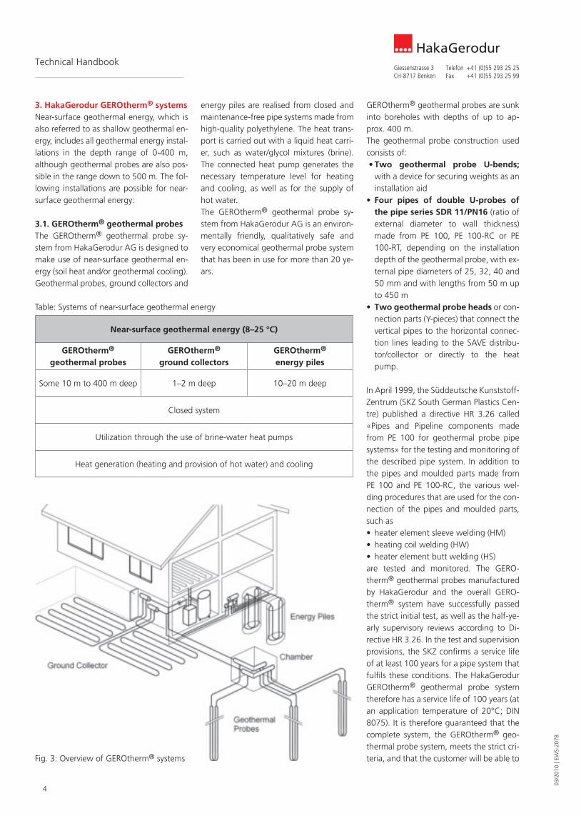
GEROtherm® geothermal probes are sunk into boreholes with depths of up to ap-prox. 400 m. The geothermal probe construction used consists of:• Two geothermal probe U-bends;
with a device for securing weights as an installation aid
• Four pipes of double U-probes of the pipe series SDR 11/PN16 (ratio of external diameter to wall thickness) made from PE 100, PE 100-RC or PE 100-RT, depending on the installation depth of the geothermal probe, with ex-ternal pipe diameters of 25, 32, 40 and 50 mm and with lengths from 50 m up to 450 m
• Two geothermal probe heads or con-nection parts (Y-pieces) that connect the vertical pipes to the horizontal connec-tion lines leading to the SAVE distribu-tor/collector or directly to the heat pump.
In April 1999, the Süddeutsche Kunststoff-Zentrum (SKZ South German Plastics Cen-tre) published a directive HR 3.26 called «Pipes and Pipeline components made from PE 100 for geothermal probe pipe systems» for the testing and monitoring of the described pipe system. In addition to the pipes and moulded parts made from PE 100 and PE 100-RC, the various wel-ding procedures that are used for the con-nection of the pipes and moulded parts, such as• heater element sleeve welding (HM)• heating coil welding (HW)• heater element butt welding (HS)are tested and monitored. The GERO-therm® geothermal probes manufactured by HakaGerodur and the overall GERO-therm® system have successfully passed the strict initial test, as well as the half-ye-arly supervisory reviews according to Di-rective HR 3.26. In the test and supervision provisions, the SKZ confirms a service life of at least 100 years for a pipe system that fulfils these conditions. The HakaGerodur GEROtherm® geothermal probe system therefore has a service life of 100 years (at an application temperature of 20°C; DIN 8075). It is therefore guaranteed that the complete system, the GEROtherm® geo-thermal probe system, meets the strict cri-teria, and that the customer will be able to
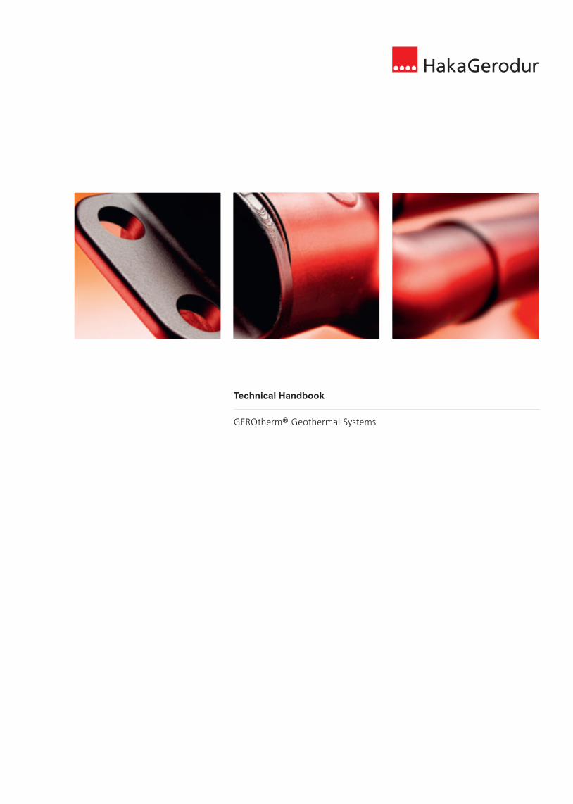
energy piles are realised from closed and maintenance-free pipe systems made from high-quality polyethylene. The heat trans-port is carried out with a liquid heat carri-er, such as water/glycol mixtures (brine). The connected heat pump generates the necessary temperature level for heating and cooling, as well as for the supply of hot water. The GEROtherm® geothermal probe sy-stem from HakaGerodur AG is an environ-mentally friendly, qualitatively safe and very economical geothermal probe system that has been in use for more than 20 ye-ars.
3. HakaGerodur GEROtherm® systemsNear-surface geothermal energy, which is also referred to as shallow geothermal en-ergy, includes all geothermal energy instal-lations in the depth range of 0-400 m, although geothermal probes are also pos-sible in the range down to 500 m. The fol-lowing installations are possible for near-surface geothermal energy:
3.1. GEROtherm® geothermal probesThe GEROtherm® geothermal probe sy-stem from HakaGerodur AG is designed to make use of near-surface geothermal en-ergy (soil heat and/or geothermal cooling). Geothermal probes, ground collectors and
Near-surface geothermal energy (8–25 °C)
GEROtherm® geothermal probes
GEROtherm® ground collectors
GEROtherm® energy piles
Some 10 m to 400 m deep 1–2 m deep 10–20 m deep
Closed system
Utilization through the use of brine-water heat pumps
Heat generation (heating and provision of hot water) and cooling
Fig. 3: Overview of GEROtherm® systems
Table: Systems of near-surface geothermal energy
5
03/2
010
| EW
S-20
78
HakaGerodurGiessenstrasse 3 Telefon +41 (0)55 293 25 25CH-8717 Benken Fax +41 (0)55 293 25 99
Technical Handbook
thermal energy pipes are approved for la-ying without a sand bed. The low additio-nal costs for the GEROtherm® KIT with PE 100-RC collectors saves an expensive re-placement of the excavated material by re-using it for the refilling.
3.3. GEROtherm® energy pilesEnergy piles are foundation piles (drilled or driven piles) that are fitted internally with HakaGerodur plastic pipes or «short» GEROtherm® geothermal probes as heat exchangers. Energy piles are employed above all in the rebuilding of buildings that makes a pile foundation necessary (mostly large constructions).
A differentiation is made between two models:• Drilled piles consist of reinforcement
baskets, to which the 10–20 m long GEROtherm® geothermal probes are fixed. After the fixation, the energy piles are sunk into a borehole and the bore-hole is then completely filled with con-crete.
Depending on the laying procedure for the ground collectors, various geothermal energy pipe systems with the correspondi-ng approvals are used:
Laying with a sand bed GEROtherm® ground collector PE 100, the classic model with SKZ HR3.26/A278 geothermal energy system mo-nitoring for laying with a sand bed
Laying without a sand bed GEROtherm® ground collector pipe PE 100-RC (high point loading and crack-resistance) with SKZ HR3.26/A278 ge-othermal energy system monitoring for laying without a sand bed
The use of the currently highest quality polyethylene materials creates the basis for making the installation more cost-ef-fective by avoiding the necessity of a sand bed. Geothermal energy pipe systems of the latest generation of polyethylene (so-called RC types) are thereby used here. These point-load and crack-resistant geo-
benefit from the performance over a long period.
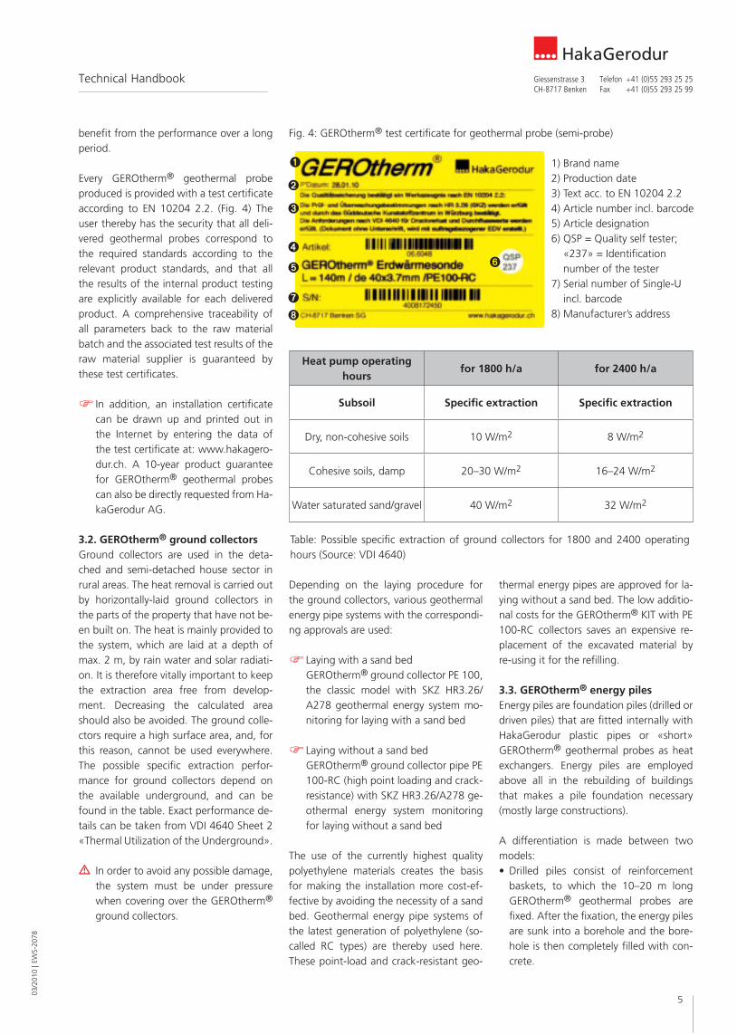
Every GEROtherm® geothermal probe produced is provided with a test certificate according to EN 10204 2.2. (Fig. 4) The user thereby has the security that all deli-vered geothermal probes correspond to the required standards according to the relevant product standards, and that all the results of the internal product testing are explicitly available for each delivered product. A comprehensive traceability of all parameters back to the raw material batch and the associated test results of the raw material supplier is guaranteed by these test certificates.
In addition, an installation certificate can be drawn up and printed out in the Internet by entering the data of the test certificate at: www.hakagero-dur.ch. A 10-year product guarantee for GEROtherm® geothermal probes can also be directly requested from Ha-kaGerodur AG.
3.2. GEROtherm® ground collectorsGround collectors are used in the deta-ched and semi-detached house sector in rural areas. The heat removal is carried out by horizontally-laid ground collectors in the parts of the property that have not be-en built on. The heat is mainly provided to the system, which are laid at a depth of max. 2 m, by rain water and solar radiati-on. It is therefore vitally important to keep the extraction area free from develop-ment. Decreasing the calculated area should also be avoided. The ground colle-ctors require a high surface area, and, for this reason, cannot be used everywhere. The possible specific extraction perfor-mance for ground collectors depend on the available underground, and can be found in the table. Exact performance de-tails can be taken from VDI 4640 Sheet 2 «Thermal Utilization of the Underground».
m In order to avoid any possible damage, the system must be under pressure when covering over the GEROtherm® ground collectors.
Fig. 4: GEROtherm® test certificate for geothermal probe (semi-probe)
1) Brand name2) Production date3) Text acc. to EN 10204 2.24) Article number incl. barcode5) Article designation6) QSP = Quality self tester;
«237» = Identification number of the tester
7) Serial number of Single-U incl. barcode
8) Manufacturer’s address
Heat pump operating hours
for 1800 h/a for 2400 h/a
Subsoil Specific extraction Specific extraction
Dry, non-cohesive soils 10 W/m2 8 W/m2
Cohesive soils, damp 20–30 W/m2 16–24 W/m2
Water saturated sand/gravel 40 W/m2 32 W/m2
Table: Possible specific extraction of ground collectors for 1800 and 2400 operating hours (Source: VDI 4640)

03/2
010
| EW
S-20
78
6
HakaGerodurGiessenstrasse 3 Telefon +41 (0)55 293 25 25CH-8717 Benken Fax +41 (0)55 293 25 99
Technical Handbook
wall thickness and pipe surface parame-ters is carried out in each extrusion line by means of ultrasonic measurements. In the case of deviations from the defined limit values of the parameters, there will be an automatic extraction of the pipe pieces. This ensures that no qualitatively ina-dequate geothermal probes leave the pro-duction factory.In addition, production samples will be checked at pre-defined, regular intervals in the long-period test bed. The GERO-therm® geothermal probes manufactured by HakaGerodur and the complete system have successfully passed the strict initial inspection, as well as the half-yearly super-vision controls according to SKZ Directive HR 3.26. In the test and supervision provi-sions for a pipe system, the SKZ confirms a service life of at least 100 years for a pipe system that fulfils these conditions. The HakaGerodur GEROtherm® geothermal probe system therefore has a service life of 100 years (at an application temperature of 20°C; DIN 8075). It is therefore guaran-teed that the complete system meets the strict criteria, and that the customer will be able to benefit from the performance over a long period
PE 100-RT is used when a higher tempera-ture resistance is required for the geother-mal probe. This can be the case with hot thermal sources or a combination of solar and geothermal energy systems. In the summer, the high solar radiation, and the-reby the high heat production of the colle-ctors, is thereby offset with the time-offset heat requirement for room heating in the winter. The energy gained in the collectors will be fed to the subsoil in the summer via the geothermal probe after reduction of the temperature level by means of a heat exchanger. The maximum temperature has to be defined according to the rele-vant regulations.
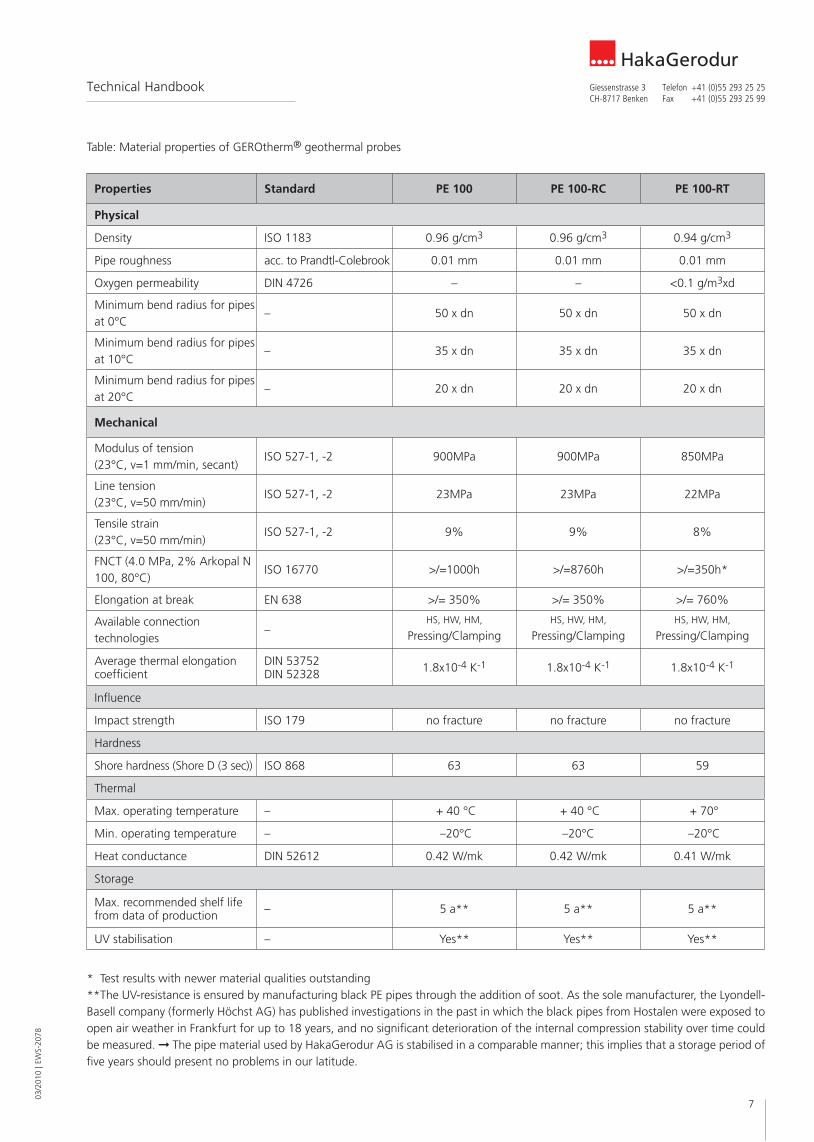
Depending on the different location fac-tors that are present at the object, geo-thermal probes from different materials can be selected. The following matrix pro-vides an overview of the different material properties. The values shown are average values.
Polyethylene has been used as a pipe ma-terial in the service supply sector (drinking water, heating, gas, industry, etc.) over the last 60 years. This has resulted in many ye-ars of experience in the manufacture, pro-cessing and use of this material. The poly-ethylene types used, PE 100, PE 100-RC and PE 100-RT, permit a long service life of 100 years @ 20°C, DIN 8075, according to the valid ISO, EN and DIN standards. The connection procedures, such as butt wel-ding (HS) and heating coil welding (HW), are well tested and require no other mate-rials. Seals or screw fittings in the soil can thereby be avoided. These are therefore material lock connections. The flexibility and the impact resistance of the material permits a problem-free installation of the components, even at extreme tempera-tures.Polyethylene has an optimal ecological ba-lance in comparison with other raw mate-rials (see Fig. 5).
Only new material that has been pro-cessed following a successful incoming material inspection is used as the starting material (granulate) for the manufacture of HakaGerodur GEROtherm® geothermal probe systems, and no recycled material is thereby used. The relevant parameters are continually monitored during the extrusi-on process. A 100% check of the geother-mal probes with regard to the dimension,
• In driven piles, the GEROtherm® geo-thermal probe has already been laid in the factory and has been cast in place with concrete. The driven piles are deli-vered complete to the construction site and are rammed into the subsoil. In do-ing this, it must be ensured that the line connections on the end of the pile are not damaged.
Energy piles are generally calculated by ex-perienced specialists.
3.4. Technical data for GEROtherm® systemsThe GEROtherm® systems are fully plastic systems made from high quality polyethy-lene materials PE 100 or PE 100-RC (Resi-stance to Crack) or PE 100-RT (Resistance to Temperature), which show optimal pro-perties for the geothermal energy applica-tions, such as:• Long service life (100 years @ 20°C; DIN
8075)• Low hydraulic resistance• No corrosion problems, as they are fully
plastic pipes• Resistant to cold and heat• Impact resistant• Installation-friendly modular system• Optimal safety with regard to pollution
of the soil (drinking water)• Patented probe foot (CH Pat. 687 268,
EU Pat. 1 036 974)
Fig. 5: Total greenhouse gas emissions in the manufacture, transport and disposal of various materials (Source: Georg Fischer GmbH, www.georgfischer.de)
7
03/2
010
| EW
S-20
78
HakaGerodurGiessenstrasse 3 Telefon +41 (0)55 293 25 25CH-8717 Benken Fax +41 (0)55 293 25 99
Technical Handbook
Table: Material properties of GEROtherm® geothermal probes
Properties Standard PE 100 PE 100-RC PE 100-RT
Physical
Density ISO 1183 0.96 g/cm3 0.96 g/cm3 0.94 g/cm3
Pipe roughness acc. to Prandtl-Colebrook 0.01 mm 0.01 mm 0.01 mm
Oxygen permeability DIN 4726 – – <0.1 g/m3xd
Minimum bend radius for pipes at 0°C
– 50 x dn 50 x dn 50 x dn
Minimum bend radius for pipes at 10°C
– 35 x dn 35 x dn 35 x dn
Minimum bend radius for pipes at 20°C
– 20 x dn 20 x dn 20 x dn
Mechanical
Modulus of tension (23°C, v=1 mm/min, secant)
ISO 527-1, -2 900MPa 900MPa 850MPa
Line tension (23°C, v=50 mm/min)
ISO 527-1, -2 23MPa 23MPa 22MPa
Tensile strain (23°C, v=50 mm/min)
ISO 527-1, -2 9% 9% 8%
FNCT (4.0 MPa, 2% Arkopal N 100, 80°C)
ISO 16770 >/=1000h >/=8760h >/=350h*
Elongation at break EN 638 >/= 350% >/= 350% >/= 760%
Available connection technologies
–HS, HW, HM,
Pressing/ClampingHS, HW, HM,
Pressing/ClampingHS, HW, HM,
Pressing/Clamping
Average thermal elongation coefficient
DIN 53752 DIN 52328 1.8x10⁻⁴ K-1 1.8x10⁻⁴ K-1 1.8x10⁻⁴ K-1
Influence
Impact strength ISO 179 no fracture no fracture no fracture
Hardness
Shore hardness (Shore D (3 sec)) ISO 868 63 63 59
Thermal
Max. operating temperature – + 40 °C + 40 °C + 70°
Min. operating temperature – –20°C –20°C –20°C
Heat conductance DIN 52612 0.42 W/mk 0.42 W/mk 0.41 W/mk
Storage
Max. recommended shelf life from data of production – 5 a** 5 a** 5 a**
UV stabilisation – Yes** Yes** Yes**
* Test results with newer material qualities outstanding**The UV-resistance is ensured by manufacturing black PE pipes through the addition of soot. As the sole manufacturer, the Lyondell-Basell company (formerly Höchst AG) has published investigations in the past in which the black pipes from Hostalen were exposed to open air weather in Frankfurt for up to 18 years, and no significant deterioration of the internal compression stability over time could be measured. The pipe material used by HakaGerodur AG is stabilised in a comparable manner; this implies that a storage period of five years should present no problems in our latitude.
03/2
010
| EW
S-20
78
8
HakaGerodurGiessenstrasse 3 Telefon +41 (0)55 293 25 25CH-8717 Benken Fax +41 (0)55 293 25 99
Technical Handbook
the cooling, as the geothermal probe would otherwise take up temperatures that are too high
• The separation between two geother-mal probes must be at least 5 m (for a depth up to 50 m) or 6 m (from a depth >50 m); the minimum distance from buildings must be at least 2 m
• The separation from neighbouring land should be at least 5 m
• The brine speed in the geothermal pro-be should lie within the range from 0.3 –0.7 m/s where possible; i.e. always within the turbulent range
• Geological expert reports are to be ob-tained, as the physical rock characteri-stics, and with them the specific extrac-tion performance at a specific location, can also vary with the geology
• The climate at the location will have a decisive effect on the extraction and yield performance of geothermal probes, and must therefore be taken into account in the planning
• Geothermal probe systems may not be used for the drying-out of the building
• The individual circuits of the geo thermal probe system are to be hydraulically matched (the corresponding regulation fittings are to be planned at the distributor/collector) and one shut- off device is to be planned per probe circuit
on to the drilling company involved, as geothermal probe systems are gene-rally subject to approval.
4.1. Planning basics4.1.1 General planning information
m In addition to the planning notes in VDI 4640 Sheet 2, September 2001, and SIA 384/6: 2010 (SN 546 384/6), the following points must be taken in-to account in the planning of a geo-thermal probe system:
• Geothermal probes are generally sub-ject to approval
• The dates on which the drilling will take place must be notified to the competent authorities
• An optimal system efficiency will be achieved through low flow tempera-tures
• As a rule, a detached house can be sup-plied using a GEROtherm® geothermal probe of 150–200 m without any addi-tional heating (i.e. monovalent)
• The overall heating and cooling require-ment of the object must be taken into account in the dimensioning of a probe field
• Guarantee of an optimal reconciliation of the energy flow within the building
• Geothermal probes with a maximum depth of 150 m are to be planned for
This data given are guidelines and can vary depending on the processing pro-cedures. In most cases, these are the average values of measurements car-ried out on several sample bodies. The listed technical characteristics are only intended as a planning guide. In parti-cular, they do not represent any gua-ranteed properties.
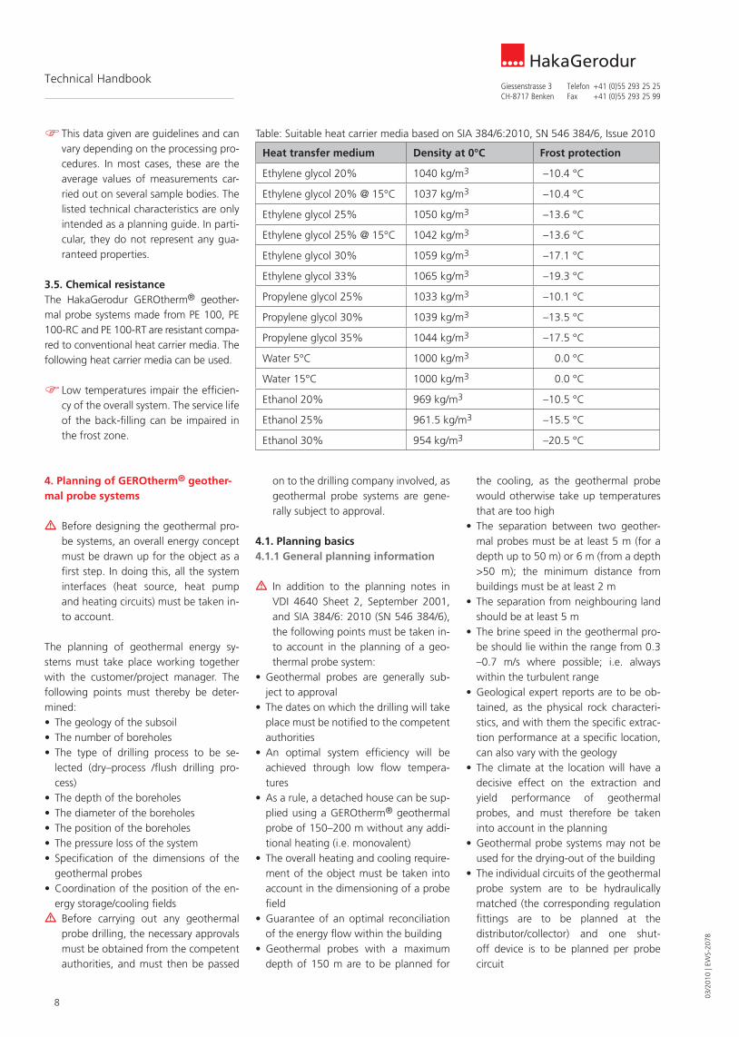
3.5. Chemical resistanceThe HakaGerodur GEROtherm® geother-mal probe systems made from PE 100, PE 100-RC and PE 100-RT are resistant compa-red to conventional heat carrier media. The following heat carrier media can be used.
Low temperatures impair the efficien-cy of the overall system. The service life of the back-filling can be impaired in the frost zone.
4. Planning of GEROtherm® geother-mal probe systems
m Before designing the geothermal pro-be systems, an overall energy concept must be drawn up for the object as a first step. In doing this, all the system interfaces (heat source, heat pump and heating circuits) must be taken in-to account.
The planning of geothermal energy sy-stems must take place working together with the customer/project manager. The following points must thereby be deter-mined:• The geology of the subsoil• The number of boreholes• The type of drilling process to be se-
lected (dry–process /flush drilling pro-cess)
• The depth of the boreholes• The diameter of the boreholes• The position of the boreholes• The pressure loss of the system• Specification of the dimensions of the
geothermal probes• Coordination of the position of the en-
ergy storage/cooling fieldsm Before carrying out any geothermal
probe drilling, the necessary approvals must be obtained from the competent authorities, and must then be passed
Table: Suitable heat carrier media based on SIA 384/6:2010, SN 546 384/6, Issue 2010
Heat transfer medium Density at 0°C Frost protection
Ethylene glycol 20% 1040 kg/m3 –10.4 °C
Ethylene glycol 20% @ 15°C 1037 kg/m3 –10.4 °C
Ethylene glycol 25% 1050 kg/m3 –13.6 °C
Ethylene glycol 25% @ 15°C 1042 kg/m3 –13.6 °C
Ethylene glycol 30% 1059 kg/m3 –17.1 °C
Ethylene glycol 33% 1065 kg/m3 –19.3 °C
Propylene glycol 25% 1033 kg/m3 –10.1 °C
Propylene glycol 30% 1039 kg/m3 –13.5 °C
Propylene glycol 35% 1044 kg/m3 –17.5 °C
Water 5°C 1000 kg/m3 0.0 °C
Water 15°C 1000 kg/m3 0.0 °C
Ethanol 20% 969 kg/m3 –10.5 °C
Ethanol 25% 961.5 kg/m3 –15.5 °C
Ethanol 30% 954 kg/m3 –20.5 °C

9
03/2
010
| EW
S-20
78
HakaGerodurGiessenstrasse 3 Telefon +41 (0)55 293 25 25CH-8717 Benken Fax +41 (0)55 293 25 99
Technical Handbook
the geothermal probe field in order to also be able to avoid the use of flow regulation fittings here.
If these are unavoidable, however, we would recommend the well-proven SET-TER balancing valves. These are available for measurement ranges from 2–180 l/min. It should be noted, however, that lar-ge pressure losses could arise from the ba-lancing effect in the case of large diffe-rences in the flow resistance.
m Individual circuits of the earth collec-tors and the geothermal probes must be able to be individually shut off. The problem-free venting of the system is thereby always possible during com-missioning and any necessary service work.
The GEROtherm® distributors/collectors (feed and return) made from PE 100 meet the set requirements; they are constructed as a modular system. The individual sizes are available for the connection of geo-thermal probes, earth collectors or energy piles. Geothermal probe pipes with exter-nal diameters of Ø25, Ø32, Ø40 and Ø50 mm can be connected.
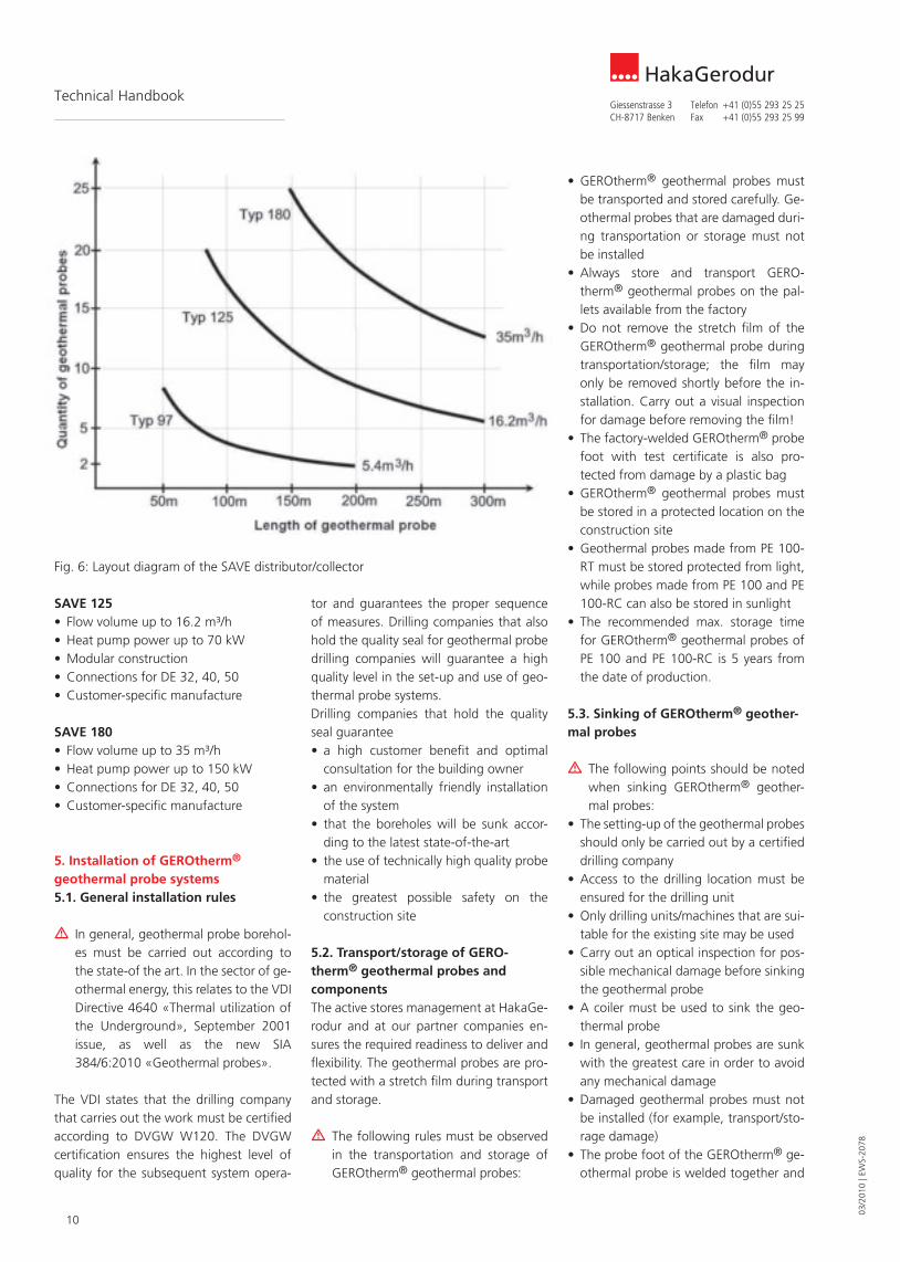
Selection of suitable GEROtherm® distributors/collectors for geothermal probesThe distributors/collectors should be de-termined on the basis of the required flow volumes for the heat pump (flow volume in m³/h).The accumulated probe length can also be used as the selection criterion Fig. 6):• Up to approx. 300 m: Model 97/97L• Up to approx. 1400 m: Model 125• Up to approx. 3000 m: Model 180Larger outputs can be achieved through the parallel connection of the SAVE distri-butors/collectors.
SAVE 97/SAVE 97L• Flow volume up to 5.4 m³/h• Heat pump power up to 16 kW• 2 to 8 connections• Connections for DE 25, 32, 40• Stock article
m Dry soil has a lower extraction perfor-mance (< 30 W/m), whereas earth la-yers that carry groundwater have a higher extraction performance of up to 80 W/m.
m In systems with three or more GERO-therm® geothermal probes, a lower extraction performance should be se-lected on the basis of their mutual in-teraction, as well as in the case of ge-othermal probe system in mountainous regions.
m Complex systems are to be dimensi-oned in detail by a planning office, and the carrying out of a Thermal Re-sponse Tests (TRT) is recommended for the design of the overall system.
m The mean brine temperature deter-mined at the inlet and outlet of the geothermal probe is a decisive criteria for the design.
m A minimum brine temperature of –1.5°C (e.g. inlet of the geothermal probe –3°C, outlet 0°C) after 50 years of operation is necessary for the ex-traction of heat.
4.1.3. Design of the SAVE distributor/collectorThe GEROtherm® distributors/collectors from HakaGerodur are dimensioned in a correspondingly generous manner, and thereby only result in minimal flow resi-stance (~15 mbar).
The geothermal probes should be con-nected to the distributor/collector with feed and return lines that have the sa-me length as far as possible. Expensive flow regulation fittings can thereby be avoided. A difference in the flow volu-me of up to +/- 15% is permissible.
In the case of large systems, it is re-commended that one or more distri-butor shafts be set up in the middle of
• The mutual interaction of geothermal probes is to be taken into account in the planning
• The selected heat transfer medium must be suitable for the selected tempera-tures
• The heat carrier temperature must not fall below a mean minimum of -1.5°C (for example, inlet to the geothermal probe –3°C, outlet 0°C) during the enti-re operation
4.1.2. Dimensioning of GEROtherm® geothermal probesThe dimensioning of geothermal probe sy-stems must be carried out by an approved engineering or planning office. The corre-spondingly valid standards and directives, as well as the existing geology, must be taken into account in the planning.For smaller objects (single-family house), the nomogram of VDI 4640 can also be used as a first reference point for the rough assessment of the design of the ge-othermal probe system. The reading must always be checked mathematically, howe-ver. SIA 384/6:2010 describes the calcula-tion and design of geothermal probe sy-stems in detail.The GEROtherm® probe length can be roughly determined mathematically as shown in the following example, taking the heat requirement determination and the existing geological soil conditions into account. The extraction performance of the GEROtherm® geothermal probe corre-sponds to the cooling performance of the selected heat pump. The heating perfor-mance of the heat pump must correspond to the heating requirement of the building.The complete heat requirement of the de-tached house, including the production of hot water, can be covered with a 150 m GEROtherm® geothermal probe.
Example: Detached house, new building, living area approx. 200 m2
Heat requirement: 13.0 kW
COP heat pump: 4.0 at BO-W35 (COP=Coefficient of Performance = efficiency)
Heat pump cooling performance: 9.7 kW
Extraction performance of soil: 50 W/m (depending on the existing geological soil conditions!)
145.5 m50W/m
0.4
9.7kW9.7kW-
Extraction performanceCOP
Heatpump cooling performance – Heatpump cooling performance
GEROtherm length of probe ===
03/2
010
| EW
S-20
78
10
HakaGerodurGiessenstrasse 3 Telefon +41 (0)55 293 25 25CH-8717 Benken Fax +41 (0)55 293 25 99
Technical Handbook
• GEROtherm® geothermal probes must be transported and stored carefully. Ge-othermal probes that are damaged duri-ng transportation or storage must not be installed
• Always store and transport GERO-therm® geothermal probes on the pal-lets available from the factory
• Do not remove the stretch film of the GEROtherm® geothermal probe during transportation/storage; the film may only be removed shortly before the in-stallation. Carry out a visual inspection for damage before removing the film!
• The factory-welded GEROtherm® probe foot with test certificate is also pro-tected from damage by a plastic bag
• GEROtherm® geothermal probes must be stored in a protected location on the construction site
• Geothermal probes made from PE 100-RT must be stored protected from light, while probes made from PE 100 and PE 100-RC can also be stored in sunlight
• The recommended max. storage time for GEROtherm® geothermal probes of PE 100 and PE 100-RC is 5 years from the date of production.
5.3. Sinking of GEROtherm® geother-mal probes
m The following points should be noted when sinking GEROtherm® geother-mal probes:
• The setting-up of the geothermal probes should only be carried out by a certified drilling company
• Access to the drilling location must be ensured for the drilling unit
• Only drilling units/machines that are sui-table for the existing site may be used
• Carry out an optical inspection for pos-sible mechanical damage before sinking the geothermal probe
• A coiler must be used to sink the geo-thermal probe
• In general, geothermal probes are sunk with the greatest care in order to avoid any mechanical damage
• Damaged geothermal probes must not be installed (for example, transport/sto-rage damage)
• The probe foot of the GEROtherm® ge-othermal probe is welded together and
tor and guarantees the proper sequence of measures. Drilling companies that also hold the quality seal for geothermal probe drilling companies will guarantee a high quality level in the set-up and use of geo-thermal probe systems.Drilling companies that hold the quality seal guarantee• a high customer benefit and optimal
consultation for the building owner• an environmentally friendly installation
of the system• that the boreholes will be sunk accor-
ding to the latest state-of-the-art• the use of technically high quality probe
material• the greatest possible safety on the
construction site
5.2. Transport/storage of GERO-therm® geothermal probes and componentsThe active stores management at HakaGe-rodur and at our partner companies en-sures the required readiness to deliver and flexibility. The geothermal probes are pro-tected with a stretch film during transport and storage.
m The following rules must be observed in the transportation and storage of GEROtherm® geothermal probes:
SAVE 125• Flow volume up to 16.2 m³/h• Heat pump power up to 70 kW• Modular construction• Connections for DE 32, 40, 50• Customer-specific manufacture
SAVE 180• Flow volume up to 35 m³/h• Heat pump power up to 150 kW• Connections for DE 32, 40, 50• Customer-specific manufacture
5. Installation of GEROtherm® geothermal probe systems5.1. General installation rules
m In general, geothermal probe borehol-es must be carried out according to the state-of the art. In the sector of ge-othermal energy, this relates to the VDI Directive 4640 «Thermal utilization of the Underground», September 2001 issue, as well as the new SIA 384/6:2010 «Geothermal probes».
The VDI states that the drilling company that carries out the work must be certified according to DVGW W120. The DVGW certification ensures the highest level of quality for the subsequent system opera-
Fig. 6: Layout diagram of the SAVE distributor/collector

11
03/2
010
| EW
S-20
78
HakaGerodurGiessenstrasse 3 Telefon +41 (0)55 293 25 25CH-8717 Benken Fax +41 (0)55 293 25 99
Technical Handbook
• The injection pipe is to be secured on the probe foot and be sunk down to the upper edge of the geothermal probe foot
5.4. Test procedure after the sinking (pressure check/flow check analogous to SIA 384/6:2010)
m The checks on the installed geother-mal probes are to be carried out analo-gous to SIA 384/6 (issue 2010). The acceptance test includes three checks, for which all the measurement results are to be recorded in writing in an ac-ceptance report:
• Flushing: Each geothermal probe circuit
must be completely flushed out at least once
• Flow-through check: The differential pressure between the feed and the re-turn will be measured at a constant flow rate, and will be compared with the the-oretical value given in the SIA standard. The deviation between the two values may not exceed +/-15%
• Leakage test: This test must take place immediately after the back-filling, simi-lar to SN EN 805.
• In the case of dry drilling, it is recom-mended that the borehole be filled to good 1/3 with water before the empty or partly filled probe is sunk. If the pro-be is in place, it should then be filled with water. The geothermal probe must be secured in order to prevent any floa-ting up of the probe during the injec-tion.
• Protruding piping from the sunk geo-thermal probes must be protected against damage on the construction site
• Geothermal probes must be firmly sealed up with caps up to the connec-tion to the SAVE distributor/collector, and the caps must be secured with adhesive tape
• The distance between two geothermal probes must be at least 5 m (for a depth down to 50 m) or 6 m (for a depth >50 m); the minimum distance from buil-dings must be at least 2 m
• Chronological reporting of the drilling work by the machine operator (see the Sample Drilling Report in the appendix)
• The waste water arising from the drilling must be disposed of according to the valid regulations
• The pipe work must be carefully remo-ved without damaging the geothermal probe any twisting of the geothermal probe must be avoided
checked 100% in the factory. Welding a probe foot on the construction site is not permitted.
• Always sink the GEROtherm® geother-mal probe with a weight (12.5 kg or 24 kg)
• As a maximum, a total weight of 100 kg may be attached per Single-U for the sinking of the geothermal probe
• The geothermal probe must not be sub-jected to any high dynamic forces duri-ng the sinking
• The pressure relationships must be ob-served while installing the geothermal probe – and, in particular, the differenti-al pressure (inner/outer pressure). The differential pressure must not exceed 21 bar internal pressure (inner to outer) du-ring the installation and the compressi-on process or 8 bar external pressure (outer to inner)!
• Sealing using the GEOtight fabric pa-cker for geothermal probes if ground-water, or water or gas under pressure appears in the borehole
An installation certificate can be crea-ted and printed out in the Internet at: www.hakagerodur.ch by entering the serial number of the GEOtight fabric packer.
1 Universal adaptor fitting 2 Air vent 3 Wall lead-through 4 SAVE distributor with ball valves 5 SAVE collector w. balancing valves 6 Y-piece 7 GEROtherm® geothermal probe 8 Probe foot deflectors 9 Weight for the geothermal probes 10 Brine circulation pump 11 Heat pump 12 Safety valve 13 Manometer 14 Expansion vessel 15 Filling/emptying valve
Fig. 7: Installation overview of the GEROtherm® SAVE distributor/collector

03/2
010
| EW
S-20
78
12
HakaGerodurGiessenstrasse 3 Telefon +41 (0)55 293 25 25CH-8717 Benken Fax +41 (0)55 293 25 99
Technical Handbook
After a further 10 minutes: 2nd pressure measurement After a further 10 minutes: 3rd and final pressure measurement
The pressure test has been passed if a maximum pressure drop of less than 0.1 bar is determined at the 3rd mea-surement compared to the 1st mea-surement.
Material: Manometer with a resolution better than 0.01 bar, pressure range corre-sponding to the test, minimum 12 bar; 2 valve; purge; pressure pump; 1 l measu-ring cup; All connections are to be desi-gned for 16 bar.The results are to be entered into a report or are to be printed out as a diagram cor-responding to the example below.
5.5. Back-filling the boreholeThe back-filling of the borehole has basi-cally three purposes; to create a complete and permanent seal, to ensure stability and to ensure a high heat conductance (SIA 384/6).
m The following rules are to be followed in the back-filling of the borehole:
• During the back-filling, the geothermal probe pipes must be completely filled with water, be sealed pressure-tight at the top and be fitted with a pressure gauge (manometer), so that the pipes will not be pressed together and so that any possible pressure drop can be de-tected.
• When pressing in the geothermal probes, the pressure conditions must be observed – in particular, the differential pressure (inner over-pressure/outer pres-sure). The differential pressure may not lie above 21 bar inner positive pressure (inside to outside) during the pressing process, or 8 bar external positive pres-sure (outside to inside)!
• The injection pipes are designed for a short-term (< 1 h) maximum pressure of 34 bar at 20°C (with higher external temperatures, the maximum permissible pressure reduces by 40–50%!).
• Secure the filling pipe to the geothermal probe foot and insert it into the bore-hole during the sinking of the geother-mal probe.
minimum of 7.5 bar, and that a pressure of 21 bar will not be exceeded over the complete length.
Implementation:Check that the above-mentioned precon-ditions have been fulfilled.a) 1 h rest time in the unloaded state for
the pipes that are to be measured b) Build-up of the test pressure (10...12
bar)c) Maintenance of the test pressure for 10
minutesd) Waiting period of 1 hour, during which
the pipe can fully expand e) Measurement of the remaining pressure.
A decrease of 30% compared to the test pressure is acceptable due to the pipe ex-pansion. Larger deviations could be due to air pockets or leakages. The test will have to be restarted from Point a).
Rapid pressure relief by 2 bar by the discharge of water. The amount of drained water and the new pressure va-lue are to be measured. Check the wa-ter volume according to SIA 384/6.
f) After 10 minutes: 1st pressure measure-ment
Leakage test according to SIA 384/6 (2010 issue)
The following preconditions must be com-plied with in the test:
Horizontal interconnection lines:• Constant temperature of the pipe wall
throughout the duration of the test• No direct sunlight on the pipesGeothermal probes:• Complete back-filling with a plastic or
free-flowing suspension, and the sus-pension has not cured
• In fissure zones and in permeable areas where, in agreement with the responsi-ble authorities, the back-filling is not completely carried out, the pressure test must be adapted to the circumstances in order to prevent any damage to the geothermal probe tubes. This also ap-plies in the case of back-filling with other densities.
• The test pressure is to be selected so that the over-pressure in the pipes at the foot of the geothermal probe will amount to 0.5 bar throughout the enti-re test, that the head pressure will be a
Fig. 8: Pressure testing of the geothermal probes on the basis of SN EN 805
13
03/2
010
| EW
S-20
78
HakaGerodurGiessenstrasse 3 Telefon +41 (0)55 293 25 25CH-8717 Benken Fax +41 (0)55 293 25 99
Technical Handbook
• Only welded connections may be used for connections that are to be laid in the ground!
• Establishing of connections (welded connections) by trained specialists (welder’s certificate according to VDS or Welder’s Passport according to VKR)
• The pipe trench is to be dug so that the prescribed minimum coverage of 1.0– 1.8 m depending on the climate and soil will be guaranteed for all the connec-tion lines.
• The valid safety regulations of the aut-horities must be followed when carrying out the excavation of the trench!
• The base of the trench is to be dug so that the pipelines will lie on it evenly
• In the case of several feed/return runs, these must be laid in one trench in such a way that they will be thermally separa-ted from each other
• All connection runs are to be of the same length and are to be laid with a uniform gradient down to the geother-mal probes
• The use of approved, tested and maintained tools
• Welded connection are to be individual-ly marked with the date, time and signa-ture (proof of the connection welding carried out Fill in a welding report)
• A venting unit is to be fitted to each dis-tributor/collector, or at the highest point of the system
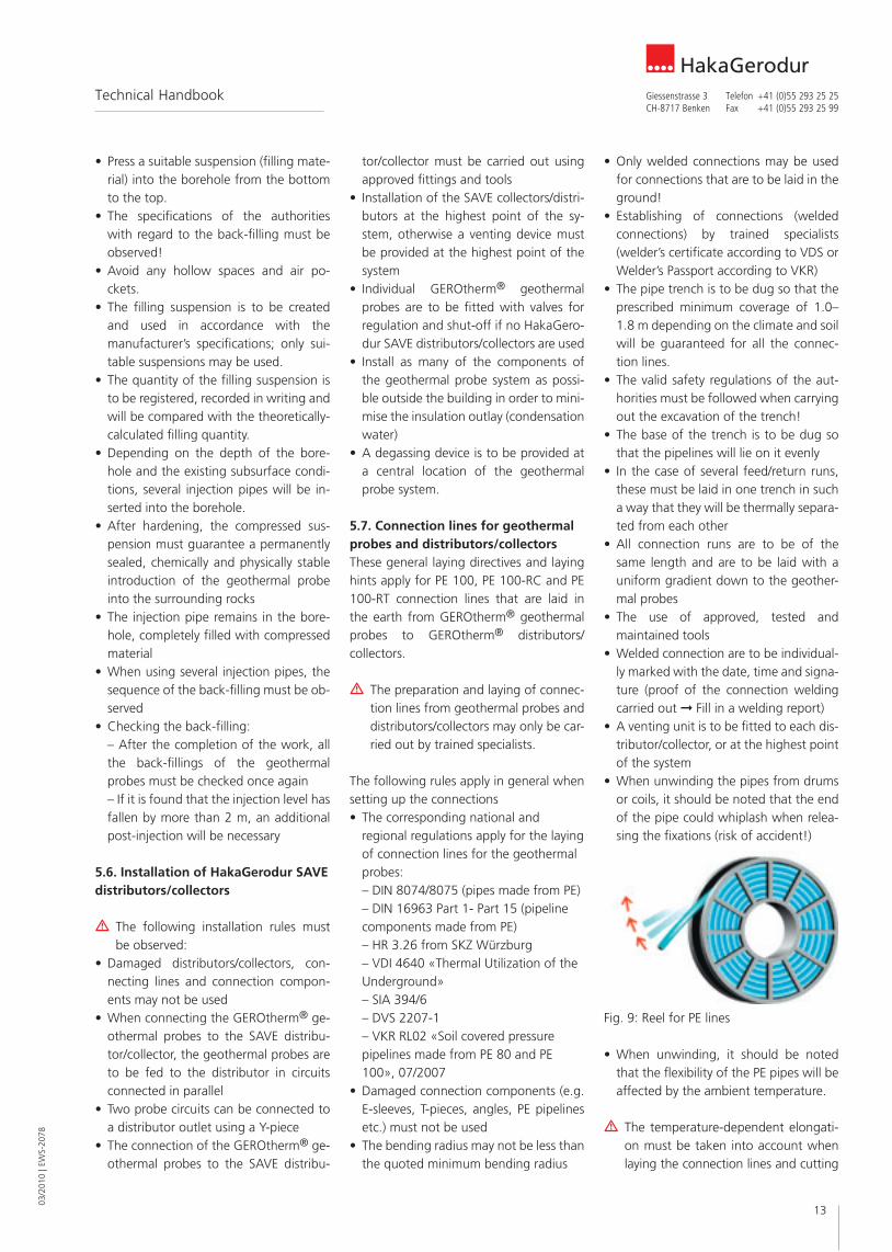
• When unwinding the pipes from drums or coils, it should be noted that the end of the pipe could whiplash when relea-sing the fixations (risk of accident!)
• When unwinding, it should be noted that the flexibility of the PE pipes will be affected by the ambient temperature.
m The temperature-dependent elongati-on must be taken into account when laying the connection lines and cutting
tor/collector must be carried out using approved fittings and tools
• Installation of the SAVE collectors/distri-butors at the highest point of the sy-stem, otherwise a venting device must be provided at the highest point of the system
• Individual GEROtherm® geothermal probes are to be fitted with valves for regulation and shut-off if no HakaGero-dur SAVE distributors/collectors are used
• Install as many of the components of the geothermal probe system as possi-ble outside the building in order to mini-mise the insulation outlay (condensation water)
• A degassing device is to be provided at a central location of the geothermal probe system.
5.7. Connection lines for geothermal probes and distributors/collectorsThese general laying directives and laying hints apply for PE 100, PE 100-RC and PE 100-RT connection lines that are laid in the earth from GEROtherm® geothermal probes to GEROtherm® distributors/ collectors.
m The preparation and laying of connec-tion lines from geothermal probes and distributors/collectors may only be car-ried out by trained specialists.
The following rules apply in general when setting up the connections• The corresponding national and
regional regulations apply for the laying of connection lines for the geothermal probes: – DIN 8074/8075 (pipes made from PE) – DIN 16963 Part 1- Part 15 (pipeline components made from PE) – HR 3.26 from SKZ Würzburg – VDI 4640 «Thermal Utilization of the Underground» – SIA 394/6 – DVS 2207-1 – VKR RL02 «Soil covered pressure pipelines made from PE 80 and PE 100», 07/2007
• Damaged connection components (e.g. E-sleeves, T-pieces, angles, PE pipelines etc.) must not be used
• The bending radius may not be less than the quoted minimum bending radius
• Press a suitable suspension (filling mate-rial) into the borehole from the bottom to the top.
• The specifications of the authorities with regard to the back-filling must be observed!
• Avoid any hollow spaces and air po-ckets.
• The filling suspension is to be created and used in accordance with the manufacturer’s specifications; only sui-table suspensions may be used.
• The quantity of the filling suspension is to be registered, recorded in writing and will be compared with the theoretically-calculated filling quantity.
• Depending on the depth of the bore-hole and the existing subsurface condi-tions, several injection pipes will be in-serted into the borehole.
• After hardening, the compressed sus-pension must guarantee a permanently sealed, chemically and physically stable introduction of the geothermal probe into the surrounding rocks
• The injection pipe remains in the bore-hole, completely filled with compressed material
• When using several injection pipes, the sequence of the back-filling must be ob-served
• Checking the back-filling: – After the completion of the work, all the back-fillings of the geothermal probes must be checked once again – If it is found that the injection level has fallen by more than 2 m, an additional post-injection will be necessary
5.6. Installation of HakaGerodur SAVE distributors/collectors
m The following installation rules must be observed:
• Damaged distributors/collectors, con-necting lines and connection compon-ents may not be used
• When connecting the GEROtherm® ge-othermal probes to the SAVE distribu-tor/collector, the geothermal probes are to be fed to the distributor in circuits connected in parallel
• Two probe circuits can be connected to a distributor outlet using a Y-piece
• The connection of the GEROtherm® ge-othermal probes to the SAVE distribu-
Fig. 9: Reel for PE lines

03/2
010
| EW
S-20
78
14
HakaGerodurGiessenstrasse 3 Telefon +41 (0)55 293 25 25CH-8717 Benken Fax +41 (0)55 293 25 99
Technical Handbook
9. Connect the cable of the welding unit to the electrofusion fitting socket with the weight relieved.
10. Where necessary, check the settings and/or the data display on the device display, and enter the welding data (scanning the barcode of the electro-fusion fitting).
11. Carry out the welding sequence as described in the manufacturer data, and check the result.
12. After finishing the welding, remove the unit cable from the electrofusion fitting.
13. Observe the cooling-down time ac-cording to the manufacturer’s data.
14. If no automatic logging has taken place, a welding report is to be drawn up by hand + the weld is to be mar-ked in writing (date, signature, time after the end of the cooling time)
Correctly executed heated-coil welding may only be carried out once per coupler!
5.8. Filling the GEROtherm® Geother-mal probe system and the pressure test
m The operating instructions for the he-at pump are to be followed. The fil-ling and the carrying out of a pressure test probe may only be carried out by specialists. The test report is to be handed over to the building owner. The following important points must be observed when filling:
• The filling of the GEROtherm® geother-mal probe system may only be carried out with the permissible heat carrier media that do not endanger water (see table in Section 3.5.).
• Other liquids may not be used. • All connected geothermal probes are to
be individually flushed out until total freedom of air before the filling. Air po-ckets are to be avoided in all cases.
• Each probe circuit must be filled indivi-dually and the filling quantity per circuit must be checked
• The flushing must take place in both directions with sufficiently large flus-hing pumps
• The concentration of the brine is to be set up here according to the data from the heat pump manufacturer and is to be recorded in writing.
them to length. The pipe becomes lon-ger with an increase in temperature, and, with a fall in temperature, a 1 me-tre length of PE pipe reduces in length by 0.2 mm per °K! On the basis of the certification from an independent test institute, GERO-therm® connection lines made from PE 100-RC are suitable for laying without a sand bed. The back-filling of the pipe trench is carried out with material that corresponds to the compression classifi-cations V1–V3 of the ZTVA StB 97. Heated-coil welding (HW) is recom-mended for the connection of GERO-therm® geothermal probes to the con-nection line to the distributor/collector, and high quality ELGEF® Plus connec-tion elements are available for this. The ELGEF® Plus modular system offers the greatest flexibility.
Summary of the work instructions according to DVS 2207-1 for the heated-coil welding of GEROtherm® EWS and connection lines, Y-pieces, distributors/collectors made from PE 100 and PE 100-RC:1. Set up the permissible working condi-
tions; e.g. protection from damp, wind, temperatures < 0°C, etc.
2. Connect the welding unit to the power source and check its functionality.
3. De-bur the right-angle separated geo-thermal probe ends on the outside.
4. Where necessary, ensure the roundness of the pipe ends using re-rounding tools, permissible ovality 1.5%.
5. Machine the tube surface by removing metal with a rotation peeler (constant chip removal max. 0.2 mm).
6. Remove the electrofusion fittings from their original packaging
7. Clean the machined surface of the GEROtherm® geothermal probes and the inner surface of the electrofusion fitting with a cleaning liquid that is ap-proved for PE surfaces (e.g. Tangit clea-ner; refer to the safety data sheet) and a lint-free, ink-free paper.
8. Insert the geothermal probe and con-nection pipe with parallel faces and wi-thout force into the electrofusion fitting, secure with the integrated screws and visibly mark the insertion depth. CAUTI-ON: Ensure the correct insertion depth!
Fig. 10: Comply wirth the permissible wor-king
Fig. 11: Metal cutting machining in the weld area
Fig. 12: Cleaning the machined surface
Fig. 13: Scanning the parameters, weld and observe the cooling time

15
03/2
010
| EW
S-20
78
HakaGerodurGiessenstrasse 3 Telefon +41 (0)55 293 25 25CH-8717 Benken Fax +41 (0)55 293 25 99
Technical Handbook
7. Maintenance of GEROtherm® geothermal probe systems
A GEROtherm® geothermal probe system is generally maintenance-free. Standard heat pumps are also mostly maintenance-free. Please check the corresponding maintenance instructions of your heat pump manufacturer in this respect.
The filling pressure of the geothermal pro-be should be checked annually. Refill quantities are to be logged.
8. Shutting down geothermal probe systems
When putting geothermal probes out of service, the heat transfer medium must be completely flushed out, and be disposed of correctly in accordance with the appli-cable regulations.The geothermal probe is then to be com-pletely and fully pressed down with cured material. The proper shut-down of the ge-othermal probe system is to be reported to the responsible authorities.
9. AppendixRelevant charts and printouts can be found on the following pages.
m The brine must be homogenously mixed before the filling. The material Safety Data Sheets (MSDS) for the che-micals used must be observed.
The following table gives a summary of the volumes per m of GEROtherm® geo-thermal probe for the determination of the necessary brine volume.
If the system has been completely filled, the pressure test takes place with 1.5 times the operational pressure. The fol-lowing is to be noted here:• All brine circuits are to be subjected to
the pressure test.• Only a suitable heat transfer medium is
to be used as the pressure test liquid. • Sensitive fittings (e.g. safety group ex-
pansion vessel) are to be corresponding safeguarded.
• The pressure conditions in the geother-mal probe are to be monitored (see Sec-tions 5.3.– 5.5.)
Once the pressure test has been com-pleted, components that were removed are to be put back into operation.
6. Operation of GEROtherm® geo-thermal probe systems
The initial commissioning must be carried out by a specialist company. The informa-tion and operating instructions of the heat pump manufacturers are to be followed!It is imperative to observe the following before commissioning the geothermal probe system with heat pump:– All brine circuits must be vented and be
filled with the homogenously mixed heat transfer medium
– All fittings must be in their operating positions
GEROtherm®
(outer diameter/wall thickness) Double U-probe (2 circuits/4 pipes)
25 mm (25 x 2.3 mm) 1.31 litres/m (4 x 0.327 litre/m)
32 mm (32 x 2.9 mm) 2.14 litres/m (4 x 0.535 litre/m)
40 mm (40 x 3.7 mm) 3.34 litres/m (4 x 0.835 litre/m)
50 mm (50 x 4.6 mm) 5.23 litres/m (4 x 1.307 litre/m)
Table: Overview of volume per m geothermal probe

03/2
010
| EW
S-20
78
16
HakaGerodurGiessenstrasse 3 Telefon +41 (0)55 293 25 25CH-8717 Benken Fax +41 (0)55 293 25 99
Technical Handbook
9.1. Pressure loss tables of water in pipes PE 100 S 5/PN 16/SDR 11
de x e 25 x 2.3 mm 32 x 2.9 mm 40 x 3.7 mml/m 0.835v Q R Q R Q R
m/s l/s mbar/m l/s mbar/m l/s mbar/m0.10 0.0327 0.10 0.0531 0.062 0.0835 0.0730.15 0.0490 0.27 0.0796 0.200 0.1250 0.1500.20 0.0654 0.44 0.1060 0.320 0.1670 0.2400.25 0.0817 0.65 0.1330 0.470 0.2090 0.350
0.30 0.0981 0.90 0.1590 0.650 0.2500 0.4900.35 0.1140 1.18 0.1860 0.860 0.2920 0.6400.40 0.1310 1.49 0.2120 1.090 0.3340 0.8100.45 0.1470 1.84 0.2390 1.340 0.3760 1.0000.50 0.1630 2.22 0.2650 1.620 0.4170 1.210
0.55 0.1800 2.63 0.2920 1.920 0.4590 1.4400.60 0.1960 3.07 0.3190 2.250 0.5010 1.6800.65 0.2120 3.55 0.3450 2.600 0.5430 1.9500.70 0.2290 4.06 0.3720 2.970 0.5840 2.2300.75 0.2450 4.60 0.3980 3.370 0.6260 2.530
0.80 0.2610 5.17 0.4250 3.790 0.6680 2.8400.85 0.2780 5.78 0.4510 4.230 0.7090 3.1700.90 0.2940 6.41 0.4780 4.700 0.7510 3.5200.95 0.3110 7.08 0.5040 5.190 0.7930 3.8901.00 0.3270 7.78 0.5310 5.700 0.8350 4.280
de x e 50 x 4.6 mm 63 x 5.8 mm 75 x 6.8 mml/m 1.307 2.074 2.960v Q R Q R Q R
m/s l/s mbar/m l/s mbar/m l/s mbar/m0.10 0.1310 0.054 0.2070 0.040 0.2940 0.0320.15 0.1960 0.110 0.3110 0.081 0.4410 0.0640.20 0.2610 0.180 0.4150 0.130 0.5880 0.1100.25 0.3270 0.270 0.5190 0.200 0.7350 0.160
0.30 0.3920 0.370 0.6220 0.270 0.8820 0.2200.35 0.4580 0.480 0.7260 0.360 1.0300 0.2900.40 0.5230 0.610 0.8300 0.460 1.1770 0.3700.45 0.5880 0.750 0.9340 0.560 1.3240 0.4500.50 0.6540 0.910 1.0370 0.680 1.4710 0.550
0.55 0.7190 1.080 1.1410 0.810 1.6180 0.6500.60 0.7840 1.270 1.2450 0.950 1.7650 0.7600.65 0.8500 1.460 1.3490 1.090 1.9120 0.8800.70 0.9150 1.680 1.4520 1.250 2.0590 1.0100.75 0.9810 1.900 1.5560 1.420 2.2060 1.140
0.80 1.0460 2.140 1.6600 1.600 2.3530 1.2800.85 1.1110 2.390 1.7640 1.790 2.5000 1.4400.90 1.1770 2.650 1.8670 1.980 2.6470 1.6000.95 1.2420 2.930 1.9710 2.190 2.7950 1.7601.00 1.3070 3.220 2.0750 2.410 2.9420 1.940

17
03/2
010
| EW
S-20
78
HakaGerodurGiessenstrasse 3 Telefon +41 (0)55 293 25 25CH-8717 Benken Fax +41 (0)55 293 25 99
Technical Handbook
9.1. Pressure loss tables of water in pipes PE 100 S 5/PN 16/SDR 11
de x e 90 x 8.2 mm 110 x 10.0 mm 125 x 11.4 mml/m 4.252 6.359 8.199v Q R Q R Q R
m/s l/s mbar/m l/s mbar/m l/s mbar/m0.10 0.4250 0.0250 0.636 0.0190 0.820 0.0160.15 0.6380 0.0510 0.954 0.0390 1.231 0.0330.20 0.8510 0.0840 1.272 0.0650 1.641 0.0560.25 1.0640 0.1300 1.590 0.0970 2.051 0.083
0.30 1.2760 0.1700 1.909 0.130 2.461 0.1100.35 1.4890 0.2300 2.227 0.180 2.871 0.1500.40 1.7020 0.2900 2.545 0.230 3.281 0.1900.45 1.9150 0.3600 2.863 0.280 3.692 0.2400.50 2.1270 0.4300 3.181 0.340 4.102 0.290
0.55 2.3400 0.5100 3.499 0.400 4.512 0.3400.60 2.5530 0.6000 3.817 0.470 4.922 0.4000.65 2.7650 0.7300 4.135 0.540 5.332 0.4600.70 2.9780 0.8000 4.453 0.620 5.742 0.5300.75 3.1910 0.9100 4.771 0.710 6.153 0.600
0.80 3.4040 1.0200 5.089 0.800 6.563 0.6800.85 3.6160 1.1400 5.407 0.890 6.973 0.7600.90 3.8290 1.2700 5.726 0.990 7.383 0.8400.95 4.0420 1.4000 6.044 1.090 7.793 0.9301.00 4.2540 1.5400 6.362 1.200 8.203 1.030
de x e 140 x 12.7 mm 160 x 14.6 mml/m 10.310 13.430v Q R Q R
m/s l/s mbar/m l/s mbar/m0.10 1.028 0.014 1.344 0.0120.15 1.542 0.029 2.016 0.0250.20 2.056 0.048 2.687 0.0410.25 2.570 0.072 3.359 0.061
0.30 3.084 0.099 4.031 0.0840.35 3.598 0.130 4.703 0.1100.40 4.112 0.170 5.375 0.1400.45 4.625 0.210 6.047 0.1700.50 5.139 0.250 6.719 0.210
0.55 5.653 0.300 7.390 0.2500.60 6.167 0.350 8.062 0.3000.65 6.681 0.400 8.734 0.3400.70 7.195 0.460 9.406 0.3900.75 7.709 0.520 10.078 0.450
0.80 8.223 0.590 10.750 0.5000.85 8.737 0.660 11.422 0.5600.90 9.251 0.730 12.093 0.6200.95 9.765 0.810 12.765 0.6901.00 10.279 0.890 13.437 0.760

03/2
010
| EW
S-20
78
18
HakaGerodurGiessenstrasse 3 Telefon +41 (0)55 293 25 25CH-8717 Benken Fax +41 (0)55 293 25 99
Technical Handbook
9.2. Internal compression stability test-over-time diagram for PE 100 and PE 100-RTReference characteristics for the internal compression stability test-over-time (minimum curve) of pipes made from PE 100 according to DIN 8075: 1999-08 and for PE 100-RT according to DIN 16833: 2009-9

19
03/2
010
| EW
S-20
78
HakaGerodurGiessenstrasse 3 Telefon +41 (0)55 293 25 25CH-8717 Benken Fax +41 (0)55 293 25 99
Technical Handbook
9.3. Diagram of relative pressure loss (factor)for Antifrogen® N-water mixtures in comparison with water (t = +10°C) in turbulent flowSource: Clariant Products Germany GmbH, D-65840 Sulzbach
9.4. Frost safety diagramfor Antifrogen® N-water mixtures (crystallisation point according to ASTM D 1177)Source: Clariant Products Germany GmbH, D-65840 Sulzbach

03/2
010
| EW
S-20
78
20
HakaGerodurGiessenstrasse 3 Telefon +41 (0)55 293 25 25CH-8717 Benken Fax +41 (0)55 293 25 99
Technical Handbook
9.5. Heat conductance diagramfor Antifrogen® N-water mixtures of various concentrations.Source: Clariant Products Germany GmbH, D-65840 Sulzbach
21
03/2
010
| EW
S-20
78
HakaGerodurGiessenstrasse 3 Telefon +41 (0)55 293 25 25CH-8717 Benken Fax +41 (0)55 293 25 99
Technical Handbook
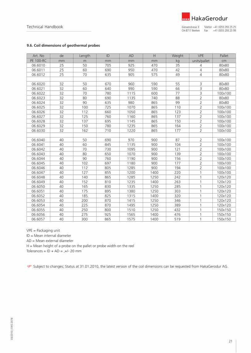
9.6. Coil dimensions of geothermal probes
Art. No de Length ID AD H Weight VPE PalletPE 100-RC mm m mm mm mm kg units/pallet cm06.6010 25 50 705 925 470 35 4 80x8006.6011 25 60 690 950 470 42 4 80x8006.6012 25 70 635 905 575 49 4 80x80
06.6020 32 50 670 960 590 55 3 80x8006.6021 32 60 640 990 590 66 3 80x8006.6022 32 70 780 1115 600 77 3 100x10006.6023 32 80 690 1135 740 88 2 80x8006.6024 32 90 635 980 865 99 2 80x8006.6025 32 100 725 1070 865 110 2 100x10006.6026 32 112 660 1050 865 123 2 100x10006.6027 32 125 760 1160 865 137 2 100x10006.6028 32 137 695 1145 865 150 2 100x10006.6029 32 150 780 1235 865 164 2 100x10006.6030 32 162 710 1220 865 177 2 100x100
06.6040 40 50 690 970 900 87 2 100x10006.6041 40 60 845 1135 900 104 2 100x10006.6042 40 70 730 1095 900 121 2 100x10006.6043 40 80 650 1070 900 139 2 100x10006.6044 40 90 760 1190 900 156 2 100x10006.6045 40 102 697 1180 900 177 2 100x10006.6046 40 112 805 1285 900 194 2 100x10006.6047 40 127 855 1200 1400 220 1 100x10006.6048 40 140 865 1285 1250 242 1 120x12006.6049 40 152 810 1235 1400 263 1 120x12006.6050 40 165 830 1335 1250 285 1 120x12006.6051 40 175 895 1380 1250 303 1 120x12006.6052 40 185 825 1315 1400 320 1 120x12006.6053 40 200 870 1415 1250 346 1 120x12006.6054 40 225 870 1495 1250 389 1 120x12006.6055 40 250 800 1510 1250 432 1 150x15006.6056 40 275 925 1565 1400 476 1 150x15006.6057 40 300 865 1575 1400 519 1 150x150
VPE = Packaging unitID = Mean internal diameterAD = Mean external diameterH = Mean height of a probe on the pallet or probe width on the reelTolerances = ID + AD = ‚+/- 20 mm
Subject to changes; Status at 31.01.2010, the latest version of the coil dimensions can be requested from HakaGerodur AG.
03/2
010
| EW
S-20
78
22
HakaGerodurGiessenstrasse 3 Telefon +41 (0)55 293 25 25CH-8717 Benken Fax +41 (0)55 293 25 99
Technical Handbook
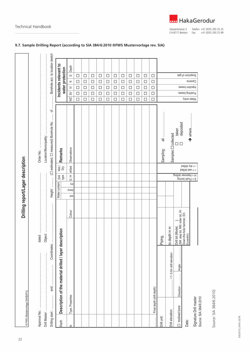
9.7. Sample Drilling Report (according to SIA 384/6:2010 ©FWS Mustervorlage rev. SIA)
©FW
S(M
uster
vorla
geSI
A/BA
FU)
Drilli
ngre
port/
Lage
rdes
crip
tion
Appr
oval
No.:
........
........
........
........
........
........
........
........
.....
dated
:.....
........
........
........
........
........
........
........
........
......
Orde
rNo.:
........
........
........
........
........
........
........
........
........
........
........
........
........
........
......
Drill
Maste
r:....
........
........
........
........
........
........
........
........
....Ob
ject:
........
........
........
........
........
........
........
........
........
..Lo
catio
n/Mun
icipa
lity:.
........
........
........
........
........
........
........
........
........
........
........
........
....Dr
illing
start
:.....
........
....en
d:....
........
........
.....
Coor
dinate
s:....
........
........
........
........
........
.....
Heigh
t:....
........
(es
timate
d,
meas
ured
)Bor
ehole
No..
.......
of....
........
.....B
oreh
oleac
c.to
locat
ionsk
etch
Wate
rcon
tent
Depth
Desc
riptio
nof
them
ater
ialdr
illed
/laye
rdes
crip
tion
Drill
type
Wet
/Dr
yRe
mar
ksIn
ciden
tsre
levan
tto
wate
rpro
tect
ion
toTy
pe,P
rope
rties
Colou
r
wet
damp
dry
S/H
drille
dOb
serva
tions
WZ
SVIV
KG
Depth
……
…..
Final
depth
(drill
depth
)
Drill
unit:
Pipin
g,Æ
Samp
ling:
all....
........
........
........
.
Drill
eleva
tion:
........
........
........
+“/-
0.0m
drill
eleva
tion
tode
pthin
m
Inc
lined
bore
:Di
recti
on:..
........
......
Angle
:......
........
........
Date:
Drill
bit(M
odel,
Æ):
(SM:
stepb
it,RM
:roll
erbit
,IH:
Down
-the-
hole
hamm
er,E
X:Ec
centr
ic)
Sign
ature
Drill
maste
r
S=FlushboringH=Hammerdrilling~=wetdrilled-=drydrilled
Samp
les:
colle
cted
tak
en
depo
sited
wh
ere..
........
.......
Waterentry
Flushinglosses
Injectionlosses
Caverns
Suspicionofgas
Sour
ce:S
IA38
4/6:20
10
Sour
ce: S
IA 3
84/6
:201
0)

23
03/2
010
| EW
S-20
78
HakaGerodurGiessenstrasse 3 Telefon +41 (0)55 293 25 25CH-8717 Benken Fax +41 (0)55 293 25 99
Technical Handbook
9.8. Sample Test and Acceptance Report (according to SIA 384/6:2010)
Object: Order No. :Geothermal probes No.
Factory Identification Number ID:
Roll pair number (e.g. 0040) No.
Length (integrated probe) m
External diameter / Wall thickness mm / / /Flow check Test date
KL1/KL2 KL1 KL2 KL1/KL2 KL1 KL2 KL1/KL2 KL1 KL2Water flow volume l / minPressure during flow barCondition met? Yes / NoLeakage test Test dateacc. to SIA 384/6 (based on SN EN 805) Set value Actual value Set value Actual value Set value Actual valueRead-out accuracy 0.01 bar KL1/KL2 KL 1 KL2 KL1/KL2 KL1 KL2 KL1/KL2 KL1 KL2
Sequence Test pressure procedure for: barin minutes (Dependent on the length of the EWS and the
density of the back-filling; see SIA 384/2 AppendixB2 Tab. 4)Filling probe with water
0 Apply test pressure bar10 Pressure at end of pressure
maintenancebar
60 End of static pressure drop bar(perm. pressure drop acc. to manufacturer)Pressure after pressurereduction bar(Reduction 10% of the test pressure, min.1 bar)Quantity of drained water l(acc. to SIA 384/6, Appendix B2, Tab. 5)
65 Pressure read out bar75 Pressure read out bar90 Pressure at end of main test bar
Condition met: Yes / NoBack-filling Standard: 100 kg Bentonit, 200 kg
cement, 900 l water DateBentonit Cement Water Bentonit Cement Water Bentonit Cement Water
Quantity in kg Bentonit, cement, wateror ready-mix: manufacturer, water/100 kgTotal quantity of back-filling in kg / spec. gravity inkg/m3
yes/no Metre UK Terrain yes/no Metre UK Terrain yes/no Metre UK Terrain
Until UKT met, Yes, if NI up to Metre UKTAcceptance SIA Norm 118 Polish:Place and date: Construction manager:
Source: SIA 384/6:2010

03/2
010
| EW
S-20
78
24
HakaGerodurGiessenstrasse 3 Telefon +41 (0)55 293 25 25CH-8717 Benken Fax +41 (0)55 293 25 99
Technical Handbook
Sour
ce: V
KR,
Ver
band
Kun
stst
off-
Rohr
e an
d Ro
hrle
itung
stei
le (A
ssoc
iatio
n fo
r Pl
astic
Pip
es a
nd P
last
ic P
ipe
Com
pone
nts,
500
0 A
arau
, Sw
itzer
land
9.9. Sample report for the heated-coil welding of pipelines
W
eldi
ng a
nd la
ying
of p
ipel
ines
from
PE
laid
end
-to-e
nd
VKR
7. H
eate
d –c
oil w
eldi
ng
Wel
ding
Rep
ort
for e
lect
rofu
sion
(hea
ted
–coi
l wel
ding
)
PE
100
Bui
ldin
g ow
ner
Com
pany
car
ryin
g ou
t th
e w
ork
Wel
ding
uni
t *W
eath
er
*Con
stru
ctio
n si
te
prot
ectio
n
su
nny
1 N
one
1
dr
y 2
Scr
een
2
ra
in
3 Te
nt
3
Obj
ect
Wel
der
Man
ufac
ture
H
eate
d 4
No.
D
ate
Pipe
Ø
Serie
s/SD
R
Ohm
ΩVo
lt (s
ec.
volta
ge)
Res
ista
nce
Wel
ding
tim
eC
oolin
g tim
e Te
mpe
ratu
re*W
eath
er
*Con
stru
ctio
n si
te
prot
ectio
n M
ains
op
erat
ion
Gen
erat
orSi
gnat
ure
fitte
r
Cop
yrig
ht b
y V
KR
, Ver
band
Kun
stst
off-R
ohre
and
–R
ohrle
itung
stei
le
(1
1.09
)
A 7
.2
HakaGerodur AGMooswiesstrasse 67PostfachCH-9200 Gossau SGTelefon +41 (0)71 388 94 94Fax +41 (0)71 388 94 [email protected]
HakaGerodur AGGiessenstrasse 3PostfachCH-8717 Benken SGTelefon +41 (0)55 293 25 25Fax +41 (0)55 293 25 [email protected]
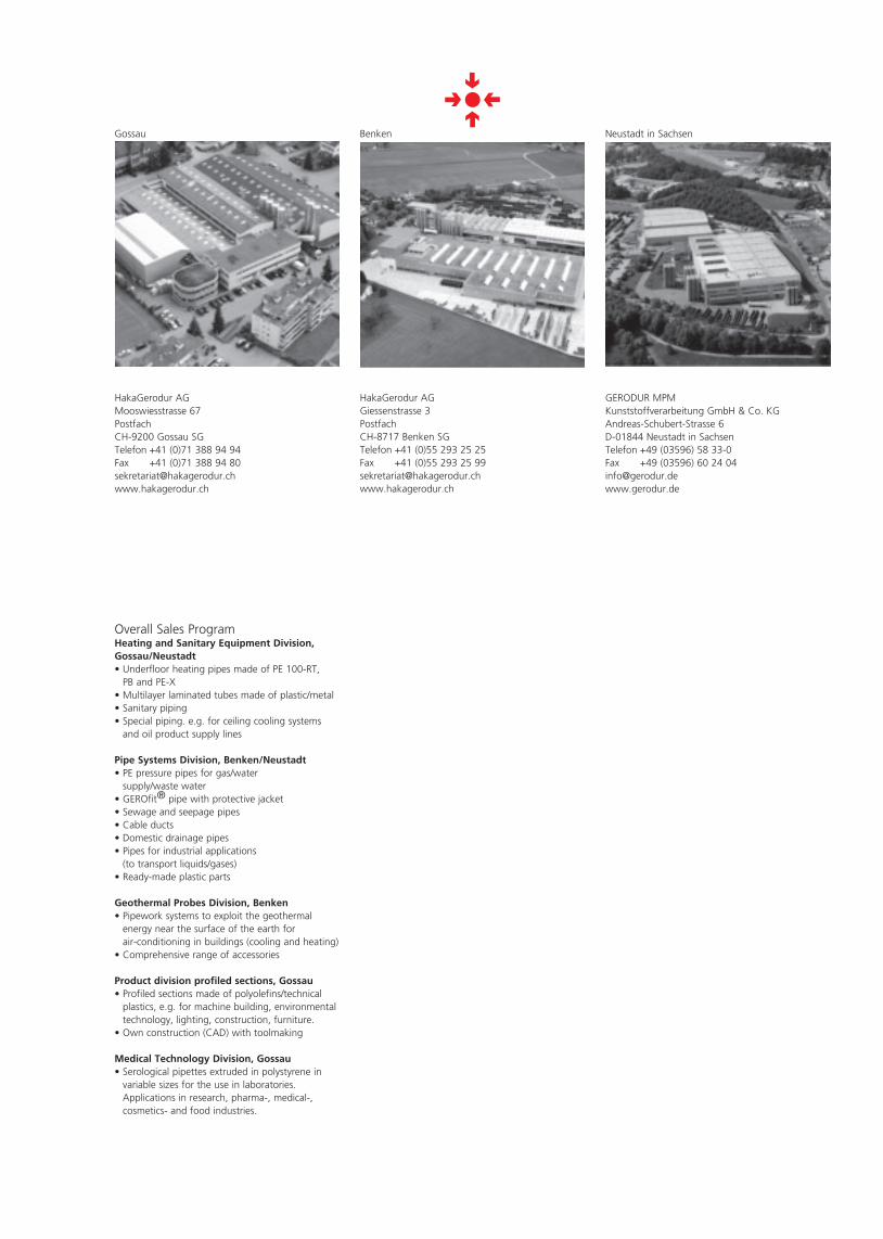
Gossau Benken Neustadt in Sachsen
GERODUR MPMKunststoffverarbeitung GmbH & Co. KGAndreas-Schubert-Strasse 6D-01844 Neustadt in SachsenTelefon +49 (03596) 58 33-0Fax +49 (03596) 60 24 [email protected]
Overall Sales ProgramHeating and Sanitary Equipment Division,Gossau/Neustadt• Underfloor heating pipes made of PE 100-RT,
PB and PE-X• Multilayer laminated tubes made of plastic/metal • Sanitary piping• Special piping. e.g. for ceiling cooling systems
and oil product supply lines
Pipe Systems Division, Benken/Neustadt• PE pressure pipes for gas/water
supply/waste water• GEROfit® pipe with protective jacket• Sewage and seepage pipes• Cable ducts• Domestic drainage pipes• Pipes for industrial applications
(to transport liquids/gases)• Ready-made plastic parts
Geothermal Probes Division, Benken• Pipework systems to exploit the geothermal
energy near the surface of the earth for air-conditioning in buildings (cooling and heating)
• Comprehensive range of accessories
Product division profiled sections, Gossau• Profiled sections made of polyolefins/technical plastics, e.g. for machine building, environmental technology, lighting, construction, furniture.• Own construction (CAD) with toolmaking
Medical Technology Division, Gossau• Serological pipettes extruded in polystyrene in variable sizes for the use in laboratories. Applications in research, pharma-, medical-, cosmetics- and food industries.

03/2
010
| EW
S-20
78