Embed Size (px)
Citation preview

High Availability ClusterMulti-Processing for AIX
Planning GuideVersion 4.5
SC23-4277-04


Fifth Edition (June 2002)Before using the information in this book, read the general information in Notices for HACMP Planning Guide.
This edition applies to HACMP for AIX, version 4.5 and to all subsequent releases of this product until otherwise indicated in new editions.
© Copyright International Business Machines Corporation 1998, 2002. All rights reserved.
Note to U.S. Government Users Restricted Rights--Use, duplication or disclosure restricted by GSA ADP Schedule Contract with IBM Corp.

Contents
About This Guide 11
Chapter 1: Planning an HACMP Cluster: Overview 15Design Goal: Eliminating Single Points of Failure . . . . . . . . . . . . . . . . . .15
Eliminating Cluster Objects as Single Points of Failure . . . . . . . . . . . . . . . . .16Cluster Planning Worksheets. . . . . . . . . . . . . . . . . . . . . . . . . . . . . . . . . . .17
Paper Worksheets . . . . . . . . . . . . . . . . . . . . . . . . . . . . . . . . . . . . . . . . . . . . . .17Online Worksheets . . . . . . . . . . . . . . . . . . . . . . . . . . . . . . . . . . . . . . . . . . . . .17
The Planning Process. . . . . . . . . . . . . . . . . . . . . . . . . . . . . . . . . . . . . . . . .17Step 1: Draw a Cluster Diagram . . . . . . . . . . . . . . . . . . . . . . . . . . . . . . . . . . .18Step 2: Plan Your TCP/IP Networks. . . . . . . . . . . . . . . . . . . . . . . . . . . . . . . .18Step 3: Plan Your Serial Networks . . . . . . . . . . . . . . . . . . . . . . . . . . . . . . . . .18Step 4: Plan Your Shared Disk Devices . . . . . . . . . . . . . . . . . . . . . . . . . . . . .18Step 5: Plan Your Shared LVM Components . . . . . . . . . . . . . . . . . . . . . . . . .18Step 6: Plan Your Application Servers and Resource Groups . . . . . . . . . . . .18Step 7: Tailor the Cluster Event Processing . . . . . . . . . . . . . . . . . . . . . . . . . .18Step 8: Plan Your HACMP Clients. . . . . . . . . . . . . . . . . . . . . . . . . . . . . . . . .18Step 9: Install and Configure Your HACMP Cluster . . . . . . . . . . . . . . . . . . .19
Chapter 2: Drawing the Cluster Diagram 21Prerequisites. . . . . . . . . . . . . . . . . . . . . . . . . . . . . . . . . . . . . . . . . . . . . . . .21Overview . . . . . . . . . . . . . . . . . . . . . . . . . . . . . . . . . . . . . . . . . . . . . . . . . .21Starting the Cluster Diagram . . . . . . . . . . . . . . . . . . . . . . . . . . . . . . . . . . .21
Naming the Cluster . . . . . . . . . . . . . . . . . . . . . . . . . . . . . . . . . . . . . . . . . . . . .23Identifying the Highly Available Applications and Resource Types . . . . . . .23Selecting the Number of Nodes . . . . . . . . . . . . . . . . . . . . . . . . . . . . . . . . . . .24Assigning Cluster IP Addresses . . . . . . . . . . . . . . . . . . . . . . . . . . . . . . . . . . .25Selecting the Method of Shared Disk Access . . . . . . . . . . . . . . . . . . . . . . . . .25
Chapter 3: Planning TCP/IP Networks 27Prerequisites. . . . . . . . . . . . . . . . . . . . . . . . . . . . . . . . . . . . . . . . . . . . . . . .27Overview . . . . . . . . . . . . . . . . . . . . . . . . . . . . . . . . . . . . . . . . . . . . . . . . . .27General Network Requirements for HACMP . . . . . . . . . . . . . . . . . . . . . .27
General Network Connection Example. . . . . . . . . . . . . . . . . . . . . . . . . . . . . .28Considerations for HACMP Configuration in Switched Networks . . . . . . . .28
Selecting Public and Private Networks . . . . . . . . . . . . . . . . . . . . . . . . . . .29Private Network Preferred for Cluster Lock Manager Traffic . . . . . . . . . . . .29
Planning Guide 5

Contents
6
Designing a Network Topology . . . . . . . . . . . . . . . . . . . . . . . . . . . . . . . .29Sample Network Topologies . . . . . . . . . . . . . . . . . . . . . . . . . . . . . . . . . . . . . .30Single Network . . . . . . . . . . . . . . . . . . . . . . . . . . . . . . . . . . . . . . . . . . . . . . . .30Dual Network . . . . . . . . . . . . . . . . . . . . . . . . . . . . . . . . . . . . . . . . . . . . . . . . .30Point-to-Point Connection . . . . . . . . . . . . . . . . . . . . . . . . . . . . . . . . . . . . . . .31
Identifying Network Components . . . . . . . . . . . . . . . . . . . . . . . . . . . . . . .32Nodes. . . . . . . . . . . . . . . . . . . . . . . . . . . . . . . . . . . . . . . . . . . . . . . . . . . . . . . .32Network Adapters . . . . . . . . . . . . . . . . . . . . . . . . . . . . . . . . . . . . . . . . . . . . . .33Network Interfaces . . . . . . . . . . . . . . . . . . . . . . . . . . . . . . . . . . . . . . . . . . . . .36Networks . . . . . . . . . . . . . . . . . . . . . . . . . . . . . . . . . . . . . . . . . . . . . . . . . . . . .37Defining a Network Mask . . . . . . . . . . . . . . . . . . . . . . . . . . . . . . . . . . . . . . .38
Defining IP Addresses for Standby Adapters . . . . . . . . . . . . . . . . . . . . .38Placing Standby Adapters on a Separate Subnet . . . . . . . . . . . . . . . . . . . . . .39
Defining Boot Addresses . . . . . . . . . . . . . . . . . . . . . . . . . . . . . . . . . . . . .40Boot/Service/Standby Address Requirements for Resource Groups . . . . . . .41
Defining Hardware Addresses. . . . . . . . . . . . . . . . . . . . . . . . . . . . . . . . . .42Selecting an Alternate Hardware Address. . . . . . . . . . . . . . . . . . . . . . . . . . . .43Avoiding Network Conflicts . . . . . . . . . . . . . . . . . . . . . . . . . . . . . . . . . . . . . .46
Using HACMP with NIS and DNS . . . . . . . . . . . . . . . . . . . . . . . . . . . . . .47How HACMP Enables and Disables Nameserving . . . . . . . . . . . . . . . . . . . .47
Planning for Cluster Performance . . . . . . . . . . . . . . . . . . . . . . . . . . . . . . .49Setting I/O Pacing . . . . . . . . . . . . . . . . . . . . . . . . . . . . . . . . . . . . . . . . . . . . . .50Setting Syncd Frequency. . . . . . . . . . . . . . . . . . . . . . . . . . . . . . . . . . . . . . . . .51Setting Failure Detection Parameters . . . . . . . . . . . . . . . . . . . . . . . . . . . . . . .51
Adding the TCP/IP Network Topology to the Cluster Diagram . . . . . . . .53Completing the TCP/IP Networks Worksheets . . . . . . . . . . . . . . . . . . . . .54
Completing the TCP/IP Networks Worksheet . . . . . . . . . . . . . . . . . . . . . . .54Completing the TCP/IP Network Adapter Worksheet . . . . . . . . . . . . . . . . . .54
Where You Go From Here . . . . . . . . . . . . . . . . . . . . . . . . . . . . . . . . . . . .55
Chapter 4: Planning Serial Networks 57Prerequisites. . . . . . . . . . . . . . . . . . . . . . . . . . . . . . . . . . . . . . . . . . . . . . . .57Overview . . . . . . . . . . . . . . . . . . . . . . . . . . . . . . . . . . . . . . . . . . . . . . . . . .57Node Isolation and Partitioned Clusters . . . . . . . . . . . . . . . . . . . . . . . . . .57Serial Network Topology . . . . . . . . . . . . . . . . . . . . . . . . . . . . . . . . . . . . .58
Supported Serial Network Types . . . . . . . . . . . . . . . . . . . . . . . . . . . . . . . . . .58Planning HACMP Serial Networks over Longer Distances . . . . . . . . . . .60Adding the Serial Network Topology to the Cluster Diagram . . . . . . . . .60Completing Serial Networks and Serial Network Adapter Worksheets . .61
Completing the Serial Networks Worksheet . . . . . . . . . . . . . . . . . . . . . . . . . .61Completing the Serial Network Adapter Worksheet. . . . . . . . . . . . . . . . . . . .62
Where You Go From Here . . . . . . . . . . . . . . . . . . . . . . . . . . . . . . . . . . . .62
Planning Guide

Contents
Chapter 5: Planning Shared Disk and Tape Devices 63Prerequisites. . . . . . . . . . . . . . . . . . . . . . . . . . . . . . . . . . . . . . . . . . . . . . . .63Overview . . . . . . . . . . . . . . . . . . . . . . . . . . . . . . . . . . . . . . . . . . . . . . . . . .63Choosing a Shared Disk Technology . . . . . . . . . . . . . . . . . . . . . . . . . . . .63
SCSI Disks . . . . . . . . . . . . . . . . . . . . . . . . . . . . . . . . . . . . . . . . . . . . . . . . . . .64IBM Serial Storage Architecture Disk Subsystem . . . . . . . . . . . . . . . . . . . . .67
Power Supply Considerations . . . . . . . . . . . . . . . . . . . . . . . . . . . . . . . . . .68SCSI Power Considerations . . . . . . . . . . . . . . . . . . . . . . . . . . . . . . . . . . . . . .68IBM SSA Disk Subsystem Power Considerations . . . . . . . . . . . . . . . . . . . . .68
Planning for Non-Shared Disk Storage . . . . . . . . . . . . . . . . . . . . . . . . . . .68Planning for Shared Disk Storage . . . . . . . . . . . . . . . . . . . . . . . . . . . . . . .70Planning a Shared SCSI-2 Disk Installation . . . . . . . . . . . . . . . . . . . . . . .71
Disk Adapters . . . . . . . . . . . . . . . . . . . . . . . . . . . . . . . . . . . . . . . . . . . . . . . . .71Cables . . . . . . . . . . . . . . . . . . . . . . . . . . . . . . . . . . . . . . . . . . . . . . . . . . . . . . .71Sample SCSI-2 Differential Configuration . . . . . . . . . . . . . . . . . . . . . . . . . . .72Sample SCSI-2 Differential Fast/Wide Configuration . . . . . . . . . . . . . . . . . .72Sample IBM 7135-210 RAIDiant Disk Array Configuration . . . . . . . . . . . . .73Sample IBM 2105 Versatile Storage Server Configuration . . . . . . . . . . . . . .75
Planning a Shared IBM SSA Disk Subsystem Installation . . . . . . . . . . . .76IBM Manuals for SSA. . . . . . . . . . . . . . . . . . . . . . . . . . . . . . . . . . . . . . . . . . .76SSA Adapters . . . . . . . . . . . . . . . . . . . . . . . . . . . . . . . . . . . . . . . . . . . . . . . . .76Bypass Cards in the 7133, Models 020 and 600 Disk Subsystems. . . . . . . . .77Using SSA Features for High Availability . . . . . . . . . . . . . . . . . . . . . . . . . . .77Configuring to Minimize Single Points of Failure . . . . . . . . . . . . . . . . . . . . .78Configuring for Optimal Performance . . . . . . . . . . . . . . . . . . . . . . . . . . . . . .78
SSA Disk Fencing in Concurrent Access Clusters . . . . . . . . . . . . . . . . . .79Completing the Disk Worksheets . . . . . . . . . . . . . . . . . . . . . . . . . . . . . . .82
Completing the Shared SCSI-2 Disk Worksheet . . . . . . . . . . . . . . . . . . . . . .82Completing the Shared SCSI-2 Disk Array Worksheet . . . . . . . . . . . . . . . . .82Completing the IBM SSA Disk Subsystems Worksheet. . . . . . . . . . . . . . . . .82
Adding the Disk Configuration to the Cluster Diagram . . . . . . . . . . . . . .83Planning for Tape Drives as Cluster Resources . . . . . . . . . . . . . . . . . . . .83
Limitations. . . . . . . . . . . . . . . . . . . . . . . . . . . . . . . . . . . . . . . . . . . . . . . . . . . .83Reserving and Releasing Shared Tape Drives . . . . . . . . . . . . . . . . . . . . . . . .84Recovery Procedures. . . . . . . . . . . . . . . . . . . . . . . . . . . . . . . . . . . . . . . . . . . .84Completing the Shared Tape Drive Worksheet. . . . . . . . . . . . . . . . . . . . . . . .85
Where You Go From Here . . . . . . . . . . . . . . . . . . . . . . . . . . . . . . . . . . . .85
Chapter 6: Planning Shared LVM Components 87Prerequisites. . . . . . . . . . . . . . . . . . . . . . . . . . . . . . . . . . . . . . . . . . . . . . . .87Overview . . . . . . . . . . . . . . . . . . . . . . . . . . . . . . . . . . . . . . . . . . . . . . . . . .87
Planning for Non-Concurrent Access . . . . . . . . . . . . . . . . . . . . . . . . . . . . . . .87Planning for Concurrent Access . . . . . . . . . . . . . . . . . . . . . . . . . . . . . . . . . . .88
Planning Guide 7

Contents
8
LVM Components in the HACMP Environment . . . . . . . . . . . . . . . . . . .88Physical Volumes . . . . . . . . . . . . . . . . . . . . . . . . . . . . . . . . . . . . . . . . . . . . . .88Volume Groups . . . . . . . . . . . . . . . . . . . . . . . . . . . . . . . . . . . . . . . . . . . . . . . .89Logical Volumes . . . . . . . . . . . . . . . . . . . . . . . . . . . . . . . . . . . . . . . . . . . . . . .90Filesystems . . . . . . . . . . . . . . . . . . . . . . . . . . . . . . . . . . . . . . . . . . . . . . . . . . .90
LVM Mirroring . . . . . . . . . . . . . . . . . . . . . . . . . . . . . . . . . . . . . . . . . . . . .90Mirroring Physical Partitions . . . . . . . . . . . . . . . . . . . . . . . . . . . . . . . . . . . . .91Mirroring Journal Logs . . . . . . . . . . . . . . . . . . . . . . . . . . . . . . . . . . . . . . . . . .92
Quorum . . . . . . . . . . . . . . . . . . . . . . . . . . . . . . . . . . . . . . . . . . . . . . . . . . .92Quorum at Vary On. . . . . . . . . . . . . . . . . . . . . . . . . . . . . . . . . . . . . . . . . . . . .93Quorum after Vary On . . . . . . . . . . . . . . . . . . . . . . . . . . . . . . . . . . . . . . . . . .93Disabling and Enabling Quorum. . . . . . . . . . . . . . . . . . . . . . . . . . . . . . . . . . .93Quorum in Non-Concurrent Access Configurations . . . . . . . . . . . . . . . . . . . .94Quorum in Concurrent Access Configurations . . . . . . . . . . . . . . . . . . . . . . . .95
Using NFS with HACMP . . . . . . . . . . . . . . . . . . . . . . . . . . . . . . . . . . . . .96Reliable NFS Server Capability . . . . . . . . . . . . . . . . . . . . . . . . . . . . . . . . . . .96Creating Shared Volume Groups with NFS . . . . . . . . . . . . . . . . . . . . . . . . . .96NFS-Exporting Filesystems and Directories. . . . . . . . . . . . . . . . . . . . . . . . . .97Cascading Takeover with Cross Mounted NFS Filesystems . . . . . . . . . . . . .97
LVM Planning Summary and Additional Notes . . . . . . . . . . . . . . . . . . .100Completing the Shared LVM Components Worksheets . . . . . . . . . . . . .101
Non-Concurrent Access Worksheets. . . . . . . . . . . . . . . . . . . . . . . . . . . . . . .101Concurrent Access Worksheets. . . . . . . . . . . . . . . . . . . . . . . . . . . . . . . . . . .103
Where You Go From Here . . . . . . . . . . . . . . . . . . . . . . . . . . . . . . . . . . .104
Chapter 7: Planning Applications, Application Servers, and Resource Groups 105
Prerequisites. . . . . . . . . . . . . . . . . . . . . . . . . . . . . . . . . . . . . . . . . . . . . . .105Overview . . . . . . . . . . . . . . . . . . . . . . . . . . . . . . . . . . . . . . . . . . . . . . . . .105
Application Servers . . . . . . . . . . . . . . . . . . . . . . . . . . . . . . . . . . . . . . . . . . . .105Some Applications are Integrated with HACMP . . . . . . . . . . . . . . . . . . . . .106
Planning Applications and Application Servers . . . . . . . . . . . . . . . . . . .106Completing the Application Worksheet . . . . . . . . . . . . . . . . . . . . . . . . . . . .107Completing the Application Server Worksheet. . . . . . . . . . . . . . . . . . . . . . .108
Planning for AIX Fast Connect . . . . . . . . . . . . . . . . . . . . . . . . . . . . . . . .108Converting from AIX Connections to AIX Fast Connect . . . . . . . . . . . . . . .109Planning Considerations for Fast Connect . . . . . . . . . . . . . . . . . . . . . . . . . .109Fast Connect as a Highly Available Resource . . . . . . . . . . . . . . . . . . . . . . .110Completing the Fast Connect Worksheet . . . . . . . . . . . . . . . . . . . . . . . . . . .110
Planning for AIX Connections . . . . . . . . . . . . . . . . . . . . . . . . . . . . . . . .111AIX Connections Realms and Services. . . . . . . . . . . . . . . . . . . . . . . . . . . . .111Planning Notes for AIX Connections . . . . . . . . . . . . . . . . . . . . . . . . . . . . . .111AIX Connections as a Highly Available Resource . . . . . . . . . . . . . . . . . . . .111Completing the AIX Connections Worksheet. . . . . . . . . . . . . . . . . . . . . . . .112
Planning Guide

Contents
Planning for Workload Manager . . . . . . . . . . . . . . . . . . . . . . . . . . . . . . .113About Workload Manager Classes . . . . . . . . . . . . . . . . . . . . . . . . . . . . . . . .113Reconfiguration, Startup, and Shutdown of Workload Manager . . . . . . . . .114Limitations and Considerations. . . . . . . . . . . . . . . . . . . . . . . . . . . . . . . . . . .114Assigning Workload Manager Classes to HACMP Resource Groups . . . . .115
Planning for Highly Available Communication Links . . . . . . . . . . . . . .115Required Software and Hardware . . . . . . . . . . . . . . . . . . . . . . . . . . . . . . . . .115Completing the Communication Links Worksheets . . . . . . . . . . . . . . . . . . .116
Planning Resource Groups . . . . . . . . . . . . . . . . . . . . . . . . . . . . . . . . . . .118Guidelines . . . . . . . . . . . . . . . . . . . . . . . . . . . . . . . . . . . . . . . . . . . . . . . . . . .118
Completing the Resource Group Worksheet . . . . . . . . . . . . . . . . . . . . . .123Where You Go From Here . . . . . . . . . . . . . . . . . . . . . . . . . . . . . . . . . . .126
Chapter 8: Tailoring Cluster Event Processing 127Prerequisites. . . . . . . . . . . . . . . . . . . . . . . . . . . . . . . . . . . . . . . . . . . . . . .127Overview . . . . . . . . . . . . . . . . . . . . . . . . . . . . . . . . . . . . . . . . . . . . . . . . .127Customizing Cluster Event Processing . . . . . . . . . . . . . . . . . . . . . . . . . .127
Event Notification . . . . . . . . . . . . . . . . . . . . . . . . . . . . . . . . . . . . . . . . . . . . .128Pre- and Post-Event Scripts . . . . . . . . . . . . . . . . . . . . . . . . . . . . . . . . . . . . .128Event Recovery and Retry. . . . . . . . . . . . . . . . . . . . . . . . . . . . . . . . . . . . . . .129
Customizing Event Duration Time Until Warning . . . . . . . . . . . . . . . . .129Planning Event Duration Time Before Warning. . . . . . . . . . . . . . . . . . . . . .129
Custom Pager Notification . . . . . . . . . . . . . . . . . . . . . . . . . . . . . . . . . . .130Planning for Custom Pager Notification . . . . . . . . . . . . . . . . . . . . . . . . . . . .130
Completing the Cluster Event Worksheet . . . . . . . . . . . . . . . . . . . . . . . .131Where You Go From Here . . . . . . . . . . . . . . . . . . . . . . . . . . . . . . . . . . .131
Chapter 9: Planning HACMP Clients 133Prerequisites. . . . . . . . . . . . . . . . . . . . . . . . . . . . . . . . . . . . . . . . . . . . . . .133Overview . . . . . . . . . . . . . . . . . . . . . . . . . . . . . . . . . . . . . . . . . . . . . . . . .133Different Types of Clients: Computers and Terminal Servers . . . . . . . .133
Client Application Systems . . . . . . . . . . . . . . . . . . . . . . . . . . . . . . . . . . . . . .133NFS Servers. . . . . . . . . . . . . . . . . . . . . . . . . . . . . . . . . . . . . . . . . . . . . . . . . .133Terminal Servers . . . . . . . . . . . . . . . . . . . . . . . . . . . . . . . . . . . . . . . . . . . . . .133
Clients Running Clinfo . . . . . . . . . . . . . . . . . . . . . . . . . . . . . . . . . . . . . .134Reconnecting to the Cluster . . . . . . . . . . . . . . . . . . . . . . . . . . . . . . . . . . . . .134Tailoring the clinfo.rc Script . . . . . . . . . . . . . . . . . . . . . . . . . . . . . . . . . . . . .134
Network Components and Clients Not Running Clinfo . . . . . . . . . . . . .134Where You Go From Here . . . . . . . . . . . . . . . . . . . . . . . . . . . . . . . . . . .135
Planning Guide 9

Contents
10
Appendix A: Planning Worksheets 137
Appendix B: Using the Online Planning Worksheet Program 187
Appendix C: Single-Adapter Networks 197
Appendix D: Applications and HACMP 199
Index 209
Planning Guide
About This GuideThis guide presents information necessary to plan an HACMP cluster.
Who Should Use This GuideThis guide is intended for system administrators, network administrators, and customer engineers responsible for:• Planning hardware and software resources for an HACMP environment• Configuring networks• Defining physical and logical storage• Installing and configuring an HACMP cluster.
Before You BeginAs a prerequisite for planning your HACMP cluster, you should be familiar with:• IBM RS/6000 components (including disk devices, cabling, and network adapters for each
system). HACMP, Version 4.5 runs on RS/6000 uniprocessor systems, RS/6000 SP systems, and PowerPC Symmetric Multiprocessors (SMP).
• The AIX operating system, including the Logical Volume Manager subsystem.• The System Management Interface Tool (SMIT).• Communications, including the TCP/IP subsystem.
This guide explains the preceding topics as they relate to the HACMP software. Prior knowledge of these topics can aid you in planning, installing, and configuring an HACMP cluster.
Using the Planning WorksheetsAppendix A contains blank copies of the worksheets used in this guide. These worksheets help you plan, install, and track an HACMP cluster. Make copies of each worksheet and keep the blank originals in this book. The worksheets are especially useful when making modifications and performing diagnostics.
Alternatively, you can use the java-based online planning worksheets program. See Appendix B: Using the Online Planning Worksheet Program for information.
Additionally, you will benefit from creating diagrams of your cluster.
Planning Guide 11

12
HighlightingThe following highlighting conventions are used in this book:
ISO 9000ISO 9000 registered quality systems were used in the development and manufacturing of this product.
Related PublicationsThe following publications provide additional information about the HACMP software:• Release Notes in /usr/lpp/cluster/doc/release_notes describe hardware and software
requirements• Concepts and Facilities Guide - SC23-4276• Installation Guide - SC23-4278• Administration Guide - SC23-4279• Troubleshooting Guide - SC23-4280• Programming Locking Applications - SC23-4281• Programming Client Applications - SC23-4282• Enhanced Scalability Installation and Administration Guide - SC23-4284• Master Glossary - SC23-4285• IBM International Program License Agreement
In addition, the manuals accompanying your machine and disk hardware also provide relevant information.
Accessing IBM PublicationsOn the World Wide Web, enter the following URL to access an online library of documentation covering AIX, RS/6000, and related products:
http://www-1.ibm.com/servers/aix/library/.
Italic Identifies variables in command syntax, new terms and concepts, or indicates emphasis.
Bold Identifies routines, commands, keywords, files, directories, menu items, and other items whose actual names are predefined by the system.
Monospace Identifies examples of specific data values, examples of text similar to what you might see displayed, examples of program code similar to what you might write as a programmer, messages from the system, or information that you should actually type.
Planning Guide

TrademarksThe following terms are trademarks of International Business Machines Corporation in the United States, other countries, or both:• AFS• AIX • AIX 5L• DFS•
• Enterprise Storage Server• IBM• NetView• pSeries• RS/6000 • Scalable POWERParallel Systems• Shark• SP • xSeries
UNIX is a registered trademark in the United States and other countries and is licensed exclusively through The Open Group.
Other company, product, and service names may be trademarks or service marks of others.
Planning Guide 13

14
Planning Guide
Planning an HACMP Cluster: OverviewDesign Goal: Eliminating Single Points of Failure 1
Chapter 1: Planning an HACMP Cluster: Overview
This chapter provides an overview of the recommended planning process and describes the paper and online cluster planning worksheets.
Design Goal: Eliminating Single Points of FailureThe HACMP software provides numerous facilities you can use to build highly available clusters. Designing the cluster that provides the best solution for your organization requires careful and thoughtful planning. In fact, adequate planning is the key to building a successful HACMP cluster. A well-planned cluster is easier to install, provides higher availability, performs better, and requires less maintenance than a poorly planned cluster.
Your major goal throughout the planning process is to eliminate single points of failure. A single point of failure exists when a critical cluster function is provided by a single component. If that component fails, the cluster has no other way of providing that function, and the service dependent on that component becomes unavailable.
For example, if all the data for a critical application resides on a single disk, and that disk fails, that disk becomes a single point of failure for the entire cluster. Clients cannot access that application until the data on the disk is restored. Likewise, if dynamic application data is stored on internal disks rather than on external disks, it is not possible to recover an application by having another cluster take over the external disks. Therefore, identifying necessary logical components required by an application, such as filesystems and directories (which could contain application data and configuration variables), is an important prerequisite for planning a successful cluster.
Realize that, while your goal is to eliminate all single points of failure, you may have to make some compromises. There is usually a cost associated with eliminating a single point of failure. For example, purchasing an additional hardware device to serve as backup for the primary device increases cost. The cost of eliminating a single point of failure should be compared against the cost of losing services should that component fail. Again, the purpose of the HACMP software is to provide a cost-effective, highly available computing platform that can grow to meet future processing demands.
Important: HACMP is designed to recover from a single hardware or software failure. It may not be able to handle multiple failures, depending on the sequence of failures. For example, the default event scripts cannot do an adapter swap after an IP address takeover (IPAT) has occurred if only one standby adapter exists for that network.
To be highly available, all cluster resources associated with a critical application should have no single points of failure. As you design an HACMP cluster, your goal is to identify and address all potential single points of failure. Questions to ask yourself include:• What services are required to be highly available? What is the priority of these services?• What is the cost of a failure compared to the necessary hardware to eliminate the possibility
of this failure?
Planning Guide 15
Planning an HACMP Cluster: OverviewDesign Goal: Eliminating Single Points of Failure
16
1
• What is the required availability of these services? Do they need to be available 24 hours a day, seven days a week? Or is eight hours a day, five days a week sufficient?
• What could happen to disrupt the availability of these services?• What is the allotted time for replacing a failed resource? What is an acceptable degree of
performance degradation while operating after a failure?• Which failures are detected as cluster events? Which failures need to have custom code
written to detect the failure and trigger a cluster event?• What is the skill level of the group implementing the cluster? And the group maintaining
the cluster?
To plan, implement, and maintain a successful HACMP cluster requires continuing communication among many groups within your organization. Ideally, you should assemble representatives from the following areas (as applicable) to aid in HACMP planning sessions:• Network administration• System administration• Database administration• Application programming• Support• End users.
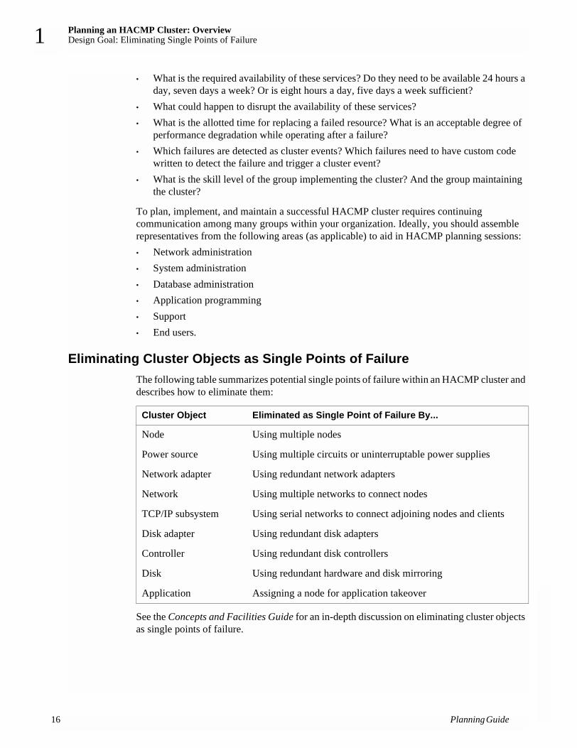
Eliminating Cluster Objects as Single Points of FailureThe following table summarizes potential single points of failure within an HACMP cluster and describes how to eliminate them:
See the Concepts and Facilities Guide for an in-depth discussion on eliminating cluster objects as single points of failure.
Cluster Object Eliminated as Single Point of Failure By...
Node Using multiple nodes
Power source Using multiple circuits or uninterruptable power supplies
Network adapter Using redundant network adapters
Network Using multiple networks to connect nodes
TCP/IP subsystem Using serial networks to connect adjoining nodes and clients
Disk adapter Using redundant disk adapters
Controller Using redundant disk controllers
Disk Using redundant hardware and disk mirroring
Application Assigning a node for application takeover
Planning Guide

Planning an HACMP Cluster: OverviewCluster Planning Worksheets 1
Note: In an HACMP environment on an SP machine, the SP Switch adapter is a single point of failure and should be promoted to node failure. See the appendix on using the SP machine in the Installation Guide for complete information on the SP Switch adapter functionality.
Cluster Planning WorksheetsAt each step of the planning process, you can use planning worksheets to guide and organize your planning for each component of your cluster.
Both paper and online planning worksheets are provided with HACMP.
Paper WorksheetsThe paper worksheets are located in Appendix A: Planning Worksheets. They are organized in the recommended sequence of planning steps. You make copies of these worksheets and write down all details of your cluster components in the appropriate spaces. You then refer to these sheets as you install and configure your cluster.
Paper worksheets can be useful when discussing cluster planning options with your team. They provide a written record of your initial cluster configuration decisions, which can help you trace problems in the future.
Online WorksheetsThe java-based online planning worksheet program allows you to enter your information as you go. After you have completed all of the planning steps, HACMP will automatically apply the configuration.
Like the paper worksheets, the online worksheet panels show the recommended sequence of steps you should take to plan your cluster. The user interface for the online worksheets has a different format than the paper worksheets, for example, in some cases an online panel consolidates information from several paper worksheets. Each worksheet format provides you with a framework to help you organize the appropriate information to configure each part of your cluster.
For instructions on installing and using the online planning worksheets on an AIX or Windows system, see Appendix B: Using the Online Planning Worksheet Program.
The Planning ProcessThis section describes the recommended steps you should follow to plan an HACMP cluster. As you plan a cluster, be aware that you will need to plan for application servers and resource groups within the cluster, and you will need to tailor event processing to allow the cluster to handle special failure situations.
Even if you are using the online planning worksheets, you should go over the information in this guide first, and continue to refer to it as you enter configuration data in the worksheets.
Planning Guide 17

Planning an HACMP Cluster: OverviewThe Planning Process
18
1
Step 1: Draw a Cluster DiagramIn this step you plan the core of the cluster—the applications to be made highly available and the types of resources they require, the number of nodes, shared IP addresses, and a mode for sharing disks (non-concurrent or concurrent access). Your goal is to develop a high-level view of the system that serves as a starting point for the cluster design. In subsequent planning steps you focus on specific subsystems, such as disks and networks. Chapter 2: Drawing the Cluster Diagram provides details on this initial step.
Step 2: Plan Your TCP/IP NetworksIn this step you plan the TCP/IP network support for the cluster. You first examine issues relating to TCP/IP networks in an HACMP environment, and then complete the TCP/IP network worksheets. Chapter 3: Planning TCP/IP Networks, describes this step of the planning process.
Step 3: Plan Your Serial NetworksIn this step you plan the serial network support for the cluster. You first examine issues relating to serial networks in an HACMP environment, and then you complete the serial network worksheets. Chapter 4: Planning Serial Networks, describes this step of the planning process.
Step 4: Plan Your Shared Disk DevicesIn this step you plan the shared disk devices for the cluster. You first examine issues relating to different types of disk arrays and subsystems in an HACMP environment, and then diagram the shared disk configuration. Chapter 5: Planning Shared Disk and Tape Devices, describes this step of the planning process.
Step 5: Plan Your Shared LVM ComponentsIn this step you plan the shared volume groups for the cluster. You first examine issues relating to LVM components in an HACMP environment, and then you fill out worksheets describing physical and logical storage. Chapter 6: Planning Shared LVM Components, describes this step of the planning process.
Step 6: Plan Your Application Servers and Resource GroupsIn this step you plan a cluster around mission-critical applications, listing application server and resource group information specific to your HACMP cluster. Chapter 7: Planning Applications, Application Servers, and Resource Groups, describes this step of the planning process.
Step 7: Tailor the Cluster Event ProcessingIn this step you tailor the event processing for your cluster. Chapter 8: Tailoring Cluster Event Processing, describes this step of the planning process.
Step 8: Plan Your HACMP ClientsIn this step you examine issues relating to HACMP clients. Chapter 9: Planning HACMP Clients, describes this step of the planning process.
Planning Guide

Planning an HACMP Cluster: OverviewThe Planning Process 1
Step 9: Install and Configure Your HACMP ClusterAfter completing the planning steps, you are ready to install the cluster. Use the planning diagrams and worksheets you completed during the planning process to guide you through the installation process.
If you’ve used the online worksheet program, you can create an AIX file to configure your cluster for you. Instructions for this process are in Appendix B: Using the Online Planning Worksheet Program.
Refer to the Installation Guide when installing and configuring your HACMP cluster.
Planning Guide 19

Planning an HACMP Cluster: OverviewThe Planning Process
20
1
Planning Guide

Drawing the Cluster DiagramPrerequisites 2
Chapter 2: Drawing the Cluster DiagramThis chapter describes how to draw a cluster diagram.
PrerequisitesIt is essential that you understand the concepts and terminology necessary in planning an HACMP cluster. Read the Concepts and Facilities Guide before beginning the planning process. The planning steps in this chapter assume a thorough understanding of the information presented in that guide.
OverviewTo develop a robust cluster design, you must progress through a series of steps. In each step, you add a piece to the cluster before moving forward to follow-on steps, which further define the cluster design. At the end of this process, you have designed a cluster that provides a high availability solution tailored to the particular needs of your organization.
In this chapter, you draw a diagram that shows the framework of the cluster. Your goal is to develop a high-level view of the cluster that becomes the starting point for the overall cluster design. In subsequent planning steps, you expand and refine the diagram by focusing on specific subsystems, such as disks and networks.
As you work through the planning process, you will be guided through a series of worksheets to help you organize your configuration information. The worksheets referred to in these chapters are paper worksheets that you fill out by hand and then refer to while configuring your cluster.
You may also use the online cluster planning “worksheets,” the web-based panels that allow you to enter configuration data as you plan, and then configure your cluster from there by creating a file and transferring it from your PC-based system to your AIX cluster nodes. If you plan to use the online worksheets, refer to Appendix B: Using the Online Planning Worksheet Program, for instructions on the installation and use of this program.
Starting the Cluster DiagramThe purpose of the cluster diagram is to combine the information from each step in the planning process into one drawing that shows the cluster’s function and structure. In this section, you make a first pass at drawing the cluster diagram. Remember, this pass is a starting point. You will refine your diagram throughout the planning process.
Note: Even if you are using the online cluster planning worksheet program, in which you enter configuration data as you plan, it is highly recommended that you complete the entire planning process first, including drawing and refining a cluster diagram.
Planning Guide 21

Drawing the Cluster DiagramStarting the Cluster Diagram
22
2
The initial pass of the cluster diagram identifies:• The cluster name and ID • Applications to be made highly available and the types of resources used by the
applications• The number of nodes in the cluster, and their names• IP addresses for the nodes• The method of shared disk access
An example of a first pass at a cluster diagram is shown in the following figure:
A First Pass of a Cluster Diagram
This diagram describes a two-node cluster that makes the Image Cataloger demo (an application supplied with the HACMP software) highly available. One node is named node A; the other node B. The cluster uses cascading resources and shares one external disk accessed by one node at a time.
Complete the following steps to begin the cluster diagram:• Name the cluster and assign it an ID• Identify the highly available applications and resource group types• Select the number of cluster nodes and name them• Determine the IP addresses for client use (optional)• Select the method of shared disk access.
Planning Guide

Drawing the Cluster DiagramStarting the Cluster Diagram 2
Naming the ClusterName the cluster and give it an ID. The cluster name is an arbitrary string of no more than 31 characters, with alphanumeric and underscores only. It cannot have a leading numeric. The cluster ID can be any positive integer less than 99,999.
Important: Make sure that each cluster name and ID you define does not conflict with the names and IDs of other clusters at your site.
As shown in the preceding diagram, the cluster is named bivalves; it has an ID of 1.
Identifying the Highly Available Applications and Resource Types The purpose of the HACMP software is to ensure that critical applications and services are available. This guide presumes you have already identified these applications. For each application, you need to specify the type of resources the application uses, and a resource takeover strategy (based on the access mode chosen for each node).
Some applications are integrated into HACMP and are configured differently than other applications. For information on planning for AIX Connections, AIX Fast Connect, and Workload Manager availability, see Chapter 7: Planning Applications, Application Servers, and Resource Groups.
The HACMP software supports a maximum of up to 20 resource groups per cluster. Three types of resource groups are supported:• Cascading, where a resource may be taken over by one or more nodes in a resource chain
according to the takeover priority assigned to each node. The available node within the cluster with the highest priority will own the resource. You can also choose to set a flag so that a cascading resource will not fall back to a higher priority owner node when that node reintegrates into the cluster.
• Rotating, where a resource is associated with a group of nodes and rotates among these nodes. When a node fails, the next available node on its boot address and listed first in the resource chain will acquire the resource group. The takeover node may be currently active, or it may be in a standby state. When a detached node rejoins the cluster, however, it does not reacquire resource groups; instead, it rejoins as a standby.
• Concurrent access, where a resource that can be managed by the HACMP Cluster Lock Manager may be simultaneously shared among multiple applications residing on different nodes.
Note: The HACMP lock manager is not supported on a 64-bit AIX kernel.
Keep the following considerations in mind when deciding which resource group type to assign to an application:• If maximizing performance is essential, cascading resources may be the best resource
group choice. Using cascading resources ensures that an application is owned by a particular node whenever that node is active in the cluster. This ownership allows the node to cache data the application uses frequently, thereby improving the node’s performance for providing data to the application.• If the active node fails, its resources will be taken over by the node with the highest
priority in the resource chain.
Planning Guide 23

Drawing the Cluster DiagramStarting the Cluster Diagram
24
2
• When the failed node reintegrates into the cluster, it temporarily disrupts application availability as it takes back its resources from the takeover node, unless you have defined the resource groups to use cascading without fallback.
• If minimizing downtime is essential, rotating resources may be the best choice. Application availability is not disrupted during node reintegration because the reintegrating node rejoins the cluster as a standby node only and does not attempt to reacquire its resources.
The Concepts and Facilities Guide provides more information about the various resource group types. It also presents a set of configurations that use different sample types of shared resources. Review these examples for more background on using the different resource group types in an HACMP cluster.
For each node, indicate the applications and their corresponding resource group type on the cluster diagram. Each application can be assigned to only one resource group. A single node, however, can support different resource group types. For applications using cascading resources, also specify the takeover priority for each node. The priority is determined by the order in which the nodes are listed in the resource chain.
For example, the cluster in the previous diagram makes the Image Cataloger application, which uses cascading resources, highly available. The node NodeA has the highest takeover priority in the cluster because its name is listed first in the resource chain. The node NodeB is listed next in the resource chain and therefore is designated as the next cluster node to take over resources in the event of a fallover. In this diagram, the node NodeA is first in the cluster to acquire resources, and the node NodeB is second.
Selecting the Number of Nodes An HACMP cluster can have from two nodes to a maximum of eight nodes. Keep the following considerations in mind when determining the number of nodes in your cluster configuration:• Clusters can have up to eight nodes. The number of nodes that can access a disk subsystem,
however, varies based on the subsystem used. For example, the IBM SSA serial disk drive subsystem can be accessed by up to eight nodes, whereas the IBM 7135-210 RAIDiant Disk Array can be accessed by up to four nodes.
• Reliable NFS server capability that allows a backup processor to recover current NFS activity should the primary NFS server fail, preserving the locks on NFS filesystems and dupcache, is available for two-node clusters only.
• Avoid grouping what could be smaller clusters into a single large cluster. Clusters that have entirely separate functions and do not share resources should not be combined in a single cluster. Several smaller clusters are easier to design, implement, and maintain than one large cluster.
• For performance reasons, it may be desirable to use multiple nodes to support the same application. To provide mutual takeover services, the application must be designed in a manner which allows multiple instances of the application to run on the same node.
For example, if an application requires that the dynamic data reside in a directory called /data, chances are that the application cannot support multiple instances on the same processor. For such an application running in a non-concurrent environment, try to partition the data so that multiple instances of the application can run, each accessing a unique database.
Planning Guide

Drawing the Cluster DiagramStarting the Cluster Diagram 2
Furthermore, if the application supports configuration files that enable the administrator to specify that the dynamic data for instance1 of the application resides in the data1 directory, instance2 resides in the data2 directory, and so on, then multiple instances of the application are probably supported.
• In certain configurations, adding nodes to the cluster design can increase the level of availability the cluster provides; adding nodes also gives you more flexibility in planning node fallover and reintegration.
For the cluster diagram, draw a box representing each node in the cluster; then name each node. The node name can include alphabetic and numeric characters and underscores, but cannot have a leading numeric. Use no more than 31 characters. In the sample diagram, the nodes are named NodeA and NodeB; however, node names do not have to match the system’s hostname.
Assigning Cluster IP Addresses The HACMP software lets you define an IP address as a cluster resource. As a resource, an IP address can be acquired by other cluster nodes should the node with this address fail. If you plan to use cascading resource groups, you need to plan for IP address takeover. For rotating resource groups, you need to designate an IP address that will be dynamically shared by the nodes in the resource chain.
One of the goals in planning the cluster is to ensure client access to a known IP address. For each type of resource group, there is a strategy for maintaining this connection.
You can assign persistent IP labels as aliases to adapters on the nodes. When you need to access a specific node in the cluster without worrying whether an IP service label you are using belongs to any of the resource groups present on that node, it is convenient to use a persistent IP label defined on that node.
Chapter 3: Planning TCP/IP Networks, discusses issues relating to assigning IP labels and hardware address swapping.
Selecting the Method of Shared Disk AccessThe HACMP software supports two methods (modes) of accessing applications on shared external disk devices:• Non-concurrent access, where only one node has access to a shared external disk at a given
time. If this node fails, one of the peer nodes must take over the disk and restart applications to restore critical services to clients. Typically, takeover occurs within 30 to 300 seconds, but this range depends on the number and types of disks being used, the number of volume groups, the filesystems (whether shared or cross-mounted), and the number of critical applications in the cluster configuration.
• Concurrent access, where from two to eight processors can simultaneously access an application residing on a shared external disk, thus offering near continuous availability of resources.
If required to support a given set of applications, you can assign both concurrent and non-concurrent disks to a node.
Planning Guide 25

Drawing the Cluster DiagramStarting the Cluster Diagram
26
2
The Concepts and Facilities Guide describes shared disk access in depth. It also presents a sample set of configurations that use different shared disk access methods. Review these examples for more information on using shared disk access methods in an HACMP cluster.
For the cluster diagram, draw a box representing each shared disk; then label each box with a shared disk name. Next, write descriptions for applications that will access the shared disks. Finally, indicate whether the shared disk will be accessed in concurrent or non-concurrent mode.
For example, the cluster in the sample diagram has a single shared external disk named shared_disk1. This shared disk is accessed in non-concurrent mode by the Image Cataloger application.
Chapter 5: Planning Shared Disk and Tape Devices, and Chapter 6: Planning Shared LVM Components, provide more information on accessing shared disks in HACMP clusters.
Planning Guide

Planning TCP/IP NetworksPrerequisites 3
Chapter 3: Planning TCP/IP NetworksThis chapter describes planning TCP/IP network support for an HACMP cluster.
PrerequisitesIn Chapter 2: Drawing the Cluster Diagram, you began to plan your cluster by drawing a cluster diagram. This diagram is the starting point for the follow-on planning you do in this chapter. In particular, you must have decided whether or not the cluster will use IP address takeover to maintain specific IP addresses.
OverviewIn this chapter, you plan the TCP/IP networking support for the cluster, including:• Deciding which types of networks and point-to-point connections to use in the cluster.• Designing the network topology.• Defining a network mask for your site.• Defining persistent adapter labels for each node in the cluster.• Defining IP addresses (adapter identifiers) for each node’s service and standby adapters.• Defining a boot address for each service adapter that can be taken over, if you are using IP
address takeover or rotating resources.• Defining an alternate hardware address for each service adapter that can have its IP address
taken over, if you are using hardware address swapping.• Tuning the cluster for HACMP performance
After addressing these issues, add the network topology to the cluster diagram. Next complete the TCP/IP Networks Worksheet and/or fill in network information on the appropriate online worksheet panel.
General Network Requirements for HACMPHere are some general guidelines for the type of switched networking required for successful HACMP startup and fallover operations. Remember the following when defining a network in HACMP:
HACMP requires all its adapters to be defined on the same physical network and to route packets (including broadcast packets) to each other. They should receive responses without interference by any network equipment.
Intelligent switches, routers, and other types of network equipment that do not transparently pass through UDP broadcasts and other packets to all cluster nodes should not be placed in the heartbeat paths between cluster nodes.This specifically includes equipment that performs protocol optimizations such as:
Planning Guide 27

Planning TCP/IP NetworksGeneral Network Requirements for HACMP
28
3
• Proxy ARP and MAC address caching• Transforming multicast and broadcast protocol requests into unicast requests• ICMP optimizations• Routing protocol manipulation• Manipulating or optimizing any other core protocol, where core protocol means an Internet
protocol as defined in the related RFC.
If such equipment is placed in the paths between cluster nodes and clients, a $PING_CLIENT_LIST (in clinfo.rc) is recommended to help inform the network fabric of IP address movements. Other solutions may be required depending on the specifics of the network topology.
Bridges, hubs, and other passive devices that do not modify the packet flow may be safely placed in heartbeat paths and between cluster nodes and clients.
General Network Connection ExampleAn example of correct HACMP networking consists of one physical switch with all boot, service, and standby adapters directly cabled to the ports on this switch.
If the switch has any routing features or protocol manipulation features, they are turned off.
While a simple switch may be considered a single point of failure, in reality the MTBF (mean time between failure) rate for these devices is typically measured in many years. This means that other equipment will probably fail long before any switch failure.
Note: Some network topologies may not support the use of simple switches. In these cases, unexpected events may occur for no apparent reason. For information on possible alternative approaches in these cases, see the Troubleshooting Guide.
Considerations for HACMP Configuration in Switched NetworksUnexpected adapter failures can occur in HACMP configurations using switched networks, if the networks and the switches are incorrectly defined/configured.
Follow these guidelines when configuring switched networks:• If VLANs are used, then all adapters known to HACMP on a given network must be on the
same VLAN.• Some ethernet adapters are capable of autonegotiating their speed and other characteristics,
such as half or full duplex. In general, if the adapter supports it, the adapter should be configured to not autonegotiate, but to always run at the desired speed and duplex value. The switch port to which the adapter is connected should be set to the same fixed speed and duplex value.
• There are some network switches whose settings can affect ARP responses, either by delaying them, or by providing proxy ARP responses which may not be correct. Either of these behaviors can cause unexpected network events.These settings should be turned off if possible; if not, other settings should be used to ensure that the switch provides a timely
Planning Guide

Planning TCP/IP NetworksSelecting Public and Private Networks 3
response to ARP requests. For many brands of switches, this means that the “spanning tree algorithm” should be turned off, as should “portfast,” “uplinkfast,” and “backbonefast.” (IF it is necessary to have spanning tree ON, then portfast should also be ON.)
Selecting Public and Private NetworksIn the HACMP environment, a public network connects multiple nodes and allows clients to access these nodes. A private network is a point-to-point connection that links two or more nodes directly.
As an independent, layered component of AIX, the HACMP software works with most TCP/IP-based networks. HACMP has been tested with standard Ethernet interfaces (en*) but not with IEEE 802.3 Ethernet interfaces (et*), where * reflects the interface number. HACMP also has been tested with Token-Ring and Fiber Distributed Data Interchange (FDDI) networks, with IBM Serial Optical Channel Converter (SOCC), Serial Line Internet Protocol (SLIP), and Asynchronous Transfer Mode (ATM) point-to-point connections. HACMP has been tested with both the Classical IP and LAN Emulation ATM protocols.
Note: ATM and SP Switch networks are special cases of point-to-point, private networks that can connect clients.
See the documentation specific to your network type for detailed descriptions of its features.
Private Network Preferred for Cluster Lock Manager TrafficThe Cluster Lock Manager (CLM) selects a private network over a public network for its lock traffic. If no private network is defined, the lock manager chooses a public network. If more than one private or public network exists, the lock manager chooses randomly.
Once the lock manager chooses a network during startup, it continues to use that network, even if another network becomes available. It only switches networks if the network it is using fails.
Designing a Network Topology In the HACMP environment, the network topology is the combination of networks and point-to-point connections that link cluster nodes and clients.
The HACMP software supports a maximum of 32 networks per cluster and 24 TCP/IP network adapters on each node. These numbers provide a great deal of flexibility in designing a network configuration. The design affects the degree of system availability such that the more communication paths that connect clustered nodes and clients, the greater the degree of network availability.
When designing your network topology, you must determine the number and types of:• Networks and point-to-point connections that connect nodes• Network adapters connected to each node.
Planning Guide 29

Planning TCP/IP NetworksDesigning a Network Topology
30
3
Sample Network TopologiesExamples of network topologies for an HACMP cluster are shown throughout the following pages.
Single NetworkIn a single-network setup, each node in the cluster is connected to just one network and has only one service adapter available to clients. In this setup, a service adapter on any of the nodes may fail, and a standby adapter will acquire its IP address. The network itself, however, is a single point of failure. The following figure shows a single-network configuration:
Single-Network Cluster Configuration
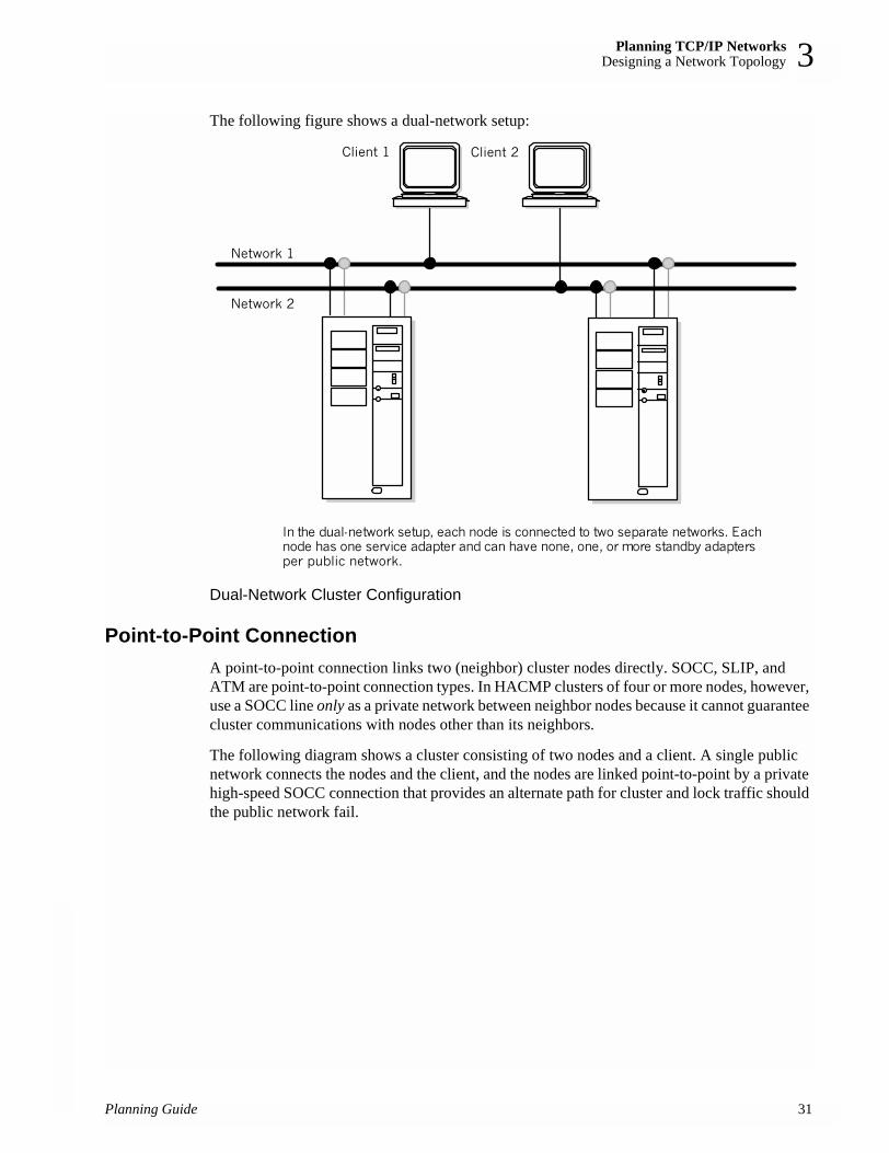
Dual NetworkA dual-network setup has two separate networks for communication. Nodes are connected to two networks, and each node has two service adapters available to clients. If one network fails, the remaining network can still function, connecting nodes and providing resource access to clients.
In some recovery situations, a node connected to two networks may route network packets from one network to another. In normal cluster activity, however, each network is separate—both logically and physically.
Keep in mind that a client, unless it is connected to more than one network, is susceptible to network failure.
In the single-network setup, each node is connected to one network.Each node has one service adapter and can have none, one, or morestandby adapters per public network.
Network
Client
Planning Guide
Planning TCP/IP NetworksDesigning a Network Topology 3
The following figure shows a dual-network setup:
Dual-Network Cluster Configuration
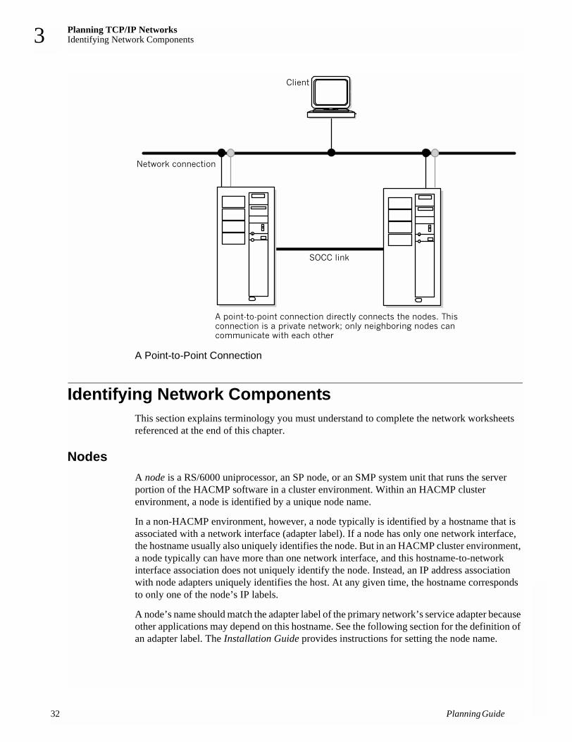
Point-to-Point Connection A point-to-point connection links two (neighbor) cluster nodes directly. SOCC, SLIP, and ATM are point-to-point connection types. In HACMP clusters of four or more nodes, however, use a SOCC line only as a private network between neighbor nodes because it cannot guarantee cluster communications with nodes other than its neighbors.
The following diagram shows a cluster consisting of two nodes and a client. A single public network connects the nodes and the client, and the nodes are linked point-to-point by a private high-speed SOCC connection that provides an alternate path for cluster and lock traffic should the public network fail.
Planning Guide 31
Planning TCP/IP NetworksIdentifying Network Components
32
3
A Point-to-Point Connection
Identifying Network ComponentsThis section explains terminology you must understand to complete the network worksheets referenced at the end of this chapter.
NodesA node is a RS/6000 uniprocessor, an SP node, or an SMP system unit that runs the server portion of the HACMP software in a cluster environment. Within an HACMP cluster environment, a node is identified by a unique node name.
In a non-HACMP environment, however, a node typically is identified by a hostname that is associated with a network interface (adapter label). If a node has only one network interface, the hostname usually also uniquely identifies the node. But in an HACMP cluster environment, a node typically can have more than one network interface, and this hostname-to-network interface association does not uniquely identify the node. Instead, an IP address association with node adapters uniquely identifies the host. At any given time, the hostname corresponds to only one of the node’s IP labels.
A node’s name should match the adapter label of the primary network’s service adapter because other applications may depend on this hostname. See the following section for the definition of an adapter label. The Installation Guide provides instructions for setting the node name.
Planning Guide

Planning TCP/IP NetworksIdentifying Network Components 3
Network AdaptersA network adapter (interface) connects a node to a network. A node typically is configured with at least two network interfaces for each network to which it connects: a service interface that handles cluster traffic, and one or more standby interfaces. A service adapter must also have a boot address defined for it if IP address takeover is enabled.
Adapters in an HACMP cluster have a label and a function (service, standby, or boot). The maximum number of network interfaces per node is 24.
You can assign a persistent IP label to a network on a node. Since a persistent IP label is an IP alias, it can be aliased on an adapter that already has a service or boot label defined on that node.
When configuring the SP with multiple networks and Enhanced Security, you should, to eliminate single points of failure, configure Kerberos service principals (godm, rcmd) on more than one, and preferably all, networks you plan to configure in your HACMP cluster environment. You can do this either at initial setup and installation of Kerberos on the SP, or later when you are customizing the nodes. See the Installation Guide for details about how to configure an HACMP cluster for Kerberos.
Adapter Label A network adapter is identified by an adapter label. For TCP/IP networks, the adapter label is the name in the /etc/hosts file associated with a specific IP address. Thus, a single node can have several adapter labels and IP addresses assigned to it. The adapter labels, however, should not be confused with the “hostname.”
The following example entries show that nodea has two Ethernet adapters, labeled svc and stdby. The adapter labels reflect separate network interface functions, each associated with a unique IP address:100.100.50.1 nodea-svc100.100.51.1 nodea-stdby
For boot adapters, you can simply add the suffix “boot” to the node name, as in nodea-boot. For more information on adapter functions, see the following section.
When deciding on an adapter label, keep in mind that the adapter label also can reflect an adapter interface name. For example, one interface can be labeled nodea-en0 and the other labeled nodea-en1, where en0 and en1 indicate the separate adapter names. Also, if you label your system hostname the same as your adapter label, do not use underscores since the use of underscores in hostnames may not be allowed with some levels of BIND.
Whichever naming convention you use for adapter labels in an HACMP cluster, be sure to be consistent.
Adapter Function In the HACMP environment, each adapter has a specific function that indicates the role it performs in the cluster. An adapter’s function can be service, standby, boot or persistent.
Planning Guide 33

Planning TCP/IP NetworksIdentifying Network Components
34
3
Service Adapter The service adapter is the primary connection between the node and the network. A node has one service adapter for each physical network to which it connects. The service adapter is used for general TCP/IP traffic and is the address the Cluster Information Program (Clinfo) makes known to application programs that want to monitor or use cluster services.
In configurations using rotating resources, the service adapter on the standby node remains on its boot address until it assumes the shared IP address. Consequently, Clinfo makes known the boot address for this adapter.
In an HACMP environment on the RS/6000 SP, the Ethernet adapters can be configured as service adapters but should not be configured for IP address takeover. For the SP switch network, service addresses used for IP address takeover are ifconfig alias addresses used on the css0 network. Note that the SP Switch2 MX2 Adapter is not supported in HACMP. It is supported only for the HACMP Enhanced Scalability (HACMP/ES) product feature.
In configurations using the Classical IP form of the ATM protocol (i.e. not ATM LAN Emulation), a maximum of seven service adapters per cluster is allowed if hardware address swapping is enabled.
Standby Adapter A standby adapter backs up a service adapter. If a service adapter fails, the Cluster Manager swaps the standby adapter’s address with the service adapter’s address. Using a standby adapter eliminates a network adapter as a single point of failure. A node can have no standby adapter, or it can have from one to seven standby adapters for each network to which it connects. Your software configuration and hardware constraints determine the actual number of standby adapters that a node can support.
Note: In an HACMP environment on the RS/6000 SP, for an IP address takeover configuration using the SP switch, standby adapters are not used.
Boot Adapter (Address) IP address takeover is an AIX facility that allows one node to acquire the network address of another node in the cluster. To enable IP address takeover, a boot adapter label (address) must be assigned to the service adapter on each cluster node. Nodes use the boot label after a system reboot and before the HACMP software is started.
Note: In an HACMP environment on the RS/6000 SP, boot addresses used in IP address takeover are ifconfig alias addresses used on the css0 network.
When the HACMP software is started on a node, the node’s service adapter is reconfigured to use the service label (address) instead of the boot label. If the node should fail, a takeover node acquires the failed node’s service address on its standby adapter, making the failure transparent to clients using that specific service address.
During the reintegration of the failed node, which comes up on its boot address, the takeover node will release the service address it acquired from the failed node. Afterwards, the reintegrating node will reconfigure its boot address to its reacquired service address.
Planning Guide

Planning TCP/IP NetworksIdentifying Network Components 3
Consider the following scenario: Suppose that Node A fails. Node B acquires Node A’s service address and services client requests directed to that address. Later, when Node A is restarted, it comes up on its boot address and attempts to reintegrate into the cluster on its service address by requesting that Node B release Node A’s service address. When Node B releases the requested address, Node A reclaims it and reintegrates into the cluster. Reintegration, however, fails if Node A has not been configured to boot using its boot address.
Note: The boot address does not use a separate physical adapter, but instead is a second name and IP address associated with a service adapter. It must be on the same subnetwork as the service adapter. All cluster nodes must have this entry in the local /etc/hosts file and, if applicable, in the nameserver configuration.
Persistent Adapter LabelStarting with HACMP 4.5, you can assign a persistent IP label to an HACMP network on a node. Since a persistent IP label is an IP alias, it can be set on an adapter that already has a service or boot label defined on that node.
Assigning a persistent IP label to a network on a node allows you to have a node-bound address on a cluster network that you can use for administrative purposes to access a specific node in the cluster.
A persistent IP label is an address which:• always stays on the same node (is node-bound)• co-exists on an adapter that already has a service or boot label defined• does not require installing an additional physical adapter on that node• is not part of any resource group.
When for administrative purposes you wish to reach a specific node in the cluster using the ping or telnet commands, theoretically you can contact either a standby, boot or service label on the node. But, due to a cluster event, boot and standby labels on the node could be replaced with a service address from another node; and the service label on the node may belong to a resource group that is currently down on that node.
Therefore, when you need to access a specific node in the cluster without worrying whether an IP service label you are using belongs to any of the resource groups present on that node, it is convenient to use a persistent IP label defined on that node.
Note: Since having multiple addresses assigned to one physical adapter reduces the potential network bandwidth of that adapter, you should use persistent node IP labels for administrative purposes only and for small amounts of network data transmission.
Once a persistent IP label is configured for a network interface on a particular network on a particular node, it becomes available on that node at boot time and remains configured on that network when HACMP is shut down on that node.
You can create persistent IP labels on the following types of IP-based networks that are supported by HACMP and HACMP/ES:• Ethernet
Planning Guide 35

Planning TCP/IP NetworksIdentifying Network Components
36
3
• Token Ring• FDDI• ATM LANE
You cannot configure a persistent IP label on the SP Switch and on the ATM Classical IP. You also cannot configure a persistent IP label on a serial cluster network.
A persistent IP label is put on the same adapter on a network on a node that has a boot or service label defined on it. A persistent IP label is not part of any resource group, and, in the case of an adapter failure, if there is a persistent label defined to the adapter, it can move only to boot or service adapter label on the same node on the same network, but does not move between the nodes in the cluster.
When HACMP detects that the adapter that has a boot or service address configured fails, and there is a persistent label defined on this adapter on this node, then the persistent label falls over to the same standby interface to which the boot/service address falls over on this node.
There is one exception to this rule. When a cascading resource group moves to a node (node B) other than its home node (node A), the service address takes over the standby interface on the node B. HACMP does not monitor the service address that took over the standby interface on the node B. Therefore, in this case, if a persistent label is configured on the service or boot adapter on the node B, and this adapter fails, a persistent address does not move to the standby interface which is hosting a service address of a cascading resource group not on its home node. In this case, a persistent address becomes unavailable on the node B.
If all adapters on the cluster network on a specified node fail, then a persistent IP label is unavailable on that node.If you are planning to monitor your HACMP cluster through a Tivoli console and do not plan to install a dedicated physical adapter for use with HATivoli on each node, you must assign persistent IP labels to adapters on each node in your cluster and configure HATivoli to use these labels in order to properly monitor IPAT through Tivoli. See the appendix on installing and configuring cluster monitoring with Tivoli in the Installation Guide for more information.If you were monitoring an earlier version of HACMP through Tivoli, you had to install some post-event scripts that created aliases for each node. See the chapter on upgrading in the Installation Guide for information on what happens to those prior aliases and post-event scripts when you migrate to version 4.5.
You create a persistent IP address label in SMIT the same way you create boot, service or standby address labels. See the Installation Guide for more information on how to assign persistent IP labels.
Network Interfaces The network interface is the network-specific software that controls the network adapter. The interface name is a three- or four-character string that uniquely identifies a network interface. The first two or three characters identify the network protocol. For example, en indicates a standard Ethernet network.
Planning Guide

Planning TCP/IP NetworksIdentifying Network Components 3
Network interfaces and their character identifiers are shown in the following table:
The next character is the number AIX assigns the device. For example, 0. An interface name of en0 indicates that this is the first standard Ethernet interface on the system unit.
NetworksNetworks in an HACMP cluster are identified by a name and an attribute.
Network Name The network name is a symbolic value that identifies a network in an HACMP environment. Cluster processes use this information to determine which adapters are connected to the same physical network. The network name is arbitrary, in most cases, but it must be used consistently. If several adapters share the same physical network, make sure that you use the same network name when defining these adapters.
Network Attribute A TCP/IP network’s attribute is either public or private.
Interface Identifier
Standard Ethernet en
Token-Ring tr
SLIP sl
FDDI fi
SOCC so
SP Switch css
ATM at
Public A public network connects from two to eight nodes and allows clients to monitor or access cluster nodes. Ethernet, Token-Ring, FDDI, and SLIP are considered public networks. Note that a SLIP line, however, does not provide client access.
Private A private network provides point-to-point communication between two nodes; it typically does not allow client access. A SOCC line or an ATM network also are private networks; however, an ATM network does allow client connections and may contain standby adapters. If an SP node is used as a client, the SP Switch network, although private, can allow client access. Note that the SP Switch2 MX2 Adapter is not supported in HACMP. It is supported only for the HACMP Enhanced Scalability (HACMP/ES) product feature.
Planning Guide 37

Planning TCP/IP NetworksDefining IP Addresses for Standby Adapters
38
3
Defining a Network Mask The HACMP software uses the subnet feature of TCP/IP to divide a single physical network into separate logical subnets. In order to use subnets, you must define a network mask for your system.
An IP address consists of 32 bits. Some of the bits form the network address; the remainder form the host address. The network mask (or netmask) determines which bits in the IP address refer to the network and which bits refer to the host, as shown in the following example:
A Network Mask in Decimal and Binary Format
In the preceding figure, the netmask is shown in both dotted decimal and binary format. A binary 1 indicates that a bit is part of the network address. A binary 0 indicates that a bit is part of the host address. In the preceding example, the network portion of the address occupies 24 bits; the host portion occupies eight bits. It is convenient (but not necessary) to define a subnet on an octet boundary.
See the AIX System Management Guide: Communications and Networks manual for more information about classes of addresses. AIX 5L manuals can be found online at http://publibn.boulder.ibm.com/cgi-bin/ds_rslt#1. Also, ask your network administrator about the class and subnets used at your site.
Defining IP Addresses for Standby Adapters The design of the HACMP software specifies that:• All client traffic be carried over the service adapter.• Standby adapters be hidden from client applications and carry only internal Cluster
Manager traffic.
To comply with these rules, pay careful attention to the IP addresses you assign to standby adapters. Standby adapters must be on a separate subnet from the service adapters, even though they are on the same physical network. Placing standby adapters on a different subnet from the service adapter allows HACMP to determine which adapter TCP/IP will use to send a packet to a network.
If there is more than one adapter on the same subnet with the same network address, there is no way to guarantee which of these adapters will be chosen by the IP as the transmission route. All choices will be correct, since each choice will deliver the packet to the correct network. To guarantee that only the service adapter handles critical traffic, you must limit the IP’s choice of
Planning Guide
Planning TCP/IP NetworksDefining IP Addresses for Standby Adapters 3
a transmission route to one adapter. This keeps all traffic off the standby adapter so that it is available for adapter swapping and IP address takeover (IPAT). Limiting the IP’s choice of a transmission route also facilitates identifying an adapter failure.
Note: The netmask for all adapters in an HACMP network must be the same even though the service and standby adapters are on different logical subnets. See the Concepts and Facilities Guide for more information about using the same netmask for all adapters.
Placing Standby Adapters on a Separate Subnet To place a standby adapter on a different subnet from a service adapter, give it an IP address that has a different network address portion.
Consider the following adapter IP address and network mask:IP address:100.100.50.121 01100100 01100100 00110010 01111001
Netmask:255.255.255.0 11111111 11111111 11111111 00000000
In this example, the network address is 100.100.50. The host address is 121. An adapter configured in this way can transmit packets destined to a network whose first three octets are 100.100.50.
Now consider a node with the following two network adapters:Adapter 1’s IP address:100.100.50.121 01100100 01100100 00110010 01111001Adapter 2’s IP address:100.100.50.25 01100100 01100100 00110010 00011001Netmask:255.255.255.0 11111111 11111111 11111111 00000000
In this example, suppose that a client program on this node wanted to send data to another client at address 100.100.50.112. You cannot predict whether adapter 1 or adapter 2 will transmit the datagram, because the destination IP address (100.100.50.112) can be reached through either adapter.
Now consider a node with the following configuration:Adapter 1’s IP address:100.100.50.121 01100100 01100100 00110010 01111001Adapter 2’s IP address:100.100.51.25 01100100 01100100 00110011 00011001Netmask:255.255.255.0 11111111 11111111 11111111 00000000
In this case, you can determine that the data destined for the client at address 100.100.50.112 will be sent through adapter 1, since it is the only candidate that can send the packet to the network with address 100.100.50.
Remember, pay careful attention to the IP addresses you assign to standby adapters as you complete the networks worksheet referenced at the end of this chapter.
Planning Guide 39

Planning TCP/IP NetworksDefining Boot Addresses
40
3
Although standby adapters are on the same physical network (and must be on the same netmask) as service adapters, standby adapters must be on a different logical subnet from the service adapters. Different HACMP networks may use different netmasks, but the netmask must be the same for all adapters within a given HACMP network.
Multiple Standby AdaptersIf you configure multiple standby adapters on cluster nodes, they all must be configured on the same subnet to handle cluster node failures. In addition, keep in mind that with multiple standby adapters configured, a swap_adapter event on the standby adapter routing heartbeats on a node may cause all standbys on the node to appear to fail, since only one heartbeat route exists per node for the standbys on that node.
Subnet Considerations for Cluster Monitoring with TivoliIn order to ensure the proper monitoring of IP address takeover in a Tivoli-monitored cluster, if you do not use dedicated physical adapters for Tivoli, you must create a persistent IP label (IP alias) for each node in the cluster on the same network and include this label in the /etc/hosts file and also in the Tivoli /etc/wlocalhost file. For information on configuring persistent IP labels in HACMP see the chapter on defining the cluster topology in the Installation Guide.
The subnet of the persistent node IP alias must meet these conditions:• The subnet of the persistent IP label must be different from the subnet of the node’s standby
adapters• The subnet of the persistent IP label may be the same as the subnet of the node’s boot and
service adapters• For proper monitoring of IPAT by Tivoli, the subnet of the persistent label must be the same
as the subnet of the non-cluster Tivoli Management Region node.
Note: If you already have Tivoli set up before you set up monitoring for the HACMP cluster, you may need to change the address of the Tivoli Management Region (TMR) node to match the persistent label.
For full instructions in configuring your cluster to be monitored by Tivoli, see the related appendix in the Installation Guide.
Defining Boot Addresses The design of the HACMP software specifies that:• All client traffic be carried over the service adapter.• Boot adapters be hidden from client applications and carry only internal Cluster Manager
traffic.
When using IP address takeover, you must define a boot address for each service adapter on which IP address takeover might occur.
The boot address and the service address must be on the same subnet. That is, the two addresses must have the same value for the network portion of the address; the host portion must be different.
Planning Guide

Planning TCP/IP NetworksDefining Boot Addresses 3
Use a standard formula for assigning boot addresses. For example, the boot address could be the host address plus 64. This formula yields the following boot addresses:NODE A service address: 100.100.50.135NODE A boot address: 100.100.50.199Network mask: 255.255.255.0
NODE B service address: 100.100.50.136NODE B boot address: 100.100.50.200Network mask: 255.255.255.0
Boot/Service/Standby Address Requirements for Resource GroupsThe following charts specify the boot, service, and standby address requirements for each resource group configuration in a two- and three-node cluster.
Planning Guide 41

Planning TCP/IP NetworksDefining Hardware Addresses
42
3
Boot, Service, and Standby Address Requirements for a Two-Node Cluster
Boot, Service, and Standby Address Requirements for a Three-Node Cluster
Defining Hardware AddressesThe hardware address swapping takeover facility works in tandem with IP address takeover. Hardware address swapping takeover maintains the binding between an IP address and a hardware address, which eliminates the need to flush the ARP cache of clients after an IP address takeover. This facility is supported for Ethernet, Token-Ring, FDDI, and ATM adapters.
Note: You cannot use hardware address swapping takeover on the SP Ethernet or SP Switch networks.
Resource Group Type Boot Adapters Service Adapters Standby Adapters
Cascading without IP address takeover (same for Cascading without Fallback)
none required One Two
Cascading with IP address takeover (same for Cascading Without Fallback)
One per highly available service address
One per highly available client connection
Two
Rotating Two One per node per network minus one
Two
Concurrent not applicable not applicable not applicable
Resource Group Type Boot Adapters Service Adapters Standby Adapters
Cascading without IP address takeover (same for Cascading without Fallback)
none required Three Three
Cascading with IP address takeover (same for Cascading Without Fallback)
One per highly available service address
One per highly available client connection
Three
Rotating Three One per node per network minus one
Three
Concurrent not applicable not applicable not applicable
Planning Guide

Planning TCP/IP NetworksDefining Hardware Addresses 3
Note that hardware address swapping takes about 60 seconds on a Token-Ring network, and up to 120 seconds on a FDDI network. These periods are longer than the usual time it takes for the Cluster Manager to detect a failure and take action.
Selecting an Alternate Hardware AddressThis section provides hardware addressing recommendations for Ethernet, Token Ring, FDDI, and ATM adapters. Note that any alternate hardware address you define for an adapter should be similar in form to the default hardware address the manufacturer assigned to the adapter.To determine an adapter’s default hardware address, use the netstat -i command (when the networks are active).
Using netstatTo retrieve hardware addresses using the netstat -i command, enter:netstat -i | grep link
which returns output similar to the following (leading 0s are suppressed):lo0 16896 link#1 186303 0 186309 0 0en0 1500 link#2 2.60.8c.2f.bb.93 2925 0 1047 0 0tr0 1492 link#3 10.0.5a.a8.b5.7b 104544 0 92158 0 0tr1 1492 link#4 10.0.5a.a8.8d.79 79517 0 39130 0 0fi0 4352 link#5 10.0.5a.b8.89.4f 40221 0 1 1 0fi1 4352 link#6 10.0.5a.b8.8b.f4 40338 0 6 1 0at0 9180 link#7 8.0.5a.99.83.57 54320 0 8 1 0at2 9180 link#8 8.0.46.22.26.12 54320 0 8 1 0
Specifying an Alternate Ethernet Hardware AddressTo specify an alternate hardware address for an Ethernet interface, begin by using the first five pairs of alphanumeric characters as they appear in the current hardware address. Then substitute a different value for the last pair of characters. Use characters that do not occur on any other adapter on the physical network.
For example, you could use 10 and 20 for node A and node B, respectively. If you have multiple adapters for hardware address swapping in each node, you can extend to 11 and 12 on node A, and 21 and 22 on node B.
Specifying an alternate hardware address for adapter interface en0 in the preceding output thus yields the following value:
To define this alternate hardware address to the cluster environment, see the Installation Guide.
Specifying an Alternate Token-Ring Hardware AddressTo specify an alternate hardware address for a Token-Ring interface, set the first two digits to 42, indicating that the address is set locally.
Original address 02608c2fbb93
New address 02608c2fbb10
Planning Guide 43

Planning TCP/IP NetworksDefining Hardware Addresses
44
3
Specifying an alternate hardware address for adapter interface tr0 in the preceding output thus yields the following value:
To define this alternate hardware address to the cluster environment, see the Installation Guide.
Specifying an Alternate FDDI Hardware Address (for Service Labels)To specify an alternate FDDI hardware address, enter the new address into the Adapter Hardware Address field as follows, without any decimal separators:
1. Use 4, 5, 6, or 7 as the first digit (the first nibble of the first byte) of the new address.
2. Use the last six octets of the manufacturer’s default address as the last six digits of the new address.
Here’s a list of some sample alternate addresses for adapter interface fi0 in the preceding output, shown with decimals for readability:40.00.00.b8.89.4f40.00.01.b8.89.4f50.00.00.b8.89.4f60.00.00.b8.89.4f7f.ff.ff.b8.89.4f
Specifying an Alternate ATM Hardware Address (for Service Labels)The following procedure applies to ATM Classic IP interface only. Hardware address swapping for ATM LAN Emulation adapters works just like hardware address swapping for the Ethernet and Token-Ring adapters that are being emulated.
An ATM adapter has a hardware address which is 20 bytes in length. The first 13 bytes are assigned by the ATM switch, the next six bytes are burned into the ATM adapter, and the last byte represents the interface number (known as the selector byte). The preceding example only shows the burned in six bytes of the address. To select an alternate hardware address, you replace the six burned in bytes, and keep the last selector byte. The alternate ATM adapter hardware address is a total of seven bytes.
To specify an alternate hardware address for an ATM Classic IP interface:
1. Use a value in the range of 40.00.00.00.00.00 to 7f.ff.ff.ff.ff.ff for the first six bytes.
2. Use the interface number as the last byte.
Since the interface number is hard-coded into the ATM hardware address, it must move from one ATM adapter to another during hardware address swapping. This imposes certain requirements and limitations on the HACMP configuration.
HACMP Configuration Requirements for ATM Hardware Address Takeover (Classical IP Only)
Multiple interfaces (Classic IP or LANE) can be configured over the same ATM device, and used as cluster adapters.
Original address 10005aa8b57b
New address 42005aa8b57b
Planning Guide

Planning TCP/IP NetworksDefining Hardware Addresses 3
High availability for the adapters that are configured over Classic IP or LANE is only guaranteed if any two cluster adapters belonging to the same network are configured over different ATM devices. Cluster verification will generate a warning for any pair of cluster adapters that belong to the same cluster network and are configured over the same ATM device.
If hardware address takeover (HWAT) is configured for cluster networks of type ATM, cluster verification checks for the following conditions so that conflicts between distinct ATM service IP labels with HWAT are avoided:• An ATM device can only take over one ATM service IP label that has HWAT configured.
If an ATM adapter on a node hosts cluster adapters of any two networks of type ATM, then this node cannot take over resource groups that have ATM service IP labels with HWAT on those networks.
• A node cannot own (take over) two resource groups that have ATM service IP labels with HWAT configured with the same number for the selector byte.
• If a resource group contains an ATM service IP label with HWAT, the selector byte number of that hardware address is exclusive. On any node that can possibly own the resource group, you cannot configure any adapters on Classic IP interfaces using the same selector byte number.
If a conflicting IP address is configured on an interface that is used outside HACMP, cluster verification will generate a warning.
Example of Hardware Address Takeover Configuration for ATMThe following two tables represent a cluster configuration at boot time. There are two ATM cluster networks denoted by the 1 or 2 in the adapter label. Therefore, adapters 1A, 1B, and 1C belong to NET1, while adapters 2A, 2B, and 2C belong to NET2. Resource groups RG1 and RG2 have ATM service IP labels with HWAT on each network.
The configuration information for each cluster node is as follows:
Node A Node B Node C
atm0 atm0 atm0
at0: boot1A at0: boot1B at0: boot1C
at1: stby2A at1: boot2C
atm1 atm1 atm1
at2: stby1A at1: stby1B at2: stby1C
at3: boot2A at3: stby2C
atm2
at2: boot2B
atm3
at3: stby2B
Planning Guide 45

Planning TCP/IP NetworksDefining Hardware Addresses
46
3
The resource group configuration is as follows:
The above configuration is valid for the following reasons (Note that the following are specific only to service IP labels with hardware address takeover defined):
1. Each ATM device (denoted by “atm#”) hosts at most one ATM service IP label with HWAT.• If both resource groups are online on the same node, their service IP labels are on
distinct ATM devices: svc1A will be on atm1, and svc2B on atm2.• The configuration would be invalid if Node C were included in RG_1 since atm1 on
Node C could potentially host both svc1A and svc2B.
2. The hardware address selector bytes (04 and 05) in the hardware addresses 42.a.a.a.a.a.04 and 42.b.b.b.b.b.05 do not occur as Classic IP interface numbers on any node.
3. The selector bytes are unique. This is required since the resource groups have a node in common.
Hardware Address Takeover in Classic IP May Cause Temporary Unavailability of Other Network InterfacesIf a Classic IP interface configured as a cluster adapter participates in an IP address takeover or adapter swap with HWAT, the hardware address of the underlying ATM device will be changed. Clients such as LANE devices or Classic IP interfaces that are configured over that device will be brought temporarily into the defined or detached state, and hence be temporarily unavailable.
In particular, an IP address takeover or adapter swap with HWAT for service IP labels of type ATM may cause temporary unavailability of other service IP labels that are configured over the ATM devices involved.
Network Configuration Requirements for ATM Hardware Address Takeover (Classical IP and LAN Emulation)
Hardware address swapping for ATM requires that all adapters that can be taken over for a given service address be attached to the same ATM switch.
Avoiding Network ConflictsNote the following information to configure the networks in order to avoid network conflicts.
Hardware AddressEach network adapter is assigned a unique hardware address when it is manufactured, which ensures that no two adapters have the same network address. When defining a hardware address for a network adapter, ensure that the defined address does not conflict with the hardware address of another network adapter in the network. Two network adapters with a common hardware address can cause unpredictable behavior within the network.
Resource Group Nodes Service IP Label Hardware Address
RG_1 A, B svc1A 42.a.a.a.a.a.04
RG_2 B, C svc2B 42.b.b.b.b.b.05
Planning Guide

Planning TCP/IP NetworksUsing HACMP with NIS and DNS 3
IP AddressCluster Verification will notify you if you have a duplicate IP address. After correcting the duplicate address, resynchronize cluster topology.
Using HACMP with NIS and DNSHACMP facilitates communication between the nodes of a cluster so that each node can determine whether the designated services and resources are available. Resources can include, but are not limited to, IP addresses and names and storage disks.
Subnetting the service and standby adapters (using TCP/IP) and having at least two separate networks (Ethernet and RS232) permits HACMP to determine whether a communication problem exists in the adapter, the network, or another common component such as TCP/IP software itself. The ability to subnet the adapters ensures that HACMP can direct the keepalive traffic from service to standby adapters, standby to service adapters, standby to standby adapters, and so on. For example, if there are two nodes in a cluster, and both standby and service adapters of Node A can receive and send to the standby adapter of node B, but cannot communicate with the service adapter of Node B, then it can be assumed that the service adapter is not working properly. HACMP recognizes this and performs the swap between the service and standby adapters.
Some of the commands used to perform the swap require IP lookup. This defaults to a nameserver for resolution if NIS or DNS is operational. If the nameserver was accessed via the adapter that is down, the request will time-out. To ensure that the cluster event (in this case an adapter swap) completes successfully and quickly, HACMP disables NIS or DNS hostname resolution during the IP address swapping by setting the AIX environment variable NSORDER= local. It is therefore required that the nodes participating in the cluster have entries in the /etc/hosts file.
How HACMP Enables and Disables NameservingThis section provides some additional details on the logic a system uses to perform hostname resolution and how HACMP enables and disables DNS and NIS.
Note: If you are using NIS, it is recommended to have the NIS master server outside the cluster, and have the cluster nodes run as NIS slave servers. At a minimum, every HACMP node must be able to access NIS master or slave servers on a local subnet, and not via a router.
If a node is using either domain nameserving or NIS, the hostname is normally resolved by contacting a suitable server. At best, this causes a time delay; at worst, no response is ever returned because communication with the server is lost. For example, if NIS alone is running, hostname resolution is performed via the following logic in AIX:
Planning Guide 47

Planning TCP/IP NetworksUsing HACMP with NIS and DNS
48
3
Hostname Resolution when NIS Alone is Running
Note: The following applies if the NIS configuration maps include the host map.
As shown, if the NIS host tables were built with the -b flag, the NIS Server continues its search via domain nameserving if that option is available. The key point, however, is that under certain circumstances (for example, an adapter being down, and the NIS server being unavailable), hostname resolution should be localized for quick response time. This infers that the local /etc/hosts file should be consulted, and the systems that may be involved in a cluster reconfiguration must be placed within the file in addition to loopback and the local hostname. It also means that the client portion of NIS that is running on that machine must be turned off. This is the case if the cluster node is an NIS client regardless of its status as a server (master or slave). Remember, even an NIS server uses the ypbind to contact the ypserv daemon running either on the master server or a slave server to perform the lookup within the current set of NIS maps.
Similarly, the logic followed by DNS (AIX) is:
Is NIS running? Resolved
Failedno
no
see /etc/hosts
yes found
yes
check DNS
notfound
failed
no Resolved
Planning Guide

Planning TCP/IP NetworksPlanning for Cluster Performance 3
Hostname Resolution with DNS
In this situation, if both DNS and NIS were not disabled, a response to a hostname request might be as long as the time required for both NIS and DNS to time-out. This would hinder HACMP’s system reconfiguration, and increase the takeover time required to maintain the availability of designated resources (IP address). Disabling these services is the only reliable and immediate method of expediting the communication changes HACMP is attempting to accomplish.
HACMP 4.5 disables NIS and DNS during the process of IP address swapping by temporarily setting the AIX environment variable NSORDER=local within the event scripts. This is done to ensure that the external name service does not cause AIX to map the service IP address to the wrong adapter.
Planning for Cluster PerformanceHACMP 4.5 provides easier and greater control over several tuning parameters that affect the cluster’s performance. Setting these tuning parameters correctly to ensure throughput and adjusting the HACMP failure detection rate can help avoid “failures” caused by heavy network traffic.
Planning Guide 49

Planning TCP/IP NetworksPlanning for Cluster Performance
50
3
Cluster nodes sometimes experience extreme performance problems, such as large I/O transfers, excessive error logging, or lack of memory. When this happens, the Cluster Manager can be starved for CPU time. It might not reset the “deadman switch” within the time allotted. Misbehaved applications running at a priority higher than the cluster manager can also cause this problem.
The “deadman switch” is the AIX kernel extension that halts a node when it enters a hung state that extends beyond a certain time limit. This enables another node in the cluster to acquire the hung node’s resources in an orderly fashion, avoiding possible contention problems. If the deadman switch is not reset in time, it can cause a system panic and dump under certain cluster conditions.
It is highly recommended to set the two following AIX tuning parameters correctly to avoid some of the HACMP performance problems noted here:• AIX high and low watermarks for I/O pacing• AIX sync frequency rate.
Setting these AIX tuning parameters correctly may prevent having to change the HACMP Network Module Failure Detection Rate. You can also set the following HACMP network tuning parameters for each type of network:• Failure Detection Rate
• Heartbeat Rate• Failure Cycle
• Network Grace Period.
Setting I/O PacingAIX users have occasionally seen poor interactive performance from some applications when another application on the system is doing heavy input/output. Under certain conditions I/O can take several seconds to complete. While the heavy I/O is occurring, an interactive process can be severely affected if its I/O is blocked or if it needs resources held by a blocked process.
Under these conditions, the HACMP software may be unable to send keepalive packets from the affected node. The Cluster Managers on other cluster nodes interpret the lack of keepalives as node failure, and the I/O-bound node is “failed” by the other nodes. When the I/O finishes, the node resumes sending keepalives. Its packets, however, are now out of sync with the other nodes, which then kill the I/O-bound node with a RESET packet.
You can use I/O pacing to tune the system so that system resources are distributed more equitably during high disk I/O. You do this by setting high- and low-water marks. If a process tries to write to a file at the high-water mark, it must wait until enough I/O operations have finished to make the low-water mark.
By default, AIX is installed with high- and low-water marks set to zero, which disables I/O pacing.
While enabling I/O pacing may have a slight performance effect on very I/O intensive processes, it is required for an HACMP cluster to behave correctly during large disk writes. If you anticipate heavy I/O on your HACMP cluster, you should enable I/O pacing.
Planning Guide

Planning TCP/IP NetworksPlanning for Cluster Performance 3
Although the most efficient high- and low-water marks vary from system to system, an initial high-water mark of 33 and a low-water mark of 24 provides a good starting point. These settings only slightly reduce write times and consistently generate correct fallover behavior from the HACMP software.
See the AIX Performance Monitoring & Tuning Guide for more information on I/O pacing.
Setting Syncd FrequencyThe syncd setting determines the frequency with which the I/O disk-write buffers are flushed. Frequent flushing of these buffers reduces the chance of deadman switch time-outs.
The AIX default value for syncd as set in /sbin/rc.boot is 60. It is recommended to change this value to 10. Note that the I/O pacing parameter setting should be changed first. You should not need to adjust this parameter again unless you get frequent time-outs.
Setting Failure Detection ParametersEach supported cluster network in a configured HACMP cluster has a corresponding cluster network module. Each network module monitors all I/O to its cluster network.
Each network module maintains a connection to other network modules in the cluster. The Cluster Managers on cluster nodes send messages to each other through these connections. Each network module is responsible for maintaining a working set of service adapters and for verifying connectivity to cluster peers. The network module also is responsible for reporting when a given link actually fails. It does this by sending and receiving periodic heartbeat messages to or from other network modules in the cluster.
Currently, network modules support communication over the following types of networks:• Serial (RS232)• Target-mode SCSI• Target-mode SSA• Ethernet• Token Ring• FDDI• SOCC• SLIP• SP Switch• Fiber Channel Switch (FCS)• ATM.
The Failure Detection Rate is made up of two components: • failure cycle (cycle): the number of heartbeats that must be missed before detecting a
failure.• heartbeat rate (hbrate): the number of microseconds between heartbeats.
Together, these two values determine the Failure Detection Rate. For example, for a NIM with a heartbeat rate of 1,000,000 microseconds and a cycle value of 12, the Failure Detection Rate would be 12 (one second x 12 cycles).
Planning Guide 51

Planning TCP/IP NetworksPlanning for Cluster Performance
52
3
The default heartbeat rate is usually optimal. Speeding up or slowing down failure detection is a small, but potentially significant area where you can adjust cluster fallover behavior. However, the amount and type of customization you add to event processing has a much greater impact on the total fallover time. You should test the system for some time before deciding to change the failure detection speed of any network module.
If HACMP cannot get enough CPU resources to send heartbeats on IP and serial networks, other nodes in the cluster will assume the node has failed, and initiate takeover of the node’s resources. In order to ensure a clean takeover, the Deadman Switch crashes the busy node if it is not reset within a given time period. The Deadman Switch uses the following formula:N=((keepalives * missed_keepalives) -1)orN=(network failure detection rate) -1Where keepalives (heartbeat rate) and missed_keepalives (failure cycle) are for the slowest network in the cluster.
The following table shows the Deadman Switch timeouts for IP and non-IP networks. Each of these times is one second less than the time to trigger an HACMP event on that network. Remember that the Deadman Switch is triggered on the slowest network in your cluster.
Deadman Switch Timeouts (in Seconds) for Different Heartbeat Settings
If you decide to change the failure detection rate of a network module, keep the following considerations in mind:• Failure detection is dependent on the fastest network linking two nodes. • The failure detection rate of networks varies, depending on their characteristics. See the
Installation Guide for default values of failure detection rates for IP and non-IP networks.• Before altering the NIM, you should give careful thought to how much time you want to
elapse before a real node failure is detected by the other nodes and the subsequent takeover is initiated.
• Faster heartbeat rates may lead to false failure detections, particularly on busy networks. For example, bursts of high network traffic may delay heartbeats and this may result in nodes being falsely ejected from the cluster. Faster heartbeat rates also place a greater load on networks. If your networks are very busy and you experience false failure detections, you can try slowing the failure detection speed on the network modules to avoid this problem.
• It is recommended that you first set the Failure Detection Rate to predefined values (Normal, Slow or Fast) before trying to customize this rate. If you do need to customize, then change the hbrate and adjust the cycle value as needed to reach the desired Failure Detection Rate.
• The Failure Detection Rate should be set equally for every network module used by the cluster. The change must be synchronized across cluster nodes. The new values will become active the next time cluster services are started.
Network Type DMS Timeout for SLOW hb rate
DMS Timeout for NORMAL hb rate
DMS Timeout for FAST hb rate
IP Network 47 19 9
Non-IP Network 47 19 9
Planning Guide

Planning TCP/IP NetworksAdding the TCP/IP Network Topology to the Cluster Diagram 3
• Whenever a change is made to any of the values that affect the failure detection time - failure cycle (FC), heartbeat rate (HB) or failure detection rate - the new value of these parameters is sent as an output to the screen in the following message: SUCCESS: Adapter Failure Detection time is now FC * HB* 1 or SS seconds
Network Grace Period is the time period in which, after a network failure was detected, further network failures of the same type would be ignored. Network Grace Period is network specific and may also be set in SMIT. The default values for all network types are 60 seconds, except for Token Ring and ATM. Grace period value for Token Ring and ATM is 90 seconds.
See the Installation Guide for more details on configuring and adjusting these parameters.
Adding the TCP/IP Network Topology to the Cluster Diagram
You can now add the TCP/IP network topology to the cluster diagram. The following cluster diagram includes the TCP/IP network topology:
A Cluster Diagram with TCP/IP Network Topology
To add the network topology information to your diagram:
1. Sketch in the networks, including any point-to-point connections between nodes.
2. Name each network and indicate its attribute. Remember, a network name is an arbitrary string. For example, in the preceding figure, the public Ethernet network is named ether1 and the private SOCC point-to-point connection is named socc1.
Planning Guide 53

Planning TCP/IP NetworksCompleting the TCP/IP Networks Worksheets
54
3
3. Add the network adapters. Give each adapter a name and indicate its function. If you are using IP address takeover or rotating resources, remember to include a boot address for each service adapter that can be taken over. For example, in the preceding figure, the service adapter for the Ethernet network on the node nodeA is named NodeA-svc, and the corresponding boot adapter is NodeA-boot.
Note that the names and IDs that you define (for example, ether1) apply only within the specific HACMP cluster and have no meaning outside of it.
Completing the TCP/IP Networks WorksheetsBecause the HACMP software supports multiple TCP/IP networks within a single cluster, installing a network topology to support HACMP can be a complex task. Use the following worksheets in Appendix A: Planning Worksheets, to make the process easier:• TCP/IP Networks Worksheet (one for the cluster)• TCP/IP Networks Adapter Worksheet (one for each node)
Appendix A includes examples of completed worksheets.
Note that the worksheet instructions here correspond to the paper worksheets and do not exactly match the online worksheets. In the online worksheet program, you would enter network configuration information in the “Networks” and “Adapters” panels.
Completing the TCP/IP Networks Worksheet The TCP/IP Networks Worksheet helps you organize the networks for an HACMP cluster. To complete the worksheet:
1. Enter the cluster ID in the Cluster ID field.
2. Enter the cluster name in the Cluster Name field.
3. In the Network Name field, give each network a symbolic name. You use this value during the install process when you configure the cluster. Remember that each SLIP and SOCC line is a distinct network and must be listed separately.
4. Indicate the network’s type in the Network Type field. For example, it may be Ethernet, Token-Ring, and so on.
5. Indicate the network’s function in the Network Attribute field. That is, the network can be public or private.
6. In the Netmask field, provide the network mask of each network. The network mask is site dependent and must be the same for all adapters in the HACMP network.
7. In the Node Names field, list the names of the nodes connected to each network. Refer to your cluster diagram.
Completing the TCP/IP Network Adapter WorksheetThe TCP/IP Network Adapter Worksheet helps you define the network adapters connected to each cluster node. Complete the following steps for each node on a separate worksheet:
1. Enter the node name in the Node Name field.
Planning Guide

Planning TCP/IP NetworksWhere You Go From Here 3
2. Leave the Interface Name field blank. You will enter values in this field after you configure the adapter following the instructions in the Installation Guide.
3. Enter the symbolic name of the adapter in the Adapter IP Label field.
4. Identify the adapter’s function as service, standby, or boot in the Adapter Function field.
5. Enter the IP address for each adapter in the Adapter IP Address field. Note that the SMIT Add an Adapter screen displays an Adapter Identifier field that correlates to this field on the worksheet.
6. Enter the name of the network to which this network adapter is connected in the Network Name field. Refer to the TCP/IP Networks Worksheet for this information.
7. Identify the network as public or private in the Network Attribute field. Refer to the TCP/IP Networks Worksheet for this information.
8. This field is optional. If you are using IP address takeover or rotating resources, in the Boot Address field enter the boot address for each service address that can be taken over.
9. This field is optional. If you are using hardware address swapping, in the Adapter HW Address field enter the hardware address for each service address with an assigned boot address. The hardware address is a 12 or 14 digit hexadecimal value. Usually, hexadecimal numbers are prefaced with “0x” (zero x) for readability. Do not use colons to separate the numbers in the adapter hardware address.
Note: Entries in the Adapter HW Address field should refer to the locally administered address (LAA), which applies only to the service adapter.
For each cluster node, repeat these steps on a separate TCP/IP Network Adapter Worksheet.
Where You Go From HereYou have now planned the TCP/IP network topology for the cluster. The next step in the planning process is to lay out the serial network topology for the cluster. Chapter 4: Planning Serial Networks, describes this process.
Planning Guide 55

Planning TCP/IP NetworksWhere You Go From Here
56
3
Planning Guide
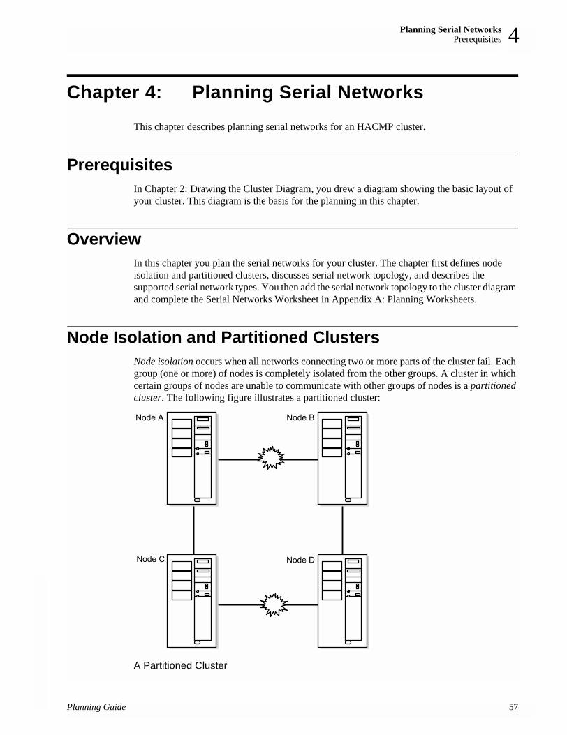
Planning Serial NetworksPrerequisites 4
Chapter 4: Planning Serial NetworksThis chapter describes planning serial networks for an HACMP cluster.
PrerequisitesIn Chapter 2: Drawing the Cluster Diagram, you drew a diagram showing the basic layout of your cluster. This diagram is the basis for the planning in this chapter.
OverviewIn this chapter you plan the serial networks for your cluster. The chapter first defines node isolation and partitioned clusters, discusses serial network topology, and describes the supported serial network types. You then add the serial network topology to the cluster diagram and complete the Serial Networks Worksheet in Appendix A: Planning Worksheets.
Node Isolation and Partitioned ClustersNode isolation occurs when all networks connecting two or more parts of the cluster fail. Each group (one or more) of nodes is completely isolated from the other groups. A cluster in which certain groups of nodes are unable to communicate with other groups of nodes is a partitioned cluster. The following figure illustrates a partitioned cluster:
A Partitioned Cluster
Node A Node B
Node C Node D
Planning Guide 57

Planning Serial NetworksSerial Network Topology
58
4
The problem with a partitioned cluster is that each node on one side of the partition interprets the absence of heartbeats from the nodes on the other side to mean that those nodes have failed, and generates node failure events for those nodes. Once this occurs, nodes on each side of the cluster (if so configured) attempt to take over resources from nodes that are still active and, therefore, still legitimately own those resources. These attempted takeovers can cause unpredictable results in the cluster—for example, data corruption due to a disk being reset.
To guard against the failure of the TCP/IP subsystem and to prevent partitioned clusters, it is strongly recommended that each node in the cluster be connected to its neighboring node by a point-to-point serial network, thus forming a logical “ring.” This logical ring of serial networks reduces the chance of node isolation by allowing neighboring Cluster Managers to communicate even when all TCP/IP-based networks fail.
Serial networks are especially important in concurrent access configurations so that data does not become corrupted when TCP/IP traffic among nodes is lost.
It is important to understand that the serial network does not carry TCP/IP communication between nodes; it only allows nodes to exchange heartbeats and control messages so that Cluster Managers have accurate information about the status of peer nodes.
Serial Network TopologyAs mentioned in the preceding section, a serial network reduces the occurrence of node isolation (and thus spurious resource takeovers) by allowing Cluster Managers to communicate even after all TCP/IP-based networks have failed. To eliminate the TCP/IP subsystem as a single point of failure within a cluster, the serial networks must be set up so that all Cluster Managers can learn the status of other Cluster Managers in the cluster.
Each node in the cluster must have a point-to-point serial network connection with all other nodes in the cluster. The following list indicates the number of serial network connections needed to eliminate the TCP/IP subsystem as a single point of failure for a four-node cluster with Nodes A, B, C, and D:• Node A to Nodes B, C, and D• Node B to Nodes A, C, and D• Node C to Nodes A, B, and D• Node D to Nodes A, B, and C
Note that in order to form the correct configuration, each node must be connected to all other nodes.
Supported Serial Network TypesThe HACMP software supports the following serial networks: a RS232 serial line, a SCSI-2 Differential or SCSI-2 Differential Fast/Wide bus using target mode SCSI, and target mode SSA.
RS232 Serial LineIf you are using shared disk devices other than SSA or SCSI-2 Differential or SCSI-2 Differential Fast/Wide devices, you must use RS232 serial adapters between nodes.
Planning Guide

Planning Serial NetworksSerial Network Topology 4
The RS232 serial line is classified as a tty device requiring a dedicated serial port at each end.You can label the tty device using any name or characters you choose. For example, if a node called nodeA is using a tty device as its serial line, you can label its adapter arbitrarily as nodeA-serial, or you can label it nodeA-tty1 to reflect the AIX-assigned device number.
See the Installation Guide for information on how to configure the RS232 serial line as a serial network in an HACMP cluster.
Note: On the SP thin or wide nodes there are no serial ports available. Therefore, any HACMP configurations that require a tty network need to make use of a serial adapter.
Note: Certain RS/6000 systems do not support the use of native serial ports in an HACMP RS232 serial network. Configuration of an RS232 serial network on some systems requires a PCI multi-port Async card.
Target Mode SCSIYou can configure a SCSI-2 bus as an HACMP serial network only if you are using SCSI-2 Differential or SCSI-2 Differential Fast/Wide devices. SCSI-1 Single-Ended and SCSI-2 Single-Ended do not support serial networks in an HACMP cluster. The advantage of using the SCSI-2 Differential bus is that it does not require a dedicated serial port at each end of the connection. It is recommended that you use a maximum of four target mode SCSI networks in a cluster.
The target mode SCSI device that connects nodes in an HACMP cluster is identified by a seven-character name string, where the characters tmscsi are the first six characters and the seventh character is the number AIX assigns to the device (for example, tmscsi1).
See the Installation Guide for information on configuring a SCSI-2 Differential or SCSI-2 Differential Fast/Wide bus as a serial network in an HACMP cluster.
Target Mode SSAYou can configure a target mode SSA connection between nodes sharing disks connected to SSA on Multi-Initiator RAID adapters (FC 6215 and FC 6219). The adapters must be at Microcode Level 1801 or later.
You can define a serial network to HACMP that connects all nodes on an SSA loop. By default, node numbers on all systems are zero. In order to configure the target mode devices, you must first assign a unique node number to all systems on the SSA loop. Do not use the number 0.
The target mode SSA device that connects nodes in an HACMP cluster is identified by a six-character name string, where the characters tmssa are the first five characters and the sixth character is the unique node number you assign to the device (for example, tmssa1).
Configuring the target mode connection creates two special files in the /dev directory of each node, the /dev/tmssa#.im and /dev/tmssa#.tm files. The file with the .im extension is the initiator, which transmits data. The file with the .tm extension is the target, which receives data.
Planning Guide 59

Planning Serial NetworksPlanning HACMP Serial Networks over Longer Distances
60
4
Planning HACMP Serial Networks over Longer DistancesHACMP serial networks may be extended over longer distances through the use of extender technologies. Target Mode SCSI and Target Mode SSA networks can use SCSI Bus Extenders or SSA Optical Extenders to achieve longer distances. RS232 links may be extended over longer distances through the use of other hardware devices such as:• Optical line drivers• Short-haul modems• PTT-supplied RS232 lines.
When planning longer-distance serial networks, take care to choose the correct devices and ensure that the infrastructure that connects these devices such as fibre or copper cabling is within the operational tolerances for the devices at the distances required. When extending RS232 links, selection of these devices should ensure that the device must support the full RS232 protocol (all pins) and that the device must be capable of supporting the distance required at a minimum line speed of 9600 bps.
Adding the Serial Network Topology to the Cluster Diagram
You now add the serial network topology to the cluster diagram as shown in the following figure:
A Cluster Diagram with Serial Network Topology
Planning Guide

Planning Serial NetworksCompleting Serial Networks and Serial Network Adapter Worksheets 4
To add the serial network topology to the cluster diagram:
1. Sketch in the serial networks. Remember, it is recommended that a serial network connect each pair of adjoining nodes.
2. Name each network; then indicate that its attribute is serial. A network name is an arbitrary string. For example, you could name an RS232 line serial1.The cluster in the preceding figure has a single serial network named rs2321.
3. Add the serial network adapters (if planning for a tmscsi connection) or specify a tty port connection, then give each a name. Indicate its function as service. For example, the node Node1 is using tty as its serial line connection; its adapter label is Node1-tty. If you plan for a tmscsi connection, its adapter label might be Node1-tmscsi2.
At this point, you should have a cluster diagram similar to the one in the preceding figure.
Completing Serial Networks and Serial Network Adapter Worksheets
After completing a cluster diagram, use the following paper worksheets, provided in Appendix A: Planning Worksheets, to record the serial network topology for your cluster:• Serial Networks Worksheet (one for the cluster)• Serial Network Adapter Worksheet (one for each node).
Appendix A: Planning Worksheets includes examples of completed worksheets.
See Appendix B: Using the Online Planning Worksheet Program if you are using the online planning worksheets.
Completing the Serial Networks WorksheetThe Serial Networks Worksheet helps you organize the serial networks for an HACMP cluster. To complete the Serial Networks Worksheet:
1. Enter the cluster ID in the Cluster ID field.
2. Enter the cluster name in the Cluster Name field.
3. Give each network a symbolic name in the Network Name field. Remember, each RS232 serial line, target mode SSA loop, or target mode SCSI-2 Differential bus is a distinct network and must be listed separately.
4. In the Network Type field, indicate the network’s type as an RS232 serial line, target mode SSA loop, or a target mode SCSI-2 Differential bus.
5. Indicate the network’s attribute as serial in the Network Attribute field.
6. List the names of the nodes connected to each serial network in the Node Names field. Refer to your cluster diagram.
7. Use the Miscellaneous Data field to record any extra information about devices used to extend serial links, for instance modem number or extender information.
Planning Guide 61

Planning Serial NetworksWhere You Go From Here
62
4
Note: None of these serial networks use the TCP/IP protocol; therefore they do not require a netmask.
Completing the Serial Network Adapter WorksheetThe Serial Network Adapter Worksheet helps you define the serial connections between cluster nodes. Complete the following steps for each node on a separate worksheet:
1. Enter the node name in the Node Name field.
2. Enter the slot number used to make the serial connection.
3. Leave the Interface Name field blank. You will enter the device name in this field after you configure the serial adapters during installation.
4. Enter the symbolic name of the adapter in the Adapter Label field.
5. Enter the name of the network to which this adapter is connected in the Network Name field. Refer to the Serial Networks Worksheet for the network name.
6. Identify the network as serial in the Network Attribute field.
7. Identify the adapter’s function as service in the Adapter Function field.
Repeat these steps on a new Serial Network Adapter Worksheet for each node in the cluster.
Where You Go From HereYou have now planned the serial networks for the cluster. The next step in the planning process is to lay out the shared disk configuration for your cluster, described in the following chapter.
Planning Guide

Planning Shared Disk and Tape DevicesPrerequisites 5
Chapter 5: Planning Shared Disk and Tape Devices
This chapter discusses information you must consider before configuring shared external disks in an HACMP cluster. It also includes information about planning to use SCSI or Fibre Channel tape drives as cluster resources.
PrerequisitesRead the Concepts and Facilities Guide for a discussion of the shared disk access methods supported by the HACMP software.
Also, refer to AIX documentation for the general hardware and software setup for your disks and tape devices.
OverviewThe HACMP software supports several shared disk configurations. Choosing the best setup for your needs requires careful thought before actually installing the disks. This chapter specifically includes information to help you:• Choose a disk technology.• Plan shared and non-shared storage.• Plan to install any of the following SCSI disk configurations: SCSI-2 SE, SCSI-2
Differential, SCSI-2 Differential Fast/Wide, IBM 7137 Disk Array, IBM 7135 models 110 and 210 RAIDiant Disk Arrays, IBM 2105 Versatile Storage Server models B09 and 100 or Enterprise Storage Server Models. Adapter requirements for each configuration are included in the planning considerations. The arrays can appear to the host as multiple SCSI devices. Use the general SCSI disk instructions in this chapter to plan for these arrays.
• Plan to use an IBM Serial Storage Architecture (SSA) disk subsystem in your configuration, such as the IBM 7133 disk subsystem. Adapter requirements are included in the planning considerations.
• Plan to use a SCSI streaming tape drive or a Direct Fibre Channel Tape unit attachment as a cluster resource.
After reading this chapter, you will be able to complete the shared disk configuration portion of your cluster diagram. Completing this diagram will make installing disks and arrays easier.
Choosing a Shared Disk TechnologyThe HACMP software supports the following disk technologies as shared external disks in a highly available cluster: • SCSI-2 SE, SCSI-2 Differential, and SCSI-2 Differential Fast/Wide adapters and drives• IBM SSA adapters and SSA disk subsystems.
Planning Guide 63

Planning Shared Disk and Tape DevicesChoosing a Shared Disk Technology
64
5
You can combine these technologies within a cluster. Before choosing a disk technology, however, review the considerations for configuring each technology as described in this section.
Note: See the appendix on OEM disks in the Administration Guide for information on installing and configuring OEM disks.
SCSI Disks The HACMP software supports the following SCSI disk devices and arrays as shared external disk storage in cluster configurations:• SCSI-2 SE, SCSI-2 Differential, and SCSI-2 Differential Fast/Wide disk devices• The IBM 7135-110 and 7135-210 RAIDiant Disk Arrays• The IBM 7137 Disk Array• The IBM 2105-B09 and 2105-100 Versatile Storage Servers• The IBM 2105-E-10 and 2105-E-20 Enterprise Storage Servers
These devices and arrays are described in the following section.
SCSI-2 SE, SCSI-2 Differential, and SCSI-2 Differential Fast/Wide Disk DevicesThe benefit of the SCSI implementation is its low cost. It provides a shared disk solution that works with most supported RISC System/6000 processor models (including the SP and the SMP) and requires minimal hardware overhead.
In an HACMP cluster, shared SCSI disks are connected to the same SCSI bus for the nodes that share the devices. They may be used in both concurrent and non-concurrent modes of access. In a non-concurrent access environment, the disks are “owned” by only one node at a time. If the owner node fails, the cluster node with the next highest priority in the resource chain acquires ownership of the shared disks as part of fallover processing. This ensures that the data stored on the disks remains accessible to client applications. The following restrictions, however, apply to using shared SCSI disks in a cluster configuration:• SCSI-2 SE, SCSI-2 Differential and SCSI-2 Differential Fast/Wide disks and disk arrays
support non-concurrent shared disk access. The only SCSI-2 Differential disk devices that support concurrent shared disk access are the IBM 7135-110 and 7135-210 RAIDiant Disk Arrays, the IBM 7137 Disk Array, and the IBM 2105-B09 and 2105-100 Versatile Storage Servers.
• Different types of SCSI buses can be configured in an HACMP cluster. Specifically, SCSI-2 Differential and SCSI-2 Differential Fast/Wide devices can be configured in clusters of up to four nodes, where all nodes are connected to the same SCSI bus attaching the separate device types. (You cannot mix SCSI-2 SE, SCSI-2 Differential and SCSI-2 Differential Fast/Wide devices on the same bus.)
• You can connect the IBM 7135-210 RAIDiant Disk Array only to High Performance SCSI-2 Differential Fast/Wide adapters, while the 7135-110 RAIDiant Disk Array cannot use those High Performance Fast/Wide adapters.
Planning Guide

Planning Shared Disk and Tape DevicesChoosing a Shared Disk Technology 5
• You can connect up to sixteen devices to a SCSI-2 Differential Fast/Wide bus. Each SCSI adapter and disk is considered a separate device with its own SCSI ID. The SCSI-2 Differential Fast/Wide maximum bus length of 25 meters provides enough length for most cluster configurations to accommodate the full sixteen-device connections allowed by the SCSI standard.
• Do not connect other SCSI devices, such as CD ROMs or tape drives, to a shared SCSI bus.• You cannot assign SCSI IDs 0, 1, or 2 to the IBM High Performance SCSI-2 Differential
Fast/Wide Adapter; the adapter restricts the use of these IDs. Likewise, you cannot assign SCSI IDs 0, 1, or 8 through 15 to the IBM SCSI-2 adapters 2412, 2415, and 2416.
IBM 7135 RAIDiant Disk Array Devices
You can use an IBM 7135-110 or 7135-210 RAIDiant Disk Array to provide concurrent or non-concurrent access in HACMP cluster configurations. The benefits of using an IBM 7135 RAIDiant Disk Array in an HACMP cluster are its storage capacity, speed, and reliability. The IBM 7135 RAIDiant Disk Array contains a group of disk drives that work together to provide enormous storage capacity (up to 135 GB of non-redundant storage) and higher I/O rates than single large drives. All drives in the array are hot-pluggable (hot-swappable).
RAID LevelsThe IBM 7135 RAIDiant Disk Arrays support reliability features that provide data redundancy to prevent data loss if one of the disk drives in the array fails. As a RAID device, the array can provide data redundancy through RAID levels. The IBM 7135 RAIDiant Disk Arrays support RAID levels 0, 1, and 5. RAID level 3 can be used only with a raw disk.
In RAID level 0, data is striped across a bank of disks in the array to improve throughput. Because RAID level 0 does not provide data redundancy, it is not recommended for use in HACMP clusters.
In RAID level 1, the IBM 7135 RAIDiant Disk Array provides data redundancy by maintaining multiple copies of the data on separate drives (mirroring).
In RAID level 5, the IBM 7135 RAIDiant Disk Array provides data redundancy by maintaining parity information that allows the data on a particular drive to be reconstructed if the drive fails.
All drives in the array are hot-swappable. When you replace a failed drive, the IBM 7135 RAIDiant Disk Array reconstructs the data on the replacement drive automatically. Because of these reliability features, you should not define LVM mirrors in volume groups defined on an IBM 7135 RAIDiant Disk Array.
Dual Active ControllersTo eliminate adapters or array controllers as single points of failure in an HACMP cluster, the IBM 7135 RAIDiant Disk Array can be configured with a second array controller that acts as a backup controller in the event of a fallover. This configuration requires that you configure each cluster node with two adapters. You connect these adapters to the two array controllers using separate SCSI buses.
In this configuration, each adapter and array-controller combination defines a unique path from the node to the data on the disk array. The IBM 7135 RAIDiant Disk Array software manages data access through these paths. Both paths are active and can be used to access data on the disk array. If a component failure disables the current path, the disk array software automatically re-routes data transfers through the other path.
Planning Guide 65

Planning Shared Disk and Tape DevicesChoosing a Shared Disk Technology
66
5
Note: This dual-active path-switching capability is independent of the capabilities of the HACMP software, which provides protection from a node failure. When you configure the IBM 7135 RAIDiant Disk Array with multiple controllers and configure the nodes with multiple adapters and SCSI buses, the disk array software prevents a single adapter or controller failure from causing disks to become unavailable.
The following restrictions apply to using shared IBM 7135 RAIDiant Disk Arrays in a cluster configuration:• You can connect the IBM 7135-210 RAIDiant Disk Array only to High Performance
SCSI-2 Differential Fast/Wide adapters, while the 7135-110 RAIDiant Disk Array cannot use those High Performance Fast/Wide adapters.
• You can connect an IBM 7135 RAIDiant Disk Array to up to four cluster nodes using a SCSI bus. You also can include up to two IBM 7135 RAIDiant Disk Arrays per bus.
Note: Each array controller and adapter on the same SCSI bus requires a unique SCSI ID.
• You may need to configure the drives in the IBM 7135 RAIDiant Disk Array into logical units (LUN) before setting up the cluster. A standard SCSI disk equates to a single LUN. AIX configures each LUN as a hard disk with a unique logical name of the form hdiskn, where n is an integer. An IBM 7135 RAIDiant Disk Array comes preconfigured with several LUNs defined. This configuration depends on the number of drives in the array and their sizes and is assigned a default RAID level of 5. You can, if desired, use the disk array manager utility to configure the individual drives in the array into numerous possible combinations of LUNs, spreading a single LUN across several individual physical drives.
For more information about configuring LUNs on an IBM 7135 RAIDiant Disk Array, see the documentation you received with your disk array for the specific LUN composition of your unit.
Once AIX configures the LUNs into hdisks, you can define the ownership of the disks as you would any other shared disk.
To put RAID disks into concurrent mode, see the Administration Guide.
IBM 7137 Disk Array The IBM 7137 disk array contains multiple SCSI-2 Differential disks. On the IBM 7137 array, these disks can be grouped together into multiple LUNs, with each LUN appearing to the host as a single SCSI device (hdisk).
The disk array can support concurrent shared disk access; however, mirroring across the SCSI devices is not supported in concurrent mode.
Keep in mind that if you configure the IBM 7137 disk array for concurrent disk access, the SCSI bus and the controller become single points of failure. To eliminate these single points of failure in a concurrent access environment, you should consider using one of the IBM 7135 RAIDiant Disk Array models.
Planning Guide

Planning Shared Disk and Tape DevicesChoosing a Shared Disk Technology 5
IBM 2105 Versatile and Enterprise Storage ServersThe IBM 2105 Versatile Storage Server (VSS) and Enterprise Storage Server (ESS) provide multiple concurrent attachment and sharing of disk storage for a variety of open systems servers. RISC System/6000 processors can be attached, as well as other UNIX and non-UNIX platforms.
The VSS uses IBM SSA disk technology. Existing IBM 7133 SSA disk drawers can be used in the VSS. See IBM Serial Storage Architecture Disk Subsystem for more information about SSA systems.
The RISC System/6000 attaches to the IBM 2105 Versatile Storage Server via SCSI-2 Differential Fast/Wide Adapter/A. A maximum of 64 open system servers can be attached to the VSS (16 SCSI channels with 4 adapters each).
There are many availability features included in the VSS. All storage is protected with RAID technology. RAID-5 techniques can be used to distribute parity across all disks in the array. Sparing is a function which allows you to assign a disk drive as a spare for availability. Predictive Failure Analysis techniques are utilized to predict errors before they affect data availability. Failover Protection enables one partition, or storage cluster, of the VSS to takeover for the other so that data access can continue.The VSS includes other features such as a web-based management interface, dynamic storage allocation, and remote services support. For more information on VSS and ESS planning, general reference material, and attachment diagrams, search for redbooks and other information at
http://www.storage.ibm.com/.
IBM Serial Storage Architecture Disk SubsystemThe Serial Storage Architecture (SSA) offers many features for minimizing single points of failure and achieving high availability in an HACMP environment.
You can use IBM 7133 and 7131-405 SSA disk subsystems as shared external disk storage devices to provide concurrent access in an HACMP cluster configuration.
SSA is hot-pluggable. Consequently, if you include SSA disks in a volume group using LVM mirroring, you can replace a failed disk drive without powering off the entire system.
SSA Loop ConfigurationAn SSA loop is a cyclic network between adapters that access a disk subsystem. If one adapter fails, the other adapter can still access the disk. For more detailed information about loop configurations, refer to the SSA adapter product documentation listed in the preface.
The following figure shows the basic SSA loop configuration.
Planning Guide 67

Planning Shared Disk and Tape DevicesPower Supply Considerations
68
5
Basic SSA Loop Configuration
Power Supply ConsiderationsReliable power sources are critical for a highly available cluster. Each node and mirrored disk chain in the cluster should have a separate power source. As you plan the cluster, make sure that the failure of any one power source (a blown fuse, for example) does not disable more than one node or mirrored chain. This section discusses specific power supply considerations for supported disk types.
SCSI Power ConsiderationsIf the cluster site has a multiple-phase power supply, you must ensure that the cluster nodes are attached to the same power phase. Otherwise, the ground will move between the systems across the SCSI bus and cause write errors.
Uninterruptable power supply (UPS) devices are necessary for preventing data loss. The bus and devices shared between two nodes are subject to the same operational power surge restrictions as standard SCSI systems. When power is first applied to a SCSI device, the attached bus may have active data corrupted. You can avoid such errors by briefly halting data transfer operations on the bus while a device (disk or adapter) is turned on. For example, if cluster nodes are installed on two different power grids and one node has a power surge that causes it to reboot, the surviving node may lose data if a data transfer is active.
The IBM 7135 RAIDiant Disk Arrays and IBM 2105 Versatile Storage Servers are less prone to power supply problems because they come with redundant power supplies.
IBM SSA Disk Subsystem Power ConsiderationsClusters with IBM SSA disk subsystems are not prone to power supply problems because they come with redundant power supplies.
Planning for Non-Shared Disk StorageKeep the following considerations in mind regarding non-shared disk storage:• The internal disks on each node in a cluster must provide sufficient space for:
• AIX software (approximately 320 MB)• HACMP software (approximately 15 MB for a server node)
Planning Guide

Planning Shared Disk and Tape DevicesPlanning for Non-Shared Disk Storage 5
• Executable modules of highly available applications.• The root volume group (rootvg) for each node must not reside on the shared SCSI bus.• Use the AIX Error Notification Facility to monitor the rootvg on each node. Problems with
the root volume group can be promoted to node failures. See the Installation Guide for more information on using the Error Notification facility.
• Consider mirroring rootvg. See the mirrorvg man command for a good explanation and information
• Because shared disks require their own adapters, you cannot use the same adapter for both a shared and a non-shared disk. The internal disks on each node require one SCSI adapter apart from any other adapters within the cluster.
• Internal disks must be in a different volume group from the external shared disks.• The executable modules of the highly available applications should be on the internal disks
and not on the shared external disks, for the following reasons:
Licensing Some vendors require a unique license for each processor or multi-processor that runs an application, and thus license-protect the application by incorporating processor-specific information into the application when it is installed. As a result, it is possible that even though the HACMP software processes a node failure correctly, it is unable to restart the application on the fallover node because of a restriction on the number of licenses available within the cluster for that application. To avoid this problem, make sure that you have a license for each processor in the cluster that may potentially run an application.
Planning Guide 69
Planning Shared Disk and Tape DevicesPlanning for Shared Disk Storage
70
5
Planning for Shared Disk StorageWhen planning for shared storage, consider the following when calculating disk requirements:• You need multiple physical disks on which to put the mirrored logical volumes. Putting
copies of a mirrored logical volume on the same physical device defeats the purpose of making copies. See Chapter 6: Planning Shared LVM Components, for more information on creating mirrored logical volumes.When using an IBM 7135 RAIDiant Disk Array, do not create mirrored logical volumes. You must, however, account for the data redundancy maintained by the IBM 7135 RAIDiant Disk Array when calculating total storage capacity requirements. For example, in RAID level 1, because the IBM 7135 RAIDiant Disk Array maintains two copies of the data on separate drives, only half the total storage capacity is usable. Likewise, with RAID level 5, 20 to 30 percent of the total storage capacity is used to store and maintain parity information.
• Consider quorum issues when laying out a volume group. With quorum enabled, a two-disk volume group puts you at risk for losing quorum and data access. Either build three-disk volume groups or disable quorum.
Starting Applications Some applications (such as databases) contain configuration files that you can tailor during installation and store with the binaries. These configuration files usually specify startup information, such as the databases to load and log files to open, after a fallover situation.If you plan to put these configuration files on a shared filesystem, they will require additional tailoring. You will need to determine logically which system (node) is actually to invoke the application in the event of a fallover. Making this determination becomes particularly important in fallover configurations where conflicts in the location and access of control files can occur.For example, in a two-node mutual takeover configuration, where both nodes are running different instances of the same application (different databases) and are standing by for one another, the takeover node must be aware of the location of specific control files and must be able to access them to perform the necessary steps to start critical applications after a fallover or else the fallover will fail, leaving critical applications unavailable to clients. If the configuration files are on a shared filesystem, a conflict can arise if the takeover node is not aware of the file’s location.You can avoid much of the tailoring of configuration files by placing slightly different startup files for critical applications on local filesystems on either node. This allows the initial application parameters to remain static; the application will not need to recalculate the parameters each time it is invoked.
Planning Guide
Planning Shared Disk and Tape DevicesPlanning a Shared SCSI-2 Disk Installation 5
In an IBM 7135 RAIDiant Disk Array, where a single volume group can contain multiple LUNs (collections of physical disks) that appear to the host as a single device (hdisk), quorum is not an issue because of the large storage capacity the LUNs provide, and because of the data redundancy capabilities of the array.
• Physical disks containing logical volume copies should be connected to different power supplies; otherwise, loss of a single power supply can prevent access to all copies. In practice, this can mean placing copies in different IBM subsystem drawers or in different SCSI desk-side units.
• Physical disks containing logical volume copies should be on separate adapters. If all logical volume copies are connected to a single adapter, the adapter is potentially a single point of failure. If the single adapter fails, you must move the volume group to an alternate node. Separate adapters prevent any need for this move.
Planning a Shared SCSI-2 Disk InstallationThe following list summarizes the basic hardware components required to set up an HACMP cluster that includes SCSI-2 SE, SCSI-2 Differential, or SCSI-2 Differential Fast/Wide devices as shared storage. Your exact cluster requirements will depend on the configuration you specify. To ensure that you account for all required components, complete a diagram for your system. Also, when planning a shared SCSI disk installation, consult the restrictions described in SCSI-2 SE, SCSI-2 Differential, and SCSI-2 Differential Fast/Wide Disk Devices.
Disk AdaptersThe HACMP software supports:• IBM SCSI-2 Differential High-Performance External I/O Controller• IBM High Performance SCSI-2 Differential Fast/Wide Adapter/A• PCI SCSI-2 Differential Fast/Wide Adapter• PCI SCSI-2 Fast/Wide Single-Ended Adapter• PCI SCSI-2 Fast/Wide Differential Adapter
For each IBM 7135 RAIDiant Disk Array, an HACMP configuration requires that you configure each cluster node with two host adapters.
Important: Remove any SCSI terminators on the adapter card. You must use external terminators in an HACMP cluster. If you terminate the shared SCSI bus on the adapter, you lose termination when the cluster node that contains the adapter fails.
CablesThe cables required to connect nodes in your cluster depend on the type of SCSI bus you are configuring. Be sure to choose cables that are compatible with your disk adapters and controllers. For information on the specific type and length requirements for SCSI-2 Differential or SCSI-2 Differential Fast/Wide cables, see the hardware documentation that accompanies each device you want to include on the SCSI bus. Examples of SCSI bus configurations using IBM 7027-HSD and IBM 7204-315 enclosures, IBM 7137 Disk Array, and IBM 7135-210 RAIDiant Disk Arrays are shown throughout the following pages.
Planning Guide 71

Planning Shared Disk and Tape DevicesPlanning a Shared SCSI-2 Disk Installation
72
5
Sample SCSI-2 Differential ConfigurationThe following figure illustrates a SCSI-2 Differential configuration in which three nodes are attached to four SCSI-2 Differential disks in an IBM 7131-105 enclosure. Each adapter is connected to a SCSI-2 Differential Y-cable. Other required cables are labeled in the figure.
Shared SCSI-2 Differential Disk Configuration
Sample SCSI-2 Differential Fast/Wide ConfigurationThe following figure illustrates a SCSI-2 Differential Fast/Wide configuration in which three nodes are attached to four SCSI-2 Differential disks in an IBM 7204-315 enclosure. Each adapter is connected to a SCSI-2 Differential Fast/Wide Y-cable. Other required cables are labeled in the figure.
Planning Guide
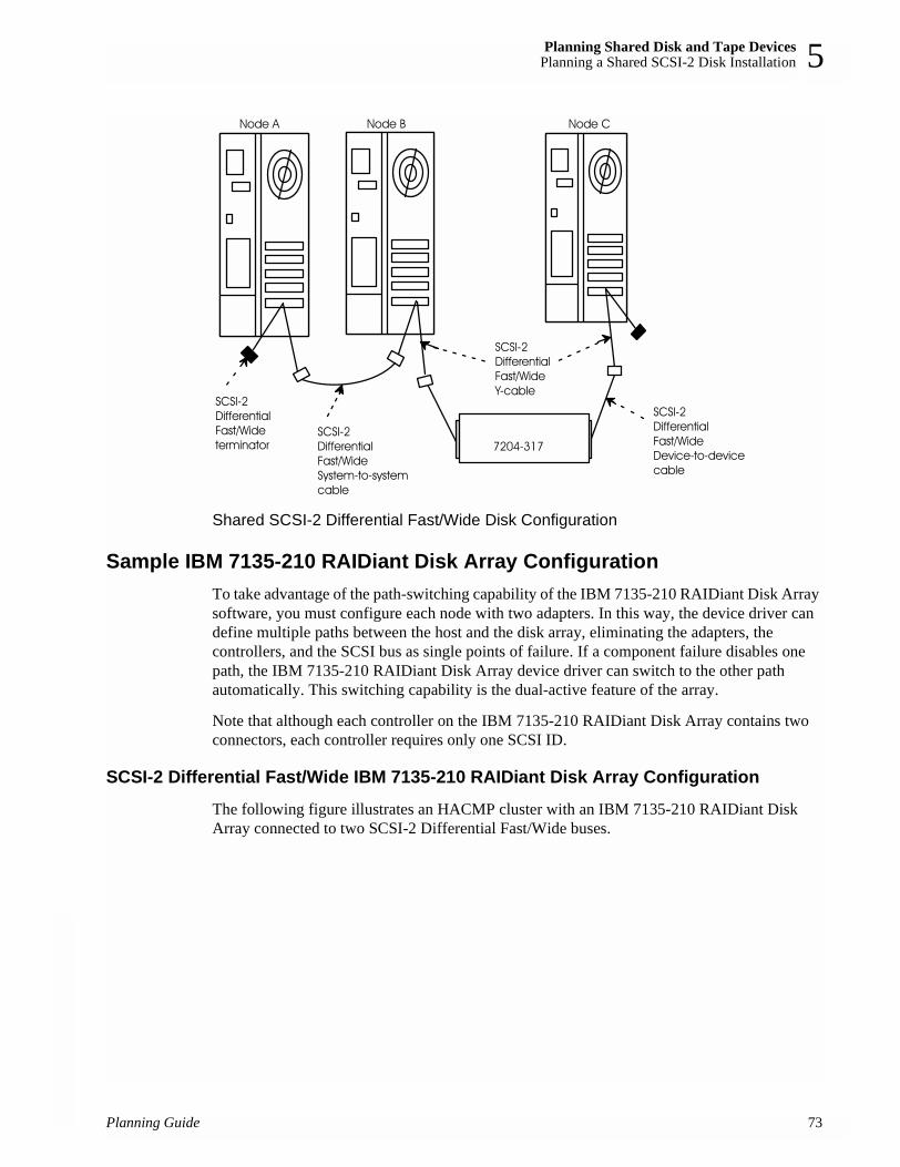
Planning Shared Disk and Tape DevicesPlanning a Shared SCSI-2 Disk Installation 5
Shared SCSI-2 Differential Fast/Wide Disk Configuration
Sample IBM 7135-210 RAIDiant Disk Array ConfigurationTo take advantage of the path-switching capability of the IBM 7135-210 RAIDiant Disk Array software, you must configure each node with two adapters. In this way, the device driver can define multiple paths between the host and the disk array, eliminating the adapters, the controllers, and the SCSI bus as single points of failure. If a component failure disables one path, the IBM 7135-210 RAIDiant Disk Array device driver can switch to the other path automatically. This switching capability is the dual-active feature of the array.
Note that although each controller on the IBM 7135-210 RAIDiant Disk Array contains two connectors, each controller requires only one SCSI ID.
SCSI-2 Differential Fast/Wide IBM 7135-210 RAIDiant Disk Array ConfigurationThe following figure illustrates an HACMP cluster with an IBM 7135-210 RAIDiant Disk Array connected to two SCSI-2 Differential Fast/Wide buses.
Planning Guide 73

Planning Shared Disk and Tape DevicesPlanning a Shared SCSI-2 Disk Installation
74
5
IBM 7135-210 RAIDiant Disk Array Configuration with SCSI-2 Differential Fast/Wide Buses
Planning Guide

Planning Shared Disk and Tape DevicesPlanning a Shared SCSI-2 Disk Installation 5
SCSI-2 Differential Fast/Wide IBM 7137 Disk Array ConfigurationThe following figure illustrates an HACMP cluster with an IBM 7137 Disk Array connected to a SCSI-2 Differential Fast/Wide bus.
IBM 7137 Disk Array with a SCSI-2 Differential Fast/Wide Bus
Note: SCSI-2 Fast/Wide connectors on an IBM 7137 Disk Array are positioned vertically.
Sample IBM 2105 Versatile Storage Server ConfigurationSeveral diagrams are included in the information provided on the IBM web pages. See the list of figures in the attachment guide for the VSS. Look for this and other storage information at:
http://www.storage.ibm.com/
Using VSS Features for High Availability
When using the VSS in an HACMP environment, the following is recommended for high availability:• Use the Sparing function to assign disks as spares and reduce the exposure to data loss.
When the VSS detects that a disk is failing, it transfers the data from the failing disk to a spare device. You are required to specify at least one disk as a spare per drawer; however you can specify two spares to a drawer for increased availability.
• Configure the two host interface cards in a bay to device interface cards in the same bay.
Planning Guide 75

Planning Shared Disk and Tape DevicesPlanning a Shared IBM SSA Disk Subsystem Installation
76
5
• Configure the SCSI ports on the same interface card to the same partition of the VSS.
Planning a Shared IBM SSA Disk Subsystem InstallationThe following discussions of adapters and SSA features for high availability are specific to using SSA disks with HACMP. They supplement the information in the IBM SSA manuals.
IBM Manuals for SSAUse the IBM manuals for:• Rules for connecting SSA drives in loops to nodes• Examples of configurations• Planning charts.
Refer to the IBM SSA support web site, http://www.storage.ibm.com/hardsoft/products/ssa/, for a information covering SSA disk subsystem hardware, SSA adapter hardware, and general SSA reference material.
SSA AdaptersAll the IBM SSA manuals are good sources of information on how to connect SSA disk subsystems to nodes. The following sections offer some additional information.
SSA 4-Port Adapter (Feature Code 6214, Type 4-D)
The 6214 SSA adapter (also called a two-way adapter) can support SSA loops containing up to two adapters per loop. In a high availability environment, then, an SSA loop is limited to one of these two configurations:• One node containing two adapters• Two nodes, each containing one adapter
Because of the limit imposed by the two-way adapter, if you configure both the two-way and the eight-way adapters in one loop, you can use only two adapters.
Enhanced SSA 4-Port Adapter (Feature Code 6216, Type 4-G)The 6216 SSA adapter (also called an eight-way adapter) can support SSA loops containing up to eight eight-way adapters per loop. Most multi-node configurations set up with a minimal number of single points of failure require eight-way adapters.
Identifying AdaptersThe two-way and eight-way adapters look the same, but differ in their microcode. The easiest way to determine which adapter you have installed is to run either of the following commands, which display identifying information about the microcode:lsdev -Cc adapterorlscfg -vl ssax
where x is the adapter number.
Planning Guide

Planning Shared Disk and Tape DevicesPlanning a Shared IBM SSA Disk Subsystem Installation 5
Bypass Cards in the 7133, Models 020 and 600 Disk SubsystemsThe 7133 Models 020 and 600 disk subsystems contain four bypass cards. Each bypass card has two external SSA connectors. Through these, you connect the bypass cards and, therefore, the disk drive module strings to each other or to a node.
Bypass cards maintain high availability when a node fails, when a node is powered off, or when the adapter(s) of a node fail. Connect the pair of ports of one bypass card into the loop that goes to and from one node. That is, connect the bypass card to only one node.
Avoid two possible conditions when a bypass card switches to bypass mode:• Do not connect two independent loops through a bypass card. When the bypass card
switches to bypass mode, you want it to reconnect the loop inside the 7133 disk subsystem, rather than connecting two independent loops. So both ports of the bypass card must be in the same loop.
• Dummy disks are connectors used to fill out the disk drive slots in a 7133 disk subsystem so the SSA loop can continue unbroken. Make sure that when a bypass card switches to bypass mode, it connects no more than three dummy disks consecutively in the same loop. Put the disks next to the bypass cards and dummy disks between real disks.
The bypass cards can operate in either bypass or forced inline mode.
Bypass ModeWhen you set the jumpers on a bypass card so that it operates in bypass mode, the card monitors both of its external connections. If it determines that one of its connectors is connected to a powered-on SSA adapter or device, it switches to inline mode; that is, it connects the internal SSA links to the external connector. This effectively heals the break in the SSA loop.
If the bypass card determines that neither of its connectors is connected to a powered-on SSA adapter or device, it connects the internal disk strings and disconnects them from the external connector.
Forced Inline ModeWhen you set the jumpers on a bypass card so that it operates in forced inline mode, the card behaves like a signal card of Models 010 and 500; that is, none of its electronic switching circuits are used. Its internal SSA links connect to the external connector and never make an internal bypass connection.
Using SSA Features for High AvailabilityThis section describes how you can use SSA features to make your system highly available.
Using SSA Loops
You can set up your configuration so that all SSA devices are in a loop, not just connected in a string. Although SSA devices will function when connected in a string, a loop provides two paths of communications to each device for redundancy. The adapter chooses the shortest path to a disk.
Planning Guide 77

Planning Shared Disk and Tape DevicesPlanning a Shared IBM SSA Disk Subsystem Installation
78
5
Using SSA Fiber-Optic ExtendersThe SSA Fiber-Optic Extenders use cables up to 2.4 Km to replace a single SSA cable. The SSA Fiber-Optic Extender (Feature code 5500) is supported on all Model 7133 disk subsystems.
Using Fiber-Optic extenders, you can make the distance between disks greater than the LAN allows. If you do so, you cannot use routers and gateways. Consequently, under these circumstances, you cannot form an HACMP cluster between two LANs.
Daisy-Chaining the AdaptersIn each node, for each loop including that node, you can daisy-chain all the adapters. The SSAR router device uses another adapter when it detects that one adapter has failed. You need only one bypass switch for the whole daisy chain of adapters in the node rather than a bypass switch for each individual adapter.
Configuring to Minimize Single Points of FailureTo minimize single points of failure, consider the following points:• Use logical volume mirroring and place logical volume mirror copies on separate disks and
in separate loops using separate adapters. In addition, it is a good idea to mirror between the front row and the back row of disks or between disk subsystems.
• The bypass card itself can be single point of failure. Two ways to avoid this are:• With one loop: Put two bypass cards into a loop connecting to each node.• With two loops: Do logical volume mirroring to disks in a second loop. Set each loop
to go through a separate bypass card to each node.• Set the bypass cards to forced inline mode for the following configurations:
• When connecting multiple 7133 disk subsystems.• When the disk drives in one 7133 Model 010 or Model 600 are not all connected to the
same SSA loop. In this type of configuration, forced inline mode removes the risk of a fault condition, namely, that a shift to bypass mode might cause the disk drives of different loops to be connected.
Configuring for Optimal PerformanceThe following guidelines can help you configure your system for optimal performance:• With multiple nodes and SSA domains:
• A node and the disks it accesses make up an SSA domain. For configurations containing shared disk drives and multiple nodes, you need to minimize the path length from each node to the disk drives it accesses. Measure the path length by the number of disk drives and adapters in the path. Each device has to receive and forward the packet of data.
• With multiple adapters in a loop, put the disks near the closest adapter and make that the one that accesses the disks. In effect, try to keep I/O traffic within the SSA domain. Although any host can access any disk it is best to minimize I/O traffic crossing over to other domains.
Planning Guide

Planning Shared Disk and Tape DevicesSSA Disk Fencing in Concurrent Access Clusters 5
• When multiple hosts are in a loop, set up the volume groups so that a node uses the closest disks. This prevents one node’s I/O from interfering with another’s.
• Distribute read and write operations evenly throughout the loops.• Distribute disks evenly among the loops.• Download microcode when you replace hardware.• To ensure that everything works correctly, install the latest filesets, fixes and microcode for
your disk subsystem.• With SSA disk subsystems and concurrent access:
• Once you have decided to use concurrent mode, you may want to plan to be able to replace a failed drive in an SSA concurrent access volume group. To enable this capability, you must assign unique non-zero node numbers on each node of the cluster.
• If you specify the use of SSA disk fencing in your concurrent resource group, HACMP assigns the node numbers when you synchronize the resources.
• If you don’t specify the use of SSA disk fencing in your concurrent resource group, assign the node numbers with:chdev -l ssar -a node_number=x
where x is the number to assign to that node. Then reboot the system.
Note: The ID on a given node should match the HACMP node ID (see the node_id field of the HACMPnode entry). The following command retrieves the HACMP node ID: odmget -q "name = <node_name>"
TestingTest all loop scenarios thoroughly, especially in multiple-node loops. Test for loop breakage (failure of one or more adapters). Test bypass cards for power loss in adapters and nodes to verify that they follow configuration guidelines.
RAID Enabled 7133Certain storage adapters are available with the RS/6000 which provide RAID 5 capability for the 7133. See your IBM product documentation for more information on these adapters. The presence of this adapter will affect how HACMP behaves in specific configurations. See Chapter 6: Planning Shared LVM Components for more information.
SSA Disk Fencing in Concurrent Access ClustersPreventing data integrity problems that can result from the loss of TCP/IP network communication is especially important in concurrent access configurations where multiple nodes have simultaneous access to a shared disk. Chapter 4: Planning Serial Networks, describes using HACMP-specific serial networks to prevent partitioned clusters. Concurrent access configurations using SSA disk subsystems can also use disk fencing to prevent data integrity problems that can occur in partitioned clusters.
Planning Guide 79

Planning Shared Disk and Tape DevicesSSA Disk Fencing in Concurrent Access Clusters
80
5
The SSA disk subsystem includes fence registers (one per disk) capable of permitting or disabling access by each of the eight possible connections. Fencing provides a means of preventing uncoordinated disk access by one or more nodes.
The SSA hardware has a fencing command for automatically updating the fence registers. This command provides a tie-breaking function within the controller for nodes attempting to update the same fence register independently. A compare-and-swap protocol of the fence command requires that each node provide both the current and the desired contents of the fence register. If competing nodes attempt to update a register at about the same time, the first succeeds, but the second fails because it does not know the revised contents.
SSA Disk Fencing Implementation
The HACMP software manages the contents of the fence registers. At cluster configuration, the fence registers for each shared disk are set to allow access for the designated nodes. As cluster membership changes as nodes enter and leave, the event scripts call the cl_ssa_fence utility to update the contents of the fence register. If the fencing command succeeds, the script continues normal processing. If the operation fails, the script exits with a failure status, causing the cluster to go into reconfiguration.
The Installation Guide describes enabling SSA disk fencing for an HACMP cluster. The Administration Guide provides additional information about disk fencing.
Disk Fencing with SSA Disks in Concurrent ModeYou can only use SSA disk fencing under these conditions: • Only disks contained in concurrent mode volume groups will be fenced.• You configure all nodes of the cluster to have access to these disks and to use disk fencing.• All resource groups with the disk fencing attribute enabled must be concurrent access
resource groups.• Concurrent access resource groups must contain all nodes in the cluster.
The purpose of SSA disk fencing is to provide a safety lockout mechanism for protecting shared SSA disk resources in the event that one or more cluster nodes become isolated from the rest of the cluster.
Concurrent mode disk fencing works as follows:• The first node up in the cluster fences out all other nodes of the cluster from access to the
disks of the concurrent access volume group(s) for which fencing is enabled, by changing the fence registers of these disks.
• When a node joins a cluster, the active nodes in the cluster allow the joining node access by changing the fence registers of all disks participating in fencing with the joining node.
• When a node leaves the cluster, regardless of how it leaves, the remaining nodes that share access to a disk with the departed node should fence out the departed node as soon as possible.
• If a node is the last to leave a cluster, whether the shutdown is forced or graceful, it clears the fence registers to allow access by all nodes. Of course, if the last node stops unexpectedly (is powered off or crashes, for example), it doesn’t clear the fence registers. In this case, you must manually clear the fence registers using the proper SMIT options.
Planning Guide

Planning Shared Disk and Tape DevicesSSA Disk Fencing in Concurrent Access Clusters 5
Enabling SSA Disk FencingThe process of enabling SSA disk fencing for a concurrent resource group requires that all volume groups containing SSA disks on cluster nodes must be varied off and the cluster must be down when the cluster resources are synchronized. Note that this means all volume groups containing any of the SSA disks whether concurrent or non-concurrent, whether configured as part of the cluster or not, must be varied off for the disk fencing enabling process to succeed during the synchronization of cluster resources. If these conditions are not met, you will have to reboot the nodes to enable fencing.
The enabling process takes place on each cluster node: as follows:
1. Assign a node_number to the ssar which matches the node_id of the node in the HACMP configuration. This means that any node_numbers, that were set prior to enabling disk fencing for purposes of replacing a drive or C-SPOC concurrent LVM functions, will be changed for disk fencing operations. The other operations will not be affected by this node_number change.
2. First remove, then remake all hdisks, pdisks, ssa adapter, and tmssa devices of the SSA disk subsystem seen by the node, thus picking up the node_number for use in the fence register of each disk.
This process is repeated each time cluster resources are synchronized while the cluster is down.
Disk Fencing and Dynamic ReconfigurationWhen a node is added to the cluster through dynamic reconfiguration while cluster nodes are up, the disk fencing enabling process is performed on the added node only, during the synchronizing of topology. Any node_numbers that were set prior to enabling disk fencing for purposes of replacing a drive or C-SPOC concurrent LVM functions will be changed for disk fencing operations. Therefore, when initially setting SSA disk fencing in a resource group, the resources must be synchronized while the cluster is down. The other operations will not be affected by this node_number change.
Benefits of Disk FencingDisk fencing provides the following benefits to concurrent access clusters:• It enhances data security by preventing nodes that are not active members of a cluster from
modifying data on a shared disk. By managing the fence registers, the HACMP software can ensure that only the designated nodes within a cluster have access to shared SSA disks.
• It enhances data reliability by assuring that competing nodes do not compromise the integrity of shared data. By managing the fence registers HACMP can prevent uncoordinated disk management by partitioned clusters. In a partitioned cluster, communication failures lead separate sets of cluster nodes to believe they are the only active nodes in the cluster. Each set of nodes attempts to take over the shared disk, leading to race conditions. The disk fencing tie-breaking mechanism arbitrates race conditions, ensuring that only one set of nodes gains access to the disk.
Planning Guide 81

Planning Shared Disk and Tape DevicesCompleting the Disk Worksheets
82
5
Completing the Disk Worksheets After determining the disk storage technology you will include in your cluster, complete all of the appropriate worksheets from the following list: • Shared SCSI-2 Differential or Differential Fast/Wide Disk Worksheet• Shared SCSI Disk Array Worksheet• Shared IBM Serial Storage Architecture Disk Subsystems Worksheet
Completing the Shared SCSI-2 Disk WorksheetComplete a worksheet in Appendix A for each shared SCSI bus.
1. Enter the cluster ID and the Cluster name in the appropriate fields. This information was determined in Chapter 2: Drawing the Cluster Diagram.
2. Check the appropriate field for the type of SCSI-2 bus.
3. Fill in the host and adapter information including the node name, the number of the slot in which the disk adapter is installed and the logical name of the adapter, such as scsi0. AIX assigns the logical name when the adapter is configured.
4. Determine the SCSI IDs for all the devices connected to the SCSI bus.
5. The IBM SCSI-2 Differential High Performance Fast/Wide adapter cannot be assigned SCSI IDs 0, 1, or 2.
6. Record information about the Disk drives available over the bus, including the logical device name of the disk on every node. (This name, an hdisk name, is assigned by AIX when the device is configured and may vary on each node.)
Completing the Shared SCSI-2 Disk Array WorksheetComplete a worksheet in Appendix A for each shared SCSI disk array.
1. Enter the cluster ID and the Cluster name in the appropriate fields. This information was determined in Chapter 2: Drawing the Cluster Diagram.
2. Fill in the host and adapter information including the node name, the number of the slot in which the disk adapter is installed and the logical name of the adapter, such as scsi0. AIX assigns the logical name when the adapter is configured.
3. Assign SCSI IDs for all the devices connected to the SCSI bus. For disk arrays, the controller on the disk array are assigned the SCSI ID.
4. Record information about the LUNs configured on the disk array.
5. Record the logical device name AIX assigned to the array controllers when it was configured. If you have configured an IBM RAIDiant disk array, you can optionally configure the REACT software that configures a pseudo-device called a Disk Array Router.
Completing the IBM SSA Disk Subsystems WorksheetComplete a worksheet in Appendix A for each shared SSA configuration.
Planning Guide

Planning Shared Disk and Tape DevicesAdding the Disk Configuration to the Cluster Diagram 5
1. Enter the cluster ID and the Cluster name in the appropriate fields. This information was determined in Chapter 2: Drawing the Cluster Diagram.
2. Fill in the host and adapter information including the node name, the SSA adapter label, and the number of the slot in which the disk adapter is installed. Include dual-port number of the connection. This will be needed to make the loop connection clear.
3. Determine the SCSI IDs for all the devices connected to the SCSI bus.
Adding the Disk Configuration to the Cluster DiagramOnce you have chosen a disk technology, draw a diagram that shows the shared disk configuration. Be sure to include adapters and cables in the diagram. You may be able to expand on the cluster diagram you began in Chapter 2: Drawing the Cluster Diagram, or you may need to have a separate diagram (for the sake of clarity) that shows the shared disk configuration for the cluster.
Planning for Tape Drives as Cluster ResourcesYou can configure a tape drive as a cluster resource, making it highly available to multiple nodes in a cluster. SCSI streaming tape drives and direct fibre channel tape unit attachments are supported. Management of shared tape drives is simplified by the following HACMP functionality:• Configuration of tape drives using SMIT• Verification of proper configuration of tape drives• Automatic management of tape drives during resource group start and stop operations• Reallocation of tape drives on node failure and node recovery• Controlled reallocation of tape drives on cluster shutdown• Controlled reallocation of tape drives during DARE migration.
LimitationsNote the following as you plan to include tape drives as cluster resources:• Support is limited to SCSI or Fibre Channel tape drives which have hardware reserve and
hardware reset/release functions.• Tape loaders/stackers are not supported.• No more than two cluster nodes can share the tape resource.• Tape resources may not be part of concurrent resource groups.• The tape drive must have the same name, i.e. /dev/rmt0, on both nodes sharing the tape
device.• When a tape special file is closed, the default action is to release the tape drive. HACMP is
not responsible for the state of the tape drive once an application has opened the tape.• No means of synchronizing tape operations and application servers is provided. If you
decide that a tape reserve/release should be done asynchronously, then you must provide a way to notify the application server to wait until the reserve/release is complete.
Planning Guide 83

Planning Shared Disk and Tape DevicesPlanning for Tape Drives as Cluster Resources
84
5
• Tape drives with more than one SCSI interface are not supported. Therefore, only one connection exists between a node and a tape drive. The usual notion of adapter fallover does not apply.
Reserving and Releasing Shared Tape DrivesWhen a resource group with tape resources is activated, the tape drive is reserved to allow its exclusive use. This reservation is held until an application releases it, or the node is removed from the cluster.• When the special file for the tape is closed, the default action is to release the tape drive.
An application can open a tape drive with a “do not release on close” flag. HACMP will not be responsible for maintaining the reservation after an application is started.
• Upon graceful shutdown of a node the tape drive will be released, allowing access from other nodes.
• Upon unexpected node failure, a forced release will be done on the takeover node. The tape drive will then be reserved as part of resource group activation.
Setting Tape Drives to Synchronous or Asynchronous OperationIf a tape operation is in progress when a tape reserve or release is initiated, it may take many minutes before the reserve or release operation completes. HACMP allows synchronous or asynchronous reserve and release operations. Synchronous and asynchronous operation is specified separately for reserve and release.
SynchronousWith synchronous operation (the default value), HACMP waits for the reserve or release operation, including the execution of a user defined recovery procedure, to complete before continuing.
AsynchronousWith asynchronous operation, HACMP creates a child process to perform the reserve or release operation, including the execution of a user defined recovery procedure, and immediately continues.
Recovery ProceduresRecovery procedures are highly dependent on the application accessing the tape drive. Rather than trying to predict likely scenarios and develop recovery procedures, HACMP provides for the execution of user defined recovery scripts for the following:• Tape start• Tape stop.
Tape Start/Stop ScriptsTape start and stop occurs during node start and stop, node fallover and reintegration, and dynamic reconfiguration. These scripts are invoked when a resource group is activated (tape start) or when a resource group is deactivated (tape stop). Sample start and stop scripts can be found in the /usr/sbin/cluster/samples/tape directory:tape_resource_start_example tape_resource_stop_example
Planning Guide

Planning Shared Disk and Tape DevicesWhere You Go From Here 5
• During tape start, HACMP reserves the tape drive, forcing a release if necessary, and then invokes the user-provided tape start script.
• During tape stop, HACMP invokes the user-provided tape stop script, and then releases the tape drive.
Note: You are responsible for correctly positioning the tape, terminating processes or applications writing to the tape drive, writing end of tape marks, etc., within these scripts.
Other application-specific procedures should be included as part of the start server and stop server scripts, which can be specified in the Define Application Servers SMIT screen.
Adapter Fallover and RecoveryTape drives with more than one SCSI interface are not supported. Therefore, only one connection exists between a node and a tape drive. The usual notion of adapter fallover does not apply.
However, a network service adapter is generally associated with a resource group. Failure of the service adapter causes the standby adapter, if available, to become the service adapter. Recovery procedures, if necessary, is the responsibility of the application. HACMP does not reserve or release the tape drive during network adapter fallover.
Node Fallover and RecoveryIf a node which has tape resources that are part of a HACMP resource group fails, the takeover node will reserve the tape drive, forcing a release if necessary, and then invoke the user-provided tape start script.
On reintegration of a node with cascading resources, the takeover node runs the tape stop script and then releases the tape drive. The node being reintegrated reserves the tape drive and invokes the user-provided tape start script.
Network Fallover and Recovery
HACMP does not provide tape fallover/recovery procedures for network failure.
Completing the Shared Tape Drive WorksheetSee the section on installing tape drives in the Installation Guide for the information to put in the worksheet. The worksheets are in Appendix A of this Guide.
Where You Go From HereYou have now planned your shared disk configuration. The next step is to plan the shared volume groups for your cluster. This step is described in Chapter 6: Planning Shared LVM Components.
Planning Guide 85

Planning Shared Disk and Tape DevicesWhere You Go From Here
86
5
Planning Guide
Planning Shared LVM ComponentsPrerequisites 6
Chapter 6: Planning Shared LVM ComponentsThis chapter describes planning shared volume groups for an HACMP cluster.
PrerequisitesBefore reading this chapter, you must have decided which method of shared disk access—non-concurrent or concurrent—you are going to use. Read the Concepts and Facilities guide and Chapter 2: Drawing the Cluster Diagram in this guide for a discussion of the shared disk access methods supported by the HACMP software.
This chapter discusses Logical Volume Manager (LVM) issues as they relate to the HACMP environment. It does not provide an exhaustive discussion of LVM concepts and facilities in general. Read the chapters on logical volumes, filesystems, paging spaces, and backups in the AIX 5L Version 5.1 System Management Guide: Operating System and Devices for more information on the AIX LVM. This and other AIX 5L manuals can be found online at http://publibn.boulder.ibm.com/cgi-bin/ds_rslt#1
OverviewPlanning shared LVM components for an HACMP cluster differs depending on the method of shared disk access and the type of shared disk device. This discussion assumes the goal of no single point of failure. Mirroring should always be used, especially where the power supply of a controller is an issue.
This chapter presents information necessary for both methods of shared disk access and points out differences where applicable. After presenting various planning considerations and guidelines, this chapter provides instruction for completing the shared LVM components worksheets for the appropriate method of shared disk access.
Planning for Non-Concurrent AccessNon-concurrent access configurations typically use journaled filesystems. (In some cases, a database application running in a non-concurrent environment may bypass the journaled filesystem and access the raw logical volume directly.) Non-concurrent access configurations that use SCSI disks, including IBM 7137 Disk Arrays, can use AIX LVM mirroring.
Non-concurrent access configurations that use IBM 7135-110, 7135-210 RAIDiant Disk Arrays, IBM 2105-B09, 2105-100 Versatile Storage Servers, IBM 2105-E10 and E-20 Enterprise Storage Servers, or the 7133 SSA with RAID enabled do not use LVM mirroring. These systems provide their own data redundancy.
Planning Guide 87

Planning Shared LVM ComponentsLVM Components in the HACMP Environment
88
6
Planning for Concurrent AccessConcurrent access configurations do not support journaled filesystems. Concurrent access configurations that use IBM 7131-405 and 7133 SSA disk subsystems, and the 7137 Disk Array should use LVM mirroring. Concurrent access configurations that use IBM 7135-110, 7135-210 RAIDiant Disk Arrays, or IBM 2105 Versatile and Enterprise Storage Servers do not use LVM mirroring. These systems provide their own data redundancy.
LVM Components in the HACMP EnvironmentThe LVM controls disk resources by mapping data between physical and logical storage. Physical storage refers to the actual location of data on a disk. Logical storage refers to how data is made available to the user. Logical storage can be discontiguous, expanded, or replicated, and can span multiple physical disks. The combination of physical and logical storage provides improved availability of data.
The LVM organizes data into the following components:• Physical volumes• Volume groups• Logical volumes• Filesystems
Considerations for each component as it relates to planning an HACMP cluster are discussed in the following sections.
Physical VolumesA physical volume is a single physical disk. Physical volumes are divided into physical partitions, and are known to AIX by assigned hdisk numbers.
Physical PartitionsThe physical volume is partitioned to provide AIX with a way of managing how data is mapped to the volume. The following figure shows how the physical partitions within a physical volume are conventionally diagrammed:
Physical Partitions on a Physical Volume
Planning Guide

Planning Shared LVM ComponentsLVM Components in the HACMP Environment 6
hdisk NumbersPhysical volumes are known in the AIX operating system by sequential hdisk numbers assigned when the system boots. For example, /dev/hdisk0 identifies the first physical volume in the system, /dev/hdisk1 identifies the second physical volume in the system, and so on.
When sharing a disk in an HACMP cluster, the nodes sharing the disk each assign an hdisk number to that disk. These hdisk numbers may not match across nodes, yet they still refer to the same physical volume. For example, each node may have a different number of internal disks, or the disks may have changed since AIX was installed.
The HACMP software does not require that the hdisk numbers match across nodes (although a system is easier to manage if they do). In situations where the hdisk numbers must differ, make sure that you understand each node’s view of the shared disks. Draw a diagram that indicates the hdisk numbers that each node assigns to the shared disks and record these numbers on the appropriate volume group worksheets in Appendix A: Planning Worksheets. When in doubt, use the hdisk’s Physical Volume ID (PVID) to verify its identity on a shared bus.
Use the lspv command to get the PVIDs.
Volume GroupsA volume group is a set of physical volumes that AIX treats as a contiguous, addressable disk region. You can place from 1 to 32 physical volumes in the same volume group.
The following figure shows a volume group of three physical volumes:
A Volume Group of Three Physical Volumes
Shared Volume GroupsIn the HACMP environment, a shared volume group is a volume group that resides entirely on the external disks shared by the cluster nodes. Do not include an internal disk in a shared volume group, since it cannot be accessed by other nodes. If you include an internal disk in a shared volume group, the varyonvg command fails.
The name of a shared volume group must be unique. It cannot conflict with the name of an existing volume group on any node in the cluster.
In non-concurrent access environments, a shared volume group can be varied on by only one node at a time. In concurrent access environments, multiple nodes can have the volume group varied on (activated) at the same time.
As a general rule, the shared volume groups in an HACMP cluster should not be varied on automatically at system boot, but should be activated by cluster event scripts.
Planning Guide 89

Planning Shared LVM ComponentsLVM Mirroring
90
6
In a non-concurrent access configuration, each volume group that has filesystems residing on it has a log logical volume (jfslog) that must also have a unique name.
Logical VolumesA logical volume is a set of logical partitions that AIX makes available as a single storage unit—that is, the logical volume is the “logical view” of a physical disk. Each logical partition is the logical view of a physical partition. Logical partitions may be mapped to one, two, or three physical partitions to implement mirroring.
In the HACMP environment, logical volumes can be used to support a journaled filesystem (non-concurrent access) or a raw device (concurrent access). Concurrent access does not support filesystems. Databases and applications in concurrent access environments must access raw logical volumes (for example, /dev/rsharedlv).
Shared Logical VolumesA shared logical volume must have a unique name within an HACMP cluster. By default, AIX assigns a name to any logical volume that is created as part of a journaled filesystem (for example, lv01). If you rely on the system-generated logical volume name, this name could cause the import to fail when you attempt to import the volume group containing the logical volume into another node’s ODM structure, especially if that volume group already exists. The Installation Guide describes how to change the name of a logical volume.
FilesystemsA filesystem is written to a single logical volume. Ordinarily, you organize a set of files as a filesystem for convenience and speed in managing data.
Shared FilesystemsIn the HACMP system, a shared filesystem is a journaled filesystem that resides entirely in a shared logical volume.
For non-concurrent access, you want to plan shared filesystems to be placed on external disks shared by cluster nodes. Data resides in filesystems on these external shared disks in order to be made highly available.
For concurrent access, you cannot use journaled filesystems. Instead, you must use raw logical volumes.
LVM MirroringNote: This section does not apply to the IBM 7135-110, 7135-210 RAIDiant
Disk Arrays, IBM 2105-B09, 2105-100 Versatile Storage Servers, IBM 2105-E10, 2105-E20 Enterprise Storage Servers, or 7133 SSA with RAID enabled, which provide their own data redundancy.
Planning Guide
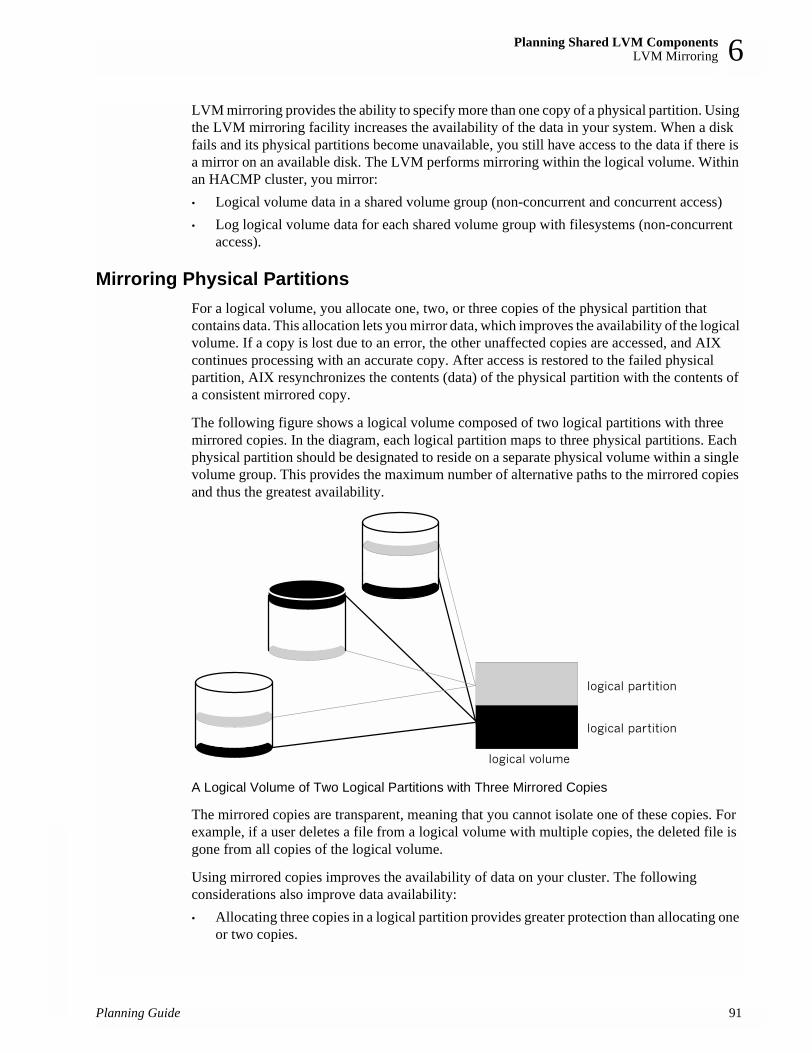
Planning Shared LVM ComponentsLVM Mirroring 6
LVM mirroring provides the ability to specify more than one copy of a physical partition. Using the LVM mirroring facility increases the availability of the data in your system. When a disk fails and its physical partitions become unavailable, you still have access to the data if there is a mirror on an available disk. The LVM performs mirroring within the logical volume. Within an HACMP cluster, you mirror:• Logical volume data in a shared volume group (non-concurrent and concurrent access)• Log logical volume data for each shared volume group with filesystems (non-concurrent
access).
Mirroring Physical Partitions For a logical volume, you allocate one, two, or three copies of the physical partition that contains data. This allocation lets you mirror data, which improves the availability of the logical volume. If a copy is lost due to an error, the other unaffected copies are accessed, and AIX continues processing with an accurate copy. After access is restored to the failed physical partition, AIX resynchronizes the contents (data) of the physical partition with the contents of a consistent mirrored copy.
The following figure shows a logical volume composed of two logical partitions with three mirrored copies. In the diagram, each logical partition maps to three physical partitions. Each physical partition should be designated to reside on a separate physical volume within a single volume group. This provides the maximum number of alternative paths to the mirrored copies and thus the greatest availability.
A Logical Volume of Two Logical Partitions with Three Mirrored Copies
The mirrored copies are transparent, meaning that you cannot isolate one of these copies. For example, if a user deletes a file from a logical volume with multiple copies, the deleted file is gone from all copies of the logical volume.
Using mirrored copies improves the availability of data on your cluster. The following considerations also improve data availability:• Allocating three copies in a logical partition provides greater protection than allocating one
or two copies.
Planning Guide 91

Planning Shared LVM ComponentsQuorum
92
6
• Allocating the copies of a logical partition on different physical volumes provides greater protection than allocating the copies on the same physical volume.
• Allocating the copies of a logical partition on different disk adapters provides greater protection than allocating the copies on a single disk adapter.
Keep in mind that anything that improves availability may increase the time necessary for write operations. Nevertheless, using mirrored copies spanning multiple disks (on separate power supplies) together with multiple adapters ensures that no disk is a single point of failure for your cluster.
Mirroring Journal LogsThis section applies to non-concurrent access configurations, which support journaled filesystems.
AIX uses journaling for its filesystems. In general, this means that the internal state of a filesystem at startup (in terms of the block list and free list) is the same as at shutdown. In practical terms, this means that when AIX starts up, the extent of any file corruption can be no worse than at shutdown.
Each volume group contains a jfslog, which is itself a logical volume. This log typically resides on a different physical disk in the volume group than the journaled filesystem. If access to the disk containing the jfslog is lost, however, changes to filesystems after that point are in jeopardy.
To avoid the possibility of that physical disk being a single point of failure, you can specify mirrored copies of each jfslog. Place these copies on separate physical volumes.
QuorumNote: This section does not apply to the IBM 7135-110,7135-210 RAIDiant
Disk Arrays or IBM 2105 Versatile and Enterprise Storage Servers, or 7133 SSA with RAID enabled, which provide their own data redundancy.
Quorum is a feature of the AIX LVM that determines whether or not a volume group can be placed online using the varyonvg command, and whether or not it can remain online after a failure of one or more of the physical volumes in the volume group.
Each physical volume in a volume group has a Volume Group Descriptor Area (VGDA) and a Volume Group Status Area (VGSA).
VGDA Describes the physical volumes (PVs) and logical volumes (LVs) that make up a volume group and maps logical partitions to physical partitions. The varyonvg command reads information from this area.
VGSA Maintains the status of all physical volumes and physical partitions in the volume group. It stores information regarding whether a physical partition is potentially inconsistent (stale) with mirror copies on other physical partitions, or is consistent or synchronized with its mirror copies. Proper functioning of LVM mirroring relies upon the availability and accuracy of the VGSA data.
Planning Guide

Planning Shared LVM ComponentsQuorum 6
Quorum at Vary OnWhen a volume group is brought online using the varyonvg command, VGDA and VGSA data structures are examined. If more than half of the copies are readable and identical in content, quorum is achieved and the varyonvg command succeeds. If exactly half the copies are available, as with two of four, quorum is not achieved and the varyonvg command fails.
Quorum after Vary OnIf a write to a physical volume fails, the VGSAs on the other physical volumes within the volume group are updated to indicate that one physical volume has failed. As long as more than half of all VGDAs and VGSAs can be written, quorum is maintained and the volume group remains varied on. If exactly half or less than half of the VGDAs and VGSAs are inaccessible, quorum is lost, the volume group is varied off, and its data becomes unavailable.
Keep in mind that a volume group can be varied on or remain varied on with one or more of the physical volumes unavailable. However, data contained on the missing physical volume will not be accessible unless the data is replicated using LVM mirroring and a mirror copy of the data is still available on another physical volume. Maintaining quorum without mirroring does not guarantee that all data contained in a volume group is available.
Quorum has nothing to do with the availability of mirrored data. It is possible to have failures that result in loss of all copies of a logical volume, yet the volume group remains varied on because a quorum of VGDAs/VGSAs are still accessible.
Disabling and Enabling QuorumQuorum checking is enabled by default. Quorum checking can be disabled using the chvg -Qn vgname command, or by using the smit chvg fastpath.
Quorum EnabledWith quorum enabled, more than half of the physical volumes must be available and the VGDA and VGSA data structures must be identical before a volume group can be varied on with the varyonvg command.
With quorum enabled, a volume group will be forced offline if one or more disk failures cause a majority of the physical volumes to be unavailable. Having three or more disks in a volume group avoids a loss of quorum in the event of a single disk failure.
Quorum Disabled
With quorum disabled, all the physical volumes in the volume group must be available and the VGDA data structures must be identical for the varyonvg command to succeed. With quorum disabled, a volume group will remain varied on until the last physical volume in the volume group becomes unavailable. This section summarizes the effect quorum has on the availability of a volume group.
Planning Guide 93

Planning Shared LVM ComponentsQuorum
94
6
Forcing a VaryonA volume group with quorum disabled and one or more physical volumes unavailable can be “forced” to vary on by using the -f flag with the varyonvg command. Forcing a varyon with missing disk resources could cause unpredictable results, including a reducevg of the physical volume from the volume group. Forcing a varyon should be an overt (manual) action and should only be performed with a complete understanding of the risks involved.
The HACMP software assumes that a volume group is not degraded and all physical volumes are available when the varyonvg command is issued at startup or when a volume group resource is taken over during a fallover. The cluster event scripts provided with the HACMP software do not “force” varyon with the -f flag, which could cause unpredictable results. For this reason, modifying the cluster event scripts to use the -f flag is strongly discouraged.
Quorum in Non-Concurrent Access ConfigurationsWhile specific scenarios can be constructed where quorum protection does provide some level of protection against data corruption and loss of availability, quorum provides very little actual protection in non-concurrent access configurations. In fact, enabling quorum may mask failures by allowing a volume group to varyon with missing resources. Also, designing logical volume configuration for no single point of failure with quorum enabled may require the purchase of additional hardware. On the other hand, you must keep in mind that disabling quorum can result in a subsequent loss of disks—after varying on the volume group—that goes undetected.
Often it is not practical to configure disk resources as shown in the following figure because of the expense. Take, for example, a cluster that requires 8 GB of disk storage (4 GB double mirrored). This requirement could be met with two IBM disk subsystems and two disk adapters in each node. For data availability reasons, logical volumes would be mirrored across disk subsystems.
A Sample Non-Concurrent HACMP Configuration
With quorum enabled, the failure of a single adapter, cable, or disk subsystem power supply would cause exactly half the disks to be inaccessible. Quorum would be lost and the volume group varied off even though a copy of all mirrored logical volumes is still available. One solution is to turn off quorum checking for the volume group. The trade-off is that, with quorum disabled, all physical volumes must be available for the varyonvg command to succeed.
adapter adapter
Disk 1Disk 2Disk 3Disk 4
Disk 5Disk 6Disk 7Disk 8
Node A Node B
adapter adapter
Planning Guide
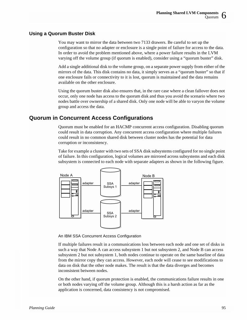
Planning Shared LVM ComponentsQuorum 6
Using a Quorum Buster DiskYou may want to mirror the data between two 7133 drawers. Be careful to set up the configuration so that no adapter or enclosure is a single point of failure for access to the data. In order to avoid the problem mentioned above, where a power failure results in the LVM varying off the volume group (if quorum is enabled), consider using a “quorum buster” disk.
Add a single additional disk to the volume group, on a separate power supply from either of the mirrors of the data. This disk contains no data, it simply serves as a “quorum buster” so that if one enclosure fails or connectivity to it is lost, quorum is maintained and the data remains available on the other enclosure.
Using the quorum buster disk also ensures that, in the rare case where a clean fallover does not occur, only one node has access to the quorum disk and thus you avoid the scenario where two nodes battle over ownership of a shared disk. Only one node will be able to varyon the volume group and access the data.
Quorum in Concurrent Access ConfigurationsQuorum must be enabled for an HACMP concurrent access configuration. Disabling quorum could result in data corruption. Any concurrent access configuration where multiple failures could result in no common shared disk between cluster nodes has the potential for data corruption or inconsistency.
Take for example a cluster with two sets of SSA disk subsystems configured for no single point of failure. In this configuration, logical volumes are mirrored across subsystems and each disk subsystem is connected to each node with separate adapters as shown in the following figure.
An IBM SSA Concurrent Access Configuration
If multiple failures result in a communications loss between each node and one set of disks in such a way that Node A can access subsystem 1 but not subsystem 2, and Node B can access subsystem 2 but not subsystem 1, both nodes continue to operate on the same baseline of data from the mirror copy they can access. However, each node will cease to see modifications to data on disk that the other node makes. The result is that the data diverges and becomes inconsistent between nodes.
On the other hand, if quorum protection is enabled, the communications failure results in one or both nodes varying off the volume group. Although this is a harsh action as far as the application is concerned, data consistency is not compromised.
Planning Guide 95

Planning Shared LVM ComponentsUsing NFS with HACMP
96
6
Using NFS with HACMPIn HACMP versions 4.4.0 and up, functionality previously available only in the separate High Availability for Network File System (HANFS) product has been added to the basic HACMP architecture. The following enhancements are included: • Reliable NFS server capability that allows a backup processor to recover current NFS
activity should the primary NFS server fail, preserving the locks on NFS filesystems and dupcache. This functionality is available for two-node clusters only.
• Ability to specify a network for NFS mounting.• Ability to define NFS exports and mounts at the directory level.• Ability to specify export options for NFS-exported directories and filesystems.
In order for NFS to work as expected on an HACMP cluster, you must be aware of certain configuration issues, so you can plan accordingly: • Creating shared volume groups• Exporting NFS filesystems• NFS mounting and fallover.
The HACMP scripts have only minimal NFS support. You may need to modify them to handle your particular configuration. The following sections contain some suggestions for planning for a variety of NFS-related issues.
Reliable NFS Server CapabilityAn HACMP two-node cluster can take advantage of AIX extensions to the standard NFS functionality that enable it to handle duplicate requests correctly and restore lock state during NFS server fallover and reintegration. This support was previously only available in the HANFS feature.
Though HACMP itself has no dependency on the hostname, the NFS rpc.statd daemon uses the hostname (actually “uname -n” value) of clients and servers in storing lock information. Therefore, in two-node clusters that export filesystems, where preservation of locks is important, the hostname (uname) must be associated with an IP label that will not change while the system is operational.
For rotating configurations, IP address takeover (IPAT) occurs on the service adapter. The hostname (uname), therefore, must be associated with the standby IP address on each node (or some other active IP address not even defined to HACMP). For cascading configurations, IPAT occurs on the standby adapter. Thus the hostname (uname) must be associated with the service IP address. In both configurations, the hostname (uname) can be a second label associated with the proper IP address for the service or standby adapter.
Creating Shared Volume Groups with NFSWhen creating shared volume groups, normally you can leave the Major Number field blank and let the system provide a default for you. However, if you are using NFS, all nodes in your cluster must have identical major numbers, as HACMP uses the major number as part of the file handle to uniquely identify a network filesystem.
Planning Guide

Planning Shared LVM ComponentsUsing NFS with HACMP 6
In the event of node failure, NFS clients attached to an HACMP cluster operate exactly the way they do when a standard NFS server fails and reboots. If the major numbers are not the same, when another cluster node takes over the filesystem and re-exports the filesystem, the client application will not recover, since the filesystem exported by the node will appear to be different from the one exported by the failed node.
NFS-Exporting Filesystems and DirectoriesThe process of NFS-exporting filesystems and directories in HACMP is different from that in AIX. Remember the following when planning for NFS-exporting in HACMP:• In AIX, you specify filesystems and directories to NFS-export by using the smit mknfsexp
command (which creates the /etc/exports file). In HACMP, you specify filesystems and directories to NFS-export by adding them to a resource group in the NFS Filesystems/Directories to export field in the HACMP SMIT screen.
• If you want to specify special options for NFS-exporting filesystems and directories in HACMP, you can create a /usr/sbin/cluster/etc/exports file. This file has the same format as the regular AIX /etc/exports file. Note that use of this alternate exports file is optional. HACMP checks the /usr/sbin/cluster/etc/exports file when NFS-exporting a filesystem or directory. If there is an entry for the filesystem or directory in this file, HACMP will use the options listed. If the filesystem or directory for NFS-export is not listed in the file, or, if the alternate file does not exist, the filesystem or directory will be NFS-exported with the default option of root access for all cluster nodes.
• A resource group that specifies filesystems to export should also have the Filesystems Mounted before IP Configured field of the resource group set to true. This ensures that all IP address takeover is performed after exporting the filesystems. If the IP address were managed first, the NFS server would reject client requests until the filesystems had been exported.
Cascading Takeover with Cross Mounted NFS FilesystemsThis section describes how to set up cascading resource groups with cross mounted NFS filesystems so that NFS filesystems are handled correctly during takeover and reintegration.
Only cascading resource groups support automatic NFS mounting across servers during fallover. Rotating resource groups do not provide this support. Instead, you must use additional post-event scripts or perform NFS mounting using normal AIX routines.
For NFS mounting to work properly, a resource group must be configured with traditional IPAT.
Creating NFS Mount Points on Clients
A mount point is required in order to mount a filesystem via NFS. In a cascading resource group, all the nodes in the resource group will NFS mount the filesystem; thus you must create a mount point on each node in the resource group. On each of these nodes, create a mount point by executing the following command:mkdir /<mountpoint>
where mountpoint is the name of the local mountpoint over which the remote filesystem will be mounted.
Planning Guide 97

Planning Shared LVM ComponentsUsing NFS with HACMP
98
6
Setting Up NFS Mount Point Different from Local Mount PointHACMP handles NFS mounting in cascading resource groups as follows: The node that currently owns the resource group will mount the filesystem over the filesystem’s local mount point, and this node will NFS export the filesystem. All the nodes in the resource group (including the current owner of the group) will NFS mount the filesystem over a different mount point. Therefore, the owner of the group will have the filesystem mounted twice—once as a local mount, and once as an NFS mount.Since IPAT is used in resource groups that have NFS mounted filesystems, the nodes will not unmount and remount NFS filesystems in the event of a fallover. When the resource group falls over to a new node, the acquiring node will locally mount the filesystem and NFS-export it. (The NFS mounted filesystem will be temporarily unavailable to cluster nodes during fallover.) As soon as the new node acquires the IPAT label, access to the NFS filesystem is restored.All applications must reference the filesystem through the NFS mount. If the applications are dependent on always referencing the filesystem by the same mount point name, you can change the mount point for the local filesystem mount (for example, change it to mount point_local, and use the previous local mount point as the new NFS mount point).
In the Change/Show Resources/Attributes for a Resource Group SMIT screen, the Filesystem to NFS Mount field must specify both mount points. Put the nfs mount point, then the local mount point, separating the two with a semicolon, for example, “nfspoint;localpoint.” If there are more entries, separate them with a space:
nfspoint1;local1 nfspoint2;local2
If there are nested mount points, the nfs mount points should be nested in the same manner as the local mount points so that they match up properly. When cross mounting NFS filesystems, you must also set the Filesystems Mounted Before IP Configured field of the Resource Group to true.
Server-to-Server NFS Cross Mounting: ExampleHACMP allows you to configure a cluster so that servers can NFS-mount each other’s filesystems. Configuring cascading resource groups allows the Cluster Manager to decide which node should take over a failed resource, based on priority and node availability.
Ensure that the shared volume groups have the same major number on the server nodes. This allows the clients to reestablish the NFS-mount transparently after the takeover.
The example cluster shown below has two resource groups, NodeA_rg and NodeB_rg configured to allow NFS cross mounting.
NodeA_rg DefinitionNodeA_rg is defined as follows:
Resource Group NodeA_rg
Participating node names Node A Node B
Filesystems /afs (Filesystem(s) to be locally mounted by node currently owning the resource group).
Planning Guide

Planning Shared LVM ComponentsUsing NFS with HACMP 6
NodeB_rg DefinitionNodeB_rg is defined as follows:
The filesystem you want the local node (Node A) in this resource group to locally mount and export is /afs, on Node A.You want the remote node (Node B) in this resource group to NFS-mount /afs, from Node A.
Setting up your cascading resource groups like this ensures the expected default server-to-server NFS behavior described above. On reintegration, /afs is passed back to Node A, locally mounted and exported. Node B mounts it via NFS again.
Filesystems to export /afs (Filesystem(s) to NFS-export by node currently owning resource group. This value is a subset of the filesystem listed above).
Filesystems to NFS mount /mountpointa;/afs (Filesystems/directories to be NFS-mounted by all nodes in the resource group. The first value is the NFS mount point; the second value is local mount point).
Filesystems Mounted before IP Configured
Set to true.
Resource Group NodeB_rg
Participating node names Node B Node A
Filesystems /bfs (Filesystem(s) to be locally mounted by node currently owning the resource group).
Filesystems to export /bfs(Filesystem(s) to NFS-export by node currently owning resource group. This value is a subset of the filesystem listed above).
Filesystems to NFS mount /mountpointb;/bfs(Filesystems/directories to be NFS-mounted by all nodes in the resource group. The first value is the NFS mount point; the second value is local mount point).
Filesystems Mounted before IP Configured
Set to true.
Planning Guide 99

Planning Shared LVM ComponentsLVM Planning Summary and Additional Notes
10
6
When the cluster as originally defined is up and running on both nodes, the filesystems are mounted as shown:
Example Configuration Before Node Failure
When Node A fails, Node B takes the following steps:
1. Closes open files in the filesystem Node A:/afs
2. Unmounts it
3. Mounts it locally
4. Re-exports it to waiting clients.
So, after takeover, Node B now has the following configuration:• /bfs is still locally mounted• /bfs is still NFS-exported • /afs is now also locally mounted • /afs is now also NFS-exported• a-svc:/afs NFS mounted over /mountpointa• b-svc:/bfs NFS mounted over /mountpointb
LVM Planning Summary and Additional NotesConsider the following guidelines as you plan shared LVM components:• In general, planning for logical volumes concerns the availability of your data. However,
creating logical volume copies is not a substitute for regularly scheduled backups. Backups protect against loss of data regardless of cause; logical volume copies protect against loss of data from physical access failure.
• All operating system files should reside in the root volume group (rootvg) and all user data should reside outside that group. This makes updating or reinstalling the operating system and backing up data more manageable.
0 Planning Guide

Planning Shared LVM ComponentsCompleting the Shared LVM Components Worksheets 6
• Volume groups that contain at least three physical volumes provide the maximum availability when implementing mirroring.
• When using copies, each physical volume containing a copy should get its power from a separate source. If one power source fails, separate power sources maintain the no-single-point-of-failure objective.
• Consider quorum issues when laying out a volume group. Quorum must be enabled on concurrent volume groups. With quorum enabled, a two-disk non-concurrent volume group puts you at risk for losing quorum and data access. Either build three-disk volume groups or disable quorum.
• Consider NFS filesystems issues as you plan the distribution of your resource groups.• If you have specified customized serial processing order for resource groups, and if, during
the acquisition (node_up event), or release (node_down event), a node is not the home node for some of the resource groups it is processing (for example, the resource group contains NFS cross mounts that must also be processed on non-home nodes), then HACMP processes these resource groups after other resource groups in the list. For more information on customizing resource groups processing, see the section on configuring resource group processing order in the Installation Guide.
• Keep in mind the cluster configurations that you have designed. A node whose resources are not taken over should not own critical volume groups.
Completing the Shared LVM Components WorksheetsYou can now fill out a set of worksheets that help you plan the physical and logical storage for your cluster. Refer to the completed worksheets when you define the shared LVM components and the cluster resource configuration following the instructions in the Installation Guide.
Appendix A: Planning Worksheets, has blank copies of the paper worksheets discussed in the following sections. Photocopy these worksheets before continuing.
For instructions on entering your LVM data in the online planning worksheets, see Appendix B: Using the Online Planning Worksheet Program.
Non-Concurrent Access WorksheetsComplete the following worksheets to plan the volume groups and filesystems for a non-concurrent access configuration: • Non-Shared Volume Group Worksheet (Non-Concurrent Access)• Shared Volume Group/Filesystem Worksheet (Non-Concurrent Access)• NFS-Exported Filesystem Worksheet
Completing the Non-Shared Volume Group Worksheet (Non-Concurrent Access)For each node in the cluster, complete a Non-Shared Volume Group Worksheet (Non-Concurrent Access) for each volume group residing on a local (non-shared) disk:
1. Fill in the node name in the Node Name field.
2. Record the name of the volume group in the Volume Group Name field.
Planning Guide 101

Planning Shared LVM ComponentsCompleting the Shared LVM Components Worksheets
10
6
3. List the device names of the physical volumes comprising the volume group in the Physical Volumes field.
In the remaining sections of the worksheet, enter the following information for each logical volume in the volume group. Use additional sheets if necessary.
4. Enter the name of the logical volume in the Logical Volume Name field.
5. If you are using LVM mirroring, indicate the number of logical partition copies (mirrors) in the Number of Copies of Logical Partition field. You can specify one or two copies (in addition to the original logical partition, for a total of three).
6. If you are using LVM mirroring, specify whether each copy will be on a separate physical volume in the On Separate Physical Volumes? field.
7. Record the full-path mount point of the filesystem in the Filesystem Mount Point field.
8. Record the size of the filesystem in 512-byte blocks in the Size field.
Completing the Shared Volume Group/Filesystem Worksheet (Non-Concurrent Access)
Fill out a Shared Volume Group/Filesystem Worksheet (Non-Concurrent Access) for each volume group that will reside on the shared disks. You need a separate worksheet for each shared volume group, so make sufficient copies of the worksheet before you begin.
1. Fill in the name of each node in the cluster in the Node Names field.
2. Record the name of the shared volume group in the Shared Volume Group Name field.
3. Leave the Major Number field blank for now. You will enter a value in this field when you address NFS issues in the following chapter.
4. Record the name of the log logical volume (jfslog) in the Log Logical Volume Name field.
5. Pencil-in the planned physical volumes in the Physical Volumes field. You will enter exact values in this field after you have installed the disks following the instructions in the Installation Guide.
In the remaining sections of the worksheet, enter the following information for each logical volume in the volume group. Use additional sheets as necessary.
6. Enter the name of the logical volume in the Logical Volume Name field.
7. If you are using LVM mirroring, indicate the number of logical partition copies (mirrors) in the Number of Copies of Logical Partition field. You can specify that you want one or two copies (in addition to the original logical partition, for a total of three). Note: This step does not apply to the IBM 7135 RAIDiant Disk Array, IBM 2105 Versatile Storage Server, or 7133 SSA with RAID enabled.
8. If you are using LVM mirroring, specify whether each copy will be on a separate physical volume in the On Separate Physical Volumes? field. Note: This step does not apply to the IBM 7135 RAIDiant Disk Array, IBM 2105 Versatile Storage Server, or 7133 SSA with RAID enabled.
9. Record the full-path mount point of the filesystem in the Filesystem Mount Point field.
10. Record the size of the filesystem in 512-byte blocks in the Size field.
2 Planning Guide

Planning Shared LVM ComponentsCompleting the Shared LVM Components Worksheets 6
Completing the NFS-Exported Filesystem WorksheetComplete an NFS-Exported Filesystem or Directory Worksheet for filesystems or directories to be NFS-exported from a node. The information you provide will be used to update the /usr/sbin/cluster/etc/exports file.
1. Record the name of the resource group from which the filesystems or directories will be NFS exported in the Resource Group field.
2. In the Network for NFS Mount field record the preferred network to NFS mount the filesystems or directories.
3. In the Filesystem Mounted Before IP Configured field, specify true if you want the takeover of filesystems to occur before the takeover of IP address(es). Specify false for the IP address(es) to be taken over first.
4. Record the full pathname of the filesystem or directory to be exported in the Exported Directory field.
5. (optional) Record the export options you want to assign the directories and/or filesystems to be NFS exported. Refer to the exports man page for a full list of export options.
6. Repeat steps 4 and 5 for each filesystem or directory to be exported.
Concurrent Access WorksheetsComplete the following worksheets to plan the volume groups for a concurrent access configuration: • Non-Shared Volume Group Worksheet (Concurrent Access)• Shared Volume Group Worksheet (Concurrent Access)
Completing the Non-Shared Volume Group Worksheet (Concurrent Access)For each node, complete a Non-Shared Volume Group Worksheet (Concurrent Access) for each volume group that resides on a local (non-shared) disk:
1. Fill in the node name in the Node Name field.
2. Record the name of the volume group in the Volume Group Name field.
3. List the device names of the physical volumes that comprise the volume group in the Physical Volumes field.
In the remaining sections of the worksheet, enter the following information for each logical volume in the volume group. Use additional sheets if necessary.
4. Enter the name of the logical volume in the Logical Volume Name field.
5. If you are using LVM mirroring, indicate the number of logical partition copies (mirrors) in the Number of Copies of Logical Partition field. You can specify one or two copies (in addition to the original logical volume, for a total of three).
6. If you are using LVM mirroring, specify whether each copy will be on a separate physical volume in the On Separate Physical Volumes? field.
7. Record the full-path mount point of the filesystem in the Filesystem Mount Point field.
8. Record the size of the filesystem in 512-byte blocks in the Size field.
Planning Guide 103

Planning Shared LVM ComponentsWhere You Go From Here
10
6
Completing the Shared Volume Group Worksheet (Concurrent Access)Fill out a Shared Volume Group Worksheet (Concurrent Access) for each volume group that will reside on the shared disks. You need a separate worksheet for each shared volume group, so make sufficient copies of the worksheet before you begin.
NotesIf you plan to create concurrent volume groups on SSA disk subsystems you must assign unique non-zero node numbers on each node of the cluster. Then you can use the procedure for replacing a failed drive in an SSA concurrent access volume group.
If you specify the use of SSA disk fencing in your concurrent resource group, HACMP assigns the node numbers when you synchronize the resources.
If you don’t specify the use of SSA disk fencing in your concurrent resource group, assign the node numbers with:chdev -l ssar -a node_number=x
where x is the number to assign to that node. Then reboot the system.
Worksheet Instructions1. Fill in the name of each node in the cluster in the Node Names field.
2. Record the name of the shared volume group in the Shared Volume Group Name field.
3. Pencil in the planned physical volumes in the Physical Volumes field. You will enter exact values in this field after you have installed the disks following the instructions in the Installation Guide.
In the remaining sections of the worksheet, enter the following information for each logical volume in the volume group. Use additional sheets as necessary.
4. Enter the name of the logical volume in the Logical Volume Name field.
5. Indicate the number of logical partition copies (mirrors) in the Number of Copies of Logical Partition field. You can specify one or two copies (in addition to the original logical partition, for a total of three). Note: This step does not apply to the IBM 7135 RAIDiant Disk Array, IBM 2105 Versatile Storage Server, or 7133 SSA with RAID enabled.
6. Specify whether each copy will be on a separate physical volume in the On Separate Physical Volumes? field. Note: This step does not apply to the IBM 7135 RAIDiant Disk Array, IBM 2105 Versatile Storage Server, or 7133 SSA with RAID enabled.
Where You Go From HereYou have now planned the shared LVM components for your cluster. Use this information when you define the volume groups, logical volumes, and filesystems during the install.
The next stage in the cluster planning process is planning resource groups to keep your critical applications available. This stage is described in Chapter 7: Planning Applications, Application Servers, and Resource Groups.
4 Planning Guide
Planning Applications, Application Servers, and Resource GroupsPrerequisites 7
Chapter 7: Planning Applications, Application Servers, and Resource Groups
This chapter describes how to plan a cluster around mission-critical applications. It includes recommendations you must consider to further plan for application servers and resource groups within an HACMP cluster. It also describes how certain applications such as AIX Connections, AIX Fast Connect, and Workload Manager are integrated with HACMP for easier configuration as highly available resources.
PrerequisitesComplete the planning steps in the previous chapters before reading this chapter.
OverviewThe central purpose for combining nodes in a cluster is to provide a highly available environment for mission-critical applications. For example, an HACMP cluster could run a database server program which services client applications. The clients send queries to the server program that responds to their requests by accessing a database, stored on a shared external disk.
Planning for these applications requires that you be aware of their location within the cluster, and that you provide a solution that enables them to be handled correctly should a node fail. In an HACMP cluster, these critical applications can be a single point of failure. To ensure the availability of these applications, the node configured to take over the resources of the node leaving the cluster should also restart these applications so that they remain available to client processes.
In this chapter, you complete planning worksheets that help you plan for applications, application servers, applications integrated with HACMP, and resource groups. Later, when following the instructions in the Installation Guide to configure these resources, refer to your completed worksheets.
Application ServersTo put the application under HACMP control, you create an application server cluster resource that associates a user-defined name with the names of specially written scripts to start and stop the application. Defining an application server means HACMP can start another instance of the application on the takeover node when a fallover occurs.
Once you define the application server, you can add it to a resource group. A resource group is a set of resources (such as filesystems, volume groups, and raw disks) that you define so that the HACMP software can treat the resources as a single unit.
Planning Guide 105

Planning Applications, Application Servers, and Resource GroupsPlanning Applications and Application Servers
10
7
Some Applications are Integrated with HACMPSome applications do not require application servers, because they are already integrated with HACMP. You do not need to create an application server for these to be made highly available under HACMP.• AIX Connections software enables you to share files, printers, applications, and other
resources between AIX workstations and PC and Mac clients. AIX Connections allows you to take advantage of AIX’s multi-user and multi-tasking facilities, scalability, file and record locking features, and other security features with clients on other platforms. The AIX Connections application is integrated with HACMP so that you can configure it as a resource in your HACMP cluster, making the protocols handled by AIX Connections—IPX/SPX, Net BEUI, and AppleTalk—highly available in the event of node or adapter failure. For more information, see Planning for AIX Connections later in this chapter.
• AIX Fast Connect allows client PCs running Windows, DOS, and OS/2 operating systems to request files and print services from an AIX server. Fast Connect supports the transport protocol NetBIOS over TCP/IP. You can configure AIX Fast Connect resources using the SMIT interface. See Planning for AIX Fast Connect later in this chapter.
• Workload Manager, a system administration tool included with AIX 4.3.3 and higher, allows you to control CPU and memory usage and disk I/O bandwidth by defining a set of classes and rules. HACMP allows you to add Workload Manager classes as resources to cluster resource groups. See Planning for Workload Manager later in this chapter.
In addition, the integration of these applications means the clverify utility verifies the correctness and consistency of certain aspects of their configuration.
Planning Applications and Application ServersAn application is itself a potential point of failure. To prevent a failure, you must have a thorough understanding of the application and how it behaves in a uniprocessor and multi-processor environment. Do not make assumptions about the application’s performance under adverse conditions. The following guidelines can help to ensure that your applications are serviced correctly within an HACMP cluster environment:• Lay out the application and its data so that only the data resides on shared external disks.
This arrangement not only prevents software license violations, but it also simplifies failure recovery. The Application Worksheet in Appendix A: Planning Worksheets, can help you plan for each application and its data. See Chapter 5: Planning Shared Disk and Tape Devices, for more information on this topic.
• Write robust scripts to both start up and shut down the application on the cluster nodes. The startup script especially must be able to recover the application from an abnormal termination, such as a power failure. You should verify that it runs properly in a uniprocessor environment before including the HACMP software. Be sure to include the start and stop resources on both the Application Worksheet and the Application Server Worksheet in Appendix A: Planning Worksheets. You will use this information as you install the HACMP software.
• Some vendors require a unique license for each processor that runs an application, which means that you must license-protect the application by incorporating processor-specific information into the application when it is installed. As a result, it is possible that even
6 Planning Guide

Planning Applications, Application Servers, and Resource GroupsPlanning Applications and Application Servers 7
though the HACMP software processes a node failure correctly, it is unable to restart the application on the fallover node because of a restriction on the number of licenses available within the cluster for that application. To avoid this problem, make sure that you have a license for each system unit in the cluster that may potentially run an application.
• Verify that the application executes successfully in a uniprocessor environment. Debugging an application in a cluster is more difficult than debugging it on a single processor.
For further discussion of steps to take to make your applications highly available, see Appendix D: Applications and HACMP.
Completing the Application WorksheetTo help you plan the applications for your cluster, you will now complete the Application Worksheet in Appendix A: Planning Worksheets. Before performing the following procedure, photocopy this worksheet; you will need a copy for each application in the cluster.
To plan for applications in your cluster:
1. Enter the application name in the Application Name field.
2. Enter information describing the application’s executable and configuration files under the Directory/Path, Filesystem, Location, and Sharing fields. Be sure to enter the full pathname of each file.
Note: You can store the filesystem for either the executable or configuration files on either an internal or external disk device. Different situations may require you to do it one way or the other. Be aware, if you store the filesystem on the internal device, that the device will not be accessible to other nodes during a resource takeover.
3. Enter information describing the application’s data and log files under the appropriate columns listed in Step 2. Data and log files can be stored in a filesystem (or on a logical device) and must be stored externally if a resource takeover is to occur successfully.
4. Enter the cluster name in the Cluster Name field.
5. Enter a resource group type in the Node Relationship field. Resource group types can be either cascading, rotating, or concurrent. See the Concepts and Facilities Guide for a thorough description of resource groups.
6. In the Node fields under the Fallover Strategy heading, enter the names of nodes to participate in a resource group takeover. Then in the Strategy fields under the appropriate node, enter a letter (or letter/number combination) indicating the takeover strategy.For example, for a cascading configuration, use P for primary and T plus a number for takeover, where the number indicates the takeover priority. For either a concurrent or rotating fallover strategy, use C or R, respectively. See the Sample Application Worksheet in Appendix A: Planning Worksheets, for an example.
7. In the Normal Start Commands/Procedures field, enter the names of the start command/script you created to start the application after a resource takeover.
Planning Guide 107

Planning Applications, Application Servers, and Resource GroupsPlanning for AIX Fast Connect
10
7
8. In the Verification Commands/Procedures field, enter the names of commands or procedures to use to verify that the normal start command/script executed successfully.
9. Enter a node name and its associated caveat in the appropriate fields under the Node Reintegration/Takeover Caveats heading.
10. Repeat Steps 7 through 9 for the application’s normal stop commands/procedures.
Completing the Application Server WorksheetTo help you plan the application servers for your cluster, you will now complete the Application Server Worksheet in Appendix A: Planning Worksheets. Photocopy this worksheet for each application server in your cluster before performing the following procedure.
To plan for application servers in your cluster:
1. Enter the cluster ID in the Cluster ID field.
2. Enter the cluster name in the Cluster Name field.
3. Record a symbolic name that identifies the server in the Server Name field. For example, you could name the application server for the Image Cataloger demo imagedemo.
4. Record the full pathname of the user-defined script that starts the server in the Start Script field. Be sure to include the script’s arguments, if necessary. The script is called by the cluster event scripts. For example, you could name the start script and specify its arguments for starting the imagedemo application server as follows: /usr/sbin/cluster/utils/start_imagedemo -d mydir -a jim-svc.where the -d option specifies the name of the directory for storing images, and the -a option specifies the service IP address (label) for the server running the demo.
5. Record the full pathname of the user-defined script that stops the server in the Stop Script field. This script is called by the cluster event scripts. For example, you could name the stop script for the imagedemo application server /usr/sbin/cluster/utils/stop_imagedemo.
Complete these steps for each application server in the cluster.
After planning the application servers, you next plan the resource groups. Resource groups combine all the resources related to an application into a single unit.
Planning for AIX Fast ConnectThe Fast Connect application is integrated with HACMP already so you can configure Fast Connect resources, via the SMIT interface, as highly available resources in resource groups. HACMP can then stop and start the Fast Connect resources when fallover, recovery, and dynamic resource group migrations occur. This application does not need to be associated with application servers or special scripts.
8 Planning Guide

Planning Applications, Application Servers, and Resource GroupsPlanning for AIX Fast Connect 7
Converting from AIX Connections to AIX Fast ConnectYou cannot have both AIX Fast Connect and AIX Connections configured at the same time. Therefore, if you previously configured the AIX Connections application as a highly available resource, and you now wish to switch to AIX Fast Connect, you should take care to examine your AIX Connections planning and configuration information before removing it from the resource group.
Keep these points in mind when planning for conversion from AIX Connections to Fast Connect: • Be aware AIX Fast Connect does not handle the AppleTalk and NetWare protocols that
AIX Connections is able to handle. Fast Connect is primarily for connecting with clients running Windows operating systems. Fast Connect uses NetBIOS over TCP/IP.
• You will need to unconfigure any AIX Connections services before configuring AIX Fast Connect services as resources.
• Take care to note the AIX Connections services configuration, so you can make sure that AIX Fast Connect connects you to all of the files and print queues you have been connected to with AIX Connections.
For additional details and instructions on converting from AIX Connections, see the chapter on changing resources and resource groups in the Administration Guide,
Planning Considerations for Fast ConnectWhen planning for configuration of Fast Connect as a cluster resource in HACMP, keep the following points in mind:• Install the Fast Connect Server on all nodes in the cluster.• If Fast Connect printshares are to be highly available, the AIX print queue names must
match for every node in the cluster.• For cascading and rotating resource groups, assign the same netBIOS name to each node
when the Fast Connect Server is installed. This action will minimize the steps needed for the client to connect to the server after fallover.
Note: Only one instance of a netBIOS name can be active at one time. For that reason, remember not to activate Fast Connect servers that are under HACMP control.
• For concurrently configured resource groups, assign different netBIOS names across nodes.• In concurrent configurations, you should define a second, non-concurrent, resource group
to control any filesystem that must be available for the Fast Connect nodes. Having a second resource group configured in a concurrent cluster keeps the AIX filesystems used by Fast Connect cross-mountable and highly available in the event of a node failure.
• As stated in the previous section, you cannot configure both Fast Connect and AIX Connections in the same resource group or on the same node.
• Fast Connect cannot be configured in a mutual takeover configuration. In other words, a node cannot participate in two Fast Connect resource groups at the same time.
Planning Guide 109

Planning Applications, Application Servers, and Resource GroupsPlanning for AIX Fast Connect
11
7
Fast Connect as a Highly Available ResourceWhen configured as part of a resource group, AIX Fast Connect resources are handled by HACMP as follows.
Start/Stop of Fast ConnectWhen a Fast Connect server has resources configured in HACMP, HACMP starts and stops the server during fallover, recovery, and dynamic reconfigurations and resource group migrations.
Note: The Fast Connect server must be stopped on all nodes when bringing up the cluster. This ensures that HACMP will start the Fast Connect server and handle its resources properly.
Node FailureWhen a node that owns Fast Connect resources fails, the resources become available on the takeover node. When the failed node rejoins the cluster, the resources are again available on the original node (as long as the resource policy is such that the failed node reacquires its resources).There is no need for clients to reestablish a connection to access the Fast Connect server, as long as IP and hardware address takeover were configured and occur, and the Fast Connect server is configured with the same NetBIOS name on all nodes (for non-concurrent resource groups).
For switched networks and for clients not running Clinfo, you may need to take additional steps to ensure client connections after fallover. See Chapter 9: Planning HACMP Clients for more information.
Adapter FailureWhen a service adapter running the transport protocol needed by the Fast Connect server fails, HACMP performs and adapter swap as usual, and Fast Connect establishes a connection with the new adapter. After an adapter failure, clients are temporarily unable to access shared resources such as files and printers; after the adapter swap is complete, clients can again access their resources.
Completing the Fast Connect WorksheetNow fill out the Fast Connect worksheet found in Appendix A: Planning Worksheets, to identify the resources you will enter in SMIT when you configure Fast Connect resources as part of the resource group.
To complete the planning worksheet for Fast Connect:
1. Record the cluster ID in the Cluster ID field.
2. Record the cluster name in the Cluster Name field.
3. Record the name of the resource group that will contain the Fast Connect resources.
4. Record the nodes participating in the resource group.
5. Record the Fast Connect resources to be made highly available. These resources will be chosen from a picklist when you configure resources in the resource group in SMIT.
0 Planning Guide

Planning Applications, Application Servers, and Resource GroupsPlanning for AIX Connections 7
6. Record the filesystems that contain the files or directories that you want Fast Connect to share. Be sure to specify these in the Filesystems SMIT field when you configure the resource group.
See the instructions on using SMIT to configure Fast Connect services as resources in the Installation Guide.
Planning for AIX ConnectionsAIX Connections software enables you to share files, printers, applications, and other resources between AIX workstations and PC and Mac clients. AIX Connections allows you to take advantage of AIX’s multi-user and multi-tasking facilities, scalability, file and record locking features, and other security features with clients on other platforms. The AIX Connections application is integrated with HACMP so that you can configure it as a resource in your HACMP cluster, making the protocols handled by AIX Connections—IPX/SPX, Net BEUI, and AppleTalk—highly available in the event of node or adapter failure.
AIX Connections Realms and ServicesThree realms are available through AIX Connections:• NB for NetBIOS clients offers services over two transport protocols, TCP/IP and
NetBEUI. This lets your AIX workstation running Connections provide file, print, terminal emulation, and other network services to client PCs running DOS, OS/2, Windows, or Windows NT.
• NW for NetWare clients offers services over IPX/SPX, so your AIX workstation can provide services to NetWare-compatible client PCs.
• AT for AppleTalk clients offers services over AppleTalk, so your AIX workstation can act as a Macintosh AppleShare server and provide services to Macintosh clients on an Ethernet or token ring network.
Planning Notes for AIX Connections• In order to configure AIX Connections services in HACMP, you must copy the AIX
Connections installation information to all nodes on which the program might be active.• You must configure a realm’s AIX Connections to use the service adapter, not the standby.
AIX Connections as a Highly Available ResourceWhen AIX Connections services are configured as resources, HACMP handles the protocols during the following events:
Start-upHACMP starts the protocols handled by AIX Connections when it starts the resource groups.
Note: If you are running NetBIOS and it is attached to other non-HACMP applications, you need to restart those applications after fallover, startup, and dynamic reconfiguration events involving an AIX Connections resource group.
Planning Guide 111

Planning Applications, Application Servers, and Resource GroupsPlanning for AIX Connections
11
7
Node FailureIn the event of a node failure and node start, HACMP handles the AIX Connections services listed in the resource groups just like all other resources so listed. It starts and stops them just as it does volume groups and filesystems.
After resource group takeover for node failure (not adapter failure), AIX Connections services revert to allowing new connections so that HACMP can swap adapters and reconnect users to the services. This allows the reconnection to take place without interruption, and without users even noticing.
Note: If you have services previously set to reject new connections, be aware that they are not automatically reset this way on takeover. You must reset these manually.
You can include a command to reject new connections in the start_server script if you do not wish to do the manual reset after fallover. However, be aware that when services are permanently set to reject new connections, users will experience an interruption in service as they will not automatically connect to the server.
Adapter FailureIn the event of an adapter failure, HACMP moves all AIX Connections protocols in use on the failed adapter to a currently active standby adapter if one is available. See the Installation Guide for a discussion of adapter failure considerations.
Completing the AIX Connections WorksheetNow fill out the Connections worksheet to identify the realm/service pairs you will enter in SMIT when you configure AIX Connections as a resource.
In the Connections worksheet:
1. Record the cluster ID in the Cluster ID field.
2. Record the cluster name in the Cluster Name field.
3. Record the name of the resource group that will contain the AIX Connections services.
4. Record the nodes participating in this resource group.
5. Record the Connections realm/service pairs to be made highly available, using the following format:• A realm is one of the following, as described earlier: NB, NW, AT• A service is one of the following: file, print, term, nvt, and atlw.
You assign a name to the Connections service and then specify realm/service pairs using the format
<realm>/<service_name>%<service_type>
For example, to specify the NetBIOS realm for a file you have named solenb, your realm/service pair would be in the following format:
NB/solenb%file
For full instructions on configuring Connections resources in SMIT, see the Installation Guide.
2 Planning Guide

Planning Applications, Application Servers, and Resource GroupsPlanning for Workload Manager 7
Planning for Workload Manager IBM offers AIX Workload Manager (WLM) as a system administration resource included with AIX 4.3.3 and above. WLM allows users to set targets for and limits on CPU and physical memory usage and disk I/O bandwidth for different processes and applications; this provides better control over the use of critical system resources at peak loads. HACMP allows you to configure WLM classes into HACMP resource groups so that the starting and stopping of WLM and the active WLM configuration can be under cluster control.
HACMP does not verify every aspect of your WLM configuration; therefore, it remains your responsibility to ensure the integrity of the Workload Manager (WLM) configuration files. After you add the WLM classes to an HACMP resource group, the clverify utility checks only whether the required WLM classes exist. Therefore, you must fully understand how WLM works, and configure it carefully. Incorrect but legal configuration parameters can impede the productivity and availability of your system.
For complete information on how to set up and use Workload Manager, see IBM’s AIX 5L Workload Manager (WLM) Redbook at http://www.ibm.com/redbooks
Workload Manager distributes system resources among processes that request them according to the class they are in. Processes are assigned to specific classes according to class assignment rules. Planning for WLM integration with HACMP includes these two basic steps:
1. Using AIX SMIT screens to define the WLM classes and class assignment rules related to highly available applications.
2. Using HACMP SMIT screens to establish the association between the WLM configuration and the HACMP resource groups.
About Workload Manager ClassesWorkload Manager distributes system resources among processes that request them according to the class to which the processes are assigned. The properties of a class include:• Name of the class. A unique alphanumeric string no more than 16 characters long.• Class tier. A number from 0 to 9. This number determines the relative importance of a class
from most important (tier 0) to least important (tier 9). • Number of the CPU and physical memory “shares.” The actual amount of resources allotted
to each class depends on the total number of shares in all classes (thus, if two classes are defined on a system, one with two shares of target CPU usage and the other with three shares, the first class will receive 2/5 and the second class will receive 3/5 of the CPU time).
• Minimum and maximum percentage limits of CPU time, physical memory, and disk I/O bandwidth accessible to the process.
You set up class assignment rules that tell WLM how to classify all new processes (as well as those already running at the time of WLM startup) according to their gid, uid and the full pathname.
Planning Guide 113

Planning Applications, Application Servers, and Resource GroupsPlanning for Workload Manager
11
7
Reconfiguration, Startup, and Shutdown of Workload Manager
This section describes the way WLM is reconfigured or started or stopped once you have placed WLM under the control of HACMP.
Workload Manager ReconfigurationWhen WLM classes are added to an HACMP resource group, then at the time of cluster synchronization on the node, HACMP reconfigures WLM so that it will use the rules required by the classes associated with the node. In the event of dynamic resource reconfiguration on the node, WLM will be reconfigured in accordance with any changes made to WLM classes associated with a resource group.
Workload Manager StartupWLM startup occurs either when the node joins the cluster or when a dynamic reconfiguration of the WLM configuration takes place.
The configuration is node-specific and depends upon the resource groups in which the node participates. If the node cannot acquire any resource groups associated with WLM classes, WLM will be not be started.
For a cascading resource group, the startup script will determine whether the resource group is running on a primary or on a secondary node and will add the corresponding WLM class assignment rules to the WLM configuration. For each rotating and concurrent access resource group that the node can acquire, the primary WLM class associated with the resource group will be placed in the WLM configuration; the corresponding rules will be put into the rules table.
Finally, if WLM is currently running and was not started by HACMP, the startup script will restart WLM from the user-specified configuration, saving the prior configuration. When HACMP is stopped, it returns WLM back to its prior configuration.
Failure to start up WLM generates an error message logged in the hacmp.out log file, but node startup and/or the resource reconfiguration will proceed normally.
Workload Manager ShutdownWLM shutdown occurs either when the node leaves the cluster or on dynamic cluster reconfiguration. If WLM is currently running, the shutdown script will check if the WLM was running prior to being started by the HACMP and what configuration it was using. It will then either do nothing (if WLM is not currently running), or will stop WLM (if it was not running prior to HACMP startup), or stop it and restart it in the previous configuration (if WLM was previously running).
Limitations and ConsiderationsKeep in mind the following when planning your Workload Manager configuration.• Some WLM configurations could possibly impede HACMP performance. Be careful when
designing your classes and rules, and be alert to how they may affect HACMP.• You can have no more than 27 non-default WLM classes across the cluster, since one
configuration is shared across the cluster nodes.
4 Planning Guide

Planning Applications, Application Servers, and Resource GroupsPlanning for Highly Available Communication Links 7
• An HACMP Workload Manager configuration does not support sub-classes, even though WLM allows them in AIX 5.1. If you configure sub-classes for any WLM classes that are placed in a resource group, a warning will be issued upon cluster verification, and the sub-classes will not be propagated to other nodes during synchronization.
• On any given node, only the rules for classes associated with resource groups that can be acquired by a node are active on that node.
Assigning Workload Manager Classes to HACMP Resource GroupsAs you plan how you will assign the previously-configured WLM classes to cluster resource groups, start by filling in the Primary Workload Manager Class and Secondary Workload Manager Class fields for each resource group in the Resource Groups planning worksheets (see section below). The procedure for configuring resource groups, including adding WLM classes as resources, is described in the Installation Guide.
Planning for Highly Available Communication LinksAs of version 4.5, HACMP can provide high availability for communication links of three types:• SNA configured over LAN adapters• SNA over X.25• Pure X.25.
Prior to this release, users could configure only SNA-over-LAN; support of the other two configurations was available only through the add-on HAWAN product.
LAN adapters are Ethernet, Token Ring, and FDDI adapters; these adapters are configured as part of the HACMP cluster topology.
X.25 adapters are usually, though not always, used for WAN connections. They are used as a means of connecting dissimilar machines, from mainframes to dumb terminals. Because of the way X.25 networks are used, these adapters are really a different class of devices that are not included in the cluster topology and not controlled by the standard HACMP topology management methods. This means that heartbeats are not used to monitor X.25 adapter status, and you do not define X.25-specific networks in HACMP.
Once defined to an HACMP resource group, communication links are protected in the same way other HACMP resources are. In the event of a LAN adapter or X.25 link failure, or general node or network failures, a highly available communication link falls over to another available adapter on the same node or on a takeover node.
Required Software and HardwareAdditional configuration is required outside of HACMP in order to configure highly available communications links in HACMP. For more information on configuring the required software and hardware, check for product-related manuals and redbooks at www.ibm.com.
For SNA links:• CS/AIX version 6.1 or higher is required.
Planning Guide 115

Planning Applications, Application Servers, and Resource GroupsPlanning for Highly Available Communication Links
11
7
• SNA-over-LAN links are supported over Ethernet, Token Ring, and FDDI adapters.
For X.25 links: • AIXlink/X.25 version 2 or higher is required.• X.25 links are supported on the following adapters:
• IBM 2-Port Multiprotocol Adapter (DPMP)• IBM Artic960Hx PCI Adapter (Artic)
Completing the Communication Links WorksheetsTo help you plan the highly available communication links for your cluster, complete the appropriate Communication Links Worksheet in Appendix A: Planning Worksheets. Photocopy the worksheet(s) for additional communication links as needed.
The Communication Links (SNA-Over-LAN) WorksheetIn the Communication Links (SNA-Over-LAN) Worksheet, do the following for each SNA-over-LAN communication link in your cluster.
Note that the worksheet is for configuring the link in HACMP. The SNA link must already be configured separately in AIX before the link can be defined to HACMP; much of the information you fill in here will be drawn from the AIX configuration information.
1. Enter the cluster ID in the Cluster ID field.
2. Enter the cluster name in the Cluster Name field.
3. Enter the resource group in which the communication link will be defined in the Resource Group field.
4. Enter nodes participating in the resource group in the Nodes field.
5. Enter the link name in the Name field.
6. Enter the DLC name in the DLC Name field. This is the name of an existing DLC profile to be made highly available.
7. Enter the names of any ports to be started automatically in the Port(s) field.
8. Enter the names of the link stations in the Link Station(s) field.
9. Enter the name of the Application Service File that this link should use to perform customized operations when this link is started and/or stopped. In the Installation Guide, the chapter on configuring resources and resource groups includes information on how to write an appropriate script for this file.
The Communication Links (X.25) WorksheetIn the Communication Links (X.25) Worksheet, do the following for each X.25 communication link in your cluster.
Note that the worksheet is for configuring the link in HACMP. The X.25 adapter and link must already be configured separately in AIX before the link can be defined to HACMP; much of the information you fill in here will be drawn from the AIX configuration information.
1. Enter the cluster ID in the Cluster ID field.
6 Planning Guide

Planning Applications, Application Servers, and Resource GroupsPlanning for Highly Available Communication Links 7
2. Enter the cluster name in the Cluster Name field.
3. Enter the resource group in which the communication link will be defined in the Resource Group field.
4. Enter nodes participating in the resource group in the Nodes field.
5. Enter the link name in the Name field.
6. Enter the X.25 Port to be used for this link, for example: sx25a0. The port name must be unique across the cluster.This name must begin with “sx25a” but the final numeric character is your choice. The port name can be up to eight characters long; therefore the final numeric can contain up to three digits.
7. In the Address/NUA field, enter the X.25 address (local NUA) that will be used by this link.
8. For Network ID, the default value will be 5. Enter a different number here if needed.
9. Enter the X.25 Country Code, or leave it blank and the system default will be used.
10. For Adapter Name(s), indicate the communication adapters you want this link to be able to use. Enter HACMP names, not device names. In SMIT, you will choose from a picklist for this field.
11. Enter the name of the Application Service File that this link should use to perform customized operations when this link is started and/or stopped. In the Installation Guide, the chapter on configuring resources and resource groups includes information on how to write an appropriate script for this file.
The Communication Links (SNA-Over-X.25) WorksheetIn the Communication Links (SNA-Over-X.25) Worksheet, do the following for each SNA-over-X.25 communication link in your cluster.
Note that the worksheet is for configuring the link in HACMP. The SNA link and the X.25 adapter and link must already be configured separately in AIX before the SNA-over-X.25 link can be defined to HACMP; much of the information you fill in here will be drawn from the AIX configuration information.
1. Enter the cluster ID in the Cluster ID field.
2. Enter the cluster name in the Cluster Name field.
3. Enter the resource group in which the communication link will be defined in the Resource Group field.
4. Enter nodes participating in the resource group in the Nodes field.
5. Enter the link name in the Name field.
6. Enter the X.25 Port to be used for this link, for example: sx25a0. The port name must be unique across the cluster.This name must begin with “sx25a” but the final numeric character is your choice. The port name can be up to eight characters long; therefore the final numeric can contain up to three digits.
7. In the X.25 Address/NUA field, enter the X.25 address (local NUA) that will be used by this link.
8. For X.25 Network ID, the default value will be 5. Enter a different number here if needed.
Planning Guide 117
Planning Applications, Application Servers, and Resource GroupsPlanning Resource Groups
11
7
9. Enter the X.25 Country Code, or leave it blank and the system default will be used.
10. For X.25 Adapter Name(s), indicate the communication adapters you want this link to be able to use. Enter HACMP names, not device names. In SMIT, you will choose from a picklist for this field.
11. Enter the SNA DLC. This is the name of an existing DLC profile to be made highly available. In SMIT, you will choose from a picklist for this field.
12. Enter the names of any SNA ports to be started automatically in the SNA Port(s) field.
13. Enter the names of the SNA link stations in the SNA Link Station(s) field.
14. Enter the name of the Application Service File that this link should use to perform customized operations when this link is started and/or stopped. In the Installation Guide, the chapter on configuring resources and resource groups includes information on how to write an appropriate script for this file.
Planning Resource GroupsThe resource group is the central element of the HACMP system; it is what is being made highly available. Therefore, planning the resource group is a major part of the planning process. You made preliminary choices about the type of resource group and the takeover priority for each node in the resource chains in Chapter 2: Drawing the Cluster Diagram. Here you review your choices in light of the subsequent planning.
The general steps in planning a resource group are:
You walk through each step in planning a resource group when you complete the Resource Group Worksheet in Appendix A: Planning Worksheets. For more information on resource groups types, see Chapter 2: Drawing the Cluster Diagram.
GuidelinesThe HACMP software does not restrict the number of individual resources in a resource group or the number of resource groups in a cluster. The benefit to this approach is that it gives you flexibility in designing your cluster.
Nevertheless, as a general rule you should strive to keep your design as simple as possible. Doing so makes it easier to configure and maintain resource groups; it also makes the takeover of a resource group faster.
Step What you do...
1 Decide whether you want your cluster to use cascading, rotating, or concurrent access resource groups.
2 Define the resource chain for the resource group. A resource chain consists of the nodes assigned to participate in the takeover of a given resource group.
3 Identify the individual resources that constitute the resource group.
4 Choose the order in which you want HACMP to acquire and release the resource groups in the cluster.
8 Planning Guide

Planning Applications, Application Servers, and Resource GroupsPlanning Resource Groups 7
Defining the Node Relationship for Resource Groups in Your ClusterAll resource groups have both a set of resources and a list of nodes that can participate in the ownership of the group. The three types of resource groups differ in the way they relate to the nodes in their list when: • A failure occurs that requires moving a resource group• They come online at cluster startup.
Concurrent resource groups always try to come online on all the nodes in the list; there is no priority among the nodes; all are equal owner-nodes. If one node fails, the other nodes continue to offer the service; the group does not move. You must have concurrent access software installed in order to configure this type of group.
Cascading and rotating groups have a fallover priority. When a failure occurs on a node that currently owns one of these groups, the group will fallover to the highest priority available node in the node list. The fallover priority is the order of the node list as entered by the user.
Non-Concurrent Resource Group Ownership at Cluster StartupWhen a rotating or cascading group comes online for the first time, it comes up on the first node in its participating node list. This can be called the “home” node for the resource group. When a node comes online, it finds all the available resource groups to which it belongs and chooses among them.
If a node finds several rotating groups it could take, it preferentially takes those for which it is the home node. Since rotating groups must contain service IP labels, they are mutually exclusive; this may prevent other rotating groups from being taken by the same node. Both cascading and rotating resource groups will avoid each other when they contain service IP labels.
If a node finds several cascading groups to which it belongs, it tries to take only the available groups for which it is the home node. Setting the Inactive Takeover option to true overrides this behavior.
If a cascading resource group is online on a node that is not its home node and the home node comes online, it will fallback to the home node. Setting the Cascading Without Fallback option to true overrides this behavior.
Fallover vs. Fallback It is important to keep in mind the difference between fallover and fallback. You will encounter these terms frequently in discussion of the various resource group policies.
FalloverFallover refers to the movement of a resource group from the node on which it currently resides (owner node) to another active node after its owner node experiences a failure. The new owner is not a reintegrating or joining node.
FallbackFallback refers to the movement of a resource group from its owner node specifically to a node that is joining or reintegrating into the cluster; a fallback occurs during a node up event or a DARE.
Planning Guide 119

Planning Applications, Application Servers, and Resource GroupsPlanning Resource Groups
12
7
Special Cascading Resource Group AttributesCascading without Fallback (CWOF) is a cascading resource group attribute which allows you to refine fallback behavior. When the cascading without fallback flag is set to false, and a node of higher priority than that on which the resource group currently resides, joins or reintegrates into the cluster, and adapters are available, the resource group falls back to the higher priority node. When the CWOF flag is set to true, the resource group will not fallback to any node which joins or reintegrates into the cluster. A CWOF resource group which falls over to another node when its owner node leaves the cluster does not return to the owner node when it rejoins the cluster.
Inactive Takeover is a cascading resource group attribute which allows you to fine tune the initial acquisition of a resource group by a node. If Inactive Takeover is true, then the first node in the resource group to join the cluster acquires the resource group, regardless of the node’s designated priority. If Inactive Takeover is false, each node to join the cluster acquires only those resource groups for which it has been designated the highest priority node. The default is false.
Define the relationship of the nodes in your cluster (their resource group type) and record it in the Node Relationship field.
Keep the following considerations in mind when deciding which resource group type to assign:
More Guidelines for Planning Resource GroupsFollow these guidelines when planning resource groups:• Every cluster resource must be part of a resource group. If you want a resource to be kept
separate, you define a group for that resource alone. A resource group may have one or more resources defined.
• A resource may not be included in more than one resource group.• The components of a resource group must be unique down to the physical volume. If
applications access the same data, put them in the same resource group. If applications access different data, put them in different resource groups.
• A rotating resource group must have a service IP label defined for it.• A cascading resource group may or may not include a service IP label. If you want to do IP
address takeover, then you must include a service label in the resource group.
Type of Resource Group Requirement for the Application/Other Considerations
Concurrent Concurrent access software is required. No fallover or fallback behavior; constant shared disk access.
Rotating No concurrent access. A standby node is required in the cluster. Must have IP address takeover configured. In a rotating configuration, a node rejoining the cluster after a fallover does not reacquire the resources from the takeover node, so there is no accompanying interruption in service.
Cascading No concurrent access; no standbys required. You can most carefully fine tune the node that owns the group using node priority policy and other attributes.
0 Planning Guide

Planning Applications, Application Servers, and Resource GroupsPlanning Resource Groups 7
• Failure to use kerberos or /.rhosts with a Cascading without Fallback resource group will result in resource group failure.
• A resource group based on cascading or rotating resources cannot include any concurrent volume groups.
• Concurrent resource groups consist only of application servers and concurrent volume groups.
More Guidelines for Planning Resource Chains
Follow these guidelines when planning resource chains:• If a cluster has more than one rotating resource group or more than one cascading resource
group using IP address takeover, and therefore multiple resource chains, the node with the highest priority in one resource chain (for example, the resource chain for resource group A) should not also have the highest priority for another resource chain (for example, the resource chain for resource group B).
• If you include the same node in more than one resource chain, make sure that it has the ability to take all resource groups simultaneously.
• HACMP limits the number of nodes participating in a Cascading without Fallback resource group to two.
Special Considerations for Cascading without Fallback Keep in mind the following when planning for a Cascading without Fallback resource group.
Sticky and Non-Sticky Migration in a CWOF Resource GroupDARE migration is enhanced in a cascading resource group with Cascading without Fallback set to true. A cascading resource group with CWOF set to false supports a DARE migration with the sticky option only. This means that the node to which this resource group migrates becomes the highest priority node until another DARE migration changes this (until a DARE to another node, DARE to stop, or a DARE to default). Resource groups with CWOF = true support both sticky and non-sticky DARE migrations.
Resource Group “Clumping”A Cascading without Fallback resource group tends to remain on the node that acquires it. Some nodes may therefore host many resource groups while others have no resource groups.
You can manage the uneven distribution of resource groups, or clumping, in several ways:• Use DARE Migration to redistribute resource groups after node failure or reintegration• Plan resource group participation in order to minimize clumping.• Set the Inactive Takeover flag to false in order to manage clumping during cluster start-up
CWOF Resource Group Down Though Highest Priority Node is UpIn a cascading resource group with Cascading without Fallback set to true, the possibility exists that while the highest priority node is up, the resource group is down. This situation can occur if you bring the resource group down by either a graceful shutdown or a cldare stop command. Unless you bring the resource group up manually, it will remain in an inactive state. For more information on this issue, see the section on miscellaneous issues in the Troubleshooting Guide.
Planning Guide 121

Planning Applications, Application Servers, and Resource GroupsPlanning Resource Groups
12
7
Using IP Address Takeover with Concurrent ResourcesIn most cases, all resources that have dependencies on one another can and should be included in the same resource group. However, in configurations containing concurrent resources that also require IPAT, the service label involved in the IPAT must be configured in a cascading resource group. This creates a situation where resources having dependencies on each other are within different resource groups.
It is best if you can configure your resource groups such that it does not matter what order they come online or go offline, but in this case you need to ensure that related resource groups will be processed in a particular order.
Prior to HACMP 4.5, resource group processing was done by priority first and then by alphabetical order within priority. Although concurrent resource groups do not have a takeover priority, they do have a priority for this purpose. Thus, in order to ensure that the concurrent application was stopped prior to the release of either the service address or the volume group, the concurrent application server had to be included along with the service label in the cascading resource group.
The cascading resource group names had to be before the concurrent group names in alphabetical order so that they are processed first.
This configuration required that the application server start and stop scripts be written with some care: When the application is already running, the start script must not start it again, and when the application is already stopped, the stop script must exit without an error.
Note that in HACMP 4.5, you can specify a customized serial processing order for such resource groups. See the section below on customizing resource group processing order.
Planning Resource Group Processing OrderIn HACMP 4.5, you can specify the order in which resource groups are brought online or taken offline on a node. By default, HACMP acquires and releases all individual resources configured in your cluster according to the alphabetically-sorted order.
You can also define a specific serial order according to which some or all of the resource groups should be acquired or released, using the Change/Show Resource Group Processing Order panel in SMIT. In this case, during acquisition, first HACMP acquires the resource groups one after another in the order that you specified in the list, and then it acquires the remaining resource groups in the alphabetically-sorted order. During release, the process is reversed. First, HACMP releases in the alphabetically-sorted order the resource groups for which you did not define a specific serial order. After that, the remaining resource groups in the cluster are processed according to the order that you specified for these resource groups in the list.
If you upgraded your cluster from previous releases, HACMP 4.5 continues to process all resource groups alphabetically unless you specify a customized serial processing order. For this reason, no specific changes are required if you are moving from earlier versions of HACMP to HACMP 4.5.
Note: Even if you specify the order of resource group processing on a single node, the actual fallover of the resource groups may be triggered by different policies. Therefore, it is not guaranteed that resource groups will be processed cluster-wide in the order specified.
2 Planning Guide

Planning Applications, Application Servers, and Resource GroupsCompleting the Resource Group Worksheet 7
For information about how to specify a customized processing order of resource groups in your cluster, see the section on configuring resource group processing order in Chapter 10 in the Installation Guide.
Planning for Tape Drives as Cluster ResourcesSee the section Planning for Tape Drives as Cluster Resources in Chapter 5: Planning Shared Disk and Tape Devices.
Completing the Resource Group WorksheetYou now fill out a worksheet that helps you plan the resource groups for the cluster. Appendix A: Planning Worksheets, has blank copies of the Resource Group Worksheet referenced in the following procedure. Photocopy this worksheet before continuing.
For more information, see Planning Resource Groups in this chapter and the section on using NFS with HACMP in Chapter 6: Planning Shared LVM Components.
To plan for resource groups:
1. Record the cluster ID in the Cluster ID field of the Resource Group worksheet.
2. Record the cluster name in the Cluster Name field.
3. Name the resource group in the Resource Group Name field. Use no more than 31 characters. You can use alphanumeric characters and underscores, but the name cannot have a leading numeric. Duplicate entries are not allowed.
4. Record the node/resource relationship (that is, the type of resource for the resource group) in the Node Relationship field. Indicate whether the resource group is cascading, rotating, or concurrent. You made a preliminary choice about the type of resource groups you want to use in your cluster in Chapter 2: Drawing the Cluster Diagram. Review this choice in light of the subsequent planning.
5. List the names of the nodes you want to be members of the resource chain for this resource group in the Participating Node Names field. List the node names in order from highest to lowest priority. Note that priority is ignored for concurrent resource groups. Again, review your earlier choice in light of the subsequent planning.
6. If the IP address takeover is being used, list the IP labels to be taken over when this resource group is taken over.
7. This field relates only to non-concurrent resource groups. Leave the field Filesystems (default is All) blank, if you want ALL filesystems in the specified volume groups to be mounted by default when the resource group, containing this volume group, is brought online.
Note: If you leave the Filesystems (default is All) field blank and specify the shared volume groups in the Volume Groups field below, then All filesystems will be mounted in the volume group. If you leave the Filesystems field blank and do not specify the volume groups in the Volume Groups field below, no filesystems will be mounted.
Planning Guide 123

Planning Applications, Application Servers, and Resource GroupsCompleting the Resource Group Worksheet
12
7
8. you may select to include individual filesystems in the resource group from the menu pick-list in the Filesystems (default is All) field. In this case only the specified filesystems will be mounted when the resource group is brought online.
Filesystems (default is All) is a valid option ONLY for non-concurrent resource groups.
9. List in the Filesystems/Directories to Export field the filesystems and/or directories in this resource group that should be NFS-exported by the node currently holding the resource. These filesystems should be a subset of the filesystems listed previously. The directories for export should be contained in one of the filesystems listed previously.
10. List the filesystems in the resource group that should be NFS-mounted by the nodes in the resource chain not currently holding the resource in the Filesystems/Directories to NFS-Mount field. If you are cross mounting NFS filesystems, this field must specify both the nfs and the local mount points. Put the nfs mount point, then the local mount point, separating the two with a semicolon: for example “nfspoint;localpoint.” If there are more entries, separate them with a space:nfspoint1;local1 nfspoint2;local2
When cross mounting NFS filesystems, you must also set the “filesystems mounted before IP configured” field of the Resource Group to true.The default options used by HACMP when performing NFS mounts are “soft,intr.” If you want hard mounts or any other options on the NFS mounts, these can be specified through the SMIT NFS panels for “Add a File System for Mounting” (the fastpath is smit mknfsmnt). When adding these filesystems, you should be sure to choose the filesystems option to the “MOUNT now, add entry to /etc/filesystems or both?” field, and take the default value of no to “/etc/filesystems entry will mount the directory on system RESTART.” This will add the options you have chosen into the /etc/filesystems entry created. This entry is then read by the HACMP scripts to pick up any options you may have selected.
11. List in the Volume Groups field the shared volume groups that should be varied on when this resource group is acquired or taken over.
Note: Specify the shared volume groups in this field if you want to leave the field Filesystems blank (default is All), and want to mount all filesystems in the volume group. If you specify more than one volume group in this field, then you cannot choose to mount all filesystems in one volume group and not in another; all filesystems in all specified volume groups will be mounted.
If you plan on using raw logical volumes in non-concurrent mode, you only need to specify the volume group in which the raw logical volume resides in order to include the raw logical volumes in the resource group.
12. If you plan on using an application that directly accesses raw disks, list the raw disks in the Raw Disks field.
13. Specify realm/service pairs for AIX Connections in the Connections Services field.
4 Planning Guide

Planning Applications, Application Servers, and Resource GroupsCompleting the Resource Group Worksheet 7
14. In the Fast Connect Resources field, list the AIX Fast Connect resources (fileshares, print services, etc.) that you will specify when configuring Fast Connect on the server. If you include Fast Connect fileshares, be sure to define their filesystems (see step 6.) Note that you cannot configure both AIX Connections and Fast Connect in the same resource group.
15. In the Tape Resources field, list the names of the tape drives to include in the resource group.
16. List the names of the application servers to include in the resource group in the Application Servers field.
17. List the names of the SNA-over-LAN, SNA-over-X.25, or pure X.25 communication links in the Communication Links field.
18. In the Primary Workload Manager Class and Secondary Workload Manager Class fields, fill in the name of a class associated with the HACMP WLM configuration that you want to add to this resource group.For cascading resource groups, if no secondary WLM class is specified, all nodes will use the primary WLM class. If a secondary class is also specified, only the primary node will use the primary WLM class. Secondary classes cannot be assigned to rotating and concurrent resource groups; for these resource group types, all nodes in the resource group will use the primary WLM class.
Note: Before adding WLM classes to a resource group, you must have already specified a WLM configuration in the “Change/Show HACMP WLM Run-Time Parameters” SMIT screen. The picklists for the Primary/Secondary WLM Classes are populated with the classes defined for the specified WLM configuration.
19. This field applies only to cascading resource groups. Indicate in the Inactive Takeover Activated field how you want to control the initial acquisition of a resource by a node.• If Inactive Takeover Activated is true, then the first node in the resource chain to join
the cluster acquires the resource group. Subsequently, for Cascading without Fallback = false, the resource group cascades to nodes in the chain with higher priority as they join the cluster. Note that this causes an interruption in service as resource ownership transfers to the node with the higher priority.
• The default in the SMIT screen for Inactive Takeover Activated is false. In this case, the first node up acquires the resource only if it is the node with the highest priority for that resource. Each subsequent node joining the cluster acquires any resource groups for which the node has a higher priority than the other nodes currently up in the cluster. For Cascading without Fallback = false, and depending on the order in which the nodes are brought up, this option may result in resource groups cascading to higher priority nodes, causing an interruption in service. This possibility, however, is not as likely as when Inactive Takeover is set to true.
20. This field applies only to cascading resource groups. In the Cascading without Fallback field, choose whether you would like to define the Cascading without Fallback variable as true or false.
• If Cascading without Fallback is set to false, a resource group falls back to any higher priority node when such a node joins or reintegrates into the cluster, causing an interruption in service.
Planning Guide 125

Planning Applications, Application Servers, and Resource GroupsWhere You Go From Here
12
7
• If Cascading without Fallback is set to true, the resource group will not fallback to any node which joins or reintegrates into the cluster.
21. In the Processing Order: Customized or Alpha-sort field, choose whether you would like HACMP to acquire and release this resource group before or after another resource group in your cluster, or according to the alphabetically-sorted list of resource groups.
Complete the preceding steps for each resource group in your cluster.
For information about preventative maintenance planning by migrating resource groups to other nodes, see the Administration Guide.
Where You Go From HereYou have now planned the applications, application servers, and resource groups for the cluster. Next you tailor the cluster event processing for your cluster, as discussed in Chapter 8: Tailoring Cluster Event Processing.
6 Planning Guide

Tailoring Cluster Event ProcessingPrerequisites 8
Chapter 8: Tailoring Cluster Event ProcessingThis chapter covers tasks related to event processing, and describes the following:• Tailoring cluster event processing for your cluster.• Customizing the time period allowed for a cluster event to complete before HACMP issues
a system warning for it.• Planning for custom pager notification in response to specified events.
PrerequisitesSee the section in the Concepts and Facilities guide that explains cluster event processing in depth before completing the planning steps in this chapter.
OverviewThe Cluster Manager’s ability to recognize a specific series of events and subevents permits a very flexible customization scheme. The HACMP software provides an event customization facility that allows you to tailor cluster event processing to your site. Customizing event processing allows you to provide a highly efficient path to the most critical resources in the event of a failure. The level of efficiency, however, depends on your installation.
As part of the planning process, you need to decide whether to customize event processing. If the actions taken by the default scripts are sufficient for your purposes, you do not need to do anything further to configure events during the installation process.
If you do decide to tailor event processing to your environment, it is strongly recommended that you use the HACMP event customization facility described in this chapter. If you tailor event processing, you must register user-defined scripts with HACMP during the installation process. The Installation Guide describes configuring event processing for a cluster.
WARNING:If necessary, you can modify the default event scripts or write your own, but these practices are strongly discouraged. They make maintaining, upgrading, and troubleshooting an HACMP cluster much more difficult.
You cannot define additional cluster events. (Adding new events is an option in HACMP/ES only.)
Customizing Cluster Event ProcessingYou can define multiple pre- and post-events for each of the events defined in the HACMPevent ODM class.
The event customization facility includes the following features:• Event notification
Planning Guide 127
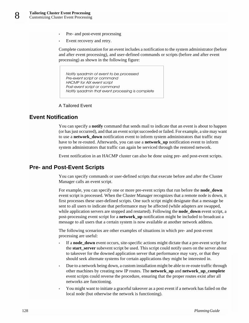
Tailoring Cluster Event ProcessingCustomizing Cluster Event Processing
12
8
• Pre- and post-event processing• Event recovery and retry.
Complete customization for an event includes a notification to the system administrator (before and after event processing), and user-defined commands or scripts (before and after event processing) as shown in the following figure:
A Tailored Event
Event NotificationYou can specify a notify command that sends mail to indicate that an event is about to happen (or has just occurred), and that an event script succeeded or failed. For example, a site may want to use a network_down notification event to inform system administrators that traffic may have to be re-routed. Afterwards, you can use a network_up notification event to inform system administrators that traffic can again be serviced through the restored network.
Event notification in an HACMP cluster can also be done using pre- and post-event scripts.
Pre- and Post-Event Scripts You can specify commands or user-defined scripts that execute before and after the Cluster Manager calls an event script.
For example, you can specify one or more pre-event scripts that run before the node_down event script is processed. When the Cluster Manager recognizes that a remote node is down, it first processes these user-defined scripts. One such script might designate that a message be sent to all users to indicate that performance may be affected (while adapters are swapped, while application servers are stopped and restarted). Following the node_down event script, a post-processing event script for a network_up notification might be included to broadcast a message to all users that a certain system is now available at another network address.
The following scenarios are other examples of situations in which pre- and post-event processing are useful:• If a node_down event occurs, site-specific actions might dictate that a pre-event script for
the start_server subevent script be used. This script could notify users on the server about to takeover for the downed application server that performance may vary, or that they should seek alternate systems for certain applications they might be interested in.
• Due to a network being down, a custom installation might be able to re-route traffic through other machines by creating new IP routes. The network_up and network_up_complete event scripts could reverse the procedure, ensuring that the proper routes exist after all networks are functioning.
• You might want to initiate a graceful takeover as a post event if a network has failed on the local node (but otherwise the network is functioning).
8 Planning Guide

Tailoring Cluster Event ProcessingCustomizing Event Duration Time Until Warning 8
If you plan to create pre- or post-event scripts for your cluster, be aware that your scripts will be passed the same parameters used by the HACMP event script you specify. The first parameter passed will be the event name; other parameters passed are those used by the HACMP event. For example, for the network_down event, the following parameters are passed to your script: the event name, network_down, followed by the name of the node and network experiencing the failure.
Note: When writing your pre- or post-event, all shell environment variables defined in /etc/environment will be available to your program. HACMP may alter some of these variables, for example PATH, to ensure the correct operation of the event scripts.
All HACMP event scripts are maintained in the /usr/sbin/cluster/events directory. The parameters passed to each script are listed in the event script headers.
See the Installation Guide for more tips on adding pre- and post-event scripts.
Event Recovery and RetryYou can specify a command that attempts to recover from an event script failure. If the recovery command succeeds and the retry count for the event script is greater than zero, the event script is rerun. You can also specify the number of times to attempt to execute the recovery command.
For example, a recovery command could include the retry of unmounting a filesystem after logging a user off, and making sure no one was currently accessing the filesystem.
If a condition that affects the processing of a given event on a cluster is identified, such as a timing issue, you can insert a recovery command with a retry count high enough to be sure to cover for the problem.
Customizing Event Duration Time Until WarningHACMP software issues a system warning each time a cluster event takes more time to complete than a specified time-out period. In versions prior to 4.5, the time-out period was fixed for all cluster events and set to 360 seconds by default. If a cluster event, such as a node_up or a node_down event, lasts longer than 360 seconds, then every 30 seconds HACMP issues a config_too_long warning message that is logged in the hacmp.out file.
In HACMP 4.5, you can customize the time period allowed for a cluster event to complete before HACMP issues a system warning for it. You customize this time using the SMIT interface.
Planning Event Duration Time Before WarningDepending on cluster configuration, the speed of cluster nodes and the number and types of resources that need to move during cluster events, certain events may take different times to complete. For such events, you may want to customize the time period HACMP waits for an event to complete before issuing the config_too_long warning message.
Cluster events that include acquiring and releasing resource groups take a longer time to complete. They are considered “slow” events and include the following:
Planning Guide 129

Tailoring Cluster Event ProcessingCustom Pager Notification
13
8
• node_up• node_down• resource_reconfig
Customizing event duration time for “slow” cluster events lets you avoid getting unnecessary system warnings during normal cluster operation.
All other cluster events are considered “fast” events. They normally take a shorter time to complete and do not involve acquiring or releasing resources. Examples of “fast” events include:• adapter_swap• events that do not handle resource groups.
Customizing event duration time before receiving a warning for “fast” events allows you to take corrective action faster.
Consider customizing event duration time before receiving a warning if, in the case of “slow” cluster events, HACMP issues warning messages too frequently; or, in the case of “fast” events, you want to speed up detection of a possible problem event.
Remember, you can customize event duration time before receiving a warning for cluster events, not for nodes or specific resource groups in your cluster. Once the Total Event Duration Time is specified, the system waits for the specified period of time and sends a config_too_long message to the node which was affected by this event.
For information on how to customize event duration time before receiving a warning, see the chapter on customizing cluster events in the Installation Guide.
Custom Pager NotificationYou can define a notification method through the SMIT interface to issue a customized page in response to a cluster event.
You can configure any number of notification methods, for different events and with different text messages and telephone numbers to dial. The same notification method can be used for several different events, as long as the associated text message conveys enough information to respond to all of the possible events that trigger the page.
Planning for Custom Pager NotificationThe pager notification functionality requires the following conditions:• A tty port used for paging cannot also be used for heartbeat traffic.• Any tty port specified must be defined to AIX and must be available.• Each node that may send a page must have an appropriate Hayes-compatible modem
installed and enabled.
Note: HACMP checks the availability of the tty port when the notification method is configured, and before a page is issued, but modem status is not checked.
0 Planning Guide

Tailoring Cluster Event ProcessingCompleting the Cluster Event Worksheet 8
Instructions for configuring a pager notification method are included in the chapter on customizing cluster events in the Installation Guide.
Completing the Cluster Event WorksheetYou now fill out a worksheet that helps you plan the cluster event processing for your cluster. Appendix A: Planning Worksheets, has blank copies of the worksheet referenced in the procedure. Make photocopies of this worksheet to record all your cluster event scripts.
For instructions on entering cluster event data in the online worksheets, see Appendix B: Using the Online Planning Worksheet Program.
Complete the following steps to plan the customized processing for a specific cluster event. Enter values in the fields only as necessary.
1. Record the cluster ID in the Cluster ID field.
2. Record the cluster name in the Cluster Name field.
3. Record the cluster event description in the Cluster Event Description field.
4. Record the full pathname of the cluster event method in the Cluster Event Method field.
5. Fill in the name of the cluster event in the Cluster Event Name field.
6. Fill in the name of the event script in the Event Command field.
7. Record the full pathname of the event notification script in the Notify Command field.
8. Record the name of the pre-event script in the Pre-Event Command field.
9. Record the name of the post-event script in the Post-Event Command field.
10. Record the full pathname of the event retry script in the Event Recovery Command field.
11. Indicate the number of times to retry in the Recovery Counter field.
Repeat steps 3 through 11 for each event you plan to customize.
Where You Go From HereYou have now planned the customized event processing for your cluster. Next, you address issues relating to cluster clients, as described in Chapter 9: Planning HACMP Clients.
Planning Guide 131

Tailoring Cluster Event ProcessingWhere You Go From Here
13
8
2 Planning Guide

Planning HACMP ClientsPrerequisites 9
Chapter 9: Planning HACMP ClientsThis chapter discusses planning considerations for HACMP clients.
PrerequisitesComplete the planning steps in the previous chapters before reading this chapter.
OverviewClients are end-user devices that can access the nodes in an HACMP cluster. In this stage of the planning process, you evaluate the cluster from the point of view of the clients. You need to consider the following:• Different types of clients (computers and terminal servers)• Clients with and without the Client Information Program (Clinfo)• Network components (routers, bridges, gateways).
Different Types of Clients: Computers and Terminal Servers
Clients may include a variety of hardware and software from different vendors. In order to maintain connectivity with the HACMP cluster, you must consider the following issues.
Client Application SystemsAll clients should run Clinfo if possible. If you have hardware other than RS/6000 nodes in the configuration, you may want to port Clinfo to those platforms. Clinfo source code is provided as part of the HACMP release.
You need to think about what applications are running on these clients. Who are the users? Is it required or appropriate for users to receive a message when cluster events affect their system?
NFS ServersIssues related to NFS are discussed in Chapter 6: Planning Shared LVM Components.
Terminal ServersIf you plan to use a terminal server on the local area network, consider the following when choosing the hardware:• Can you update the terminal server’s ARP cache? The terminal server must comply with
the TCP/IP protocol, including telnet.
Planning Guide 133

Planning HACMP ClientsClients Running Clinfo
13
9
• Is the terminal server programmable, or does it need manual intervention when a cluster event happens?
• Can you download a control file from the cluster node to the terminal server that updates or handles cluster events’ effects on clients?
If your terminal server does not meet these operating requirements, you should choose the hardware address swapping option when configuring the cluster environment.
Clients Running ClinfoThe Clinfo program calls the /usr/sbin/cluster/etc/clinfo.rc script whenever a network or node event occurs. By default, this action updates the system’s ARP cache to reflect changes to network addresses. You can customize this script if further action is desired.
Reconnecting to the ClusterClients running the Clinfo daemon will be able to reconnect to the cluster quickly after a cluster event. If you have hardware other than RS/6000s, SPs, or SMPs between the cluster and the clients, you must make sure that you can update the ARP cache of those network components after a cluster event occurs.
If you configure the cluster to swap hardware addresses as well as IP addresses, you do not need to be concerned about updating the ARP cache. You simply must be aware that this option causes a longer delay for the users.
Tailoring the clinfo.rc ScriptFor clients running Clinfo, you need to decide whether to tailor the /usr/sbin/cluster/etc/clinfo.rc script to do more than update the ARP cache when a cluster event occurs. See the Installation Guide for more information. Also see the Programming Client Applications Guide for a sample tailored clinfo.rc script.
Network Components and Clients Not Running ClinfoIf you have configured the network so that clients attach to networks on the other side of a router, bridge, or gateway rather than to the cluster’s local networks, you must be sure that you can update the ARP cache of those network components after a cluster event occurs. If this is not possible, be sure to use hardware address swapping when you configure the cluster environment. If hardware address swapping is not enabled, you will also need to update the ARP cache of non-Clinfo clients on the same subnet and physical network segment in a similar manner. Keep in mind that Clinfo can monitor a maximum of eight clusters.
See the Installation Guide for more information about updating non-Clinfo clients.
4 Planning Guide

Planning HACMP ClientsWhere You Go From Here 9
Where You Go From HereThis chapter concludes the planning process. You can now begin to install the HACMP software. See the Installation Guide for detailed instructions on installing the HACMP software.
Planning Guide 135

Planning HACMP ClientsWhere You Go From Here
13
9
6 Planning Guide

Planning Worksheets A
Appendix A: Planning WorksheetsNote: You should print and use the paper planning worksheets from the PDF
version of this guide rather than the HTML version. In the PDF version, each new worksheet is aligned properly to start at the top of a page.
This appendix contains the following worksheets:
Worksheet Purpose
TCP/IP Networks Use this worksheet to record the TCP/IP network topology for a cluster. Complete one worksheet per cluster.
TCP/IP Network Adapter Use this worksheet to record the TCP/IP network adapters connected to each node. You need a separate worksheet for each node defined in the cluster, so begin by photocopying a worksheet for each node and filling in a node name on each worksheet.
Serial Networks Use this worksheet to record the serial network topology for a cluster. Complete one worksheet per cluster.
Serial Network Adapter Use this worksheet to record the serial network adapters connected to each node. You need a separate worksheet for each node defined in the cluster, so begin by photocopying a worksheet for each node and filling in the node name on each worksheet.
Shared SCSI-2 Differential or Differential Fast/Wide Disks
Use this worksheet to record the shared SCSI-2 Differential or Differential Fast/Wide disk configuration for the cluster. Complete a separate worksheet for each shared bus.
Shared IBM SCSI Disk Arrays
Use this worksheet to record the shared IBM SCSI disk array configurations for the cluster. Complete a separate worksheet for each shared SCSI bus.
Shared IBM SCSI Tape Drives
Use this worksheet to record the shared IBM SCSI tape drive configurations for the cluster. Complete a separate worksheet for each shared tape drive.
Shared IBM Fibre Tape Drives
Use this worksheet to record the shared IBM Fibre tape drive configurations for the cluster. Complete a separate worksheet for each shared tape drive.
Shared IBM Serial Storage Architecture Disk Subsystem
Use this worksheet to record the IBM 7131-405 or 7133 SSA shared disk configuration for the cluster.
Non-Shared Volume Group (Non-Concurrent Access)
Use this worksheet to record the volume groups and filesystems that reside on a node’s internal disks in a non-concurrent access configuration. You need a separate worksheet for each volume group, so begin by photocopying a worksheet for each volume group and filling in a node name on each worksheet.
Planning Guide 137

Planning Worksheets
13
A
Shared Volume Group/Filesystem (Non-Concurrent Access)
Use this worksheet to record the shared volume groups and filesystems in a non-concurrent access configuration. You need a separate worksheet for each shared volume group, so begin by photocopying a worksheet for each volume group and filling in the names of the nodes sharing the volume group on each worksheet.
NFS-Exported Filesystem/Directory
Use this worksheet to record the filesystems and directories NFS-exported by a node in a non-concurrent access configuration. You need a separate worksheet for each node defined in the cluster, so begin by photocopying a worksheet for each node and filling in a node name on each worksheet.
Non-Shared Volume Group (Concurrent Access)
Use this worksheet to record the volume groups and filesystems that reside on a node’s internal disks in a concurrent access configuration. You need a separate worksheet for each volume group, so begin by photocopying a worksheet for each volume group and filling in a node name on each worksheet.
Shared Volume Group (Concurrent Access)
Use this worksheet to record the shared volume groups and filesystems in a concurrent access configuration. You need a separate worksheet for each shared volume group, so begin by photocopying a worksheet for each volume group and filling in the names of the nodes sharing the volume group on each worksheet.
Application Use these worksheets to record information about applications in the cluster.
AIX Fast Connect Use this worksheet to record the Fast Connect resources you plan to configure in resource groups
AIX Connections Use this worksheet to record realm/service pairs for AIX Connections
Application Server Use these worksheets to record information about application servers in the cluster.
Communication Links (SNA-Over-LAN)
Use this worksheets to record information about SNA-over-LAN communications links in the cluster.
Communication Links (X.25)
Use this worksheets to record information about X.25 communications links in the cluster.
Communication Links (SNA-Over-X.25)
Use this worksheets to record information about SNA-over-X.25 communications links in the cluster.
Resource Group Use this worksheet to record the resource groups for a cluster.
Cluster Event Use this worksheet to record the planned customization for an HACMP cluster event.
Worksheet Purpose
8 Planning Guide

Planning WorksheetsTCP/IP Networks Worksheet A
TCP/IP Networks WorksheetCluster ID____________
Cluster Name____________
Network Name Network Type Network Attribute Netmask Node Names
________________ ________________ ________________ ________________ ________________
________________ ________________ ________________ ________________ ________________
________________ ________________ ________________ ________________ ________________
________________ ________________ ________________ ________________ ________________
________________ ________________ ________________ ________________ ________________
________________ ________________ ________________ ________________ ________________
________________ ________________ ________________ ________________ ________________
________________ ________________ ________________ ________________ ________________
________________ ________________ ________________ ________________ ________________
Planning Guide 139
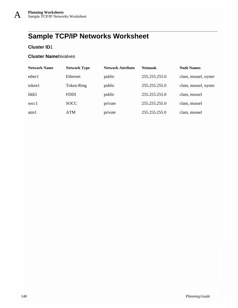
Planning WorksheetsSample TCP/IP Networks Worksheet
14
A
Sample TCP/IP Networks WorksheetCluster ID1
Cluster Namebivalves
Network Name Network Type Network Attribute Netmask Node Names
ether1 Ethernet public 255.255.255.0 clam, mussel, oyster
token1 Token-Ring public 255.255.255.0 clam, mussel, oyster
fddi1 FDDI public 255.255.255.0 clam, mussel
socc1 SOCC private 255.255.255.0 clam, mussel
atm1 ATM private 255.255.255.0 clam, mussel
0 Planning Guide

Planning WorksheetsTCP/IP Network Adapter Worksheet A
TCP/IP Network Adapter WorksheetNode Name__________
Note: The SMIT Add an Adapter screen displays an Adapter Identifier field that correlates with the Adapter IP Address field on this worksheet.
Also, entries in the Adapter HW Address field should refer to the locally administered address (LAA), which applies only to the service adapter.
Interface Name
Adapter IP Label
Adapter Function
Adapter IP Address
Network Name
Network Attribute
Boot Address Adapter HW Address
________________________________________________________________________________________
________________________________________________________________________________________
________________________________________________________________________________________
________________________________________________________________________________________
________________________________________________________________________________________
________________________________________________________________________________________
________________________________________________________________________________________
________________________________________________________________________________________
________________________________________________________________________________________
Planning Guide 141

Planning WorksheetsSample TCP/IP Network Adapter Worksheet
142
A
Sample TCP/IP Network Adapter WorksheetNode Name nodea
Note: The SMIT Add an Adapter screen displays an Adapter Identifier field that correlates with the Adapter IP Address field on this worksheet.
Also, entries in the Adapter HW Address field should refer to the locally administered address (LAA), which applies only to the service adapter.
Interface Name
Adapter IP Label
Adapter Function
Adapter IP Address
Network Name
Network Attribute
Boot Address Adapter HW Address
len0 nodea-en0 service 100.10.1.10 ether1 public 0x08005a7a7610
en0 nodea-boot1 boot 100.10.1.74 ether1 public
en1 nodea-en1 standby 100.10.11.11 ether1 public
tr0 nodea-tr0 service 100.10.2.20 token1 public 0x42005aa8b57b
tr0 nodea-boot2 boot 100.10.2.84 token1 public
fi0 nodea-fi0 service 100.10.3.30 fddi1 public
sl0 nodea-sl0 service 100.10.5.50 slip1 public
css0 nodea-svc service hps1 private
css0 nodea-boot3 boot hps1 private
at0 nodea-at0 service 100.10.7.10 atm1 private 0x0020481a396500
at0 nodea-boot1 boot 100.10.7.74 atm1 private
Planning Guide

Planning WorksheetsSerial Networks Worksheet A
Serial Networks WorksheetCluster ID____________
Cluster Name____________
Note: RS232 serial lines, target mode SCSI-2 buses, and tmssa serial links do not use the TCP/IP protocol and do not require a netmask or an IP address.
Miscellaneous Data Record any extra information about devices used to extend serial links, for instance modem number or extender information.
_________________________________________________________________________
_________________________________________________________________________
_________________________________________________________________________
_________________________________________________________________________
Network Name Network Type Network Attribute Node Names
________________ ________________ serial ________________
________________ ________________ serial ________________
________________ ________________ serial ________________
________________ ________________ serial ________________
________________ ________________ serial ________________
________________ ________________ serial ________________
________________ ________________ serial ________________
________________ ________________ serial ________________
________________ ________________ serial ________________
Planning Guide 143

Planning WorksheetsSample Serial Networks Worksheet
14
A
Sample Serial Networks WorksheetCluster ID1
Cluster Nameclus1
Note: RS232 serial lines, target mode SCSI-2 buses, and tmssa serial links do not use the TCP/IP protocol and do not require a netmask or an IP address.
Miscellaneous Data Record any extra information about devices used to extend serial links, for instance modem number or extender information.
_________________________________________________________________________
_________________________________________________________________________
_________________________________________________________________________
_________________________________________________________________________
Network Name Network Type Network Attribute Node Names
rs232a RS232 serial nodea, nodeb
tmscsi1 Target Mode SCSI serial nodea, nodeb
4 Planning Guide
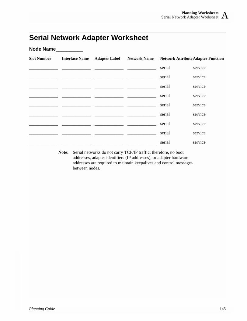
Planning WorksheetsSerial Network Adapter Worksheet A
Serial Network Adapter WorksheetNode Name__________
Note: Serial networks do not carry TCP/IP traffic; therefore, no boot addresses, adapter identifiers (IP addresses), or adapter hardware addresses are required to maintain keepalives and control messages between nodes.
Slot Number Interface Name Adapter Label Network Name Network Attribute Adapter Function
_____________ _____________ _____________ _____________ serial service
_____________ _____________ _____________ _____________ serial service
_____________ _____________ _____________ _____________ serial service
_____________ _____________ _____________ _____________ serial service
_____________ _____________ _____________ _____________ serial service
_____________ _____________ _____________ _____________ serial service
_____________ _____________ _____________ _____________ serial service
_____________ _____________ _____________ _____________ serial service
_____________ _____________ _____________ _____________ serial service
Planning Guide 145

Planning WorksheetsSample Serial Network Adapter Worksheet
14
A
Sample Serial Network Adapter WorksheetNode Name nodea
Note: Serial networks do not carry TCP/IP traffic; therefore, no boot addresses, adapter identifiers (IP addresses), or adapter hardware addresses are required to maintain keepalives and control messages between nodes.
Slot Number Interface Name Adapter Label Network Name Network Attribute Adapter Function
SS2 /dev/tty1 nodea-tty1 rs232a serial service
08 scsi2 nodea-tmscsi2 tmscsi1 serial service
6 Planning Guide

Planning WorksheetsShared SCSI-2 Differential or Differential Fast/Wide Disks Worksheet A
Shared SCSI-2 Differential or Differential Fast/Wide Disks Worksheet
Note: Complete a separate worksheet for each shared SCSI-2 Differential bus or Differential Fast/Wide bus. Keep in mind that the IBM SCSI-2 Differential High Performance Fast/Wide adapter cannot be assigned SCSI IDs 0, 1, or 2. The SCSI-2 Differential Fast/Wide adapter cannot be assigned SCSI IDs 0 or 1.
Type of SCSI-2 Bus
Host and Adapter Information
SCSI Device IDs on Shared Bus
Shared Drives
SCSI-2 Differential ____________________ SCSI-2 Differential Fast/Wide ____________________
Node A Node B Node C Node D
Node Name ______________ ______________ ______________ ______________
Slot Number ______________ ______________ ______________ ______________
Logical Name ______________ ______________ ______________ ______________
Node A Node B Node C Node D
Adapter ______________ ______________ ______________ ______________
First Shared Drive ______________
Second Shared Drive ______________
Third Shared Drive ______________
Fourth Shared Drive ______________
Fifth Shared Drive ______________
Sixth Shared Drive ______________
Disk Size Logical Device Name
Node A Node B Node C Node D
First _____________ _____________ _____________ _____________ _____________
Second _____________ _____________ _____________ _____________ _____________
Third _____________ _____________ _____________ _____________ _____________
Fourth _____________ _____________ _____________ _____________ _____________
Fifth _____________ _____________ _____________ _____________ _____________
Sixth _____________ _____________ _____________ _____________ _____________
Planning Guide 147

Planning WorksheetsSample Shared SCSI-2 Differential or Differential Fast/Wide Disks Worksheet
14
A
Sample Shared SCSI-2 Differential or Differential Fast/Wide Disks Worksheet
Note: Complete a separate worksheet for each shared SCSI-2 Differential bus or Differential Fast/Wide bus. Keep in mind that the IBM SCSI-2 Differential High Performance Fast/Wide adapter cannot be assigned SCSI IDs 0, 1, or 2. The SCSI-2 Differential Fast/Wide adapter cannot be assigned SCSI IDs 0 or 1.
Type of SCSI-2 Bus
Host and Adapter Information
SCSI Device IDs on Shared Bus
Shared Drives
SCSI-2 Differential SCSI-2 Differential Fast/Wide X
Node A Node B Node C Node D
Node Name nodea nodeb
Slot Number 7 7
Logical Name ascsi1 ascsi1
Node A Node B Node C Node D
Adapter 6 5
First Shared Drive 3
Second Shared Drive 4
Third Shared Drive 5
Fourth Shared Drive
Fifth Shared Drive
Sixth Shared Drive
Disk Size Logical Device Name
Node A Node B Node C Node D
First 670 hdisk2 hdisk2
Second 670 hdisk3 hdisk3
Third 670 hdisk4 hdisk4
Fourth
Fifth
Sixth
8 Planning Guide

Planning WorksheetsShared IBM SCSI Disk Arrays Worksheet A
Shared IBM SCSI Disk Arrays WorksheetNote: Complete a separate worksheet for each shared SCSI disk array.
Host and Adapter Information
SCSI Device IDs on Shared Bus
Array Controller and Path Information
Node A Node B Node C Node D
Node Name ______________ ______________ ______________ ______________
Slot Number ______________ ______________ ______________ ______________
Logical Name ______________ ______________ ______________ ______________
Node A Node B Node C Node D
Adapter ______________ ______________ ______________ ______________
First Array Controller ______________ ______________ ______________ ______________
Second Array Controller ______________ ______________ ______________ ______________
Third Array Controller ______________ ______________ ______________ ______________
Fourth Array Controller ______________ ______________ ______________ ______________
Shared Drives Shared LUNs
Size RAID Level Logical Device Name
Node A Node B Node C Node D
______________ ______________ ______________ ______________ ______________ ______________
______________ ______________ ______________ ______________ ______________ ______________
______________ ______________ ______________ ______________ ______________ ______________
______________ ______________ ______________ ______________ ______________ ______________
______________ ______________ ______________ ______________ ______________ ______________
Array 1 Array 2
Array Controller Logical Name ______________ ______________
Array Controller Logical Name ______________ ______________
Disk Array Router Logical Name ______________ ______________
Planning Guide 149

Planning WorksheetsSample Shared IBM SCSI Disk Arrays Worksheet
15
A
Sample Shared IBM SCSI Disk Arrays WorksheetThis sample worksheet shows an IBM 7135 RAIDiant Disk Array configuration.
Note: Complete a separate worksheet for each shared SCSI disk array.
Host and Adapter Information
SCSI Device IDs on Shared Bus
Array Controller and Path Information
Node A Node B Node C Node D
Node Name nodea nodeb
Slot Number 2 2
Logical Name ascsi1 ascsi1
Node A Node B Node C Node D
Adapter 14 15
First Array Controller 3
Second Array Controller 4
Third Array Controller
Fourth Array Controller
Shared Drives Shared LUNs
Size RAID Level Logical Device Name
Node A Node B Node C Node D
2GB 5 hdisk2 hdisk2
2GB 3 hdisk3 hdisk3
2GB 5 hdisk4 hdisk4
2GB 5 hdisk5 hdisk5
RAIDiant 1
Array Controller Logical Name dac0
Array Controller Logical Name dac1
Disk Array Router Logical Name dar0
0 Planning Guide

Planning WorksheetsShared IBM SCSI Tape Drive Worksheet A
Shared IBM SCSI Tape Drive WorksheetNote: Complete a separate worksheet for each shared SCSI tape drive.
Host and Adapter Information
SCSI Tape Drive IDs on Shared Bus
Node A Node B
Node Name ______________ ______________
Slot Number ______________ ______________
Logical Name ______________ ______________
Node A Node B
Adapter ______________ ______________
Tape Drive ______________ ______________
Shared Drives Logical Device Name
Node A Node B
______________ ______________ ______________
______________ ______________ ______________
______________ ______________ ______________
______________ ______________ ______________
Planning Guide 151

Planning WorksheetsSample Shared IBM SCSI Tape Drive Worksheet
15
A
Sample Shared IBM SCSI Tape Drive WorksheetThis sample worksheet shows a shared SCSI tape drive configuration.
Note: Complete a separate worksheet for each tape drive.
Host and Adapter Information
SCSI Device IDs on Shared Bus
Node A Node B
Node Name nodea nodeb
Slot Number 2 2
Logical Name ascsi1 ascsi1
Node A Node B
Adapter 5 6
Tape Drive 2
Shared Drives Logical Device Name
Node A Node B
5.0GB 8mm tape drive /dev/rmt0 /dev/rmt0
2 Planning Guide

Planning WorksheetsShared IBM Fibre Tape Drive Worksheet A
Shared IBM Fibre Tape Drive WorksheetNote: Little configuration planning is necessary for Fibre Tape drives. If
planning to use many tape drives, you probably should record the Host and Adapter information. You can use the worksheet to record the rest of the configuration information after it is done.
Host and Adapter Information
Fibre Device IDs on Shared Bus
Node A Node B
Node Name ______________ ______________
Slot Number ______________ ______________
Logical Name ______________ ______________
Node A Node B
SCSI ID ______________ ______________
LUN ID
World Wide Name
Shared Drives Logical Device Name
Tape Drive Name Node A Node B
______________ ______________ ______________
______________ ______________ ______________
______________ ______________ ______________
______________ ______________ ______________
Planning Guide 153

Planning WorksheetsSample Shared IBM Fibre Tape Drive Worksheet
15
A
Sample Shared IBM Fibre Tape Drive WorksheetThis sample worksheet shows a shared Fibre tape drive configuration (recorded after the tape drive had been configured).
Note: Complete a separate worksheet for each tape drive.
Host and Adapter Information
Fibre Device IDs on Shared Bus
Node A Node B
Node Name nodea nodeb
Slot Number 1P-18 04-02
Logical Name fcs0 fcs0
Node A Node B
SCSI IDLUN IDWorld Wide Name
scsi_id 0x26lun_id 0x0ww_name 0x5005076300404576
scsi_id 0x26lun_id 0x0ww_name 0x5005076300404576
Shared Drives Logical Device Name
Tape Drive Name Node A Node B
IBM 3590 /dev/rmt0 /dev/rmt0
4 Planning Guide

Planning WorksheetsShared IBM Serial Storage Architecture Disk Subsystems Worksheet A
Shared IBM Serial Storage Architecture Disk Subsystems WorksheetHost and Adapter Information
SSA Logical Disk Drive
SSA Logical Disk Drive
Node A Node B Node C Node D
Node Name _____________ _____________ _____________ _____________
SSA Adapter Label _____________ _____________ _____________ _____________
Slot Number _____________ _____________ _____________ _____________
Dual-Port Number _____________ _____________ _____________ _____________
Logical Device Name
Node A Node B Node C Node D
_______________ _______________ _______________ _______________
_______________ _______________ _______________ _______________
_______________ _______________ _______________ _______________
_______________ _______________ _______________ _______________
Planning Guide 155

Planning WorksheetsSample Shared IBM Serial Storage Architecture Disk Subsystems Worksheet
15
A
Sample Shared IBM Serial Storage Architecture Disk Subsystems WorksheetHost and Adapter Information
SSA Logical Disk Drive
SSA Logical Disk Drive
Node A Node B Node C Node D
Node Name clam mussel
SSA Adapter Label ha1, ha2 ha1, ha2
Slot Number 2, 4 2, 4
Dual-Port Number a1, a2 a1, a2
Logical Device Name
Node A Node B Node C Node D
hdisk2 hdisk2
hdisk3 hdisk3
hdisk4 hdisk4
hdisk5 hdisk5
Logical Device Name
Node A Node B Node C Node D
hdisk2 hdisk2
hdisk3 hdisk3
hdisk4 hdisk4
hdisk5 hdisk5
6 Planning Guide

Planning WorksheetsNon-Shared Volume Group Worksheet (Non-Concurrent Access) A
Non-Shared Volume Group Worksheet (Non-Concurrent Access)Node Name________________
Volume Group Name________________
Physical Volumes________________
________________
________________
Logical Volume Name________________
Number of Copies of Logical Partition________________
On Separate Physical Volumes?________________
Filesystem Mount Point________________
Size (in 512-byte blocks)________________
Logical Volume Name________________
Number of Copies of Logical Partition________________
On Separate Physical Volumes?________________
Filesystem Mount Point________________
Size (in 512-byte blocks)________________
Planning Guide 157

Planning WorksheetsSample Non-Shared Volume Group Worksheet (Non-Concurrent Access)
15
A
Sample Non-Shared Volume Group Worksheet (Non-Concurrent Access)Node Nameclam
Volume Group Namelocalvg
Physical Volumeshdisk1
________________
________________
Logical Volume Namelocallv
Number of Copies of Logical Partition1
On Separate Physical Volumes?no
Filesystem Mount Point/localfs
Size (in 512-byte blocks)100000
Logical Volume Name________________
Number of Copies of Logical Partition________________
On Separate Physical Volumes?________________
Filesystem Mount Point________________
Size (in 512-byte blocks)________________
8 Planning Guide

Planning WorksheetsShared Volume Group/Filesystem Worksheet (Non-Concurrent Access) A
Shared Volume Group/Filesystem Worksheet (Non-Concurrent Access)
Logical Volume Name________________
Number of Copies of Logical Partition________________
On Separate Physical Volumes?________________
Filesystem Mount Point________________
Size (in 512-byte blocks)________________
Logical Volume Name________________
Number of Copies of Logical Partition________________
On Separate Physical Volumes?________________
Filesystem Mount Point________________
Size (in 512-byte blocks)________________
Node A Node B Node C Node D
Node Names _______________ _______________ _______________ _______________
Shared Volume Group Name _______________
Major Number _______________ _______________ _______________ _______________
Log Logical Volume Name _______________
Physical Volumes _______________ _______________ _______________ _______________
_______________ _______________ _______________ _______________
_______________ _______________ _______________ _______________
Planning Guide 159

Planning WorksheetsSample Shared Volume Group/Filesystem Worksheet (Non-Concurrent Access)
16
A
Sample Shared Volume Group/Filesystem Worksheet (Non-Concurrent Access)
Logical Volume Namebasslv
Number of Copies of Logical Partition3
On Separate Physical Volumes?yes
Filesystem Mount Point/bassfs
Size (in 512-byte blocks)200000
Logical Volume Name________________
Number of Copies of Logical Partition________________
On Separate Physical Volumes?________________
Filesystem Mount Point________________
Size (in 512-byte blocks)________________
Node A Node B Node C Node D
Node Names trout guppy
Shared Volume Group Name bassvg
Major Number 24 24
Log Logical Volume Name bassloglv
Physical Volumes hdisk6 hdisk6
hdisk7 hdisk7
hdisk13 hdisk16
0 Planning Guide

Planning WorksheetsNFS-Exported Filesystem or Directory Worksheet (Non-Concurrent Access) A
NFS-Exported Filesystem or Directory Worksheet (Non-Concurrent Access)Resource Group__________
Network for NFS Mount__________
Filesystem Mounted Before IP Configured?__________
Filesystem/Directory to Export__________
Export Options (read-only, etc.) Refer to the exports man page for a full list of export options:
Filesystem/Directory to Export__________
Export Options (read-only, etc.) Refer to the exports man page for a full list of export options:
Filesystem/Directory to Export__________
Export Options (read-only, etc.) Refer to the exports man page for a full list of export options:
_________________________ _________________________ _________________________
_________________________ _________________________ _________________________
_________________________ _________________________ _________________________
_________________________ _________________________ _________________________
_________________________ _________________________ _________________________
_________________________ _________________________ _________________________
_________________________ _________________________ _________________________
_________________________ _________________________ _________________________
_________________________ _________________________ _________________________
Planning Guide 161

Planning WorksheetsSample NFS-Exported Filesystem or Directory Worksheet (Non-Concurrent Access)
16
A
Sample NFS-Exported Filesystem or Directory Worksheet (Non-Concurrent Access)Resource Grouprg1
Network for NFS Mounttr1
Filesystem Mounted Before IP Configured?true
Filesystem/Directory to Export/fs1
Export Options (read-only, root access, etc.) Refer to the exports man page for a full list of export options:
Filesystem/Directory to Export/fs 2
Export Options (read-only, root access, etc.) Refer to the exports man page for a full list of export options:
client access:client1 _________________________ _________________________
root access: node 1, node 2 _________________________ _________________________
mode: read/write _________________________ _________________________
client access:client 2 _________________________ _________________________
root access: node 3, node 4 _________________________ _________________________
mode: read only _________________________ _________________________
2 Planning Guide

Planning WorksheetsNon-Shared Volume Group Worksheet (Concurrent Access) A
Non-Shared Volume Group Worksheet (Concurrent Access)Node Name________________
Volume Group Name________________
Physical Volumes________________
________________
________________
Logical Volume Name________________
Number of Copies of Logical Partition________________
On Separate Physical Volumes?________________
Filesystem Mount Point________________
Size (in 512-byte blocks)________________
Logical Volume Name________________
Number of Copies of Logical Partition________________
On Separate Physical Volumes?________________
Filesystem Mount Point________________
Size (in 512-byte blocks)________________
Planning Guide 163

Planning WorksheetsSample Non-Shared Volume Group Worksheet (Concurrent Access)
16
A
Sample Non-Shared Volume Group Worksheet (Concurrent Access)Node Nameclam
Volume Group Namelocalvg
Physical Volumeshdisk1
________________
________________
Logical Volume Namelocallv
Number of Copies of Logical Partition1
On Separate Physical Volumes?no
Filesystem Mount Point/localfs
Size (in 512-byte blocks)100000
Logical Volume Name________________
Number of Copies of Logical Partition________________
On Separate Physical Volumes?________________
Filesystem Mount Point________________
Size (in 512-byte blocks)________________
4 Planning Guide

Planning WorksheetsShared Volume Group/Filesystem Worksheet (Concurrent Access) A
Shared Volume Group/Filesystem Worksheet (Concurrent Access)
Logical Volume Name________________
Number of Copies of Logical Partition________________
On Separate Physical Volumes?________________
Logical Volume Name________________
Number of Copies of Logical Partition________________
On Separate Physical Volumes?________________
Logical Volume Name________________
Number of Copies of Logical Partition________________
On Separate Physical Volumes?________________
Logical Volume Name________________
Number of Copies of Logical Partition________________
On Separate Physical Volumes?________________
Node A Node B Node C Node D
Node Names _______________ _______________ _______________ _______________
Shared Volume Group Name _______________
Physical Volumes _______________ _______________ _______________ _______________
_______________ _______________ _______________ _______________
_______________ _______________ _______________ _______________
Planning Guide 165

Planning WorksheetsSample Shared Volume Group/Filesystem Worksheet (Concurrent Access)
16
A
Sample Shared Volume Group/Filesystem Worksheet (Concurrent Access)
Logical Volume Namebasslv
Number of Copies of Logical Partition3
On Separate Physical Volumes?yes
Filesystem Mount Point/bassfs
Size (in 512-byte blocks)200000
Logical Volume Name________________
Number of Copies of Logical Partition________________
On Separate Physical Volumes?________________
Filesystem Mount Point________________
Size (in 512-byte blocks)________________
Logical Volume Name________________
Number of Copies of Logical Partition________________
On Separate Physical Volumes?________________
Node A Node B Node C Node D
Node Names trout guppy
Shared Volume Group Name bassvg
Physical Volumes hdisk6 hdisk6
hdisk7 hdisk7
hdisk13 hdisk16
6 Planning Guide

Planning WorksheetsApplication Worksheet A
Application WorksheetApplication Name_____________________
Normal Start Commands/Procedures:________________________________________________________________________________________________________________________________________________________________________________________________________________________________________________________________________________________________________________________
Verification Commands/Procedures:________________________________________________________________________________________________________________________________________________________________________________________________________________________________________________________________________________________________________________________
Node Reintegration/Takeover Caveats:
Key Application Files
Directory/Path Filesystem Location Sharing
Executables: _______________ _______________ _______________ ______________
Configuration Files: _______________ _______________ _______________ ______________
Data Files/Devices: _______________ _______________ _______________ ______________
Log Files/Devices: _______________ _______________ _______________ ______________
Cluster Name:
Node Relationship: (cascading/concurrent/rotating)
Fallover Strategy: (P = primary; T = takeover)
Node: _________ _________ _________ _________ _________ _________ _________ _________
Strategy: _________ _________ _________ _________ _________ _________ _________ _________
Node Reintegration/Takeover Caveats
____________ _______________________________________
____________ _______________________________________
____________ _______________________________________
____________ _______________________________________
Planning Guide 167

Planning WorksheetsApplication Worksheet
16
A
Normal Stop Commands/Procedures:________________________________________________________________________________________________________________________________________________________________________________________________________________________________________________________________________________________________________________________
Verification Commands/Procedures:________________________________________________________________________________________________________________________________________________________________________________________________________________________________________________________________________________________________________________________
Node Reintegration/Takeover Caveats:
____________ _______________________________________
____________ _______________________________________
____________ _______________________________________
____________ _______________________________________
____________ _______________________________________
Node Reintegration/Takeover Caveats
____________ _______________________________________
____________ _______________________________________
____________ _______________________________________
____________ _______________________________________
____________ _______________________________________
____________ _______________________________________
____________ _______________________________________
____________ _______________________________________
____________ _______________________________________
8 Planning Guide

Planning WorksheetsSample Application Worksheet A
Sample Application WorksheetApplication Name_____________________
Normal Start Commands/Procedures:• Verify that the app1 server group is running• If the app1 server group is not running, as user app1_adm, execute app1 start -I One• Verify that the app1 server is running• If node Two is up, start (restart) app1_client on node Two
Verification Commands/Procedures:• Run the following command: lssrc -g app1• Verify from the output that daemon1, daemon2, and daemon3 are “Active”• Send notification if not “Active”
Node Reintegration/Takeover Caveats:
Key Application Files
Directory/Path Filesystem Location Sharing
Executables: /app1/bin /app1 internal non-shared
Configuration Files: /app1/config/one /app1/config/one external shared
Data Files/Devices: /app1lv1 NA external shared
Log Files/Devices: /app1loglv1 NA external shared
Cluster Name: tetra
Node Relationship: (cascading/concurrent/rotating)
cascading
Fallover Strategy: (P = primary; T = takeover)
Node: One Two Three Four
Strategy: P NA T1 T2
Node Reintegration/Takeover Caveats
One NA
Two NA
Three Must restart the current instance of app1 with app1start -Ione -Ithree
Four Must restart the current instance of app1 with app1start -Ione -Ifour
Planning Guide 169

Planning WorksheetsSample Application Worksheet
17
A
Normal Stop Commands/Procedures:• Verify that the app1 server group is running• If the app1 server group is running, stop by app1stop as user app1_adm• Verify that the app1 server is stopped• If the app1 server is still up, stop individual daemons with the kill command
Verification Commands/Procedures:• Run the following command: lssrc -g app1• Verify from the output that daemon1, daemon2, and daemon3 are “Inoperative”
Node Reintegration/Takeover Caveats:
Note: In this sample worksheet, the server portion of the application, app1, normally runs on three of the four cluster nodes: nodes One, Three, and Four. Each of the three nodes is running its own app1 instance: one, three, or four. When a node takes over an app1 instance, the takeover node must restart the application server using flags for multiple instances. Also, because Node Two within this configuration runs the client portion associated with this instance of app1, the takeover node must restart the client when the client’s server instance is restarted.
Node Reintegration/Takeover Caveats
One NA
Two May want to notify app1_client users to log off
Three Must restart the current instance of app1 with app1start -Ithree
Four Must restart the current instance of app1 with app1start -Ifour
0 Planning Guide

Planning WorksheetsAIX Fast Connect Worksheet A
AIX Fast Connect Worksheet
Cluster ID: ______________________________________
Cluster Name: ______________________________________
Resource Group Nodes Fast Connect Resources
______________ ________________________ ___________________
___________________
___________________
___________________
___________________
___________________
Resource Group Nodes Fast Connect Resources
______________ ________________________ ___________________
___________________
___________________
___________________
___________________
___________________
Planning Guide 171

Planning WorksheetsSample AIX Fast Connect Worksheet
17
A
Sample AIX Fast Connect Worksheet
Cluster ID: 2
Cluster Name: cluster2
Resource Group Nodes Fast Connect Resources
rg1 NodeA, NodeC FS1%f%/smbtest/fs1
LPT1%p%printq
___________________
___________________
___________________
___________________
Resource Group Nodes Fast Connect Resources
rg2 Node B, Node D FS2%f%/smbtest/fs2
LPT2%p%printq
___________________
___________________
2 Planning Guide

Planning WorksheetsAIX Connections Worksheet A
AIX Connections Worksheet
Cluster ID: _________________________________________
Cluster: _________________________________________
Resource Group Nodes Realm (NB,NW,AT) Service Name Service Type
(file,print,term,nvt,atls)
______________ __________________ ____________ ______________ ______________
____________ ______________ ______________
____________ ______________ ______________
____________ ______________ ______________
Resource Group Nodes Realm (NB,NW,AT) Service Name Service Type
(file,print,term,nvt,atls)
______________ __________________ ____________ ______________ ______________
____________ ______________ ______________
____________ ______________ ______________
____________ ______________ ______________
____________ ______________ ______________
Planning Guide 173
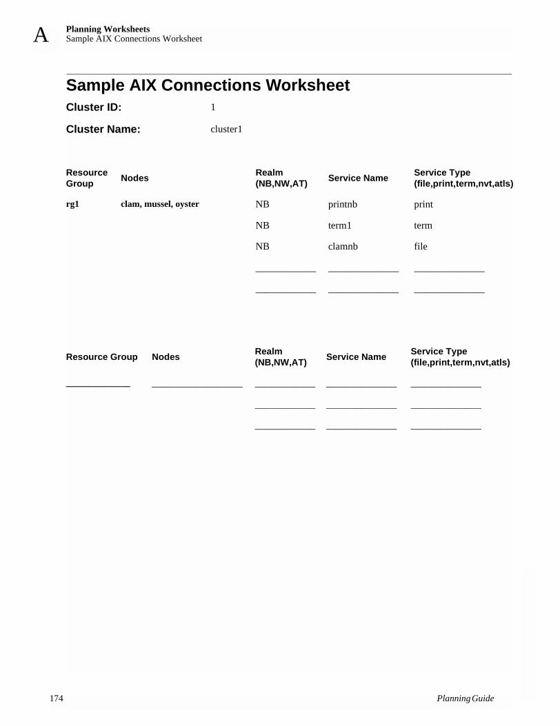
Planning WorksheetsSample AIX Connections Worksheet
17
A
Sample AIX Connections WorksheetCluster ID: 1
Cluster Name: cluster1
Resource Group Nodes Realm
(NB,NW,AT) Service Name Service Type (file,print,term,nvt,atls)
rg1 clam, mussel, oyster NB printnb print
NB term1 term
NB clamnb file
____________ ______________ ______________
____________ ______________ ______________
Resource Group Nodes Realm (NB,NW,AT) Service Name Service Type
(file,print,term,nvt,atls)
______________ __________________ ____________ ______________ ______________
____________ ______________ ______________
____________ ______________ ______________
4 Planning Guide

Planning WorksheetsApplication Server Worksheet A
Application Server WorksheetCluster ID____________
Cluster Name____________
Note: Use full pathnames for all user-defined scripts.
Server Name:
Start Script:
Stop Script:
Server Name:
Start Script:
Stop Script:
Server Name:
Start Script:
Stop Script:
Server Name:
Start Script:
Stop Script:
Planning Guide 175

Planning WorksheetsSample Application Server Worksheet
17
A
Sample Application Server WorksheetCluster ID1
Cluster Nameclus1
Server Name: imagedemo
Start Script: /usr/es/sbin/cluster/utils/start_imagedemo
Stop Script: /usr/es/sbin/cluster/utils/stop_imagedemo
Server Name:
Start Script:
Stop Script:
6 Planning Guide
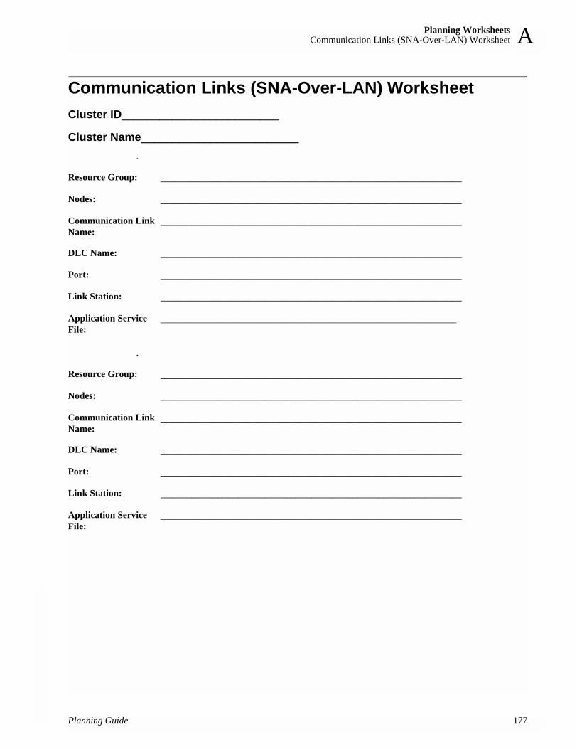
Planning WorksheetsCommunication Links (SNA-Over-LAN) Worksheet A
Communication Links (SNA-Over-LAN) WorksheetCluster ID_________________________
Cluster Name_________________________.
.
Resource Group: __________________________________________________________
Nodes: __________________________________________________________
Communication Link Name:
__________________________________________________________
DLC Name: __________________________________________________________
Port: __________________________________________________________
Link Station: __________________________________________________________
Application ServiceFile:
_________________________________________________________
Resource Group: __________________________________________________________
Nodes: __________________________________________________________
Communication Link Name:
__________________________________________________________
DLC Name: __________________________________________________________
Port: __________________________________________________________
Link Station: __________________________________________________________
Application ServiceFile:
__________________________________________________________
Planning Guide 177

Planning WorksheetsSample Communication Links (SNA-Over-LAN) Worksheet
17
A
Sample Communication Links (SNA-Over-LAN) WorksheetCluster ID_________________________
Cluster Name__cluster1__________________.
.
Resource Group: rg1
Nodes: nodea, nodeb
Communications Link Name:
Link1
DLC Name: profile1
Port(s): port1
Link Station(s): station1
Application ServiceFile:
/tmp/service1.sh
Communications Link Name:
Resource Group:
Nodes:
DLC Name:
Port(s):
Link Station(s):
Application ServiceFile:
8 Planning Guide

Planning WorksheetsCommunication Links (X.25) Worksheet A
Communication Links (X.25) WorksheetCluster ID_________________________
Cluster Name____________________.
Resource Group: __________________________________________________________
Nodes: __________________________________________________________
Communication Link Name:
__________________________________________________________
Port: __________________________________________________________
Address/NUA: __________________________________________________________
Network ID: __________________________________________________________
Country Code __________________________________________________________
Adapter Names(s) __________________________________________________________
Application ServiceFile:
__________________________________________________________
Planning Guide 179

Planning WorksheetsSample Communication Links (X.25) Worksheet
18
A
Sample Communication Links (X.25) Worksheet
Cluster ID__114_______________________
Cluster Name____mycluster________________.
Resource Group: cascrg1
Nodes: nodeA, nodeB
Communication Link Name:
x25link1
Port: sx25a2
Address/NUA: 241
Network ID: 5 (can be left blank)
Country Code (system default automatically used for local country code)
Adapter Names(s) adapterAsx25a2, adapterBsx25a2
Application ServiceFile:
/tmp/startx25.sh
0 Planning Guide
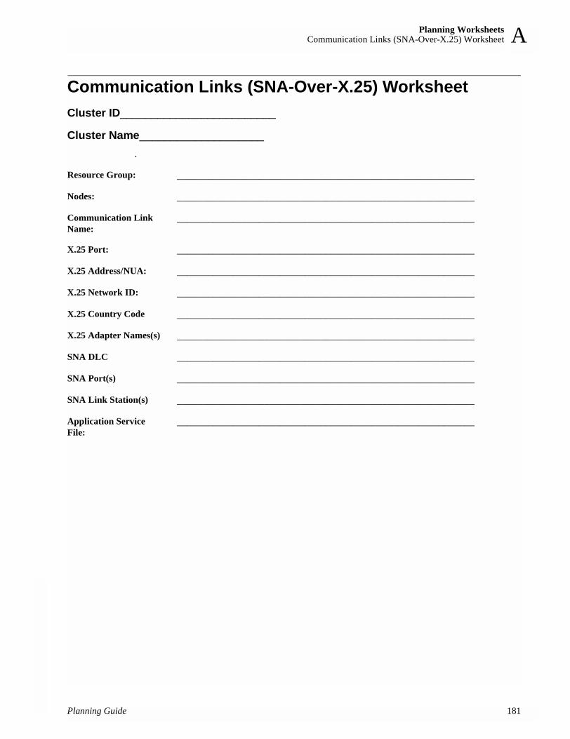
Planning WorksheetsCommunication Links (SNA-Over-X.25) Worksheet A
Communication Links (SNA-Over-X.25) WorksheetCluster ID_________________________
Cluster Name____________________.
Resource Group: __________________________________________________________
Nodes: __________________________________________________________
Communication Link Name:
__________________________________________________________
X.25 Port: __________________________________________________________
X.25 Address/NUA: __________________________________________________________
X.25 Network ID: __________________________________________________________
X.25 Country Code __________________________________________________________
X.25 Adapter Names(s) __________________________________________________________
SNA DLC __________________________________________________________
SNA Port(s) __________________________________________________________
SNA Link Station(s) __________________________________________________________
Application ServiceFile:
__________________________________________________________
Planning Guide 181

Planning WorksheetsSample Communication Links (SNA-Over-X.25) Worksheet
18
A
Sample Communication Links (SNA-Over-X.25) Worksheet
Cluster ID_______114________________
Cluster Name_____mycluster______________.
Resource Group: casc_rg2
Nodes: nodeA, nodeB, nodeC
Communication Link Name:
snax25link1
X.25 Port: sx25a0
X.25 Address/NUA: 241
X.25 Network ID: 5 (can be left blank)
X.25 Country Code (system default automatically used for local country code)
X.25 Adapter Names(s) adapterAsx25a0, adapterBsx25a0, adapterCsx25a0
SNA DLC dlcprofile2
SNA Port(s) snaport2
SNA Link Station(s) snastation2
Application ServiceFile:
/tmp/snax25start.sh
2 Planning Guide

Planning WorksheetsResource Group Worksheet A
Resource Group Worksheet Cluster ID____________Cluster Name____________
Resource Group Name ___________________________
Node Relationship ___________________________
Participating Node Names ___________________________
Service IP Label ___________________________
Filesystems (Default is All) ___________________________
Filesystems Consistency Check ___________________________
Filesystems Recovery Method ___________________________
Filesystems/Directories to Export ___________________________
Filesystems/Directories to NFS Mount ___________________________
Network for NFS Mount ___________________________
Volume Groups ___________________________
Concurrent Volume Groups ___________________________
Raw Disk PVIDs ___________________________
Fast Connect Services ___________________________
Tape Resources ___________________________
Application Servers ___________________________
Highly Available Communications Links ___________________________
Primary Workload Manager Class ___________________________
Secondary Workload Manager Class ___________________________
Miscellaneous Data ___________________________
Inactive Takeover Activated ___________________________
Cascading without Fallback Enabled ___________________________
SSA Disk Fencing Activated ___________________________
Filesystems mounted before IP Configured ___________________________
Processing order: customized or alpha-sort ___________________________
Planning Guide 183

Planning WorksheetsSample Resource Group Worksheet
18
A
Sample Resource Group WorksheetCluster ID1
Cluster Nameclus1
Resource Group Name rotgrp1
Node Relationship rotating
Participating Node Names clam, mussel, oyster
Filesystems /sharedfs1
Filesystems/Directories to Export
Filesystems/Directories to NFS Mount
/sharedvg1
Volume Groups
Raw Disks
AIX Connections Realm/Svc pairs
Tape Resources
Application Servers imagedemo
Inactive Takeover false
Cascade without Fallback false
4 Planning Guide

Planning WorksheetsCluster Event Worksheet A
Cluster Event WorksheetNote: Use full pathnames for all Cluster Event Methods, Notify Commands,
and Recovery commands.
Cluster ID____________
Cluster Name____________
Cluster Event Description ______________________________________
Cluster Event Method ______________________________________
Cluster Event Name ___________________________
Event Command ___________________________
Notify Command ___________________________
Pre-Event Command ___________________________
Post-Event Command ___________________________
Event Recovery Command ___________________________
Recovery Counter ___________________________
Cluster Event Name ___________________________
Event Command ___________________________
Notify Command ___________________________
Pager Notify Message Text ________________________________________________________________________
Pager Notify Message File Location ___________________________
Pre-Event Command ___________________________
Post-Event Command ___________________________
Event Recovery Command ___________________________
Recovery Counter ___________________________
Planning Guide 185

Planning WorksheetsSample Cluster Event Worksheet
18
A
Sample Cluster Event WorksheetNote: Use full pathnames for all user-defined scripts.
Cluster ID1
Cluster Namebivalves
Cluster Event Name node_down_complete
Event Command
Notify Command
Pre-Event Command
Post-Event Command /usr/local/wakeup
Event Recovery Command
Recovery Counter
Cluster Event Name ___________________________
Event Command ___________________________
Notify Command ___________________________
Pager Notify Message Text ___________________________________
____________________________________
Pager Notify Message Location ___________________________
Pre-Event Command ___________________________
Post-Event Command ___________________________
Event Recovery Command ___________________________
Recovery Counter ___________________________
6 Planning Guide

Using the Online Planning Worksheet ProgramOnline Cluster Planning Worksheets: Overview B
Appendix B: Using the Online Planning Worksheet Program
This appendix covers how to use the java-based worksheet program provided with the HACMP software in the /usr/sbin/cluster/samples/worksheets directory. The online worksheet program is a tool to aid you in planning your cluster topology and resource configuration and then applying the configuration directly to your cluster. You can run the program in either a Microsoft Windows™ or an AIX environment.
This appendix contains instructions for using the java-based online worksheets correctly, and references to the appropriate chapters in this book for detailed information about each stage of the cluster planning process. The worksheet program includes its own online help topics as well.
Before you start, and while you are using the online worksheet program, refer to the chapters earlier in this guide for more information about how to plan each component of your cluster. Also consider drawing a diagram of your desired configuration before you get started, as suggested in Chapter 2: Drawing the Cluster Diagram.
Online Cluster Planning Worksheets: OverviewThe HACMP online cluster planning “worksheets” are actually a series of java-based panels. Each panel contains fields in which you can specify the basic components of your HACMP cluster topology and resource configuration. As you progress through the panels, you can save information you have entered, create an HTML report to print out or e-mail, or go back to earlier panels and make changes.
The online planning panels present logical default choices whenever possible. When appropriate, the worksheet program prevents you from entering nonfeasible configuration choices by presenting only the options that work based on what you have already entered, or by presenting a message if you make an invalid choice.
The panels are based loosely on the paper worksheets that have always been provided in the HACMP documentation (see Appendix A: Planning Worksheets). The information in the online worksheets has been consolidated and ordered in a slightly different sequence than the paper worksheets. Therefore, the specific worksheet instructions in the earlier planning chapters apply only to the paper worksheets; the conceptual information applies whether you use paper or online worksheets.
As soon as you complete the series of planning worksheets, you can actually apply the new configuration to your cluster nodes.
Installing and Viewing the Worksheet ProgramThe online planning worksheet program files are packaged with your other HACMP filesets, in the samples directory.
Planning Guide 187

Using the Online Planning Worksheet ProgramInstalling and Viewing the Worksheet Program
18
B
Prerequisites for the Online Worksheet ProgramTo use the worksheets, your system must meet the following requirements:• One of the following operating systems:
• AIX 5.1 or higher• Windows 95/98, NT, 2000
• Java 2 Runtime Environment (J2RE) version 1.2 or higher. AIX installs the J2RE by default. If you run the program on Windows, check to see that the appropriate J2RE is installed. You may need to install a Java virtual machine in order to use the online worksheet program.
Installing and Running the Online Worksheet Program on AIXTo begin using the online cluster planning worksheets on AIX:
1. Install the HACMP software.
2. By default, the cluster planning worksheets are installed in the /usr/sbin/cluster/samples/worksheets directory.
3. To run the application, execute the file:/usr/sbin/cluster/samples/worksheets/worksheetsThe program first verifies that you have an appropriate version of the J2RE installed and then runs the application in the background.
Note: The file /usr/sbin/cluster/samples/worksheets/worksheets.jar is the Java archive that contains the class files of the application. If you move this file to a different location then you must edit the /usr/sbin/cluster/samples/worksheets/worksheets file so that the WORKSHEETS variable is set to the correct full path of the worksheets.jar file. You do not have to modify the WORKSHEETS variable if you only move the worksheets file to a different location.
Installing and Running the Online Worksheet Program on WindowsTo begin using the online cluster planning worksheets on a Windows system:
1. Install the HACMP software on the AIX machine.
2. By default, the cluster planning worksheets are installed in the /usr/sbin/cluster/samples/worksheets directory.
3. Transfer the files worksheets.bat and worksheets.jar (via FTP or other appropriate method) to a folder of your choice on your Windows system. Be sure to specify binary mode for your FTP session.
4. If you do not have the worksheets.bat and worksheets.jar files in the same directory, then you need to edit the worksheets.bat file so that the WORKSHEETS variable is set to the full path of the worksheets.jar file.
8 Planning Guide

Using the Online Planning Worksheet ProgramThe Online Worksheet Format B
5. Run the application by executing the worksheets.bat file. You can run this file from a DOS command prompt window or by double clicking on the worksheets.bat file on your desktop or in a Windows file Explorer window.
Note: Do not close the DOS shell window that the application is launched from. Closing the shell window will cause Java to close the application.
Note: You do not need to edit the CLASSPATH environment variable to run the cluster planning worksheets application.
Refer to the online help topics within the worksheet program and the HACMP documentation to begin planning and configuring your cluster.
The Online Worksheet FormatThe online planning worksheet panels are arranged in a sequence that makes logical sense for planning your cluster topology and resources. In many cases, you must follow this sequence for correct configuration.
As you proceed through the worksheet panels, refer to the instructions on the following pages and on the worksheet panels, and refer to the specified chapters in this Guide for important information about planning each component. In addition, online help topics provide details about each worksheet panel.
Panels, Tabs, and ButtonsThe first panel you see when you open the worksheet program is the Cluster panel shown here. In this initial panel, you see the tabs that take you to individual worksheets for data entry. You also see several buttons. Most of the tabs and buttons are disabled until you enter the cluster name and ID or open an existing set of worksheets with data already in them.
Planning Guide 189

Using the Online Planning Worksheet ProgramThe Online Worksheet Format
19
B
The Initial Worksheet Panel
TabsThe tabs on the bottom and top of the panel indicate at all times which worksheet panels are enabled; the panel currently selected is indicated by bold type on the appropriate tabs. The tabs at the bottom of the screen indicate the major topics, and those at the top indicate subtopics within each major topic.
Bottom TabsThe tabs at the bottom of your screen indicate three major planning topics. You should proceed with your configuration in the sequence of the tabs as follows:
1. Topology
2. Disk
3. Resources
The Cluster Notes tab brings to you a screen for miscellaneous user/system administrator notes.
The Help tab brings you to a directory of help topics for specific worksheets.
Top TabsWhen you select a major topic from the bottom tabs, a series of subtopic tabs at the top of your screen are enabled. Again, these tabs are presented from left to right in the order that works best for planning a cluster.
0 Planning Guide

Using the Online Planning Worksheet ProgramThe Online Worksheet Format B
The entire set of planning sheets follows this hierarchy of topics and subtopics:
Worksheet Panel ButtonsWithin each panel, buttons are used for the following actions:
Note: Be aware that functions such as “delete” may become invisible at times for components that are used by other items in the configuration. For instance, if you have NetworkA defined, and you have adapters defined on that network, then the “delete” button for NetworkA is invisible until you delete all the adapters defined for it.
Base Panel ButtonsOn the base panel, which is visible at all times below the topic tabs, the following buttons are available:
Topology: Cluster, Node, Network, Global Network (active for HACMP/ES type only), Adapters
Disk: Disks, Volume Groups, Logical Volumes, NFS Exports
Resource: Cluster Events, Applications, Application Servers, Resource Groups, Resource Associations
Cluster Notes: Space for administrator notes
Help: All help topics
Add Updates the configuration with the information in the current entry field and makes the information available to subsequent panels.
Modify Allows you to make changes in any entry you have made in the current worksheet panel. First, in the lower window, select what entry you wish to change. The data for that entry is displayed in the current entry fields. Make the desired changes and press the Modify button.
Delete Deletes the selected entry field data.
Clear All Deletes all entries in the entire set of worksheets you have open
Create Report Saves to an HTML file all of the configuration data you have entered thus far for the set of worksheets currently open. You can then open this file in a browser and print it or distribute it via e-mail to others.
Save Writes the cluster configuration entered thus far to the PC disk, to a specified worksheet (.ws) file.*
Create Configuration Creates the AIX file that you will transfer to an AIX cluster node to apply the configuration data to the cluster.
Planning Guide 191

Using the Online Planning Worksheet ProgramEntering Cluster Configuration Data
19
B
Select the Help tab at any time to get specific information about entering data in a given worksheet panel.
Note: Due to differences in older and newer versions of msjava.dll, the behavior of the Save option may vary. In newer versions of msjava.dll, the .ws files can be saved only to the desktop.
Entering Cluster Configuration DataIf you are familiar with the planning information in the earlier chapters of this guide, and have your cluster configuration preferences mapped out in a diagram or other format, you are ready to begin entering data into the online worksheet panels as follows.
As noted above, be aware that functions such as “delete” may become invisible at times for components that are used by other items in the configuration. For instance, if you have NetworkA defined, and you have adapters defined on that network, then the “delete” button for NetworkA is invisible until you delete all the adapters defined for it.
Stage 1: Topology PlanningThe first step is to define the topology of your cluster: the framework of cluster nodes and the networks that connect them.
ClusterWhen you open the worksheet program, the first thing you see is the Cluster screen.
In the Cluster screen, you name your cluster and assign it an ID. You also specify which product subsystem you are using: HACMP or HACMP/ES. After you have entered the name and ID, you can choose from the subtopics on the top tabs. The Author and Company fields are optional. You can also open the worksheets for an existing cluster you have already started and saved.
To complete the Cluster worksheet:
1. Fill in the cluster name. This can have any combination of 31 or fewer alphanumeric characters and underscores, but cannot have a leading numeric. Start the name with a letter.
2. Fill in the cluster ID. The ID can be any positive integer up to 99999.
Note: Be sure the cluster name and ID do not duplicate those of another cluster at your site.
3. Check the appropriate box (HACMP or HACMP/ES) for the product type (subsystem) you are using.
4. Press the Add button. For more information, see Naming the Cluster.
Note: If you want to change what you have entered in the Cluster panel, just change your text and press Add again, except for Type (HACMP or HACMP/ES). If you need to change the Type designation after you have hit Add, use the Clear All button to start over.
2 Planning Guide

Using the Online Planning Worksheet ProgramEntering Cluster Configuration Data B
NodesIn the Nodes screen, you specify all nodes that will participate in the cluster. The maximum number of nodes is eight (HACMP) or 32 (HACMP/ES). The minimum is two for either case. For more information, see Selecting the Number of Nodes.
To specify cluster nodes, enter each node name and press the Add button. When you have finished this panel, go on to the Networks panel.
Networks In this screen, you define the networks in your cluster. The drop-down list for attributes presents only the attributes that are possible for the network type you select. For example, if your network type is Ethernet, you can choose either public or private as an attribute. For an RS232 serial network, only serial is presented. Refer to Chapter 3: Planning TCP/IP Networks and Chapter 4: Planning Serial Networks for more information.
Global NetworkThis panel is enabled only if you selected the type HACMP/ES in the first panel.
For more information about global networks and the HACMP/ES subsystem, see the Enhanced Scalability Installation and Administration Guide.
Adapters In this screen, you enter information about the adapters for each network you have defined. The Networks drop-down list presents a list of the networks you have defined.
The worksheet program allows you to enter adapter functions and hardware addresses that work with the types of networks you have defined. Refer to Chapter 3: Planning TCP/IP Networks and Chapter 4: Planning Serial Networks for more information.
Stage 2: Disk PlanningOnce you have defined the major components of your cluster topology, the next step is to plan your shared disk configuration.
DisksIn this screen, you enter information about the disks you want to use in your cluster. Refer to Chapter 5: Planning Shared Disk and Tape Devices. Additional information can be found in the Concepts and Facilities Guide.
Volume GroupsIn this screen, you specify the volume groups for your cluster. See Chapter 6: Planning Shared LVM Components.
Logical VolumesIn the Logical Volumes screen, you specify logical volumes and which volume groups they are associated with. See Chapter 6: Planning Shared LVM Components. For additional information, refer to AIX System Management Guide: Operating System and Devices.
Planning Guide 193

Using the Online Planning Worksheet ProgramEntering Cluster Configuration Data
19
B
NFS ExportsHere, you specify which filesystems, if any, need to be exported, so other nodes can NFS mount them. Refer to Chapter 6: Planning Shared LVM Components.
Stage 3: Resource Planning Now that you have planned the nodes, networks, and disk components for your cluster, you move on to specifying event scripts and configuring the cluster resources you wish to make highly available under HACMP.
Cluster EventsIn this screen, you specify events and associated scripts. You type in the command or script path for each event. You can enter multiple entries per event per node. Note that you cannot enter a duplicate command for the same event. Refer to Chapter 8: Tailoring Cluster Event Processing.
ApplicationsIn the Applications screen, you assign a name to each application and enter its directory path and filesystem. Refer to Chapter 7: Planning Applications, Application Servers, and Resource Groups.
Application ServersHere, you specify the application server name, and then choose from the pick list of applications you specified in the previous screen. You then specify the full path locations of your application start and stop scripts. In addition, you can write notes about your scripts in the space provided. Refer to Chapter 7: Planning Applications, Application Servers, and Resource Groups.
Resource GroupsIn this screen, you assign names to your resource groups and specify the participating nodes and their position (priority), if appropriate, in the resource chain.
The Increase Priority and Decrease Priority buttons become visible when you highlight the node name. Note that for concurrent and rotating resource groups, priority information is not valid. Refer to Chapter 7: Planning Applications, Application Servers, and Resource Groups.
Resource AssociationsIn this screen, you specify which individual resources—such as filesystems, IP labels, volume groups, and application servers—are to be part of each resource group you defined in the previous screen. Refer to Chapter 7: Planning Applications, Application Servers, and Resource Groups.
Cluster NotesIn this screen, you have space to note any special details about the cluster or your cluster planning process for future reference.
4 Planning Guide

Using the Online Planning Worksheet ProgramApplying Worksheet Data to AIX Cluster Nodes B
Applying Worksheet Data to AIX Cluster NodesWhen you have completed all the worksheets, are satisfied with your decisions, and have saved the worksheets, you can create an AIX file to configure your actual cluster. If you are on a Windows system, you then transfer the configuration file, via FTP, to your AIX cluster nodes.
Prerequisites Before you can transfer or apply your new file to your AIX nodes, be sure the following conditions are in place:• Your HACMP software must be installed.• All hardware devices that you specified for your cluster configuration must be in place.• If you are replacing an existing configuration, any current cluster ODM information should
be retained in a snapshot. • Cluster services must be stopped on all nodes.
Creating the AIX Configuration FileTo create an AIX file of your cluster configuration data:
1. Press the Create Configuration button located on the base panel. (Note that this button is enabled only after you have defined the cluster nodes.) The Create AIX Cluster Configuration dialog box appears.
2. Save your configuration file as the default name (cluster.conf) or any name you choose.
Transferring the AIX File from a Windows Environment to the ClusterUse FTP to transfer the configuration data file from a Windows system to one of the AIX cluster nodes.
Applying the AIX Configuration FileOnce you have the AIX configuration file on the system (either creating it on the HACMP node or transferring it from a Windows Environment), run the cl_opsconfig command as follows:/usr/sbin/cluster/utilities/cl_opsconfig <your_config_file>
The cl_opsconfig utility automatically performs a synchronization, including verification, of the configuration. During this process, you see a series of messages indicating the events taking place and any warnings or errors.
Boot Adapter WarningsThe cl_opsconfig utility adds all boot adapters before adding any service adapters. Because of this, you see a series of warnings indicating “There is no service interface” for each boot adapter as it is added. You can ignore these warnings if you have configured the proper service adapters, as cl_opsconfig will add them later in the process, resolving the false error.
Planning Guide 195

Using the Online Planning Worksheet ProgramWhere You Go From Here
19
B
Viewing Error MessagesYou can view the cl_opsconfig error messages on the screen, or redirect them to a log file. If you wish to redirect the standard error information to another file, add the symbols 2> and specify an output file, as in the following:
/usr/sbin/cluster/utilities/cl_opsconfig <your_config_file> 2> <output file>
Note that redirecting all output (standard output and standard error) is not recommended.
If errors are detected, go back to the worksheet program to fix the problems, and repeat the process of creating the configuration file, transferring it to the cluster node, and running cl_opsconfig.
Where You Go From HereWhen your configuration file has been transferred and cl_opsconfig has run successfully without reporting configuration errors, your cluster has a basic working HACMP configuration.
You can now proceed to additional configuration and customization tasks—for example, configuring AIX Error Notification, run time parameters, custom scripts, and so on. For more information, refer to the appropriate chapters in this guide, and also in the Installation Guide and the Administration Guide.
6 Planning Guide

Single-Adapter Networksnetmon Enhancement for Single-Adapter Networks C
Appendix C: Single-Adapter NetworksThis appendix describes an enhancement to the netmon program for use in a cluster with single-adapter networks.
netmon Enhancement for Single-Adapter NetworksSingle-adapter networks (networks with no standby adapters) are not recommended for an HACMP environment. In cluster configurations where there are networks with no standby network adapters, it can be difficult for the HACMP software to accurately determine service adapter failure. This is because the Cluster Manager cannot use a standby adapter to force packet traffic over the service adapter to verify its operation. This shortcoming is less of an exposure if one or both of the following conditions is true:• There are network devices that answer broadcast ICMP ECHO requests. This can be
verified by pinging the broadcast address and determining the number of different IP addresses that respond.
• The service adapter is under heavy use. In this instance the inbound packet count will continue to increase over the service adapter without stimulation from the Cluster Manager.
An enhancement to netmon, the network monitor portion of the Cluster Manager, allows more accurate determination of a service adapter failure. This function can be used in configurations that require a single service adapter per network.
You can create a netmon configuration file, /usr/sbin/cluster/netmon.cf, that specifies additional network addresses to which ICMP ECHO requests can be sent. The configuration file consists of one IP address or IP label per line. The maximum number of addresses used is five. All addresses specified after the fifth one will be ignored. No comments are allowed in the file.
Here’s an example of a /usr/sbin/cluster/netmon.cf configuration file:180.146.181.119steamerchowder180.146.181.121mussel
This file must exist at cluster startup. The cluster software scans the configuration file during initialization. When netmon needs to stimulate the network to verify adapter function, it sends ICMP ECHO requests to each address. After sending the request to every address, netmon checks the inbound packet count before determining whether an adapter has failed.
Planning Guide 197

Single-Adapter Networksnetmon Enhancement for Single-Adapter Networks
19
C
8 Planning Guide

Applications and HACMPOverview D
Appendix D: Applications and HACMPThis appendix addresses some of the key issues to consider when making your applications highly available under HACMP. The information provided here is of a general enough nature to apply to both the HACMP and HACMP/ES product subsystems.
Also see Chapter 7: Planning Applications, Application Servers, and Resource Groups in this guide, and the chapter on configuring cluster resources in the Installation Guide.
OverviewBesides understanding the hardware and software needed to make a cluster highly available, you will need to spend some time on application considerations when planning your HACMP environment. The goal of clustering is to keep your important applications available despite any single point of failure. To achieve this goal, it is important to consider the aspects of an application that make it recoverable under HACMP.
There are few hard and fast requirements that an application must meet to recover well under HACMP. For the most part, there are simply good practices that can head off potential problems. Some required characteristics, as well as a number of suggestions, are discussed here. These are grouped according to key points that should be addressed in all HACMP environments. This appendix covers the following application considerations:• Automation—making sure your applications start and stop without user intervention• Dependencies—knowing what factors outside HACMP affect your applications• Interference—knowing that applications themselves can hinder HACMP’s functioning• Robustness—choosing strong, stable applications• Implementation—using appropriate scripts, file locations, and cron schedules
At the end of this appendix, you will find two examples of popular applications—Oracle Database™ and SAP R/3™—and some issues to consider when implementing these applications in an HACMP environment.
Application Automation: Minimizing Manual InterventionOne key requirement for an application to function successfully under HACMP is that the application be able to start and stop without any manual intervention.
Application Start ScriptsYou should create a start script that completely starts the application. Configure HACMP to call this script at cluster startup to initially bring the application online. Since the cluster daemons call the start script, there is no option for interaction. Additionally, upon an HACMP fallover, the recovery process calls this script to bring the application on line on a standby node. This allows for a fully automated recovery.
Planning Guide 199

Applications and HACMPApplication Automation: Minimizing Manual Intervention
20
D
Keep in mind that this application start script may need to take additional action to prepare the cluster to bring the application on line. The start script will be called by HACMP as the “root” user. It may be necessary to change to a different user in order to start the application. The su command can accomplish this. Also, it may be necessary to run nohup on commands that are started in the background and have the potential to be terminated upon exit of the shell.
For example, an HACMP cluster node may be a client in a Network Information Service (NIS) environment. If this is the case, and you need to use the su command to change user id, there must be a route to the NIS master at all times. In the event that a route doesn’t exist, and the su is attempted, the application script hangs. You can avoid this by enabling the HACMP cluster node to be an NIS slave. That way a cluster node has the ability to access its own NIS map files to validate a user ID.
Another good practice in application start scripts is to check the return code upon exiting a script. If the return code is not zero, an error may have occurred in starting that should be addressed. If a non-zero return code is passed back to HACMP, the event_error event is run and the cluster enters an error state. This check alerts administrators that the cluster is not functioning properly.
The start script should also check for the presence of required resources or processes. This will ensure an application can start successfully. If the necessary resources are not available, a message can be sent to the administration team to correct this and restart the application.
Keep in mind that the start script may be run after a primary node has failed. There may be recovery actions necessary on the backup node in order to restart an application. This is common in database applications. Again, the recovery must be able to run without any interaction from administrators.
WARNING:Be careful not to kill any HACMP processes as part of your script! If you are using the output of the ps command and using a grep to search for a certain pattern, make sure the pattern does not match any of the HACMP or RSCT processes.
Application Stop ScriptsThe most important aspect of an application stop script is that it completely stop an application. Failure to do so many prevent HACMP from successfully completing a takeover of resources by the backup nodes. In stopping, the script may need to address some of the same concerns the start script addresses, such as NIS and the su command.
The application stop script should use a phased approach. The first phase should be a graceful attempt to stop the processes and release any resources. If processes refuse to terminate, the second phase should be used to forcefully ensure all processing is stopped. Finally, a third phase can use a loop to repeat any steps necessary to ensure that the application has terminated completely.
Also see the notes in the section Writing Effective Scripts.
Keep in mind that HACMP allows six minutes by default for events to complete processing. A message indicating the cluster has been in reconfiguration too long appears until the cluster completes its reconfiguration and returns to a stable state. This warning may be an indication that a script is hung and requires manual intervention. If this is a possibility, you may wish to
0 Planning Guide

Applications and HACMPApplication Dependencies D
consider stopping an application manually before stopping HACMP. If desired, you can alter the time period before the config_too_long event is invoked. See the Troubleshooting Guide for more information.
Application Tier IssuesOften, applications are of a multi-tier architecture. The first tier may be a database, the second tier an application/login tier and the third a client. You must consider all tiers of an architecture if one or more is made highly available through the use of HACMP.
For example, if the database is made highly available, and a fallover occurs, consider whether actions should be taken at the higher tiers in order to automatically return the application to service. If so, it may be necessary to stop and restart application or client tiers. This can be facilitated in one of two ways. One way is to run clinfo on the tiers, the other is to use the rsh command.
Using the Clinfo APIclinfo is the cluster information daemon. You can write a program using the Clinfo API to run on any tiers that would stop and restart an application after a fallover has completed successfully. In this sense, the tier, or application, becomes “cluster aware,” responding to events that take place in the cluster. For more information on the Clinfo API, see Programming Client Applications.
Using Pre- and Post-Event ScriptsAnother way to address the issue of multi-tiered architectures is to use pre- and post-event scripts around a cluster event. These scripts would call the rsh command to stop and restart the application. Keep in mind that the use of the rsh command may require a loosening of security that is unacceptable for some environments.Another way to address the rsh security issue is by using Kerberos as an authentication method. If you choose this method, Kerberos must be in place prior to the HACMP installation and configuration. IBM supports Kerberos on IBM Scalable POWERParallel (RS/6000 SP) systems. For more information about configuring Kerberos, see the appendix on the SP in the Installation Guide.
Application DependenciesIn many cases, applications depend on more than data and an IP address. For the success of any application under HACMP, it is important to know what the application should not depend upon in order to function properly. This section outlines many of the major dependency issues. Keep in mind that these dependencies may come from outside the HACMP and application environment. They may be incompatible products or external resource conflicts. Look beyond the application itself to potential problems within the enterprise.
Locally Attached DevicesLocally attached devices can pose a clear dependency problem. In the event of a fallover, if these devices are not attached and accessible to the standby node, an application may fail to run properly. These may include a CD-ROM device, a tape device, or an optical juke box. Consider whether your application depends on any of these and if they can be shared between cluster nodes.
Planning Guide 201

Applications and HACMPApplication Interference
20
D
Hard CodingAnytime an application is hard coded to a particular device in a particular location, there is the potential for a dependency issue. For example, the console is typically assigned as /dev/tty0. Although this is common, it is by no means guaranteed. If your application assumes this, ensure that all possible standby nodes have the same configuration.
Hostname DependenciesSome applications are written to be dependent on the AIX hostname. They issue a command in order to validate licenses or name file systems. The hostname is not an IP address label. The hostname is specific to a node and is not failed over by HACMP. It is possible to manipulate the hostname, or use hostname aliases, in order to trick your application, but this can become cumbersome when other applications, not controlled by HACMP, also depend on the hostname.
Software LicensingAnother possible problem is software licensing. Software can be licensed to a particular CPU ID. If this is the case with your application, it is important to realize that a fallover of the software will not successfully restart. You may be able to avoid this problem by having a copy of the software resident on all cluster nodes. Know whether your application uses software that is licensed to a particular CPU ID.
Application InterferenceSometimes an application or an application environment may interfere with the proper functioning of HACMP. An application may execute properly on both the primary and standby nodes. However, when HACMP is started, a conflict with the application or environment may arise that prevents HACMP from functioning successfully.
Software Using IPX/SPX ProtocolA conflict may arise between HACMP and any software that binds a socket over a network interface. An example is the IPX/SPX protocol. When active, it binds an interface and prevents HACMP from properly managing the interface. Specifically, for ethernet and token ring, it inhibits the hardware address takeover from completing successfully. A “device busy” message appears in the HACMP logs. The software using IPX/SPX must be either completely stopped or not used in order for hardware address takeover to work.
Products Manipulating Network RoutesAdditionally, products that manipulate network routes can keep HACMP from functioning as it was designed. These products can find a secondary path through a network that has had an initial failure. This may prevent HACMP from properly diagnosing a failure and taking appropriate recovery actions.
AIX Connections and AIX Fast ConnectYou can reduce the problem of conflict with certain protocols, and the need for manual intervention, if you are using AIX Connections or AIX Fast Connect for AIX to share resources. The protocols handled by these applications can easily be made highly available because of their integration with HACMP.
2 Planning Guide

Applications and HACMPRobustness of Application D
AIX Connections is a network operating software that enables sharing of resources between AIX workstations and clients running other operating systems such as Windows NT, OS/2, and Macintosh. AIX Connections is already integrated with HACMP so the IPX/SPX, NetBEUI, and AppleTalk protocols handled by AIX Connections can be easily configured as highly available resources in the cluster. The protocols can then be taken over in the event of node or adapter failure. For example, in the case of a NetWare client using the IPX/SPX protocol, if AIX Connections is configured, HACMP steps up in the event of an adapter failure: it stops communications on the port, frees up the bind on the socket—thereby allowing the address takeover to proceed—and restarts the communication. AIX Fast Connect software is integrated with HACMP in a similar way, so that it can be configured as a highly available resource. AIX Fast Connect allows you to share resources between AIX workstation and PCs running Windows, DOS, and OS/2 operating systems. Fast Connect supports the NetBIOS protocol over TCP/IP.
For more information on configuring these applications as resources in HACMP, see Chapter 7: Planning Applications, Application Servers, and Resource Groups in this book, and the sections on configuring resources in the Installation Guide. You’ll also find worksheets for these applications in Appendix A: Planning Worksheets.
Robustness of ApplicationOf primary importance to the success of any application is the health, or robustness, of the application. If the application is unstable or crashing intermittently, you should be sure these issues are resolved prior to placing it in a high availability environment.
Beyond basic stability, an application under HACMP should meet other robustness characteristics, such as the following.
Successful Restart After Hardware FailureA good application candidate for HACMP should be able to restart successfully after a hardware failure. Run a test on an application prior to putting in under HACMP. Run the application under a heavy load and fail the node. What does it take to recover once the node is back on line? Can this recovery be completely automated? If not, the application may not be a good candidate for high availability.
Survival of Real Memory LossFor an application to function well under HACMP it should be able to survive a loss of the contents of real memory. It should be able to survive the loss of the kernel or processor state. When a node failure occurs, these are lost. Applications should also regularly check-point the data to disk. In the event that a failure occurs, the application will be able to pick up where it last check-pointed data, rather than starting completely over.
Planning Guide 203

Applications and HACMPApplication Implementation Strategies
20
D
Application Implementation StrategiesThere are a number of aspects of an application that you should consider as you plan for implementing it under HACMP. You must consider characteristics such as time to start, time to restart after failure, and time to stop. Your decisions in a number of areas, including those discussed in this section—scriptwriting, file storage, /etc/inittab file and cron schedule issues—can improve the probability of successful application implementation.
Writing Effective ScriptsWriting smart application start scripts can also help you avoid problems with bringing applications online.
A good practice for start scripts is to check prerequisite conditions before starting an application. These may include access to a filesystem, adequate paging space and free filesystem space. The start script should exit and run a command to notify system administrators if the requirements are not met.
When starting a database it is important to consider whether there are multiple instances within the same cluster. If this is the case, you must be careful to start only the instances applicable for each node. Certain database startup commands read a configuration file and start all known databases at the same time. This may not be a desired configuration for all environments.
WARNING:Be careful not to kill any HACMP processes as part of your script! If you are using the output of the ps command and using a grep to search for a certain pattern, make sure the pattern does not match any of the HACMP or RSCT processes.
Considering File Storage LocationsYou should also give thought to where the configuration files reside. They could either be on shared disk, and thus potentially accessed by whichever node has the volume group varied on, or on each node’s internal disks. This holds true for all aspects of an application. Certain files must be on shared drives. These include data, logs, and anything that could be updated by the execution of the application. Files such as configuration files or application binaries could reside in either location.
There are pros and cons to storing optional files in either location. Having files stored on each node’s internal disks implies that you have multiple copies of, and potentially multiple licenses for, the application. This could require additional cost as well as maintenance in keeping these files synchronized. However, in the event that an application needs to be upgraded, the entire cluster need not be taken out of production. One node could be upgraded while the other remains in production. The “best” solution is the one that works best for a particular environment.
Considering /etc/inittab and cron Table IssuesYou must also give thought to applications, or resources needed by an application, that either start out of the /etc/inittab file or out of the cron table. The inittab starts applications upon boot up of the system. If cluster resources are needed for an application to function, they will not
4 Planning Guide
Applications and HACMPExamples: Oracle Database™ and SAP R/3™ D
become available until after HACMP is started. It is better to use the HACMP application server feature which allows the application to be a resource that is started only after all dependent resources are online.
In the cron table, jobs are started according to a schedule set in the table and the date setting on a node. This information is maintained on internal disks and thus cannot be shared by a standby node. You must synchronize these cron tables so that a standby node can perform the necessary action at the appropriate time. You must also ensure the date is set the same on the primary node and any of its standby nodes.
Examples: Oracle Database™ and SAP R/3™Here are two examples illustrating issues to consider in order to make the applications Oracle Database and SAP R/3 function well under HACMP.
Example 1: Oracle DatabaseThe Oracle Database, like many databases, functions very well under HACMP. It is a robust application that handles failures well. It can roll back uncommitted transactions after a fallover and return to service in a timely manner. There are, however, a few things to keep in mind when using Oracle Database under HACMP.
Starting OracleOracle must be started by the Oracle user ID. Thus, the start script should contain an su - oracleuser. The dash (-) is important since the su needs to take on all characteristics of the Oracle user and reside in the Oracle user’s home directory. The full command might look something like this:su - oracleuser -c “/apps/oracle/startup/dbstart”
Commands like dbstart and dbshut read the /etc/oratabs file for instructions on which database instances are known and should be started. In certain cases it is inappropriate to start all of the instances, because they might be owned by another node. This would be the case in the mutual takeover of two Oracle instances. The oratabs file typically resides on the internal disk and thus cannot be shared. If appropriate, consider other ways of starting different Oracle instances.
Stopping OracleThe stopping of Oracle is a process of special interest. There are several different ways to ensure Oracle has completely stopped. The recommended sequence is this: first, implement a graceful shutdown; second, call a shutdown immediate, which is a bit more forceful method; finally, create a loop to check the process table to ensure all Oracle processes have exited.
Oracle File StorageThe Oracle product database contains several files as well as data. It is necessary that the data and redo logs be stored on shared disk so that both nodes may have access to the information. However, the Oracle binaries and configuration files could reside on either internal or shared disks. Consider what solution is best for your environment.
Planning Guide 205

Applications and HACMPExamples: Oracle Database™ and SAP R/3™
20
D
For more information about keeping your Oracle applications highly available, see the IBM Redbook #SG24-4788, Bullet-Proofing Your Oracle Database with HACMP: A Guide to Implementing AIX Databases with HACMP. This and other redbooks can be found online at http://www.redbooks.ibm.com/
Example 2: SAP R/3, a Multi-Tiered ApplicationSAP R/3 is an example of a three-tiered application. It has a database tier, an application tier, and a client tier. Most frequently, it is the database tier that is made highly available. In such a case, when a fallover occurs and the database is restarted, it is necessary to stop and restart the SAP application tier. You can do this in one of two ways: by using the rsh command, or by making the application tier nodes “cluster aware.”
Using the rsh CommandThe first way to stop and start the SAP application tier is to create a script that performs an rsh to the application nodes. The application tier of SAP is stopped and then restarted. This is done for every node in the application tier. Use of the rsh command requires a method of allowing the database node access to the application node. Certain methods, such as the use of /.rhosts files, pose a security risk and may not be desirable. As mentioned under Application Tier Issues, another way to address the rsh security issue is by using Kerberos as an authentication method. If you choose this method, Kerberos must be in place prior to the HACMP installation and configuration. IBM supports Kerberos on IBM Scalable POWERParallel (RS/6000 SP) systems. For more information about configuring Kerberos, see Appendix F of the Installation Guide.
Making Application Tier Nodes “Cluster Aware”A second method for stopping and starting the application tier is to make the application tier nodes “cluster aware.” This means that the application tier nodes are aware of the clustered database and know when a fallover occurs. You can implement this by making the application tier nodes either HACMP servers or clients. If the application node is a server, it runs the same cluster events as the database nodes to indicate a failure; pre- and post-event scripts could then be written to stop and restart the SAP application tier. If the application node is an HACMP client, it is notified of the database fallover via SNMP through the cluster information daemon (clinfo). A program could be written using the Clinfo API to stop and restart the SAP application tier.See Programming Client Applications for more detail on the Clinfo API.
6 Planning Guide

Notices for HACMP Planning Guide
Notices for HACMP Planning Guide This information was developed for products and services offered in the U.S.A.
IBM may not offer the products, services, or features discussed in this document in other countries. Consult your local IBM representative for information on the products and services currently available in your area. Any reference to an IBM product, program, or service is not intended to state or imply that only that product, program, or service may be used. Any functionally equivalent product, program, or service that does not infringe any IBM intellectual property right may be used instead. However, it is the user’s responsibility to evaluate and verify the operation of any non-IBM product, program, or service.
IBM may have patents or pending patent applications covering subject matter described in this document. The furnishing of this document does not give you any license to these patents. You can send license inquiries, in writing, to:
IBM Director of LicensingIBM CorporationNorth Castle DriveArmonk, NY 10504-1785U.S.A.
For license inquiries regarding double-byte (DBCS) information, contact the IBM Intellectual Property Department in your country or send inquiries, in writing, to:
IBM World Trade Asia CorporationLicensing2-31 Roppongi 3-chome, Minato-kuTokyo 106, Japan
The following paragraph does not apply to the United Kingdom or any country where such provisions are inconsistent with local law: INTERNATIONAL BUSINESS MACHINES CORPORATION PROVIDES THIS PUBLICATION “AS IS” WITHOUT WARRANTY OF ANY KIND, EITHER EXPRESSED OR IMPLIED, INCLUDING, BUT NOT LIMITED TO, THE IMPLIED WARRANTIES OF NON-INFRINGEMENT, MERCHANTABILITY OR FITNESS FOR A PARTICULAR PURPOSE. Some states do not allow disclaimer of express or implied warranties in certain transactions; therefore, this statement may not apply to you.
This information could include technical inaccuracies or typographical errors. Changes are periodically made to the information herein; these changes will be incorporated in new editions of the publication. IBM may make improvements and/or changes in the product(s) and/or the program(s) described in this publication at any time without notice.
IBM may use or distribute any of the information you supply in any way it believes appropriate without incurring any obligation to you.
Licensees of this program who wish to have information about it for the purpose of enabling: (i) the exchange of information between independently created programs and other programs (including this one) and (ii) the mutual use of the information which has been exchanged, should contact:
Planning Guide

Notices for HACMP Planning Guide
IBM CorporationDept. LRAS / Bldg. 00311400 Burnet RoadAustin, TX 78758-3493U.S.A.
Such information may be available, subject to appropriate terms and conditions, including in some cases, payment of a fee.
The licensed program described in this document and all licensed material available for it are provided by IBM under terms of the IBM Customer Agreement, IBM International Program License Agreement or any equivalent agreement between us.
Information concerning non-IBM products was obtained from the suppliers of those products, their published announcements or other publicly available sources. IBM has not tested those products and cannot confirm the accuracy of performance, compatibility or any other claims related to non-IBM products. Questions on the capabilities of non-IBM products should be addressed to the suppliers of those products.
This information contains examples of data and reports used in daily business operations. To illustrate them as completely as possible, the examples include the names of individuals, companies, brands, and products. All of these names are fictitious and any similarity to the names and addresses used by an actual business enterprise is entirely coincidental.
Planning Guide

Index
+-*/.klogin file
adding Kerberos service principals 33/etc/hosts file
and adapter label 33and boot address 34
/usr/sbin/cluster/etc/exports file 97/usr/sbin/cluster/samples/worksheets directory 187
0,1,2...2105 Versatile Storage Server 676214 SSA adapter 766216 SSA adapter 767131-405 SSA disk subsystem
planning 677133 SSA disk subsystem
cluster support 67disk fencing 79
7135 RAIDiant Disk Arraycluster support 65
7137 Disk Arraycluster support 66sample configuration 75
Aacquisition order of resource groups 122adapter labels
for network adapters 33adapters
configuring for Kerberos 33configuring multiple standby 40network
definition and HACMP functions 33planning SSA disk subsystem 76SSA disk subsystems 76
AIXsetting I/O pacing 50setting syncd frequency 51
AIX Connectionsdefined 106, 111handling adapter failure 112handling node failure 111realms and services available 111reducing protocol conflict 202
AIX Connections Worksheet 173
AIX Fast Connectconverting from AIX Connections 109handling adapter failure 110handling node failure 110planning 106reducing protocol conflict 202
AIX Fast Connect Worksheetcompleting 110planning 171
Application Server Worksheet 175completing 107, 108
application serversplanning 105start script 108stop script 108
Application Worksheet 167completing 107
applicationsautomation with start/stop scripts 199dependency issues 201HACMP implementation strategies 204licensing 69multi-tier architecture issues 201planning 23, 106planning for use with HACMP 199
AT for AppleTalk clientsAIX Connections 111
ATMhardware address takeover
configuration requirements 44specifying an alternate address 44
Bboot adapters 34boot addresses 34
defined 34planning 40
bypass cardsSSA 77
Ccascading resource groups 119
and NFS cross mounting 97cascading without fallback 121planning worksheet conventions 107
cascading without fallbackdefinition of attribute 120
cl_opsconfig 195cl_ssa_fence utility 80clients
planning 133Clinfo 134clinfo.rc script
planning 134
Planning Guide 209

IndexD – E
21
clusterplanning
application servers 105applications 23applications and application servers 106clients 133cluster diagram 21cluster events 127design goals 15diagram 21disks 63list of steps 17networks 27, 57number of nodes 24resource groups 105, 118resources 23serial networks 58shared disk access 25shared IP addresses 25shared LVM components 87
planning for performance 49Cluster Event Worksheet 185
completing 131cluster events
event customization facility 127notification 128planning 127post-processing 128recovery 129retry 129
Cluster Managerevent customization 128
cluster monitoring with Tivolisubnet requirements 40
cluster resourcestape drives 83
commandscl_opsconfig 195
communication linksplanning 115required SNA and X.25 software 115SNA-over-LAN
completing worksheet 116SNA-over-X.25
completing worksheet 117X.25
completing worksheet 116Communication Links (SNA-Over-LAN) Worksheet
177Communication Links (SNA-Over-X.25) Worksheet
181Communication Links (X.25) Worksheet 179concurrent access
quorum issues 95concurrent resource groups 119config_too_long message 129, 200
connectingSCSI bus configuration 72
creatingshared volume groups
NFS issues 96cross mounting NFS filesystems 97custom pager notification
requirements 130customizing
cluster event processing 127resource groups processing order 122
cycles to faildefinition 51
Ddeadman switch 50
formula 52timeouts per network 52
definingboot addresses 40hardware addresses 42resource groups 120
dependency issuesapplications and HACMP 201
disk fencingand dynamic reconfiguration 81concurrent access configurations 79SSA concurrent access clusters 79
disks2105 Versatile Storage Server 677135 RAIDiant Disk Array 657137 Disk Arrays 66configuring a quorum buster 95planning 63SCSI 64SSA disk subsystems 67
DNSdisabling during IP swap 49
DNS see Domain Name Server 47documentation
SSA installation and maintenance 76Domain Name Server (DNS)
Using with HACMP 47dynamic reconfiguration
and disk fencing 81
Eenabling
SSA disk fencing 81Ethernet adapters
specifying alternate HW address 43event customization facility 127
0 Planning Guide

IndexF – N
eventscluster events 127customization facility 127customizing duration 129notification 128pager notification of events
requirements 130planning 127pre- and post-event scripts 128recovery 129retry 129
Ffailure detection rate
changing 52definition 51
fallbackdefinition 119
falloverdefinition 119
fallover priority 119Fast Connect
converting from AIX Connections 109handling adapter failure 110planning 108reducing protocol conflicts 202
FDDI hardware adaptersspecifying alternate HW address 44
filesystemsas shared LVM component 90NFS-exporting and cross mounting 96
Ggrace period
network failure setting 53
HHACMP nameserving 47HANFS
functionality added to HACMP 96hardware address
defining 42hardware address swapping
ATM adapters 44Ethernet adapters 43FDDI adapters 44planning 42Token-Ring adapters 43
hdiskand physical volume 88
heartbeat ratedefinition 51
high availabilitywith SSA 77
high-water marksetting 50
II/O pacing 50IBM disk subsystems and arrays
specific model number 63IBM manuals
SSA installation and maintenance 76inactive takeover
definition 120IP address
defining 38IP address takeover 25
defining boot addresses 40IPX/SPX protocol
interference with HACMP applications 202
Jjfslog 89
mirroring 92
Kkeepalives
tuning 52Kerberos
configuring adapters 33service principals 33
Llicenses
software 69logical partitions
mirroring 91logical volumes 70
as shared LVM component 90journal logs 92
low-water marksetting 50
LVMshared components
planning 87worksheets
completing 101
Mmirroring
jfslog 92logical partitions 91
Nnameserver configuration
and boot address 34
Planning Guide 211

IndexO – P
21
nameservingenabling and disabling under HACMP 47using with HACMP 47
namingresource groups 107
NB for NetBIOS clientsAIX Connections 111
netmonconfiguration file 197
network adaptersadapter label 33
defined 33configuring for Kerberos 33functions 33
boot 34service 34standby 34
network configurationgeneral requirements 27switched networks 28
network grace period 53network interfaces 36network mask
defining 38network modules
failure detection parameters 51networks
attribute 37private 37public 37serial 58
general requirements 27maximum per cluster 29name 37point-to-point 31sample topologies 30serial
planning 57single adapter 197switched
considerations 28TCP/IP
planning 27supported types 29
topology 29NFS
and major number assignment 96example of server-to-server cross mounting 98exporting filesystems and directories 97nested mount points 98reliable server capability 96setting up mount points for cascading groups 98
NFS-Exported File System Worksheet 103, 161NIS
disabling during IP swap 49using with HACMP 47
node isolationand SSA disk fencing 79definition 57
nodesdefined 32maximum per cluster 24
non-concurrent accessquorum issues 94
Non-Shared Volume Group Worksheet 157, 163Non-Shared Volume Group Worksheets
concurrent access 103non-concurrent access 101
NW for NetWare clientsAIX Connections 111
Oonline planning worksheets
installing 187overview 187using 189, 192
optical line driversserial network over longer distance 60
Oracle Databaseas HACMP application 205
Ppager notification
requirements 130partitioned clusters 57
and SSA disk fencing 79performance 49persistent adapter 35physical volume
as shared LVM component 88planning
AIX Connections 111AIX Fast Connect 108application servers 106applications 23, 106communication links 115disks 63HACMP cluster
applications 23, 105applications and application servers 106clients 133cluster diagram 21cluster events 127design goals 15drawing cluster diagram 21list of steps 17networks 27, 57number of nodes 24resource groups 105, 118resources 23serial networks 58
2 Planning Guide

IndexQ – S
shared disk access 25shared IP addresses 25shared LVM components 87
networksserial 57TCP/IP 27
NFS 96processing order of resource groups 122resource groups 118serial network over longer distance 60serial networks 58shared disks 63
7135 RAIDiant Disk Array 657137 Disk Arrays 66logical volume storage 70power supplies 68SCSI 64SSA disk subsystem 67
shared LVM components 87filesystems 90logical volumes 90physical volumes 88volume groups 89
SSA disk subsystem configuration 76worksheets 137
post-event scripts 128power supplies
and shared disks 68pre- and post-event scripts 128private networks 37
selecting 29processing order of resource groups 122public networks 37
selecting 29
Qquorum 92quorum buster disk 95
Rrelease order of resource groups 122reliable NFS server capability
configuring 96restriction on number of nodes 24
reserve or release operationtape drives 84
Resource Group Worksheet 123, 183resource groups
considerations for selecting type 120general discussion 119IP address requirements 41maximum per cluster 23planning 105, 118processing order 122
resourcesselecting type during planning phase 23
root volume group 68rotating resource groups 119RS232 links
extending over longer distance 60RS232 serial lines 58
SSAP R/3
as HACMP application 205scripts
for tape drive start and stop 84start application server 108stop application server 108
SCSItarget mode 33, 59
SCSI Bus Extenders 60SCSI devices
disks 64, 71serial lines
RS232 58Serial Network Adapter Worksheet 145
completing 62serial networks 58
extending over longer distance 60planning 58supported types 58TMSSA 59
Serial Networks Worksheet 143completing 61
serial processing order of resource groups 122Serial Storage Architecture
(SSA) 76service adapters 34service principals
Kerberos 33setting 50
I/O Pacing 50shared
LVM componentsfile systems 90logical volumes 90physical volumes 88planning 87volume groups 89
shared disks7135 RAIDiant Disk Array 657137 Disk Arrays 66planning 63planning type of access 25SCSI
planning 71SSA disk subsystems 67VSS 67
Planning Guide 213

IndexT – W
21
Shared IBM SCSI Disk Array Worksheet 149, 151, 153
Shared IBM SSA Disk Subsystem Worksheet 155shared IP addresses
planning for 25Shared SCSI-2 Differential or Differential Fast/Wide
Disks Worksheet 147shared SSA disk subsystems
planning 76Shared Volume Group Worksheet
concurrent access 104Shared Volume Group/Filesystem Worksheet
concurrent access 165non-concurrent access 102, 159
short-haul modemsserial network over longer distance 60
single adapter networks 197single points of failure
potential cluster components 16SNA
configuring communication links 115software licenses 69SP Switch
network environment 29SSA
adapters 76and high availability 77bypass cards 77disk fencing 79disk subsystems 67IBM documentation 76loop configuration 67
SSA disk fencingenabling 81in concurrent access clusters 79
SSA Disk Subsystemsplanning 76
SSA Optical Extenders 60standby adapters 34
configuring multiple 40start script
application servers 108stop script
application servers 108subnets
placing standby adapter on 39placing standby adapters on different subnets 39Tivoli-specific considerations 40
switched networksconsiderations 28
syncdsetting frequency for flushing buffers 51
Ttakeover
NFS issues 97
tape drivesplanning as cluster resources 83recovery and fallover 85reserve and release 84start and stop scripts 84
target mode SCSI 33, 59target mode SSA 59TCP/IP Network Adapter Worksheet 141
completing 54TCP/IP Networks Worksheet 139
completing 54Tivoli, cluster monitoring
subnet requirements 40Token-Ring
adaptersspecifying alternate HW address 43
tuning parameters 49cluster performance 50
tuning the cluster 49
Uutilities
cl_opsconfig 195
VVersatile Storage Servers 67
and HACMP 75volume groups
as shared LVM component 89quorum disabled 93quorum enabled 93
WWAN
planning highly available communication links 115
Workload Managerclasses 113limitations and considerations 114planning 113startup, shutdown, and reconfiguration by
HACMP 114worksheets 137
AIX Connections Worksheet 173AIX Fast Connect 171Application Server Worksheet 175
4 Planning Guide

IndexXYZ – XYZ
completing 107, 108Application Worksheet 167Cluster Event Worksheet 131, 185Communication Links (SNA-Over-LAN)
Worksheet 177Communication Links (SNA-Over-X.25)
Worksheet 181Communication Links (X.25) Worksheet 179NFS-Exported Filesystem Worksheet 103, 161Non-Shared Volume Group Worksheet 157, 163Non-Shared Volume Group Worksheets
concurrent access 103non-concurrent access 101
onlineinstalling online worksheets 187using online worksheets 187
Resource Group Worksheet 123, 183Serial Network Adapter Worksheet 145
completing 62Serial Networks Worksheet 143
completing 61Shared Fibre Tape Drive 153Shared IBM SCSI Disk Array Worksheet 149,
151, 153Shared IBM SSA Disk Subsystem Worksheet 155Shared SCSI Tape Drive 151Shared SCSI-2 Differential or Differential
Fast/Wide Disks 147Shared Volume Group Worksheet
concurrent access 104Shared Volume Group/Filesystem (concurrent
access) 165Shared Volume Group/Filesystem Worksheet
non-concurrent access 102, 159TCP/IP Network Adapter 54TCP/IP Network Adapter Worksheet 141TCP/IP Networks 54TCP/IP Networks Worksheet 139
XYZX.25
configuring X.25 communication links 115
Planning Guide 215

IndexXYZ – XYZ
21
6 Planning Guide