Embed Size (px)
Citation preview

H A - 6 5 5
P r e c i s i o n G e a r i n g & M o t i o n C o n t r o l
Total Motion Control

1
SAFETY GUIDE
For actuators, motors, control units and drivers manufactured by Harmonic Drive LLC
Read this manual thoroughly before designing the application, installation, maintenance or inspection of the actuator.
Indicates a potentially hazardous situation, which, if not avoided, could result in death or serious personal injury.
Indicates a potentially hazardous situation, which, if not avoided, may result in minor or moderate personal injury and/or damage to the equipment.
LIMITATION OF APPLICATIONS: The equipment listed in this document may not be used for the applications listed below: ¬ Space equipment ¬ Automobile, automotive parts ¬ Aircraft, aeronautic equipment ¬ Amusement equipment, sport equipment, game machines ¬ Nuclear equipment ¬ Machine or devices acting directly on the human body ¬ Household apparatus ¬ Instruments or devices to transport or carry people ¬ Vacuum equipment ¬ Apparatus or devices used in special environments If the above list includes your intending application for our products, please consult us.
Safety measures are essential to prevent accidents resulting in death, injury or damage of the equipment due to malfunction or faulty operation.
CAUTIONS FOR ACTUATORS AT APPLICATION DESIGNING Always use under followings conditions:
-Ambient temperature: 0 to 40 -Ambient humidity: 20% to 80%RH (Non-condensation) -Vibration: Max 24.5 m/S2 -No contamination by water, oil -No corrosive or explosive gas
Follow exactly the instructions in the relating manuals to install the actuator in the equipment. -Ensure exact alignment of motor shaft center and corresponding center in the application. Failure to observe this caution may lead to vibration, resulting in damage of output elements.
CAUTION FOR ACTUATORS IN OPERATIONS Keep limited torques of the actuator.
-Keep limited torques of the actuator. -Be aware, that if arms attached to output element hits by accident an solid, the output element may be uncontrollable.
Never connect cables directly to a power supply socket. -Each actuator must be operated with a proper driver. -Failure to observe this caution may lead to injury, fire or damage of the actuator.
Do not apply impacts and shocks -Do not use a hammer during installation -Failure to observe this caution could damage the encoder and may cause uncontrollable operation.
Avoid handling of actuators by cables. -Failure to observe this caution may damage the wiring, causing uncontrollable or faulty operation.
CAUTIONS FOR DRIVERS AT APPLICATION DESIGNING
Always use drivers under followings conditions: -Mount in a vertical position keeping sufficient distance to other devices to let heat generated by the driver radiate freely. -Ambient temperature: 0 to 50 -Ambient humidity: less than 95% RH (Non condensation) -No contamination by water, oil or foreign matters -No corrosive, inflammable or explosive gas
Use sufficient noise suppressing means and safe grounding. -Keep signal and power leads separated. -Keep leads as short as possible. -Ground actuator and driver at one single point, minimum ground resistance class: D (less than 100 ohms) -Do not use a power line filter in the motor circuit.
Pay attention to negative torque by inverse load. –Inverse load may cause damages of drivers. -Please consult our sales office, if you intent to apply products for inverse load.
Use a fast-response type ground-fault detector designed for PWM inverters. -Do not use a time-delay -type ground-fault detector.
CAUTION FOR DRIVERS IN OPERATIONS Never change wiring while power is active.
-Make sure of power non-active before servicing the products. -Failure to observe this caution may result in electric shock or personal injury.
Do not touch terminals or inspect products at least 5 minutes after turning OFF power. -Otherwise residual electric charges may resul t in electric shock. -Make installation of products not easy to touch their inner electric components.
Do not make a voltage resistance test. -Failure to observe this caution may result in damage of the control unit. -Please consult our sales office, if you intent to make a voltage resistance test.
Do not operate control units by means of power ON/OFF switching. -Start/stop operation should be performed via input signals. Failure to observe this caution may result in deterioration of electronic parts.
DISPOSAL OF AN ACTUATOR, A MOTOR, A CONTROL UNIT AND/OR THEIR PARTS
All products or parts have to be disposed of as industrial waste. -Since the case or the box of drivers have a material indication, classify parts and dispose them separately.
CAUTION CAUTION
CAUTION CAUTION
CAUTION CAUTION
CAUTION WARNING
CAUTION CAUTION
CAUTION CAUTION
WARNING WARNING
CAUTION CAUTION
CAUTION

HA655 series servo driver manual
- Contents 1 -
Contents Chapter 1 Outlines of the HA-655 driver ・・・・・・・・・・・・・・・・・・・・・・・・・・・・・・・・・・・・・・・・・ 1
1-1 Main features ・・・・・・・・・・・・・・・・・・・・・・・・・・・・・・・・・・・・・・・・・・・・・・・・・・・・・・ 1
1-2 Ordering information ・・・・・・・・・・・・・・・・・・・・・・・・・・・・・・・・・・・・・・・・・・・・・・・・ 2
1-3 Combinations with actuators ・・・・・・・・・・・・・・・・・・・・・・・・・・・・・・・・・・・・・・・・・ 2
1-4 Specifications of HA-655 drivers ・・・・・・・・・・・・・・・・・・・・・・・・・・・・・・・・・・・・・・ 3
1-5 External drawing of the HA-655drivers ・・・・・・・・・・・・・・・・・・・・・・・・・・・・・・・・・ 4
1-6 Front panel ・・・・・・・・・・・・・・・・・・・・・・・・・・・・・・・・・・・・・・・・・・・・・・・・・・・・・・・・ 5
1-7 Outlines of I/O ports ・・・・・・・・・・・・・・・・・・・・・・・・・・・・・・・・・・・・・・・・・・・・・・・・ 6
1-8 Operating display panel ・・・・・・・・・・・・・・・・・・・・・・・・・・・・・・・・・・・・・・・・・・・・・ 8
1-8-1 Outlines of operation modes ・・・・・・・・・・・・・・・・・・・・・・・・・・・・・・・・・・・・・・・・・ 8
1-8-2 Selecting a mode・・・・・・・・・・・・・・・・・・・・・・・・・・・・・・・・・・・・・・・・・・・・・・・・・・・ 8
1-8-3 Functions in modes ・・・・・・・・・・・・・・・・・・・・・・・・・・・・・・・・・・・・・・・・・・・・・・・・・ 9
1-9 Outlines of protective functions ・・・・・・・・・・・・・・・・・・・・・・・・・・・・・・・・・・・・・・ 10
1-9-1 Alarms ・・・・・・・・・・・・・・・・・・・・・・・・・・・・・・・・・・・・・・・・・・・・・・・・・・・・・・・・・・ 10
1-9-2 Protective functions ・・・・・・・・・・・・・・・・・・・・・・・・・・・・・・・・・・・・・・・・・・・・・・・・・11
Chapter 2 Functions ・・・・・・・・・・・・・・・・・・・・・・・・・・・・・・・・・・・・・・・・・・・・・・・・・・・・・・・・ 13
2-1 Control system of the HA-655 driver ・・・・・・・・・・・・・・・・・・・・・・・・・・・・・・・・・・ 13
2-2 Position mode ・・・・・・・・・・・・・・・・・・・・・・・・・・・・・・・・・・・・・・・・・・・・・・・・・・・・ 14
2-2-1 Command configuration in position mode ・・・・・・・・・・・・・・・・・・・・・・・・・・・・・・ 14
2-2-2 Command transmitting system・・・・・・・・・・・・・・・・・・・・・・・・・・・・・・・・・・・・・・・ 16
2-2-3 Outputting encoder signal・・・・・・・・・・・・・・・・・・・・・・・・・・・・・・・・・・・・・・・・・・・ 16
2-2-4 Absolute encoder signals ・・・・・・・・・・・・・・・・・・・・・・・・・・・・・・・・・・・・・・・・・・・ 17
2-2-5 Tuning servo gains ・・・・・・・・・・・・・・・・・・・・・・・・・・・・・・・・・・・・・・・・・・・・・・・・ 24
2-2-6 FWD inhibit and REV inhibit ・・・・・・・・・・・・・・・・・・・・・・・・・・・・・・・・・・・・・・・・・ 26
2-2-7 In-position ・・・・・・・・・・・・・・・・・・・・・・・・・・・・・・・・・・・・・・・・・・・・・・・・・・・・・・・ 26
2-3 Speed mode・・・・・・・・・・・・・・・・・・・・・・・・・・・・・・・・・・・・・・・・・・・・・・・・・・・・・・ 27
2-3-1 Speed conversion factor ・・・・・・・・・・・・・・・・・・・・・・・・・・・・・・・・・・・・・・・・・・・・ 27
2-3-2 Voltage of speed command ・・・・・・・・・・・・・・・・・・・・・・・・・・・・・・・・・・・・・・・・・ 27
2-3-3 Tuning servo gains ・・・・・・・・・・・・・・・・・・・・・・・・・・・・・・・・・・・・・・・・・・・・・・・・ 28
2-3-4 Command change ・・・・・・・・・・・・・・・・・・・・・・・・・・・・・・・・・・・・・・・・・・・・・・・・・ 29
2-3-5 Acceleration / deceleration time constants ・・・・・・・・・・・・・・・・・・・・・・・・・・・・・ 29
2-3-6 Zero clamp・・・・・・・・・・・・・・・・・・・・・・・・・・・・・・・・・・・・・・・・・・・・・・・・・・・・・・・ 29
2-4 Other functions ・・・・・・・・・・・・・・・・・・・・・・・・・・・・・・・・・・・・・・・・・・・・・・・・・・・ 30
2-4-1 Indication of pulse counts ・・・・・・・・・・・・・・・・・・・・・・・・・・・・・・・・・・・・・・・・・・・ 30
2-4-2 Manual JOG operation ・・・・・・・・・・・・・・・・・・・・・・・・・・・・・・・・・・・・・・・・・・・・・ 30
2-4-3 Monitoring inputs and operating outputs ・・・・・・・・・・・・・・・・・・・・・・・・・・・・・・・ 30
HA655 series servo driver manual
- Contents 2 -
Chapter 3 I/O ports ・・・・・・・・・・・・・・・・・・・・・・・・・・・・・・・・・・・・・・・・・・・・・・・・・・・・・・・・・ 31
3-1 Position mode ・・・・・・・・・・・・・・・・・・・・・・・・・・・・・・・・・・・・・・・・・・・・・・・・・・・・ 31
3-1-1 I/O port layout ・・・・・・・・・・・・・・・・・・・・・・・・・・・・・・・・・・・・・・・・・・・・・・・・・・・・ 31
3-1-2 Models of I/O port connector CN2 ・・・・・・・・・・・・・・・・・・・・・・・・・・・・・・・・・・・・ 32
3-1-3 I/O port connections in the position mode ・・・・・・・・・・・・・・・・・・・・・・・・・・・・・・ 33
3-1-4 I/O port functions in the position mode ・・・・・・・・・・・・・・・・・・・・・・・・・・・・・・・・ 34
3-1-5 Connection examples in the position mode ・・・・・・・・・・・・・・・・・・・・・・・・・・・・ 41
3-2 Speed mode・・・・・・・・・・・・・・・・・・・・・・・・・・・・・・・・・・・・・・・・・・・・・・・・・・・・・・ 45
3-2-1 I/O port layout ・・・・・・・・・・・・・・・・・・・・・・・・・・・・・・・・・・・・・・・・・・・・・・・・・・・・ 45
3-2-2 Models of I/O port connector CN2 ・・・・・・・・・・・・・・・・・・・・・・・・・・・・・・・・・・・・ 46
3-2-3 I/O port connections in the speed mode ・・・・・・・・・・・・・・・・・・・・・・・・・・・・・・・ 47
3-2-4 I/O port functions in the speed mode・・・・・・・・・・・・・・・・・・・・・・・・・・・・・・・・・・ 48
3-2-5 Connection examples in the speed mode・・・・・・・・・・・・・・・・・・・・・・・・・・・・・・ 55
Chapter 4 Installing the HA-655 driver ・・・・・・・・・・・・・・・・・・・・・・・・・・・・・・・・・・・・・・・・・ 57
4-1 Receiving Inspection ・・・・・・・・・・・・・・・・・・・・・・・・・・・・・・・・・・・・・・・・・・・・・・・ 57
4-2 Notices on handling・・・・・・・・・・・・・・・・・・・・・・・・・・・・・・・・・・・・・・・・・・・・・・・・ 58
4-3 Location and installation ・・・・・・・・・・・・・・・・・・・・・・・・・・・・・・・・・・・・・・・・・・・・ 59
4-3-1 Environment of location ・・・・・・・・・・・・・・・・・・・・・・・・・・・・・・・・・・・・・・・・・・・・ 59
4-3-2 Notices on installation・・・・・・・・・・・・・・・・・・・・・・・・・・・・・・・・・・・・・・・・・・・・・・ 59
4-3-3 Installing ・・・・・・・・・・・・・・・・・・・・・・・・・・・・・・・・・・・・・・・・・・・・・・・・・・・・・・・・・ 60
4-4 Suppressing noise・・・・・・・・・・・・・・・・・・・・・・・・・・・・・・・・・・・・・・・・・・・・・・・・・ 60
4-4-1 Devices for grounding・・・・・・・・・・・・・・・・・・・・・・・・・・・・・・・・・・・・・・・・・・・・・・ 60
4-4-2 Installing noise filters ・・・・・・・・・・・・・・・・・・・・・・・・・・・・・・・・・・・・・・・・・・・・・・・ 61
4-4-3 Instructions for cabling ・・・・・・・・・・・・・・・・・・・・・・・・・・・・・・・・・・・・・・・・・・・・・ 62
4-5 Connecting power cables ・・・・・・・・・・・・・・・・・・・・・・・・・・・・・・・・・・・・・・・・・・・ 63
4-5-1 Instructions for power supply ・・・・・・・・・・・・・・・・・・・・・・・・・・・・・・・・・・・・・・・・ 63
4-5-2 Power cable and ground cable・・・・・・・・・・・・・・・・・・・・・・・・・・・・・・・・・・・・・・・ 63
4-5-3 Connecting power cables ・・・・・・・・・・・・・・・・・・・・・・・・・・・・・・・・・・・・・・・・・・・ 64
4-5-4 Isolation transformer ・・・・・・・・・・・・・・・・・・・・・・・・・・・・・・・・・・・・・・・・・・・・・・・ 64
4-5-5 Protecting power lines・・・・・・・・・・・・・・・・・・・・・・・・・・・・・・・・・・・・・・・・・・・・・・ 65
4-6 Connecting a ground wire・・・・・・・・・・・・・・・・・・・・・・・・・・・・・・・・・・・・・・・・・・・ 65
4-7 Connecting motor and regeneration resistor cables ・・・・・・・・・・・・・・・・・・・・・ 65
4-8 Connecting cables for the encoder and the I/O ・・・・・・・・・・・・・・・・・・・・・・・・・ 66
4-8-1 Preparing the encoder cable and the I/O cable ・・・・・・・・・・・・・・・・・・・・・・・・・ 66
4-8-2 Pin layouts of encoder connector (CN1) ・・・・・・・・・・・・・・・・・・・・・・・・・・・・・・・ 66
4-8-3 Pin layouts of the I/O signal connector (CN2)・・・・・・・・・・・・・・・・・・・・・・・・・・・ 67
4-8-4 Connecting cables for the encoder and I/O signals ・・・・・・・・・・・・・・・・・・・・・・ 67
4-9 Power ON and OFF sequences ・・・・・・・・・・・・・・・・・・・・・・・・・・・・・・・・・・・・・・ 68

HA655 series servo driver manual
- Contents 3 -
Chapter 5 Operations ・・・・・・・・・・・・・・・・・・・・・・・・・・・・・・・・・・・・・・・・・・・・・・・・・・・・・・・ 70
5-1 Test run・・・・・・・・・・・・・・・・・・・・・・・・・・・・・・・・・・・・・・・・・・・・・・・・・・・・・・・・・・ 70
5-1-1 Driving an actuator without load・・・・・・・・・・・・・・・・・・・・・・・・・・・・・・・・・・・・・・ 70
5-1-2 Setting parameters ・・・・・・・・・・・・・・・・・・・・・・・・・・・・・・・・・・・・・・・・・・・・・・・・ 74
5-1-3 Tuning servo parameters ・・・・・・・・・・・・・・・・・・・・・・・・・・・・・・・・・・・・・・・・・・・ 76
5-1-4 End of test run ・・・・・・・・・・・・・・・・・・・・・・・・・・・・・・・・・・・・・・・・・・・・・・・・・・・・ 77
5-2 Usual operation ・・・・・・・・・・・・・・・・・・・・・・・・・・・・・・・・・・・・・・・・・・・・・・・・・・・ 78
5-2-1 Notices for daily operations ・・・・・・・・・・・・・・・・・・・・・・・・・・・・・・・・・・・・・・・・・ 78
5-2-2 Daily maintenance・・・・・・・・・・・・・・・・・・・・・・・・・・・・・・・・・・・・・・・・・・・・・・・・・ 78
Chapter 6 Operation of the display panel ・・・・・・・・・・・・・・・・・・・・・・・・・・・・・・・・・・・・・・・ 79
6-1 Summary of modes ・・・・・・・・・・・・・・・・・・・・・・・・・・・・・・・・・・・・・・・・・・・・・・・・ 79
6-2 Selecting a mode・・・・・・・・・・・・・・・・・・・・・・・・・・・・・・・・・・・・・・・・・・・・・・・・・・ 79
6-3 Functions of modes ・・・・・・・・・・・・・・・・・・・・・・・・・・・・・・・・・・・・・・・・・・・・・・・・ 80
6-4 Monitor mode・・・・・・・・・・・・・・・・・・・・・・・・・・・・・・・・・・・・・・・・・・・・・・・・・・・・・ 81
6-4-1 Operating in the monitor mode・・・・・・・・・・・・・・・・・・・・・・・・・・・・・・・・・・・・・・・ 81
6-4-2 Functions of the monitor mode・・・・・・・・・・・・・・・・・・・・・・・・・・・・・・・・・・・・・・・ 82
6-5 Tune mode ・・・・・・・・・・・・・・・・・・・・・・・・・・・・・・・・・・・・・・・・・・・・・・・・・・・・・・・ 92
6-5-1 Operating in the tune mode ・・・・・・・・・・・・・・・・・・・・・・・・・・・・・・・・・・・・・・・・・ 92
6-5-2 Functions of the tune mode ・・・・・・・・・・・・・・・・・・・・・・・・・・・・・・・・・・・・・・・・・ 94
6-6 Parameter mode ・・・・・・・・・・・・・・・・・・・・・・・・・・・・・・・・・・・・・・・・・・・・・・・・・ 102
6-6-1 Operating in the parameter mode ・・・・・・・・・・・・・・・・・・・・・・・・・・・・・・・・・・・ 102
6-6-2 Functions of the parameter mode ・・・・・・・・・・・・・・・・・・・・・・・・・・・・・・・・・・・ 104
6-7 Test mode ・・・・・・・・・・・・・・・・・・・・・・・・・・・・・・・・・・・・・・・・・・・・・・・・・・・・・・・113
6-7-1 Operating in the test mode ・・・・・・・・・・・・・・・・・・・・・・・・・・・・・・・・・・・・・・・・・・113
6-7-2 Functions of the test mode ・・・・・・・・・・・・・・・・・・・・・・・・・・・・・・・・・・・・・・・・・・115
6-8 Defaults of parameters ・・・・・・・・・・・・・・・・・・・・・・・・・・・・・・・・・・・・・・・・・・・・ 121
Chapter 7 Troubleshooting ・・・・・・・・・・・・・・・・・・・・・・・・・・・・・・・・・・・・・・・・・・・・・・・・・・ 122
7-1 Alarms and diagnostic tips ・・・・・・・・・・・・・・・・・・・・・・・・・・・・・・・・・・・・・・・・・ 122
7-2 Troubleshooting for improper actuator motions ・・・・・・・・・・・・・・・・・・・・・・・・ 133
7-2-1 Improper motions in position mode ・・・・・・・・・・・・・・・・・・・・・・・・・・・・・・・・・・ 133
7-2-2 Improper motions in speed mode ・・・・・・・・・・・・・・・・・・・・・・・・・・・・・・・・・・・ 137
Chapter 8 Options ・・・・・・・・・・・・・・・・・・・・・・・・・・・・・・・・・・・・・・・・・・・・・・・・・・・・・・・・・ 141
8-1 Extension cables ・・・・・・・・・・・・・・・・・・・・・・・・・・・・・・・・・・・・・・・・・・・・・・・・・ 141
8-2 Connectors・・・・・・・・・・・・・・・・・・・・・・・・・・・・・・・・・・・・・・・・・・・・・・・・・・・・・・ 141
8-3 Software for setting up parameters ・・・・・・・・・・・・・・・・・・・・・・・・・・・・・・・・・・ 142
8-4 Backup battery for absolute encoders ・・・・・・・・・・・・・・・・・・・・・・・・・・・・・・・・ 142
8-5 Isolation transformer ・・・・・・・・・・・・・・・・・・・・・・・・・・・・・・・・・・・・・・・・・・・・・・ 143
Index ・・・・・・・・・・・・・・・・・・・・・・・・・・・・・・・・・・・・・・・・・・・・・・・・・・・・・・・・・・・・ Index 1

Chapter 1 Outlines of the HA-655 driver
- 1 -
Chapter 1 Outlines of HA-655 driver The HA-655 series are dedicated servo drivers for FHA -C series actuators, which are axially compact and feature a large through-hole. The actuators utilize Harmonic Drive® gear components for precise motion control and super flat AC servomotors.
The HA-655 drivers provide many superior functions to allow the FHA-C actuators to excel in performance.
1-1 Main features
Easy parameter setting
Parameters have been set to match the driver with the FHA -C series actuator you have ordered. No setting for the actuator is necessary by users.
The HA-655 series provides four modes that can be adjusted by end users: monitor mode, tune mode, parameter mode, and test mode. Parameters of these modes are indicated on a front panel of the driver using a 7-segment LED display and are easily set.
Substantial monitoring functions
The monitor mode indicates various operational parameters and makes it possible to indicate the required parameters for the servo system; such as commands, feedback, or an error counter.
Up to eight previous alarms are also indicated as alarm history that is helpful for diagnosis.
Individual control power supply It is possible to troubleshoot safely because the control power supply is individuated from the main.
Easy test operation The test mode helps testing a servo system by JOG operation with keys on the front panel.
Monitoring and operating I/O ports with the keys also help checking command sequences of a host without actuator motions.
Complex encoder cable
Improvement of data transmission with an encoder saves its wires resulted in increased reliability and simplified wiring.
Optional absolute encoder The optional encoder system surely keeps its current position all the time, even in power failure.
Electronic gear suitable for mechanical system The electronic gear function adjusts commands to a feed pitch of a driven mechanism such as gears or lead screws.
Three types of input signals for position commands Three types of input signals for the position command are selectable: two-pulse train (Forward Pulse, Reverse Pulse), single-pulse train (Step and Direction), and two phase pulse train (Quadrature Input Signals).

Chapter 1 Outlines of the HA-655 driver
- 2 -
1-2 Ordering information u HA-655 driver:
u Extension cables (optional):
for a motor: EWC - MB * * -M08 - TN
for an incremental encoder: EWC - E * * -B04 - 3M14
for an absolute encoder: EWC - S * * -B08 - 3M14
u Connectors (optional): CNK-HA65-S1
u Software for setting up parameters (optional): PSF-650
u Backup battery for absolute encoder (optional): HAB-ER17/33
u Isolation transformer (optional):
1-3 Combinations with actuators Two HA-655 models are available for use with FHA-C actuators dealing with their nominal current. The correct combinations are as follows:
Driver model Actuator model FHA -17C HA-655-2-200 FHA -25C FHA-32C
HA-655-4-200 FHA -40C
Note: Above combinations are valid for 200V power supply only.
HA-655-2A-200
AC servo driver HA series
655 series
Nominal current 2 2.4A
4 4.0A
Input voltage 200 200V
Encoder No code Incremental encoder
A Absolute encoder
Cable length 03 3m 05 5m 10 10m
PT1 - 200 04 - 200
Ins. transformer: PT1 series
2nd volt.
2nd cur.
Prim. Volt. 100 AC100V 115 AC115V 200 AC200V 220 AC220V
04 4A 08 8A
200 AC 200V

Chapter 1 Outlines of the HA-655 driver
- 3 -
1-4 Specifications of HA-655 drivers Model
Item HA-655-2-200 HA-655-4-200 Applicable actuator FHA-17C / FHA -25C FHA-32C / FHA -40C Driver’s nominal current 2.4 A 4.0 A Driver’s maximum current 7.3 A 18.0 A
Main circuit AC200 to 240V(1 / 3-phase) +10 to -15% 50/60Hz Power voltage Control circuit AC 100 to 115V(1-phase) or AC200 to 240V(1-phase) +10 to -15% 50/60Hz
Power Control Method Sinusoidal PWM control Allowed Environment Operating temperature: 0 to 50 Storage temperature:-20 to 85
Operating/storage humidity: below 95%RH (No condensation) Vibration resistance: 4.9 m/s2(10 to 55Hz) Impact resistance: 98m/s2
Ventilation Self cooling Installation Base mount (Wall mount) Applicable feedback encoder Incremental or absolute encoder Encoder interface Serial transmission line driver input type Control mode Position mode, speed mode
Command voltage DC±10V / maximum speed Input impedance: approx. 68kΩ
Input signal Servo-ON, Alarm clear, FWD-enable, REV-enable, Command alternation, *Absolute date request, *Absolute multi-turn data clear (Insulated by opt-isolators)
Output signal Attained speed, Alarm, Alarm code (4-bit) (Insulated by opt-isolators)
Speed control range 1:1000 or more
Spe
ed m
ode
Speed regulation By load Below ±0.05% at nominal speed by load change from zero to maximum torque
By voltage Below ±0.05% at nominal speed by voltage change in its allowance
By temperature Below ±0.2% at nominal speed by temperature change from 0 to 50
Command pulse interface Line driver(compliant with EIA422A standard), open collector Command configuration 1-pulse train (step and direction), 2-pulse train (FWD/REV pulses),
2-phase pulse (A-B phase pulses with 90 degree difference) Command frequency Line driver: 500kpps(max)
Open collector: 200kpps(max) , limited by actuator’s maximum speed Input signal Servo-ON, Error counter・alarm clear, FWD inhibit, REV inhibit,
*Absolute date request, *Absolute multi-turn data clear (Insulated by opt-isolators) Pos
ition
mod
e
Output signal In-position, alarm, ready, alarm code (4-bit) (Insulated by opt-isolators)
Position signal output Phase-A, -B, -Z; line driver output; Phase-Z: Photo-coupler output
Analog monitor 2ch: motor speed, current command Configuration Display: 7-segment LED 6 digits (red)
Operation key: 4 keys Monitor function Motor speed (r/min), torque (%), over load rate (%)
Input signal monitor, output signal monitor, alarm history (up to 8 alarms )
Fron
t pan
el
Parameters System parameters Tune parameters Protection function Over current, overload, error counter overflow, over speed, abnormal regeneration,
Encoder failure, communication error, CPU failure, memory failure, *multi-turn data error, *encoder system failure, *encoder overflow, *battery low voltage, *absolute data transmitting rule error
Regeneration Built-in regeneration resistor: absorbable power: 40W (maximum) External regeneration resistor is acceptable.
Functions Monitoring, self diagnosis, electronic gear, JOG operation, trapezoidal speed profile, and etc. *backup battery for multi-turn data
Rush current suppressing circuit Built-in Operation mode Monitor mode (usual operations), test mode, tune mode,
Parameter mode Mass 1.5 kg 1.7 kg
Note: the specifications marked with (*) are valid for absolute encoders only.

Chapter 1 Outlines of the HA-655 driver
- 4 -
1-5 External drawing of the HA-655 drivers The external drawing is shown as follows:
Unit:mm (Third angle projection method)
Note 1: When HA-655 drivers are installed in a cabinet, leave enough ventilation space for cooling as shown below.
<External Dimensions> Heat sink
Ventilation holes
Label
Dimensions for mounting
Terminal cover

Chapter 1 Outlines of the HA-655 driver
- 5 -
1-6 Front panel
Functions LED display Indicates operating states of the HA-655 driver, parameters, alarms, by a 6-digit 7segment-LED.
Keys labeled [UP], [DOWN], [ADJ], and [SET] Are used for changing indications, setting and tuning functional parameters, and operating an actuator manually in a JOG mode.
CN1: encoder connector Accepts a connector of an encoder cable form an actuator.
CN2: I/O connector Accepts I/O signals to/from a host device.
CN3: Serial port connector (compliant with RS-232C) Is connected to a PC with a dedicated cable. You can monitor, set, and tune parameters on the PC’s display. (Notice: Optional software is available.)
Power supply terminals: r, s, R, S, T Are provided for connecting the power supply. Control power is supplied to the [r, s] terminals, and main power is supplied to the [R,S,T] terminals. (single Phase: R,S; or three phase: R,S,T).
External regeneration resistor terminals: R1, R2 If the built-in regeneration resistor is insufficient in its capacity to handle frequent start/stop operations of an actuator, an external resistor can be connected to these terminals.
Actuator terminals: U, V, W Accept an actuator cable. Connect each motor wire to the driver’s terminal marked with a same symbol. If you confuse the symbols, the driver and the actuator may be in failure.
Ground terminals (Protective earth) Connect grounds here to prevent electrical shock.
LED display ADJ key SET key
CN3 : serial port connector(compliant with RS-232C)
CN2: I/O connector
Power supply terminal
CN1: Encoder connector
DOWN key
UP key
For control power: r,s
For main power: R,S,T
For regeneration resistor: R1,R2
For actuator: U,V,W
Ground terminals
HA-655-2

Chapter 1 Outlines of the HA-655 driver
- 6 -
1-7 Outlines of I/O ports The CN2 connector provides input and output signals to and from a host device. The 50 pins of the connector are assigned to the following signals in each of the [position mode] and the [speed mode]. (Notice: Do not connect signals to pins marked “-“.)
<<For incremental encoder system>>
Position mode Speed mode Pin Signal Symbol I/O Pin Signal Symbol I/O
1 Input signal common IN-COM Input 1 Input signal common IN-COM Input 2 Clear CLEAR Input 2 Clear CLEAR Input 3 Servo-ON S-ON Input 3 Servo-ON S-ON Input 4 FWD inhibit FWD- IH Input 4 FWD enable FWD-EN Input 5 REV inhibit REV- IH Input 5 REV enable REV-EN Input 6 - - - 6 Command change CMD-CHG Input 7 - - - 7 - - - 8 Input signal common IN-COM Input 8 Input signal common IN-COM Input 9 - - - 9 - - -
10 - - - 10 - - - 11 - - - 11 - - - 12 - - - 12 - - - 13 - - - 13 - - - 14 - - - 14 - - - 15 - - - 15 - - - 16 - - - 16 - - - 17 - - - 17 - - - 18 - - - 18 - - - 19 - - - 19 - - - 20 - - - 20 - - - 21 - - - 21 - - - 22 - - - 22 - - - 23 Speed monitor SPD-MON Output 23 Speed monitor SPD-MON Output 24 Current monitor CUR-MON Output 24 Current monitor CUR-MON Output 25 Monitor ground GND Output 25 Monitor ground GND Output 26 +24V +24V Input 26 - - - 27 FWD pulse+ FWD+ Input 27 - - - 28 FWD pulse- FWD- Input 28 - - - 29 REV pulse+ REV+ Input 29 - - - 30 REV pulse- REV- Input 30 - - - 31 - - - 31 Speed command SPD-CMD Input 32 - - - 32 Speed command ground SG-GND Input 33 In-position IN-POS Output 33 Attained speed HI-SPD Output 34 Alarm ALARM Output 34 Alarm ALARM Output 35 - - - 35 - - - 36 - - - 36 - - - 37 Ready READY Output 37 Ready READY Output 38 Alarm-A+ ALM-A Output 38 Alarm-A+ ALM-A Output 39 Alarm-B+ ALM-B Output 39 Alarm-B+ ALM-B Output 40 Alarm-C+ ALM-C Output 40 Alarm-C+ ALM-C Output 41 Alarm-D+ ALM-D Output 41 Alarm-D+ ALM-D Output 42 Phase-Z (OC) Z Output 42 Phase-Z (OC) Z Output 43 Output common OUT-COM Output 43 Output common OUT-COM Output 44 Phase-A+(LD) A+ Output 44 Phase-A+(LD) A+ Output 45 Phase-A-(LD) A- Output 45 Phase-A-(LD) A- Output 46 Phase-B+(LD) B+ Output 46 Phase-B+(LD) B+ Output 47 Phase-B-(LD) B- Output 47 Phase-B-(LD) B- Output 48 Phase-Z+(LD) Z+ Output 48 Phase-Z+(LD) Z+ Output 49 Phase-Z-(LD) Z- Output 49 Phase-Z-(LD) Z- Output 50 Frame ground FG Output
50 Frame ground FG Output
Note: OC: open collector port, LD: line driver port

Chapter 1 Outlines of the HA-655 driver
- 7 -
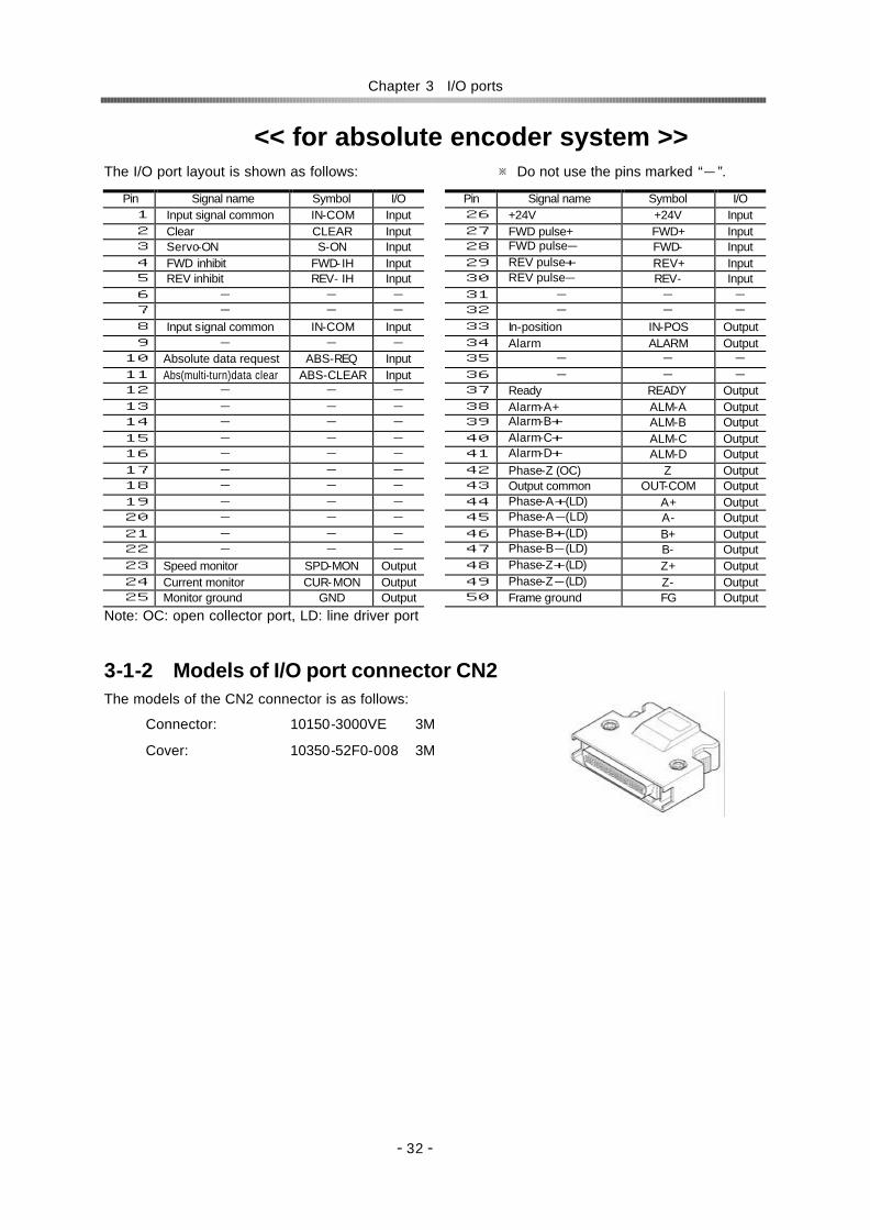
<<For absolute encoder system>>
Position mode Speed mode Pin Signal Symbol I/O Pin Signal Symbol I/O
1 Input signal common IN-COM Input 1 Input signal common INPUT-COM Input 2 Clear CLEAR Input 2 Clear CLEAR Input 3 Servo-ON S-ON Input 3 Servo-ON S-ON Input 4 FWD inhibit FWD- IH Input 4 FWD enable FWD-EN Input 5 REV inhibit REV- IH Input 5 REV enable REV-EN Input 6 - - - 6 Command change CMD-CHG Input 7 - - - 7 - - - 8 Input signal common IN-COM Input 8 Input signal common IN-COM Input 9 - - - 9 - - -
10 Absolute data request ABS-REQ Input 10 Absolute data request ABS-REQ Input 11 Abs(multi-turn)data clear ABS-CLEAR Input 11 Abs(multi-turn)data clear ABS-CLEAR Input 12 - - - 12 - - - 13 - - - 13 - - - 14 - - - 14 - - - 15 - - - 15 - - - 16 - - - 16 - - - 17 - - - 17 - - - 18 - - - 18 - - - 19 - - - 19 - - - 20 - - - 20 - - - 21 - - - 21 - - - 22 - - - 22 - - - 23 Speed monitor SPD-MON Output 23 Speed monitor SPD-MON Output 24 Current monitor CUR-MON Output 24 Current monitor CUR-MON Output 25 Monitor ground GND Output 25 Monitor ground GND Output 26 +24V +24V Input 26 - - - 27 FWD pulse+ FWD+ Input 27 - - - 28 FWD pulse- FWD- Input 28 - - - 29 REV pulse+ REV+ Input 29 - - - 30 REV pulse- REV- Input 30 - - - 31 - - - 31 Speed command SPD-CMD Input 32 - - - 32 Speed command ground SG-GND Input 33 In-position IN-POS Output 33 Attained speed HI-SPD Output 34 Alarm ALARM Output 34 Alarm ALARM Output 35 - - - 35 - - - 36 - - - 36 - - - 37 Ready READY Output 37 Ready READY Output 38 Alarm-A+ ALM-A Output 38 Alarm-A+ ALM-A Output 39 Alarm-B+ ALM-B Output 39 Alarm-B+ ALM-B Output 40 Alarm-C+ ALM-C Output 40 Alarm-C+ ALM-C Output 41 Alarm-D+ ALM-D Output 41 Alarm-D+ ALM-D Output 42 Phase-Z (OC) Z Output 42 Phase-Z (OC) Z Output 43 Output common OUT-COM Output 43 Output common OUT-COM Output 44 Phase-A+(LD) A+ Output 44 Phase-A+(LD) A+ Output 45 Phase-A-(LD) A- Output 45 Phase-A-(LD) A- Output 46 Phase-B+(LD) B+ Output 46 Phase-B+(LD) B+ Output 47 Phase-B-(LD) B- Output 47 Phase-B-(LD) B- Output 48 Phase-Z+(LD) Z+ Output 48 Phase-Z+(LD) Z+ Output 49 Phase-Z-(LD) Z- Output 49 Phase-Z-(LD) Z- Output 50 Frame ground FG Output
50 Frame ground FG Output
Note: OC: open collector port, LD: line driver port

Chapter 1 Outlines of the HA-655 driver
- 8 -
1-8 Operating display panel The HA-655 driver provides a 6-digit LED display and four operation keys on the front panel. The panel executes monitoring, tuning, setting, and JOG operation.
1-8-1 Outlines of operation modes The HA-655 driver provides the following four modes: monitoring, tuning, setting, and operations.
Monitor mode
The HA-655 driver displays position and speed commands, a current position from a motor-encoder, a pulse count in an error counter, states of input and output signals, load conditions, alarm histories, and a code number for the actuator for which the driver is set. The mode can be used for diagnosing an abnormal driver.
After power supply, the monitor mode starts up and works as the hub of other three modes for operation.
Tune mode
The tuning mode includes various parameters to control the actuator motion. Setting the most suitable value for each parameter obtains the optimum performance of the actuator.
Parameter mode
The parameter mode sets various parameter values relating to the fundamental operational functions such as: specifications of the position mode or the speed mode, configurations of input signals, an electronic gear function, limiting values of speed and torque, and parameters to communicate with a host.
Test mode
The test mode includes required functions for system tests; such as JOG operation functions, operations of pseudo output signals, I/O signal monitors, and so on.
1-8-2 Selecting a mode After powering the driver, the monitor mode starts up automatically. The [ADJ] and [SET] keys select a mode.
Powering
Monitor mode
Parameter mode Tune mode Test mode
ADJ
3 sec. 3 sec.
ADJ SET SET
3 sec.
SET

Chapter 1 Outlines of the HA-655 driver
- 9 -
1-8-3 Functions in modes Each mode individually provides the following functions of the position mode and the speed mode.
Mode Code Position mode Setting Code Speed mode Setting 0 Error counter state 0 Error counter state 1 Motor revolutions 1 Motor revolutions 2 ――― 2 Speed command voltage 3 Error pulse count (Low) 3 Error pulse count (Low) 4 Error pulse count (High) 4 Error pulse count (High) 5 Torque monitor 5 Torque monitor 6 Overload rate 6 Overload rate 7 Feedback pulse (Low) 7 Feedback pulse (Low) 8 Feedback pulse (High) 8 Feedback pulse (High) 9 Command pule (Low) 9 ――― A Command pulse (High) A ――― b Command pulse frequency b ――― c I/O monitor c I/O monitor d Alarm history d Alarm history E Actuator code E Actuator code
Mon
itor
mod
e
F ―――
Impossible
F ―――
Impossible
0 Speed loop gain 0 Speed loop gain 1 S-loop integral compensation 1 S-loop integral compensation 2 Position loop gain 2 Position loop gain
Possible
3 Feed-forward gain 3 ――― ――― 4 In-position range
Possible
4 ――― ――― 5 ――― ――― 5 Attained speed 6 ――― ――― 6 Internal speed command 7 ――― ――― 7 Acceleration time constant 8 ――― ――― 8 Deceleration time constant
Tun
e m
ode
9 ――― ――― 9 Speed command offset
Possible
0 Control mode 0 Control mode Possible 1 Command configuration 1 ――― ――― 2 Multiplication of 2-phase pulse 2 ――― ――― 3 Electronic gear - denominator 3 ――― ――― 4 Electronic gear - numerator 4 ――― ――― 5 Error count cleared by S-ON 5 ――― ――― 6 Position error allowance
Possible
6 ――― ――― 7 ――― ――― 7 Zero clamp 8 Rotary direction 8 Rotary direction 9 Speed conversion factor 9 Speed conversion factor A Speed limit A Speed limit b Torque limit b Torque limit c Alarm logic
Possible
c Alarm logic
Possible
d ――― ――― d ――― ――― E ――― ――― E ――― ―――
Par
amet
er m
ode
f ABS multi-turn data clear Impossible f ABS multi-turn data clear Impossible Jo JOG operation Possible Jo JOG operation Possible SP JOG speed SP JOG speed Ac JOG acceleration
Possible Ac JOG acceleration
Possible
InP Output port operation Possible InP Output port operation Possible c I/O monitor Impossible c I/O monitor Impossible
An Analog monitor manual output Possible An Analog monitor manual output Possible Test
mod
e
So Speed command auto-offset Possible So Speed command auto-offset Possible
Chapter 1 Outlines of the HA-655 driver
- 10 -
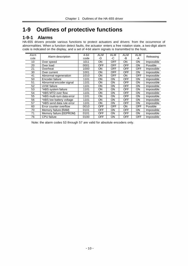
1-9 Outlines of protective functions 1-9-1 Alarms HA-655 drivers provide various functions to protect actuators and drivers from the occurrence of abnormalities. When a function detect faults, the actuator enters a free rotation state, a two-digit alarm code is indicated on the display, and a set of 4-bit alarm signals is transmitted to the host.
Alarm code Alarm description 4-bit
code ALM -D
ALM -C
ALM -B
ALM -A Releasing
10 Over speed 1011 ON OFF ON ON Impossible 20 Over load 0001 OFF OFF OFF ON Possible 21 Overheat 1000 ON OFF OFF OFF Impossible 30 Over current 1001 ON OFF OFF ON Impossible 41 Abnormal regeneration 1010 ON OFF ON OFF Impossible 50 Encoder failure 1101 ON ON OFF ON Impossible 51 Abnormal encoder signal 1101 ON ON OFF ON Impossible 52 UVW failure 1101 ON ON OFF ON Impossible 53 *ABS system failure 1101 ON ON OFF ON Impossible 54 *ABS MTD over flow 1101 ON ON OFF ON Impossible 55 *ABS multi-turn data error 1101 ON ON OFF ON Impossible 56 *ABS low battery voltage 1101 ON ON OFF ON Impossible 57 *ABS send data rule error 1101 ON ON OFF ON Impossible 60 Error counter overflow 0010 OFF OFF ON OFF Possible 70 Memory failure (RAM) 0101 OFF ON OFF ON Impossible 71 Memory failure (EEPROM) 0101 OFF ON OFF ON Impossible 76 CPU failure 0100 OFF ON OFF OFF Impossible
Note: the alarm codes 53 through 57 are valid for absolute encoders only.

Chapter 1 Outlines of the HA-655 driver
- 11 -
1-9-2 Protective functions
The HA-655 driver provides the following alarms to protect the servo system, and presents an alarm code on the preceding paragraph.
Over speed (10) If a motor exceeds its maximum speed or if motor rotates abnormally, the alarm occurs. To clear the alarm, shut off the control power once and turn it on again.
Over load (20)
The driver always monitors the motor current, and if the current exceeds the curve in the figure below, the overload alarm occurs.
For example:
(1) The alarm occurs if the current slightly exceeds 1.2 times of nominal current for a long duration.
(2) The alarm occurs if the current of three times of the nominal current flows for 20 seconds.
It is possible to clear the alarm by inputting signal to [CN2-2 clear: CLEAR].
Overheat (21)
The alarm occurs by activating the thermal switch of an IPM element in the HA-655 driver. To clear the alarm after troubleshooting, shut off the control power once and turn it on again.
Over current (30) The alarm occurs when the servo control element of the driver detects excessive current. To clear the alarm after troubleshooting, shut off the control power once and turn it on again.
Abnormal regeneration (41)
The alarm occurs by activating the thermal switch of the regeneration resistor in the HA-655 driver at 100. To clear the alarm after troubleshooting, shut off the control power once and turn it on again.
Encoder failure (50) The alarm occurs when the encoder signal ceases. To clear the alarm after troubleshooting, shut off the control power once and turn it on again.
The alarm also occurs when a built-in battery of the HA-655 driver for the absolute encoder is taken off in spite of normal conditions. To clear the alarm, shut off the control power once and turn it on again.
Nominal current
Max. current
Actuator current
1000
100
10
1.2 times of nominal current
Del
ay (
s)
×1 ×2 ×3
Over load range
Chapter 1 Outlines of the HA-655 driver
- 12 -
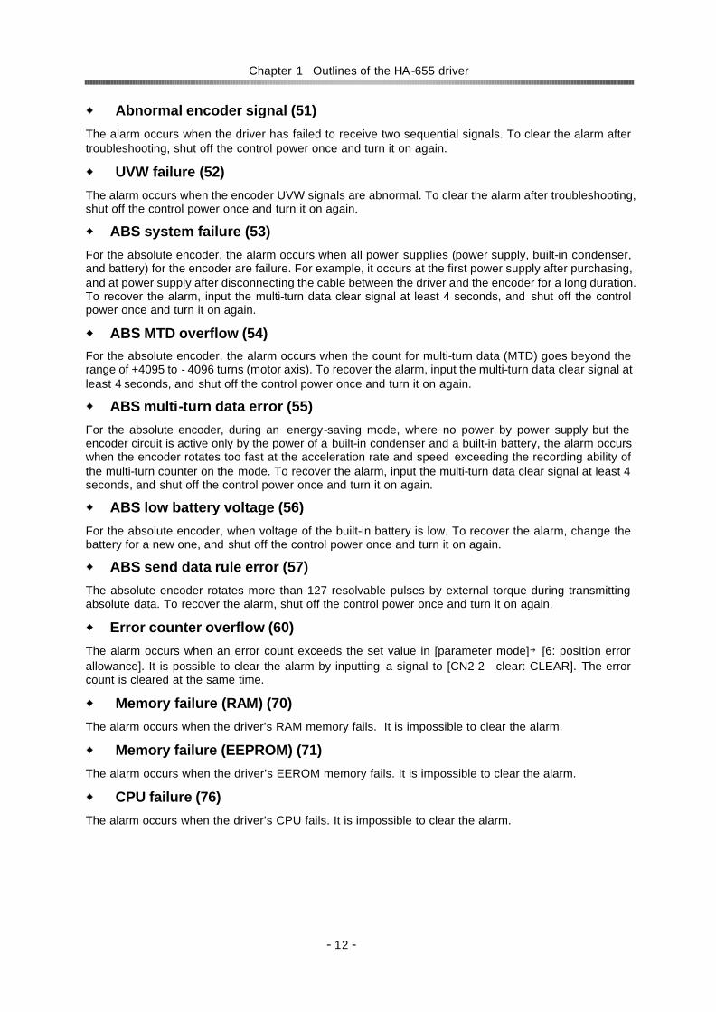
Abnormal encoder signal (51)
The alarm occurs when the driver has failed to receive two sequential signals. To clear the alarm after troubleshooting, shut off the control power once and turn it on again.
UVW failure (52)
The alarm occurs when the encoder UVW signals are abnormal. To clear the alarm after troubleshooting, shut off the control power once and turn it on again.
ABS system failure (53)
For the absolute encoder, the alarm occurs when all power supplies (power supply, built-in condenser, and battery) for the encoder are failure. For example, it occurs at the first power supply after purchasing, and at power supply after disconnecting the cable between the driver and the encoder for a long duration. To recover the alarm, input the multi-turn data clear signal at least 4 seconds, and shut off the control power once and turn it on again.
ABS MTD overflow (54) For the absolute encoder, the alarm occurs when the count for multi-turn data (MTD) goes beyond the range of +4095 to - 4096 turns (motor axis). To recover the alarm, input the multi-turn data clear signal at least 4 seconds, and shut off the control power once and turn it on again.
ABS multi-turn data error (55)
For the absolute encoder, during an energy-saving mode, where no power by power supply but the encoder circuit is active only by the power of a built-in condenser and a built-in battery, the alarm occurs when the encoder rotates too fast at the acceleration rate and speed exceeding the recording ability of the multi-turn counter on the mode. To recover the alarm, input the multi-turn data clear signal at least 4 seconds, and shut off the control power once and turn it on again.
ABS low battery voltage (56)
For the absolute encoder, when voltage of the built-in battery is low. To recover the alarm, change the battery for a new one, and shut off the control power once and turn it on again.
ABS send data rule error (57)
The absolute encoder rotates more than 127 resolvable pulses by external torque during transmitting absolute data. To recover the alarm, shut off the control power once and turn it on again.
Error counter overflow (60)
The alarm occurs when an error count exceeds the set value in [parameter mode]→[6: position error allowance]. It is possible to clear the alarm by inputting a signal to [CN2-2 clear: CLEAR]. The error count is cleared at the same time.
Memory failure (RAM) (70)
The alarm occurs when the driver’s RAM memory fails. It is impossible to clear the alarm.
Memory failure (EEPROM) (71)
The alarm occurs when the driver’s EEROM memory fails. It is impossible to clear the alarm.
CPU failure (76)
The alarm occurs when the driver’s CPU fails. It is impossible to clear the alarm.

Chapter 2 Functions
- 13 -
Chapter 2 Functions 2-1 Control system of the HA-655 driver It is said that [plan, do, see] is essential to perform perfect jobs. In other words, the [plan, do, see] is the repeating cycle of command→action→result→feedback→modified command → action → feedback → ・ ・ ・ ・ . Driving machines precisely requires the same control as the above job cycle, that is [Motion command→run→feedback→modified command→・・・・].
For example, assume the required motion is rotation to a target angle and stopping there. To perform the motion, the motor must be equipped with an angular sensor to detect a current position, and the position data must be compared with the command. If the position data is different than the command, the motor rotates until the position data becomes equal to the command. This is an example of a position servo system.
The speed control system is the same. The motor is equipped with a speed sensor and the speed is compared with the speed command. If the speed is different from the command, the motor accelerates or decelerates until the motor speed becomes equal to the command. This is an example of the speed servo system.
The HA-655 driver realizes above both controls of position and speed with the same unit.
The fundamental configuration of servo system of the HA-655 driver is as follows:
The HA-655 driver function is consists of three parts: the position control block, the speed control block, and the power amplifier.
In the position mode, a command position from a host is compared to a feedback position. If there is a difference between them, the position control block commands the power amplifier through the speed control block to flow current to the actuator until there is no difference.
In the speed mode, a speed command is directly inputted to the speed control block. The speed block compares the command and current feedback speed. If there is a difference between them, the speed control block commands to the power amplifier flow the current to the actuator until there is no difference.
The HA-655 driver allows two types of encoder as a functional member of the feedback system, optionally: an incremental encoder or an absolute encoder.
HA-655 driver
Position command
Position control block
Speed feedback
Actuator Speed
control block
Speed command
Position feedback
Driven machine
Encoder
Power amplifier
Plan Do See
Perfect job cycle
Feedback
Com. Run Result
Feedback
Precise motion control

Chapter 2 Functions
- 14 -
2-2 Position mode The HA-655 driver makes use of either the position control or the speed control. This section describes the position mode. (※ The default setting is the [position mode].)
Before driving, set the control mode by [parameter mode] → [0: control mode].
2-2-1 Command configuration in position mode In the position mode, the command is transmitted from a host in the form of a digital pulse signal train. The HA-655 driver provides two pair of two ports (CN2-27&28, CN2-29&30) for the command pulses. Signals of three type of configurations are available for the ports.
Setting a command configuration
[Parameter mode]→[1: command configuration]
Relating I/O pins
Input pins: CN2-26 to 30
(1) 2-pulse train (FWD and REV pulse train) Two pairs of two terminals are provided, and each of FWD and REV pulse trains is assigned a pair independently. FWD commands and REV commands are inputted in the pair of FWD ports and REV ports respectively, as shown in the figure below. When signals are inputted to a pair of terminals, the signal to the other should keep [OFF] state.
(2) 1-pulse train (polarity + pulse train) One pair of terminals is assigned dedicatedly for command pulse train, and the other is assigned to a sign for rotary direction. Position commands are inputted in the FWD port pair only and the REV port pair accepts the sign of rotary direction, as shown in the figure below. [OFF] or [Low level] state is for the FWD command and [ON] or [High] level is for the REV command.
REV command
Opt-isolator: OFF
FWD command
Opt-isolator: OFF FWD+FWD-
REV+REV-
110Ω
0Ω
27
28
110Ω
0Ω
29
30
REV command FWD command
Opt-isolator: OFF Opt-isolator: ON
FWD+FWD-
REV+REV-
110Ω
0Ω
27
28
110Ω
0Ω
29
30

Chapter 2 Functions
- 15 -
(3) 2-phase pulse train (A-B phase pulses with 90 degree difference) Both port pairs receive the command pulse trains that have a 90 electric degree difference relative to each other as shown in the figure below. For the FWD command, the pulse train to the FWD ports advances 90 degrees from the REV port train. For the REV command, the REV port train advances from the FWD port train.
The encoder pulse trains to the driver have this 2-phase pulse configuration.
Multiplication of command
When the command configuration is a [2-phase pulse] type, it is possible to multiply the command pulse train by 2 or 4 for the command pulse train to an actuator.
The encoder feedback pulse train is quadrupled.
Setting
[Parameter mode] → [2: multiplication of 2-phase pulse]
Electronic gear
The electronic gear function can be set make a given displacement of the driven mechanism for one command pulse, an integer, or a convenient number. For example, it is convenient to set the displacement of 0.1 micrometer for one pulse as shown in figure to the right.
The function multiples the command pulse count by the coefficient (fraction).
The relation of [denominator / numerator] of the coefficient is obtained as follows:
Rotary motion:
Linear motion:
With above formulas, each denominator and numerator should be set an integer between 1 and 50.
Setting
[Parameter mode]→[3: electronic gear-denominator], and [4:electronic gear-numerator]
FWD
REV
1 Input
Double
Quadruplicated
2 3 4
1
1
2 3 4 5 6 7 8
2 3 5 4 6 7 8 9 10 11 12 13 14 15 16
numerator-rdenominato-
gearElectronicgearElectronic
3604resolutionActuator
loadofratioductionRepulseperAngle ××=
FHA-C
W
1 P 0.1μm
4resolutionActuatormechanismdrivenofpitchFeed
pulseperntDisplaceme ××=numerator-
rdenominato-gearElectronic
gearElectronic
90°differ
REV command FWD command
90°differ
FWD+FWD-
REV+REV-
110Ω
0Ω
27
28
110Ω
0Ω
29
30

Chapter 2 Functions
- 16 -
2-2-2 Command transmitting system Two systems are provided for transmitting command pulses: [open collector] and [line driver].
Open collector system
This system employs a transistor whose emitter is common and whose collector is open. Since the output signal is voltage type, this system is unsuitable for long distance transmission due to line voltage drop.
Line driver system
The line driver system conforms to (EIA) RS-422 standard providing line drivers for transmitting signal pulses. Since the output signal is current type, this system is suitable for long distance transmissions without attenuation of signals.
Furthermore, the line driver system transmits data faster than the open collector system.
2-2-3 Outputting encoder signals Two kinds of encoder are selectable for the FHA-C series actuator: incremental or absolute. The incremental encoder feeds back two pulse-trains into the HA-655 driver as shown in the figure to the right. The pulse trains are called [phase-A] and [phase-B]. For the encoder resolution, refer to actuator’s technical manual.
On the other hand, the absolute encoder feeds back a combination of absolute signals and two pulse-train signals.
In addition to the 2-phase pulse trains, both encoders output a [phase-Z] pulse signal once per motor rotation for use as an origin. The pulse signal is sometimes called [phase-C] or [index].
The HA-655 driver outputs encoder signals using a line driver system. The signals can be received by a line receiver: AM26LS32 (EIA -422A) or equivalent. Phase-Z signal is also available (open collector output CN-42 pin).
The phase-Z signal is asynchronous.
Three encoder signals mentioned above are available for a host.
Relating I/O pins
Output pins: CN2-42 to 49
Input
Transmission line Line driver
Use twist pair cable.
Output
Phase-A
Phase-B
Phase-Z
Forward
Phase-A
Phase-B
Phase-Z
Reverse
Emitter
Input
Transmission line Collector
Use twist pair cable.
Output

Chapter 2 Functions
- 17 -
2-2-4 Absolute encoder signals u General descriptions and functions of absolute encoders
The absolute encoder housed in a FHA-C series actuator provides an absolute sensor to generate an absolute pulse train for a resolvable position (the sensor is herein after referred to as “single-turn encoder”.), and an electronic counter to generate an absolute pulse train for a revolution of the motor (the counter is hereinafter referred to as “multi-turn counter”.).
An absolute position of the encoder is kept in the memory, which is always energized by a combination of the built-in condenser in the actuator and the backup battery housed in the HA-655 driver.
Please interpret that “single-turn” and “multi-turn” in the manual mean one and plural revolutions of the encoder (the motor) in an actuator, respectively. Therefore, the actual actuator resolvable position of either “single-turn” or “multi-turn” can be obtained by multiplying an absolute pulse train of the single-turn encoder and the multi-turn counter by a reduction ratio of the actuator.
u Single-turn absolute encoder
The single-turn encoder is composed of an encoder disk, an LED light source, and a photo-detector. The single-turn absolute encoder system outputs a current absolute pulse train combined with an absolute pulse train of the multi-turn counter in response to the [ABS data request] signal. The resolution of the encoder is 8192 positions per turn (13 bits). To obtain actual resolvable position of the actuator, the absolute pulse train should be multiplied by the reduction ratio of the actuator.
u Multi-turn counter
The multi-turn counter outputs a current absolute pulse train combined with an absolute pulse train of the single-turn absolute encoder system in response to the [ABS data request] signal. The allowed range of the counter is from +4095 to –4096. To obtain an actual resolvable position of the actuator, the absolute pulse train should be multiplied by the reduction ratio of the actuator.
u Energy-saving mode In the energy-saving mode, even during no power supply for the HA-655 driver, the multi-turn counter keeps a count in its memory only by the power of a built-in condenser and a built-in battery.
u Allowable encoder (motor) speed in energy-saving mode
The limit of an encoder (a motor) speed is 5,000r/min. The [alarm 55: ABS multi-turn data error] occurs i f the encoder rotates at more than the limited speed, and a correct absolute pulse train of the multi-turn counter may not obtained. Moreover, there are additional limits during motor acceleration duration as shown the figure below.
Allowable speed range
Error detectable range (abnormal data)
Error undetectable range (abnormal data)
5000rad/s2
16000rad/s2
Response time (ms)
Enc
oder
spe
ed(r
/min
)

Chapter 2 Functions
- 18 -
u Notice at power on
If power is turned on while the motor rotates at 2800r/min or more, the [Alarm 55] may occur. In spite of the alarm, the multi-turn counter works normal.
u ABS (multi -turn) data clear signal (CN2-11: ABS-CLEAR)
The ABS (multi-turn) data clear signal should be inputted at:
(a) the initial power supply, and;
(b) wasting about 30 minutes or more for exchanging the built-in battery.
At either case, the multi-turn counter does not keep any data. To recover from the problem, move the actuator to a proper origin and input the [ABS (multi-turn) data clear signal] at least four seconds to clear the multi-turn counter to zero. However, the single-turn encoder keeps its resolvable position during above-mentioned operation firmly.
During exchanging the battery, the built-in condenser helps the multi-turn counter to keep its count at least about 30 minutes with charged energy in the condenser. Therefore, the operation of inputting [ABS (multi-turn) data clear signal] is not required before discharging the energy.
Though the [alarm 50: encoder failure] may occur at power ON operation after exchanging the battery, the encoder system is normal. To recover the problem, shut off the power once and turn it on again.
u Acquisition of absolute pulse trains generated by absolute encoder system
The HA-655 driver provides two selectable acquisition methods of absolute pulse trains generated by the absolute encoder system; from I/O ports and from CN3 port (RS-232C). (a) Acquisition from I/O ports (CN2-44, -45 and CN2-46, -47)
Acquiring an absolute pulse train
An absolute pulse train of an absolute encoder system is a combination of an absolute code (13 bits) of the multi-turn counter expressing an encoder’s revolution number from its origin, and an absolute code (13 bits) of the single-turn encoder expressing a resolvable position of the encoder (the motor). Incremental signal trains following to the absolute pulse train of an absolute encoder system may be used for monitoring signals of operating condition of the motor.
As a rule, acquiring an absolute pulse train is possible only one time during power ON procedure illustrated below. If acquiring an absolute pulse train is required at another timing, use the CN3 port for acquiring while the motor is stopping.
84µs
0ms(min.)
4s(max.)
3ms(max.)
0ms(min.) 10ms(max.)
Servo-ON available
90ms(max.)
840µs
90ms(max.)
Note4
Multi-turn word Single-turn word Note2 Incremental signal train Note1 Note1
Control power OFF to ON
Main power OFF to ON
Ready OUT
Alarm OUT
Absolute data request IN
Phase-Z OUT
Phase-A, -B OUT
Servo-ON IN

Chapter 2 Functions
- 19 -
Note 1: Both output signals of phase-A and phase-B are settled at LOW-level. To settle at LOW-level, at least three pulses are outputted. Make a sequence for the host device ignoring outputted pulses while the phase-Z is LOW-level before generating an absolute pulse train, and during other LOW-level duration of the phase-Z signal.
Note 2: An absolute pulse train for single-turn encoder is outputted after around 1 ms of outputting phase-Z signal.
Note 3: The servo-ON signal is unaccepted until completing the transmission of a set of absolute pulse trains by the [absolute data request] signal.
Note 4: The [alarm 57] occurs if the single-turn encoder rotates more than 127 resolvable position while the multi-turn counter is transmitting an absolute pulse train.
Acquiring multi-turn count
For FWD revolution of the encoder (motor), the phase-A signal has 90 degree phase shift against phase-B signal, and for REV revolution the phase-A signal has 90 degree phase delay against phase-B signal as shown below.
Increasing or decreasing the multi-turn counter of the host device should be discriminated by the phase shift or delay of phase-A against phase-B. Acquire the signal at rising edge of the signal.
Acquiring single-turn encoder and incremental pulse trains
For FWD revolution of the encoder (motor), the phase-A signal has 90 degree phase shift against phase-B signal, and for REV revolution the phase-A signal has 90 degree phase delay against phase-B signal as shown below.
Increasing or decreasing the single-turn encoder counter of the host device should be discriminated by the phase shift or delay of phase-A against phase-B. Acquire the signal at rising and falling edge of the signal.
Phase-A
Count 0 +1 +2 +3 0 -1 -2 -3
FWD revolution
Phase-B
REV revolution
Phase-A
Phase-B
FWD revolution REV revolution
Count 0 +1z
+2z
+3z
+4z
0 -1 -2 -3 -4

Chapter 2 Functions
- 20 -
An example of signal transmission
The following is an example of the multi-turn count: 8, single-turn encoder count: 25 and an incremental pulse train at a usual operation.
The actual resolvable position of the encoder (motor) can obtained by the calculation of:
multi-turn count x 8192 + single turn encoder count
(b) Acquiring from CN3 port (RS -232C)
Connecter specifications
Connect an RS-232C cable having following specifications between the CN3 port of the HA-655 driver and a RS-232C port of a host device.
Connecters: D-sub connecter having 9 female pins
Pin assignments:
Communication format (RS-232C port setting)
Baud rate: 19200 bps
Data bits: 8 bit
Stop bits: 1 bit
Parity: None
Communication protocol
Sending a command to HA-655 driver (host →HA-655)
The command should be 10 characters in length including a delimiter as illustrated below. The HA-655 driver waits until receiving 10 characters without any processing. Make sure that the message has 10 characters including a delimiter.
Phase-Z
90 ms (max.) 90 ms (max.)
Multi-turn count: +8 Single-turn count: +25 Incremental pulse train
Phase-A
Phase-B
1 2 3 4 5 6 7 8 9
1 2 3 4 5 6 7 8 9
RXD TXD DTR GND DSR NC NC
Driver side Host side
XXX+ YYYYY Cr(delimiter: 0Dh)
Motion command (4 characters)
Additional data (5 characters with a sign)
Attach on the last of command (1 character)
Note: “0” means zero.

Chapter 2 Functions
- 21 -
Receiving a message from HA-655 driver (HA-655 →host)
In case of requiring for data:
Data & 0Dh
then ;
q 0Dh
In case of not requiring for any data:
q 0Dh
When processing for a command from the host is finished and the HA-655 driver can accept a next command, the HA-655 driver responds to the host with “q 0dh” as described above. Then the HA-655 driver can accept the next command.
In spite of this, the HA-655 responds other codes as follows:
- servo ON condition (the motor is energized): no processing and acknowledgement is “s 0Dh”;
- abnormal command form the host: acknowledgement is “x 0Dh”.
Absolute Data request Command from the host: DGR+ 00000 0Dh
Response from HA-655: XX・・・XX 0Dh (Note: XX・・・XX means a numerical data.)
q 0Dh
The absolute resolvable position is the data calculated by the formula of:
Multi-turn count x 8192 + single turn count
If the position is negative (from an origin), the sign “-” is attached at the first position of the data, if it is positive, no sign is attached. The data is expressed in the ASCII decimal codes.
The host device can acknowledge data termination with the code “q 0Dh”.
Note: The servo-ON signal is unaccepted until completing the transmission of a set of absolute pulse trains by the [absolute data request] signal.
Multi-turn data clear
Command from the host: OWW+ 00000 0Dh
Response from HA-655: q 0Dh for normal data clearing
x 0Dh for abnormal data clearing
If the data clearing process completes normally, the code “q 0Dh” may be acknowledged to the host after about 5 seconds from commanding.
If the process terminates abnormally, HA-655 driver acknowledges the code “x 0Dh” to the host, and quits the multi-turn data clearing process.
The abnormal termination may occur at cases as follows:
- servo ON condition (the motor is energized);
- the actuator equips an incremental encoder;
- the second multi-data commanding before receiving the acknowledgement for the first command (duplicated commands).
By the multi-turn data clearing, a discrepancy between the resolvable position count in the memory of HA-655 driver and the actual resolvable position count of the encoder comes into existence. To synchronize them, shut off the control power once and turn it on again, or send a reset command described below.
Note: “0” means zero.
Note: “0” means zero.
Note: “0” means zero.
Note: “0” means zero.
Note: “0” means zero.
Note: “0” means zero.

Chapter 2 Functions
- 22 -
The reset command should be sent after 300 milliseconds or more from receiving the code “q 0Dh”, otherwise the [alarm 51: Abnormal encoder signal] may occur.
Reset
Command from the host: ORW+ 00000 0Dh
Response from HA-655: q 0Dh for normal resetting
x 0Dh for abnormal resetting
u Back-up system for absolute data
For protecting the absolute memory against volatilizing while control power is OFF, the absolute encoder system housed in the FHA-C actuator equips a condenser, and the HA-655 driver provides a battery.
Condenser:
Valid duration: about half hour after control power OFF (conditions: charged at least 3 hours, at ambient temperature: 25 degree C, no rotation)
Battery:
Lifetime: about one year after control power OFF (conditions: at ambient temperature: 25 degree C, no rotation) actual lifetime depends on servicing conditions.
Specifications: lithium battery model: ER17/33 (3.6V 1600mAh) manufactured by Hitachi Maxell co., Ltd. Harmonic Drive Systems Inc. is possible to supply the batteries on request.
Exchanging procedures:
When [alarm 56: battery low voltage] occurs, exchange to new battery by the following procedure:
(1) Shat off all power supply for the HA-655 driver.
(2) Detach a cover of battery case on the front panel of the HA -655 driver.
(3) Pull out the battery from the case by pulling both end of a ribbon.
Note: “0” means zero.

Chapter 2 Functions
- 23 -
(4) Disconnect the leads of the battery from the junction connecter.
(5) Connect the leads of the new battery to the junction connecter.
(6) Cram the battery with the leads and the connecter into the case.
(7) Attach a cover of battery case on the front panel of the HA -655 driver.
(8) If [alarm 50: encoder failure] occurs at power ON operation after exchanging the battery, the encoder system is normal. To recover the problem, shut off the power once and turn it on again.
(9) If [alarm 53: ABS system failure] occurs, the multi-turn counter does not keep any data. To recover from the problem, move the actuator to a proper origin and input the [ABS (multi-turn) data clear signal] for four seconds or more to clear the multi-turn counter to zero. However, the single-turn encoder keeps the absolute pulse train output during above-mentioned operation firmly.
Note: During exchanging the battery, the built-in condenser helps the multi-turn counter to keep its data for about 30 minutes or more with charged power in the condenser. Therefore, the operation of inputting [ABS (multi-turn) data clear signal] is not required in the case.

Chapter 2 Functions
- 24 -
2-2-4 Tuning Servo gains The HA-655 driver is fed back position and speed signals in the position mode as follows:
In the figure, the closed loop of [speed control block]→[power amplifier]→[actuator]→[encoder]→[speed control block] is called a [speed loop].
In the same manner, the closed loop of [position control block]→[speed control block]→[power amplifier]→[actuator]→[encoder]→[position control block] is called a [position loop].
The details of the loops are explained as follows:
[Position control block] and [position loop gain]
(1) The first function of the [position control block] is the [error count] calculation by the [error counter] in the block subtracting a feedback count from a command count.
(2) The second function is the block that converts the [error count] to a [speed command] multiplying a factor, and then transmits the [speed command] to the [speed control block]. The factor (Kp) is called [position loop gain].
It is clear in the formula that a large [error pulse] is converted into a high [speed command] and a zero pulse into a zero speed command, in other words, a stop command.
(3) If the [position loop gain (Kp)] is high, a small [error count] is converted into a higher [speed command]. That is to say, higher gain provides the servo system with better response.
However, very high gain commands result in high [speed commands] from very minimal [error count] which will result in overshooting. To compensate for the overshoot the [position control block] generates a high speed reverse command, then overshoots in the opposite direction * * * finally hunting motion may take place.
Conversely, if the [position loop gain (Kp)] is very low, you will get very slow positioning motion (undershoot), and a poor servo response.
(4) In conclusion, it is important to set the optimum value to the [position loop gain (Kp)]. The HA -655 driver has been set with the most suitable value for general applications as a factory default. If the load inertia is very heavy and the default is not suitable, tune it carefully.
Tuning method
[Tune mode]→[2: position loop gain]
HA-655 driver
Position command
Position control block
Speed feedback
Actuator Speed
control block
Position feedback
Driven mechanism
Encoder
Power amplifier
Speed loop
Position loop
countErrorKp ×V=

Chapter 2 Functions
- 25 -
[Speed control block], [speed loop gain], and [speed loop integral compensation]
(1) The first function of the [speed control block] is to subtract a feedback signal from a command signal.
(2) The second function is the block converts the difference to a [current command] multiplies it by a factor, and then transmits the [current command (I)] to the [power amplifier]. The factor (Kv) is called [speed loop gain].
It is clear in the formula that a significant [speed difference] is converted into a high [current command] and zero difference into zero current command, in other words, a stop command.
(3) Just as with the [position loop gain], higher gain provides better response and excessive gain results in hunting. Low gain requires no hunting but raises the occurrence of undershoots.
(4) The [speed loop integral compensation (Tv)] of The HA -655 driver makes less influence on load fluctuation. If the [speed loop integral compensation (Tv)] is smaller, the speed response to the load fluctuation becomes better, but too small a value results in hunting. Excessive compensation requires no hunting, but will result in a poor response for load fluctuation.
Tuning method
[Tune mode]→[0.speed loop gain], and [1: speed loop integral compensation]
Feed forward gain
(1) In the position mode The HA-655 driver controls the error count, (the difference between [command pulse] and [feedback pulse]), to be [0]. At the beginning of inputting a command pulse train, the actuator starts slowly because of small error count.
(2) The [feed forward] function may accelerate the actuator as much as possible, adding speed pulses converted from the command pulse frequency directly to the driver’s speed control loop.
(3) The relation between the feed forward and actuator motion is as follows:
Higher feeding allows for better following to command, but excessive feeding results in hunting and erratic motion.
Low feeding requires no hunting but a poor following of the command.
Tuning method
[Tune mode]→[3:Feed forward]
differencespeed11 ×
+×
STvKvI=
differencespeed×KvI=
HA-655 driver Speed command = Kp x Error pulse +speed pulse x Feed forward gain
Position command
Speed feedback
Actuator Speed
control block
Position feedback
Load mechanism
Encoder
Power amplifier
Feed forward Differential
Position control block

Chapter 2 Functions
- 26 -
2-2-5 FWD inhibit and REV inhibit The HA-655 driver provides [FWD inhibit] and [REV inhibit] input signal ports.
[FWD inhibit]: opening (OFF) the input inhibits forward rotation.
[REV inhibit]: opening (OFF) the input inhibits reverse rotation.
Opening (OFF) both inputs inhibits all rotation.
The inputs may be used to limit the motion range between limit sensors.
Connection
Refer to [CN2-1: input signal common], [CN2-4: FWD inhibit], and [CN2-5: REV common].
2-2-6 In-position In the position mode, even though the driver controls the actuator to make the [error count 0], it is not always possible due to the influence of external forces, acceleration, and deceleration. Establishing a positioning allowance is a good solution to the problem; that is [in-position range].
[Tune mode]→[4: in-position range] sets the allowance. The actuator position comes within the range calculated with the formula below, the [CN2-33: in-position] signal outputted.
Relating I/O signal pin
Output pin: CN2-33
Tuning method
[Tune mode]→[4: In-position range]
FWD inhibit REV inhibit
Motion range
rangepositionInpositionCommandpositionActuator −±≤

Chapter 2 Functions
- 27 -
2-3 Speed mode The HA-655 driver makes use of either the position control or the speed control. This section describes the speed mode. (※ The default setting is the [position mode].
Before running, set the control mode by [parameter mode] → [0: control mode].
2-3-1 Speed conversion factor In the speed mode, the command is sent from a host with an analog voltage signal. The [speed conversion factor] converts the [speed command] voltage to motor speed.
The [speed conversion factor] is the motor speed when the [speed command voltage] is [10V]. The actual motor speed is obtained by the following formula:
The [speed monitor] (SPD-MON: CN2-23pin) output voltage as follows:
Setting
[Parameter mode]→[9: speed conversion factor]
2-3-2 Voltage of speed command Input the voltage converted by the [speed conversion factor] into [CN2-31: speed command] and [CN2-32: speed command common] pins. The [speed command voltage] is obtained by [parameter mode]→[9: speed conversion factor].
FWD enable and REV enable
The HA-655 driver provides [FWD enable] and [REV enable] input ports. The rotary direction of the actuator is decided by the polarity of [CN2-31: speed command SPD-CMD] and ON/OFF states of [FWD enable] and [REV enable] as shown in the table below:
CN2-31 Speed cmd.: SPD-CMD +Command -Command
CN2-4 FWD enable: FWD-EN ON OFF ON OFF ON Zero clamp, zero speed REV rotation Zero clamp, zero speed FWD rotation CN2-5 REV enable:
REV-EN OFF FWD rotation Zero clamp, zero speed REV rotation Zero clamp, zero speed
Relating input pins
CN2-31: speed command, CN2-32: speed command common, CN2-4: FWD enable,CN2-5:REV enable
Speed command offset
In the speed mode, the motor may rotate slightly in spite of a [0V] speed command voltage. This problem may occur when the speed command voltage has an offset of a few milli-volts. This function removes the slight rotation compensating the command voltage offset. While inputting a [OV] command voltage adjust the speed command offset until the actuator stops rotating.
[Speed command automatic offset] function is also provided.
Setting
[Tune mode]→[9: speed command offset], [test mode]→[So: Speed command automatic offset]
10.0VfactorconversionSpeed
voltageCommandspeedMotor ×=
factorconversionSpeedspeedMotorvoltagemonitorSpeed
10.0V×=
factorconversionSpeedspeedMotorvoltagecommandSpeed 10.0V×=

Chapter 2 Functions
- 28 -
2-3-3 Tuning servo gains The HA-655 driver is fed back position and speed signals in the speed mode as follows:
In the figure, the closed loop of [speed control block]→[power amplifier]→[actuator]→[encoder]→[speed control block] is called [speed loop].
The details of the loop are described as follows:
[Speed control block], [speed loop gain], and [speed loop integral compensation]
(1) The first function of the [speed control block] is to subtract a feedback signal from a command signal.
(2) The second function is when the block converts the difference to a [current command] multiplies it by a factor, and then transmits the [current command] to the [power amplifier]. The factor (Kv) is called [speed loop gain].
It is clear in the formula that a [speed difference] is converted into a high [current command], and a zero difference into a zero current command, in other words, a stop command.
(3) If the [speed loop gain (Kv)] is high, a small [speed command] is converted into a higher [current command]. That is to say, higher gain provides the servo system with a better response.
However, very high gain settings can cause a very high [current command] in response to a small [speed command] which will result in overshooting. To compensate overshooting, the [speed control block] generates a high speed reverse command, then ・・・・・・・・・finally hunting motion may take place.
(4) Conversely, if the [speed loop gain (Kv)] is very low, you will get very slow positioning motion (undershoot) and poor servo response.
(5) The [speed loop integral compensation (Tv)] of the HA-655 driver minimizes the influence of load fluctuation. If the [speed loop integral compensation (Tv)] is low, the speed response to the load fluctuation becomes better, but very small value can result in hunting. Excessive compensation requires no hunting but a poor response for load fluctuation.
Setting
[Tune mode]→[0: speed loop gain], [1: speed loop integral compensation]
HA-655 driver
Speed control block
Speed command
Position control block
Speed feedback
Actuator
Position feedback
Driven mechanism
Encoder
Power amplifier
Speed loop
differencespeed×KvI=
differencespeed11 ×
+×
STvKvI=

Chapter 2 Functions
- 29 -
2-3-4 Command change The function can operate the actuator without command at the speed specified by [tune mode]→[6: internal speed command]. This is convenient for diagnosis and for test operation without hosts.
The actuator will rotate at the speed set by the [internal speed command] when a signal is input to CMD-CHG (CN2-6) and stops when the signal is removed.
Relating I/O pin
Input pin: CN2-6
2-3-5 Acceleration / deceleration time constants [Acceleration time constant] is the time it takes to accelerate the motor from [0 r/min] to the speed of [A: speed limit] of [parameter mode].
[Deceleration time constant] is the time it takes to decelerate the motor from the speed of [A: speed limit] of [parameter mode] to [0 r/min]. The deceleration time to speed command voltage is as follows: 2-3-6 Zero clamp In the speed mode when [speed command] is [0], the actuator may rotate slightly by force from the driven mechanism. The [Zero clamp] function forcefully stops the actuator when the speed command is [0].
Setting
[Parameter mode]→[7: zero clamp]
10factorconversionSpeed
itlimSpeedvoltageCommand
.consttime.Decel/Acceltime.Decel/Accel ××=
Take cares that the servo-lock function does not work and the actuator is free to rotate when:
- main and/or control power are not supplied;. - servo-ON signal is not inputted; - an alarm occurs. CAUTION

Chapter 2 Functions
- 30 -
2-4 Other functions 2-4-1 Indicating of pulse counts As shown in the figure to the right, the motion command pulses are transmitted to the HA-655 driver from a host. The driver drives the actuator corresponding to the motion command. When the actuator starts, the position pulses are sensed by the encoder and are fed back to the driver. The HA-655 driver continues to drive the actuator until the error count (difference between command count and feedback count) comes to zero.
In the monitor mode, [command pulse], [feedback pulse], and [error pulse] can be monitored. This function may be effective for diagnosis.
Indications
[Tune mode]→[3,4: error counter status], [7,8: feedback pulse], [9,A: command pulse]
2-4-2 Manual JOG operation It is possible to operate the actuator manually for test, for tuning, and for diagnosis without commands from a host. Pressing the [UP] and [DOWN] keys on the front panel rotates the actuator at pre-set speed and at pre-set acceleration.
Operation and setting
[Test mode]→[Jo: JOG operation], [SP: JOG speed], [Ac: JOG acceleration]
2-4-3 Monitoring inputs and operating outputs It is possible to monitor input ports of [clear], [servo -ON], [FWD inhibit] and [REV inhibit] for test, for tuning, and for diagnosis.
It is also possible to manually output signals of [in-position], [attained speed], [alarm] and so on without relations to the actuator state by pressing the [UP] and [DOWN] keys on the front panel outputs signals.
Operation and setting
[Test mode]→[b:I/O monitor], [InP:Output port operation]
Command pulse
Error counter
Position speed
control block
Feedback pulse

Chapter 3 I/O ports
- 31 -
Chapter 3 I/O ports Through the CN2 connector (50 pins; half pitch) the HA-655 driver communicates with a host. Details of the I/O ports are described in this chapter.
As the functions of the pins of the connector differ in each control mode, the functions are described separately by modes.
3-1 Position mode 3-1-1 I/O port layout
<< for incremental encoder system>> The I/O port layout is shown as follows: ※ Do not use the pins marked “-”.
Pin Signal name Symbol I/O Pin Signal name Symbol I/O 1 Input signal common IN-COM Input 26 +24V +24V Input
2 Clear CLEAR Input 27 FWD pulse+ FWD+ Input
3 Servo-ON S-ON Input 28 FWD pulse- FWD- Input
4 FWD inhibit FWD- IH Input 29 REV pulse+ REV+ Input
5 REV inhibit REV- IH Input 30 REV pulse- REV- Input
6 - - - 31 - - -
7 - - - 32 - - -
8 Input signal common IN-COM Input 33 In-position IN-POS Output
9 - - - 34 Alarm ALARM Output
10 - - - 35 - - -
11 - - - 36 - - -
12 - - - 37 - - -
13 - - - 38 Alarm-A+ ALM-A Output
14 - - - 39 Alarm-B+ ALM-B Output
15 - - - 40 Alarm-C+ ALM-C Output
16 - - - 41 Alarm-D+ ALM-D Output
17 - - - 42 Phase-Z (OC) Z Output
18 - - - 43 Output common OUT-COM Output
19 - - - 44 Phase-A+(LD) A+ Output
20 - - - 45 Phase-A-(LD) A- Output
21 - - - 46 Phase-B+(LD) B+ Output
22 - - - 47 Phase-B-(LD) B- Output
23 Speed monitor SPD-MON Output 48 Phase-Z+(LD) Z+ Output
24 Current monitor CUR-MON Output
49 Phase-Z-(LD) Z- Output
25 Monitor ground GND Output 50 Frame ground FG Output
Note: OC: open collector port, LD: line driver port
Chapter 3 I/O ports
- 32 -
<< for absolute encoder system >> The I/O port layout is shown as follows: ※ Do not use the pins marked “-”.
Pin Signal name Symbol I/O Pin Signal name Symbol I/O 1 Input signal common IN-COM Input 26 +24V +24V Input 2 Clear CLEAR Input 27 FWD pulse+ FWD+ Input 3 Servo-ON S-ON Input 28 FWD pulse- FWD- Input 4 FWD inhibit FWD- IH Input 29 REV pulse+ REV+ Input 5 REV inhibit REV- IH Input 30 REV pulse- REV- Input 6 - - - 31 - - - 7 - - - 32 - - - 8 Input signal common IN-COM Input 33 In-position IN-POS Output 9 - - - 34 Alarm ALARM Output
10 Absolute data request ABS-REQ Input 35 - - - 11 Abs(multi-turn)data clear ABS-CLEAR Input 36 - - - 12 - - - 37 Ready READY Output 13 - - - 38 Alarm-A+ ALM-A Output 14 - - - 39 Alarm-B+ ALM-B Output 15 - - - 40 Alarm-C+ ALM-C Output 16 - - - 41 Alarm-D+ ALM-D Output 17 - - - 42 Phase-Z (OC) Z Output 18 - - - 43 Output common OUT-COM Output 19 - - - 44 Phase-A+(LD) A+ Output 20 - - - 45 Phase-A-(LD) A- Output 21 - - - 46 Phase-B+(LD) B+ Output 22 - - - 47 Phase-B-(LD) B- Output 23 Speed monitor SPD-MON Output 48 Phase-Z+(LD) Z+ Output 24 Current monitor CUR-MON Output
49 Phase-Z-(LD) Z- Output 25 Monitor ground GND Output 50 Frame ground FG Output
Note: OC: open collector port, LD: line driver port
3-1-2 Models of I/O port connector CN2 The models of the CN2 connector is as follows:
Connector: 10150-3000VE 3M
Cover: 10350-52F0-008 3M

Chapter 3 I/O ports
- 33 -
3-1-3 I/O port connections in the position mode This section describes the connection between the I/O ports and a host in the position mode.
Inputs: The HA-655 driver provides six ports for inputs as shown in the figure to the right.
Specifications Voltage: DC24V±10% Current: 20mA or less (for each port)
An input port circuit is shown in the figure to the right. The ports marked with (*) are available for absolute encoder system only.
Connection
The HA-655 driver does not provide the power supply for input signals. Connect a [+24V] power supply for the signals to [CN2-1: input signal common].
Outputs: The HA-655 driver provides eight ports for outputs as shown in the figure to the right.
Specifications Port: Open collector Voltage: DC24V or less Current: 40mA or less (for each port)
All ports are insulated by opto-isolators.
An output port circuit is shown in the figure to the right.
Connection
Connect output signals between their respective output ports and [CN2-43: output common] port.
IN-
2.2k
10k
Voltage DC24V±10%Current 20mA or less (for each port)
HA-655
DC24V
0V
External power supply 0.01μF
CN2-33 etcRy
CN2-43OUT-COM
Externalpower
CLEAR
Servo-ON
FWD inhibit
REV inhibit
* ABS data request
* ABS (multi0turn) data clear
In-position
Alarm
Alarm codes
Phase-Z
Output common
Ready

Chapter 3 I/O ports
- 34 -
3-1-4 I/O port functions in the position mode
This section describes I/O port functions in the position mode.
CN2-1 Input signal common: IN-COM (input)
Function
This is the common port for inputs: [CN2-2, -3, -4, -5, -10, -11]. Supply external power for inputs to this the port.
Connection
Connect [+24V] external power supply for inputs here.
CN2-2 Clear: CLEAR (input)
Function
(1) If alarm exists:
This clears the alarm state, returns to operable state, and clears the error count to [0]. For alarms that cannot be cleared, shut off the control power once, and turn it on again.
(2) If no alarm exists:
This clears the error count to [0]. At the same time, this clears the command count and the feedback count.
Connection
Connect [NO-contact signal (a-contact)]. Refer to [CN2-1: input signal common].
CN2-3 Servo-ON: S-ON (input)
Function
This turns the servo power for the HA-655 driver ON and OFF.
When the input is ON, the servo power of the HA -655 driver is ON and the actuator can be driven. When OFF, the servo power turns OFF and the motor is free to rotate.
Connection
Connect [NO-contact signal (a-contact)]. Refer to [CN2-1: input signal common].
CN2-4 FWD inhibit: FWD-IH (input)
CN2-5 REV inhibit: REV-IH (input)
Function
[FWD inhibit]: open state (OFF) of the input inhibits forward rotation.
[REV inhibit]: open state (OFF) of the input inhibits reverse rotation.
Open states (OFF) of both inputs inhibit rotation.
The inputs may be used to limit the motion range between limit sensors.
Connection
Normally, connect [NC-contact signal (b-contact)]. Refer to [CN2-1: input signal common].
FWD inhibit REV inhibit
Motion range

Chapter 3 I/O ports
- 35 -
CN2-8 Input common: IN-COM(input)
Function
The same functions as CN2-1
CN2-10 absolute data request: ABS-REQ(input) *absolute encoder system only
Function
The input is used for a command to output a current resolving count of the encoder.
CN2-11 ABS (multi-turn) data clear: ABS-CLEAR(input) *absolute encoder system only Function
The input uses for a command to clear a current resolving count of the multi-turn counter to zero.
CN2-23 Speed monitor: SPD-MON (output)
Function
The port outputs a voltage signal proportional to the motor speed. The actual motor speed is obtained by the following formula:
Specifications of output: Voltage range: -15V to +15V Output impedance: 1kΩ
Connection
Connect the monitor to the ports of [CN2-23: speed monitor: SPD-MON] and [CN2-25: GND].
CN2-24 Current monitor: CUR-MON (output)
Function
The port outputs a voltage signal proportional to the motor current. The relation between the voltage and the current is set so that the monitor voltage of [+10V] corresponds to the actuator maximum current.
Specifications of output: Voltage range: -15V to +15V Output impedance: 1kΩ
Connection
Connect the monitor to [CN2-24: current monitor: CUR-MON] and [CN2-25: GND].
CN2-25 Monitor ground: GND
Function
This is the common port for the monitor ports [CN2-23, -24].
SPD-MON
GND
CN2-23
CN2-25
CUR-MON
GND
CN2-24
CN2-25
10.0VfactorconversionSpeed
voltageCommandspeedMotor ×=
currentimummaxActuator10currentActuator (V)voltageMonitor ×=
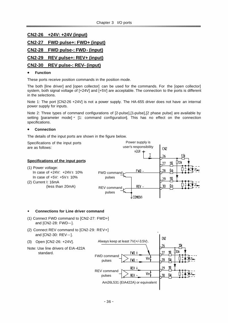
Chapter 3 I/O ports
- 36 -
CN2-26 +24V: +24V (input)
CN2-27 FWD pulse+: FWD+ (input)
CN2-28 FWD pulse-: FWD- (input)
CN2-29 REV pulse+: REV+ (input)
CN2-30 REV pulse-: REV- (input)
Function
These ports receive position commands in the position mode.
The both [line driver] and [open collector] can be used for the commands. For the [open collector] system, both signal voltage of [+24V] and [+5V] are acceptable. The connection to the ports is different in the selections.
Note 1: The port [CN2-26 +24V] is not a power supply. The HA-655 driver does not have an internal power supply for inputs.
Note 2: Three types of command configurations of [2-pulse],[1-pulse],[2 phase pulse] are available by setting [parameter mode] → [1: command configuration]. This has no effect on the connection specifications.
Connection
The details of the input ports are shown in the figure below.
Specifications of the input ports are as follows:
Specifications of the input ports
(1) Power voltage: In case of +24V: +24V±10% In case of +5V: +5V±10%
(2) Current I: 16mA (less than 20mA)
Connections for Line driver command
(1) Connect FWD command to [CN2-27: FWD+] and [CN2-28: FWD-].
(2) Connect REV command to [CN2-29: REV+] and [CN2-30: REV-].
(3) Open [CN2-26: +24V].
Note: Use line drivers of EIA-422A standard.
Power supply is user’s responsibility
FWD command pulses
REV command pulses
Am26L531 (EIA422A) or equivalent
FWD command pulses
REV command pulses
Always keep at least 7V(+/-3.5V) .

Chapter 3 I/O ports
- 37 -
Connection for open collector commands and +24V power supply
(1) Connect FWD command to [CN2-28: FWD-] and [+24V].
(2) Connect REV command to [CN2-30: REV-] and [+24V].
(3) Connect [+24V] of external power supply to [CN2-26: +24V].
(4) Plan the command circuit for the ports as follows: Supply voltage: +24V±10% Signal current: 16mA (less than 20mA)
Connection for open collector commands and +5V power supply
(1) Connect FWD command to [CN2-27: FWD+] and [CN2-28: FWD-].
(2) Connect REV command to [CN2-29: REV+] and [CN2-30: REV-].
(3) Open [CN2-26: +24V].
(4) Plan the command circuit for the ports as follows: Supply voltage: +5V±10% Signal current: 16mA (less than 20mA)
CN2-33 In-position: IN-POS (output)
Function
The signal is outputted when the error count becomes less than the value of [tune mode]→[4: in-position range]. The output may be used to confirm proper positioning.
Connection
(1) The figure to the right is a connection example of [CN2-33 in-position: IN-POS] port.
(2) Plan the output circuit for the ports as follows: Supply voltage: +24V or less Signal current: 40mA or less (for each port)
CN2-33 TLP127
CN2-43
IN-POS
OUT-COM
HA-655
Ry
The connections are deferent by the supply voltage. The pin numbers to be connected are deferent by the supply voltage of [+5V] or [+24V].The wrong connection may damage the driver.
CAUTION
FWD command pulses
REV command pulses
User’s power supply
+5V power supply & external resistance R1, R2 are user’s responsibility.
FWD command pulses
REV command pulses

Chapter 3 I/O ports
- 38 -
CN2-34 Alarm: ALARM (output)
Function
The output turns OFF when the HA-655 driver senses an alarm.
Connection
(1) An example of [CN2-34 alarm: ALARM] connection is shown in the figure below.
(2) Plan the output circuit for the ports as follows: Supply voltage: +24V or less Signal current: 40mA or less
CN2-37 Ready: READY (output)
Function
The output turns ON when the HA-655 driver is ready to drive.
CN2-34 TLP127
CN2-43
ALARM
OUT-COM
HA-655
Ry
Alarm
CN2-37 TLP127
CN2-43
READY
OUT-COM
HA-655
Ry
Ready

Chapter 3 I/O ports
- 39 -
CN2-38 Alarm-A+: ALM –A (output)
CN2-39 Alarm-B+: ALM –B (output)
CN2-40 Alarm-C+: ALM –C (output)
CN2-41 Alarm-D+: ALM –D (output)
Function
When The HA-655 driver senses an alarm, the 4-bit code corresponding to the alarm, shown in the table below, outputs from the ports.
alarm code Alarm description 4-bit
code ALM -D
ALM -C
ALM -B
ALM -A
alarm clear
10 Over speed 1011 ON OFF ON ON Impossible 20 Over load 0001 OFF OFF OFF ON Possible 21 Overheat 1000 ON OFF OFF OFF Impossible 30 Over current 1001 ON OFF OFF ON Impossible 41 Abnormal regeneration 1010 ON OFF ON OFF Impossible 50 Encoder failure 1101 ON ON OFF ON Impossible 51 Abnormal encoder signal 1101 ON ON OFF ON Impossible 52 UVW failure 1101 ON ON OFF ON Impossible 53 *ABS system failure 1101 ON ON OFF ON Impossible 54 *ABS MTD over flow 1101 ON ON OFF ON Impossible 55 *ABS multi-turn data error 1101 ON ON OFF ON Impossible 56 *ABS low battery voltage 1101 ON ON OFF ON Impossible 57 *ABS send data rule error 1101 ON ON OFF ON Impossible 60 Error counter overflow 0010 OFF OFF ON OFF Possible 70 Memory failure (RAM) 0101 OFF ON OFF ON Impossible 71 Memory failure (EEPROM) 0101 OFF ON OFF ON Impossible 76 CPU failure 0100 OFF ON OFF OFF Impossible
Notice: the alarm codes 53 through 57 are valid for absolute encoders only.
CN2-42 Phase-Z (OC): Z (output)
Function
The port outputs phase-Z pulse signal of the encoder. The signal is outputted one pulse per every one motor rotation. The signal may be used with the mechanical origin signal as a precise origin of the driven mechanism.
Connection
(1) An example of [CN2-42 phase-Z: Z] connection is shown in the figure to the right.
(2) The port is opto-isolated.
(3) Plan the output circuit for the ports as follows: Supply voltage: DC24V or less Signal current: 40mA or less
CN2-43 Output common: OUT-COM (output)
Function
This is the common port for the [CN2-33, 34, 38, 39, 40, 41, 42] ports.
CN2-42 TLP127
CN2-43
Z
OUT-COM
HA-655
Ry
Phase-Z

Chapter 3 I/O ports
- 40 -
CN2-44 Phase-A+(LD): A+ (output)
CN2-45 Phase-A-(LD): A- (output)
CN2-46 Phase-B+(LD): B+ (output)
CN2-47 Phase-B-(LD): B- (output)
CN2-48 Phase-Z+(LD): Z+ (output)
CN2-49 Phase-Z-(LD): Z- (output)
Function
These ports transmit encoder signals of Phase-A, -B, -Z through the line driver (26LS31).
Connection
Receive the signals using a line receiver (AM26LS32 or equivalent).
Notice: the alarm codes 53 through 57 are valid for absolute encoders only.
CN2-50 Ground: FG (output)
Function
Connect shield of cable.
Phase-A+
Phase-A- Phase-B+
Phase-Z+
Phase-B-
Phase-Z- 26LS31
44
45
48
49
46
47

Chapter 3 I/O ports
- 41 -
3-1-5 Connection examples in the position mode
<< for incremental encoder system >> The figure below shows a connection example in the position mode for [open collector] signals. The
command configuration is [2-pulse] type.
1.5k
26 1.5k +24V
33
37
38
39
40
41
42
43
IN-POS
ALARM
ALM-A
ALM-B
ALM-C
ALM-D
In-position
Alarm
Alarm code
Z
OUT-COM
Phase-Z
Output common44
45 46
47
Phase-A+
Phase-A- Phase-B+
Phase-B-
Phase-Z+
Phase-Z-48
49 26LS31 25
50
IN-COM
CLEAR
S-ON
FWD-IH
REV-IH
DC24V External power
Clear
Servo-ON
FWD inhibit
REV inhibit
2.2k
2 2.2k
3 2.2k
4
1/8
2.2k
5
0V
34
ALARM Ready
31
32
68k
FWD+
FWD-
REV+
REV-
+5V
COM(0V)
FWD pulse
REV pulse
+5V power supply & external resistance R1, R2 are user’s responsibility. Signal current should be 16mA.
110
0
27
28 R1
110
0
29
30 R2
Shield
HA-655-*-200
TB2
CN1
CN2
L/F
Transformer
Power AC200V (50/60Hz)
r
s
R
S
T
Line filter
L/F
NFB CP
TB1
AC Servo Actuator FHA-**C
M
R1
R2
U
V
W
Red
White
Black
Green/Yellow
Ground always.
Shield
+5V 1
0V 8
SD 5
SD 7
Black
Yellow
Blue
E
Red
Connector shell
Use shield pair cable. Clamp the end of shield surely to thecable-clamp of the connector.
Incremental Encoder
Line filter
Shield

Chapter 3 I/O ports
- 42 -
The figure below shows a connection example in the position mode for [line driver] signals. The command configuration is [2-pulse] type.
FWD pulse
1.5k
26 1.5k+24V
33
37
38
39
40
41
42
43
IN-POS
ALARM
ALM-A
ALM-B
ALM-C
ALM-D
In-position
Alarm
Alarm code
Z
OUT-COM
Phase-Z
Output common44
45 46
47
Phase-A+Phase-A-Phase-B+Phase-B-Phase-Z+Phase-Z-
48
49 26LS31 25
50
IN-COM
CLEAR
S-ON
FWD-IH
REV-IH
DC24V External power
Clear
Servo-ON
FWD inhibit
REV inhibit
2.2k
2 2.2k
3 2.2k
4
1/8
2.2k
5
0V
34
READY Ready
31
32
68k
REV pulse
110
0
27
28 110
0
29
30
Shield
HA-655-*-200
TB2
CN1
CN2
L/F
Transformer
Power AC200V (50/60Hz)
r
s
R
S
T
Line filter
L/F
NFB CP
TB1
AC Servo Actuator FHA-**C
M
R1
R2
U
V
W
Red
White
Black
Green/Yellow
Ground always.
Shield
+5V 1
0V 8
SD 5
SD 7
Black
Yellow
Blue
E
Red
Connector shell
Use shield pair cable. Clamp the end of shield surely to thecable-clamp of the connector.
Incremental Encoder
Line filter
Shield
FWD+
FWD-
REV+
REV-
Am26LS31(EIA422A) or equivalent
Always keep at least 7V(+/-3.5V).
Vin
Vin

Chapter 3 I/O ports
- 43 -
<< for absolute encoder system >> The figure below shows a connection example in the position mode for [open collector] signals. The
command configuration is [2-pulse] type.
1.5k
26 1.5k+24V
33
37
38
39
40
41
42
43
IN-POS
ALARM
ALM-A
ALM-B
ALM-C
ALM-D
In-position
Alarm
Alarm code
Z
OUT-COM
Phase-Z
Output common44
45 46
47
Phase-A+
Phase-A- Phase-B+ Phase-B- Phase-Z+ Phase-Z-
48
49 26LS31 25
50
HA-655-*-200
TB2
CN1
CN2
IN-COM
CLEAR
S-ON
FWD-IH
REV-IH
DC24V External power
Clear
Servo-ON
FWD inhibit
REV inhibit
2.2k
2 2.2k
3 2.2k
4
1/8
2.2k
10
2.2k
5
2.2k
11
ABS data request
ABS (multi-turn) data clear
A-REQ
A-CLEAR
0V
34
READY Ready
31
32
68k COM(0V)
FWD+
FWD-
REV+
REV-
+5V
FWD pulse
REV pulse
+5V power supply & external esistance R1, R2 are user’s responsibility. Signal current should be 16mA.
110
0
27
28 R1
110
0
29
30 R2
Shield
L/F
Transformer
Power AC200V (50/60Hz)
r
s
R
S
T
Line filter
L/F
NFB CP
TB1
AC Servo Actuator FHA-**C
M
R1
R2
U
V
W
Red
White
Black
Green/Yellow
Ground always.
Shield
Shield
CLR 6
+5V 1
0V 8
BAT- 4
SD 5
SD 7
White
Black
Yellow
Blue
BAT+ 2
E
Green
Orange Gray
Connector shell
Use shield pair cable
Clamp the end of shield surely to the cable-clamp of the connector.
Absolute encoder
Line filter

Chapter 3 I/O ports
- 44 -
The figure below shows a connection example in the position mode for [line driver] signals. The command configuration is [2-pulse] type.
1.5k
26 1.5k+24V
33
37
38
39
40
41
42
43
IN-POS
ALARM
ALM-A
ALM-B
ALM-C
ALM-D
In-position
Alarm
Alarm code
Z
OUT-COM
Phase-Z
Output common44
45 46
47
Phase-A+
Phase-A- Phase-B+ Phase-B- Phase-Z+ Phase-Z-
48
49 26LS31 25
50
HA-655-*-200
TB2
CN1
CN2
IN-COM
CLEAR
S-ON
FWD-IH
REV-IH
DC24V External power
Clear
Servo-ON
FWD inhibit
REV inhibit
2.2k
2 2.2k
3 2.2k
4
1/8
2.2k
10
2.2k
5
2.2k
11
ABS data request
ABS (multi-turn) data clear
A-REQ
A-CLEAR
0V
34
READY Ready
31
32
68k
110
0
27
28 110
0
29
30
Shield
L/F
Transformer
Power AC200V (50/60Hz)
r
s
R
S
T
Line filter
L/F
NFB CP
TB1
AC Servo Actuator FHA-**C
M
R1
R2
U
V
W
Red
White
Black
Green/Yellow
Ground always.
Shield
Shield
CLR 6
+5V 1
0V 8
BAT- 4
SD 5
SD 7
White
Black
Yellow
Blue
BAT+ 2
E
Green
Orange Gray
Connector shell
Use shield pair cable
Absolute encoder
Line filter
REV pulse
FWD+
FWD-
REV+
REV-
Am26LS31(EIA422A) or equivalent
Always keep at least 7V(+/-3.5V).
Vin
Vin
FWD pulse

Chapter 3 I/O ports
- 45 -
3-2 Speed mode 3-2-1 I/O port layout
<< for incremental encoder system >> The I/O port layout is shown as follows: ※ Do not use the pins marked “-”.
Pin Signal name Symbol I/O Pin Signal name Symbol I/O 1 Input signal common IN-COM Input 26 - - -
2 Clear CLEAR Input 27 - - -
3 Servo-ON S-ON Input 28 - - -
4 FWD enable FWD-EN Input 29 - - -
5 REV enable REV-EN Input 30 - - -
6 Command change CMD-CHG Input 31 Speed command SPD-CMD Input
7 - - NC 32 Speed command ground SG-GND Input
8 Input signal common IN-COM Input 33 Attained speed HI-SPD Output
9 - - - 34 Alarm ALARM Output
10 - - - 35 Ready READY Output
11 - - - 36 - - -
12 - - - 37 - - -
13 - - - 38 Alarm-A+ ALM-A Output
14 - - - 39 Alarm-B+ ALM-B Output
15 - - - 40 Alarm-C+ ALM-C Output
16 - - - 41 Alarm-D+ ALM-D Output
17 - - - 42 Phase-Z (OC) Z Output
18 - - - 43 Output common OUT-COM Output
19 - - - 44 Phase-A+(LD) A+ Output
20 - - - 45 Phase-A-(LD) A- Output
21 - - - 46 Phase-B+(LD) B+ Output
22 - - - 47 Phase-B-(LD) B- Output
23 Speed monitor SPD-MON Output 48 Phase-Z+(LD) Z+ Output
24 Current monitor CUR-MON Output 49 Phase-Z-(LD) Z- Output
25 Monitor ground GND Output
50 Frame ground FG Output
Note: OC: open collector, LD: line driver

Chapter 3 I/O ports
- 46 -
<< for absolute encoder system >> The I/O port layout is shown as follows: ※ Do not use the pins marked “-”.
Pin Signal name Symbol I/O Pin Signal name Symbol I/O 1 Input signal common IN-COM Input 26 - - -
2 Clear CLEAR Input 27 - - -
3 Servo-ON S-ON Input 28 - - -
4 FWD enable FWD-EN Input 29 - - -
5 REV enable REV-EN Input 30 - - -
6 Command change CMD-CHG Input 31 Speed command SPD-CMD Input
7 - - NC 32 Speed command ground SG-GND Input
8 Input signal common IN-COM Input 33 Attained speed HI-SPD Output
9 - - - 34 Alarm ALARM Output
10 ABS data request ABS-REQ Input 35 - - -
11 ABS (multi-turn) data clear ABS-CLEAR Input 36 - - -
12 - - - 37 Ready READY Output
13 - - - 38 Alarm-A+ ALM-A Output
14 - - - 39 Alarm-B+ ALM-B Output
15 - - - 40 Alarm-C+ ALM-C Output
16 - - - 41 Alarm-D+ ALM-D Output
17 - - - 42 Phase-Z (OC) Z Output
18 - - - 43 Output common OUT-COM Output
19 - - - 44 Phase-A+(LD) A+ Output
20 - - - 45 Phase-A-(LD) A- Output
21 - - - 46 Phase-B+(LD) B+ Output
22 - - - 47 Phase-B-(LD) B- Output
23 Speed monitor SPD-MON Output 48 Phase-Z+(LD) Z+ Output
24 Current monitor CUR-MON Output 49 Phase-Z-(LD) Z- Output
25 Monitor ground GND Output
50 Frame ground FG Output
Note: OC: open collector, LD: line driver
3-2-2 Models of I/O port connector CN2 The models of the CN2 connector are as follows:
Connector: 10150-3000VE 3M
Cover: 10350-52F0-008 3M

Chapter 3 I/O ports
- 47 -
3-2-3 I/O port connections in the speed mode This section describes the connections between the I/O ports and the host in the speed mode.
Inputs: The HA-655 driver provides six ports for inputs as shown in the figure to the right.
Specifications Voltage: DC24V±10% Current: 20mA or less (for each terminal)
An input port circuit is shown in the figure to the right. The ports marked with (*) are available for absolute encoder system only.
Connection
The HA-655 driver does not provide the power supply for input signals. A [+24V] power supply for the signals to [CN2-1: input signal common].
Outputs The HA-655 driver provides eight ports for outputs as shown in the figure to the right.
Specifications Port: Open collector Voltage: DC24V or less Current: 40mA or less (for each port)
All ports are insulated by opto-isolators.
An output circuit is shown in the figure to the right.
Connection
Connect output signals between their respective output ports and [CN2-43: output common] port.
IN+
IN-
2.2kΩ
10kΩ
Voltage DC24V±10% Current 20mA or less (for each terminal)
TLP120
HA-655
DC24V
0V
External power supply 0.01μF
CN2-33etc.
CN2-43
OUT-COM
74HC14 Ry
Attained speed
Alarm
Alarm codes
Phase-Z
Output common
Ready
HI-SPD
IN-COM
CLEAR
S-ON
FWD-EN
REV-EN
DC24V External power
CLEAR
Servo-ON
FWD enable
REV enable
2.2k
2 2.2k
3 2.2k
4
1/8
2.2k
6
2.2k
5
2.2k
11
* ABS data request
* ABS (multi-turn) data clear
A-REQ
A-CLEAR
0V
2.2k
10
CMD-CHG Command change

Chapter 3 I/O ports
- 48 -
3-2-4 I/O port functions in the speed mode
This section describes I/O port functions in the speed mode.
CN2-1 Input signal common: IN-COM (input)
Function
This is the common port for inputs: [CN2-2, -3, -4, -5, -6, -10, -11]. Supply external power for inputs from this port. Connection
Connect [+24V] external power supply for inputs here.
CN2-2 Clear: CLEAR (input)
Function
(3) If an alarm exists: This clears the alarm state, returns to operable state, and clears the error count to [0]. For alarms that cannot be cleared, shut off the control power once, and turn it on again.
(4) If no alarm exists: This clears the error count to [0].
Connection
Connect [NO-contact signal (a-contact)].
Refer to [CN2-1: input signal common].
CN2-3 Servo-ON: S-ON (input)
Function
This turns the servo power for the HA-655 driver ON and OFF.
When the input is ON, the servo power of the HA -655 driver is ON and the actuator can be driven. When OFF, the servo power turns OFF and the motor is free to rotate.
Connection
Connect [NO-contact signal (a-contact)].
Refer to [CN2-1: input signal common].

Chapter 3 I/O ports
- 49 -
CN2-4 FWD enable: FWD-EN (input)
CN2-5 REV enable: REV-EN (input)
Function
While the [FWD enable] is [ON] the actuator rotates forward when the [CN2-31 speed command: SPD-CMD] is [+]. In contrast, the actuator rotates in reverse for the [CN2-31] is [-].
While the [REV enable] is [ON] the actuator rotates in reverse when the [CN2-31 speed command: SPD-CMD] is [+]. Conversely, the actuator rotates forward when the [CN2-31] is [-].
When both signals of [FWD enable] and [REV enable] are [ON] or [OFF], the actuator is holding the position or zero speed depending on the setting of [parameter mode]→[7: zero clamp].
CN2-31 Speed cmd.: SPD-CMD +Command -Command
CN2-4 FWD enable: FWD-EN ON OFF ON OFF ON Zero clamp, zero speed REV rotation Zero clamp, zero speed FWD rotation CN2-5 REV enable:
REV-EN OFF FWD rotation Zero clamp, zero speed REV rotation Zero clamp, zero speed
Connection
Refer to [CN2-1: input signal common].
CN2-6 Command change: CMD-CHG(input)
Function
The function can operate the actuator without a command signal at the speed specified by [tune mode]→[6: internal speed command].
OFF: command speed
ON: internal speed
Connection
Refer to [CN2-1: input signal common].
CN2-8 Input common: IN-COM(input)
Function
The same functions as CN2-1
Servo-free state occurs at alarm occurrences during no power supply for the main circuit or the control circuit, or no servo-ON signal. If large unbalanced load is applied to actuators, the servo-free state may cause physical injury. CAUTION
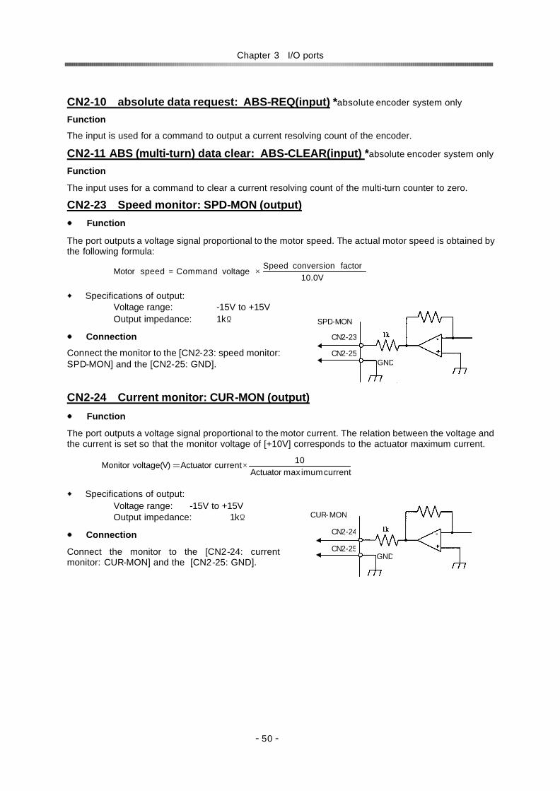
Chapter 3 I/O ports
- 50 -
CN2-10 absolute data request: ABS-REQ(input) *absolute encoder system only Function
The input is used for a command to output a current resolving count of the encoder.
CN2-11 ABS (multi-turn) data clear: ABS-CLEAR(input) *absolute encoder system only Function
The input uses for a command to clear a current resolving count of the multi-turn counter to zero.
CN2-23 Speed monitor: SPD-MON (output)
Function
The port outputs a voltage signal proportional to the motor speed. The actual motor speed is obtained by the following formula:
Specifications of output: Voltage range: -15V to +15V Output impedance: 1kΩ
Connection
Connect the monitor to the [CN2-23: speed monitor: SPD-MON] and the [CN2-25: GND].
CN2-24 Current monitor: CUR-MON (output)
Function
The port outputs a voltage signal proportional to the motor current. The relation between the voltage and the current is set so that the monitor voltage of [+10V] corresponds to the actuator maximum current.
Specifications of output: Voltage range: -15V to +15V Output impedance: 1kΩ
Connection
Connect the monitor to the [CN2-24: current monitor: CUR-MON] and the [CN2-25: GND].
SPD-MON
GND
CN2-23
CN2-25
CUR-MON
GND
CN2-24
CN2-25
10.0VfactorconversionSpeed
voltageCommandspeedMotor ×=
currentimummaxActuator10currentActuator (V)voltageMonitor ×=

Chapter 3 I/O ports
- 51 -
CN2-31 Speed command: SPD-CMD(input)
Function
Input the speed command voltage signal which is obtained by [parameter mode]→[9: speed conversion factor].
The direction of rotation is specified by the polarity (+/-) of the speed command and input signals of [CN2-4 FWD enable: FWD-EN ] and [CN2-5 REV enable: REV-EN].
While the [FWD enable]: is ON the actuator rotates forward when the [CN2-31 Speed command: SPD-CMD] is [+]. In contrast, the actuator rotates in reverse for the [CN2-31] is [-].
While the [REV enable]: is ON the actuator rotates in reverse the [CN2-31 Speed command: SPD-CMD] is [+]. In contrast, the actuator rotates forward when the [CN2-31] is [-].
When both signals [FWD enable] and [REV enable] are ON or OFF, depending on the setting of [parameter mode]→[7: zero clamp], the actuator is either holding the position (setting:1) or zero speed (setting: 0).
CN2-31 Speed cmd.: SPD-CMD +Command -Command
CN2-4 FWD enable: FWD-EN ON OFF ON OFF ON Zero clamp, zero speed REV rotation Zero clamp, zero speed FWD rotation CN2-5 REV enable:
REV-EN OFF FWD rotation Zero clamp, zero speed REV rotation Zero clamp, zero speed
Connection
Connect the voltage signal to the [CN2-31: speed command: SPD-COM] and the [CN2-32: SG-GND].
Plan the command circuit referring to the examples below.
By a potentiometer By host command
CN2-32 Speed command common: SG-GND(input)
Function
The port is the common ground for the [CN2-31 speed command: SPD-CMD].
SPD-COM
SG-GND
CN2-31
CN2-32
SPD-COM
SG-GND
CN2-31
CN2-32
15V
15V
R
R
VR
R: 1/2W 330Ω VR: 25HP-1; 2kΩ by Sakae Multi-turn wire-wound potentiometer
SPD-COM
SG-GND
CN2-31
CN2-32
+10Vto -10V
10.0VfactorconversionSpeed
voltagecommandSpeedspeedMotor ×=

Chapter 3 I/O ports
- 52 -
CN2-33 Attained speed: HI-SPD (output)
Function
The output turns ON when the motor rotates at a speed greater than the value of [tune mode]→[5: attained speed].
Connection
(1) The figure to the right shows an example of the [CN2-33 attained speed: HI-SPD] port connection.
(2) Plan the output circuit for the ports as follows: Supply voltage: DC24V or less Signal current: 50mA or less (for each port)
CN2-34 Alarm: ALARM (output)
Function
The output turns OFF when the HA-655 driver senses an alarm.
Connection
(1) An example of [CN2-34 alarm: ALARM] connection is shown in the figure below.
(2) Plan the output circuit for the ports as follows: Supply voltage: DC24V or less Signal current: 50mA or less
CN2-37 Ready: READY (output)
Function
The output turns ON when the HA-655 driver is ready to drive.
CN2-33 TLP127
CN2-43
HI-SPD
OUT-COM
HA-655
Ry
Attained speed
CN2-34 TLP127
CN2-43
ALARM
OUT-COM
HA-655
Ry
Alarm
CN2-37 TLP127
CN2-43
READY
OUT-COM
HA-655
Ry
Ready
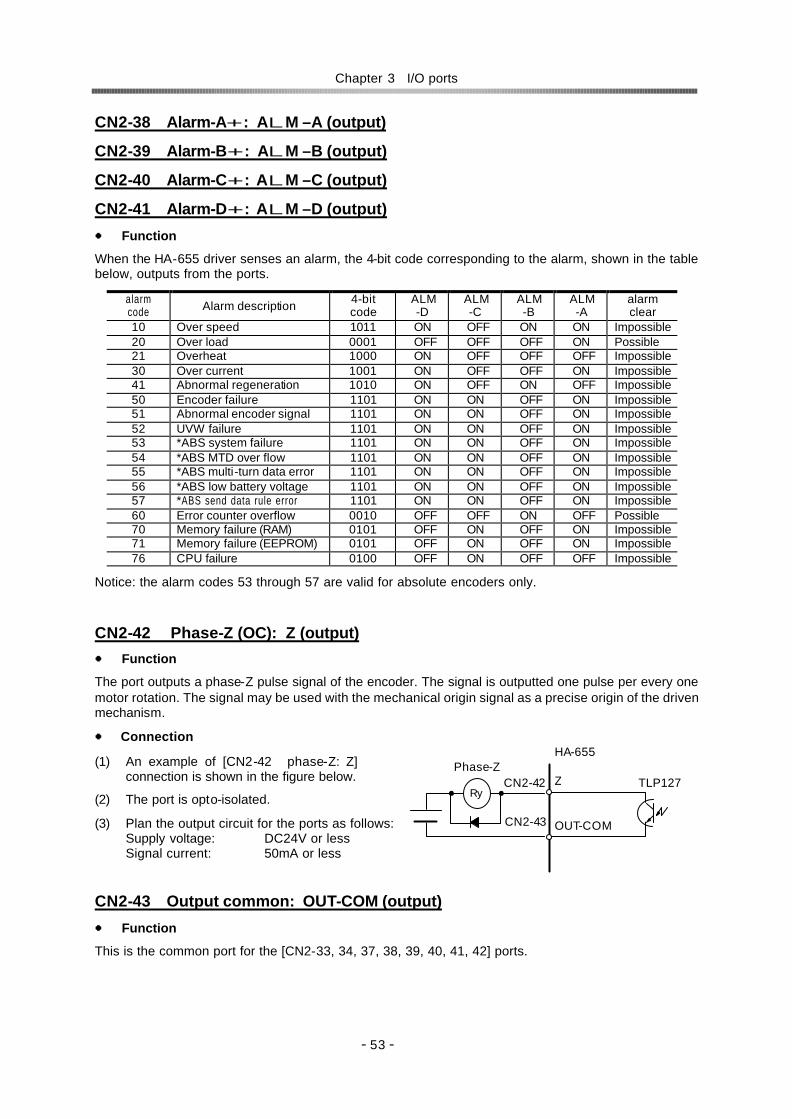
Chapter 3 I/O ports
- 53 -
CN2-38 Alarm-A+: ALM –A (output)
CN2-39 Alarm-B+: ALM –B (output)
CN2-40 Alarm-C+: ALM –C (output)
CN2-41 Alarm-D+: ALM –D (output)
Function
When the HA-655 driver senses an alarm, the 4-bit code corresponding to the alarm, shown in the table below, outputs from the ports.
alarm code Alarm description 4-bit
code ALM -D
ALM -C
ALM -B
ALM -A
alarm clear
10 Over speed 1011 ON OFF ON ON Impossible 20 Over load 0001 OFF OFF OFF ON Possible 21 Overheat 1000 ON OFF OFF OFF Impossible 30 Over current 1001 ON OFF OFF ON Impossible 41 Abnormal regeneration 1010 ON OFF ON OFF Impossible 50 Encoder failure 1101 ON ON OFF ON Impossible 51 Abnormal encoder signal 1101 ON ON OFF ON Impossible 52 UVW failure 1101 ON ON OFF ON Impossible 53 *ABS system failure 1101 ON ON OFF ON Impossible 54 *ABS MTD over flow 1101 ON ON OFF ON Impossible 55 *ABS multi-turn data error 1101 ON ON OFF ON Impossible 56 *ABS low battery voltage 1101 ON ON OFF ON Impossible 57 *ABS send data rule error 1101 ON ON OFF ON Impossible 60 Error counter overflow 0010 OFF OFF ON OFF Possible 70 Memory failure (RAM) 0101 OFF ON OFF ON Impossible 71 Memory failure (EEPROM) 0101 OFF ON OFF ON Impossible 76 CPU failure 0100 OFF ON OFF OFF Impossible
Notice: the alarm codes 53 through 57 are valid for absolute encoders only.
CN2-42 Phase-Z (OC): Z (output)
Function
The port outputs a phase-Z pulse signal of the encoder. The signal is outputted one pulse per every one motor rotation. The signal may be used with the mechanical origin signal as a precise origin of the driven mechanism.
Connection
(1) An example of [CN2-42 phase-Z: Z] connection is shown in the figure below.
(2) The port is opto-isolated.
(3) Plan the output circuit for the ports as follows: Supply voltage: DC24V or less Signal current: 50mA or less
CN2-43 Output common: OUT-COM (output)
Function
This is the common port for the [CN2-33, 34, 37, 38, 39, 40, 41, 42] ports.
CN2-42 TLP127
CN2-43
Z
OUT-COM
HA-655
Ry
Phase-Z

Chapter 3 I/O ports
- 54 -
CN2-44 Phase-A+(LD): A+ (output)
CN2-45 Phase-A-(LD): A- (output)
CN2-46 Phase-B+(LD): B+ (output)
CN2-47 Phase-B-(LD): B- (output)
CN2-48 Phase-Z+(LD): Z+ (output)
CN2-49 Phase-Z-(LD): Z- (output)
Function
These ports transmit encoder signals of Phase-A, -B, -Z from the line driver (26LS31).
Connection
Receive the signals by using line receiver (AM26LS32 or equivalent).
CN2-50 Ground: FG (output)
Function
Connect shield of the cable.
Phase-A+ Phase-A- Phase-B+
Phase-Z+ Phase-B-
Phase-Z-
44
45
46
47
48
49 26LS31

Chapter 3 I/O ports
- 55 -
3-2-5 Connection examples in the speed mode
<< for incremental encoder system >> The figure below shows a connection example in the speed mode for an incremental encoder
system.
1.5k
26 1.5k
33
37
38
39
40
41
42
43
IN-POS
ALARM
ALM-A
ALM-B
ALM-C
ALM-D
In-position
Alarm
Alarm code
Z
OUT-COM
Phase-Z
Output common44
45 46
47
Phase-A+Phase-A-Phase-B+Phase-B-Phase-Z+Phase-Z-
48
49 26LS31 25
50
IN-COM
CLEAR
S-ON
FWD-EN
REV-EN
DC24V External power
Clear
Servo-ON
FWD enable
REV enable
2.2k
2 2.2k
3 2.2k
4
1/8
2.2k
5
0V
34
READY Ready
31
32
68k
110
0
27
28 110
0
29
30
Shield
HA-655-*-200
TB2
CN1
CN2
L/F
Transformer
Power AC200V (50/60Hz)
r
s
R
S
T
Line filter
L/F
NFB CP
TB1
AC Servo Actuator FHA-**C
M
R1
R2
U
V
W
Red
White
Black
Green/Yellow
Ground always.
Shield
+5V 1
0V 8
SD 5
SD 7
Black
Yellow
Blue
E
Red
Connector shell
Use shield pair cable. Clamp the end of shield surely to thecable-clamp of the connector.
Incremental Encoder
Line filter
Shield
Spd. com. common
Speed command SPD-CMD
SG-GND
2.2k
6 CMD-CHG Command change

Chapter 3 I/O ports
- 56 -
<< for absolute encoder system >> The figure below shows a connection example in the speed for an absolute encoder system..
Spd. com. common
Speed command SPD-CMD
SG-GND
1.5k
26 1.5k
33
37
38
39
40
41
42
43
HI-SPD
ALARM
ALM-A
ALM-B
ALM-C
ALM-D
Attained speed
Alarm
Alarm code
Z
OUT-COM
Phase-Z
Output common44
45 46
47
Phase-A+
Phase-A- Phase-B+
Phase-B- Phase-Z+
Phase-Z-
48
49 26LS31 25
50
HA-655-*-200
TB2
CN1
CN2
IN-COM
CLEAR
S-ON
FWD-EN
REV-EN
DC24V External power
Clear
Servo-ON
FWD enable
REV enable
2.2k
2 2.2k
3 2.2k
4
1/8
2.2k
10
2.2k
5
2.2k
11
ABS data request
ABS (multi-turn) data clear
ABS-REQ
ABS-CLEAR
0V
34
READY Ready
31
32
68k
110
0
27
28 110
0
29
30
Shield
L/F
Transformer
Power AC200V (50/60Hz)
r
s
R
S
T
Line filter
L/F
NFB CP
TB1
AC Servo Actuator FHA-**C
M
R1
R2
U
V
W
Red
White
Black
Green/Yellow
Ground always.
Shield
Shield
CLR 6
+5V 1
0V 8
BAT- 4
SD 5
SD 7
White
Black
Yellow
Blue
BAT+ 2
E
Green
Orange Gray
Connector shell
Use shield pair cable
Clamp the end of shield surely to the cable-clamp of the connector.
Absolute encoder
CMD-CHG Command change
2.2k
6

Chapter 4 Installing the HA-655 driver
- 57 -
Chapter 4 Installing HA-655 driver 4-1 Receiving Inspection Check the followings when products are received.
Inspection procedure (1) Check the shipping container and item for any damage that may have been caused during
transportation. If the item is damaged, immediately contact the dealer it was purchased from.
(2) The label, shown in the figure to the right, is attached on the right side of the HA-655 driver. Confirm the products you ordered by comparing with the model on the [POWER] line of the label. If it is different, immediately contact the dealer it was purchased from.
The model code is interpreted as follows:
(3) Under the [ADJ.] line, the code of the FHA-C series actuator to be driven by the HA-655 driver is typed. To avoid confusion, group the actuator with its appropriate driver.
(4) The input voltage for the HA-655 driver is identified with the last code of the model code in the [TYPE] frame on the label.
200: 3-phase or single-phase 200V
100: single-phase 100V
If the voltage to be supplied is different from the voltage on the label, immediately contact the dealer from who it was purchased.
Only connect the actuator specified on the driver label.
The HA-655 driver has been tuned for the actuator specified on the driver label. The wrong combination of HA-655 drivers and actuators may cause low torque problems orover current that may cause physical injury and fire. CAUTION
Do not supply voltage other than the voltage specified on the label.The wrong power supply voltage may damage the HA-655 driver resulting physicalinjury and fire.
CAUTION
HA-655-2A-200 AC servo driver
655 series Nominal current
Input voltage
Available encoder void incremental encoder model A absolute encoder model
200 AC200V 100 AC100V
2 2.4A 4 4.0A

Chapter 4 Installing the HA-655 driver
- 58 -
4-2 Notices on handling The HA-655 drivers are electronic devices. Handle them with care and take the following precautions:
(1) Because the case is made of plastic, do not apply excess force or shock.
(2) The vibration resistance of the HA-655 driver is 4.9m/s2(10 to 55Hz). Do not mount or transport the HA-655 driver in a manner where it would be subjected to high levels of vibration.
(3) Do not put the HA-655 driver on the place from where it can easily fall down.
(4) Do not put anything on the HA-655 driver. The case of the driver may break.
(5) Do not drop screws, solder balls, wire chips, or any other foreign objects through the ventilation gaps of the HA-655 driver.
(6) Do not insert electric wire, steel wire, or a screwdriverthrough the ventilation gaps of the HA-655 driver.
(7) Handle the terminal cover carefully. Do not use the HA-655 driver without the terminal cover. Failure to observe this caution may result in electric shock or personal injury.
(8) The allowable storage temperature is from -20 to +85. Do not expose it to sunlight for long periods of time, and do not store it in areas where temperatures are likely to fluctuate greatly.
(9) The allowable storage relative humidity is less than 95%. Do not store it in highly humid place or in areas where temperatures are likely to fluctuate greatly.
(10) Do not store the HA-655 driver in areas where in corrosive gas or particles may be present.
CAUTION

Chapter 4 Installing the HA-655 driver
- 59 -
4-3 Location and installation 4-3-1 Environment of location The environmental conditions of the location are as follows:
Service temperature: 0 to 50 Use the driver in a cabinet. The temperature in the cabinet may be higher than the atmosphere because of power loss of the housed devices and its size. Plan the cabinet size, ventilation system, and device locations so the ambient temperature of the driver, which is always less than 50.
Service humidity: less than 95% relative humidity, without condensation Make sure that water condensation does not occur due to fluctuating temperatures in the storage area or because of frequent heat-and-cool (run-and-stop) operations.
Vibration: less than 4.9m/sec2(0.5G)(10Hz to 55Hz) When there is a great deal of vibration near the driver, attach a shock absorber under the base to dampen the vibration.
Impact: less than 98m/s2 (10G)
Make sure that dust, water condensation, metal powder, corrosive gas, water, water drops, or oil mist is not exposed to the HA -655 driver. Do not install the driver in a corrosive gas environment, because the gas may cause damage to connecting parts (connectors, etc.).
Install the driver in a cabinet. Do not expose it to the sunlight.
4-3-2 Notices on installation Install the driver vertically and allow for wide spaces for air to flow sufficiently.
Leave 30mm or more from walls, 50mm or more from floor and 100mm from ceiling, and adjacent devices as shown the figure below.
When planning the ventilation system for the cabinet refer to the table below, which lists the power consumption of the HA-655 driver.
Driver HA-655-2 HA-655-4 Actuator FHA-17C FHA-25C FHA-32C FHA-40C Power
consumption 30W 40W 50W 60W

Chapter 4 Installing the HA-655 driver
- 60 -
4-3-3 Installing The HA-655 driver should be mounted on a wall as shown in the figure to the right.
Two mounting holes are provided on the back of the driver. The thickness of the wall should be more than 2mm.
Procedure (1) Screw an M4 machine screw in the
tapped hole on the wall.
(2) Put the lower mounting hole (cut hole) of the back of the driver on the M4 screw.
(3) Screw tightly through the upper mounting hole with M4 screws.
(4) Tighten the lower M4 screw.
4-4 Suppressing noise The HA-655 driver employs an IPM (power module) with a PWM control for main circuit. As the IPM generates switching noise by high-speed power switching, the noise may cause incorrect motion of other equipment or radio noise interference due to poor cabling or poor grounding.
In addition, it is necessary to provide proper cable management in order to suppress incorrect motion of the HA-655 driver by external noise from hosts, which contain electronic components, such as a CPU.
To prevent troubles by noise emissions always install cabling and grounding as follows:
4-4-1 Devices for grounding Refer to the figure below when grounding all devices of the system.
Note 1: For the grounding line filters refer to [4-4-2 installing noise filter].
HD Noise Filter
Power Trans- former
Noise Filter
Power Trans- former
Noise Filter
Ground
Customer’s signal generating devices as a program logic controller
CN2
E
M
Note1 Note1
R S T
U V W
CN1
HA-655
3.5mm2 or thicker
Grounding to the earth One-point-grounding is essential. 3.5mm2 or thicker
Servo Actuator
Power Supply 3-phases
Noise Filter
r s
Note1
3.5mm2 or thicker
Wal
l
5
5

Chapter 4 Installing the HA-655 driver
- 61 -
Grounding motor frame
When actuators are grounded at driven machine through the motor frame, current flows through floating capacity (Cf) of the motor from power amplifier of the driver. To avoid influence of the current, always connect the ground terminal (motor frame) of the motor to the ground terminal of the driver, and connect the ground terminal of the driver to the ground directly.
Grounding ducts
When the motor cables are housed in a metal conduit or a metal box, ground their metal parts. The ground should be connected to earth at a single point.
4-4-2 Installing noise filters Noise filters are recommended to guard against incorrect motion caused by impulse noise that may be emitted from power line and to suppress noise emissions to the line from inside of the driver.
When several drivers are used, install noise filters for each driver.
Select bi-directional noise filters that can suppress external and internal noise.
Recommended noise filters are listed in the figure below:
driver Model Ratings Manufacturer HA-655-2 Single
phase HA-655-4 SUP-P10H-EPR 250V, 10A
HA-655-2 3SUP-H5H-ER-4 250V, 5A Mai
n po
wer
Three phase HA-655-4 3SUP-H10H-ER-4 250V, 10A
Control power All models SUP-P5H-EPR 250V, 5A
Okaya electric.
Install the noise filters and the HA-655 driver as near as possible with one another.
Install the noise filters to the lines of the electric devices other than the HA-655 driver in the same way. Always install the noise filters to the source of high frequency noise, such as electric welders and electrical discharge machines.
Incorrect use of noise filters can seriously reduce its effectiveness. Inspect them with the following instructions:
Separate the filtered side and the unfiltered side of the power supply cables from each other. Do not bundle both together. Do not encase them within the same duct.
Do not bundle the grounding cable with the filtered side of power cables or signal wires. Do not encase them within the same duct.
Avoid daisy-chain wiring of ground cables. Ground them to a frame box or ground plate at a single point.
Filter
Ground in
Filter
Ground in Box Ground in Box
×
(a)
Filter Filter
Ground in Box Ground in Box
×
Grounding wires near power lines is
acceptable.
(b)
Filter Filter
Ground in Box Ground in Box
×
E E
Wire Shield
E E
Wire Shield
(c)

Chapter 4 Installing HA-655 driver
- 62 -
4-4-3 Instructions for cabling In addition to the noise suppression mentioned previously, one must also follow these instructions:
(1) Use twisted pair cables for I/O signals, and for encoder signals cables. When a host controls several drivers, prepare I/O signal cables for each driver individually.
(2) Make the length of signal cables as short as possible.
(a) I/O signal cable: 3m or less
(b) Encoder signal cable (user’s responsibility): 20m or less, providing that the condition of wire conductivity is less than 0.04 ohm/m.
Optional cables of 3m/5m/10m long are available.
(3) Install surge protector devices to magnetic relays coils, magnetic switches, and solenoids.
(4) Separate power cables (power source cables and motor cables) and I/O signal cables by more than 30cm. Do not encase both cables in one pipe or duct, and do not bundle them.
(5) Do not open the end of analog signal cables such as speed signal cables.
(6) As the HA-655 driver is designed for industrial use, it provides no specific radio interference provisions. Accordingly, line filters should be inserted for the power supply cables in the event that the driver:
- is used in the vicinity of private residences.
-causes apparent radio interference.

Chapter 4 Installing HA-655 driver
- 63 -
4-5 Connecting power cables 4-5-1 Instructions for power supply
4-5-2 Power cable and ground cable The minimum allowable wire sizes of power cables, ground wires, and other cables are listed below. We recommend the thickest wires possible.
Allowable Wire Sizes (mm2) HA-655-2 HA-655-4
Terminals and
Connectors Symbol
FHA-17C FHA-25C FHA-32C FHA-40C Main Power Supply R,S,T 1.25 1.25 1.25 1.25
Control Power Supply r, s 1.25 1.25 1.25 1.25 Motor Leads U,V,W,E 0.75 Note 3 0.75 Note 3 1.25 Note 3 1.25 Note 3
Ground Ground mark 3.5 3.5 3.5 3.5 Regeneration Resister R1,R2 0.75 0.75 1.25 1.25
Encoder Port CN1 0.3mm2 twist pair shielded cable Note 3. I/O Signal Port CN2 0.35mm2 twist pair, or twist pair whole-shielded cable
Note 1: When bundling wires or encasing into conduits (plastic or metal pipes), use the wire of one size thicker.
Note 2: In hot environments, such as the temperature in a cabinet, use heat-resistant cable (IV or HIV).
Note 3: Optional cables of 3m/5m/10m long are available as follows: for a motor: EWC-MB * * -M08-TN
for an incremental encoder: EWC-E * * -B04-3M14
for an absolute encoder: EWC-S * * -B08-3M14
(1) Before connecting the power cable to the HA-655 driver, turn-OFF the electricity to avoid electric shock.
(2) Connect the power cable to the HA-655 driver only after installing the driver on a wall.
(3) Ground the HA-655 driver, to avoid electric shock, malfunctions caused by external noise, and for the suppression of radio noise emissions.
CAUTION
Cable length 03 3m 05 5m 10 10m

Chapter 4 Installing HA-655 driver
- 64 -
4-5-3 Connecting power cables The terminal block for the power is located on the front panel of the HA -655 driver. There is no phase order in connection to three-phase power lines.
Shown the figure to the right, strip the end of wires of the power supply cable and the motor cable, and connect wires to each terminal firmly.
Install an isolation transformer and noise filters in the power lines to avoid electric shock and to guard against malfunctions caused by external noise.
The driver contains a surge-current-suppress-circuit of capacitor type. Although the circuit reduces line voltage fluctuation, avoid daisy-chain wiring of the power lines, and connect units with a main switch.
4-5-4 Isolation transformer The use of an isolation transformer is recommended to prevent problems caused by improper grounding and external noises.
Optional transformers are available as follows:
FHA-17C FHA-25C FHA-32C FHA-40C Actuator Unit Voltage 200V 200V 200V 200V
HA-655-2 PT1-20004 - HA-655-4 - PT1-20008
Refer to appendix 1 for the details of the transformers.
HA-655
Main switch
Other device
Other device
Power
Other device
Other device
Power
Good connection Bad connection
Main switch
HA-655
PT1-200 04-200
Ins. transformer: PT1 series
2nd volt. 200: AC 200V
2nd cur. 04: 4A 08: 8A
Prim. volt 100: AC100V 115: AC115V 200: AC200V 220: AC220V
7mm
R S T
Noise filter
3-phase power (200V) r s
NF
NF
HA-655-•-200
R S T Noise filter
Single phase power (200V) r
s NF
NF
Isolation transformer
Isolation transformer
Model:MVSTBR2.5/5-ST-5.08(Phoenix contact)

Chapter 4 Installing HA-655 driver
- 65 -
4-5-5 Protecting power lines We recommended protecting the driver by installing a circuit breaker or fuses from surge current at power-ON. Select the recommended circuit breakers or fuses using the table below.
Combinations of actuator and driver FHA-17C HA-655-2
FHA-25C HA-655-2
FHA-32C HA-655-4
FHA-40C HA-655-4
Interrupting current of MCB or fuse (A) 5 10 15 20
Required capacity per driver (kVA) Note 1 0.1 0.3 0.5 0.7
Surge current at power ON (A) Note 2 15 15 15 15 Note 1: The value is for continuous duty at rated output. Note 2: The values are quoted at ambient temperature of 25 degC. Note 3: The values are quoted for actuators and drivers for 200V power supply.
4-6 Connecting a ground wire The minimum allowable size of ground wire is listed in the table below. Use the thickest wire possible.
Allowable Wire Sizes (mm2) HA-655-2 HA-655-4
Terminals and
Connectors Symbol
FHA-17C FHA-25C FHA-32C FHA-40C Ground(PE) Ground mark 3.5 3.5 3.5 3.5
The HA-655 driver provides two ground terminals as shown the figure to the right. Connect the ground wire from the cabinet to either terminal and connect the ground wire from the actuator to the other terminal.
The leakage current is at least 3.5 mA. Therefore terminals must have a section of at least 3.5 mm2 and be wired using ring terminals.
4-7 Connecting motor and regeneration resistor cables Connect the actuator cable to [U,V,W] terminals of the HA-655 driver as shown in the figure below. Refer to the phase order of the actuator cable in the actuator manual and connect the end terminal of cables to the driver terminal that have the same symbol.
Shown the figure to the right, strip the end of wires of the motor cable and resistor cables, and connect wires to each terminal firmly.
When a regeneration resistor is required, connect its wires to [R1, R2] terminals.
Ground for cabinet
Ground for actuator
7mm
HA-655-•
Model:MVSTBR2.5/6-ST-5.08(Phoenix contact)
U V W
R1 R2
Regeneration resistor
Actuator

Chapter 4 Installing HA-655 driver
- 66 -
4-8 Connecting cables for the encoder and the I/O 4-8-1 Preparing the encoder cable and the I/O cable Follow these instructions for the preparation of the encoder cable and the I/O cable.
(1) Use twisted pair cables for I/O signal cables and for encoder signal cables. When a host controls several drivers, install I/O signal cables for each driver individually.
(2) Make the length of signal cables as short as possible.
① I/O signal cable: 3m or less
② Encoder signal cable (user’s responsibility): 20m or less, providing that the condition of wire conductivity is less than 0.04 ohm/m.
Optional cables of 3m/5m/10m long are available.
(3) Separate power cables (power source cables and motor cables) and I/O signal cables more than 30cm. Do not encase both cables in one pipe or duct, nor bundle them.
(4) Do not open the end of analog signal cables as speed signal cables.
Allowable Wire Sizes (mm2) HA-655-2 HA-655-4
Terminals and
Connectors Symbol
FHA-17C FHA-25C FHA-32C FHA-40C Encoder Port CN1 0.3mm2 twist pair shielded cable
I/O Signal Port CN2 0.35mm2 twist pair, or twist pair whole-shielded cable
4-8-2 Pin layouts of encoder connector (CN1) The models and the pin layout of the encoder connector are as follows:
Plug: model: 10114-3000VE manufacturer: 3M Shell: model: 10314-52F0-008 manufacturer: 3M
5 SD
3 +5V
1 +5V
7 SD
6 NC +5V
4 +5V
2 +5V
13 FG
11 NC
9 NC
14 FG
12 NC
10 0V
8 0V
The layout shows the soldering side.
for incremental encoder
5 SD
3 NC
1 +5V
7 SD
6 CLR +5V
4 BAT-
2 BAT;
13 NC
11 NC
9 NC
14 FG
12 NC
10 NC
8 0V
The layout shows the soldering side.
for absolute encoder

Chapter 4 Installing HA-655 driver
- 67 -
4-8-3 Pin layouts of the I/O signal connector (CN2) The models and the pin layout of the encoder connector are as follows:
Plug: model: 10150-3000VE manufacturer: 3M Shell: model: 10350-52F0-008 manufacturer: 3M
Position mode
Speed mode
4-8-4 Connecting cables for the encoder and I/O signals Firmly connect both connectors of the encoder cable and the I/O signal cable to [CN1] and [CN2] sockets respectively.
Note 1: The layout shows the soldering side. Note2: ABS-REQ and ABS-CLEAR are available for the absolute encoder system.
5 REV-
IH
3 S-ON
1 INP- COM
7
6
4 FWD-
IH
2 CLEAR
13 11 ABS-
CLEAR
9
14 12 10 ABS- REQ
8 INPUT COM
19 17 15 21
20 18 16
25 GND
23 SPD -MON
24 CUR -MON
22
30 REV-
28 FWD-
26 +24V
32
31 29 REV+
27 FWD+
38
ALM -A
36 34 A L A R M
39 ALM -B
37 READY
35 33 IN-
POS 44 A+
42 Z
40 ALM -C
46 B+
45 A-
43 OUT- COM
41 ALM -D
50 FG
48 Z+
49 Z-
47 B-
Encoder connector
CN1 socket
CN2 socket
I/O signal connector
5 REV- EN
3 S-ON
1 INP- COM
7
6 CMD- CHG
4 FWD-
EN
2 CLEAR
13 11 ABS-
CLEAR
9
14 12 10 ABS- REQ
8 INPUT COM
19 17 15 21
20 18 16
25 GND
23 SPD -MON
24 CUR -MON
22
30 28 26 32 SG-
COM
31 SPD- COM
29 27
38 ALM -A
36 34 A L A R M
39 ALM -B
37 READY
35 33 HI-
SPD 44 A+
42 Z
40 ALM -C
46 B+
45 A-
43 OUT- COM
41 ALM -D
50 FG
48 Z+
49 Z-
47 B-
Note 1: The layout shows the soldering side. Note2: ABS-REQ and ABS-CLEAR are available for the absolute encoder system.

Chapter 4 Installing HA-655 driver
- 68 -
4-9 Power ON and OFF sequences Plan power ON and power OFF sequences with the timing shown in the figures below.
Power ON sequence << for incremental encoder system >>
<< for absolute encoder system >>
Note 1: Both output signals of phase-A and phase-B are settled at LOW-level. To settle at LOW-level, at least three pulses are outputted. Make a sequence for the host device ignoring outputted pulses while the phase-Z is LOW-level before generating a unique pulse train, and during other LOW-level duration of the phase-Z signal.
Note 2: An absolute pulse train for single-turn encoder is outputted after around 1 ms of outputting phase-Z signal.
Note 3: The servo-ON signal is unaccepted until completing the transmission of a set of unique pulse trains by the [absolute data request] signal.
Note 4: The [alarm 57] may occurs if the single-turn encoder rotates more than 127 resolvable position while the multi-turn counter is transmitting a unique pulse train.
0ms(min)
4ms(max)
3ms(max)
0ms(min)
20ms(max)
Servo ON is available.
Commands are acceptable.
Control power OFF⇒ON
Main power OFF⇒ON
Ready outputting
Alarm outputting
Servo ON inputting
Commands inputting
Servo ON
available.
Main power OFF⇒ON
Control power OFF⇒ON
Ready outputting
Phase-Z outputting
Servo ON inputting
ABS data request inputting
84µs
0ms(min)
4s(max)
3ms(max)
0ms(min) 10ms(max)
90ms(max)
840µs
90ms(max)
Note 4
Note 1 Multi-turn
data Note
1 Single turn data
note 2 Phase-A, -B outputting
Alarm outputting
Incremental data

Chapter 4 Installing HA-655 driver
- 69 -
Power OFF sequence
Switch for main power operation
Plan the sequence circuit to operate the switch for main power individually by [alarm] signal and [emergency stop] signal.
Notices for switching main power
Since the HA-655 driver provides a capacitor for an input filter of a rectifier circuit, large transient current flows at every operation of main power switch. If the switching operation is too frequent, resisters for suppressing the transient current may deteriorate.
The switching frequency should not exceed 5 times in an hour and 30 times in a day. Furthermore, the interval between turning OFF and ON should keep more than 30 seconds.
Do not make switching operation (turning ON or OFF) at the state that the servo -ON [CN2-3:S-ON] is ON.
Min.0ms
Max.20ms Min.20ms Min.0ms
ON
ON
OFF
OFF
Not acceptable
Servo-ON
Input
OFF
Alarm
Reset
Main power
Alarm
Servo-ON
Commands Output
Output
Input
ON⇒OFF
ON⇒OFF Power for control

Chapter 5 Operations
- 70 -
Chapter 5 Operations Follow these instructions prior to operations.
5-1 Test run
5-1-1 Driving an actuator without load Drive the actuator only during the test run.
Reason for a test run
(1) Verifying the power cable wiring
(2) Verifying the actuator cable wiring (the servomotor cable and the encoder cable)
(3) Verifying the I/O signal communication with the host device
Procedure of test run
Power-ON and verifying power circuit
(1) Turn on power to the driver. Turn on power to the host.
Make sure there is not an abnormality.
⇒ Indication (monitor mode) appears on the display of the HA-655 driver.
I If no indication appears, there may be faulty power connections. Shut off power and inspect the wiring.
1. Inspect the cabling before turning the power ON and correct poor cabling if necessary.
(1) Is the cabling correct? (2) Is there any temporary cabling? Are all wires connected to the
terminals? (3) Are there any loose terminal connections? (4) Are the wires grounded properly?
2. Never wire the unit or make changes to the wiring while the power is ON. Turn the power OFF first.
3. Clean around the equipment. Make sure there are no wire chips ortools in the equipment.
4. When two or more persons are working on the equipment, make sure all are alerted and safe before power is restored to the machine.
CAUTION
1. Complete the test run before actual operation.
2. Drive the actuator only during the test run; disconnect the actuator from the driven mechanism or load. CAUTION
D O W N U P A D J S E T
6th digit
5th digit 4th digit 3rd digit
2nd digit 1st digit
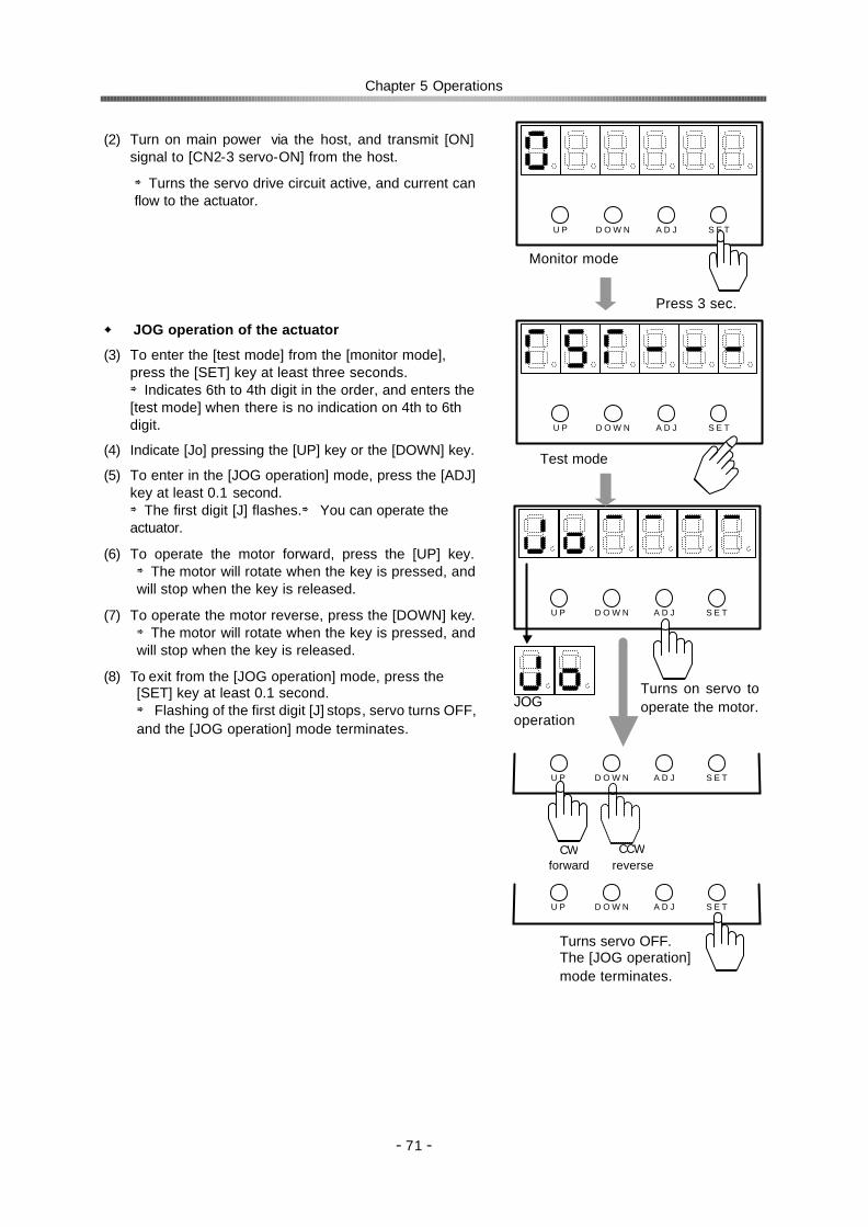
Chapter 5 Operations
- 71 -
(2) Turn on main power via the host, and transmit [ON] signal to [CN2-3 servo-ON] from the host.
⇒Turns the servo drive circuit active, and current can flow to the actuator.
JOG operation of the actuator
(3) To enter the [test mode] from the [monitor mode], press the [SET] key at least three seconds. ⇒Indicates 6th to 4th digit in the order, and enters the [test mode] when there is no indication on 4th to 6th digit.
(4) Indicate [Jo] pressing the [UP] key or the [DOWN] key.
(5) To enter in the [JOG operation] mode, press the [ADJ] key at least 0.1 second. ⇒The first digit [J] flashes.⇒ You can operate the actuator.
(6) To operate the motor forward, press the [UP] key. ⇒The motor will rotate when the key is pressed, and will stop when the key is released.
(7) To operate the motor reverse, press the [DOWN] key. ⇒The motor will rotate when the key is pressed, and will stop when the key is released.
(8) To exit from the [JOG operation] mode, press the [SET] key at least 0.1 second. ⇒ Flashing of the first digit [J] stops, servo turns OFF, and the [JOG operation] mode terminates.
D O W N U P A D J S E T
JOG operation
CW forward
CCW reverse
Turns on servo to operate the motor.
D O W N U P A D J S E T
D O W N U P A D J S E T
Turns servo OFF. The [JOG operation] mode terminates.
A D J
D O W N U P A D J S E T
D O W N U P S E T
Monitor mode
Press 3 sec.
Test mode

Chapter 5 Operations
- 72 -
Verifying Input signals
(9) Indicate [c: I/O monitor] by pressing the [UP] key or the [DOWN] key. The forth digit indicates output states and the sixth indicates input states.
(10) Signal to [CN2-2]~[CN2-6] ports from the host.
Verify the indications as shown in the figure below.
D O W N U P A D J S E T
Output Input
CN2-3: Servo-ON
Output Input CN2-2: Clear
CN2-4: FWD inhibit(pos. mode) FWD enable(spd. mode)
CN2-5: REV inhibit (pos. mode) REV enable (spd. mode)
CN2-6: Command
change (spd. mode)
CN2-33: In-position (pos. mode) Attained speed (spd. mode)
CN2-34: Alarm
CN2-41: Alarm code D
CN2-39: Alarm code B
CN2-38: Alarm code A
CN2-40: Alarm code C

Chapter 5 Operations
- 73 -
Verifying output signals
(11) Indicate [Inp: output port operation] by pressing the [UP] key or [DOWN] key.
(12) To operate output ports, press the [ADJ] key at least 0.1second. ⇒The first digit flashes. You can operate output ports. (Re-pressing the [ADJ] key at least 0.1 second inhibits [output port operation].
(13) Press the [UP] key to specify which output port is to be operated. ⇒Every pressing the key shifts the code number in the order of the figures to the right.
(14) Press the [DOWN] key to turn ON/OFF the selected port. ⇒Every pressing the key turns over the port state (ON→OFF→ON→).
(15) Check the host input state reacting to the above operation.
Verify the signals are received.
(16)To terminate operation of the output port, press the [SET] key at least 0.1 second. ⇒ Flashing of the first digit stops and [output port operation] is inhibited.
I If abnormal, the output functions of the host or the I/O signal cable may be improperly connected. Shut off power and inspect the I/O cable wiring and host function again.
(17) Indicate [END] with [UP] and [DOWN] keys. Press [SET] while [End] is indicated.
⇒ The indication mode then returns to the [monitor mode].
(18) If there is no abnormality during the test run, all wiring is correct.
Continue to the next step of setting parameters.
D O W N U P A D J S E T
D O W N U P A D J S E T
D O W N U P A D J S E T
ON
OFF
In-position IN-POS: CN2-33
Attained speedHI-SPD: CN2-33
Alarm ALARM: CN2-34
Alarm-A ALARM: CN2-38
Alarm-B ALARM: CN2-39
Alarm-C ALARM: CN2-40
Alarm-D ALARM: CN2-41

Chapter 5 Operations
- 74 -
5-1-2 Setting parameters Following test run of the actuator you can set the parameters via the parameter mode.
All parameters are dependant upon the driven machine system. The abstracts of the parameters in the parameter mode are described in the table below:
Name Description Parameters 0: Control mode Selecting [position mode] or [speed mode]
[Position mode]⇒pulse train signal [Speed mode]⇒analog voltage signal
0: position mode 1: speed mode
1: Command configuration
Selecting a command configuration from [2-pulse type],[1-pulse type]and [2-phase pulse type]
0: 2-pulse type 1: 1-pulse type 2: 2 phase pulse type
2: Multiplication of 2-phase pulse
Command pulse train multiplication when command configuration is [2-phase pulse type].
1: Same count of command 2: Double of command 4: Four times of command
3: Electric gear - denominator
Denominator of electronic gear function to make simple relation between displacement of driven mechanism and command pulses.
Integer from 1 to 50
4: Electric gear - numerator
Numerator of the electronic gear function Integer from 1 to 50
5: Error count clear by Servo-ON
Clearing error count or not clearing by [servo-ON] input signal.
0: No function 1: Clears it
6: Allowable position error
Allowance of position error count ⇒ Alarm 60 1 to 1000
7: Zero clamp Clamp position or not in [speed mode] 0: No function 1: Zero clamp
8: Rotary direction Specifying the relation between command polarity and rotary direction
0: FWD for positive com. 1:REV for positive com.
9: Speed conversion factor
Rotary speed to command of 10V in [speed mode] 1 to max. motor speed
A: Speed limit Upper limit of motor speed 1 to max. motor speed b: Torque limit Upper limit of motor torque; 100% to max. torque 1 to 100 c: Alarm logic Output signal logic of the alarm 0: normal close
1: normal open
(19) To enter the [parameter mode] from the [monitor mode], press both the [ADJ] key and the [SET] key at the same time at least three seconds.
⇒Enters [parameter mode] when there is no indication on 4th to 6th digit.
Note: While [servo-ON: S-ON (CN2-3 pin)]
signal is ON, changing to parameter mode will turn OFF the signal and the system will go into the servo-OFF state.
D O W N U P A D J S E T
D O W N U P S E T
Monitor mode
Press 3 second.
Parameter mode

Chapter 5 Operations
- 75 -
(20) Press [UP] or [DOWN] key to change the functional items of the parameter mode.
(21) To change a value, press [ADJ] key at least 0.1
second. ⇒The first digit [0] flashes. You can change the value.
(22) Change the value with the [UP] key and the [DOWN] key. The [UP] key increases the value. The [DOWN] key decreases the value.
(23) To define the new value, press the [SET] key at least 0.1 second. ⇒The new value is stored in the memory, and becomes effective.
(24) To cancel the changing operation and to make the previous value effective before defining, press the [ADJ] key at least 0.1 second. ⇒The previous value is restored.
(25) To terminate the [parameter mode] and to return to
the [monitor mode], press the [SET] key while the [End] is indicated. ⇒ The indication mode then returns to the [monitor mode].
A D J D O W N U P S E T
Function selection
D O W N U P A D J S E T
Monitor mode
D O W N U P A D J S E T
Changing
While the first digit code flashes, you can change the value.
D O W N U P A D J S E T
Press 0.1 sec.
D O W N U P A D J S E T
Setting new value
D O W N U P A D J S E T
Canceling
Press 0.1 sec.Press 0.1 sec.
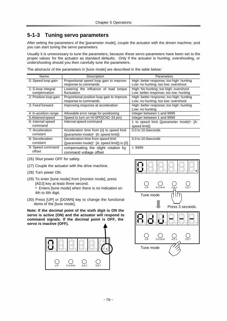
Chapter 5 Operations
- 76 -
5-1-3 Tuning servo parameters
After setting the parameters of the [parameter mode], couple the actuator with the driven machine; and you can start tuning the servo parameters.
Usually it is unnecessary to tune the parameters, because these servo parameters have been set to the proper values for the actuator as standard defaults. Only if the actuator is hunting, overshooting, or undershooting should you then carefully tune the parameters.
The abstracts of the parameters in [tune mode] are described in the table below:
Name Description Parameters 0: Speed loop gain Proportional speed loop gain to improve
response to commands High: better response; too high: hunting Low: no hunting; too low: overshoot
1: S-loop integral compensation
Lowering the influence of load torque fluctuation
High: No hunting; too high: overshoot Low: better response; too low: hunting
2: Position loop gain Proportional position loop gain to improve response to commands
High: better response; too high: hunting Low: no hunting; too low: overshoot
3: Feed forward Improving response at acceleration High: better response; too high: hunting Low: no hunting
4: In-position range Allowable error range for positioning Integer between 1 and 9999 5:Attained speed Speed to turn on HI-SPD(CN2-33 pin) Integer between 1 and 9999 6: Internal speed
command Internal speed command 1 to speed limit ([parameter mode]→ [A:
speed limit]) 7: Acceleration
constant Acceleration time from [o] to speed limit ([parameter mode]→[A: speed limit])
0.0 to 10.0seconds
8: Deceleration constant
Deceleration time from speed limit ([parameter mode]→[A: speed limit]) to [0]
0.0 to 10.0seconds
9: Speed command offset
compensating the slight rotation by command voltage offset
±9999
(26) Shut power OFF for safety.
(27) Couple the actuator with the drive machine.
(28) Turn power ON.
(29) To enter [tune mode] from [monitor mode], press [ADJ] key at least three second. ⇒Enters [tune mode] when there is no indication on 4th to 6th digit.
(30) Press [UP] or [DOWN] key to change the functional items of the [tune mode].
Note: If the decimal point of the sixth digit is ON the servo is active (ON) and the actuator will respond to command signals. If the decimal point is OFF, the servo is inactive (OFF).
A D J
D O W N U P A D J S E T
D O W N U P S E T
Tune mode
Press 3 seconds.
Tune mode
A D J D O W N U P S E T

Chapter 5 Operations
- 77 -
(31) To change a value, press the [ADJ] key at least 0.1 second. ⇒The first digit [0] flashes. You can change the value.
(32) Change the value with the [UP] key and the [DOWN] key. The [UP] key increases the value. The [DOWN] key decreases the value.
(33) To define the new value, press the [SET] key at least 0.1 second. ⇒The value is stored in the memory. From now on, the new value is effective.
(34) To cancel the changing operation and to make the previous value effective before, press the [ADJ] key at least 0.1 second. ⇒The previous value is restored.
(35) To terminate the [tune mode] and to return to the [monitor mode], press the [SET] while the [End] is indicated. ⇒ The indication mode then returns to the [monitor mode].
5-1-4 End of test run When above operations are finished, terminate the test run.
(36) Shut the power (OFF).
D O W N U P A D J S E T
Changing
While the first digit code flashes, it is able to change value.
D O W N U P A D J S E T
Press 0.1 sec.
D O W N U P A D J S E T
Setting new value
D O W N U P A D J S E T
To previous value
Press 0.1 sec.Press 0.1 sec.
D O W N U P A D J S E T
Tune mode
Monitor mode

Chapter 5 Operations
- 78 -
5-2 Usual operation As the HA-655 driver runs by commands from a host, no special intervention is required for normal operations. In this section, instructions for daily operations and maintenance are explained.
5-2-1 Notices for daily operations
5-2-2 Daily maintenance Since the HA-655 driver employs highly reliable parts, no special daily maintenance is required except the maintenance under user’s rules for electronic equipment.
Check point Interval Inspection standard Treatment
Terminal screws Yearly No loosen screws Tightening screws Exterior Yearly No dust or metal chips on the case Cleaning
Interior Circuitry Yearly No color change, no faults, no abnormalities
Consult with Harmonic drive systems
1. Shut down electric power before maintenance.
Maintenance while power is active may cause electric shock.
3. Do not touch terminals for at least five minutes after power-OFFstage.
Even with power-OFF, electric charge remains in the driver. Do not touch terminals at least five minutes after power-OFF to avoid electric shock.
3. Do not perform insulation resistance or high voltage breakdown tests.
The test causes damage to the HA -655 driver circuit that results in abnormal motion.
CAUTION
1. Do not make any wiring while power is active. Disconnecting wires or connectors while power is active may cause electric shock or abnormal mechanical motion resulting in serious physical injury.
2. Do not touch terminals for at least five minutes after power has been shut off [POWER OFF].
Even during power-OFF, electric charge remains in the driver. Do not touch terminals at least five minutes from power-OFF to avoid electric shock.
2. Do not operate drivers with frequent ON/OFF operation.
Frequent power ON/OFF operation may cause deterioration of electronic elements.Start / stop operation should be performed by using input signals.
CAUTION

Chapter 6 Setting up parameters
- 79 -
Chapter 6 Setting up parameters The display panel of the HA-655 driver is equipped with a six-digit LED display and four operation keys. Monitoring information, tuning operations, setting operations, and jog operation are done using the display panel.
6-1 Summary of modes The HA-655 driver provides the following four modes of monitor, tuning, parameter, and test:
Monitor mode
The HA-655 driver indicates position and speed commands, current position information from a motor-encoder, pulse count in an error counter, input and output signal states, load condition, alarm history, and the code number of the actuator. These are useful to diagnose the driver if it fails or operates in an abnormal manner.
After power ON sequence is complete, the [monitor mode] starts up. While the power is active, the monitor mode functions as the main screen switching from and to other modes.
Tuning mode
The tuning mode provides various parameters to control the actuator motion. Setting the most suitable value for each parameter obtains the optimum performances of the actuator.
Parameter mode
The parameter mode sets various parameter values relating to the fundamental operational functions such as: specifications of the position mode or the speed mode, configurations of input signals, an electronic gear function, limiting values of speed and torque, and parameters to communicate with a host.
Test mode
The test mode consists of required functions for system test, such as: JOG operation functions, operations of pseudo output signals, and I/O signal monitors.
6-2 Selecting a mode
After turning on the power, the [monitor mode] starts up automatically. The [ADJ] key and [SET] key select a mode.
Powering
Monitor mode
Parameter mode Tune mode Test mode
ADJ
3 sec. 3 sec.
ADJ SET SET
3 sec.
SET

Chapter 6 Setting up parameters
- 80 -
6-3 Functions of modes Each mode provides the following functions of position mode and speed mode individually.
Mode Code Position mode Setting Code Speed mode Setting 0 Error counter state 0 Error counter state 1 Motor revolutions 1 Motor revolutions 2 ――― 2 Speed command voltage 3 Error pulse count (Low) 3 Error pulse count (Low) 4 Error pulse count (High) 4 Error pulse count (High) 5 Torque monitor 5 Torque monitor 6 Overload rate 6 Overload rate 7 Feedback pulse (Low) 7 Feedback pulse (Low) 8 Feedback pulse (High) 8 Feedback pulse (High) 9 Command pulse (Low) 9 ――― A Command pulse (High) A ――― b Command pulse frequency b ――― c I/O monitor c I/O monitor d Alarm history d Alarm history E Actuator code E Actuator code
Mon
itor
mod
e
F Serial number
Impossible
F Serial number
Impossible
0 Speed loop gain 0 Speed loop gain 1 S-loop integral compensation 1 S-loop integral compensation 2 Position loop gain 2 Position loop gain
Possible
3 Feed-forward gain 3 ――― ――― 4 In-position range
Possible
4 ――― ――― 5 ――― ――― 5 Attained speed 6 ――― ――― 6 Internal speed command 7 ――― ――― 7 Acceleration time constant 8 ――― ――― 8 Deceleration time constant
Tun
e m
ode
9 ――― ――― 9 Speed command offset
Possible
0 Control mode 0 Control mode Possible 1 Command configuration 1 ――― ――― 2 Multiplication of 2-phase pulse 2 ――― ――― 3 Electronic gear - denominator 3 ――― ――― 4 Electronic gear - numerator 4 ――― ――― 5 Error count cleared by S-ON 5 ――― ――― 6 Position error allowance
Possible
6 ――― ――― 7 ――― ――― 7 Zero clamp 8 Rotary direction 8 Rotary direction 9 Speed conversion factor 9 Speed conversion factor A Speed limit A Speed limit b Torque limit b Torque limit c Alarm logic
Possible
c Alarm logic
Possible
d ――― ――― d ――― ――― E ――― ――― E ――― ―――
Par
amet
er m
ode
F * ABS multi-turn data clear Impossible F * ABS multi-turn data clear Impossible Jo JOG operation Possible Jo JOG operation Possible SP JOG speed SP JOG speed Ac JOG acceleration
Possible Ac JOG acceleration
Possible
InP Output port operation Possible InP Output port operation Possible c I/O monitor Impossible c I/O monitor Impossible
An Analog monitor manual output Possible An Analog monitor manual output Possible Test
mod
e
So Speed command auto-offset Possible So Speed command auto-offset Possible

Chapter 6 Setting up parameters
- 81 -
6-4 Monitor mode The HA-655 driver indicates position and speed commands, current position information from a motor-encoder, pulse count in an error counter, input and output signal states, load condition, alarm history, and the code number of the actuator. These are useful to diagnose the driver if it fails or operates in an abnormal manner.
After powering, the [monitor mode] starts up. While the power is on, from the monitor mode as the main screen, it is possible to switch to and from other modes.
The monitor mode indicates the following items.
Mode Code Position mode Setting Code Speed mode Setting 0 Error counter state 0 Error counter state 1 Motor revolutions 1 Motor revolutions 2 ――― 2 Speed command voltage 3 Error pulse count (Low) 3 Error pulse count (Low) 4 Error pulse count (High) 4 Error pulse count (High) 5 Torque monitor 5 Torque monitor 6 Overload rate 6 Overload rate 7 Feedback pulse (Low) 7 Feedback pulse (Low) 8 Feedback pulse (High) 8 Feedback pulse (High) 9 Command pulse (Low) 9 ――― A Command pulse (High) A ――― b Command pulse frequency b ――― c I/O monitor c I/O monitor d Alarm history d Alarm history E Actuator code E Actuator code
Mon
itor
mod
e
F ―――
Impossible
F ―――
Impossible
6-4-1 Operating in the monitor mode After powering or finishing operations in other modes, the drive automatically transfers to the [monitor mode]. Therefore, there is no special code for the [monitor mode].
Operation procedure
(1) To transfer to the [monitor mode] from other modes, press the [SET] key after displaying the [END]. ⇒ The monitor mode begins.
(2) Press the [UP] key or the [DOWN] key to change the functional items of the monitor mode. ⇒ Every pressing the [UP] key shifts a code of the first digit one by one from [0] to [E], and indicates a value corresponding to the code.
⇒ Every pressing the [DOWN] key shifts a code of the first digit one by one from [E] to [0], and indicates a value corresponding to the code.
Details of display
1st digit: Codes in the mode. Decimal point of the sixth digit:
When the point is on, the servo is active (ON) and the actuator is able to respond to a command signal. When the point is off, the servo is inactive (OFF).
D O W N U P A D J S E T
D O W N U P A D J S E T
Other modes
Monitor mode
1st digit 6th digit
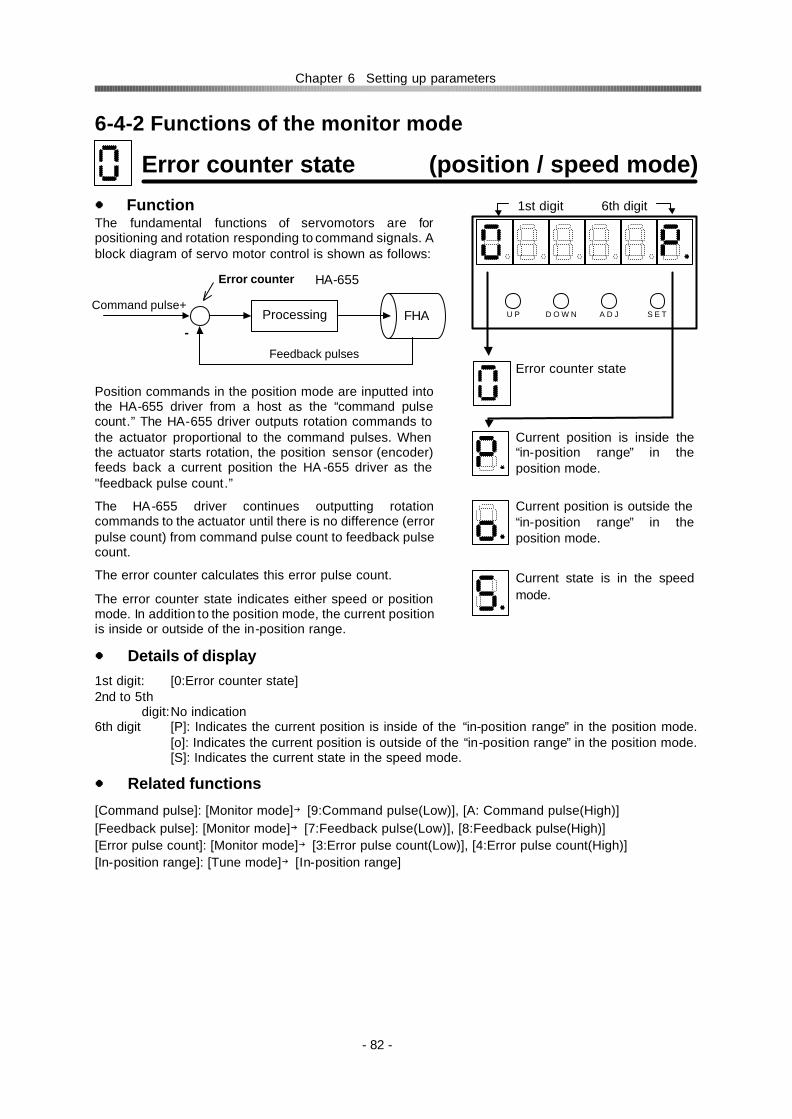
Chapter 6 Setting up parameters
- 82 -
6-4-2 Functions of the monitor mode
Error counter state (position / speed mode) Function The fundamental functions of servomotors are for positioning and rotation responding to command signals. A block diagram of servo motor control is shown as follows: Position commands in the position mode are inputted into the HA-655 driver from a host as the “command pulse count.” The HA-655 driver outputs rotation commands to the actuator proportional to the command pulses. When the actuator starts rotation, the position sensor (encoder) feeds back a current position the HA -655 driver as the "feedback pulse count.”
The HA-655 driver continues outputting rotation commands to the actuator until there is no difference (error pulse count) from command pulse count to feedback pulse count.
The error counter calculates this error pulse count.
The error counter state indicates either speed or position mode. In addition to the position mode, the current position is inside or outside of the in-position range.
Details of display 1st digit: [0:Error counter state] 2nd to 5th
digit: No indication 6th digit [P]: Indicates the current position is inside of the “in-position range” in the position mode.
[o]: Indicates the current position is outside of the “in-position range” in the position mode. [S]: Indicates the current state in the speed mode.
Related functions
[Command pulse]: [Monitor mode]→[9:Command pulse(Low)], [A: Command pulse(High)] [Feedback pulse]: [Monitor mode]→[7:Feedback pulse(Low)], [8:Feedback pulse(High)] [Error pulse count]: [Monitor mode]→[3:Error pulse count(Low)], [4:Error pulse count(High)] [In-position range]: [Tune mode]→[In-position range]
HA-655
Command pulse+Processing FHA
Feedback pulses
-
Error counter
D O W N U P A D J S E T
Error counter state
Current position is inside the “in-position range” in the position mode.
Current position is outside the “in-position range” in the position mode.
Current state is in the speed mode.
1st digit 6th digit
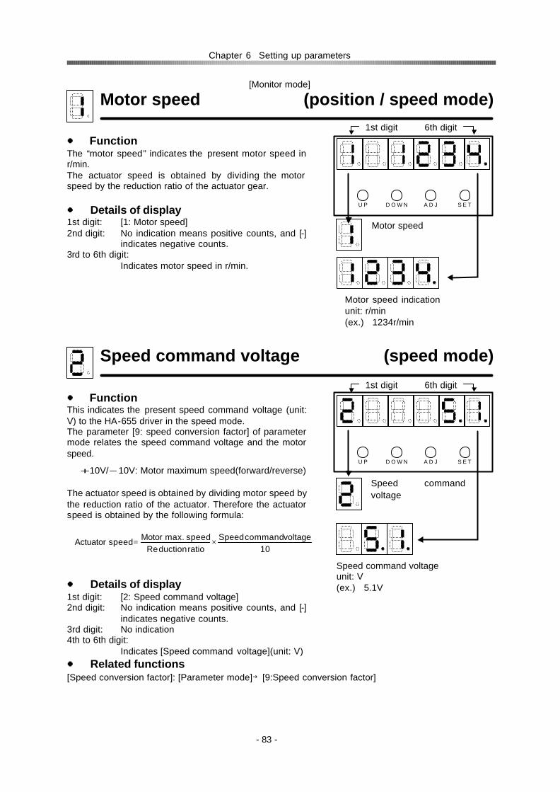
Chapter 6 Setting up parameters
- 83 -
[Monitor mode]
Motor speed (position / speed mode) Function The “motor speed” indicates the present motor speed in r/min. The actuator speed is obtained by dividing the motor speed by the reduction ratio of the actuator gear.
Details of display 1st digit: [1: Motor speed] 2nd digit: No indication means positive counts, and [-]
indicates negative counts. 3rd to 6th digit:
Indicates motor speed in r/min.
Speed command voltage (speed mode) Function This indicates the present speed command voltage (unit: V) to the HA-655 driver in the speed mode. The parameter [9: speed conversion factor] of parameter mode relates the speed command voltage and the motor speed.
+10V/-10V: Motor maximum speed(forward/reverse)
The actuator speed is obtained by dividing motor speed by the reduction ratio of the actuator. Therefore the actuator speed is obtained by the following formula:
Details of display 1st digit: [2: Speed command voltage] 2nd digit: No indication means positive counts, and [-]
indicates negative counts. 3rd digit: No indication 4th to 6th digit:
Indicates [Speed command voltage](unit: V) Related functions [Speed conversion factor]: [Parameter mode]→[9:Speed conversion factor]
D O W N U P A D J S E T
Motor speed indicationunit: r/min (ex.) 1234r/min
Motor speed
10voltagecommandSpeed
ratioductionRespeed.maxMotorspeedActuator ×=
1st digit 6th digit
D O W N U P A D J S E T
Speed command voltage unit: V (ex.) 5.1V
Speed command voltage
1st digit 6th digit

Chapter 6 Setting up parameters
- 84 -
[Monitor mode]
Error pulse count (low) (position / speed mode) Function The fundamental functions of servomotors are for positioning and rotation responding to a command signals. A block diagram of servo motor control is shown as follows: Position commands in the position mode are input into the HA-655 driver from a host as the “command pulse count.” The HA-655 driver outputs rotation commands to the actuator proportioning to the command pulses. When the actuator starts rotation, the position sensor (encoder) feeds back a current position into the HA-655 driver as the "feedback pulse count.”
The HA-655 driver continues outputting rotation commands to the actuator until there is no difference (error pulse count) from "command pulse count" to "feedback pulse count.”
This indicates the lower part of the current error pulse count.
Details of display
1st digit: [3: error pulse count (low)] 2nd digit: No indication means positive counts, and [-] indicates negative counts. 3rd to 6th digit: Indicates current quadrate error pulse counts in pulse unit.
Related functions
[Command pulse]: [Monitor mode]→[9: Command pulse (Low)], [A: Command pulse (High)] [Feedback pulse]: [Monitor mode]→[7: Feedback pulse (Low)], [8: Feedback pulse (Low)] [Error counter state]: [Monitor mode]→[0:Error counter state]
Error pulse count (high) (position / speed mode) Function This indicates the high part of an error quadrate pulse count. Combining with the [4:error pulse count (high)], the whole quadrate error pulse count is indicated. Details of display
1st digit: [4: error pulse count (high)] 2nd digit: No indication means positive counts, and [-]
indicates negative counts. 3rd to 6th digit: Indicates current quadrate error pulse
counts in pulse unit.
HA-655
Command pulse+Processing FHA
Feedback pulses
-
Error counter
D O W N U P A D J S E T
Error pulse count (low)
Current quadrate error pulse counts Unit: pulse (ex.) Quadrate error pulse = 8
1st digit 6th digit
D O W N U P A D J S E T
Error pulse count (high)
1st digit 6th digit

Chapter 6 Setting up parameters
- 85 -
[Monitor mode]
Torque Monitor (position / speed mode) Function This indicates current output torque of the actuator in “%” where “100%” corresponds to the maximum torque. Details of display 1st digit: [5: Torque monitor] 2nd digit: No indication means positive counts, and [-]
indicates negative counts. 3rd digit: No indication 4th to 6th digit: Indicates current output torque in “%”
where “100%” corresponds to the maximum torque.
Overload rate (position / speed mode) Function This indicates current overload rate of the actuator in “%.” The rate is determined by the overload protection characteristics of the motor. If the value reaches [100], the overload protection function shuts off the motor current, and issues an [Alarm 20].
Details of display 1st digit: [6: Overload rate] 2nd to 3rd digit: No indication 4th to 6th digit: Indicates the current [overload rate] in “%”
where “100%” is equal to the [overload protection characteristics] of the motor.
D O W N U P A D J S E T
Torque monitor
Current output torque where “100%” corresponds to the maximum torque Unit: % (ex.) Torque = 20%
1st digit 6th digit
D O W N U P A D J S E T
Overload rate
The current overload rate where “100%” is equal to the [overload protection characteristics] of the motor. Unit: % (ex.) Overload rate=20%
1st digit 6th digit

Chapter 6 Setting up parameters
- 86 -
[Monitor mode]
Feedback pulse (Low) (position / speed mode) Function The fundamental functions of servomotors are positioning and rotation responding to a command signal. A block diagram of servo motor control is shown as follows: [Feedback pulse] indicates a feedback quadrate pulse count (accumulated) that is reset to [0] position when the HA-655 driver is powered. As the count will become a large number, the count is divided in two parts: low 4th digit part and high part (up to 4th digits). [7: Feedback pulse (Low)] indicates the low part, and [8:feedback pulse (high)] indicates the high part. Details of display 1st digit: [7: Feedback pulse (Low)] 2nd digit: no indication: positive (forward) position, [-]: negative (reverse) position 3rd to 6th digit: Indicates a feedback quadrate pulse count (accumulated) that is reset to the [0] position
when the HA-655 driver powered.
Feedback pulse (High) (position / speed mode) Function This indicates the high part of a feedback quadrate pulse count (accumulated). Combining with the [6:feddback pulse (Low)], the whole pulse count is indicated. The high part of the example is “1932” and the low part “8930”, therefore the feedback quadrate count is “19328930.” Details of display
Same as [7: feedback pulse (Low)]
Related functions [Command pulse]: [Monitor mode]→[9: Command pulse
(Low)], [A: Command pulse (High)] [Error pulse count]: [Monitor mode]→[3:Error pulse count
(Low)], [4:Error pulse count (High)]
D O W N U P A D J S E T
[Feedback pulse (High)]
High part of feedback quadrate pulse count Unit: 4 times of feedback pulse (ex.) High part of feedback quadrate
pulses = 1932
HA-655
Command pulse+Processing FHA
Feedback pulses
-
Error counter
D O W N U P A D J S E T
Feedback pulse (Low)
Low 4th digit part of feedback quadrate pulse count Unit: 4 times of feedback pulse (ex.) Low 4th digit part of feedback
quadrate pulses = 8930
1st digit 6th digit
1st digit 6th digit

Chapter 6 Setting up parameters
- 87 -
[Monitor mode]
Command pulse (Low) (position mode) Function
The fundamental functions of servomotors are for positioning and rotation responding to a command signal. A block diagram of servo motor control is shown as follows: Position commands in the position mode are inputted into The HA-655 driver from a host as the command pulse count. The command is accumulated from the time of powering. As the count will become a large number, the count is divided in two parts: low 4th digit part and high part (up to 4th digits). [9: Command pulse (low)] indicates the low part, and [A: Command pulse (high)] indicates the high part. Details of display 1st digit: [9: Command pulse (Low)] 2nd digit: no indication: positive (forward) position, [-]: negative (reverse) position 3rd to 6th digit: Indicates a command count (accumulated) that is reset to the [0] position when the
HA-655 driver is powered.
Command pulse (High) (position mode) Function This indicates the high part of the command pulse count (accumulated). Combining with the [9: command pulse (Low)], the whole pulse count is indicated. The high part of the example is “31” and the low part “6802”, therefore the feedback quadrate count is “316802.”
Details of display
Same as [9: command pulse (Low)]
Related functions
[Feedback pulse]: [Monitor mode]→[7: Feedback pulse (Low)], [8: Feedback pulse (High)]
[Error pulse count]: [Monitor mode]→[3:Error pulse count (Low)], [4:Error pulse count (High)]
HA-655 D O W N U P A D J S E T
Command pulse (Low)
Low 4th digit part of command pulse count Unit: pulse (accumulated) (ex.) Low 4th digit part of command
pulses = 6802
D O W N U P A D J S E T
[Command pulse (High)
High part of command pulse count Unit: pulse (ex.) High part of
command pulses = 31
Command pulse+Processing FHA
Feedback pulses
-
Error counter
1st digit 6th digit
1st digit 6th digit

Chapter 6 Setting up parameters
- 88 -
[Monitor mode]
Command pulse frequency (position mode) Function
The fundamental functions of the servomotors are for positioning and rotation responding to a command signal. A block diagram of servo motor control is shown as follows: Position commands in the position mode are inputted into [CN2 26-30] pin of the HA-655 driver from a host as the “command pulse count.”
The monitor indicates the command pulse frequency in kp/s unit. The limit of the frequency is as follows:
Line driver command: 500 kp/s
Open collector command: 200 kp/s
Note: The maximum actuator speed limits the frequency also.
Details of display 1st digit: [b: Command pulse frequency] 2nd digit: No indication 3rd to 6th digit: Command pulse frequency (unit: kp/s) Related functions [Command pulse]: [Monitor mode]→[9: Command pulse (Low)], [A: Command pulse (High)]
HA-655
D O W N U P A D J S E T
Command pulse frequency
Command pulse frequency Unit: kp/s (ex.) Command pulse frequency
= 30kp/s
Command pulse+Processing FHA
Feedback pulses
-
Error counter
1st digit 6th digit

Chapter 6 Setting up parameters
- 89 -
[Monitor mode]
I/O monitor (position / speed mode) Function
The display indicates input/output signal states of [CN2] connector pins as follows:
Output signals: Forth digit Input signals: Sixth digit
Each element of both 7-segment indicators lights up when the related signal is input or output.
The indications are limited only for logical signals, not for encoder signals. Details of display 1st digit: [c:I/O monitor] 2nd digit: No indication 3rd to 4th digit: Indicates output signal states 5th digit: No indication 6th digit: Indicates input signal states
D O W N U P A D J S E T
I/O monitor
Output Input
1st digit 6th digit
for outputs CN2-33: In-position (pos. mode) Attained speed (spd. mode)
CN2-40: Alarm code C
CN2-34: Alarm
CN2-38: Alarm code A
CN2-37: Ready
CN2-39: Alarm code B
CN2-41: Alarm
code D
CN2-42: Phase-Z
4th digit 3rd digit
CN2-3: Servo-ON
for inputs CN2-2: Cleared
CN2-4: FWD inhibit(pos. mode)FWD enable(spd. mode)
CN2-5: REVinhibit(pos. mode) REV enable(spd. mode)
CN2-6: Command
change (spd. mode)
4th digit

Chapter 6 Setting up parameters
- 90 -
[Monitor mode]
Alarm history (position / speed mode) Function The “alarm history” indicates up to eight previous alarms with codes. Details of display 1st digit: [d: alarm history] 2nd digit: The order of the indicated alarm:
[1] indicates the latest alarm, and [8] indicates the earliest one.
3rd to 4th digit: No indication 5th to 6th digit: Indicates an alarm code.
Code Alarm description 10 Over speed 20 Over load 21 Overheat 30 Over current 41 Abnormal regeneration 50 Encoder failure 51 Abnormal encoder signal 52 UVW failure 53 *ABS system failure 54 *ABS MTD over flow 55 *ABS multi-turn data error 56 *ABS low battery voltage 57 *ABS send data rule error 60 Error counter overflow 70 Memory failure (RAM) 71 Memory failure (EEPROM) 76 CPU failure
Notice: the alarm codes 53rdrough 57 are valid for absolute encoders only.
Operations (1) To indicate earlier alarm codes, press the [UP] key.
⇒Every pressing the [UP] key increases the alarm-order on the second digit, and indicates the alarm code on the 5th to 6th digit corresponding to the alarm order. The alarm-order on the 2nd digit is limited to [8]. Pressing the [UP] key more is neglected.
(2) To indicate later alarm codes, press the [DOWN] key.
⇒Every pressing the [DOWN] key decreases the alarm-order on the second digit, and indicates the alarm code on the 5th to 6th digit corresponding to the alarm order. The alarm-order on the 2nd digit is limited to [1]. Pressing the [DOWN] key more is ignored or disregarded.
D O W N U P A D J S E T
Alarm history
UP: to earlier alarm DOWN: to later alarm
Alarm order: ordered later alarm to earlier.
[Alarm code]
1st digit 6th digit

Chapter 6 Setting up parameters
- 91 -
[Monitor mode]
Actuator code (position / speed mode) Function This indicates the code of the HA-655 driver is set for. The relation of the codes and actuators is as follows:
Encoder Incremental encoder Absolute encoder Reduction ratio 1/50 1/100 1/160 1/50 1/100 1/160
FHA-17C 5217 5237 5247 5218 5238 5248 FHA-25C 5417 5437 5447 5418 5438 5448 FHA-32C 5617 5637 5647 5618 5638 5648 FHA-40C 5717 5737 5747 5718 5738 5748
Note: The above table is available for 200V system only. Details of display 1st digit: [E: Actuator code] 2nd digit: No indication 3rd to 6th digit: Indicates an [Actuator code]. The relation of the codes and actuators is shown above.
D O W N U P A D J S E T
Actuator code
The actuator code of [5217] means that the actuator to be combined is FHA-17C-50 equipped an incremental encoder.
Do not connect an actuator that has another code than the indicated code. Wrong combinations of HA-655 drivers and actuators may cause low torque problems and over current that may cause physical injury and fire.
CAUTION
1st digit 6th digit

Chapter 6 Setting up parameters
- 92 -
6-5 Tune mode The tuning mode consists of various parameters to control the actuator motion. Setting the most suitable value for each parameter will ensure the optimum performance of the actuator.
The tune mode indicates and sets the following items.
Mode Code Position mode Setting Code Speed mode Setting 0 Speed loop gain 0 Speed loop gain 1 S-loop integral compensation 1 S-loop integral compensation 2 Position loop gain 2 Position loop gain
Possible
3 Feed-forward gain 3 ――― ――― 4 In-position range
Possible
4 ――― ――― 5 ――― ――― 5 Attained speed 6 ――― ――― 6 Internal speed command 7 ――― ――― 7 Acceleration time constant 8 ――― ――― 8 Deceleration time constant
Tun
e m
ode
9 ――― ――― 9 Speed command offset
Possible
6-5-1 Operating in the tune mode Selecting operations of function items
(1) To transfer to the tune mode from the monitor mode, press the [ADJ] key at least three seconds. ⇒ Transfers to the tune mode when there is no indication on 4th to 6th digit.
(2) Press the [UP] key or the [DOWN] key to change the functional items of the tune mode. ⇒ Every pressing the [UP] key shifts a code of the first digit one by one from [0] to [9], and indicates a value corresponding to the code. ⇒Every pressing the [DOWN] key shifts a code of the first digit one by one from [9] to [0], and indicates a value corresponding to the code.
Function
(1) Transferring to the tune mode: 1st to 3rd digit: Indicates [AdJ]. 4th to 6th digit: Indicates [-] throughout the transfer. (2) For the tune mode: 1st digit: Codes in the mode. Decimal point of the sixth digit:
If the decimal point of the sixth digit is ON, the servo is active (ON) and the actuator will respond to command signals. If the decimal point is OFF, the servo is inactive (OFF).
A D J
D O W N U P A D J S E T
D O W N U P S E T
Monitor mode
Press 3 seconds
Tune mode
A D J D O W N U P S E T
Selecting a function
1st digit 6th digit

Chapter 6 Setting up parameters
- 93 -
Operations of values
(1) To change a value, press the [ADJ] key at least 0.1 second. ⇒1st digit [0] flickers. You can change the value.
(2) Change the value with the keys of [UP] and [DOWN]. The [UP] key increases the value. The [DOWN] key decreases the value.
(3) To define the new value, press the [SET] key at least 0.1 second. ⇒The value is stored in the memory. From now on, the new value is effective.
(4) To cancel a change in operation and to make the previous value effective before defining, press the [ADJ] key at least 0.1 second. ⇒The previous value is restored.
D O W N U P A D J S E T
Changing
While 1st digit code flashes, you can change the value.
D O W N U P A D J S E T
Press 0.1 sec.
D O W N U P A D J S E T
Setting new value
D O W N U P A D J S E T
Canceling
Press 0.1 sec.Press 0.1 sec.
1st digit 6th digit

Chapter 6 Setting up parameters
- 94 -
6-5-2 Functions of the tune mode
Speed loop gain (position / speed mode) Function The HA-655 drivers make actuators follow command signals precisely by triple feedback loops of position, speed, and current. The [speed loop gain] adjusts the proportional gain of the speed feedback loop. The relation between the gain and actuator motion is as follows: High gain ⇒ obtains high servo stiffness and high
response. Excessive gain makes the servo system unstable, hunting, and a tendency to overshoot.
Low gain ⇒ Inadequate gain makes the servo system subject to undershooting.
Set the highest gain within the limits of no hunting, no overshooting nor undershooting by a step command.
Details of display 1st digit: [0: speed loop gain] 2nd to 6th digit: Indicates the current [speed loop gain]. An integer from [1] to [9999] can be set.
Operations (1) To change a value, press the [ADJ] key at least 0.1 second.
⇒1st digit [0] flashes. You can change the value. (2) If the actuator is hunting or takes a long time for its speed to settle after a step command, then
press the [DOWN] key to set a lower level. If the actuator takes a long time for its speed after a step command, then press the [UP] key to set a higher level.
(3) To define the new value, press the [SET] key at least 0.1 second. ⇒ Flashing of 1st digit [0] stops and the new value is defined.
(4) To cancel a change in operation, press the [ADJ] key at least 0.1 second. ⇒Flashing of 1st digit [0] stops and the previous value is restored.
Related functions [Speed loop integral compensation]: [tune mode]→[1: Speed loop integral compensation] [Position loop gain]: [tune mode]→[2:position loop gain] [Feed forward gain]: [tune mode]→[3:Feed forward gain]
D O W N U P A D J S E T
Speed loop gain
Indicates current speed loop gain.
Overshoot
Best
Undershoot
Speed
Time
1st digit 6th digit

Chapter 6 Setting up parameters
- 95 -
[Tune mode]
Speed loop integral compensation (pos./spd.) Function The HA-655 driver is equipped with a [Speed loop integral compensation] function to make speed fluctuation minimal against load torque variation. The relation between the gain and actuator motion is as follows: High gain ⇒ eliminates hunting and gives low response to
load torque variation. Low gain ⇒ high response to load torque variation,
excessive gain makes the servo system hunt.
Details of display 1st digit: [0:Speed loop integral compensation] 2nd to 6th digit: Indicates the current [Speed loop integral
compensation]. A value from [1] to [9999] can be set.
Operations (1) To change a value, press the [ADJ] key at least 0.1 second.
⇒1st digit [1] flashes. You can change the value. (2) When the actuator does hunting, press the [DOWN] key to set a lower value.
When the response is low to load torque variation, press the [UP] key to set a higher value. (3) To define the new value, press the [SET] key at least 0.1 second.
⇒ Flashing of 1st digit [1] stops and the new value is defined. (4) To cancel a change in operation, press the [ADJ] key at least 0.1 second.
⇒Flashing of 1st digit [1] stops and the previous value becomes effective. Related functions [Speed loop gain]: [tune mode]→[0:Speed loop gain] [Position loop gain]: [tune mode]→[2:position loop gain] [Feed forward gain]: [tune mode]→[3:Feed forward gain]
D O W N U P A D J S E T
Indicates the current the [speed loop integral compensation].
Speed loop integral compensation
1st digit 6th digit

Chapter 6 Setting up parameters
- 96 -
[Tune mode]
Position loop gain (position / speed mode) Function The HA-655 driver is equipped with triple feedback loops of position, speed and current to make actuator motion follow position command precisely. The [position loop gain] adjusts proportional gain of feedback loop gain. The relation between the gain and actuator motion is as follows: High gain ⇒ obtains small position and following error.
Excessive gain makes the servo system unstable and causes it to hunt.
Low gain ⇒ Inadequate gain results in a large following error to command signal.
Set the highest gain within the limits of no hunting, no overshooting nor undershooting by a step command. Details of display 1st digit: [2: position loop gain] 2nd to 6th digit: Indicates current [position loop gain]. A
value from [10] to [9999] can be set. Operations (1) To change a value, press the [ADJ] key at least 0.1 second.
⇒1st digit [2] flashes. You can change the value.
(2) When the actuator does hunting, press the [DOWN] key to set a lower value. When the position following a command is poor, press the [UP] key to set a higher value.
(3) To define a new value, press the [SET] key at least 0.1 second. ⇒ Flashing of 1st digit [2] stops and the new value is defined.
(4) To cancel a change in operation, press the [ADJ] key at least 0.1 second. ⇒Flashing of 1st digit [2] stops and the previous value becomes effective.
Related functions [Speed loop gain]: [tune mode]→[0:Speed loop gain] [Speed loop integral compensation]: [tune mode]→[1:Speed loop integral compensation] [Feed forward gain]: [tune mode]→[3:Feed forward gain]
D O W N U P A D J S E T
Position loop gain
Indicates the current [position loop gain]
1st digit 6th digit

Chapter 6 Setting up parameters
- 97 -
[Tune mode]
Feed forward gain (position mode) Function
In the position mode the HA-655 driver controls the error count, the difference between [command pulse] and [feedback pulse], to be [0]. At the beginning of inputting a command pulse train, the actuator starts slowly because of a of small error count.
The [feed forward] function may accelerate the actuator as much as possible, adding the speed commands to the speed control loop. The speed commands are converted from a command pulse frequency (feed forward rate = 100%). The feed forward function provides acceleration control, minimizing the position error. The effects of the feed forward are disabled when the feed forward rate equals 0%. The relation between the gain and actuator motion is as follows:
Excessive gain causes mechanical shock and hunting. Details of display
1st digit: [3:Feed forward gain] 2nd to 3rd digit: No indication 4th to 6th digit: indicates current [Feed forward gain]. A value from [0] to [100] can be set. Operations
(1) To change a value, press the [ADJ] key at least 0.1 second. ⇒1st digit [3] flashes. You can change the value.
(2) When the actuator does hunting or mechanical shock occurs, press the [DOWN] key and set a lower value. When the position following to command is poor, press the [UP] key to set a higher value.
(3) To define the new value, press the [SET] key at least 0.1 second. ⇒ Flashing of 1st digit [3] stops and the new value is defined.
(4) To cancel a change in operation, press the [ADJ] key at least 0.1 second. ⇒Flashing of 1st digit [3] stops and the previous value becomes effective.
Related functions
[Speed loop gain]: [tune mode]→[0:Speed loop gain] [Speed loop integral compensation]: [tune mode]→[1:Speed loop integral compensation] [Position loop gain]: [tune mode]→[2:Position loop gain]
HA-655
Command+ Position control
FHA
Feedback pulse
- Error pulse
Feed forward
D O W N U P A D J S E T
Feed forward
Feed forward rate unit:%
1st digit 6th digit

Chapter 6 Setting up parameters
- 98 -
[Tune mode]
In-position range (position mode) Function [In-position: INPOS (CN2-33 pin)] signal is outputted when an error count becomes less than the value of [in-position range]. The error count is the difference between [command pulse count] and [feedback pulse count],
Details of display 1st digit: [4: in-position range] 2nd digit: No indication 3rd to 6th digit: indicates the current [in-position range]. A
value from [0] to [9999] can be set.
Operations (1) To change a value, press the [ADJ] key at least 0.1
second. ⇒1st digit [4] flashes. You can change the value.
(2) To make [in-position range] narrow, press the [DOWN] key to set a lower value. To make it wide, press the [UP] key to set a higher value.
(3) To define the new value, press the [SET] key at least 0.1 second. ⇒ Flashing of 1st digit [4] stops and the new value is defined.
(4) To cancel a change in operation, press the [ADJ] key at least 0.1 second. ⇒Flashing of 1st digit [4] stops and the previous value becomes effective.
Attained speed (speed mode) Function [Attained speed: HISPD (CN2-33 pin)] signal is outputted when the actuator speed is more than the value of [attained speed].
Details of display 1st digit: [5:attained speed] 2nd digit: No indication 3rd to 6th digit: Indicates the current [attained speed]. A
value from [0] to [9999] can be set.
Operations (1) To change a value, press the [ADJ] key at least 0.1
second. ⇒1st digit [5] flashes. You can change the value.
(2) To make [attained speed] low, press the [DOWN] key to set a lower value. To make it high, press the [UP] key to set a higher value.
(3) To define the new value, press the [SET] key at least 0.1 second. ⇒ Flashing of 1st digit [5] stops and the new value is defined.
(4) To cancel a change in operation, press the [ADJ] key at least 0.1 second. ⇒Flashing of 1st digit [5] stops and the previous value becomes effective.
D O W N U P A D J S E T
In-position range
Indicates current [in-position range. Unit: pulse
1st digit 6th digit
D O W N U P A D J S E T
Attained speed
Indicates current [attained speed] Unit: r/min
1st digit 6th digit

Chapter 6 Setting up parameters
- 99 -
[Tune mode]
Internal speed command (speed mode) Function
The function can operate the actuator without an external command. This is convenient for test operations without hosts and for system diagnosis. Actuator motion at the interion speed starts with the input to [command change: CMD-CHG (CN2-6 pin)] and stops when input is OFF. Details of display 1st digit: [6: Internal speed command] 2nd digit: No indication 3rd to 6th digit: Indicates the current [internal speed
command] setting. Unit is r/min, and a value from [1] to [speed limit] can be set.
Operations (1) To change a value, press the [ADJ] key at least 0.1
second. ⇒1st digit [6] flashes. You can change the value.
(2) To make [internal speed command] lower, press the [DOWN] key to set a lower value. To make it high, press the [UP] key to set a higher value.
(3) To define the new value, press the [SET] key at least 0.1 second. ⇒ Flashing of 1st digit [6] stops and the new value is defined.
(4) To cancel a change in operation, press the [ADJ] key at least 0.1 second. ⇒Flashing of 1st digit [6] stops and the previous value becomes effective.
D O W N U P A D J S E T
Internal speed command
Indicates current [internal speed command]. Unit: r/min Range:1 to speed limit (Para.Mode A)
1st digit 6th digit

Chapter 6 Setting up parameters
- 100 -
[Tune mode]
Acceleration time constant (speed mode) Function [Acceleration time constant] is the time it takes to accelerate the motor from [0 r/min] to the speed of [A: speed limit] of [parameter mode]. The acceleration time to speed command voltage is as follows: Details of display 1st digit: [7: Acceleration time constant] 2nd to 3rd digit: No indication 4th to 6th digit: Indicates current [Acceleration time
constant], unit and a value from [0] to [9999] ms can be set.
Operations (1) To change a value, press the [ADJ] key at least 0.1
second. ⇒1st digit [7] flashes. You can change the value.
(2) To make [acceleration time constant] low, press the [DOWN] key to set a lower value. To make it higher, press the [UP] key to set a higher value.
(3) To define the new value, press the [SET] key at least 0.1 second. ⇒ Flashing of 1st digit [7] stops and the new value is defined.
(4) To cancel a change in operation, press the [ADJ] key at least 0.1 second. ⇒Flashing of 1st digit [7] stops and the previous value becomes effective.
Related functions [Speed limit]: [Parameter mode]→[A:Speed limit] [Speed conversion factor]: [Parameter mode]→[9:Speed conversion factor]
Deceleration time constant (speed mode)
Function [Deceleration time constant] is the time it takes to decelerate the motor from the speed of [A: speed limit] of [parameter mode] to [0 r/min]. The deceleration time to speed command voltage is as follows: Details of display 1st digit: [8: Deceleration time constant] 2nd to 3rd digit: No indication 4th to 6th digit: Indicates current [Deceleration time
constant], unit and a value from [0] to [9999] ms can be set.
Operations Same operations as [acceleration time constant]
10factorconversion.Spd
itlimSpeedvoltage.Cmd.consttime.Acceltime.Accel ××=
10factorconversion.Spd
itlimSpeedvoltage.Cmd
.consttime.Deceltime.Decel ××=
D O W N U P A D J S E T
Acceleration time constant
Indicates current [acceleration time constant]. Unit: millisecond Range: 0 to 9999 ms
1st digit 6th digit
D O W N U P A D J S E T
Deceleration time constant
Indicates current [deceleration time constant]. Unit: millisecond Range: 9999 ms
1st digit 6th digit

Chapter 6 Setting up parameters
- 101 -
[Tune mode]
Speed command offset (speed mode) Function In the speed mode, motor may rotate slightly in spite of [0V] speed command voltage. This problem may occur when the speed command voltage has an offset of a few milli-volt. This function removes the slight rotation by the command voltage offset. Search for a proper offset value by inputting [0V] of command voltage not to rotate the motor that changes the value.
Details of display 1st digit: [9: Speed command offset] 2nd to 3rd digit: No indication 4th to 6th digit: Indicates current [Speed command offset]
[-9999] to [9999] can be set.
Operations (1) To change a value, press the [ADJ] key at least 0.1
second. ⇒1st digit [9] flashes. You can change the value.
(2) Set speed command voltage on [0V]. (3) Increase or decrease the [speed command offset] until the motor stops.
To increase it, press the [DOWN] key to set a lower value. To decrease it, press the [UP] key to set a higher value.
(4) To define the new value, press the [SET] key at least 0.1 second. ⇒ Flashing of 1st digit [9] stops and the new value is defined.
(5) To cancel a change in operation, press the [ADJ] key at least 0.1 second. ⇒Flashing of 1st digit [9] stops and the previous value becomes effective.
Related functions [Speed command auto. offset]: [Test mode]→[Speed command auto. offset]
End of tune mode Function This terminates the [tune mode] and returns to the [monitor mode]. Indicating [End] and pressing the [SET] key returns to the [monitor mode].
Details of display 1st to 3rd digit: No indication 4th to 6th digit: Indicates [End]
Operations (1) To terminate the [tune mode] and to return to the
[monitor mode], press the [SET] with the [End] indicated. ⇒ The indication mode returns to the [monitor mode].
D O W N U P A D J S E T
Tune mode
Monitor mode
D O W N U P A D J S E T
Speed command offset
Indicates current [Speed command offset]
Range: [-9999] to [9999]
1st digit 6th digit
1st digit 6th digit

Chapter 6 Setting up parameters
- 102 -
6-6 Parameter mode The [parameter mode] sets various parameter values relating to the fundamental operational functions such as: specifications of [position mode] or [speed mode], configurations of input signals, electronic gear function, limiting values of speed and torque, and parameters to communicate with a host.
The parameter mode indicates and sets the following items.
Mode Code Position mode Setting Code Speed mode Setting 0 Control mode 0 Control mode Possible 1 Command configuration 1 ――― ――― 2 Multiplication of 2-phase pulse 2 ――― ――― 3 Electronic gear - denominator 3 ――― ――― 4 Electronic gear - numerator 4 ――― ――― 5 Error count cleared by S-ON 5 ――― ――― 6 Position error allowance
Possible
6 ――― ――― 7 ――― ――― 7 Zero clamp 8 Rotary direction 8 Rotary direction 9 Speed conversion factor 9 Speed conversion factor A Speed limit A Speed limit b Torque limit b Torque limit c Alarm logic
Possible
c Alarm logic
Possible
d ――― ――― d ――― ――― E ――― ――― E ――― ―――
Par
amet
er m
ode
F ABS multi-turn data clear Impossible F ABS multi-turn data clear Impossible
6-6-1 Operating in the parameter mode Selecting operations of function items (1) To transfer to [parameter mode] from [monitor mode],
press both the [ADJ] key and the [SET] key at the same time at least three seconds.
⇒Transfers to [parameter mode] when there is no indication on 4th to 6th digit.
(Note): While [servo-ON: S-ON (CN2-3 pin)] signal is ON, changing to [parameter mode] turns the signal OFF and the system goes into the servo-OFF state.
(2) Press the [UP] key or the [DOWN] key to change the functional items of [parameter mode] ⇒ Every pressing the [UP] key shifts a code of the first digit one by one from [0] to [b], and indicates a value corresponding to the code. ⇒Every pressing the [DOWN] key shifts a code of the first digit one by one from [b] to [0], and indicates a value corresponding to the code.
Function
(1) Transferring to the parameter mode: 1st to 3rd digit: indicates [SyP]. 4th to 6th digit: Indicates [-] throughout the transfer. (2) For the parameter mode: 1st digit: Codes in the mode 2nd to 6th digit: A value of the code Decimal point of the second digit: indicates that the state is
in the parameter mode.
A D J
D O W N U P A D J S E T
D O W N U P S E T
Monitor mode
Press both 3 sec.
Parameter mode
A D J D O W N U P S E T
Selecting a function
1st digit 6th digit

Chapter 6 Setting up parameters
- 103 -
Operations of values
(1) To change a value, press the [ADJ] key at least 0.1 second. ⇒1st digit [0] flashes. You can change the value.
(2) Change the value with the keys of [UP] and [DOWN].
The [UP] key increases the value.
The [DOWN] key decreases the value.
(3) To define the new value, press the [SET] key at least 0.1 second.
⇒The value is stored in the memory. From now on, the new value is effective.
(4) To cancel a change in operation and to make the previous value effective before defining, press the [ADJ] key at least 0.1 second.
⇒The previous value becomes effective.
D O W N U P A D J S E T
Changing
While 1st digit code flashes, it is possible to change value.
D O W N U P A D J S E T
Press 0.1 sec.
D O W N U P A D J S E T
Setting new value
D O W N U P A D J S E T
Canceling
Press 0.1 sec.Press 0.1 sec.
1st digit 6th digit

Chapter 6 Setting up parameters
- 104 -
6-6-2 Functions of the parameter mode
Control mode (position / speed mode) Function The HA-655 driver can control the actuator in either the [position mode] or the [speed mode]. This function selects an operating mode.
In the position mode a command signal is composed of pulse trains, while in the speed mode it is composed of an analog voltage. Details of display 1st digit: [0:Control mode] 2nd to 5th digit: No indication 6th digit: [0]: position mode (factory default)
[1]: speed mode Operations (1) To change a value, press the [ADJ] key at least 0.1 second.
⇒1st digit [0] flashes. You can change the value.
(2) To set [position mode], set [0] by the [DOWN] key. To set [speed mode], set [1] by the [UP] key.
(3) To define the new value, press the [SET] key at least 0.1 second. ⇒ Flashing of 1st digit [0] stops and the new value is defined.
(4) To cancel a change in operation, press the [ADJ] key at least 0.1 second. ⇒Flashing of 1st digit [0] stops and the previous value becomes effective.
D O W N U P A D J S E T
Control mode
Position Speed
1st digit 6th digit

Chapter 6 Setting up parameters
- 105 -
[Parameter mode]
Command configuration (position mode)
Function Three types of command signals can be inputted to the HA-655 driver as follows:
Type 2-pulse train 1-pulse train 2-phase pulse Code 0 1 2
Com
man
d c
onfig
urat
ion
FWD CN2-27,28 Forward Pulse train Phase-A
REV CN2-29,30 Reverse Polarity Phase-B
Setting Factory default
Details of display 1st digit: [1: command configuration]. 2nd to 5th digit: No indication 6th digit: Indicates current [command configuration] code (refer above table).
Operations (1) To change a value, press the [ADJ] key at least 0.1 second.
⇒1st digit [1] flashes. You can change the value. (2) Set a code to [command configuration] with the [UP] or [DOWN] key. (3) To define the new value, press the [SET] key at least 0.1 second.
⇒ Flashing of 1st digit [1] stops and the new value is defined. (4) To cancel a change in operation, press the [ADJ] key at least 0.1 second.
⇒Flashing of 1st digit [1] stops and the previous value becomes effective.
Multiplication of 2-phase pulse (position mode)
Function When [command configuration] is set at [2-phase pulse], it is possible to make the motion command pulse count two or four times greater than the command pulse count.
1: Same as the command count 2: Two times the command count 4: Four times the command count
Details of display 1st digit: [2:Multiplication of 2-phase pulse] 2nd to 5th digit: No indication 6th digit: Indicates the current multiplier of
[multiplication of 2-phase pulse] function. [1], [2] and [4] are allowed.
Operations Same operations as [command configuration] described above
D O W N U P A D J S E T
Indicates current command configuration. 0: 2-pulse train 1: 1-pulse train 2: 2-pase pulse
Command configuration
D O W N U P A D J S E T
Multiplication of 2-phase pulse
Indicates current multiplier. (ex.) quadrature
FWD
Forward
Reverse
REV
FWD
REV
Forward
Reverse
FWD
REV
FWD
REV
90°
Forward
Reverse
90°
FWD
REV
FWD
REV
1st digit 6th digit
1st digit 6th digit

Chapter 6 Setting up parameters
- 106 -
[Parameter mode]
Electronic gear-denominator (position mode) Function
This is used in conjunction with [4: electronic gear-numerator] as an electronic gear function that is used when it is required to make a relationship between a displacement of the driven mechanism an integer number of command pulses.
The relation of [denominator/numerator] is as follows:
For rotary motion:
For linear motion:
Determine integers for both the denominator and the numerator.
Details of display 1st digit: [3: Electronic gear-denominator] 2nd to 4th digit: No indication 5th to 6th digit: Indicates the current [Electronic gear-denominator]. A value from [1] to [50] can be set.
Operations (1) To change a value, press the [ADJ] key at least 0.1 second.
⇒1st digit [3] flashes. You can change the value. (2) Set a value to [electronic gear-denominator] with the keys of [UP] and [DOWN]. (3) To define the new value, press the [SET] key at least 0.1 second.
⇒ Flashing of 1st digit [3] stops and the new value is defined. (4) To cancel a change in operation, press the [ADJ] key at least 0.1 second.
⇒Flashing of 1st digit [3] stops and the previous value becomes effective.
Electronic gear-numerator (position mode) Function This is used with [3: electronic gear-denominator] as electronic gear function. Refer [3: electronic gear-denominator] for the details.
D O W N U P A D J S E T
Electronic gear-denominator
Indicates current the [Electronic gear-denominator]. Range: 1-50
numerator-gearElectronicrdenominato-gear cElecteroni
3601resolutionActuator
mechanismofratioductionRepulseforntdisplacemeAngular ××=
numerator-gearElectronicrdenominato-gear cElecteroni
resolutionActuatormechanismofpitchFeeding
pulseforntdisplacemeLinear ×=
1st digit 6th digit
D O W N U P A D J S E T
Electronic gear-numerator
1st digit 6th digit
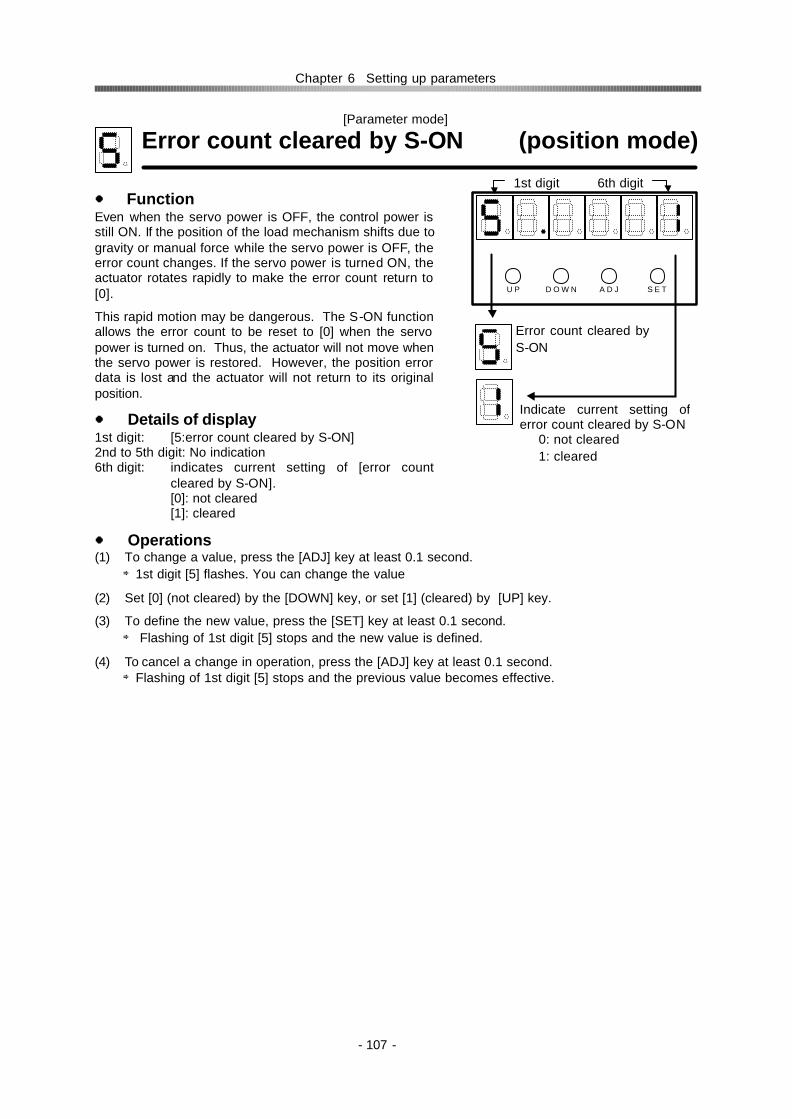
Chapter 6 Setting up parameters
- 107 -
[Parameter mode]
Error count cleared by S-ON (position mode) Function Even when the servo power is OFF, the control power is still ON. If the position of the load mechanism shifts due to gravity or manual force while the servo power is OFF, the error count changes. If the servo power is turned ON, the actuator rotates rapidly to make the error count return to [0].
This rapid motion may be dangerous. The S-ON function allows the error count to be reset to [0] when the servo power is turned on. Thus, the actuator will not move when the servo power is restored. However, the position error data is lost and the actuator will not return to its original position.
Details of display 1st digit: [5:error count cleared by S-ON] 2nd to 5th digit: No indication 6th digit: indicates current setting of [error count
cleared by S-ON]. [0]: not cleared [1]: cleared
Operations (1) To change a value, press the [ADJ] key at least 0.1 second.
⇒1st digit [5] flashes. You can change the value
(2) Set [0] (not cleared) by the [DOWN] key, or set [1] (cleared) by [UP] key.
(3) To define the new value, press the [SET] key at least 0.1 second. ⇒ Flashing of 1st digit [5] stops and the new value is defined.
(4) To cancel a change in operation, press the [ADJ] key at least 0.1 second. ⇒Flashing of 1st digit [5] stops and the previous value becomes effective.
D O W N U P A D J S E T
Error count cleared by S-ON
Indicate current setting of error count cleared by S-ON
0: not cleared 1: cleared
1st digit 6th digit

Chapter 6 Setting up parameters
- 108 -
[Parameter mode]
Position error allowance (position mode) Function The [error counter] calculates [error count] subtracting the [feedback count] from the [position command]. A large position error may result in an abnormality. When the position error exceeds the [position error allowance], an [alarm 60] occurs and the servo power shuts off.
Details of display 1st digit: [6: position error allowance] 2nd digit: No indication 3rd to 6th digit: Indicates the current [position error
allowance]. A value from [1] to [1000] can be set.
Operations (1) To change a value, press the [ADJ] key at least 0.1
second. ⇒1st digit [6] flashes. You can change the value.
(2) To make the allowance narrow, press the [DOWN] key. To make it wide, press the [UP] key.
(3) To define the new value, press the [SET] key at least 0.1 second. ⇒ Flashing of 1st digit [6] stops and the new value is defined.
(4) To cancel a change in operation, press the [ADJ] key at least 0.1 second. ⇒Flashing of 1st digit [6] stops and the previous value becomes effective.
Zero clamp (speed mode) Function In the speed mode when the [speed command] is [0], the actuator may rotate slightly by force from the drive mechanism. The [Zero clamp] function forcefully stops actuator when the speed command is [0]. Details of display 1st digit: [7: Zero clamp] 2nd to 5th digit: No indication 6th digit: Indicates current setting of [zero clamp]
function. [0]: Zero clamp OFF; [1]: Zero clamp ON
Operations (1) To change a value, press the [ADJ] key at least 0.1
second. ⇒1st digit [7] flashes. You can change the value.
(2) By the keys of [UP] and [DOWN], set [0] (no function) or [1] (zero clamp).
(3) To define the new value, press the [SET] key at least 0.1 second. ⇒ Flashing of 1st digit [7] stops and the new value is defined.
(4) To cancel a change in operation, press the [ADJ] key at least 0.1 second. ⇒Flashing of 1st digit [7] stops and the previous value becomes effective.
D O W N U P A D J S E T
Position error allowance
Indicates [position error allowanceRange: 1 to 1000 (x1000 pulses)
1st digit 6th digit
D O W N U P A D J S E T
Zero clamp
Indicates [zero clamp] setting 0: Zero clamp OFF 1: zero clamp ON
1st digit 6th digit
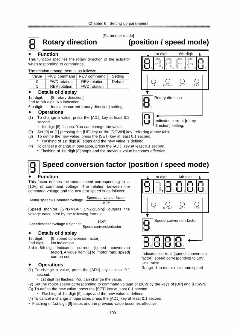
Chapter 6 Setting up parameters
- 109 -
[Parameter mode]
Rotary direction (position / speed mode)
Function This function specifies the rotary direction of the actuator when responding to commands.
The relation among them is as follows: Value FWD command REV command Setting
0 FWD rotation REV rotation Default 1 REV rotation FWD rotation
Details of display 1st digit: [8: rotary direction] 2nd to 5th digit: No indication 6th digit: Indicates current [rotary direction] setting. Operations (1) To change a value, press the [ADJ] key at least 0.1
second. ⇒1st digit [8] flashes. You can change the value.
(2) Set [0] or [1] pressing the [UP] key or the [DOWN] key, referring above table. (3) To define the new value, press the [SET] key at least 0.1 second.
⇒ Flashing of 1st digit [8] stops and the new value is defined. (4) To cancel a change in operation, press the [ADJ] key at least 0.1 second.
⇒Flashing of 1st digit [8] stops and the previous value becomes effective.
Speed conversion factor (position / speed mode)
Function This factor defines the motor speed corresponding to a [10V] of command voltage. The relation between the command voltage and the actuator speed is as follows: [Speed monitor (SPD-MON: CN2-23pin)] outputs the voltage calculated by the following formula: Details of display 1st digit: [9: speed conversion factor] 2nd digit: No indication 3rd to 6th digit: Indicates current [speed conversion
factor]. A value from [1] to [motor max. speed] can be set.
Operations (1) To change a value, press the [ADJ] key at least 0.1
second. ⇒1st digit [9] flashes. You can change the value.
(2) Set the motor speed corresponding to command voltage of [10V] by the keys of [UP] and [DOWN]. (3) To define the new value, press the [SET] key at least 0.1 second.
⇒ Flashing of 1st digit [9] stops and the new value is defined. (4) To cancel a change in operation, press the [ADJ] key at least 0.1 second. ⇒Flashing of 1st digit [9] stops and the previous value becomes effective.
D O W N U P A D J S E T
Rotary direction
Indicates current [rotary direction] setting.
10.0VfactorconversionSpeed
voltageCommandspeedMotor ×=
factorconversionSpeedSpeedvoltagemonitorSpeed
10.0V×=
1st digit 6th digit
D O W N U P A D J S E T
Speed conversion factor
Indicates current [speed conversion factor]: speed corresponding to 10V. Unit: r/min Range: 1 to motor maximum speed
1st digit 6th digit

Chapter 6 Setting up parameters
- 110 -
[Parameter mode]
Speed limit (position / speed mode)
Function This function limits motor speed to protect the motor and driven mechanism. Details of display 1st digit: [A: speed limit] 2nd digit: No indication 3rd to 6th digit: Indicates current [speed limit]. A value
from [1] to [motor max. speed] can be set.
Operations (1) To change a value, press the [ADJ] key at least 0.1
second. ⇒1st digit [A] flashes. You can change the value.
(2) Set a value to [speed limit] by the keys of [UP] and [DOWN].
(3) To define the new value, press the [SET] key at least 0.1 second. ⇒ Flashing of 1st digit [A] stops and the new value is defined.
(4) To cancel a change in operation, press the [ADJ] key at least 0.1 second. ⇒Flashing of 1st digit [A] stops and the previous value becomes effective.
Torque limit (position / speed mode) Function This function limits motor torque to protect the motor and driven mechanism. The maximum motor torque corresponds to 100%. Details of display 1st digit: [b:torque limit] 2nd to 3rd digit: No indication 4th to 6th digit: Indicates current [torque limit]. A value
from [1] to [100] can be set.
Operations (1) To change a value, press the [ADJ] key at least 0.1
second. ⇒1st digit [b] flashes. You can change the value.
(2) Set a value to [torque limit] with the keys of [UP] and [DOWN].
(3) To define the new value, press the [SET] key at least 0.1 second. ⇒ Flashing of 1st digit [b] stops and the new value is defined.
(4) To cancel a change in operation, press the [ADJ] key at least 0.1 second. ⇒Flashing of 1st digit [b] stops and the previous value becomes effective.
D O W N U P A D J S E T
Speed limit
Indicates [speed limit]. Unit: r/min Range: 1 to motor max. speed
1st digit 6th digit
D O W N U P A D J S E T
Torque limit
Indicates current torque limit; Range: 1 to 100%
1st digit 6th digit

Chapter 6 Setting up parameters
- 111 -
[Parameter mode]
Alarm logic (position / speed mode) Function The alarm signal logic (normal open / normal close) is defined as follows:
Value Logic Setting 0 Normal close (NC) Factory default 1 Normal open (NO)
Details of display 1st digit: [c: alarm logic] 2nd to 5th digit: No indication 6th digit: Indicates current [alarm logic] setting.
Operations (1) To change a value, press the [ADJ] key at least 0.1
second. ⇒1st digit [c] flashes. You can change the value.
(2) Set [0] or [1] with the keys of [UP] and [DOWN]. (3) To define the new value, press the [SET] key at least
0.1 second. ⇒ Flashing of 1st digit [c] stops and the new value is defined.
(4) To cancel a change in operation, press the [ADJ] key at least 0.1 second. ⇒Flashing of 1st digit [c] stops and the previous value becomes effective.
ABS multi-turn data clear (position / speed mode) Function This function clears data in the absolute multi-turn counter manually. Details of display 1st digit: [F: ABS multi-turn data clear] 2nd digit: No indication 3rd to 6th digit: Indicates time for absolute multi-turn
data clear.
Operations (1) To change a value, press the [ADJ] key at least 0.1
second. ⇒1st digit [F] flashes. You can change the value.
(2) Press the [SET] key, then [2500] is indicated. Keeping the pressing more the value decreases to [0]. Then [clr] will indicated.
(3) Press the [SET] key at least 0.1 second following the [clr] indication. ⇒ Flashing of 1st digit [F] stops and the ABS multi-turn data are cleared.
D O W N U P A D J S E T
Alarm logic
Indicates current [alarm logic] setting.
0: Normal close 1: Normal open
1st digit 6th digit
D O W N U P A D J S E T
ABS multi-turn data clear
Indicates time for absolute multi-turn data clear.
2500: default clr: cleared
1st digit 6th digit

Chapter 6 Setting up parameters
- 112 -
End of parameter mode Function This terminates the [parameter mode] and returns to the [monitor mode]. Indicating [End] and pressing the [SET] key returns you to the [monitor mode]. Details of display 1st to 3rd digit: No indication 4th to 6th digit: indicates [End].
Operations To terminate the [parameter mode] and to return to the [monitor mode], press the [SET] with [End] indicated. ⇒ The parameter mode returns to the [monitor mode].
D O W N U P A D J S E T
Parameter mode
Monitor mode
1st digit 6th digit
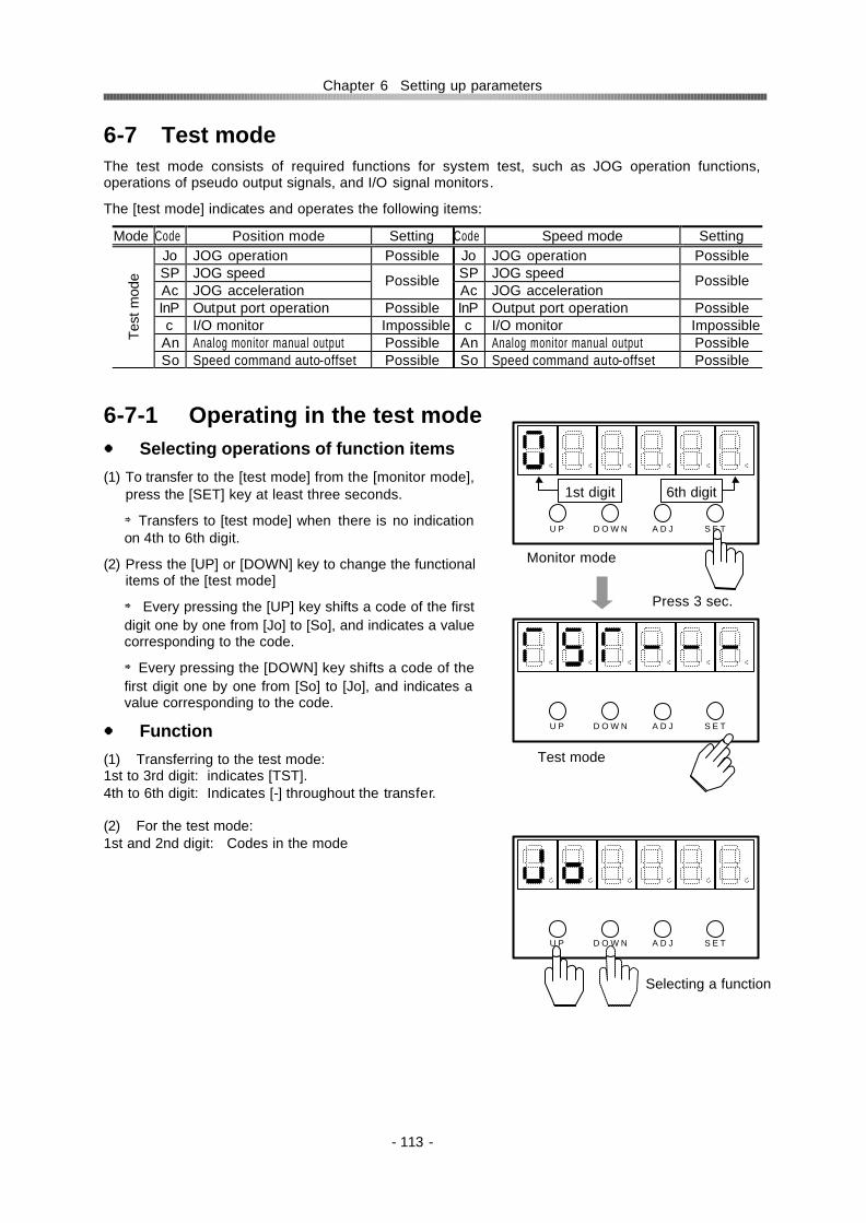
Chapter 6 Setting up parameters
- 113 -
6-7 Test mode The test mode consists of required functions for system test, such as JOG operation functions, operations of pseudo output signals, and I/O signal monitors.
The [test mode] indicates and operates the following items:
Mode Code Position mode Setting Code Speed mode Setting Jo JOG operation Possible Jo JOG operation Possible SP JOG speed SP JOG speed Ac JOG acceleration
Possible Ac JOG acceleration
Possible
InP Output port operation Possible InP Output port operation Possible c I/O monitor Impossible c I/O monitor Impossible
An Analog monitor manual output Possible An Analog monitor manual output Possible Test
mod
e
So Speed command auto-offset Possible So Speed command auto-offset Possible
6-7-1 Operating in the test mode Selecting operations of function items
(1) To transfer to the [test mode] from the [monitor mode], press the [SET] key at least three seconds.
⇒Transfers to [test mode] when there is no indication on 4th to 6th digit.
(2) Press the [UP] or [DOWN] key to change the functional items of the [test mode]
⇒ Every pressing the [UP] key shifts a code of the first digit one by one from [Jo] to [So], and indicates a value corresponding to the code.
⇒Every pressing the [DOWN] key shifts a code of the first digit one by one from [So] to [Jo], and indicates a value corresponding to the code.
Function
(1) Transferring to the test mode: 1st to 3rd digit: indicates [TST]. 4th to 6th digit: Indicates [-] throughout the transfer. (2) For the test mode: 1st and 2nd digit: Codes in the mode
A D J
D O W N U P A D J S E T
D O W N U P S E T
Monitor mode
Press 3 sec.
Test mode
A D J D O W N U P S E T
Selecting a function
1st digit 6th digit

Chapter 6 Setting up parameters
- 114 -
Operations
(1) To change a value, press the [ADJ] key at least 0.1 second. ⇒1st digit [0] flashes. You can change the value.
(2) Change the value with the keys of [UP] and [DOWN]. [UP] key increases the value. [DOWN] key decreases the value.
(3) To define the new value, press the [SET] key at least 0.1 second. ⇒The value is stored in the memory. From now on, the new value is effective.
(4) To cancel a change in operation and to make the previous value effective before defining, press the [ADJ] key at least 0.1 second. ⇒The previous value becomes effective.
D O W N U P A D J S E T
Changing
While 1st digit code flickers, it is possible to change value.
D O W N U P A D J S E T
Press 0.1 sec.
D O W N U P A D J S E T
Setting new value
D O W N U P A D J S E T
Canceling
Press 0.1 secPress 0.1 sec
1st digit 6th digit

Chapter 6 Setting up parameters
- 115 -
6-7-2 Functions of the test mode
JOG operation (position / speed mode) Function
Pressing [UP] or [DOWN] key rotates the motor with the speed of [1:JOG speed]. Details of display 1st and 2nd digit: [Jo: JOG operation] 3rd to 6th digit: No indication Operations (1) To transfer to in [JOG operation] mode, Press the
[ADJ] key at least 0.1 second. ⇒1st digit [J] flashes and servo turns ON. ⇒JOG operation is available.
(2) To operate the motor forward, press the [UP] key. ⇒The motor will rotate when the key is pressed, and will stop when the key is left.
(3) To operate the motor reverse, press the [DOWN] key. ⇒The motor will rotate when the key is pressed, and will stop when the key is released.
(4) To exit from [JOG operation] mode, press the [SET] key at least 0.1 second. ⇒ Flashing of 1st digit [J] stops, servo turns OFF, and [JOG operation] mode terminates.
Related functions [JOG speed]: [test mode]→[SP: JOG speed] [JOG acceleration]: [test mode]→[Ac: JOG acceleration]
Before JOG operation, make sure load conditions and motor/ encoder cable installations are correct. Activating JOG operation mode turns servo ON. Improper load and poor cable installation can result in accidents that may cause physical injury and fire.
CAUTION
D O W N U P A D J S E T
JOG operation
CW forward
CCW reverse
Turns on servo to operate the motor.
D O W N U P A D J S E T
D O W N U P A D J S E T
Turns servo OFF. [JOG operation] is unable.
1st digit 6th digit

Chapter 6 Setting up parameters
- 116 -
[Test mode]
JOG speed (position / speed mode) Function
The motor speed in [JOG operation] mode is set in [10r/min] increments. The unit is [r/min].
Details of display 1st and 2nd digit: [SP: JOG speed] 3rd to 6th digit: [JOG speed]; unit: r/min Operations (1) To set [JOG speed], press the [ADJ] key at least
0.1second. ⇒1st digit [S] flashes. You can change the value.
(2) To set [JOG speed] press the [UP] to increase the value, or [DOWN] key for decrease it.
(3) To define the new value, press the [SET] key at least 0.1 second. ⇒ Flashing of 1st digit [S] stops and the new value is defined.
(4) To cancel a change in operation, press the [ADJ] key at least 0.1 second. ⇒Flashing of 1st digit [S] stops and the previous value becomes effective.
JOG acceleration (position / speed mode)
Function The motor acceleration and deceleration in [JOG operation] mode is set by the accelerating time from [0] to [JOG speed] in [msec] unit.
Details of display 1st and 2nd digit: [Ac: JOG acceleration] 3rd to 6th digit: [JOG accelerating time]; unit: msec
Operations (1) To set [JOG acceleration], press the [ADJ] key at
least 0.1 second. ⇒1st digit [A] flashes. You can change the value.
(2) To set [JOG acceleration] press the [UP] to increase the value, or [DOWN] key for decrease it.
(3) To define the new value, press the [SET] key at least 0.1 second. ⇒ Flashing of 1st digit [A] stops and the new value is defined.
(4) To cancel a change in operation, press the [ADJ] key at least 0.1 second. ⇒Flashing of 1st digit [A] stops and the previous value becomes effective.
Related functions [JOG operation]: [test mode]→[Jo: JOG operation] [JOG speed]: [test mode]→[SP: JOG speed]
D O W N U P A D J S E T
JOG speed
Indicates current [JOG speed]. Unit: r/min; 10r/min step Range: 100 to motor max. speed
1st digit 6th digit
D O W N U P A D J S E T
JOG acceleration
Indicates current [JOG acceleration] Unit: msec
1st digit 6th digit

Chapter 6 Setting up parameters
- 117 -
[Test mode]
Output port operation (pos. / spd. mode) Function It is possible to operate turn (ON/OFF) output ports manually.
Details of display 1st to 3rd digit: indicates the code for the output port. 4th to 6th digit: indicates current state of the port.
Operations (1) To operate output ports, press the [ADJ] key at least
0.1 second.
⇒1st digit flashes. You can operate output ports. (Pressing the [ADJ] key at least 0.1 second again inhibits [output port operation].
(2) Press the [UP] key to specify an output port to be operated. ⇒Every pressing the key shifts the code number in the order of the figures to the right.
(3) Press the [DOWN] key to operate ON/OFF the selected. port. ⇒Every pressing the key alters the port state (ON→OFF→ON→).
(4) To terminate the output port operation, press the [SET] key at least 0.1 second. ⇒ Flashing of 1st digit stops and [output port operation] is inhibited.
D O W N U P A D J S E T
ON
OFF
In-position IN-POS: CN2-33
Attained speedHI-SPD: CN2-33
Alarm ALARM: CN2-34
Alarm-A ALARM: CN2-38
Alarm-B ALARM: CN2-39
Alarm-C ALARM: CN2-40
Alarm-D ALARM: CN2-41
D O W N U P A D J S E T
1st digit 6th digit

Chapter 6 Setting up parameters
- 118 -
[Test mode]
I/O port operation (position / speed mode) Function
The display indicates input/output signal states of [CN2] connector pins as follows:
Output signals: Fourth digit Input signals: Sixth digit
An element of the two 7-segment indicators light up when the related signal is input or output.
This function is limited only to logic signals; it is not available for the encoder signals. Details of display 1st digit: [c:I/O monitor] 2nd digit: No indication 3rd to 4th digit: Indicates output signal states 5th digit: No indication 6th digit: Indicates input signal states
D O W N U P A D J S E T
I/O monitor
Output Input
1st digit 6th digit
for outputs CN2-33: In-position (pos. mode) Attained speed (spd. mode)
CN2-40: Alarm code C
CN2-34: Alarm
CN2-38: Alarm code A
CN2-37: Ready
CN2-39: Alarm code B
CN2-41: Alarm
code D
CN2-42: Phase-Z
4th digit 3rd digit
CN2-3: Servo-ON
for inputs CN2-2: Cleared
CN2-4: FWD inhibit(pos. mode)FWD enable(spd. mode)
CN2-5: REVinhibit(pos. mode) REV enable(spd. mode)
CN2-6: Command
change (spd. mode)
4th digit

Chapter 6 Setting up parameters
- 119 -
[Test mode]
Analog monitor manual output (speed mode) Function
It is possible to output voltage signals manually through the monitor ports in the speed mode. Two analog ports are provided for monitoring.
Speed monitor: SPD-MON (CN2-23pin)
Current monitor: CUR-MON (CN2-24pin) Details of display 1st and 2nd digit: [An: analog monitor manual output] 3rd to 6th digit: indicates current output voltage. Operations (1) To transfer to in the [analog monitor manual output]
mode, press the [ADJ] key at least 0.1 second. ⇒1st digit [A] flashes now you can output voltage signals. (Pressing the [ADJ] key at least 0.1 second again inhibits the [analog monitor manual output].
(2) To output voltage from [speed monitor: SPD-MON (CN2-23pin)], press the [UP] key. ⇒While pressing, the pin continues to output varying voltage signal.
(3) To output voltage from [current monitor: CUR-MON (CN2-24pin)], press the [DOWN] key. ⇒While pressing, the pin continues to output varying voltage signal.
(4) To terminate [analog monitor manual output] operation, press the [SET] key at least 0.1 second. ⇒ Flashing of 1st digit stops and [analog monitor manual output] operation is inhibited.
D O W N U P A D J S E T
Analog monitor manual output
Indicates current output voltage Unit: 0.1V Range: -10V to +10V
1st digit 6th digit
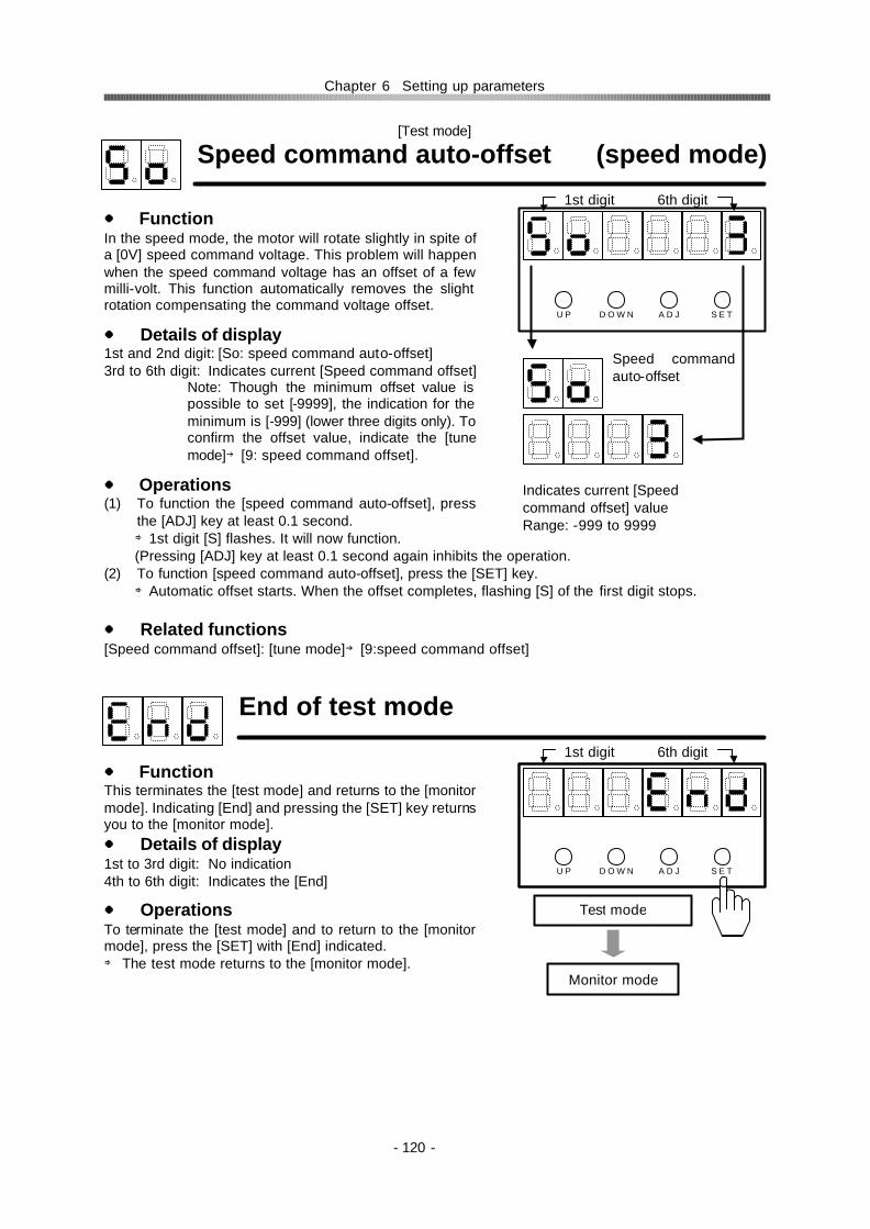
Chapter 6 Setting up parameters
- 120 -
[Test mode]
Speed command auto-offset (speed mode) Function In the speed mode, the motor will rotate slightly in spite of a [0V] speed command voltage. This problem will happen when the speed command voltage has an offset of a few milli-volt. This function automatically removes the slight rotation compensating the command voltage offset.
Details of display 1st and 2nd digit: [So: speed command auto-offset] 3rd to 6th digit: Indicates current [Speed command offset]
Note: Though the minimum offset value is possible to set [-9999], the indication for the minimum is [-999] (lower three digits only). To confirm the offset value, indicate the [tune mode]→[9: speed command offset].
Operations (1) To function the [speed command auto-offset], press
the [ADJ] key at least 0.1 second. ⇒1st digit [S] flashes. It will now function. (Pressing [ADJ] key at least 0.1 second again inhibits the operation.
(2) To function [speed command auto-offset], press the [SET] key. ⇒Automatic offset starts. When the offset completes, flashing [S] of the first digit stops.
Related functions [Speed command offset]: [tune mode]→[9:speed command offset]
End of test mode Function This terminates the [test mode] and returns to the [monitor mode]. Indicating [End] and pressing the [SET] key returns you to the [monitor mode]. Details of display 1st to 3rd digit: No indication 4th to 6th digit: Indicates the [End]
Operations To terminate the [test mode] and to return to the [monitor mode], press the [SET] with [End] indicated. ⇒ The test mode returns to the [monitor mode].
D O W N U P A D J S E T
Speed command auto-offset
Indicates current [Speed command offset] value Range: -999 to 9999
1st digit 6th digit
D O W N U P A D J S E T
Test mode
Monitor mode
1st digit 6th digit

Chapter 6 Setting up parameters
- 121 -
6-8 Defaults of parameters The following table shows the defaults of the parameters:
<< for incremental encoder system >> Actuator
FHA-17C FHA-25C FHA-32C FHA-40C
Mod
e
Code
Parameter 1/50 1/100 1/160 1/50 1/100 1/160 1/50 1/100 1/160 1/50 1/100 1/160
0 Speed loop gain 25 25 25 50 50 50 80 80 80 120 120 120 1 S-loop integral compensation 40 40 40 40 40 50 40 40 40 40 40 40 2 Position loop gain 40 40 40 40 40 40 40 40 40 40 40 40 3 Feed-forward gain 0 0 0 0 0 0 0 0 0 0 0 0 4 In-position range 10 10 10 10 10 10 10 10 10 10 10 10 5 Attained speed 2000 2000 2000 2000 2000 2000 2000 2000 2000 2000 2000 2000 6 Internal speed command 0 0 0 0 0 0 0 0 0 0 0 0 7 Acceleration time constant 0 0 0 0 0 0 0 0 0 0 0 0 8 Deceleration time constant 0 0 0 0 0 0 0 0 0 0 0 0
Tune
mod
e
9 Speed command offset - - - - - - - - - - - - 0 Control mode 0 0 0 0 0 0 0 0 0 0 0 0 1 Command configuration 0 0 0 0 0 0 0 0 0 0 0 0 2 Multiplication of 2-phase pulse 1 1 1 1 1 1 1 1 1 1 1 1 3 Electronic gear - denominator 1 1 1 1 1 1 1 1 1 1 1 1 4 Electronic gear - numerator 1 1 1 1 1 1 1 1 1 1 1 1 5 Error count cleared by S-ON 0 0 0 0 0 0 0 0 0 0 0 0 6 Position error allowance 100 100 100 100 100 100 100 100 100 100 100 100 7 Zero clamp 0 0 0 0 0 0 0 0 0 0 0 0 8 Rotary direction 0 0 0 0 0 0 0 0 0 0 0 0 9 Speed conversion factor 4800 4800 4800 4500 4500 4500 4000 4000 4000 3500 3500 3500 A Speed limit 4900 4900 5000 4600 4600 4600 4100 4100 4100 3600 3600 3600 b Torque limit 100 100 100 100 100 100 100 100 100 100 100 100
Par
amet
er m
ode
c Alarm logic 0 0 0 0 0 0 0 0 0 0 0 0 Note: the values are available for 200V systems.
<< for absolute encoder system >> Actuator
FHA-17C FHA-25C FHA-32C FHA-40C
Mod
e
Code
Parameter 1/50 1/100 1/160 1/50 1/100 1/160 1/50 1/100 1/160 1/50 1/100 1/160
0 Speed loop gain 25 25 25 50 50 50 80 80 80 120 120 120 1 S-loop integral compensation 40 40 40 50 50 50 40 40 40 70 70 70 2 Position loop gain 40 40 40 40 40 40 40 40 40 40 40 40 3 Feed-forward gain 0 0 0 0 0 0 0 0 0 0 0 0 4 In-position range 10 10 10 10 10 10 10 10 10 10 10 10 5 Attained speed 2000 2000 2000 2000 2000 2000 2000 2000 2000 2000 2000 2000 6 Internal speed command 0 0 0 0 0 0 0 0 0 0 0 0 7 Acceleration time constant 0 0 0 0 0 0 0 0 0 0 0 0 8 Deceleration time constant 0 0 0 0 0 0 0 0 0 0 0 0
Tune
mod
e
9 Speed command offset - - - - - - - - - - - - 0 Control mode 0 0 0 0 0 0 0 0 0 0 0 0 1 Command configuration 0 0 0 0 0 0 0 0 0 0 0 0 2 Multiplication of 2-phase pulse 1 1 1 1 1 1 1 1 1 1 1 1 3 Electronic gear - denominator 1 1 1 1 1 1 1 1 1 1 1 1 4 Electronic gear - numerator 1 1 1 1 1 1 1 1 1 1 1 1 5 Error count cleared by S-ON 0 0 0 0 0 0 0 0 0 0 0 0 6 Position error allowance 100 100 100 100 100 100 100 100 100 100 100 100 7 Zero clamp 0 0 0 0 0 0 0 0 0 0 0 0 8 Rotary direction 0 0 0 0 0 0 0 0 0 0 0 0 9 Speed conversion factor 4800 4800 4800 4500 4500 4500 4000 4000 4000 3500 3500 3500 A Speed limit 5000 5000 5000 4600 4600 4600 4100 4100 4100 3600 3600 3600 b Torque limit 100 100 100 100 100 100 100 100 100 100 100 100 c Alarm logic 0 0 0 0 0 0 0 0 0 0 0 0 d - - - - - - - - - - - - - E - - - - - - - - - - - - -
Par
amet
er m
ode
F ABS multi-turn data clear 2500 2500 2500 2500 2500 2500 2500 2500 2500 2500 2500 2500 Note: the values are available for 200V systems.

Chapter 7 Trouble shooting
- 122 -
Chapter 7 Troubleshooting 7-1 Alarms and diagnostic tips The HA-655 drivers provide various functions to protect actuators and drivers against abnormal operating conditions. When these functions detect faults, the actuator stops (the motor enters a free rotation state.), a two-digit alarm code is indicated on the display panel, and a corresponding alarm signal is transmitted to the hosts.
alarm code Alarm description 4-bit
code ALM -D
ALM -C
ALM -B
ALM -A Releasing
10 Over speed 1011 ON OFF ON ON Impossible 20 Over load 0001 OFF OFF OFF ON Possible 21 Overheat 1000 ON OFF OFF OFF Impossible 30 Over current 1001 ON OFF OFF ON Impossible 41 Abnormal regeneration 1010 ON OFF ON OFF Impossible 50 Encoder failure 1101 ON ON OFF ON Impossible 51 Abnormal encoder signal 1101 ON ON OFF ON Impossible 52 UVW failure 1101 ON ON OFF ON Impossible 53 *ABS system failure 1101 ON ON OFF ON Impossible 54 *ABS MTD over flow 1101 ON ON OFF ON Impossible 55 *ABS multi-turn data error 1101 ON ON OFF ON Impossible 56 *ABS low battery voltage 1101 ON ON OFF ON Impossible 57 *ABS send data rule error 1101 ON ON OFF ON Impossible 60 Error counter overflow 0010 OFF OFF ON OFF Possible 70 Memory failure (RAM) 0101 OFF ON OFF ON Impossible 71 Memory failure (EEPROM) 0101 OFF ON OFF ON Impossible 76 CPU failure 0100 OFF ON OFF OFF Impossible
Note: the alarm codes 53 through 57 are valid for absolute encoders only.
Causes and remedies of alarms are described as follows:
Note: If after troubleshooting the alarms cannot be cleared, shut the control power off and turn the driver on again.
1. After powering the driver for troubleshooting, do not make wiring
changes. Shut off the electric power source before any wiring changes are made.
2. Clean around the device. Make sure there are no wire chips or tools inside the equipment.
3. When two or more persons are working on the equipment, make sure all are alerted and safe before power is restored to the machine.
CAUTION

Chapter 7 Trouble shooting
- 123 -
Over speed (release: impossible)
Description
The alarm will occur if the motor exceeds its maximum speed or if it rotates abnormally. To release the alarm, shut off the control power once and turn it on again.
Diagnostic tips
(1) Motor exceeds maximum speed when control power is turned on:
Cause 1: The control circuit of the HA-655 driver may have failed.
⇒Remedy: Contact harmonic drive systems. (Replace The HA -655 driver)
(2) Actuator ran at a high speed due to a rotation command:
Cause 1: (position mode)[command pulse frequency] is too high.
⇒Remedy: Lower the [command pulse frequency] of the host.
The frequency should be less than: Actuator’s rated speed (r/min)×60
You can monitor the frequency by [monitor mode]→[A: command pulse frequency]
Cause 2: (speed mode)[speed command voltage] is too high.
⇒Remedy: Lower the [speed command voltage] of the host. You can monitor the voltage by [monitor mode]→[2: speed command voltage]
Cause 3: [speed conversion factor] is too high.
⇒Remedy: Lower the factor by [parameter mode]→[9: speed conversion factor].
Cause 4: [speed conversion factor] is wrong.
⇒Remedy: Set the proper factor by [parameter mode]→[9: speed conversion factor].
Cause 5: Excessive overshoot caused by poor gain adjustment
⇒Remedy: Adjust gains in [tune mode]→[0: speed loop gain],[1: speed loop integral compensation] and [2: position loop gain] proportional to the load.
Cause 6: Improper connection of motor and encoder cables
⇒Remedy: Connect cables correctly referring to [chapter 4: Installing the HA-655 driver] of this manual.

Chapter 7 Trouble shooting
- 124 -
Over load (release: possible)
Description
The driver always monitors the motor current and if the current exceeds the curve in the figure below, then an overload alarm occurs.
For example:
(1) The alarm occurs if the current is 1.2 times of nominal for a long period of time.
(2) The alarm occurs if the current of three times of the nominal current flows for 20 seconds.
It is possible to release the alarm by inputting the ON signal to [CN2-2 clear: CLEAR], if the overload condition has been corrected.
Diagnostic tips
(1) Alarm occurs when control power is turned on:
Cause 1: The control circuit of the HA -655 driver may have failed.
⇒Remedy: Contact harmonic drive systems.(Replace the HA-655 driver)
(2) Alarm occurs when servo power is turned on:
Cause 1: The encoder connector (CN1) may not be connected.
⇒Remedy: Verify connection of encoder connector (CN1).
(3) The alarm occurs while running (it is possible to restart after shutting off control power):
Cause 1: Running at over load state
⇒Remedy: Revi ew the actuator’s actual load profile to lower the duty.
(4) Alarm occurs after hunting motion:
Cause 1: Hunting motion is caused by poor gain adjustment
⇒Remedy: Adjust gains in [tune mode]→[0: speed loop gain],[1: speed loop integral compensation] and [2: position loop gain] proportional to the load.
(5) Alarm does not occur when driving the actuator only (no load), but alarm occurs with load:
Cause 1: Wrong connection of motor and encoder cables
⇒Remedy: Connect cables correctly referring to [chapter 4 : Installing the HA -655 driver] in this manual.
(6) Alarm occurs when driving the actuator only (no load):
Cause 1: Wrong connection of motor and encoder cables
⇒Remedy: Connect cables correctly referring to [chapter 4: Installing the HA-655 driver] in this manual.
Continuous current Actuator current
1000
100
10
1.2 times of nominal current
Del
ay (s
)
×1 ×2 ×3
Over load range

Chapter 7 Trouble shooting
- 125 -
Overheat (release: impossible)
Description
The alarm occurs when the thermal switch of an IPM element in The HA-655 driver is activated. To release the alarm after troubleshooting, shut off the control power once and turn it on again.
Diagnostic tips
(1) Alarm occurs when control power is turned on:
Cause 1: The control circuit of the HA-655 driver may have failed.
⇒Remedy: Contact Harmonic Drive Systems. (Replace the HA-655 driver)
(2) The alarm occurs during running (restarting is possible after 4 to 5 minutes from the alarm.):
Cause 1: Running at over load state
⇒Remedy: Review the actuator’s actual load profile to lower the duty.
Cause 2: The temperature around the HA -655 driver exceeds 50.
⇒Remedy: Review the location of the HA -655 driver and its cooling system.
Over current (release: impossible)
Description
This alarm occurs when the servo control element of the driver detects over current. To release the alarm after troubleshooting, shut off the control power and turn it on again.
Diagnostic tips
(1) Alarm occurs when control power is turned on:
Cause 1: The control circuit of the HA-655 driver may have failed.
⇒Remedy: Contact Harmonic Drive Systems. (Replace the HA-655 driver)
(2) Alarm occurs by input signal of [CN2-3: S-ON (servo-ON)] is activated:
Cause 1: The control or main circuit of the HA-655 driver may have failed.
⇒Remedy: Contact Harmonic Drive Systems. (Replace the HA-655 driver)
(3) Alarm occurs by input signal of [CN2-3: S-ON (servo-ON)] is activated, but doesn’t occur when off the motor cable (U,V,W) is disconnected from the driver:
Cause 1: Short connection in the motor cable
⇒Remedy: Verify the connection of the motor cable and correct it as needed.
Cause 2: Short connection in the motor winding
⇒Remedy: Contact Harmonic Drive Systems. (Replace actuator)

Chapter 7 Trouble shooting
- 126 -
(4) Alarm occurs during acceleration or deceleration:
Cause 1: Excessive load inertia and the accelerating or decelerating time is too short.
⇒Remedy 1: Reduce the load inertia.
⇒Remedy 2: Set longer times for [tune mode]→[7: acceleration time constant] and [8: deceleration time constant].
Cause 2: Gain is set too high or too low
⇒Remedy 1: Adjust gains [parameter mode]→[0: speed loop gain], [1: speed loop integral compensation] and [2: position loop gain].
Abnormal regeneration (release: imp.)
Description
This alarm occurs when the thermal switch of the regeneration resistor in the HA -655 driver is activated at 100. To release the alarm after troubleshooting, shut off the control power and turn it on again.
Diagnostic tips
(1) Alarm occurs during deceleration
Cause 1: The capacity of the regeneration resistor is too small.
⇒Remedy: Install an external resistor to make the capacity larger.
Cause 2: The regeneration circuit of the HA -655 driver may have failed.
⇒Remedy: Contact Harmonic Drive Systems. (Replace the HA-655 driver)
Encoder failure (release: impossible)
Description
This alarm occurs when the encoder signal ceases. To release the alarm after troubleshooting, shut off the control power and turn it on again.
Diagnostic tips
(1) Alarm occurs when the control power is turned on:
Cause 1: The control circuit of the HA-655 driver may have failed.
⇒Remedy: Contact Harmonic Drive Systems. (Replace the HA-655 driver)
Cause 2: The encoder connector (CN1) may not be connected or may be improperly wired.
⇒Remedy: Verify connection of encoder connector (CN1) and connect it firmly.
Cause 3: The encoder circuit may have failed.
⇒Remedy: Contact Harmonic Drive Systems.(Replace actuator)
(2) Alarm occurs during running (recovers after cooling of the actuator)
Cause 1: Encoder malfunctions when the actuator temperature rises.
⇒Remedy: Review the actuator operating load, duty cycle, and its cooling system.

Chapter 7 Trouble shooting
- 127 -
Abnormal encoder signal(release: imp.)
Description
This alarm occurs when the driver fails to receive the two sequential encoder signals. To release the alarm after troubleshooting, shut off the control power and turn it on again.
Diagnostic tips
(1) Alarm occurs when the control power is turned on:
Cause 1: The control circuit of the HA-655 driver may have failed.
⇒Remedy: Contact Harmonic Drive Systems. (Replace the HA-655 driver)
Cause 2: The encoder connector (CN1) may not be connected or may be connected poorly.
⇒Remedy: Verify connection of encoder connector (CN1) and connect it firmly.
Cause 3: The encoder circuit may have failed.
⇒Remedy: Contact Harmonic Drive Systems. (Replace actuator)
(2) Temporally alarm occurs during running:
Cause 1: Malfunction may be caused by surrounding electrical noise.
⇒Remedy: Install the driver correctly referring [Chapter 4-4: Noise Suppression] in this manual.
UVW failure (release: impossible)
Description
The alarm occurs when the encoder UVW signals are abnormal. To release the alarm after troubleshooting, shut off the control power and turn it on again.
Diagnostic tips
(1) Alarm occurs when the control power is turned on:
Cause 1: The control circuit of the HA-655 driver may have failed.
⇒Remedy: Contact Harmonic Drive Systems. (Replace the HA-655 driver)
Cause 2: The encoder connector (CN1) may not be connected or may be connected poorly.
⇒Remedy: Verify connection of encoder connector (CN1) and connect it firmly.
Cause 3: The encoder circuit may have failed.
⇒Remedy: Contact Harmonic Drive Systems. (Replace actuator)
(2) Alarm occurs temporarily while running:
Cause 1: Malfunction may be caused by surrounding electrical noise.
⇒Remedy: Install the driver correctly referring [Chapter 4-4: Noise Suppression] in this manual.
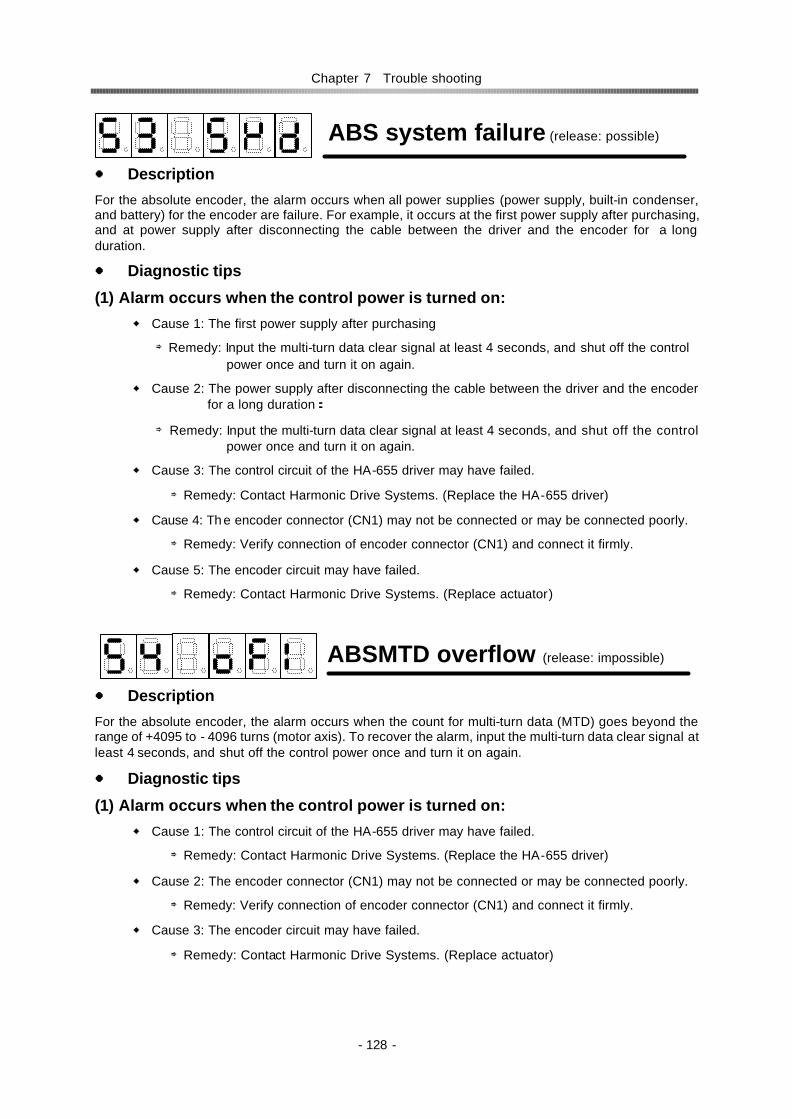
Chapter 7 Trouble shooting
- 128 -
ABS system failure (release: possible)
Description
For the absolute encoder, the alarm occurs when all power supplies (power supply, built-in condenser, and battery) for the encoder are failure. For example, it occurs at the first power supply after purchasing, and at power supply after disconnecting the cable between the driver and the encoder for a long duration.
Diagnostic tips
(1) Alarm occurs when the control power is turned on:
Cause 1: The first power supply after purchasing
⇒Remedy: Input the multi-turn data clear signal at least 4 seconds, and shut off the control power once and turn it on again.
Cause 2: The power supply after disconnecting the cable between the driver and the encoder for a long duration:
⇒Remedy: Input the multi-turn data clear signal at least 4 seconds, and shut off the control power once and turn it on again.
Cause 3: The control circuit of the HA-655 driver may have failed.
⇒Remedy: Contact Harmonic Drive Systems. (Replace the HA-655 driver)
Cause 4: Th e encoder connector (CN1) may not be connected or may be connected poorly.
⇒Remedy: Verify connection of encoder connector (CN1) and connect it firmly.
Cause 5: The encoder circuit may have failed.
⇒Remedy: Contact Harmonic Drive Systems. (Replace actuator)
ABSMTD overflow (release: impossible)
Description
For the absolute encoder, the alarm occurs when the count for multi-turn data (MTD) goes beyond the range of +4095 to - 4096 turns (motor axis). To recover the alarm, input the multi-turn data clear signal at least 4 seconds, and shut off the control power once and turn it on again.
Diagnostic tips
(1) Alarm occurs when the control power is turned on:
Cause 1: The control circuit of the HA-655 driver may have failed.
⇒Remedy: Contact Harmonic Drive Systems. (Replace the HA-655 driver)
Cause 2: The encoder connector (CN1) may not be connected or may be connected poorly.
⇒Remedy: Verify connection of encoder connector (CN1) and connect it firmly.
Cause 3: The encoder circuit may have failed.
⇒Remedy: Contact Harmonic Drive Systems. (Replace actuator)

Chapter 7 Trouble shooting
- 129 -
(2) Alarm occurs during running:
Cause 1: The alarm when the count for multi-turn data (MTD) goes beyond the range of +4095 to - 4096 turns (motor axis).
⇒Remedy: input the multi-turn data clear signal at least 4 seconds, and shut off the control power once and turn it on again.
ABS multi-turn data error (release: imp.)
Description
For the absolute encoder, during an energy-saving mode, where no power by power supply but the encoder circuit is active only by the power of a built-in condenser and a built-in battery, the alarm occurs when the encoder rotates too fast at the acceleration rate and speed exceeding the recording ability of the multi-turn counter on the mode. To recover the alarm, input the multi-turn data clear signal at least 4 seconds, and shut off the control power once and turn it on again.
Diagnostic tips
(1) Alarm occurs when the control power is turned on:
Cause 1: The encoder rotates during no control power supply.
⇒Remedy: Input the multi-turn data clear signal at least 4 seconds, and shut off the control power once and turn it on again.
Cause 2: The control circuit of the HA-655 driver may have failed.
⇒Remedy: Contact Harmonic Drive Systems. (Replace the HA-655 driver)
Cause 3: The encoder connector (CN1) may not be connected or may be connected poorly.
⇒Remedy: Verify connection of encoder connector (CN1) and connect it firmly.
Cause 4: The encoder circuit may have failed.
⇒Remedy: Contact Harmonic Drive Systems. (Replace actuator)
ABS low battery voltage (release: imp.)
Description
For the absolute encoder, when voltage of the built-in battery is low. To recover the alarm, change the battery for a new one, and shut off the control power once and turn it on again.
Diagnostic tips
(2) Alarm occurs when the control power is turned on:
Cause 1: The voltage of the built-in battery isles than 2.80V.
⇒Remedy: Change the battery for a new one.
Cause 2: The control circuit of the HA-655 driver may have failed.
⇒Remedy: Contact Harmonic Drive Systems. (Replace the HA-655 driver)
Cause 3: The encoder connector (CN1) may not be connected or may be connected poorly.
⇒Remedy: Verify connection of encoder connector (CN1) and connect it firmly.

Chapter 7 Trouble shooting
- 130 -
Cause 4: The encoder circuit may have failed.
⇒Remedy: Contact Harmonic Drive Systems. (Replace actuator)
(2) Alarm occurs during running:
Cause 1: The voltage of the built-in battery isles than 2.80V.
⇒Remedy: Change the battery for a new one.
ABS send data rule error (release: imp.)
Description
The absolute encoder rotates more than 127 resolvable pulses by external torque during transmitting absolute data. To recover the alarm, shut off the control power once and turn it on again.
Diagnostic tips
(2) Alarm occurs when the control power is turned on:
Cause 1: The absolute encoder rotates more than 127 resolvable pulses by external torque during transmitting absolute data.
⇒Remedy: Shut off the control power once and turn it on again.
Cause 2: The control circuit of the HA-655 driver may have failed.
⇒Remedy: Contact Harmonic Drive Systems. (Replace the HA-655 driver)
Cause 3: The encoder connector (CN1) may not be connected or may be connected poorly.
⇒Remedy: Verify connection of encoder connector (CN1) and connect it firmly.
Cause 4: The encoder circuit may have failed.
⇒Remedy: Contact Harmonic Drive Systems. (Replace actuator)
Error counter overflow (release: possible)
Description
The alarm occurs when an error count exceeds the set value in [parameter mode]→[6: position error allowance]. It is possible to release the alarm by inputting ON signal to [CN2-2 clear: CLEAR]. The error count is reset simultaneously.
Diagnostic tips
(1) Alarm occurs when the control power is turned on:
Cause 1: The control circuit of the HA-655 driver may have failed.
⇒Remedy: Contact Harmonic Drive Systems. (Replace the HA-655 driver)
(2) Alarm occurs during acceleration or deceleration
Cause 1: Gain is too low
⇒Remedy: Adjust gains [parameter mode]→[0: speed loop gain], [1: speed loop integral compensation] and [2: position loop gain].

Chapter 7 Trouble shooting
- 131 -
Cause 2: Parameters of the [electronic gear] are wrong.
⇒Remedy: Set the correct parameters by [parameter mode]→[3: electronic gear-denominator][4: electronic gear-numerator].
Cause 3: The [command pulse frequency] is too high
⇒Remedy: Lower the [command pulse frequency] of the host.
The frequency should be less than: Actuator’s rated speed (r/min)×60
You can monitor the frequency by [monitor mode]→[A: command pulse frequency]
Cause 4: The load inertia is too large
⇒Remedy1: Reduce the load inertia.
⇒Remedy2: Modify the motion profile to accelerate and decelerate more slowly.
(3) Speed did not rise with the command, and then the alarm occurs.
Cause 1: OFF state of input signal [CN2-4: FWD inhibit] or [CN2-5: REV inhibit].
⇒Remedy: Verify breakage of CN2 connector cable. Make sure both signals above are turning ON by [test mode]→[b: I/O monitor].
(4) Actuator did not rotate.
Cause 1: Incorrect motor cable connection or wrong phase order
⇒Remedy1: Correct the connection between the motor cable and the connector.
⇒Remedy2: Connect the motor cable and the connector in correct phase order referring to [Chapter 4-7: Connection Servomotor Cable and Regeneration Resistor] of this manual.
Cause 2: Poor encoder connector (CN1) connection.
⇒Remedy: Plug the CN1 connector firmly.
Memory failure (RAM) (release: impossible)
Description
This alarm occurs when the driver’s RAM memory fails. It is impossible to release the alarm.
Diagnostic tips occurs
(1) Alarm occurs when control power is turned on:
Cause 1: The control circuit of the HA-655 driver may have failed.
⇒Remedy: Contact Harmonic Drive Systems. (Replace the HA-655 driver)
(2) Alarm occurs while running
Cause 1: Malfunction of a control element of the HA-655 driver
⇒Remedy: Contact Harmonic Drive Systems. (Replace the HA-655 driver)
Make sure that the installed location is suitable, referring [4-3 location and installation] of this manual.

Chapter 7 Trouble shooting
- 132 -
Memory failure (EEROM) (release: imp.)
Description
This alarm occurs when the driver’s EEROM memory fails. It is impossible to release the alarm.
Diagnostic tips occurs
(1) Alarm occurs when the control power is turned on:
Cause 1: The control circuit of the HA-655 driver may have failed.
⇒Remedy: Contact Harmonic Drive Systems. (Replace the HA-655 driver)
(2) Alarm occurs during running
Cause 1: Malfunction of a control element of the HA-655 driver
⇒Remedy: Contact Harmonic Drive Systems. (Replace the HA-655 driver)
Make sure that the installed location is suitable, referring [4-3 location and installation] of this manual.
CPU failure (release: Impossible)
Description This alarm occurs when the driver’s CPU fails. It is impossible to release the alarm.
Diagnostic tips
(1) Alarm occurs when the control power is turned on:
Cause 1: The control circuit of the HA-655 driver may have failed.
⇒Remedy: Contact Harmonic Drive Systems. (Replace the HA-655 driver)
(2) Alarm occurs during running
Cause 1: Malfunction may be caused by surrounding electrical noise.
⇒Remedy: Install the driver correctly referring to [Chapter 4-4 noise suppression].
Cause 2: The control circuit of the HA-655 driver may have failed.
⇒Remedy: Contact Harmonic Drive Systems. (Replace the HA-655 driver)

Chapter 7 Trouble shooting
- 133 -
7-2 Troubleshooting for improper actuator motions Troubleshooting procedures for problems other than alarms are described separately in the position mode and in the speed mode. They are also described for the following cases:
No rotation
Unstable rotation
Poor positioning accuracy
Note: In the flowcharts, [Y] means [yes], and [N] means [no].
7-2-1 Improper motions in position mode
No rotation
Start
LED of front panel
indicating?
Main power OK?
Are NFB, MS ON?
・Power failure ・NFB or MS failure ・Wrong wiring
N N Y
MS open with power ON
sequence?
N
Driver failure
Y
Recover power after removing the cause.
Y
N
Turn NFB and MS ON.
Alarm indicated?
Refer section 7-1: alarm and
diagnostic tips.
Y
N
Y
Note: NFB: No-fuse breaker MS: Main power switch
Can actuator be rotated by
hand?
N Is [b: torque limit]
correct?
Correct [b: torque limit].
Y
Driver failure
N
Command coming in?
Input command. N
N
Loose screws in
connection, broken wire?
Tighten screws. Replace motor
cable.
Y
Y
N Is voltage of driver’s UVW
correct?
Y
N Is phase order
correct? Correct them.
Y
Y
Actuator failure
Is command configuration
correct?
Make same command configuration as of
host.
N
Y
To next page.

Chapter 7 Trouble shooting
- 134 -
Unstable rotation
N
Loosen screws in
connection, broken wire?
Verify motor cable connection.
N Is phase order
correct? Correct them.
Y
N
No layer short,
grounding in motor?
Y
Y Actuator failure
Is output shaft
locking?
Y Release locking.
N
Actuator failure
Is CN2-2 CLEAR
ON?
Turn OFF CN2-2 CLEAR.
N
Y
From prior page
Supply voltage correct?
Input correct
voltage.
N
Is voltage within its
allowance?
Review capacity of transformer and
other power device
Y
N
Y
Start
To next page.

Chapter 7 Trouble shooting
- 135 -
Is normal temperature in cabinet?
Review heat generating devices, and cooling system.
N
From prior page
Y
Command pulse train correct?
Correct signal voltage, frequency and synchronization. Check for electrical noise in signal cables.
N
Y
Is speed lower than rated one?
Lower the actuator speed than rated one.
N
Y
Adjust gains correctly.
Large fluctuation in load torque?
Lower its fluctuation. Use higher output
actuator.
N
Y
Gain adjustment possible?
N
Y
Adjust gains correctly.
N Motor
wiring from driver
correct?
Verify motor cable connections.
Y
N Is torque limit value too small?
Set [b: torque limit] normal.
Y
N Is CN2-2 CLEAR ON sometimes?
Try to open (OFF) CN2-2 CLEAR
Y
To next page
Is load inertia
proper?
Lower load inertia
N
Y
Gain adjustment possible?
N

Chapter 7 Trouble shooting
- 136 -
Poor positioning accuracy
N Is encoder
signal normal?
Improve grounding and cable installation.
Use shield cable.
Y
From prior page
N
Is noise on encoder signal?
Y
Actuator failure
N Is there play or resonance in mechanism?
Y
Improve mechanism.
Actuator or driver failure
In host program correct?
Correct it.
N
Command pulse
normal?
Correct pulse frequency.
Check noise.
Y
N
Y
Start
To next page
Command pulse timing
normal?
Check command pulse in the host.
Y
N
Electronic gear
correct?
Correct electronic gear parameters.
N

Chapter 7 Trouble shooting
- 137 -
7-2-2 Improper motions in speed mode
No rotation
Is load inertia
proper?
Lower load inertia
N
Y
From prior page
Gain adjustment possible?
N
Y
Adjust gains correctly.
N Is play or resonance in mechanism?
Y
Improve mechanism.
Actuator or driver failure
Start
LED of front panel
indicating?
Main power OK?
Are NFB, MS ON?
・Power failure ・NFB or MS failure ・Wrong wiring
N N Y
MS open with power ON
sequence?
N
Driver failure
Y
Recover power after removing the cause.
Y
N
Turn NFB and MS ON.
Alarm indicated?
Refer section 7-1: alarm and
diagnostic tips.
Y
N
Y
Note: NFB: No-fuse breaker MS: Main power switch
Can actuator rotate by
hand?
N Is [b: torque
limit] correct?
Correct [b: torque limit].
Y
N
Speed command coming?
Input it.
N
N
Loosen screws in
connection, broken wire?
Tighten screws. Replace motor
cable.
Y
Y
Y
To A of next page To B of next page

Chapter 7 Trouble shooting
- 138 -
Unstable rotation
Driver failure
N Is voltage of driver’s U V Wcorrect?
N Is phase
order correct?
Correct them.
Y
Y
Actuator failure
Form A of prior page From B of prior page
N
Loose screws in
connection, broken wire?
Verify motor cable connection.
N Is phase
order correct?
Correct them.
Y
N
No layer short,
grounding in motor?
Y
Y Actuator failure
Is output shaft
locking?
Y Release locking.
N
Actuator failure
Supply voltage correct?
To next page
Input correct voltage.
N
Is voltage within its
allowance?
Review transformer and other power
capacities
Y
N
Y
Start
Is temperature normal in cabinet?
Review heat generating devices and the cooling system.
N
Y

Chapter 7 Trouble shooting
- 139 -
From prior page
Command voltage form
correct?
If there is a ripple on signal, stabilize it. Check for electrical noise.
N
Y
Speed lower than rated
speed?
Adjust actuator speed lower than rated speed.
N
Y
Adjust gains correctly.
Large fluctuation in load torque?
Lower its fluctuation. Use higher output
actuator.
N
Y
Gain adjustment possible?
N
Y
Adjust gains correctly.
N Is the Motor wiring from
driver correct?
Verify motor cable connections.
Y
N Is torque
limit value too small?
Set [b: torque limit] normal.
Y
To next page
Is load inertia
proper?
Lower load inertia
N
Y
Gain adjustment possible?
N
N Is encoder signal
normal?
Improve grounding and cable installation.
Use shield cable.
Y N
Is there noise in the
encoder signal?
Y
Actuator failure

Chapter 7 Trouble shooting
- 140 -
From prior page
N Is there play or resonance in mechanism?
Y
Improve mechanism.
Actuator or driver failure
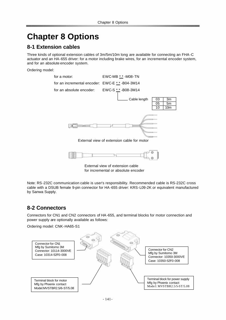
Chapter 8 Options
- 141-
Chapter 8 Options 8-1 Extension cables Three kinds of optional extension cables of 3m/5m/10m long are available for connecting an FHA-C actuator and an HA-655 driver: for a motor including brake wires, for an incremental encoder system, and for an absolute encoder system.
Ordering model:
for a motor: EWC-MB * * -M08-TN
for an incremental encoder: EWC-E * * -B04-3M14
for an absolute encoder: EWC-S * * -B08-3M14
Note: RS -232C communication cable is user’s responsibility. Recommended cable is RS-232C cross cable with a DSUB female 9-pin connector for HA -655 driver: KRS-L09-2K or equivalent manufactured by Sanwa Supply.
8-2 Connectors Connectors for CN1 and CN2 connectors of HA-655, and terminal blocks for motor connection and power supply are optionally available as follows:
Ordering model: CNK-HA65-S1
Connector for CN2 Mfg by Sumitomo 3M Connector: 10350-3000VE Case: 10350-52F0-008
Terminal block for power supply Mfg by Phoenix contact Model: MVSTBR2.5/5-ST/5.08
Connector for CN1 Mfg by Sumitomo 3M Connector: 10114-3000VE Case: 10314-52F0-008
Terminal block for motor Mfg by Phoenix contact Model:MVSTBR2.5/6-ST/5.08
Cable length 03 3m 05 5m 10 10m
External view of extension cable for motor
External view of extension cable for motor
External view of extension cable for incremental or absolute encoder

Chapter 8 Options
- 142-
8-3 Software for setting up parameters The software helps out with setting up parameters of HA-655 driver connecting a personal computer.
For the details of the software, please ask us the instructions of PSF-650 software.
Ordering model: PSF-650
Operating system: Windows95/98/Me/NT Notice: Windows is a registered trademark of Microsoft Corporation.
Link to CN3 port of HA-655 driver: RS-232C cable
8-4 Backup battery for absolute encoders
For protecting the absolute memory against volatilizing while control power is OFF, the HA-655 driver provides a battery.
Ordering model: HAB-ER17/33
Lifetime: about one year after control power OFF (conditions: at ambient temperature: 25 degree C, no rotation) actual lifetime depends on servicing conditions.
Specifications: lithium battery model: ER17/33 (3.6V 1600mAh) manufactured by Hitachi Maxell co., Ltd. Harmonic Drive Systems Inc. is possible to supply the batteries on request.
HA-
RS-232C cable
CN3
PSF-650 set-up software
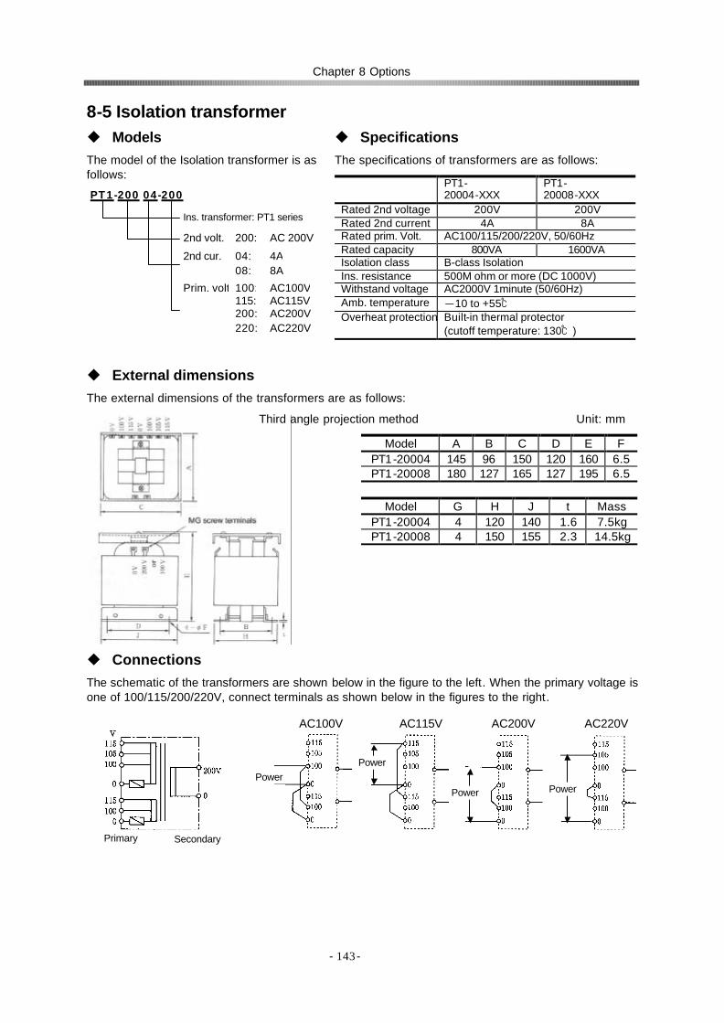
Chapter 8 Options
- 143-
8-5 Isolation transformer u Models The model of the Isolation transformer is as follows:
u Specifications The specifications of transformers are as follows:
PT1- 20004-XXX
PT1- 20008-XXX
Rated 2nd voltage 200V 200V Rated 2nd current 4A 8A Rated prim. Volt. AC100/115/200/220V, 50/60Hz Rated capacity 800VA 1600VA Isolation class B-class Isolation Ins. resistance 500M ohm or more (DC 1000V) Withstand voltage AC2000V 1minute (50/60Hz) Amb. temperature -10 to +55 Overheat protection Built-in thermal protector
(cutoff temperature: 130)
u External dimensions The external dimensions of the transformers are as follows:
Third angle projection method Unit: mm
Model A B C D E F PT1-20004 145 96 150 120 160 6.5 PT1-20008 180 127 165 127 195 6.5
Model G H J t Mass
PT1-20004 4 120 140 1.6 7.5kg PT1-20008 4 150 155 2.3 14.5kg
u Connections The schematic of the transformers are shown below in the figure to the left. When the primary voltage is one of 100/115/200/220V, connect terminals as shown below in the figures to the right.
PT1-200 04-200
Ins. transformer: PT1 series
2nd volt. 200: AC 200V
2nd cur. 04: 4A 08: 8A
Prim. volt 100: AC100V 115: AC115V 200: AC200V 220: AC220V
Primary Secondary
AC100V AC115V AC200V AC220V
Power Power
Power Power

HA655 series servo driver manual
- Index 1 -
Index
+24V ・・・・・・・・・・・・・・・・・・・・・・・・・・・・・・・36 1-pulse train ・・・・・・・・・・・・・・・・・・・・・ 14,105 2-phase-pulse train ・・・・・・・・・・・・・・・ 15,105 2-pulse-train ・・・・・・・・・・・・・・・・・・・・・ 14,105 A-B phase with 90°difference・・・・・・・・・・15 Abnormal encoder signal ・・・・・・・・・・・・・127 Abnormal regeneration ・・・・・・・・・・・・・・・126 ABS-CLEAR ・・・・・・・・・・・・・・・・・・・・・35, 50 ABS low battery voltage ・・・・・・・・・・・・・・129 ABSMTD overflow・・・・・・・・・・・・・・・・・・・128 ABS multi-turn data clear ・・・ 18, 35, 50, 111 ABS multi-turn data error ・・・・・・・・・・・・・129 Absolute data request ・・・・・・・・・・ 21, 35, 50 Absolute encoder ・・・・・・・ 17, 32, 43, 46, 56 ABS-REQ・・・・・・・・・・・・・・・・・・・・・・・・35, 50 ABS send data rule error ・・・・・・・・・・・・・130 ABS system failure ・・・・・・・・・・・・・・・・・・128 Acceleration time constant ・・・・・・・・・ 29,100 Actuator code・・・・・・・・・・・・・・・・・・・・・・・・91 ALARM ・・・・・・・・・・・・・・・・・・・・・・・・・・38, 52 Alarm ・・・・・・・・・・・・・・・・・・・・・・・・・・・ 39,53 Alarm history ・・・・・・・・・・・・・・・・・・・・・・・・90 Alarm logic ・・・・・・・・・・・・・・・・・・・・・・・・・ 111 ALM-A, -B, -C, -D ・・・・・・・・・・・・・・・・・39, 53 Analog monitor manual output ・・・・・・・・・ 119 Acquisition sequence ・・・・・・・・・・・・・・・・・18 Attained speed・・・・・・・・・・・・・・・・・・・・52, 98 Backup system ・・・・・・・・・・・・・・・・・・・・・・22 Battery ・・・・・・・・・・・・・・・・・・・・・・・・ 22, 142 Cable ・・・・・・・・・・・・・・・・・・・・・・・・・ 64, 141 Circuit breaker ・・・・・・・・・・・・・・・・・・・・・・・65 CLEAR ・・・・・・・・・・・・・・・・・・・・・・・・・・34, 48 Clear・・・・・・・・・・・・・・・・・・・・・・・・・・・・34, 48 CMD-CHG ・・・・・・・・・・・・・・・・・・・・・・・29, 40 Command change ・・・・・・・・・・・・・・ 29,40,49 Command configuration ・・・・・・・・・・ 14, 105 Command pulse frequency・・・・・・・・・・・・・88 Command pulse ・・・・・・・・・・・・・・・・・・・・・87 Command transmitting ・・・・・・・・・・・・・・・・16 Condenser ・・・・・・・・・・・・・・・・・・・・・・・・・・22 Connector ・・・・・・・・・・・・・・・・・・・ 32,46,141 Control mode ・・・・・・・・・・・・・・・・・・・・・・・104 Counter・・・・・・・・・・・・・・・・・・・・・・・・・・・・・17 CPU failure・・・・・・・・・・・・・・・・・・・・・・・・・132 CUR-MON ・・・・・・・・・・・・・・・・・・・・・・・ 35,50 Current monitor ・・・・・・・・・・・・・・・・35,50,119 Daily maintenance・・・・・・・・・・・・・・・・・・・・78 Data request ・・・・・・・・・・・・・・・・・・・・・・・・21
Deceleration time constant ・・・・・・・・ 19, 100 Default ・・・・・・・・・・・・・・・・・・・・・・・・・・・・121 EIA-422A ・・・・・・・・・・・・・・・・・・・・・・・・・・・16 Electronic gear・・・・・・・・・・・・・・・・・・ 15, 106 Encoder cable ・・・・・・・・・・・・・・・・・・・ 66,141 Encoder failure ・・・・・・・・・・・・・・・・・・・・・126 Encoder signal ・・・・・・・・・・・・・・・・・・・・・・・16 Energy saving mode ・・・・・・・・・・・・・・・・・・17 Environmental condition ・・・・・・・・・・・・・・・59 Error counter cleared by S-ON・・・・・・・・・107 Error counter state・・・・・・・・・・・・・・・・・・・・82 Error counter overflow・・・・・・・・・・・・・・・・130 Error counts ・・・・・・・・・・・・・・・・・・・・・・・・・24 Error pulse counts ・・・・・・・・・・・・・・・・・・・・84 Exchanging procedure ・・・・・・・・・・・・・・・・22 Feedback pulse ・・・・・・・・・・・・・・・・・・・・・・86 Feed-forward ・・・・・・・・・・・・・・・・・・・・・・・・25 Feed-forward gain ・・・・・・・・・・・・・・・・・・・・97 FG・・・・・・・・・・・・・・・・・・・・・・・・・・・・・・40, 54 FWD-EN・・・・・・・・・・・・・・・・・・・・・・・・・・・・49 FWD enable ・・・・・・・・・・・・・・・・・・・・・・27, 49 FWD inhibit ・・・・・・・・・・・・・・・・・・・・・・26, 34 FWD pulse ・・・・・・・・・・・・・・・・・・・・・・・・・・36 FWD/REV pulse train ・・・・・・・・・・・・・・・・・14 Fuse ・・・・・・・・・・・・・・・・・・・・・・・・・・・・・・・65 Gain ・・・・・・・・・・・・・・・・・・・・・・・・・・・・・・・24 Grounding ・・・・・・・・・・・・・・・・・・・・・・・・・・60 Grounding cable ・・・・・・・・・・・・・・・・・・・・・63 Ground wire ・・・・・・・・・・・・・・・・・・・・・・・・・65 HI-SPD ・・・・・・・・・・・・・・・・・・・・・・・・・・・・・52 Humidity ・・・・・・・・・・・・・・・・・・・・・・・・・・・・59 Hunting ・・・・・・・・・・・・・・・・・・・・・・・・・・94, 96 I/O monitor ・・・・・・・・・・・・・・・・・・ 30, 89, 118 I/O port connection ・・・・・・・・・・・・・・・・33, 47 I/O ports ・・・・・・・・・・・・・・・・・・ 31, 32, 45, 46 I/O signal cable ・・・・・・・・・・・・・・・・・・・・・・66 Impact・・・・・・・・・・・・・・・・・・・・・・・・・・・・・・59 Incremental encoder ・・・・・ 16, 31, 41, 45, 55 Index・・・・・・・・・・・・・・・・・・・・・・・・・・・・・・・16 IN-POS ・・・・・・・・・・・・・・・・・・・・・・・・・・・・・37 In-position ・・・・・・・・・・・・・・・・・・・・・・・26, 37 In-position range ・・・・・・・・・・・・・・・・・・・・・98 Input ・・・・・・・・・・・・・・・・・・・・・・・・・・・・33, 47 INPUT-COM・・・・・・・・・・・・・・・ 34, 35, 48, 49 Input common ・・・・・・・・・・・・・ 34, 35, 48, 49 Input port ・・・・・・・・・・・・・・・・・・・・・・・・・・・36 Input signal common ・・・・・・・・・・・・・・・34, 48 Installing ・・・・・・・・・・・・・・・・・・・・・・・・・・・・60

HA655 series servo driver manual
- Index 2 -
Internal speed command ・・・・・・・・・・・・・・99 Isolation transformer ・・・・・・・・・・・・・ 64, 143 JOG acceleration・・・・・・・・・・・・・・・・・・・・ 116 JOG operation ・・・・・・・・・・・・・・・・・・30, 115 JOG speed ・・・・・・・・・・・・・・・・・・・・・・・・・ 116 Kp ・・・・・・・・・・・・・・・・・・・・・・・・・・・・・・・・・24 Line-driver ・・・・・・・・・・・・・・・・・・・・・・・16, 36 Manual JOG operation ・・・・・・・・・・・・・・・・30 Memory failure (EEROM) ・・・・・・・・・・・・・132 Memory failure (RAM) ・・・・・・・・・・・・・・・・131 Monitor mode・・・・・・・・・・・・・・・・・・・・・・・・81 Motor speed ・・・・・・・・・・・・・・・・・・ 27, 51, 83 Multiplication ・・・・・・・・・・・・・・・・・・・・・・・・15 Multiplication of 2-phase pulse・・・・・・・・・105 Multi-turn counter ・・・・・・・・・・・・・・・・・・・・17 Multi-turn data clear ・・・・・・・・・・・・・・・・・・21 Noise suppression・・・・・・・・・・・・・・・・・・・・60 Noise filter ・・・・・・・・・・・・・・・・・・・・・・・・・・61 Open collector ・・・・・・・・・・・・・・・・・・・・16, 37 OUT-COM ・・・・・・・・・・・・・・・・・・・・・・・39, 53 Output port operation ・・・・・・・・・・・・・・・・ 117 Output・・・・・・・・・・・・・・・・・・・・・・・・・・・33, 47 Output common・・・・・・・・・・・・・・・・・・・39, 53 Over current ・・・・・・・・・・・・・・・・・・・・・・・・125 Overheat ・・・・・・・・・・・・・・・・・・・・・・・・・・125 Over speed ・・・・・・・・・・・・・・・・・・・・・・・・123 Overload・・・・・・・・・・・・・・・・・・・・・・・・・・・124 Overload rate・・・・・・・・・・・・・・・・・・・・・・・・85 Overshoot ・・・・・・・・・・・・・・・・・・・・・・・94, 96 Parameter mode ・・・・・・・・・・・・・・・・・・・・102 Phase-A output ・・・・・・・・・・・・・・・・・・・40, 54 Phase-A pulse ・・・・・・・・・・・・・・・・・・・・・・・16 Phase-B output ・・・・・・・・・・・・・・・・・・・40, 54 Phase-B pulse ・・・・・・・・・・・・・・・・・・・・・・・16 Phase-C ・・・・・・・・・・・・・・・・・・・・・・・・・・・・16 Phase-C pulse ・・・・・・・・・・・・・・・・・・・・・・・16 Phase-Z ・・・・・・・・・・・・・・・・・・・・・ 16, 39, 53 Pin-layout ・・・・・・・・・・・・・・・・・・・・・・・・66, 67 Polarity + pulse train ・・・・・・・・・・・・・・・・・・14 Position error allowance ・・・・・・・・・・・・・・108 Position mode ・・・・・・・・・・・・・・・・・・・・・・・14 Position loop ・・・・・・・・・・・・・・・・・・・・・・・・24 Position loop gain ・・・・・・・・・・・・・・・・・24, 96 Power cable ・・・・・・・・・・・・・・・・・・・・・・・・・63 Power consumption・・・・・・・・・・・・・・・・・・・59 Power supply ・・・・・・・・・・・・・・・・・・・・・・・・63 Power-OFF sequence・・・・・・・・・・・・・・・・・68 Power-ON sequence・・・・・・・・・・・・・・・・・・68
Protocol ・・・・・・・・・・・・・・・・・・・・・・・・・・・・20 Pulse count indication・・・・・・・・・・・・・・・・・30 Quadruple ・・・・・・・・・・・・・・・・・・・・・ 15, 105 Ready ・・・・・・・・・・・・・・・・・・・・・・・・・・・38, 52 Regenerative resistor cable ・・・・・・・・・・・・65 Reset ・・・・・・・・・・・・・・・・・・・・・・・・・・・・・・22 REV-EN ・・・・・・・・・・・・・・・・・・・・・・・・・・・・49 REV enable ・・・・・・・・・・・・・・・・・・・・・・27, 49 REV inhibit ・・・・・・・・・・・・・・・・・・・・・・・26, 34 REV pulse ・・・・・・・・・・・・・・・・・・・・・・・・・・36 Rotary direction ・・・・・・・・・・・・・・・・・・・・・109 RS-232C ・・・・・・・・・・・・・・・・・・・・ 5, 20, 141 Serial port connector ・・・・・・・・・・・・・・・・・・・5 Service humidity ・・・・・・・・・・・・・・・・・・・・・59 Service temperature ・・・・・・・・・・・・・・・・・・59 Servo gain ・・・・・・・・・・・・・・・・・・・・・・・・・・28 Servo-ON ・・・・・・・・・・・・・・・・・・・・・・・・34, 48 SG-GND ・・・・・・・・・・・・・・・・・・・・・・・・・・・・51 Single-turn absolute encoder ・・・・・・・・・・・17 Single-turn count ・・・・・・・・・・・・・・・・・・・・・19 Software ・・・・・・・・・・・・・・・・・・・・・・・・・・・142 S-ON・・・・・・・・・・・・・・・・・・・・・・・・・・・・34, 48 SPD-CMD ・・・・・・・・・・・・・・・・・・・・・・・・・・51 SPD-MON ・・・・・・・・・・・・・・・・・・・・・・・35, 50 Speed command common ・・・・・・・・・・・・・51 Speed command ・・・・・・・・・・・・・・・・・・27, 51 Speed command voltage ・・・・・・・・・・・27, 83 Speed command offset ・・・・・・・・・・・ 27, 101 Speed command auto-offset ・・・・・・・・・・120 Speed mode・・・・・・・・・・・・・・・・・・・・・・27, 45 Speed conversion factor ・・・・・・・・・・ 27, 109 Speed limit ・・・・・・・・・・・・・・・・・・・・・・・・・ 110 Speed loop・・・・・・・・・・・・・・・・・・・・・・・・・・24 Speed loop gain・・・・・・・・・・・・・・・ 25, 28, 94 Speed loop integral compensation 25, 28, 95 Speed monitor ・・・・・・・・・・・・・・・ 27, 50, 119 Temperature・・・・・・・・・・・・・・・・・・・・・・・・・59 Test mode ・・・・・・・・・・・・・・・・・・・・・・・・・ 113 Test run・・・・・・・・・・・・・・・・・・・・・・・・・・・・・70 Torque limit・・・・・・・・・・・・・・・・・・・・・・・・・ 110 Torque monitor・・・・・・・・・・・・・・・・・・・・・・・85 Tune mode ・・・・・・・・・・・・・・・・・・・・・・・・・・92 Usual operation ・・・・・・・・・・・・・・・・・・・・・・78 UVW failure ・・・・・・・・・・・・・・・・・・・・・・・・127 Vibration ・・・・・・・・・・・・・・・・・・・・・・・・・・・59 Wire size ・・・・・・・・・・・・・・・・・・・・・・・・・・・63 Z ・・・・・・・・・・・・・・・・・・・・・・・・・・・・・・・39, 53 Zero clamp・・・・・・・・・・・・・・・・・・・・・ 29, 108

The HA-655 series drivers are warranted as follows:
Warranty period
Under the condition that the actuator are handled, used and maintained properly followed each item of the documents and the manuals, all the HA-655 series drivers are warranted against defects in workmanship and materials for the shorter period of either one year after delivery or 2,000 hours of operation time.
Warranty terms
All the HA-655 series drivers are warranted against defects in workmanship and materials for the warranted period. This limited warranty does not apply to any product that has been subject to:
(1) user's misapplication, improper installation, inadequate maintenance, or misuse.
(2) disassembling, modification or repair by others than Harmonic Drive LLC
(3) imperfection caused by the other than the FHA-C series actuator and the HA-655 servo driver.
(4) disaster or others that does not belong to the responsibility of Harmonic DriveSystems, Inc.
Our liability shall be limited exclusively to repairing or replacing the product only found by Harmonic Drive LLC to be defective. Harmonic Drive LLC shall not be liable for consequential damages of other equipment caused by the defective products, and shall not be liable for the incidental and consequential expenses and the labor costs for detaching and installing to the driven equipment
Warranty Period and Terms

Worldwide Locations:
Harmonic Drive Systems, Inc.Minamiohi 6-25-3, Shinagawa-kuTokyo 140, Japan
Harmonic Drive AGHoenbergstr, 14Limburg/Lahn, D-65555 Germany
HA-655 manual rev_04-06
Harmonic Drive LLCBoston247 Lynnfield StreetPeabody, MA 01960
New York89 Cabot CourtHauppauge, NY 11788
800-921-3332
F: 978-532-9406
www.HarmonicDrive.net


![Driver & Vehicle Policy - Automotional Generic Driver Vehicle... · [ ] uk ltd 08 contents . policy statement 3 the company’s and driver’s responsibilities (under the management](https://img.dokumen.tips/doc/110x75/5a73ff967f8b9aa3688b82cd/driver-vehicle-policy-automotional-generic-driver-vehicle-uk-ltd.jpg)


![Driver & Vehicle Policy - Fleet Driver Training - Automotionalautomotional.com/library/060816 Generic Driver Vehicle Policy doc.pdf · Driver & Vehicle Policy 1 [ ] UK Ltd 08 Contents](https://img.dokumen.tips/doc/110x75/5a9df2d87f8b9a4a238c9335/driver-vehicle-policy-fleet-driver-training-auto-generic-driver-vehicle-policy.jpg)


