Embed Size (px)
Citation preview

TM-H6000/H6000PDeveloper's Guide
Using this online developer’s guide
The words on the left side of this screen are bookmarks for all the topics in this guide.
Use the scroll bar next to the bookmarks to find any topic you want. Click a bookmark to instantly jump to its topic. (If you wish, you can increase the size of the bookmark area by dragging the dividing bar to the right.)
Use the scroll bar on the right side of this screen to move throughthe text.
Use the zoom tools to magnify or reduce the page display.
Click the Find button if you want to search for a particular term. (However, using the bookmarks is usually quicker.)
Complete online documentation for Acrobat Reader is located in the Help directory for Acrobat Reader.
Confidential
Confidential
developer’s guideTM-H6000/H6000P
Copied Date 199 , ,
Copied by
EPSON English401053701

v
TM-H6000/H6000P Developer’s GuideConfidentialCONFIDENTIALITY AGREEMENT
BY USING THIS DOCUMENT, YOU AGREE TO ABIDE BY THE TERMS OF THIS AGREEMENT. PLEASE RETURN THIS DOCUMENT IMMEDIATELY IF YOU DO NOT AGREE TO THESE TERMS.
This document contains confidential, proprietary information of Seiko Epson Corporation or its affiliates. You must keep such information confidential. If the user is a business entity or organization, you must limit disclosure to your employees, agents, and contractors who have a need to know and who are also bound by obligations of confidentiality.
On the earlier of (a) termination of your relationship with Seiko Epson, or (b) Seiko Epson’s request, you must stop using the confidential information. You must then return or destroy the information, as directed by Seiko Epson.
If a court, arbitrator, government agency, or the like orders you to disclose any confidential information, you must immediately notify Seiko Epson. You agree to give Seiko Epson reasonable cooperation and assistance in resisting disclosure.
You may use confidential information only for the purpose of operating or servicing the products to which the document relates, unless you obtain the prior written consent of Seiko Epson for some other use.
Seiko Epson warrants that it has the right to disclose the confidential information. SEIKO EPSON MAKES NO OTHER WARRANTIES CONCERNING THE CONFIDENTIAL INFORMATION OR ANY OTHER INFORMATION IN THE DOCUMENT, INCLUDING (WITHOUT LIMITATION) ANY WARRANTY OF TITLE OR NON-INFRINGEMENT. Seiko Epson has no liability for loss or damage arising from or relating to your use of or reliance on the information in the document.
You may not reproduce, store, or transmit the confidential information in any form or by any means (electronic, mechanical, photocopying, recording, or otherwise) without the prior written permission of Seiko Epson.
Your obligations under this Agreement are in addition to any other legal obligations. Seiko Epson does not waive any right under this Agreement by failing to exercise it. The laws of Japan apply to this Agreement.
CAUTIONS This document shall apply only to the product(s) identified herein.
No part of this document may be reproduced, stored in a retrieval system, or transmitted in any form or by any means, electronic, mechanical, photocopying, recording, or otherwise, without the prior written permission of Seiko Epson Corporation.
The contents of this document are subject to change without notice. Please contact us for the latest information.
While every precaution has been taken in the preparation of this document, Seiko Epson Corporation assumes no responsibility for errors or omissions.
Neither is any liability assumed for damages resulting from the use of the information contained herein.
Neither Seiko Epson Corporation nor its affiliates shall be liable to the purchaser of this product or third parties for damages, losses, costs, or expenses incurred by the purchaser or third parties as a result of: accident, misuse, or abuse of this product or unauthorized modifications, repairs, or alterations to this product, or (excluding the U.S.) failure to strictly comply with Seiko Epson Corporation's operating and maintenance instructions.
Seiko Epson Corporation shall not be liable against any damages or problems arising from the use of any options or any consumable products other than those designated as Original EPSON Products or EPSON Approved Products by Seiko Epson Corporation.
TRADEMARKSEPSON® is a registered trademark of Seiko Epson Corporation.
General Notice: Other product and company names used herein are for identification purposes only and may be trademarks of their respective companies.
vi
ConfidentialRevision Information
Revision Page Altered Items and Contents
Rev. A
vii
TM-H6000/H6000P Developer’s GuideConfidentialAbout This Manual
Aim of the Manual
This manual was created to provide the information on the TM-H6000 printer for anyone who is developing hardware, installations, or programs. Programmers will also want to consult the “ESC/POS Application programming Guide.”
Contents of the Manual
The configuration of the manual is as follows:
Note:The contents regarding the firmware in this guide are described based on version 1.11 ESC/POS.
Chapter 1, “General Information” General description of features plus information on such matters as DIP switches, memory switches, error processing, sensors, self tests, and hex dumps.
Chapter 2, “Hardware” Contains specifications and interface information.
Chapter 3, ”ESC/POS Commands” Contains a list of commands supported by the TM-H6000 printer.
Chapter 4, ”Programming Guide and Tips”
Includes programming guide for FAQ and other programming information.
Chapter 5, “Installation, Printer Handling, including MICR and endorsement printing, Removing a Paper Jam”
Gives information on how to install and use the printer. Provides much more information than the User’s Manual.
Appendix A, “Character Code Tables” Provides all the character code tables available for the printer.
Appendix B, “Case Specifications” Outside dimensions of the printer.
Appendix C, “Maintenance Area” Shows the area required for access to the printer.
Appendix D, “Definitions” Definitions of useful terms.

viii
ConfidentialRelated Software and Documents
Related software and documents
Software/document name Description
Application Programming Guide This provides descriptions in Acrobat format of the commands used by each TM printer, along with sample programs and other information about the printers
TM-H6000/H6000P User’s Manual Provides basic handling procedures for the end user of the printer
TM-H6000 Service Manual Provides information for anyone who is maintaining and repairing the printer
ix
TM-H6000/H6000P Developer’s GuideConfidential
Safety Precautions
EMC and Safety Standards Applied
Product Name: TM-H6000/TM-H6000P
Type Name: M147A
The following standards are applied only to the printers that are so labeled. (EMC is tested using the EPSON PS-170 power supply.)
Europe: CE markingSafety: EN 60950
North America: EMI: FCC/ICES-003 Class ASafety: UL 1950/CSA C22.2 No. 950
Japan: EMC: VCCI Class AJEIDA-52
Oceania: EMC: AS/NZS 3548 Class B
WARNINGThe connection of a non-shielded printer interface cable to this printer will invalidate the EMC standards of this device.
You are cautioned that changes or modifications not expressly approved by Seiko Epson could void your authority to operate the equipment.
CE Marking
The printer conforms to the following Directives and Norms
Directive 89/336/EECEN 55022 Class BEN 50082-1
IEC 801-2 IEC 801-3 IEC 801-4
Directive 90/384/EECEN45501
FCC Compliance StatementFor American Users
This equipment has been tested and found to comply with the limits for a Class A digital device, pursuant to Part 15 of the FCC Rules. These limits are designed to provide reasonable protection against harmful interference when the equipment is operated in a commercial environment.
This equipment generates, uses, and can radiate radio frequency energy and, if not installed and used in accordance with the instruction manual, may cause harmful interference to radio communications. Operation of this equipment in a residential area is likely to cause harmful interference, in which case the user will be required to correct the interference at his own expense.
x
ConfidentialFor Canadian Users
This Class A digital apparatus complies with Canadian ICES-003.
Cet appareil numérique de la classe A est conforme à la norme NMB-003 du Canada.
GEREÄUSCHPEGEL
Gemäß der Dritten Verordnung zum Gerätesicherheitsgesetz (Maschinenlärminformations- Verordnung-3. GSGV) ist der arbeitsplatzbezogene Geräusch-Emissionswert kleiner als 70 dB(A) (basierend auf ISO 7779).
Key to Symbols
The following symbols are used in the documentation for this product. See the specific warnings and cautions at appropriate points throughout this guide.
WARNING:Warnings must be followed carefully to avoid serious bodily injury.
CAUTION:Cautions must be observed to avoid minor injury to yourself or damage to your equipment.
Note:Notes have important information and useful tips on the operation of your printer.
xi
TM-H6000/H6000P Developer’s GuideConfidentialSafety Precautions
This section presents important information to ensure safe and effective use of this product. Please read this section carefully and store it in an accessible location.
WARNING: Shut down your equipment immediately if it produces smoke, a strange odor, or
unusual noise. Continued use may lead to fire or electric shock. Immediately unplug the equipment and contact your dealer or a Seiko Epson service center for advice.
Never attempt to repair this product yourself. Improper repair work can be dangerous.
Never disassemble or modify this product. Tampering with this product may result in injury, fire, or electric shock.
Be sure to use the specified power source. Connection to an improper power source may cause fire or shock.
Never insert or disconnect the power plug with wet hands. Doing so may result in severe shock.
Do not allow foreign matter to fall into the equipment. Penetration of foreign objects may lead to fire or shock.
If water or other liquid spills into this equipment, unplug the power cord immediately, and then contact your dealer or a Seiko Epson service center for advice.Continued usage may lead to fire or shock.
Do not place multiple loads on the power outlet (wall outlet). Overloading the outlet may lead to fire.
Always supply power directly from a standard domestic power outlet.
Handle the power cord with care. Improper handling may lead to fire or shock.
• Do not modify or attempt to repair the cord.
• Do not place any object on top of the cord.
• Avoid excessive bending, twisting, and pulling.
• Do not place cord near heating equipment.
• Check that the plug is clean before plugging it in.
• Be sure to push the prongs all the way in.
If the cord becomes damaged, obtain a replacement from your dealer or a Seiko Epson service center.
xii
Confidential
CAUTION: Do not connect cables other than as described in this manual. Different
connections may cause equipment damage and burning.
Be sure to set this equipment on a firm, stable, horizontal surface.Product may break or cause injury if it falls.
Do not use in locations subject to high humidity or dust levels.Excessive humidity and dust may cause equipment damage, fire, or shock.
Do not place heavy objects on top of this product. Never stand or lean on this product. Equipment may fall or collapse, causing breakage and possible injury.
To ensure safety, please unplug this product prior to leaving it unused for an extended period.
Do not touch the thermal head or paper feed motor. Wait for the head and the motor to be cool. The head and the motor can be very hot after printing for a long time. Touching them may cause burns.
Contents xiii
Developer’s GuideConfidential
Contents
Chapter 1 General Information
Features . . . . . . . . . . . . . . . . . . . . . . . . . . . . . . . . . . . . . . . . . . . . . . . . . . . . . . . . . . . . . . 1-1Slip Section . . . . . . . . . . . . . . . . . . . . . . . . . . . . . . . . . . . . . . . . . . . . . . . . . . . . . . . 1-1Receipt Section . . . . . . . . . . . . . . . . . . . . . . . . . . . . . . . . . . . . . . . . . . . . . . . . . . . . 1-1Both Receipt and Slip . . . . . . . . . . . . . . . . . . . . . . . . . . . . . . . . . . . . . . . . . . . . . . 1-1
Model Names and Configurations . . . . . . . . . . . . . . . . . . . . . . . . . . . . . . . . . . . . . . . 1-2Printing Specifications . . . . . . . . . . . . . . . . . . . . . . . . . . . . . . . . . . . . . . . . . . . . . . . . . 1-2
Slip Section . . . . . . . . . . . . . . . . . . . . . . . . . . . . . . . . . . . . . . . . . . . . . . . . . . . . . . . 1-2Receipt Section . . . . . . . . . . . . . . . . . . . . . . . . . . . . . . . . . . . . . . . . . . . . . . . . . . . 1-3Endorsement Section . . . . . . . . . . . . . . . . . . . . . . . . . . . . . . . . . . . . . . . . . . . . . . 1-4
Connectors . . . . . . . . . . . . . . . . . . . . . . . . . . . . . . . . . . . . . . . . . . . . . . . . . . . . . . . . . . . 1-5The Control Panel . . . . . . . . . . . . . . . . . . . . . . . . . . . . . . . . . . . . . . . . . . . . . . . . . . . . . 1-5
LED . . . . . . . . . . . . . . . . . . . . . . . . . . . . . . . . . . . . . . . . . . . . . . . . . . . . . . . . . . . . . 1-5Control Panel Buttons . . . . . . . . . . . . . . . . . . . . . . . . . . . . . . . . . . . . . . . . . . . . . . 1-6Panel Button Operations . . . . . . . . . . . . . . . . . . . . . . . . . . . . . . . . . . . . . . . . . . . . 1-7
Switches . . . . . . . . . . . . . . . . . . . . . . . . . . . . . . . . . . . . . . . . . . . . . . . . . . . . . . . . . . . . . . 1-7DIP Switches . . . . . . . . . . . . . . . . . . . . . . . . . . . . . . . . . . . . . . . . . . . . . . . . . . . . . . 1-7Changing the DIP Switch Settings . . . . . . . . . . . . . . . . . . . . . . . . . . . . . . . . . . . 1-10Memory Switches . . . . . . . . . . . . . . . . . . . . . . . . . . . . . . . . . . . . . . . . . . . . . . . . . 1-11
Error Processing . . . . . . . . . . . . . . . . . . . . . . . . . . . . . . . . . . . . . . . . . . . . . . . . . . . . . . . 1-12Error Types . . . . . . . . . . . . . . . . . . . . . . . . . . . . . . . . . . . . . . . . . . . . . . . . . . . . . . . 1-12Data Receive Error . . . . . . . . . . . . . . . . . . . . . . . . . . . . . . . . . . . . . . . . . . . . . . . . . 1-13
Sensors . . . . . . . . . . . . . . . . . . . . . . . . . . . . . . . . . . . . . . . . . . . . . . . . . . . . . . . . . . . . . . . 1-14Paper Sensors . . . . . . . . . . . . . . . . . . . . . . . . . . . . . . . . . . . . . . . . . . . . . . . . . . . . . 1-14Printer Cover Sensors . . . . . . . . . . . . . . . . . . . . . . . . . . . . . . . . . . . . . . . . . . . . . . 1-15
Self Tests . . . . . . . . . . . . . . . . . . . . . . . . . . . . . . . . . . . . . . . . . . . . . . . . . . . . . . . . . . . . . 1-16Running the Self Test on the Paper Roll . . . . . . . . . . . . . . . . . . . . . . . . . . . . . . . 1-16Running the Self Test with Slip Paper . . . . . . . . . . . . . . . . . . . . . . . . . . . . . . . . 1-16Running the Self Test with the Optional Endorsement Function . . . . . . . . . 1-17
Hexadecimal Dump . . . . . . . . . . . . . . . . . . . . . . . . . . . . . . . . . . . . . . . . . . . . . . . . . . . 1-17Standard Parts Included with the Printer . . . . . . . . . . . . . . . . . . . . . . . . . . . . . . . . . 1-18Options . . . . . . . . . . . . . . . . . . . . . . . . . . . . . . . . . . . . . . . . . . . . . . . . . . . . . . . . . . . . . . 1-18Consumables . . . . . . . . . . . . . . . . . . . . . . . . . . . . . . . . . . . . . . . . . . . . . . . . . . . . . . . . . 1-18
Ribbons . . . . . . . . . . . . . . . . . . . . . . . . . . . . . . . . . . . . . . . . . . . . . . . . . . . . . . . . . . 1-18Thermal Paper . . . . . . . . . . . . . . . . . . . . . . . . . . . . . . . . . . . . . . . . . . . . . . . . . . . . 1-19
Chapter 2 Hardware
General Specifications . . . . . . . . . . . . . . . . . . . . . . . . . . . . . . . . . . . . . . . . . . . . . . . . . . 2-1Slip Printer Section . . . . . . . . . . . . . . . . . . . . . . . . . . . . . . . . . . . . . . . . . . . . . . . . 2-1E/P Endorsement Print Mechanism Section (Factory-Installed Option) . . . 2-6Receipt Section . . . . . . . . . . . . . . . . . . . . . . . . . . . . . . . . . . . . . . . . . . . . . . . . . . . . 2-8MICR Reader (When the Printer is Used with the MICR Reader) . . . . . . . . . 2-12General Section . . . . . . . . . . . . . . . . . . . . . . . . . . . . . . . . . . . . . . . . . . . . . . . . . . . 2-14
Configuration . . . . . . . . . . . . . . . . . . . . . . . . . . . . . . . . . . . . . . . . . . . . . . . . . . . . . . . . . 2-18Interfaces . . . . . . . . . . . . . . . . . . . . . . . . . . . . . . . . . . . . . . . . . . . . . . . . . . . . . . . . . 2-18Connectors . . . . . . . . . . . . . . . . . . . . . . . . . . . . . . . . . . . . . . . . . . . . . . . . . . . . . . . 2-34
Chapter 3 ESC/POS Commands
TM-H6000 Supported Commands . . . . . . . . . . . . . . . . . . . . . . . . . . . . . . . . . . . . . . . 3-1

xiv Contents
ConfidentialChapter 4 Programming Guide/Tips
Maintenance Counter . . . . . . . . . . . . . . . . . . . . . . . . . . . . . . . . . . . . . . . . . . . . . . . . . . 4-1Bar Codes . . . . . . . . . . . . . . . . . . . . . . . . . . . . . . . . . . . . . . . . . . . . . . . . . . . . . . . . . . . . . 4-1
Bar Code Printing . . . . . . . . . . . . . . . . . . . . . . . . . . . . . . . . . . . . . . . . . . . . . . . . . . 4-1Bar Code Height . . . . . . . . . . . . . . . . . . . . . . . . . . . . . . . . . . . . . . . . . . . . . . . . . . . 4-3Type of Bar Code, Relationship of Number of Characters,
and Horizontal Width . . . . . . . . . . . . . . . . . . . . . . . . . . . . . . . . . . . . . . . . . . . . 4-4HRI Character Printing . . . . . . . . . . . . . . . . . . . . . . . . . . . . . . . . . . . . . . . . . . . . . 4-4
Customizing the ASB Status Bit . . . . . . . . . . . . . . . . . . . . . . . . . . . . . . . . . . . . . . . . . . 4-4ASB Status Bit Allocation . . . . . . . . . . . . . . . . . . . . . . . . . . . . . . . . . . . . . . . . . . . 4-4
Status Commands . . . . . . . . . . . . . . . . . . . . . . . . . . . . . . . . . . . . . . . . . . . . . . . . . . . . . 4-6Status Send Request Command (GS r) . . . . . . . . . . . . . . . . . . . . . . . . . . . . . . . . 4-6Status Real Time Send Request Command (DLE EOT) . . . . . . . . . . . . . . . . . . 4-6Status Automatic Send Setting Command (GS a) . . . . . . . . . . . . . . . . . . . . . . . 4-6MICR Status Real Time Send (DLE EOT BS) . . . . . . . . . . . . . . . . . . . . . . . . . . . 4-6
Bit Image Commands . . . . . . . . . . . . . . . . . . . . . . . . . . . . . . . . . . . . . . . . . . . . . . . . . . 4-7Bit Image Print Command (ESC [) . . . . . . . . . . . . . . . . . . . . . . . . . . . . . . . . . . . . 4-7Download Bit Image Registration/Printing Commands (GS [, GS /) . . . . . . 4-7NV Bit Image Registration/Printing Command (FS q, FS p /) . . . . . . . . . . . . 4-7Raster Bit Image Print Command (GS v 0) . . . . . . . . . . . . . . . . . . . . . . . . . . . . . 4-8Bit Image Command ESC [ . . . . . . . . . . . . . . . . . . . . . . . . . . . . . . . . . . . . . . . . . . 4-8Download Bit Image Command: GS [ . . . . . . . . . . . . . . . . . . . . . . . . . . . . . . . . . 4-11Bit Image Command: GS / . . . . . . . . . . . . . . . . . . . . . . . . . . . . . . . . . . . . . . . . . . 4-13NV Bit Image Command: FS q . . . . . . . . . . . . . . . . . . . . . . . . . . . . . . . . . . . . . . . 4-16NV Bit Image Command: FS p . . . . . . . . . . . . . . . . . . . . . . . . . . . . . . . . . . . . . . . 4-16Raster Bit Image: GS v 0 . . . . . . . . . . . . . . . . . . . . . . . . . . . . . . . . . . . . . . . . . . . . 4-17
Slip Printer . . . . . . . . . . . . . . . . . . . . . . . . . . . . . . . . . . . . . . . . . . . . . . . . . . . . . . . . . . . . 4-20New Slip Printer Functions . . . . . . . . . . . . . . . . . . . . . . . . . . . . . . . . . . . . . . . . . . 4-2090° Rotated Printing with the Slip Printer . . . . . . . . . . . . . . . . . . . . . . . . . . . . . 4-20Slip Printing in Page Mode . . . . . . . . . . . . . . . . . . . . . . . . . . . . . . . . . . . . . . . . . . 4-22Printing on the Back of Slip Paper . . . . . . . . . . . . . . . . . . . . . . . . . . . . . . . . . . . . 4-23
NV User Memory . . . . . . . . . . . . . . . . . . . . . . . . . . . . . . . . . . . . . . . . . . . . . . . . . . . . . . 4-24Editing of NV User Memory . . . . . . . . . . . . . . . . . . . . . . . . . . . . . . . . . . . . . . . . 4-24Customization of the NV Area . . . . . . . . . . . . . . . . . . . . . . . . . . . . . . . . . . . . . . . 4-28
Notes on Usage of Programming Language . . . . . . . . . . . . . . . . . . . . . . . . . . . . . . . 4-31Visual Basic♦ . . . . . . . . . . . . . . . . . . . . . . . . . . . . . . . . . . . . . . . . . . . . . . . . . . . . . 4 31
Bit Image Out of Position . . . . . . . . . . . . . . . . . . . . . . . . . . . . . . . . . . . . . . . . . . . . . . . 4-31Programming Error . . . . . . . . . . . . . . . . . . . . . . . . . . . . . . . . . . . . . . . . . . . . . . . . 4-31Handshaking Error . . . . . . . . . . . . . . . . . . . . . . . . . . . . . . . . . . . . . . . . . . . . . . . . 4-31
Reducing Space Below Logo . . . . . . . . . . . . . . . . . . . . . . . . . . . . . . . . . . . . . . . . . . . . . 4-31Relationship of Print Head and Cutter Position . . . . . . . . . . . . . . . . . . . . . . . . 4-31
Space Between Characters . . . . . . . . . . . . . . . . . . . . . . . . . . . . . . . . . . . . . . . . . . . . . . 4-31Usage of a Hex Dump . . . . . . . . . . . . . . . . . . . . . . . . . . . . . . . . . . . . . . . . . . . . . . . . . . 4-32
When It is Required . . . . . . . . . . . . . . . . . . . . . . . . . . . . . . . . . . . . . . . . . . . . . . . . 4-32Procedure for Changing to Dump Mode . . . . . . . . . . . . . . . . . . . . . . . . . . . . . . 4-32
Chapter 5 Installation, Printer Handling, Removing a Paper Jam
Unpacking . . . . . . . . . . . . . . . . . . . . . . . . . . . . . . . . . . . . . . . . . . . . . . . . . . . . . . . . . . . . 5-1Packing Materials . . . . . . . . . . . . . . . . . . . . . . . . . . . . . . . . . . . . . . . . . . . . . . . . . . 5-1
Labels . . . . . . . . . . . . . . . . . . . . . . . . . . . . . . . . . . . . . . . . . . . . . . . . . . . . . . . . . . . . . . . . 5-2Applying the Control Panel Label . . . . . . . . . . . . . . . . . . . . . . . . . . . . . . . . . . . . 5-2
Connecting the Cables . . . . . . . . . . . . . . . . . . . . . . . . . . . . . . . . . . . . . . . . . . . . . . . . . . 5-3Connecting the Drawer . . . . . . . . . . . . . . . . . . . . . . . . . . . . . . . . . . . . . . . . . . . . . 5-4Connecting to a Direct Connection Display Module . . . . . . . . . . . . . . . . . . . . 5-4Power Connection . . . . . . . . . . . . . . . . . . . . . . . . . . . . . . . . . . . . . . . . . . . . . . . . . 5-5

Contents xv
Developer’s GuideConfidentialPrinter Handling . . . . . . . . . . . . . . . . . . . . . . . . . . . . . . . . . . . . . . . . . . . . . . . . . . . . . . 5-6
Part names . . . . . . . . . . . . . . . . . . . . . . . . . . . . . . . . . . . . . . . . . . . . . . . . . . . . . . . 5-6Using the Power Switch Cover . . . . . . . . . . . . . . . . . . . . . . . . . . . . . . . . . . . . . . 5-6Opening the Front Cover . . . . . . . . . . . . . . . . . . . . . . . . . . . . . . . . . . . . . . . . . . . 5-7Installing or Replacing the Paper Roll . . . . . . . . . . . . . . . . . . . . . . . . . . . . . . . . 5-8Installing the Ribbon Cassette . . . . . . . . . . . . . . . . . . . . . . . . . . . . . . . . . . . . . . . 5-9Installing the Optional Endorsement Ribbon Cassette . . . . . . . . . . . . . . . . . . 5-11Inserting Slip Paper . . . . . . . . . . . . . . . . . . . . . . . . . . . . . . . . . . . . . . . . . . . . . . . . 5-13Printing on Slip paper . . . . . . . . . . . . . . . . . . . . . . . . . . . . . . . . . . . . . . . . . . . . . . 5-13MICR and Endorsement Printing (Factory installed options) . . . . . . . . . . . . 5-13Cleaning the Thermal Print Head . . . . . . . . . . . . . . . . . . . . . . . . . . . . . . . . . . . . 5-15Cleaning the MICR Mechanism . . . . . . . . . . . . . . . . . . . . . . . . . . . . . . . . . . . . . 5-15
Removing a Paper Jam . . . . . . . . . . . . . . . . . . . . . . . . . . . . . . . . . . . . . . . . . . . . . . . . . 5-16Autocutter Jam . . . . . . . . . . . . . . . . . . . . . . . . . . . . . . . . . . . . . . . . . . . . . . . . . . . . 5-17Adjusting the Roll Paper Near End Detector . . . . . . . . . . . . . . . . . . . . . . . . . . 5-18
Appendix A Character Code Tables
Page 0 (PC437: USA, Standard Europe) (International Character Set: USA) . . . . A-1Page 1 (Katakana) . . . . . . . . . . . . . . . . . . . . . . . . . . . . . . . . . . . . . . . . . . . . . . . . . . . . . A-2Page 2 (PC850: Multilingual) . . . . . . . . . . . . . . . . . . . . . . . . . . . . . . . . . . . . . . . . . . . . A-3Page 3 (PC860: Portuguese) . . . . . . . . . . . . . . . . . . . . . . . . . . . . . . . . . . . . . . . . . . . . . A-4Page 4 (PC863: Canadian-French) . . . . . . . . . . . . . . . . . . . . . . . . . . . . . . . . . . . . . . . . A-5Page 5 (PC865: Nordic) . . . . . . . . . . . . . . . . . . . . . . . . . . . . . . . . . . . . . . . . . . . . . . . . . A-6Page 16 (WPC1252) . . . . . . . . . . . . . . . . . . . . . . . . . . . . . . . . . . . . . . . . . . . . . . . . . . . . A-7Page 17 (PC866: Cyrillic2) . . . . . . . . . . . . . . . . . . . . . . . . . . . . . . . . . . . . . . . . . . . . . . . A-8Page 18 (PC852: Latin2) . . . . . . . . . . . . . . . . . . . . . . . . . . . . . . . . . . . . . . . . . . . . . . . . A-9Page 19 (PC858: Euro) . . . . . . . . . . . . . . . . . . . . . . . . . . . . . . . . . . . . . . . . . . . . . . . . . . A-10Page 254 (Space Page) . . . . . . . . . . . . . . . . . . . . . . . . . . . . . . . . . . . . . . . . . . . . . . . . . . A-11Page 255 (Space Page) . . . . . . . . . . . . . . . . . . . . . . . . . . . . . . . . . . . . . . . . . . . . . . . . . . A-12International Character Sets . . . . . . . . . . . . . . . . . . . . . . . . . . . . . . . . . . . . . . . . . . . . . A-13
Appendix B Case Specifications
Appendix C Maintenance Area
Appendix D Definitions

xvi Contents
Confidential
General Information 1-1
TM-H6000/H6000P Developer’s GuideConfidentialChapter 1 General Information
Features
The TM-H6000 and TM-H6000P are high-quality POS printers that can print on slip and receipt paper (paper roll). The printers have the following features:
Slip Section
An optional Magnetic Ink Character Recognition (MICR) reader that enables the printer to perform consecutive reading and processing of MICR characters and an optional endorsement printer (E/P) that enables single-pass high speed printing of endorsements can be installed.
Single-pass processing for checks eliminates the need to reverse the check paper for printing an endorsement.
High throughput using bidirectional, minimum distance printing.
Mechanical form stopper for stable slip printing
Page mode for flexibility in printing formats
Receipt Section
High-speed printing with batch processing
High-speed graphic printing
Autocutter provides easy user operation
Easy drop-in paper roll loading
Both Receipt and Slip
Small footprint and simple design
EPSON customer display series connector available for the serial interface model
Selectable receive buffer size (45 bytes or 4 KB)
Command protocol based on the ECS/POS® standard.
Automatic Status Back (ASB) function that automatically transmits changes in the printer status
Non-volatile bit image buffer (384 KB) (*1)
Non-volatile user memory (1 KB) (*1)
1-2 General Information
Confidential(*1) The memory size can be set by the GS ( E command
A counter function that allows checking the printer by remote maintenance
Several interface models (RS-232C, bidirectional parallel, USB) are supported
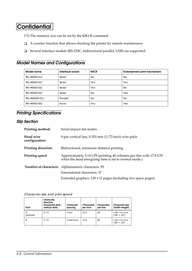
Model Names and Configurations
Printing Specifications
Slip Section
Model name Interface board MICR Endorsement print mechanism
TM-H6000-011 Serial No No
TM-H6000-021 Serial Yes Yes
TM-H6000-031 Serial Yes No
TM-H6000-041 Serial No Yes
TM-H6000P-011 Parallel No No
TM-H6000-051 None Yes Yes
Printing method: Serial impact dot matrix
Head wire configuration:
9-pin vertical line, 0.353 mm (1/72-inch) wire pitch
Printing direction: Bidirectional, minimum distance printing
Printing speed Approximately 5.14 LPS (printing 40 columns per line with 17.8 CPI when the head energizing time is set to normal mode.)
Number of characters: Alphanumeric characters: 95
International characters: 37
Extended graphics: 128 × 12 pages (including two space pages)
Character size and print speed
Font
Character structure (horizontal dots × vertical dots)
Character spacing
Characters per inch
Characters per line
Character size(width×height)
A (default)
5 × 9 1 dot 13.3 45 1.56 × 3.1 mm (.06" × .12")
B 7 × 9 2 half-dots 17.8 60 1.24 × 3.1 mm (.05" × .12")
General Information 1-3
TM-H6000/H6000P Developer’s GuideConfidentialReceipt Section
Printing method: Thermal line printing
Dot density: 180 dpi × 180 dpi [the number of dots per 25.4 mm (1”)]
Printing direction: Unidirectional with friction feed
Printing width: 72 mm (2.83”), 512 dot positions
Characters per line: 42 (font A, default) 56 (font B)
Character spacing: 0.28 mm (.01”) (2 dots) (font A, default)0.28 mm (.01”) (2 dots) (font B)Programmable by control command.
Print speed: 44 lines/second maximum (when the line spacing is set to 3.18 mm (1/8”), at 24V, 31° C (87.8° F) , density level 2)140 mm/second maximum (approximately 5.5”/second)Speed is switched automatically, depending on the voltage applied to the printer and the head temperature of the printer.
Paper feed speed: Approximately 140 mm/second (approximately 5.5”/second) continuous feeding
Line spacing (default): 4.23 mm (1/6”), programmable by control commands.
Number of characters: Alphanumeric characters: 95International characters: 37
Extended graphics: 128 × 11 pages (including one space page)
1-4 General Information
Confidential
* CPL = characters per line
* Space between characters is not included
* Characters can be scaled up to 64 times the standard size.
* When using Font B in a font mode such as emphasized mode, some words may be hard to read. Check the font mode in advance when using Font B.
Endorsement Section
Character structure: Font A: 12 × 24 (including 2-dot spacing in horizontal)
Font B: 9 × 17 (including 2-dot spacing in horizontal)
Font A is the default
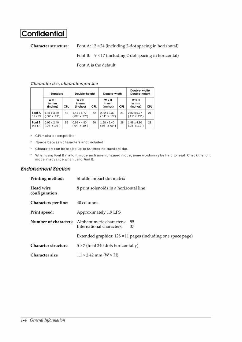
Character size, characters per line
Standard Double-height Double-widthDouble-width/Double-height
W x H in mm
(inches) CPL
W x H in mm
(inches) CPL
W x H in mm
(inches) CPL
W x H in mm
(inches) CPL
Font A12 x 24
1.41 x 3.39(.06” x .13”)
42 1.41 x 6.77(.06” x .27”)
42 2.82 x 3.39(.11” x .13”)
21 2.82 x 6.77(.11” x .27”)
21
Font B9 x 17
0.99 x 2.40(.04” x .09”)
56 0.99 x 4.80(.04” x .19”)
56 1.98 x 2.40(.08” x .09”)
28 1.98 x 4.80(.08” x .19”)
28
Printing method: Shuttle impact dot matrix
Head wire configuration
8 print solenoids in a horizontal line
Characters per line: 40 columns
Print speed: Approximately 1.9 LPS
Number of characters: Alphanumeric characters: 95International characters: 37
Extended graphics: 128 × 11 pages (including one space page)
Character structure 5 × 7 (total 240 dots horizontally)
Character size 1.1 × 2.42 mm (W × H)
General Information 1-5
TM-H6000/H6000P Developer’s GuideConfidentialConnectors
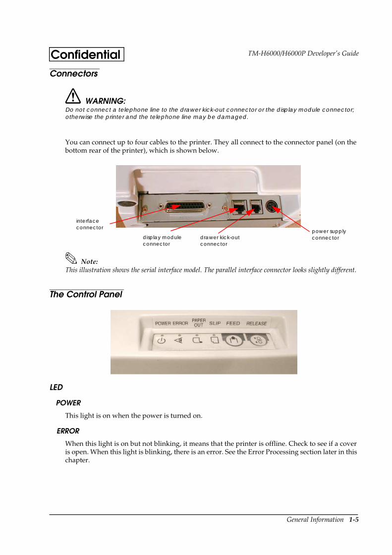
WARNING:Do not connect a telephone line to the drawer kick-out connector or the display module connector; otherwise the printer and the telephone line may be damaged.
You can connect up to four cables to the printer. They all connect to the connector panel (on the bottom rear of the printer), which is shown below.
Note:This illustration shows the serial interface model. The parallel interface connector looks slightly different.
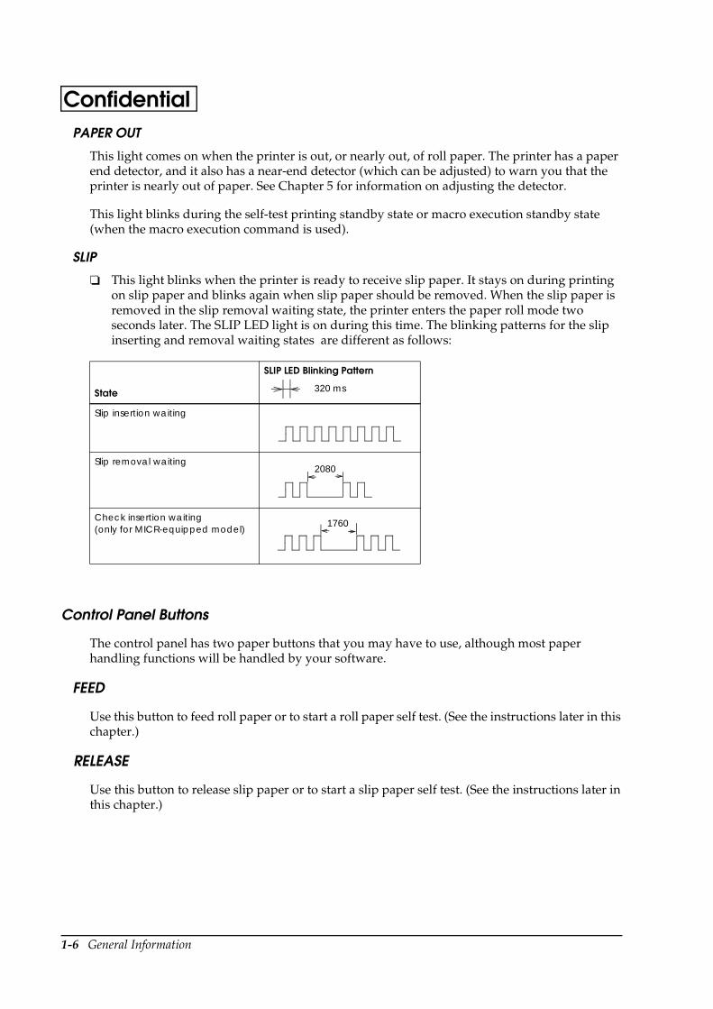
The Control Panel
LED
POWER
This light is on when the power is turned on.
ERROR
When this light is on but not blinking, it means that the printer is offline. Check to see if a cover is open. When this light is blinking, there is an error. See the Error Processing section later in this chapter.
interface connector
display module connector
drawer kick-out connector
power supply connector
1-6 General Information
ConfidentialPAPER OUT
This light comes on when the printer is out, or nearly out, of roll paper. The printer has a paper end detector, and it also has a near-end detector (which can be adjusted) to warn you that the printer is nearly out of paper. See Chapter 5 for information on adjusting the detector.
This light blinks during the self-test printing standby state or macro execution standby state (when the macro execution command is used).
SLIP
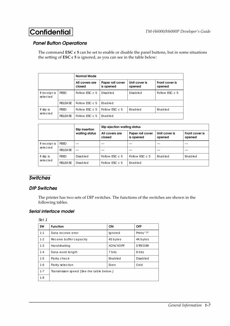
This light blinks when the printer is ready to receive slip paper. It stays on during printing on slip paper and blinks again when slip paper should be removed. When the slip paper is removed in the slip removal waiting state, the printer enters the paper roll mode two seconds later. The SLIP LED light is on during this time. The blinking patterns for the slip inserting and removal waiting states are different as follows:
Control Panel Buttons
The control panel has two paper buttons that you may have to use, although most paper handling functions will be handled by your software.
FEED
Use this button to feed roll paper or to start a roll paper self test. (See the instructions later in this chapter.)
RELEASE
Use this button to release slip paper or to start a slip paper self test. (See the instructions later in this chapter.)
State
SLIP LED Blinking Pattern
Slip insertion waiting
Slip removal waiting
Check insertion waiting (only for MICR-equipped model)
2080
1760
320 ms
General Information 1-7
TM-H6000/H6000P Developer’s GuideConfidentialPanel Button Operations
The command ESC c 5 can be set to enable or disable the panel buttons, but in some situations the setting of ESC c 5 is ignored, as you can see in the table below:
Switches
DIP Switches
The printer has two sets of DIP switches. The functions of the switches are shown in the following tables.
Serial interface model
Normal Mode
All covers are closed
Paper roll cover is opened
Unit cover is opened
Front cover is opened
If receipt is selected
FEED Follow ESC c 5 Disabled Disabled Follow ESC c 5
RELEASE Follow ESC c 5 Enabled
If slip is selected
FEED Follow ESC c 5 Follow ESC c 5 Enabled Enabled
RELEASE Follow ESC c 5 Enabled
Slip insertion waiting status
Slip ejection waiting status
All covers are closed
Paper roll cover is opened
Unit cover is opened
Front cover is opened
If receipt is selected
FEED — — — — —
RELEASE — — — — —
If slip is selected
FEED Disabled Follow ESC c 5 Follow ESC c 5 Enabled Enabled
RELEASE Disabled Follow ESC c 5 Enabled
Set 1
SW Function ON OFF
1-1 Data receive error Ignored Prints “?”
1-2 Receive buffer capacity 45 bytes 4K bytes
1-3 Handshaking XON/XOFF DTR/DSR
1-4 Data word length 7 bits 8 bits
1-5 Parity check Enabled Disabled
1-6 Parity selection Even Odd
1-7 Transmission speed (See the table below.)
1-8
1-8 General Information
Confidential
Print density
Notes:
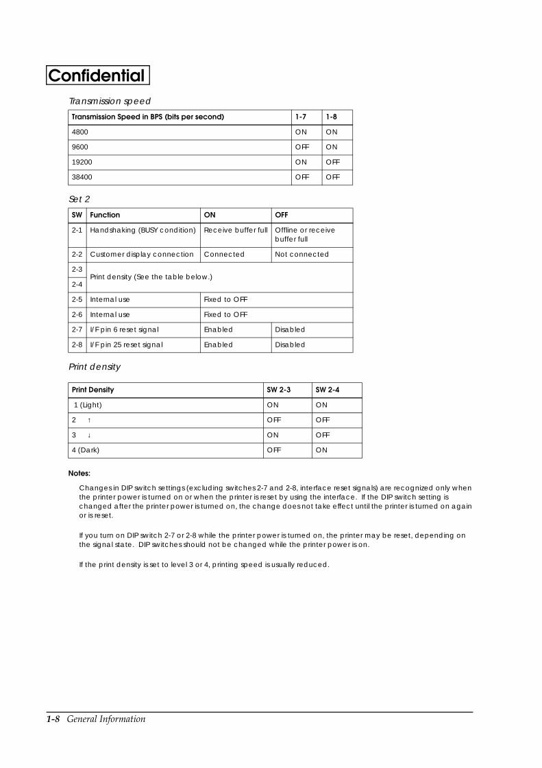
Changes in DIP switch settings (excluding switches 2-7 and 2-8, interface reset signals) are recognized only when the printer power is turned on or when the printer is reset by using the interface. If the DIP switch setting is changed after the printer power is turned on, the change does not take effect until the printer is turned on again or is reset.
If you turn on DIP switch 2-7 or 2-8 while the printer power is turned on, the printer may be reset, depending on the signal state. DIP switches should not be changed while the printer power is on.
If the print density is set to level 3 or 4, printing speed is usually reduced.
Transmission speed
Transmission Speed in BPS (bits per second) 1-7 1-8
4800 ON ON
9600 OFF ON
19200 ON OFF
38400 OFF OFF
Set 2
SW Function ON OFF
2-1 Handshaking (BUSY condition) Receive buffer full Offline or receive buffer full
2-2 Customer display connection Connected Not connected
2-3Print density (See the table below.)
2-4
2-5 Internal use Fixed to OFF
2-6 Internal use Fixed to OFF
2-7 I/F pin 6 reset signal Enabled Disabled
2-8 I/F pin 25 reset signal Enabled Disabled
Print Density SW 2-3 SW 2-4
1 (Light) ON ON
2 ↑ OFF OFF
3 ↓ ON OFF
4 (Dark) OFF ON
General Information 1-9
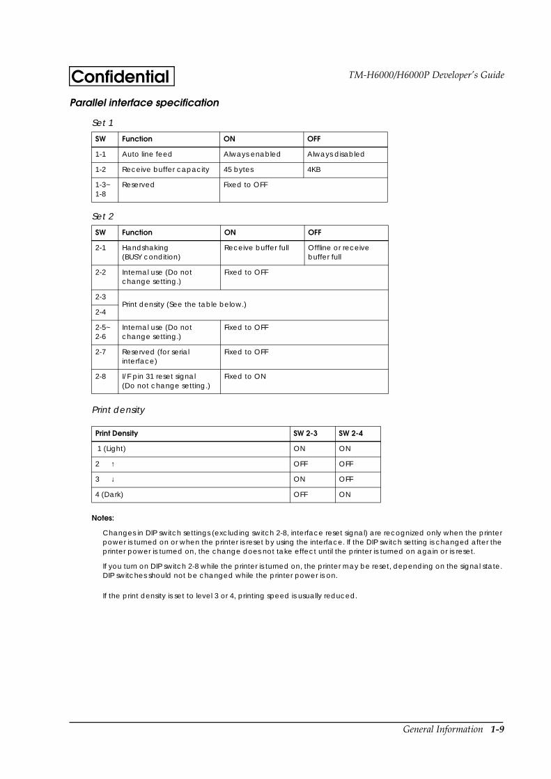
TM-H6000/H6000P Developer’s GuideConfidentialParallel interface specification
Print density
Notes:
Changes in DIP switch settings (excluding switch 2-8, interface reset signal) are recognized only when the printer power is turned on or when the printer is reset by using the interface. If the DIP switch setting is changed after the printer power is turned on, the change does not take effect until the printer is turned on again or is reset.
If you turn on DIP switch 2-8 while the printer is turned on, the printer may be reset, depending on the signal state. DIP switches should not be changed while the printer power is on.
If the print density is set to level 3 or 4, printing speed is usually reduced.
Set 1
SW Function ON OFF
1-1 Auto line feed Always enabled Always disabled
1-2 Receive buffer capacity 45 bytes 4KB
1-3~1-8
Reserved Fixed to OFF
Set 2
SW Function ON OFF
2-1 Handshaking(BUSY condition)
Receive buffer full Offline or receive buffer full
2-2 Internal use (Do not change setting.)
Fixed to OFF
2-3Print density (See the table below.)
2-4
2-5~2-6
Internal use (Do not change setting.)
Fixed to OFF
2-7 Reserved (for serial interface)
Fixed to OFF
2-8 I/F pin 31 reset signal(Do not change setting.)
Fixed to ON
Print Density SW 2-3 SW 2-4
1 (Light) ON ON
2 ↑ OFF OFF
3 ↓ ON OFF
4 (Dark) OFF ON
1-10 General Information
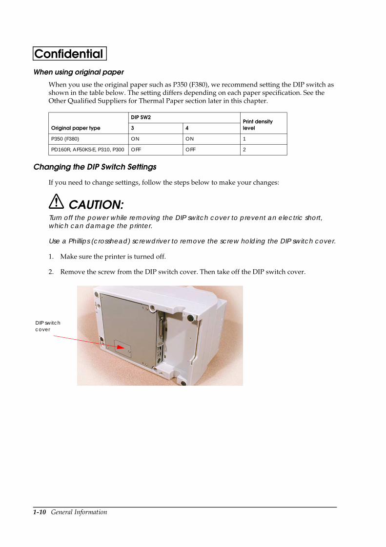
ConfidentialWhen using original paper
When you use the original paper such as P350 (F380), we recommend setting the DIP switch as shown in the table below. The setting differs depending on each paper specification. See the Other Qualified Suppliers for Thermal Paper section later in this chapter.
Changing the DIP Switch Settings
If you need to change settings, follow the steps below to make your changes:
CAUTION:Turn off the power while removing the DIP switch cover to prevent an electric short, which can damage the printer.
Use a Phillips (crosshead) screwdriver to remove the screw holding the DIP switch cover.
1. Make sure the printer is turned off.
2. Remove the screw from the DIP switch cover. Then take off the DIP switch cover.
Original paper type
DIP SW2Print density level3 4
P350 (F380) ON ON 1
PD160R, AF50KS-E, P310, P300 OFF OFF 2
DIP switch cover
General Information 1-11
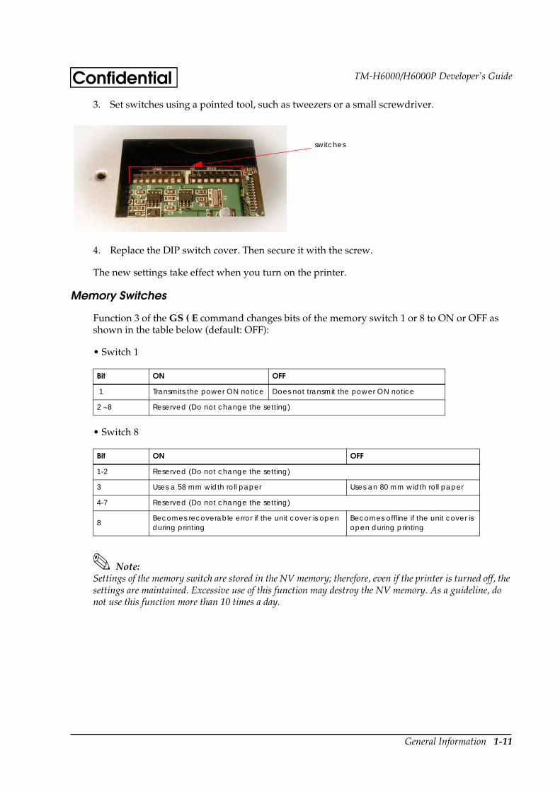
TM-H6000/H6000P Developer’s GuideConfidential3. Set switches using a pointed tool, such as tweezers or a small screwdriver.
4. Replace the DIP switch cover. Then secure it with the screw.
The new settings take effect when you turn on the printer.
Memory Switches
Function 3 of the GS ( E command changes bits of the memory switch 1 or 8 to ON or OFF as shown in the table below (default: OFF):
• Switch 1
• Switch 8
Note:Settings of the memory switch are stored in the NV memory; therefore, even if the printer is turned off, the settings are maintained. Excessive use of this function may destroy the NV memory. As a guideline, do not use this function more than 10 times a day.
Bit ON OFF
1 Transmits the power ON notice Does not transmit the power ON notice
2 ~8 Reserved (Do not change the setting)
Bit ON OFF
1-2 Reserved (Do not change the setting)
3 Uses a 58 mm width roll paper Uses an 80 mm width roll paper
4-7 Reserved (Do not change the setting)
8Becomes recoverable error if the unit cover is open during printing
Becomes offline if the unit cover is open during printing
switches
1-12 General Information
ConfidentialError Processing
Error Types
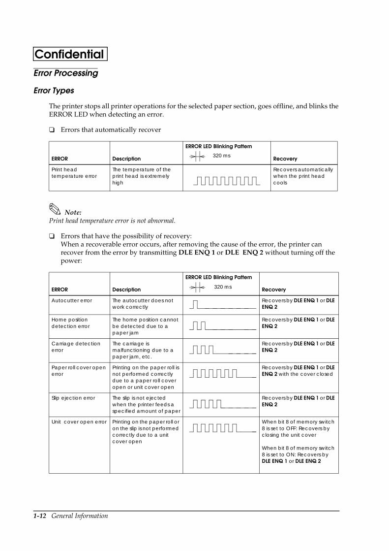
The printer stops all printer operations for the selected paper section, goes offline, and blinks the ERROR LED when detecting an error.
Errors that automatically recover
Note:Print head temperature error is not abnormal.
Errors that have the possibility of recovery: When a recoverable error occurs, after removing the cause of the error, the printer can recover from the error by transmitting DLE ENQ 1 or DLE ENQ 2 without turning off the power:
ERROR Description
ERROR LED Blinking Pattern
Recovery
Print head temperature error
The temperature of the print head is extremely high
Recovers automatically when the print head cools
ERROR Description
ERROR LED Blinking Pattern
Recovery
Autocutter error The autocutter does not work correctly
Recovers by DLE ENQ 1 or DLE ENQ 2
Home position detection error
The home position cannot be detected due to a paper jam
Recovers by DLE ENQ 1 or DLE ENQ 2
Carriage detection error
The carriage is malfunctioning due to a paper jam, etc.
Recovers by DLE ENQ 1 or DLE ENQ 2
Paper roll cover open error
Printing on the paper roll is not performed correctly due to a paper roll cover open or unit cover open
Recovers by DLE ENQ 1 or DLE ENQ 2 with the cover closed
Slip ejection error The slip is not ejected when the printer feeds a specified amount of paper
Recovers by DLE ENQ 1 or DLE ENQ 2
Unit cover open error Printing on the paper roll or on the slip is not performed correctly due to a unit cover open
When bit 8 of memory switch 8 is set to OFF: Recovers by closing the unit cover
When bit 8 of memory switch 8 is set to ON: Recovers by DLE ENQ 1 or DLE ENQ 2
320 ms
320 ms
General Information 1-13
TM-H6000/H6000P Developer’s GuideConfidentialSee Chapter 5 for removing a paper jam.
Note:When the printer recovers from an error using DLE ENQ 1 while slip paper is selected, the printer first ejects the slip, then loads paper. However, when the printer recovers from a slip ejection error, the printer only ejects the slip and does not load paper.
When the printer recovers from an error using DLE ENQ 2 while slip paper is selected, the printer ejects the slip.
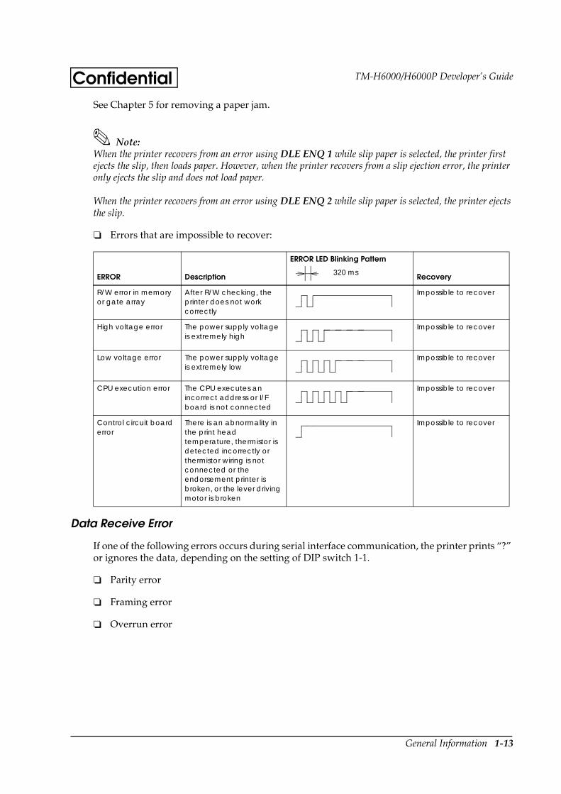
Errors that are impossible to recover:
Data Receive Error
If one of the following errors occurs during serial interface communication, the printer prints “?” or ignores the data, depending on the setting of DIP switch 1-1.
Parity error
Framing error
Overrun error
ERROR Description
ERROR LED Blinking Pattern
Recovery
R/W error in memory or gate array
After R/W checking, the printer does not work correctly
Impossible to recover
High voltage error The power supply voltage is extremely high
Impossible to recover
Low voltage error The power supply voltage is extremely low
Impossible to recover
CPU execution error The CPU executes an incorrect address or I/F board is not connected
Impossible to recover
Control circuit board error
There is an abnormality in the print head temperature, thermistor is detected incorrectly or thermistor wiring is not connected or the endorsement printer is broken, or the lever driving motor is broken
Impossible to recover
320 ms
1-14 General Information
ConfidentialSensors
Paper Sensors
Receipt section
Paper roll near-end sensor:
• The sensor is located on the roll paper supply device on the receipt section. It detects the near-end of the paper roll by detecting the paper roll diameter. You can adjust the sensor. See Chapter 5 for details on adjustment.
• When the printer detects a paper near-end, it either stops or continues printing, depending on the ESC c 4 setting.
• When the sensor is selected to stop printing, the sensor detects a paper near-end and the printer automatically goes offline after printing the current line. To restart printing, load the paper and set the printer back online by closing the printer cover. The printer starts initializing and continues printing data stored in the print buffer.
Paper roll end sensor:
• The paper roll end sensor is located in the paper path on the receipt section. It detects the presence of paper in the paper path of the printer mechanism.
• When there is no paper in the paper path, the PAPER OUT LED lights.
• When the sensor detects a paper end, printing stops even if it is in the middle of one transaction; therefore, it is recommended to use the paper roll near-end sensor and use the paper end sensor as a supplement.
Slip section
TOF (Top of Form) sensor: The slip TOF sensor is located in the slip paper path and detects the presence of slip paper in the paper path. The SLIP LED lights accordingly.
BOF (Bottom of Form) sensor:
• The sensor is located in the slip entrance and detects whether the paper is inserted correctly and whether it is removed or not. The printer does not proceed to the next operation until the paper has been set correctly or removed. (The SLIP LED continues blinking.)
• When the printer detects a paper end, it either stops or continues printing, depending on the ESC c 4 setting.
• When the sensor is selected to stop printing, the sensor detects a paper-end and the printer prints data up to the end of the printable area, ejects the slip when all the next print data is transmitted, and then waits for the slip to be removed. After the slip is removed, the printer enters the paper insertion waiting state.
General Information 1-15
TM-H6000/H6000P Developer’s GuideConfidential Slip eject sensor:
• The slip eject sensor is located in the slip paper exit and detects whether the paper is removed or not after printing. The printer does not proceed to the next operation until the paper has been removed.
Printer Cover Sensors
Receipt section
Paper roll cover open sensor:
• When a paper roll is selected as the print sheet, if the sensor detects a cover open during printing, the printer goes offline, stops printing immediately, and the ERROR LED blinks. Even if the cover is closed, the ERROR LED still blinks. You need to transmit the DLE ENQ command to recover.
If the printer continues printing, it starts printing from the beginning of the line where an error occurred; therefore, double printing or printing position shift may occur. It is recommended to clear the buffers and resend the print data.
• When a slip is selected as the print sheet, if the sensor detects a cover open during printing, the printer finishes printing data for the line when the cover open is detected, then stops the carriage movement and goes offline. The printer goes online when the cover is closed and restarts printing.
Note:Whether the cover is open or not does not affect the status reported by the paper roll end sensor.
When the printer is in the waiting status, the printer mechanism is initialized if the cover is opened and closed. Do not open/close the cover during printing, which may cause an error. Be sure not to open the cover during autocutter operation, which may damage the printer.
Unit cover open sensor:
• When the sensor detects a unit cover open during printing, the printer goes offline depending on the setting of bit 8 for the memory switch.
The default is that the printer finishes printing data for the line when the cover open is detected and stops printing. The printer goes online when the cover is closed and restarts printing.
If a recoverable error is selected by memory switch, the printer goes offline, stops printing immediately and the ERROR LED blinks. Even if the cover is closed, the ERROR LED still blinks. You need to transmit the DLE ENQ command to recover. If the printer continues printing, it starts printing from the beginning of the line where an error occurred. In this case, double printing or printing position shift may occur. It is recommended to clear the buffers and resend the print data.
1-16 General Information
ConfidentialSlip section
Front cover open sensor:
• When the sensor detects a cover open during printing, the printer finishes printing data for the line when the cover open is detected; then stops the carriage movement and goes offline. The printer goes online when the cover is closed and restarts printing.
Self Tests
The self tests let you know if your printer is operating properly. There are self tests for both roll paper and slip paper. They check the control circuits, printer mechanisms, print quality, control software version, and DIP switch settings.
These tests are independent of any other equipment or software, so it is a good idea to run them when you first set up the printer and if you have any trouble. If the self tests work correctly, the problem is in the other equipment or the software, not the printer.
Running the Self Test on the Paper Roll
1. Make sure the printer is turned off and the printer cover is closed properly.
2. While holding down the FEED button, turn on the printer using the switch on the front of the printer. The self test prints the printer settings and then prints the following, cuts the paper, and pauses. (The PAPER OUT light blinks.)
If you want to continue SELF-TEST printing, Please press the FEED button.
3. Press the FEED button to continue printing. The printer prints a pattern using the built-in character set.
4. The self test automatically ends and cuts the paper after printing the following:
*** completed ***
The printer is ready to receive data as soon as it completes the self test.
Note:If you want to pause the self test manually, press the FEED button. Press the FEED button again to continue the self test.
Running the Self Test with Slip Paper
1. Make sure the printer is turned off and the printer cover is closed properly.
2. While holding down the RELEASE button, turn on the printer using the switch on the front of the printer. (The SLIP light blinks.)
General Information 1-17
TM-H6000/H6000P Developer’s GuideConfidential3. Feed a sheet of slip paper into the printer. The printer loads the paper automatically, prints
the printer settings, and then ejects the paper. (The SLIP light blinks.)
4. Remove the paper from the printer and feed another sheet of slip paper into the printer to print characters from the character table. Continue to feed slip paper into the printer until the self test prints the following:
***completed***
The printer is ready to receive data as soon as it completes the self test.
Running the Self Test with the Optional Endorsement Function
If your printer has the optional endorsement function, the slip paper self test is slightly different. When you feed additional sheets of slip paper in step 4, two lines are printed on the back of the slip by the endorsement print mechanism; then the test continues printing on the surface side of the slip as described above.
Hexadecimal Dump
This feature allows experienced users to see exactly what data is coming to the printer. This can be useful in finding software problems. When you turn on the hex dump function, the printer prints all commands and other data in hexadecimal format, along with a guide section to help you find specific commands.
To use the hex dump feature, follow these steps:
1. After you make sure the printer is off, open the paper roll cover.
2. Hold down the FEED button while you turn on the printer to print on roll paper or hold down the RELEASE button to print on the surface side of a slip or execute the GS ( A command.
3. Close the cover.
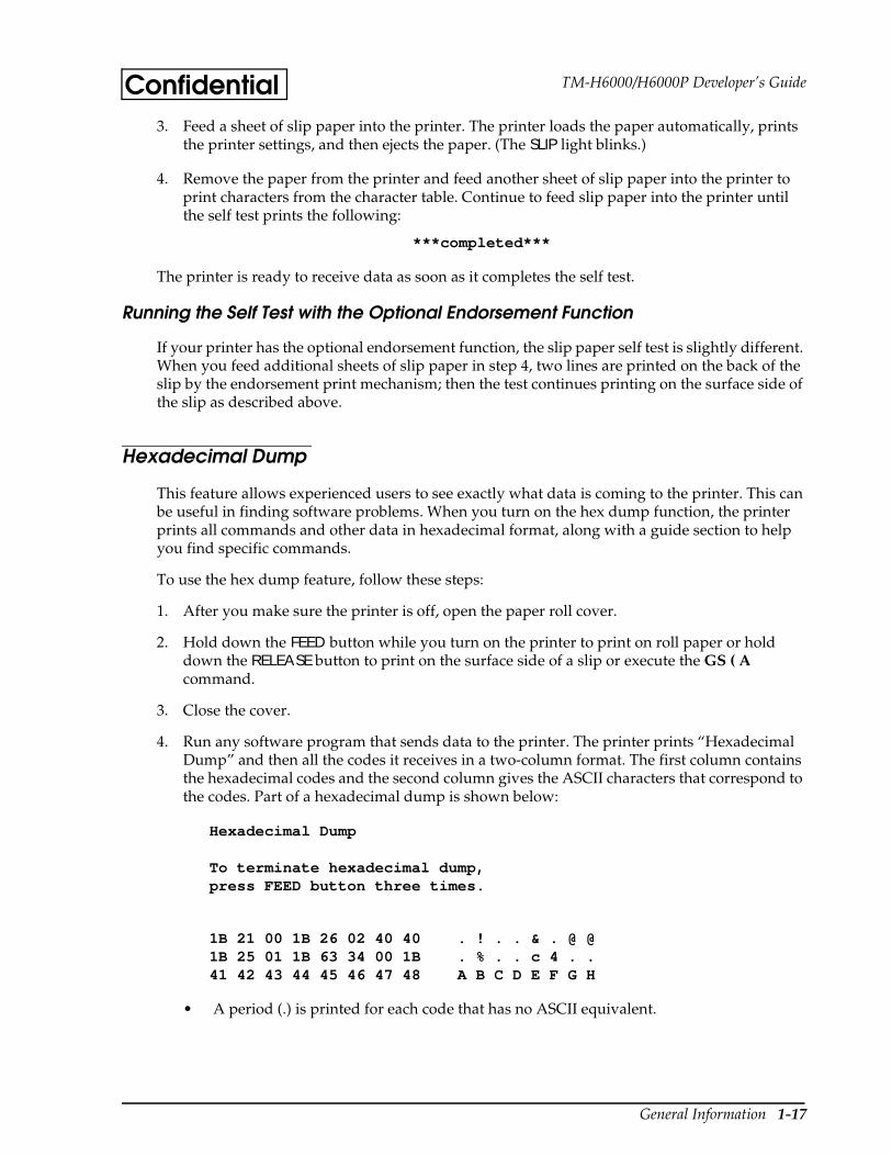
4. Run any software program that sends data to the printer. The printer prints “Hexadecimal Dump” and then all the codes it receives in a two-column format. The first column contains the hexadecimal codes and the second column gives the ASCII characters that correspond to the codes. Part of a hexadecimal dump is shown below:
Hexadecimal Dump
To terminate hexadecimal dump,press FEED button three times.
1B 21 00 1B 26 02 40 40 . ! . . & . @ @1B 25 01 1B 63 34 00 1B . % . . c 4 . .41 42 43 44 45 46 47 48 A B C D E F G H
• A period (.) is printed for each code that has no ASCII equivalent.
1-18 General Information
Confidential• In hex dump mode all commands except DLE EOT, DLE ENQ, and DLE DC4 are
disabled.
5. Open the cover to set the printer offline so that it will print the last line.
6. Close the cover and turn off the printer, press the FEED button three times, or reset the printer to turn off the hex dump mode.
Standard Parts Included with the Printer
User’s Manual
Paper roll
Hex screws
Control panel label
Power switch cover (using this cover enables you to prevent accidental turning off the power)
Ribbon cassette ERC-32(P)
Endorsement ribbon cassette (for printers equipped with the optional endorsement print mechanism)
Options
EPSON power supply unit, PS-170
MICR reader (factory-installed option) (available only for serial interface model)
Endorsement printer (factory-installed option) (required for use with MICR)
Direct connection customer display DM-D105/D205 or DM-D106/DM-D206 (available only for serial interface model)
Paper-width variable plate for 58 mm or 60 mm (2.3 or 2.4 “)
Consumables
Ribbons
EPSON ribbon cassette, ERC-32 (P)
EPSON ribbon cassette ERC-41 (P) (for the optional endorsement print mechanism)
General Information 1-19
TM-H6000/H6000P Developer’s GuideConfidentialThermal Paper
Thermal paper is available from the supplier in your area.
Specified Thermal Paper: NTP080-80
In Japan: Nakagawa Seisakujo2-5-21 Nishiki-Cho Warabi-ShiSaitama-Ken 335 JapanTel: (048) 444-8211Fax: (048) 443-6652
In USA: Nakagawa Mfg (USA) Inc.2305 Lincoln AvenueHayward, CA 94545 USATel: (510) 782-0197Fax: (510) 782-7124
In Europe: Nakagawa Mfg (Europe) GmbHKrützpoort 16, 47804Krefeld, GermanyTel: 02151-711051Fax: 02151-713293
In Southeast Asia: N.A.K. Mfg (Malaysia) SDN BHDLot 19-11, Bersatu Industrial Complexs,Jalan Satu, Kaw Per. Cheras Jaya,Balakong Industrial Area, 43200 Cheras.Selangor Darul Ehsan, MalaysiaTel: 03-9047896, 9047900, 9047691Fax: 03-9047889
Original paper: TF50KS-ENippon Paper Industry Co., Ltd.1-12-1, Yuraku-Cho, Chiyoda-KuTokyo 100 JapanTel: 03-3218-8000Fax: 03-3216-1375
Other Qualified Suppliers for Thermal Paper
The following suppliers sell thermal paper that may be used if desired. Contact each company for information.
Original paper: PD 160RNew Oji Paper Mfg. Co., Ltd.7-5 Ginza 4-Chome Chuo-KuTokyo 104 JapanTel: 03-3563-4800Fax: 03-3563-1136
1-20 General Information
ConfidentialOriginal paper: AF50KS-E
Jujo Thermal Oy (Finland)P.O. Box 92 FIN27501 Kauttua FinlandTel: 38-3932900Fax: 38-3932419
Original paper: P350(F380), P310, P300Kanzaki Specialty Papers, Inc.1500 Main StreetSpringfield, MA 01115 USATel: (413) 736-3216Fax: (413) 734-5101
Hardware 2-1
TM-H6000/H6000P Developer’s GuideConfidentialChapter 2Hardware
General Specifications
Slip Printer Section
Printing Specifications
Character Specifications
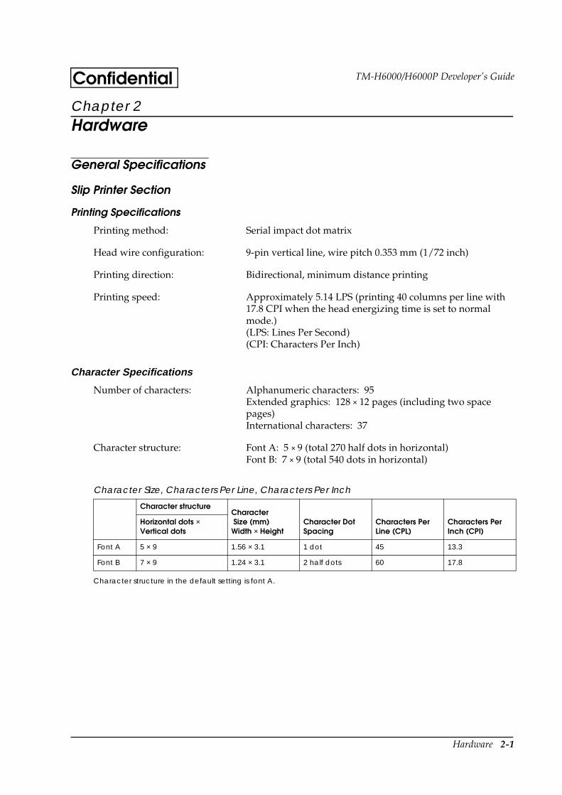
Character structure in the default setting is font A.
Printing method: Serial impact dot matrix
Head wire configuration: 9-pin vertical line, wire pitch 0.353 mm (1/72 inch)
Printing direction: Bidirectional, minimum distance printing
Printing speed: Approximately 5.14 LPS (printing 40 columns per line with 17.8 CPI when the head energizing time is set to normal mode.)(LPS: Lines Per Second)(CPI: Characters Per Inch)
Number of characters: Alphanumeric characters: 95Extended graphics: 128 × 12 pages (including two space pages)International characters: 37
Character structure: Font A: 5 × 9 (total 270 half dots in horizontal)Font B: 7 × 9 (total 540 dots in horizontal)
Character Size, Characters Per Line, Characters Per Inch
Character structureCharacter Size (mm)Width × Height
Character Dot Spacing
Characters Per Line (CPL)
Characters Per Inch (CPI)
Horizontal dots × Vertical dots
Font A 5 × 9 1.56 × 3.1 1 dot 45 13.3
Font B 7 × 9 1.24 × 3.1 2 half dots 60 17.8

2-2 Hardware
Confidential
Character structure
Paper Specifications
1. Cut sheet
Paper type: Normal paper, pressure-sensitive paper, carbon copy paper
Paper size: 70 - 148 mm (W) × 150 - 210 mm (L) (2.8 - 5.8”(W) × 5.9 - 8.3”(L))
Copy capability and paper thickness:
• Normal paper (single-ply): 0.09 to 0.2 mm (0.0035 to 0.0079 in.)
• Carbon copy papercombination: 4 sheets maximum (original + 2 copies)
5 × 9 Font Sample (Font A)
∗1: Character pitch
Alphanumeric and international characters Graphics
3.1 mm(.122”)
1.88 mm(.074”)1.90 mm(.075”) (∗1)
2.4 mm(.095”)
.353 mm(.014”)
.317 mm(.012”)
1.56 mm (0.61”)
7 × 9 Font Sample (Font B)
∗1: Character pitch
Alphanumeric andinternational characters
Graphics
3.1 mm(.122”)
1.56 mm(.061”)(∗1)1.43 mm(.056”).159 mm
(.006”)
1.24 mm(.049”)
0.353 mm(.014”)
2.4 mm(.095”)
Hardware 2-3
TM-H6000/H6000P Developer’s GuideConfidential
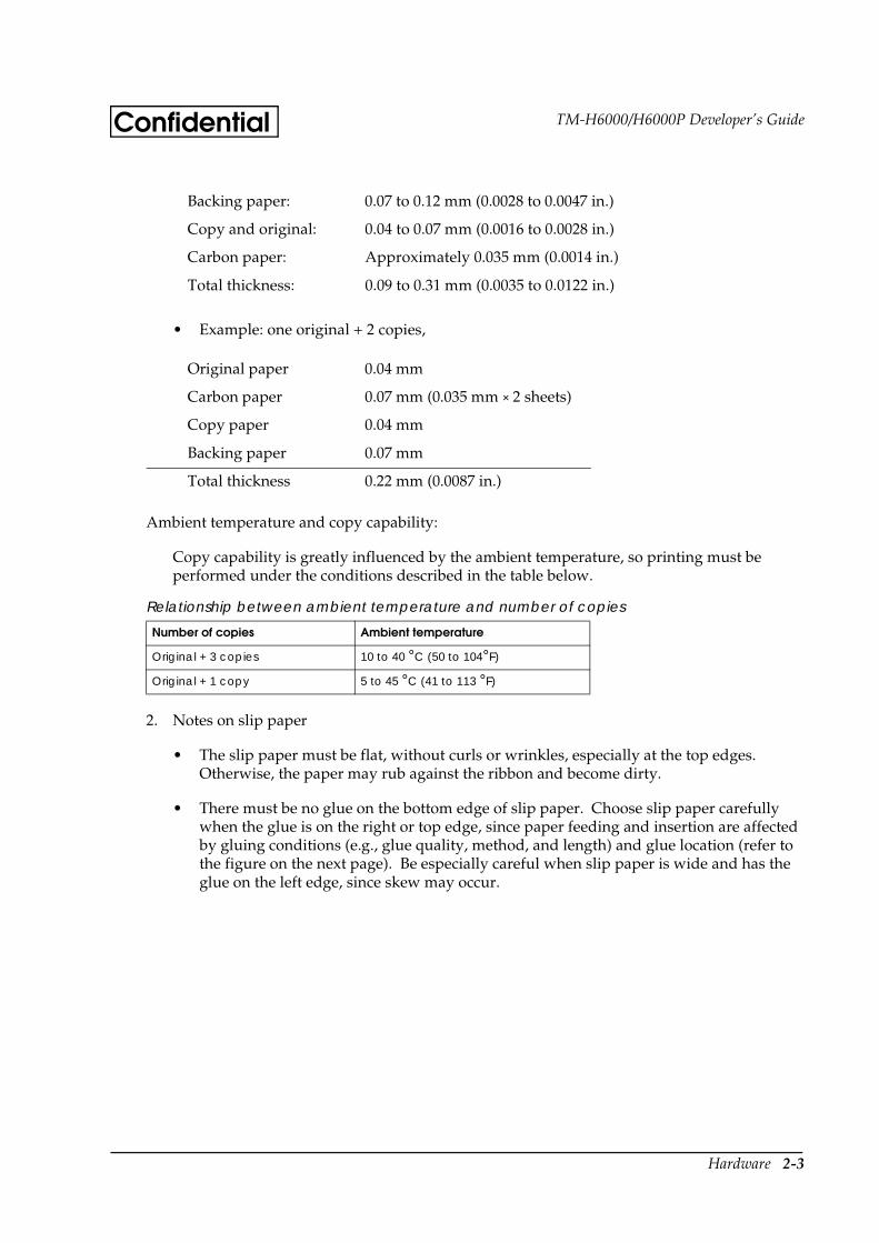
• Example: one original + 2 copies,
Ambient temperature and copy capability:
Copy capability is greatly influenced by the ambient temperature, so printing must be performed under the conditions described in the table below.
2. Notes on slip paper
• The slip paper must be flat, without curls or wrinkles, especially at the top edges. Otherwise, the paper may rub against the ribbon and become dirty.
• There must be no glue on the bottom edge of slip paper. Choose slip paper carefully when the glue is on the right or top edge, since paper feeding and insertion are affected by gluing conditions (e.g., glue quality, method, and length) and glue location (refer to the figure on the next page). Be especially careful when slip paper is wide and has the glue on the left edge, since skew may occur.
Backing paper: 0.07 to 0.12 mm (0.0028 to 0.0047 in.)
Copy and original: 0.04 to 0.07 mm (0.0016 to 0.0028 in.)
Carbon paper: Approximately 0.035 mm (0.0014 in.)
Total thickness: 0.09 to 0.31 mm (0.0035 to 0.0122 in.)
Original paper 0.04 mm
Carbon paper 0.07 mm (0.035 mm × 2 sheets)
Copy paper 0.04 mm
Backing paper 0.07 mm
Total thickness 0.22 mm (0.0087 in.)
Relationship between ambient temperature and number of copies
Number of copies Ambient temperature
Original + 3 copies 10 to 40 °C (50 to 104°F)
Original + 1 copy 5 to 45 °C (41 to 113 °F)

2-4 Hardware
Confidential
Slip paper glued area
• Since the slip BOF sensor uses a photo sensor, do not use paper that has holes at the sensor position, or is translucent.
• Since the slip TOF sensor uses a reflective photo sensor and it detects from the back of slip paper, do not use paper that has holes or dark portions with low reflection (less than 40% reflection) at the sensor position.
• Since the slip paper ejection sensor uses a reflective photo sensor and it detects from the surface of the paper roll, do not use paper that has holes or dark portions with low reflection (less than 40% reflection) at the sensor position.
• Use thinner paper (N30 or equivalent) between the top and bottom sheets of multi-ply paper. If thick paper is used, the copy capability is lowered.
Prohibited area for paper holes and low reflection
Paper feeddirection
Glued area
Use carefullyUse carefullyDo not useOK to use
15
30
20
10
Paper feed direction
Paper holes andtranslucence prohibited inthis area.
Area where paper holes areprohibited and reflection ratefor the surface on papershould be 40% or more.
Area where paper holes areprohibited and reflection ratefor the back on paper shouldbe 40% or more.
[Units: mm (All the numeric values are typical.)]
Hardware 2-5
TM-H6000/H6000P Developer’s GuideConfidentialPrintable Area
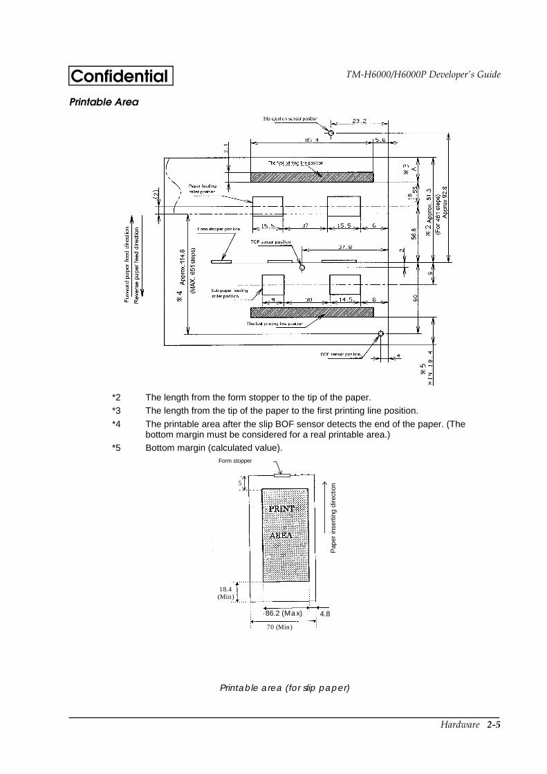
Printable area (for slip paper)
*2 The length from the form stopper to the tip of the paper.
*3 The length from the tip of the paper to the first printing line position.
*4 The printable area after the slip BOF sensor detects the end of the paper. (Thebottom margin must be considered for a real printable area.)
*5 Bottom margin (calculated value).
5.6
70 (Min)
85.4 (Max)
18.4(Min)
5
Form stopper
Pap
er in
sert
ing
dire
ctio
n
4.886.2 (Max)
2-6 Hardware
ConfidentialRibbon Cassette
Exclusive ribbon cassette for slip
E/P Endorsement Print Mechanism Section (Factory-Installed Option)
The endorsement print mechanism enables printing of endorsements as part of a sequence that is automatically processed: MICR reading, printing an endorsement on the back side of the personal check, and printing on the surface of it.
Printing Specifications
Character Specifications
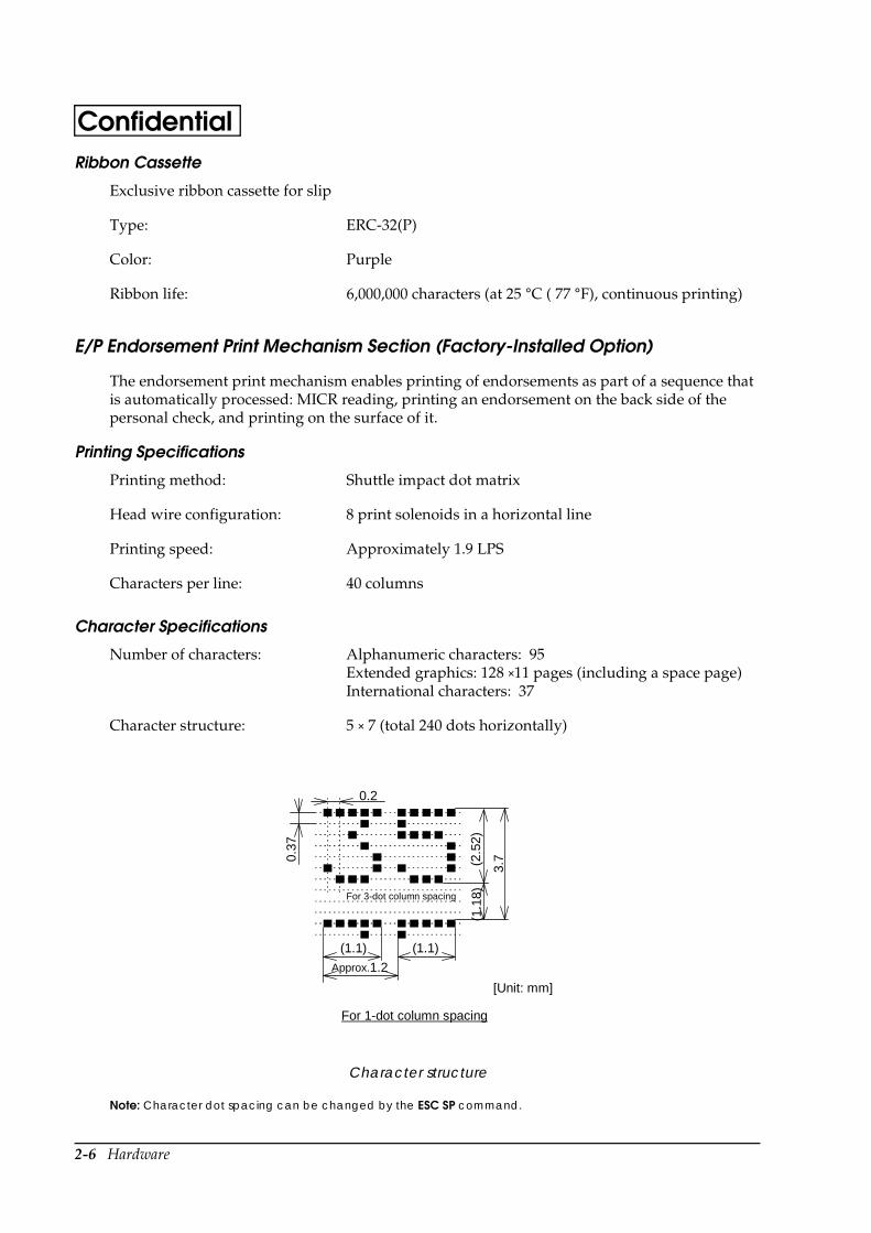
Character structure
Note: Character dot spacing can be changed by the ESC SP command.
Type: ERC-32(P)
Color: Purple
Ribbon life: 6,000,000 characters (at 25 °C ( 77 °F), continuous printing)
Printing method: Shuttle impact dot matrix
Head wire configuration: 8 print solenoids in a horizontal line
Printing speed: Approximately 1.9 LPS
Characters per line: 40 columns
Number of characters: Alphanumeric characters: 95Extended graphics: 128 ×11 pages (including a space page)International characters: 37
Character structure: 5 × 7 (total 240 dots horizontally)
(1.1)
For 3-dot column spacing
For 1-dot column spacing
(1.1
8)
0.2
Approx.1.2
(1.1)
[Unit: mm]
(2.5
2)
3.70.
37
Hardware 2-7
TM-H6000/H6000P Developer’s GuideConfidentialPaper Specifications
Cut sheet
Printable Area
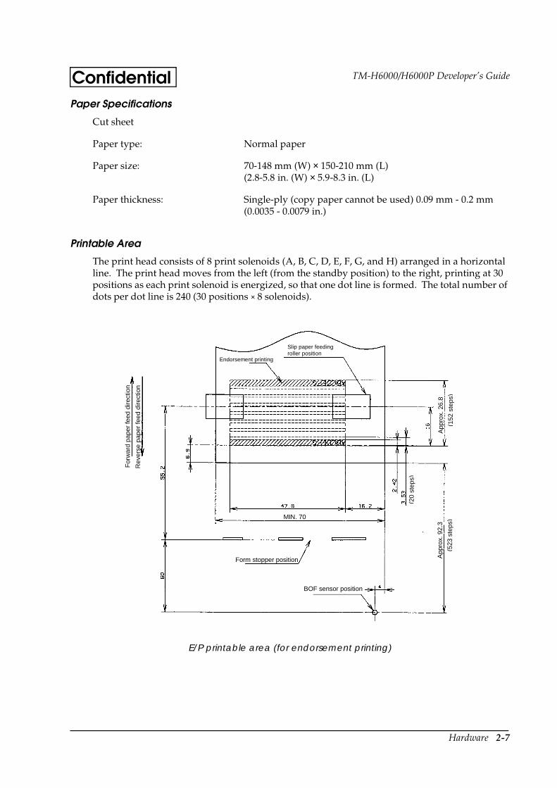
The print head consists of 8 print solenoids (A, B, C, D, E, F, G, and H) arranged in a horizontal line. The print head moves from the left (from the standby position) to the right, printing at 30 positions as each print solenoid is energized, so that one dot line is formed. The total number of dots per dot line is 240 (30 positions × 8 solenoids).
E/P printable area (for endorsement printing)
Paper type: Normal paper
Paper size: 70-148 mm (W) × 150-210 mm (L)(2.8-5.8 in. (W) × 5.9-8.3 in. (L)
Paper thickness: Single-ply (copy paper cannot be used) 0.09 mm - 0.2 mm (0.0035 - 0.0079 in.)
BOF sensor position
Form stopper position
MIN. 70
For
war
d pa
per
feed
dire
ctio
n
Rev
erse
pap
er fe
ed d
irect
ion
Endorsement printing
Slip paper feedingroller position
App
rox.
92.
3
(523
ste
ps)
(20
step
s)
App
rox.
26.
8
(152
ste
ps)

2-8 Hardware
ConfidentialRibbon Cassette
Exclusive ribbon cassette for E/P
Notes on Using the Endorsement Print Mechanism
The endorsement print mechanism (abbreviated as E/P) enables printing of endorsements as part of a sequence that is automatically processed: MICR reading, printing an endorsement on the back side of a personal check, and printing on the surface of it. Once the end of the paper exceeds the E/P print head position, reverse paper feeding to the front side is not possible.
When the endorsement printing is executed after a MICR reading, the printer feeds the paper forward automatically after receiving a command to print the endorsement; then the printer starts printing up to approximately 7.0 mm (0.28 in.) from the end of the check paper by using reverse paper feeding.
Since the E/P printing format is assumed to print an endorsement on a U.S. personal check, the print begins on the back side of the paper. (As viewed from the front of the printer, the endorsement printing characters are upside down.)
The printing sequence for slip paper is different, depending on whether an endorsement print mechanism is installed. That is, when the E/P is installed, once the printing exceeds the E/P printable area and the slip paper is fed forward, reverse paper feeding must be prohibited. Consider this when developing application programs.
The E/P printing must be not performed on copy paper. Otherwise, a paper jam may occur or the E/P may be broken. Because E/P printing feeds the paper in a reverse paper feed direction, the paper may be wrinkled.
In some case paper feeding may not be accurate when E/P printing is performed on check paper. This may depend on the width of the check paper. Therefore, it is recommended for the user to check in advance whether the check paper prints correctly or not.
Receipt Section
Printing Specifications
Type: ERC-41 (P)
Color: Purple
Ribbon life: 1,000,000 characters (at 25 °C (77 °F), continuous printing)
Printing method: Thermal line printing
Dot density: 180 dpi × 180 dpi. The number of dots per 25.4 mm (1")
Printing direction: Unidirectional with friction feed
Printing width: 72 mm (2.83"), 512 dot positions
Hardware 2-9
TM-H6000/H6000P Developer’s GuideConfidential
Character Specifications
• Space between characters is not included.
• Characters can be scaled up to 64 times the standard sizes.
• When using Font B with a font mode such as emphasized, some words may be hard to read. Check the font mode in advance when using Font B.
CPL = Characters per line
Autocutter
Partial cut: Cutting with one point left uncut
NOTES: 1. To prevent dot displacement, after cutting, feed paper approximately 1 mm (14/360 inches) or more before printing.
2. If the printer is stopped, you must feed paper over 40 mm (1.58 in.) before cutting
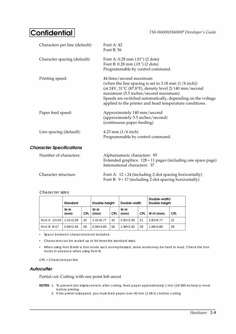
Characters per line (default): Font A: 42Font B: 56
Character spacing (default): Font A: 0.28 mm (.01") (2 dots)Font B: 0.28 mm (.01") (2 dots)Programmable by control command.
Printing speed: 44 lines/second maximum (when the line spacing is set to 3.18 mm 1/8 inch) (at 24V, 31°C (87.8°F), density level 2) 140 mm/second maximum (5.5 inches/second maximum) Speeds are switched automatically, depending on the voltage applied to the printer and head temperature conditions.
Paper feed speed: Approximately 140 mm/second (approximately 5.5 inches/second) (continuous paper feeding)
Line spacing (default): 4.23 mm (1/6 inch) Programmable by control command.
Number of characters: Alphanumeric characters: 95Extended graphics: 128 × 11 pages (including one space page)International characters: 37
Character structure: Font A: 12 × 24 (including 2-dot spacing horizontally)Font B: 9 × 17 (including 2-dot spacing horizontally)
Character sizes
Standard Double-height Double-widthDouble-width/ Double-height
W×H (mm) CPL
W×H (mm) CPL
W×H (mm) CPL W×H (mm) CPL
Font A 12×24 1.41×3.39 42 1.41×6.77 42 2.82×3.39 21 2.82×6.77 21
Font B 9×17 0.99×2.40 56 0.99×4.80 56 1.98×2.40 28 1.98×4.80 28
2-10 Hardware
ConfidentialPaper Roll Supply Device Section
Note: You can use the ESC c 4 command to stop printing upon detection of a paper near-end.
Paper Specifications
Supply method: Drop-in paper roll
Near-end sensor Detection method: Microswitch
Paper roll spool diameter: Inside: 12 mm (.47") Outside: 18 mm (.71")
Near-end adjustment: Adjusting screw
Remaining amount: Fixed position #1 approximately 23 mm (0.9")#2 approximately 27 mm (1.06") (The adjusting screw has two positions.) See Chapter 5.
Paper roll end detection Detection method: Reflective photo sensor
Paper type: Specified thermal paper
Form: Paper roll
Paper width: 79.5 ± 0.5 mm (3.13" ± 0.02")
Paper roll size: Roll diameter: Maximum 83 mm (3.27 in.)Take-up paper roll width: 80+0.0/-1.0 mm (3.15+0.02/-0.04 in.)
Specified paper (see Chapter 1 more details):
Specified thermal roll paper, NTP080-80
In Japan: Nakagawa, SeisakujoIn USA: Nakagawa Mfg. (USA) Inc.In Europe: Nakagawa Mfg. (Europe) GmbHIn Southeast Asia: N.A.K. Mfg. (Malaysia) SDN BHD
[Original paper: TF50KS-E Nippon Paper Industries Co.,Ltd.]
The following paper can be used instead of the specified paper above:
Original paper: PD 160R (Oji Paper Mfg. Co. Ltd.)Original paper: AF50KS-E (Jujo Thermal Oy (Finland))Original paper: P350(F380), P310, P300(Kanzaki Specialty Papers, Inc. (U.S.A.))
Hardware 2-11
TM-H6000/H6000P Developer’s GuideConfidential
Note: Paper must not be pasted to the paper roll spool.When paper other than that specified is used, the thermal print head may be worn out.Be sure to use the specified paper.Depending on each paper specification, it is recommended to set the DIP switch as shown in Table below:
Printable Area
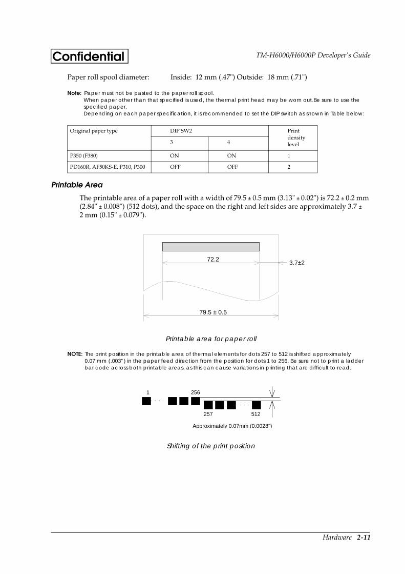
The printable area of a paper roll with a width of 79.5 ± 0.5 mm (3.13" ± 0.02") is 72.2 ± 0.2 mm (2.84" ± 0.008") (512 dots), and the space on the right and left sides are approximately 3.7 ± 2 mm (0.15" ± 0.079").
Printable area for paper roll
NOTE: The print position in the printable area of thermal elements for dots 257 to 512 is shifted approximately 0.07 mm (.003”) in the paper feed direction from the position for dots 1 to 256. Be sure not to print a ladder bar code across both printable areas, as this can cause variations in printing that are difficult to read.
Shifting of the print position
Paper roll spool diameter: Inside: 12 mm (.47") Outside: 18 mm (.71")
Original paper type DIP SW2 Print density level3 4
P350 (F380) ON ON 1
PD160R, AF50KS-E, P310, P300 OFF OFF 2
79.5 ± 0.5
3.7±272.2
Approximately 0.07mm (0.0028")
1 256
257 512
2-12 Hardware
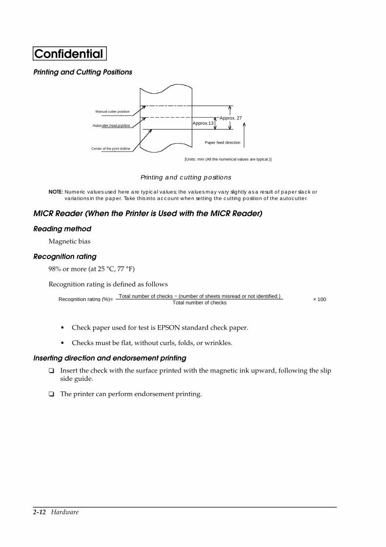
ConfidentialPrinting and Cutting Positions
Printing and cutting positions
NOTE: Numeric values used here are typical values; the values may vary slightly as a result of paper slack or variations in the paper. Take this into account when setting the cutting position of the autocutter.
MICR Reader (When the Printer is Used with the MICR Reader)
Reading method
Magnetic bias
Recognition rating
98% or more (at 25 °C, 77 °F)
Recognition rating is defined as follows
• Check paper used for test is EPSON standard check paper.
• Checks must be flat, without curls, folds, or wrinkles.
Inserting direction and endorsement printing
Insert the check with the surface printed with the magnetic ink upward, following the slip side guide.
The printer can perform endorsement printing.
Approx. 27Approx.13
Manual cutter position
Autocutter head position
Center of the print dotline
Paper feed direction
[Units: mm (All the numerical values are typical.)]
Total number of checks − (number of sheets misread or not identified.)Recognition rating (%)=
Total number of checks× 100
Hardware 2-13
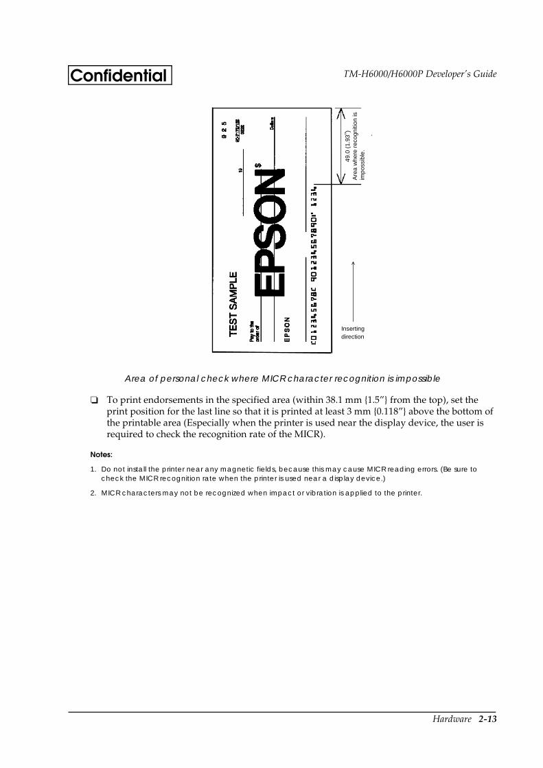
TM-H6000/H6000P Developer’s GuideConfidential
Area of personal check where MICR character recognition is impossible
To print endorsements in the specified area (within 38.1 mm 1.5” from the top), set the print position for the last line so that it is printed at least 3 mm 0.118” above the bottom of the printable area (Especially when the printer is used near the display device, the user is required to check the recognition rate of the MICR).
Notes:
1. Do not install the printer near any magnetic fields, because this may cause MICR reading errors. (Be sure to check the MICR recognition rate when the printer is used near a display device.)
2. MICR characters may not be recognized when impact or vibration is applied to the printer.
Insertingdirection
49.0
(1.
93” )
Are
a w
here
rec
ogni
tion
isim
poss
ible
.
2-14 Hardware
Confidential
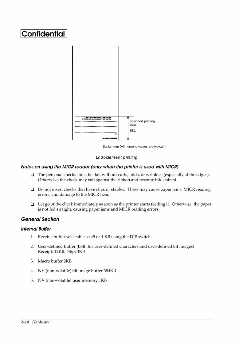
Endorsement printing
Notes on using the MICR reader (only when the printer is used with MICR)
The personal checks must be flat, without curls, folds, or wrinkles (especially at the edges). Otherwise, the check may rub against the ribbon and become ink-stained.
Do not insert checks that have clips or staples. These may cause paper jams, MICR reading errors, and damage to the MICR head.
Let go of the check immediately as soon as the printer starts feeding it. Otherwise, the paper is not fed straight, causing paper jams and MICR reading errors.
General Section
Internal Buffer
1. Receive buffer selectable as 45 or 4 KB using the DIP switch.
2. User-defined buffer (both for user-defined characters and user-defined bit images) Receipt: 12KB; Slip: 3KB
3. Macro buffer 2KB
4. NV (non-volatile) bit image buffer 384KB
5. NV (non-volatile) user memory 1KB
[Units: mm (All numeric values are typical.)]
Specified printingarea
38.1

Hardware 2-15
TM-H6000/H6000P Developer’s GuideConfidentialElectrical Characteristics
EMI and Safety Standards Applied (EMC is Tested Using the EPSON PS-170 Power Supply)
Reliability
Slip printer section:
Supply voltage: +24 VDC ± 10% (optional power supply: EPSON PS-170) Ripple voltage: 300 mVpp or less (only when the printer is used with the MICR reader)
Current consumption (at 24V except for drawer kickout driving)
Slip: Operating: Mean: Approximately 1.7A (Character font A α-N, all columns printing)Peak: Approximately 5.5A When the print platen is released: 2.0A (200 msec)
Receipt: Operating: Mean: Approximately 1.8A (Character font A α-N, all columns printing)Peak: Approximately 7.7A
Standby: Mean: Approximately 0.2A
Europe: CE Marking EN55022 EN50082-1 EN45501
Safety Standards: EN 60950 (TÜV)
North America: EMI: FCC/ICES-003 Class A Safety Standards: UL1950/CSA C22.2 No. 950
Japan: EMC: VCCI Class A JEIDA-52
Oceania: EMC: AS/NZS 3548 class B
Life (when printing alphanumeric characters)
Mechanism: 7,500,000 lines The printer is defined to have reached the end of its life when it reaches the beginning of the Wearout Period.
MICR reader mechanism (only when the printer is used with the MICR reader): 240,000 passes (when used with US personal checks)
MTBF 180,000 hours Failure is defined as a Random Failure occurring during the Random Failure Period.
2-16 Hardware
Confidential
Endorsement print mechanism section:
Receipt printer section:
Environmental Conditions
MCBF 18,000,000 lines This is an average failure interval based on failures relating to Wearout and Random Failures up to the life of 7.5 million lines.
Print head life: 200 million characters (when printed with font B only)
Life Mechanism: 1,350,000,000 lines The printer is defined to have reached the end of its life when it reaches the beginning of the Wearout Period.
Print head life: 6,750,000 characters
Life Mechanism: 15,000,000 lines The printer is defined to have reached the end of its life when it reaches the beginning of the Wearout Period.
MTBF 360,000 hours Failure is defined as a Random Failure occurring at the time of the Random Failure Period.
MCBF 52,000,000 lines This is an average failure interval based on failures relating to Wearout and Random Failures up to the life of 15 million lines.
Thermal head life: 100 million pulses, 100 Km
Autocutter life: 1,500,000 cuts
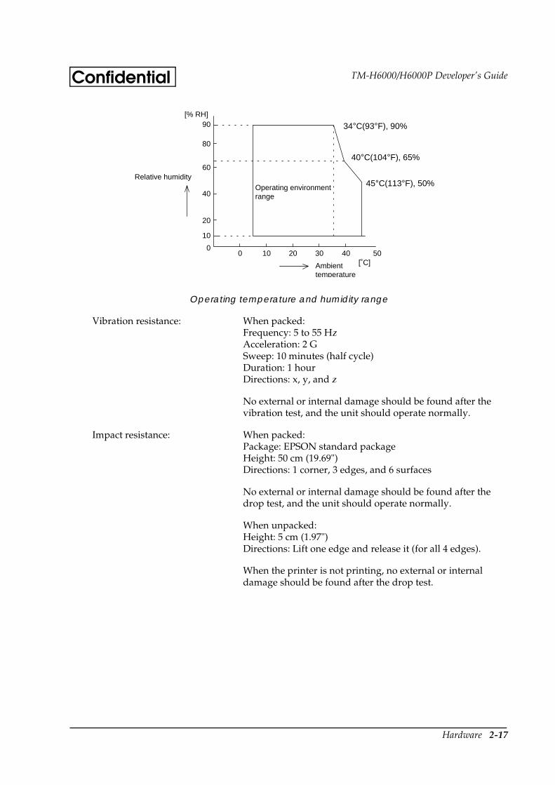
Temperature: Operating: 5 to 45 °C (41 to 113°F)Storage: –10 to 50 °C (14 to 122°F) (except for paper and ribbon)
Humidity: Operating: 10 to 90% RH Storage: 10 to 90% RH (except for paper and ribbon)
Hardware 2-17
TM-H6000/H6000P Developer’s GuideConfidential
Operating temperature and humidity range
Vibration resistance: When packed: Frequency: 5 to 55 Hz Acceleration: 2 G Sweep: 10 minutes (half cycle) Duration: 1 hour Directions: x, y, and z
No external or internal damage should be found after the vibration test, and the unit should operate normally.
Impact resistance: When packed: Package: EPSON standard package Height: 50 cm (19.69") Directions: 1 corner, 3 edges, and 6 surfaces
No external or internal damage should be found after the drop test, and the unit should operate normally.
When unpacked: Height: 5 cm (1.97") Directions: Lift one edge and release it (for all 4 edges).
When the printer is not printing, no external or internal damage should be found after the drop test.
Ambienttemperature
[˚C]
[% RH]
Relative humidityOperating environmentrange
34 ˚C, 90 %
40 ˚C, 65 %
45 ˚C, 50 %
90
80
60
20
40
10
0 0 10 20 30 40 50
34°C(93°F), 90%
40°C(104°F), 65%
45°C(113°F), 50%
2-18 Hardware
Confidential
Installation
The printer must be installed horizontally.
Configuration
Interfaces
RS-232 Serial Interface
Specifications
The data word length, baud rate, and parity depend on the DIP switch settings. (See “DIP Switches” in Chapter 1.) The stop bit for the printer side is fixed to 1.
Switching between online and offline
The printer does not have an online/offline switch. The printer goes offline:
1. Between when the power is turned on (including reset using the interface) and when the printer is ready to receive data.
2. During the self-test.
3. When the cover is open (the cover for the paper source selected by ESC c 0).
4. During paper feeding using the paper FEED switch.
5. When the printer stops printing due to a paper-end (only when the paper roll is not present).
6. When an error has occurred.
Acoustic noise (operating): Receipt:
When using autocutter:Approximately 52 dB (bystander position)
When not using autocutter:Approximately 45 dB (bystander position)
Data transmission: Serial
Synchronization: Asynchronous
Handshaking: DTR/DSR or XON/XOFF control
Signal levels: MARK = -3 to -15 V: Logic “1”SPACE = +3 to +15 V: Logic “0”
Stop bits: 1 bit (fixed)
Connector (printer side): Female DSUB-25 pin connector
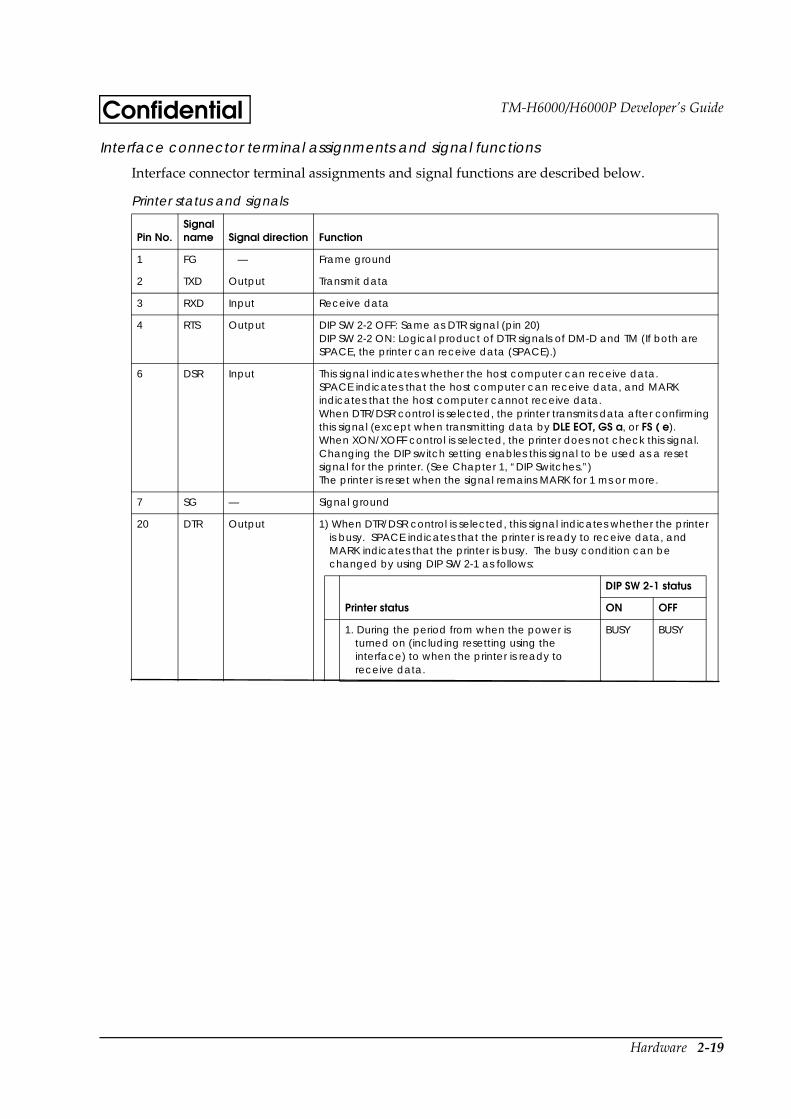
Hardware 2-19
TM-H6000/H6000P Developer’s GuideConfidentialInterface connector terminal assignments and signal functions
Interface connector terminal assignments and signal functions are described below.
Printer status and signals
Pin No.Signal name Signal direction Function
1 FG — Frame ground
2 TXD Output Transmit data
3 RXD Input Receive data
4 RTS Output DIP SW 2-2 OFF: Same as DTR signal (pin 20)DIP SW 2-2 ON: Logical product of DTR signals of DM-D and TM (If both are SPACE, the printer can receive data (SPACE).)
6 DSR Input This signal indicates whether the host computer can receive data.SPACE indicates that the host computer can receive data, and MARK indicates that the host computer cannot receive data.When DTR/DSR control is selected, the printer transmits data after confirming this signal (except when transmitting data by DLE EOT, GS a, or FS ( e).When XON/XOFF control is selected, the printer does not check this signal.Changing the DIP switch setting enables this signal to be used as a reset signal for the printer. (See Chapter 1, “DIP Switches.”)The printer is reset when the signal remains MARK for 1 ms or more.
7 SG — Signal ground
20 DTR Output 1) When DTR/DSR control is selected, this signal indicates whether the printer is busy. SPACE indicates that the printer is ready to receive data, and MARK indicates that the printer is busy. The busy condition can be changed by using DIP SW 2-1 as follows:
DIP SW 2-1 status
Printer status ON OFF
1. During the period from when the power is turned on (including resetting using the interface) to when the printer is ready to receive data.
BUSY BUSY
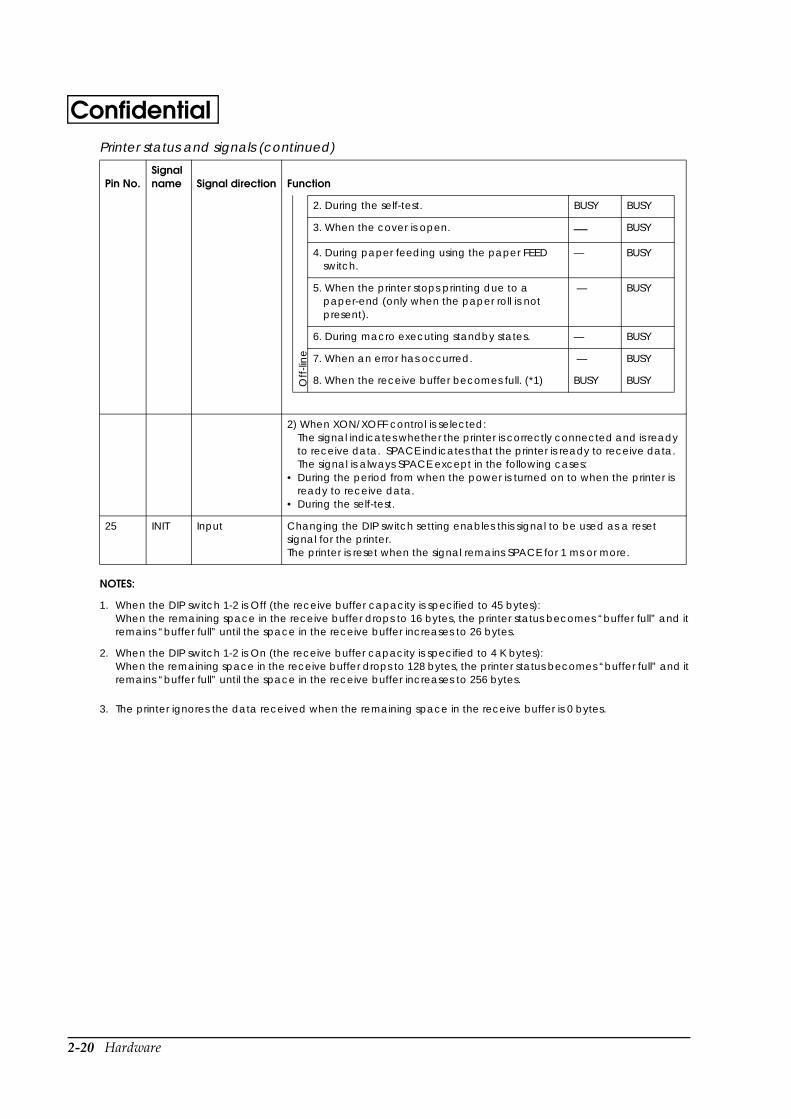
2-20 Hardware
Confidential
NOTES:
1. When the DIP switch 1-2 is Off (the receive buffer capacity is specified to 45 bytes):When the remaining space in the receive buffer drops to 16 bytes, the printer status becomes “buffer full” and it remains “buffer full” until the space in the receive buffer increases to 26 bytes.
2. When the DIP switch 1-2 is On (the receive buffer capacity is specified to 4 K bytes): When the remaining space in the receive buffer drops to 128 bytes, the printer status becomes “buffer full” and it remains “buffer full” until the space in the receive buffer increases to 256 bytes.
3. The printer ignores the data received when the remaining space in the receive buffer is 0 bytes.
Off
-lin
e
2. During the self-test. BUSY BUSY
3. When the cover is open. — BUSY
4. During paper feeding using the paper FEED switch.
— BUSY
5. When the printer stops printing due to a paper-end (only when the paper roll is not present).
— BUSY
6. During macro executing standby states. — BUSY
7. When an error has occurred. — BUSY
8. When the receive buffer becomes full. (*1) BUSY BUSY
2) When XON/XOFF control is selected:The signal indicates whether the printer is correctly connected and is ready to receive data. SPACE indicates that the printer is ready to receive data. The signal is always SPACE except in the following cases:
• During the period from when the power is turned on to when the printer is ready to receive data.
• During the self-test.
25 INIT Input Changing the DIP switch setting enables this signal to be used as a reset signal for the printer.The printer is reset when the signal remains SPACE for 1 ms or more.
Printer status and signals (continued)
Pin No.Signal name Signal direction Function

Hardware 2-21
TM-H6000/H6000P Developer’s GuideConfidentialXON/XOFF transmission timing
When XON/XOFF control is selected, the printer transmits XON or XOFF signals as follows. Transmission timing differs depending on the DIP SW1-3 setting.
NOTES:
• The XON code is <11>H and the XOFF code is <13>H.
• In case 3, XON is not transmitted when the receive buffer is full.
• In case 6, XOFF is not transmitted when the receive buffer is full.
• When the DIP SW 2-1 is set to OFF, XON is not transmitted if the printer is in offline state in case 2.
Notes on setting DIP switch 2-1 to ON
1. The printer mechanism stops but does not become busy when: an error has occurred, the cover is open, printing stops due to a paper-end, or paper is fed using the paper FEED button.
2. When setting DIP switch 2-1 to ON to enable handshaking with the printer, be sure to check the printer status using the GS a command and the ASB function. In this setting, the default value of n for GS a is 2. The printer automatically transmits the printer status, depending on online/offline changes.
3. When using DLE EOT, DLE ENQ, and DLE DC4 be sure that the receive buffer does not become full.
• When using a host that cannot transmit data when the printer is busy:If an error has occurred, DLE EOT, DLE ENQ, and DLE DC4 cannot be used when the printer is busy due to a receive buffer-full state.
• When using a host that can transmit data when the printer is busy:When the receive buffer becomes full while transmitting bit-image data, DLE EOT or DLE ENQ, and DLE DC4 used while sending the bit-image data is processed as bit-image data. The data transmitted when the receive buffer is full may be lost.
• Example: Check the printer status using GS I or GS r after transmitting each line of data and use the 4KB receive buffer. Transmit one line of data so that the receive buffer does not become full.
XON/XOFF transmission timing
Printer status
DIP SW 2-1 status
ON OFF
XON transmission 1. When the printer goes online after turning on the power (or reset using interface)
Transmit Transmit
2. When the receive buffer is released from the buffer full state Transmit Transmit
3. When the printer switches from offline to online — Transmit
4. When the printer recovers from an error using the DLE ENQ 1 or DLE ENQ 2 commands
— Transmit
XOFF transmission 5. When the receive buffer becomes full Transmit Transmit
6. When the printer switches from online to offline — Transmit
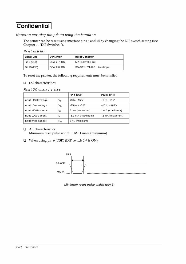
2-22 Hardware
ConfidentialNotes on resetting the printer using the interface
The printer can be reset using interface pins 6 and 25 by changing the DIP switch setting (see Chapter 1, “DIP Switches”).
To reset the printer, the following requirements must be satisfied.
DC characteristics:
AC characteristics:Minimum reset pulse width: TRS 1 msec (minimum)
When using pin 6 (DSR) (DIP switch 2-7 is ON):
Minimum reset pulse width (pin 6)
Reset switching
Signal Line DIP Switch Reset Condition
Pin 6 (DSR) DSW 2-7: ON MARK level input
Pin 25 (INIT) DSW 2-8: ON SPACE or TTL-HIGH level input
Reset DC characteristics
Pin 6 (DSR) Pin 25 (INIT)
Input HIGH voltage VIH +3 to +15 V +2 to +15 V
Input LOW voltage VIL –15 to + –3 V –15 to + 0.8 V
Input HIGH current: IIH 5 mA (maximum) 1 mA (maximum)
Input LOW current: IIL –5.3 mA (maximum) –2 mA (maximum)
Input impedance: RIN 3 KΩ (minimum)
TRS
H
L
SPACE
MARK
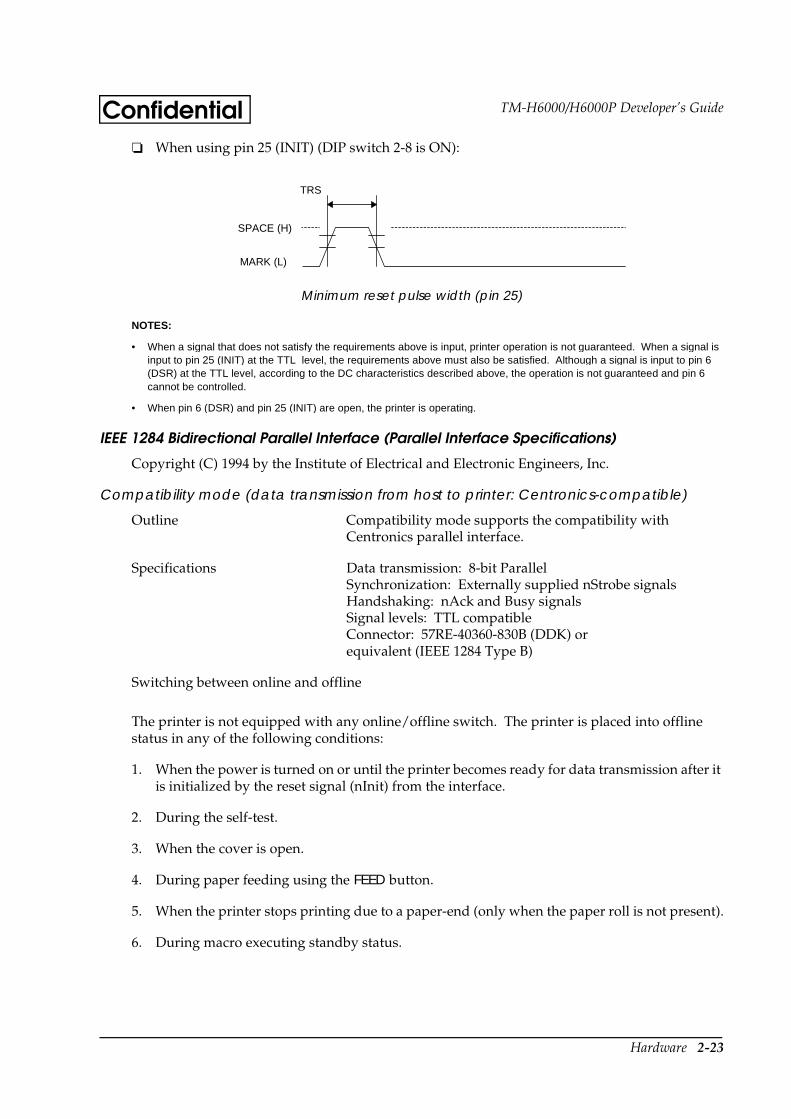
Hardware 2-23
TM-H6000/H6000P Developer’s GuideConfidential When using pin 25 (INIT) (DIP switch 2-8 is ON):
Minimum reset pulse width (pin 25)
NOTES:
• When a signal that does not satisfy the requirements above is input, printer operation is not guaranteed. When a signal is input to pin 25 (INIT) at the TTL level, the requirements above must also be satisfied. Although a signal is input to pin 6 (DSR) at the TTL level, according to the DC characteristics described above, the operation is not guaranteed and pin 6 cannot be controlled.
• When pin 6 (DSR) and pin 25 (INIT) are open, the printer is operating.
IEEE 1284 Bidirectional Parallel Interface (Parallel Interface Specifications)
Copyright (C) 1994 by the Institute of Electrical and Electronic Engineers, Inc.
Compatibility mode (data transmission from host to printer: Centronics-compatible)
The printer is not equipped with any online/offline switch. The printer is placed into offline status in any of the following conditions:
1. When the power is turned on or until the printer becomes ready for data transmission after it is initialized by the reset signal (nInit) from the interface.
2. During the self-test.
3. When the cover is open.
4. During paper feeding using the FEED button.
5. When the printer stops printing due to a paper-end (only when the paper roll is not present).
6. During macro executing standby status.
Outline Compatibility mode supports the compatibility with Centronics parallel interface.
Specifications Data transmission: 8-bit ParallelSynchronization: Externally supplied nStrobe signalsHandshaking: nAck and Busy signalsSignal levels: TTL compatibleConnector: 57RE-40360-830B (DDK) or equivalent (IEEE 1284 Type B)
Switching between online and offline
TRS
H
L
SPACE (H)
MARK (L)
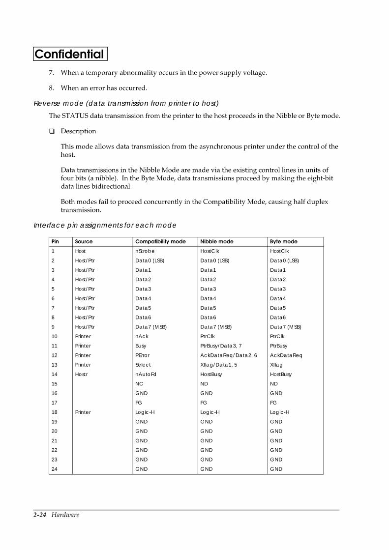
2-24 Hardware
Confidential7. When a temporary abnormality occurs in the power supply voltage.
8. When an error has occurred.
Reverse mode (data transmission from printer to host)
The STATUS data transmission from the printer to the host proceeds in the Nibble or Byte mode.
Description
This mode allows data transmission from the asynchronous printer under the control of the host.
Data transmissions in the Nibble Mode are made via the existing control lines in units of four bits (a nibble). In the Byte Mode, data transmissions proceed by making the eight-bit data lines bidirectional.
Both modes fail to proceed concurrently in the Compatibility Mode, causing half duplex transmission.
Interface pin assignments for each mode
Pin Source Compatibility mode Nibble mode Byte mode
1 Host nStrobe HostClk HostClk
2 Host/Ptr Data0 (LSB) Data0 (LSB) Data0 (LSB)
3 Host/Ptr Data1 Data1 Data1
4 Host/Ptr Data2 Data2 Data2
5 Host/Ptr Data3 Data3 Data3
6 Host/Ptr Data4 Data4 Data4
7 Host/Ptr Data5 Data5 Data5
8 Host/Ptr Data6 Data6 Data6
9 Host/Ptr Data7 (MSB) Data7 (MSB) Data7 (MSB)
10 Printer nAck PtrClk PtrClk
11 Printer Busy PtrBusy/Data3, 7 PtrBusy
12 Printer PError AckDataReq/Data2, 6 AckDataReq
13 Printer Select Xflag/Data1, 5 Xflag
14 Hostr nAutoFd HostBusy HostBusy
15 NC ND ND
16 GND GND GND
17 FG FG FG
18 Printer Logic-H Logic-H Logic-H
19 GND GND GND
20 GND GND GND
21 GND GND GND
22 GND GND GND
23 GND GND GND
24 GND GND GND
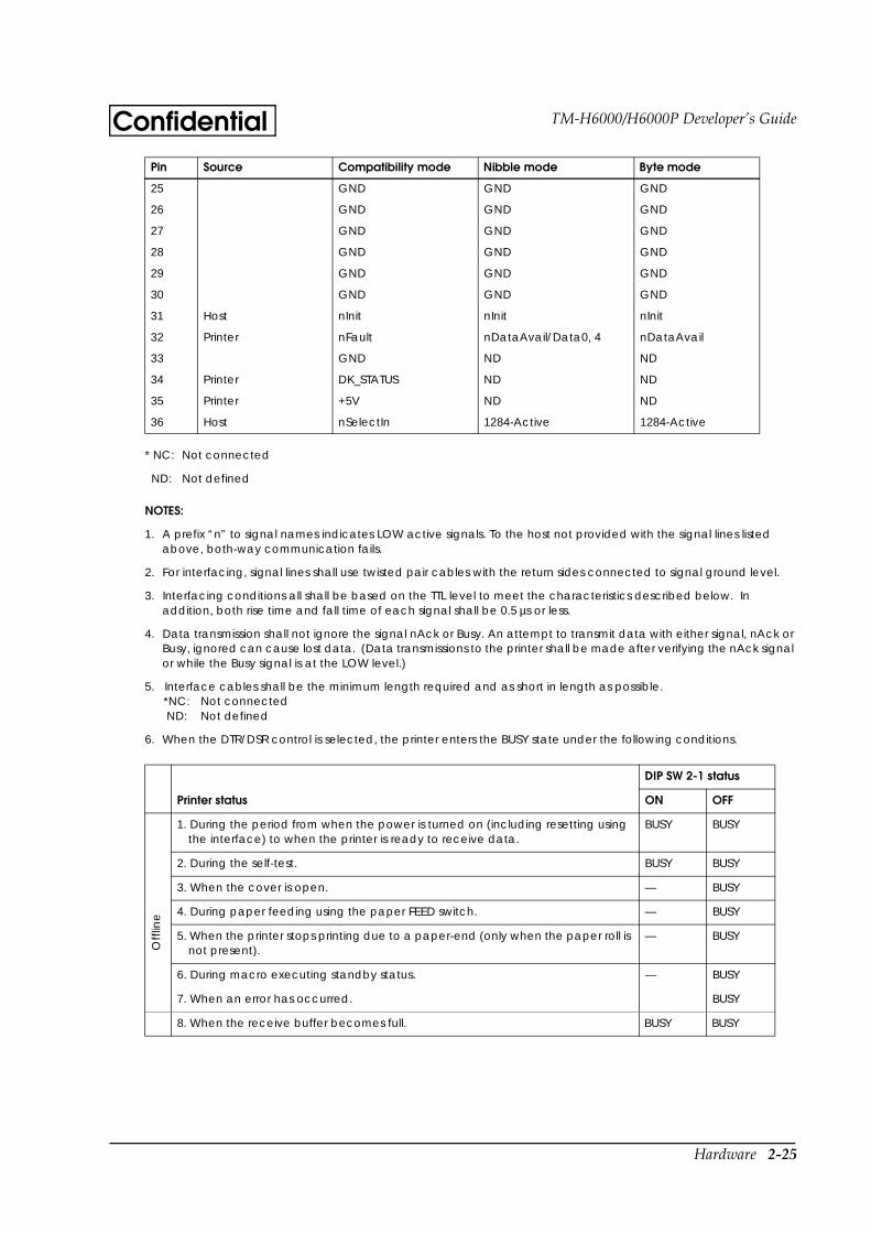
Hardware 2-25
TM-H6000/H6000P Developer’s GuideConfidential
* NC: Not connected
ND: Not defined
NOTES:
1. A prefix “n” to signal names indicates LOW active signals. To the host not provided with the signal lines listed above, both-way communication fails.
2. For interfacing, signal lines shall use twisted pair cables with the return sides connected to signal ground level.
3. Interfacing conditions all shall be based on the TTL level to meet the characteristics described below. In addition, both rise time and fall time of each signal shall be 0.5 µs or less.
4. Data transmission shall not ignore the signal nAck or Busy. An attempt to transmit data with either signal, nAck or Busy, ignored can cause lost data. (Data transmissions to the printer shall be made after verifying the nAck signal or while the Busy signal is at the LOW level.)
5. Interface cables shall be the minimum length required and as short in length as possible.*NC: Not connected ND: Not defined
6. When the DTR/DSR control is selected, the printer enters the BUSY state under the following conditions.
25 GND GND GND
26 GND GND GND
27 GND GND GND
28 GND GND GND
29 GND GND GND
30 GND GND GND
31 Host nInit nInit nInit
32 Printer nFault nDataAvail/Data0, 4 nDataAvail
33 GND ND ND
34 Printer DK_STATUS ND ND
35 Printer +5V ND ND
36 Host nSelectIn 1284-Active 1284-Active
DIP SW 2-1 status
Printer status ON OFF
1. During the period from when the power is turned on (including resetting using the interface) to when the printer is ready to receive data.
BUSY BUSY
Off
line
2. During the self-test. BUSY BUSY
3. When the cover is open. — BUSY
4. During paper feeding using the paper FEED switch. — BUSY
5. When the printer stops printing due to a paper-end (only when the paper roll is not present).
— BUSY
6. During macro executing standby status. — BUSY
7. When an error has occurred. BUSY
8. When the receive buffer becomes full. BUSY BUSY
Pin Source Compatibility mode Nibble mode Byte mode
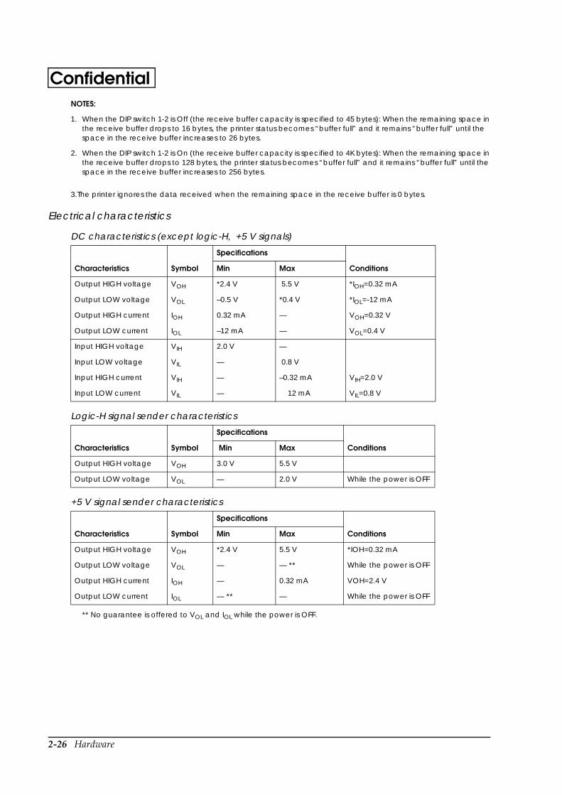
2-26 Hardware
ConfidentialNOTES:
1. When the DIP switch 1-2 is Off (the receive buffer capacity is specified to 45 bytes): When the remaining space in the receive buffer drops to 16 bytes, the printer status becomes “buffer full” and it remains “buffer full” until the space in the receive buffer increases to 26 bytes.
2. When the DIP switch 1-2 is On (the receive buffer capacity is specified to 4K bytes): When the remaining space in the receive buffer drops to 128 bytes, the printer status becomes “buffer full” and it remains “buffer full” until the space in the receive buffer increases to 256 bytes.
3.The printer ignores the data received when the remaining space in the receive buffer is 0 bytes.
Electrical characteristics
** No guarantee is offered to VOL and IOL while the power is OFF.
DC characteristics (except logic-H, +5 V signals)
Characteristics Symbol
Specifications
ConditionsMin Max
Output HIGH voltage VOH *2.4 V 5.5 V *IOH=0.32 mA
Output LOW voltage VOL –0.5 V *0.4 V *IOL=-12 mA
Output HIGH current IOH 0.32 mA — VOH=0.32 V
Output LOW current IOL –12 mA — VOL=0.4 V
Input HIGH voltage VIH 2.0 V —
Input LOW voltage VIL — 0.8 V
Input HIGH current VIH — –0.32 mA VIH=2.0 V
Input LOW current VIL — 12 mA VIL=0.8 V
Logic-H signal sender characteristics
Characteristics Symbol
Specifications
Conditions Min Max
Output HIGH voltage VOH 3.0 V 5.5 V
Output LOW voltage VOL — 2.0 V While the power is OFF
+5 V signal sender characteristics
Characteristics Symbol
Specifications
ConditionsMin Max
Output HIGH voltage VOH *2.4 V 5.5 V *IOH=0.32 mA
Output LOW voltage VOL — — ** While the power is OFF
Output HIGH current IOH — 0.32 mA VOH=2.4 V
Output LOW current IOL — ** — While the power is OFF
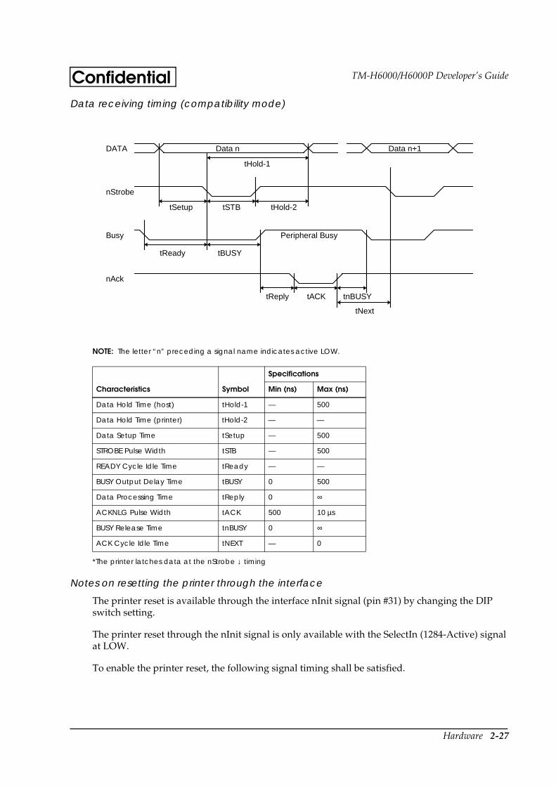
Hardware 2-27
TM-H6000/H6000P Developer’s GuideConfidentialData receiving timing (compatibility mode)
NOTE: The letter “n” preceding a signal name indicates active LOW.
*The printer latches data at the nStrobe ↓ timing
Notes on resetting the printer through the interface
The printer reset is available through the interface nInit signal (pin #31) by changing the DIP switch setting.
The printer reset through the nInit signal is only available with the SelectIn (1284-Active) signal at LOW.
To enable the printer reset, the following signal timing shall be satisfied.
Characteristics Symbol
Specifications
Min (ns) Max (ns)
Data Hold Time (host) tHold-1 — 500
Data Hold Time (printer) tHold-2 — —
Data Setup Time tSetup — 500
STROBE Pulse Width tSTB — 500
READY Cycle Idle Time tReady — —
BUSY Output Delay Time tBUSY 0 500
Data Processing Time tReply 0 ∞
ACKNLG Pulse Width tACK 500 10 µs
BUSY Release Time tnBUSY 0 ∞
ACK Cycle Idle Time tNEXT — 0
DATA Data n Data n+1
nStrobe
Busy Peripheral Busy
nAck
tHold-1
tHold-2tSTBtSetup
tBUSYtReady
tNext
tnBUSYtACKtReply
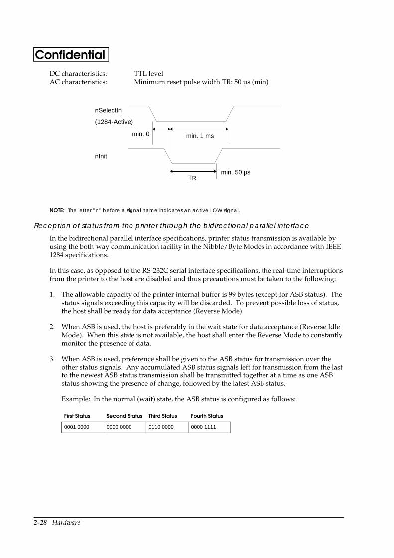
2-28 Hardware
ConfidentialDC characteristics: TTL levelAC characteristics: Minimum reset pulse width TR: 50 µs (min)
NOTE: The letter ”n” before a signal name indicates an active LOW signal.
Reception of status from the printer through the bidirectional parallel interface
In the bidirectional parallel interface specifications, printer status transmission is available by using the both-way communication facility in the Nibble/Byte Modes in accordance with IEEE 1284 specifications.
In this case, as opposed to the RS-232C serial interface specifications, the real-time interruptions from the printer to the host are disabled and thus precautions must be taken to the following:
1. The allowable capacity of the printer internal buffer is 99 bytes (except for ASB status). The status signals exceeding this capacity will be discarded. To prevent possible loss of status, the host shall be ready for data acceptance (Reverse Mode).
2. When ASB is used, the host is preferably in the wait state for data acceptance (Reverse Idle Mode). When this state is not available, the host shall enter the Reverse Mode to constantly monitor the presence of data.
3. When ASB is used, preference shall be given to the ASB status for transmission over the other status signals. Any accumulated ASB status signals left for transmission from the last to the newest ASB status transmission shall be transmitted together at a time as one ASB status showing the presence of change, followed by the latest ASB status.
Example: In the normal (wait) state, the ASB status is configured as follows:
First Status Second Status Third Status Fourth Status
0001 0000 0000 0000 0110 0000 0000 1111
nSelectIn
(1284-Active)
nInit
min. 0 min. 1 ms
min. 50 µsTR
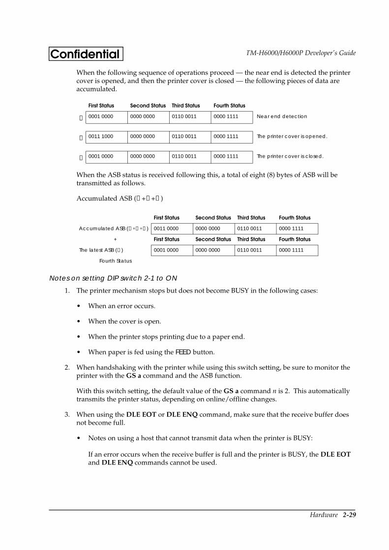
Hardware 2-29
TM-H6000/H6000P Developer’s GuideConfidentialWhen the following sequence of operations proceed — the near end is detected the printer cover is opened, and then the printer cover is closed — the following pieces of data are accumulated.
When the ASB status is received following this, a total of eight (8) bytes of ASB will be transmitted as follows.
Accumulated ASB (①+②+③)
Notes on setting DIP switch 2-1 to ON
1. The printer mechanism stops but does not become BUSY in the following cases:
• When an error occurs.
• When the cover is open.
• When the printer stops printing due to a paper end.
• When paper is fed using the FEED button.
2. When handshaking with the printer while using this switch setting, be sure to monitor the printer with the GS a command and the ASB function.
With this switch setting, the default value of the GS a command n is 2. This automatically transmits the printer status, depending on online/offline changes.
3. When using the DLE EOT or DLE ENQ command, make sure that the receive buffer does not become full.
• Notes on using a host that cannot transmit data when the printer is BUSY:
If an error occurs when the receive buffer is full and the printer is BUSY, the DLE EOT and DLE ENQ commands cannot be used.
First Status Second Status Third Status Fourth Status
① 0001 0000 0000 0000 0110 0011 0000 1111 Near end detection
② 0011 1000 0000 0000 0110 0011 0000 1111 The printer cover is opened.
③ 0001 0000 0000 0000 0110 0011 0000 1111 The printer cover is closed.
First Status Second Status Third Status Fourth Status
Accumulated ASB (①+②+③) 0011 0000 0000 0000 0110 0011 0000 1111
+ First Status Second Status Third Status Fourth Status
The latest ASB (③) 0001 0000 0000 0000 0110 0011 0000 1111
Fourth Status

2-30 Hardware
Confidential• Notes on using a host that can transmit data when the printer is BUSY:
If a DLE EOT, DLE ENQ, or DLE DC 4 command is used while sending bit-image data, and the receive buffer-full state is encountered during transmission of the data, the DLE EOT, DLE ENQ or DLE DC 4 is processed as bit-image data.
In addition, the data transmitted during the receive buffer-full state may be lost.
Example of use: Set the receive buffer to 4KB, and check the status using GS l or GS r after each line of printing is transmitted. Transmit one line of data at a time so that the receive buffer does not become full.
RS-485 Serial Interface
(RS-485 serial interface specification is a dealer option.)
Specifications (RS-485-compatible)
NOTE:
The handshaking data, word length, baud rate, and parity depend on the DIP switches (see Chapter 1). Data transmitted from the printer has 1 stop bit (fixed).
DR1 > DR2 CS1 > CS2 indicates that:
Channel 1 is high.Channel 2 is low.
DR1 < DR2 CS1 < CS2 indicates that:
Data transmission: Serial
Synchronization: Asynchronous
Handshaking: Depends on the DIP switch settings (DTR/DSR or XON/XOFF control)
Signal levels: 2.0 V to 5.0 V: Logic “1” 0.0 V to 0.8 V: Logic “0”
Baud rates: 2400, 4800, 9600, 19200 bps
Data word lengths: 7 or 8 bits
Parity settings: None, even, odd
Stop bits: 1 bit (fixed)
Connector (printer side): Female D-SUB-25 pin connector
Hardware 2-31
TM-H6000/H6000P Developer’s GuideConfidentialChannel 2 is high.Channel 1 is low.
If the electric potential of CS1 is higher than that of CS2, the printer is ready for communication (the host is ready to receive data). If the electric potential of CS1 is lower than that of CS2, the printer is not ready for communication (the host is not ready to receive data).
If the electric potential of DR1 is higher than that of DR2, the printer is ready for communication (the host is ready to receive data). If the electric potential of DR1 is lower than that of DR2, the printer is not ready for communication (the host is not ready to receive data).
Switching between online and offline
The printer does not have an online/offline switch.
The printer goes offline:
1. Between when the power is turned on (including reset using the interface) and when the printer is ready to receive data.
2. During the self-test.
3. When the cover is open.
4. During paper feeding using the FEED button.
5. When the printer stops printing due to paper-end (in cases when an empty paper supply is detected by either paper roll end detector or the paper roll near-end detector with a printing halt feature set to enabled by ESC c 4).
6. During macro executing standby status.
7. When a temporary abnormality occurs in the power supply voltage.
8. When an error has occurred.
9. When the receive buffer becomes full. (*1)
Signal levels and communication control functions
CS1 CS2 Function
H L Communication is available
L H Communication is not available
Signal levels and communication control functions
DR1 DR2 Function
H L Communication is available
L H Communication is not available
2-32 Hardware
Confidential*1: • When the DIP switch 1-2 is Off (the receive buffer capacity is specified to 45 bytes): When the remaining space in the
receive buffer drops to 16 bytes, the printer status becomes “buffer full,” and it remains “buffer full” until the space in the receive buffer increases to 26 bytes.
• When the DIP switch 1-2 is On (the receive buffer capacity is specified to 4 K bytes): When the remaining space in the receive buffer drops to 128 bytes, the printer status becomes “buffer full,” and it remains “buffer full” until the space in the receive buffer increases to 256 bytes.
• The printer ignores the data received when the remaining space in the receive buffer is 0 bytes.
See “RS-232 Serial Interface” for notes on setting DIP switch 2-1 to ON.
Interface pin assignments
Printer status and signals
Pin number
Signal name
Signal direction Function
1 FG — Frame ground
2 SD1 Output Transmit data
3 SD2 Output Transmit data
4 RD1 Input Receive data
5 RD2 Input Receive data
7 SG — Signal ground
8 DR1 Output When DTR/DRS is selected, this signal indicates whether the host computer is BUSY or READY.
9 DR2 Output 1) DR1>DR2 indicates that the printer is READY and DR1<DR2 indicates that the printer is BUSY. The BUSY condition can be changed, depending on the offline conditions set by the DIP switches.When the DTR/DSR control is selected, the printer enters the BUSY state (DR1<DR2) under the following conditions.
DIP SW 2-1 status
Printer status ON OFF
1. During the period from when the power is turned on (including resetting using the interface) to when the printer is ready to receive data.
BUSY BUSY
2. During the self-test. BUSY BUSY
3. When the cover is open. — BUSY
4. During paper feeding using the paper FEED switch.
— BUSY
5. When the printer stops printing due to a paper-end (only when the paper roll is not present).
— BUSY
6. During macro executing standby status. — BUSY
7. When an error has occurred. BUSY
8. When the receive buffer becomes full. (*1) BUSY BUSY
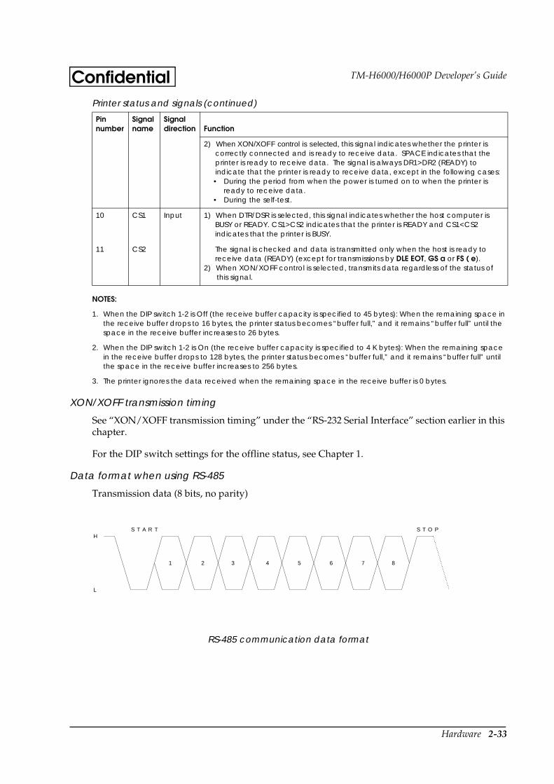
Hardware 2-33
TM-H6000/H6000P Developer’s GuideConfidential
NOTES:
1. When the DIP switch 1-2 is Off (the receive buffer capacity is specified to 45 bytes): When the remaining space in the receive buffer drops to 16 bytes, the printer status becomes “buffer full,” and it remains “buffer full” until the space in the receive buffer increases to 26 bytes.
2. When the DIP switch 1-2 is On (the receive buffer capacity is specified to 4 K bytes): When the remaining space in the receive buffer drops to 128 bytes, the printer status becomes “buffer full,” and it remains “buffer full” until the space in the receive buffer increases to 256 bytes.
3. The printer ignores the data received when the remaining space in the receive buffer is 0 bytes.
XON/XOFF transmission timing
See “XON/XOFF transmission timing” under the “RS-232 Serial Interface” section earlier in this chapter.
For the DIP switch settings for the offline status, see Chapter 1.
Data format when using RS-485
Transmission data (8 bits, no parity)
RS-485 communication data format
2) When XON/XOFF control is selected, this signal indicates whether the printer is correctly connected and is ready to receive data. SPACE indicates that the printer is ready to receive data. The signal is always DR1>DR2 (READY) to indicate that the printer is ready to receive data, except in the following cases:• During the period from when the power is turned on to when the printer is
ready to receive data.• During the self-test.
10 CS1 Input 1) When DTR/DSR is selected, this signal indicates whether the host computer is BUSY or READY. CS1>CS2 indicates that the printer is READY and CS1<CS2 indicates that the printer is BUSY.
11 CS2 The signal is checked and data is transmitted only when the host is ready to receive data (READY) (except for transmissions by DLE EOT, GS a or FS ( e).
2) When XON/XOFF control is selected, transmits data regardless of the status of this signal.
Printer status and signals (continued)
Pin number
Signal name
Signal direction Function
S T A R T S T O PH
1 2 3 4 5 6 7 8
L
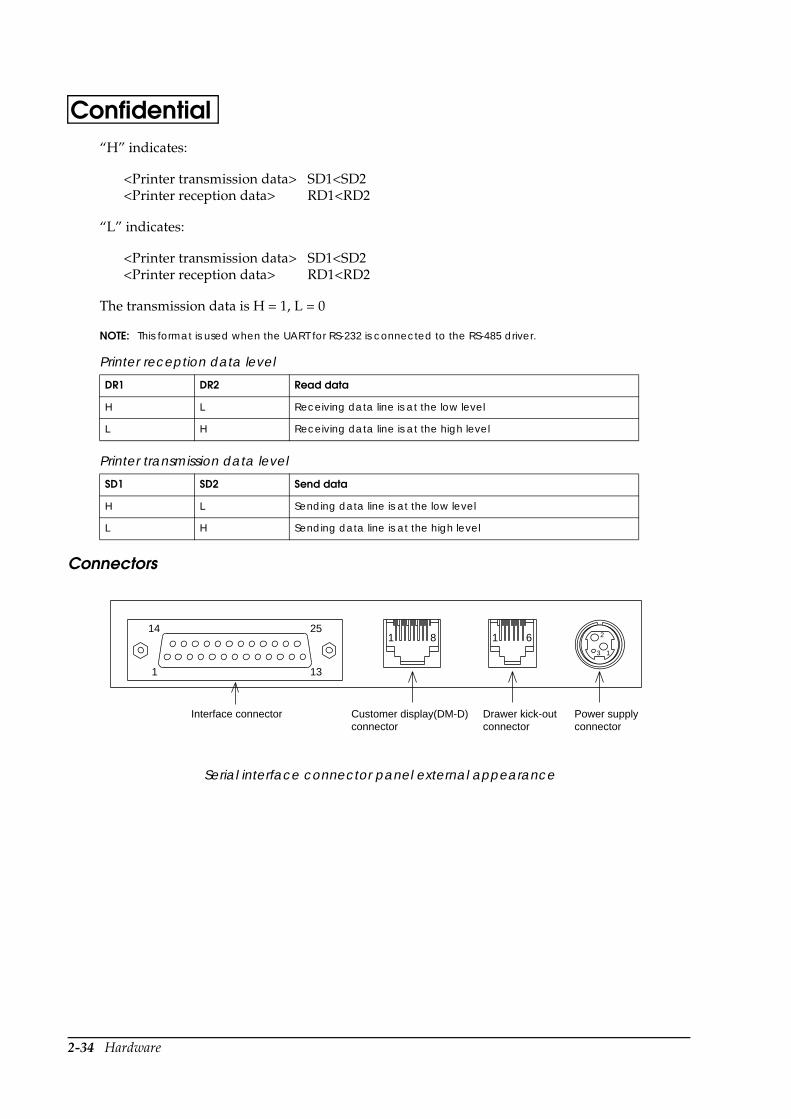
2-34 Hardware
Confidential“H” indicates:
<Printer transmission data> SD1<SD2<Printer reception data> RD1<RD2
“L” indicates:
<Printer transmission data> SD1<SD2<Printer reception data> RD1<RD2
The transmission data is H = 1, L = 0
NOTE: This format is used when the UART for RS-232 is connected to the RS-485 driver.
Connectors
Serial interface connector panel external appearance
Printer reception data level
DR1 DR2 Read data
H L Receiving data line is at the low level
L H Receiving data line is at the high level
Printer transmission data level
SD1 SD2 Send data
H L Sending data line is at the low level
L H Sending data line is at the high level
Interface connector Customer display(DM-D)connector
Drawer kick-outconnector
Power supplyconnector
14 25
1 13
1 8 1 6 2
3 1
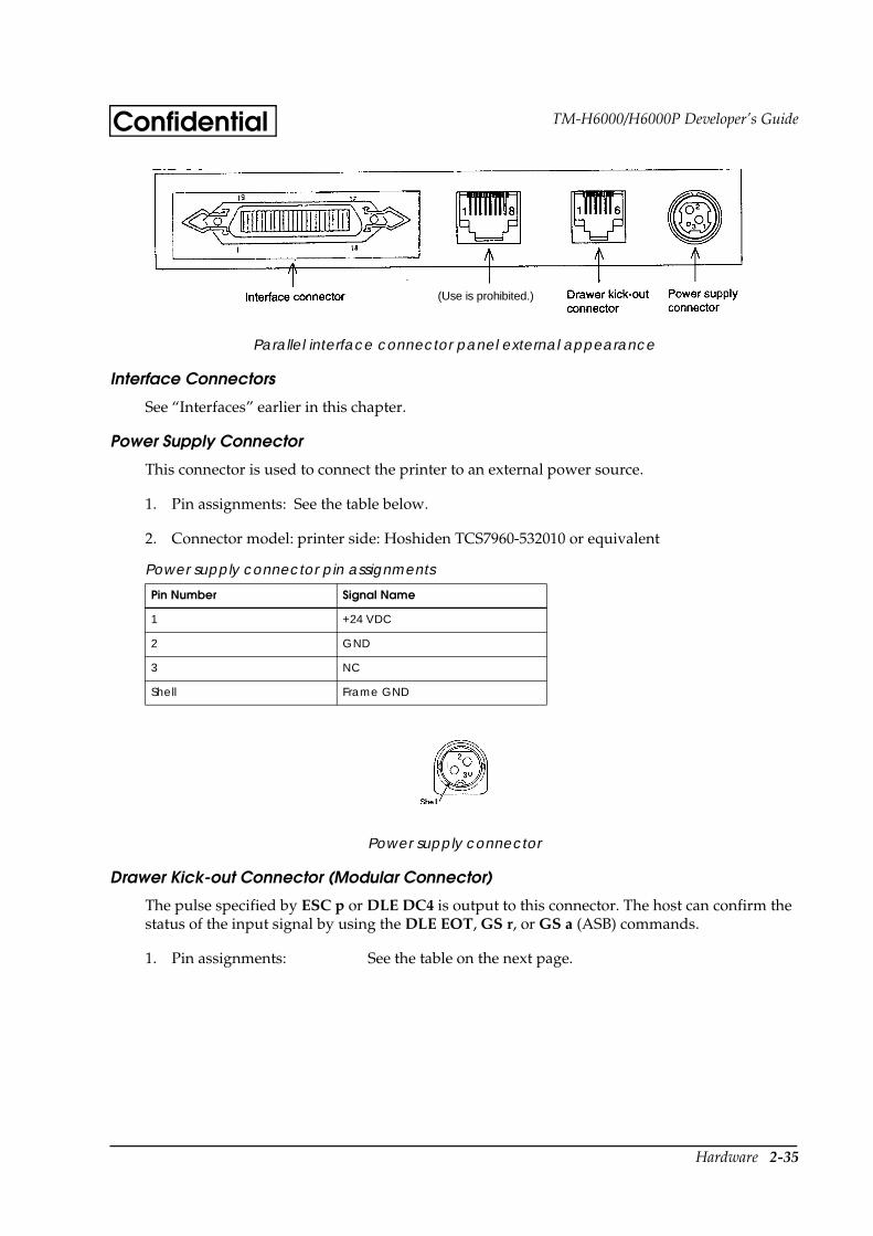
Hardware 2-35
TM-H6000/H6000P Developer’s GuideConfidential
Parallel interface connector panel external appearance
Interface Connectors
See “Interfaces” earlier in this chapter.
Power Supply Connector
This connector is used to connect the printer to an external power source.
1. Pin assignments: See the table below.
2. Connector model: printer side: Hoshiden TCS7960-532010 or equivalent
Power supply connector
Drawer Kick-out Connector (Modular Connector)
The pulse specified by ESC p or DLE DC4 is output to this connector. The host can confirm the status of the input signal by using the DLE EOT, GS r, or GS a (ASB) commands.
1. Pin assignments: See the table on the next page.
Power supply connector pin assignments
Pin Number Signal Name
1 +24 VDC
2 GND
3 NC
Shell Frame GND
(Use is prohibited.)
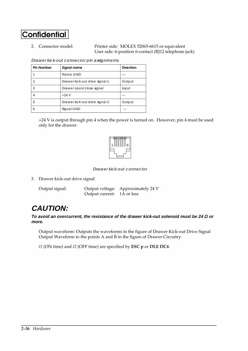
2-36 Hardware
Confidential2. Connector model: Printer side: MOLEX 52065-6615 or equivalent
User side: 6-position 6-contact (RJ12 telephone jack)
+24 V is output through pin 4 when the power is turned on. However, pin 4 must be used only for the drawer.
Drawer kick-out connector
3. Drawer kick-out drive signal
Output signal: Output voltage: Approximately 24 VOutput current: 1A or less
CAUTION:To avoid an overcurrent, the resistance of the drawer kick-out solenoid must be 24 ΩΩ or more.
Output waveform: Outputs the waveforms in the figure of Drawer Kick-out Drive Signal Output Waveform to the points A and B in the figure of Drawer Circuitry.
t1 (ON time) and t2 (OFF time) are specified by ESC p or DLE DC4.
Drawer kick-out connector pin assignments
Pin Number Signal name Direction
1 Frame GND —
2 Drawer kick-out drive signal 1 Output
3 Drawer open/close signal Input
4 +24 V —
5 Drawer kick-out drive signal 2 Output
6 Signal GND —
1 6

Hardware 2-37
TM-H6000/H6000P Developer’s GuideConfidential
Drawer kick-out drive signal output waveform
4. Drawer open/close signal
Input signal level (connector pin 3): “L” = 0 to 0.8 V“H” = 2 to 5 V
Drawer circuitry
NOTES:
1. Two driver transistors cannot be energized simultaneously.
2. The driver must not be energized continuously.
3. Be sure to use the printer power supply (connector pin 4) for the drawer power source.
4. The resistance of the drawer kick-out solenoid must not be less than the specified resistance. Otherwise, an overcurrent could damage the solenoid.
5. The drawer kick-out power (+24V) is supplied only when the drawer is driven.
t 1x 2 msec t 1x 2 msect1 x 2 msec t2 x 2 msec
Drawer kick-out connector1
2
3
4
5
6
F. G
P-GND
P-GND
A
B
Printer side User side (Drawer kick-out side)
+24V
With shielded
Drawer kick-out solenoid
Drawer open/close switch
With shielding
FG
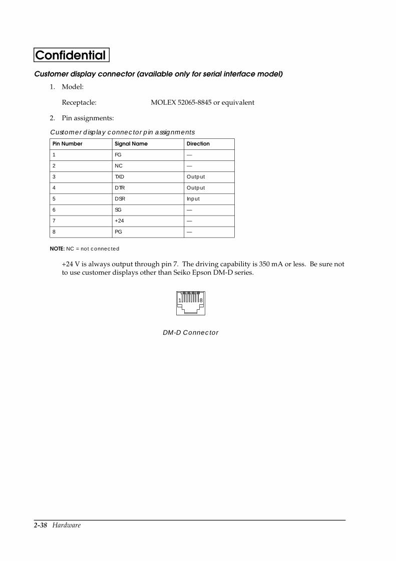
2-38 Hardware
ConfidentialCustomer display connector (available only for serial interface model)
1. Model:
Receptacle: MOLEX 52065-8845 or equivalent
2. Pin assignments:
NOTE: NC = not connected
+24 V is always output through pin 7. The driving capability is 350 mA or less. Be sure not to use customer displays other than Seiko Epson DM-D series.
DM-D Connector
Customer display connector pin assignments
Pin Number Signal Name Direction
1 FG —
2 NC —
3 TXD Output
4 DTR Output
5 DSR Input
6 SG —
7 +24 —
8 PG —
1 8
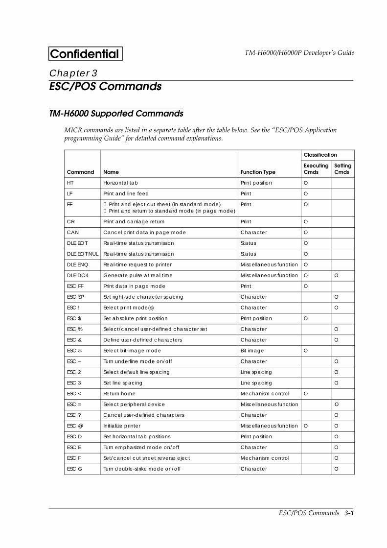
ESC/POS Commands 3-1
TM-H6000/H6000P Developer’s GuideConfidentialChapter 3ESC/POS Commands
TM-H6000 Supported Commands
MICR commands are listed in a separate table after the table below. See the “ESC/POS Application programming Guide” for detailed command explanations.
Command Name Function Type
Classification
ExecutingCmds
SettingCmds
HT Horizontal tab Print position O
LF Print and line feed Print O
FF ➀ Print and eject cut sheet (in standard mode)➁ Print and return to standard mode (in page mode)
Print O
CR Print and carriage return Print O
CAN Cancel print data in page mode Character O
DLE EOT Real-time status transmission Status O
DLE EOT NUL Real-time status transmission Status O
DLE ENQ Real-time request to printer Miscellaneous function O
DLE DC4 Generate pulse at real time Miscellaneous function O O
ESC FF Print data in page mode Print O
ESC SP Set right-side character spacing Character O
ESC ! Select print mode(s) Character O
ESC $ Set absolute print position Print position O
ESC % Select/cancel user-defined character set Character O
ESC & Define user-defined characters Character O
ESC Select bit-image mode Bit image O
ESC – Turn underline mode on/off Character O
ESC 2 Select default line spacing Line spacing O
ESC 3 Set line spacing Line spacing O
ESC < Return home Mechanism control O
ESC = Select peripheral device Miscellaneous function O
ESC ? Cancel user-defined characters Character O
ESC @ Initialize printer Miscellaneous function O O
ESC D Set horizontal tab positions Print position O
ESC E Turn emphasized mode on/off Character O
ESC F Set/cancel cut sheet reverse eject Mechanism control O
ESC G Turn double-strike mode on/off Character O
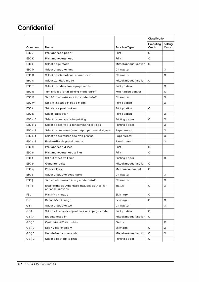
3-2 ESC/POS Commands
Confidential
ESC J Print and feed paper Print O
ESC K Print and reverse feed Print O
ESC L Select page mode Miscellaneous function O
ESC M Select character font Character O
ESC R Select an international character set Character O
ESC S Select standard mode Miscellaneous function O
ESC T Select print direction in page mode Print position O
ESC U Turn unidirectional printing mode on/off Mechanism control O
ESC V Turn 90 ° clockwise rotation mode on/off Character O
ESC W Set printing area in page mode Print position O
ESC \ Set relative print position Print position O
ESC a Select justification Print position O
ESC c 0 Select paper type(s) for printing Printing paper O O
ESC c 1 Select paper type(s) for command settings Printing paper O
ESC c 3 Select paper sensor(s) to output paper-end signals Paper sensor O
ESC c 4 Select paper sensor(s) to stop printing Paper sensor O
ESC c 5 Enable/disable panel buttons Panel button O
ESC d Print and feed n lines Print O
ESC e Print and reverse feed n lines Print O
ESC f Set cut sheet wait time Printing paper O
ESC p Generate pulse Miscellaneous function O
ESC q Paper release Mechanism control O
ESC t Select character code table Character O
ESC Turn upside-down printing mode on/off Character O
FS ( e Enable/disable Automatic Status Back (ASB) for optional functions
Status O O
FS p Print NV bit image Bit image O
FS q Define NV bit image Bit image O O
GS ! Select character size Character O
GS $ Set absolute vertical print position in page mode Print position O
GS ( A Execute test print Miscellaneous function O
GS ( B Customize ASB status bits Status O
GS ( C Edit NV user memory Bit image O O
GS ( E User-defined commands Miscellaneous function O O
GS ( G Select side of slip to print Printing paper O
Command Name Function Type
Classification
ExecutingCmds
SettingCmds

ESC/POS Commands 3-3
TM-H6000/H6000P Developer’s GuideConfidential
Note: NV = non-volatile
The following commands are supported only by printers with the optional Magnetic Ink Character Recognition (MICR) reader. (The MICR reader is a factory-installed option.)
GS ( L Transmit NV bit-image memory size Bit image O
GS Define downloaded bit image Bit image O
GS / Print downloaded bit image Bit image O
GS : Start/end macro definition Macro function O O
GS B Turn white/black reverse printing mode on/off Character O
GS E Select head control method Miscellaneous function O
GS H Select printing position of HRI characters Bar code O
GS I Transmit printer ID Miscellaneous function O
GS L Set left margin Print position O
GS P Set horizontal and vertical motion units Miscellaneous function O
GS T Set print position to the beginning of the print line Print position O
GS V Select cut mode and cut paper Mechanism control O
GS W Set printing area width Print position O
GS \ Set relative vertical print position in page mode Print position O
GS ^ Execute macro Macro function O
GS a Enable/disable Automatic Status Back (ASB) Status O
GS b Turn smoothing mode on/off Character O
GS f Select font for HRI characters Bar code O
GS g 0 Initialize maintenance counter Miscellaneous function O
GS g 2 Transmit maintenance counter Miscellaneous function O
GS h Set bar code height Bar code O
GS k Print bar code Bar code O
GS r Transmit status Status O
GS v 0 Print raster bit image Bit image O
GS w Set bar code width Bar code O
Command Name Function Type
Classification
ExecutingCmds
SettingCmds
DLE EOT BS Real-time MICR status transmission MICR O
FS ( f Select MICR data handling MICR O
FS a 0 Read check paper MICR O
FS a 1 Load check paper to print starting position MICR O
Command Name Function Type
Classification
ExecutingCmds
SettingCmds
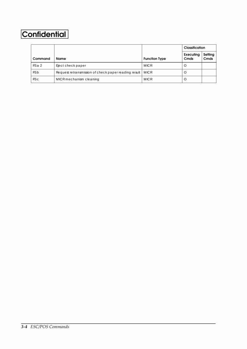
3-4 ESC/POS Commands
Confidential
FS a 2 Eject check paper MICR O
FS b Request retransmission of check paper reading result MICR O
FS c MICR mechanism cleaning MICR O
Command Name Function Type
Classification
ExecutingCmds
SettingCmds
Programming Guide/Tips 4-1
TM-H6000/H6000P Developer’s GuideConfidentialChapter 4Programming Guide/Tips
See the “ESC/POS Application Programming Guide” for a detailed command explanation.
Maintenance Counter
The maintenance counter can be used for assuming the time for replacing consumed parts or cleaning. The maintenance counter is transmitted by GS g 2 . Be sure to note that the value of the maintenance counter built in the printer is a reference value; therefore, there will be a difference in the value depending on the timing of occurring errors or turning off the power.
Bar Codes
Bar Code Printing
You can print bar codes, using the GS k command, for any of the following types of bar codes:
UPC-A, UPC-E
JAN 8 (EAN 8), JAN 13 (EAN 13)
CODE 39
ITF (Interleaved 2 of 5)
CODABAR (NW-7)
CODE 93
CODE 128
The bar codes types are described in further detail below.
UPC-A, UPC-E
These product distribution codes were established in the United States and are used in the U.S. and Canada. The codes are based on JAN codes and EAN codes. Although the paragraphs below explain the three existing types of UPC codes, you can use only UPC-A and UPC-E with the TM-H6000.
UPC-A
This code is very similar to the JAN 13 (EAN 13) code, and consists of the code for a 12-digit number. The standard value for the first digit is “0.” When coding is performed at the store, the first digit is “2.” The first digit is “3” for NDC (National Drug Code) and HRI (National Health Related Items Code) items. “4” is used for items protected by a check digit, and “5” is used for coupons. No standards have been determined for other items.

4-2 Programming Guide/Tips
Confidential UPC-D
Since only 12 digits can be used with UPC-A, UPC-D was established to allow the number of digits to be increased. Currently, it is not being used (and it cannot be used with the TM-H6000).
UPC-E
This is an abbreviated bar code, in which bar codes created using the UPC-A standard are shortened by deleting data values of “0” according to certain rules.
Usage
You can use only numbers between 0 and 9. The bar code itself can be 11 or 12 digits long. When the bar code is 11 digits, a check character is assigned automatically, for a total of 12 digits.
JAN 8 (EAN 8), JAN 13 (EAN 13)
These are UPC-compliant common product codes used in Japan and Europe. These codes are seen very frequently since they are printed on ordinary products.
Usage
You can use only numbers between 0 and 9. The bar code itself is 8 digits (JAN 8, EAN 8) or 13 digits (JAN 13, EAN 13) long. If the code for either of these two types of codes is one digit less than 8 or 13, a check character is added automatically to make the code 8 or 13 digits.
CODE 39
This bar code consists of thick and thin bars, and spaces between them. There are five bars and four spaces, for a total of nine. “” is used as the start code and stop code, and the codes between the “” marks are the data.
Usage
You can use numbers between 0 and 9, letters and special codes (-, +, $, %, /, ., and space). The number of bar code digits differs, depending on command parameter m. There are no limitations on the number of digits, or up to 255 digits. A check digit is not added.
ITF (Interleaved 2 of 5)
CODE 39 uses thick and thin bars. Odd numbers are expressed with bars, and even numbers with spaces. Therefore, as a rule, there are only even-digit bar codes.
Usage
You can use numbers between 0 and 9. The number of bar code digits differs, depending on command parameter m. There are no limitations on the number of digits, up to 254 digits.
Printing is not performed when an odd data number is specified. However, when parameter m = 5, and an odd number is specified, printing is performed, with the last character being discarded.
No check digit is added.

Programming Guide/Tips 4-3
TM-H6000/H6000P Developer’s GuideConfidentialCODABAR (NW-7)
One character is expressed with the NW-7 code by four thick and thin bars and 3 spaces, for a total of seven lines. This code has been used for a long time, due to its relatively simple configuration and the low printing precision requirements.
Usage
You can use numbers between 0 and 9, and six special codes (-, $, :, /, ., +). Four start/stop codes (A - D) can be used, and configured as desired.
CODE 93
This bar code was developed to shorten the Code 39 bar code. It consists of four bars and spaces.
Usage
You can use all ASCII code characters (0 - 127) for data, and you can set a bar code of up to 255 digits. A check digit is assigned automatically.
CODE 128
This bar code was developed to shorten the Code 39 bar code and increase the reliability of data. It consists of four bars and spaces.
Usage
You can use all ASCII code characters (0 - 127), and you can set a bar code of up to 255 digits. A check digit is assigned automatically.
The code set selection character must be at the beginning of the data string. It is two characters (2 bytes). “A” is used to select code A, “B” is used to select code B, “C” is used to select code C. Accordingly, the shortest data string is two characters. Other special characters are also specified by two characters starting with “.” To specify a bracket (), you use a double bracket ().
Bar Code Height
You can set the bar code height between 1 dot and 255 dots (35.9 mm or 1.4 in) with the GS h command. The initial value is 162 dots (22.8 mm or 0.9 in).

4-4 Programming Guide/Tips
ConfidentialType of Bar Code, Relationship of Number of Characters, and Horizontal Width
You can set the horizontal width of the bar code to between 2 and 6 with the GS w command (The actual width changes, depending on the type and number of digits.), but printing cannot exceed the paper width. The table below indicates whether or not printing can be performed for the respective bar code horizontal widths.
HRI Character Printing
You can print HRI (Human Readable Interpretation) characters above or below the bar code by sending the GS H command. Select font A or B at this time for printing with the GS f command. The initial setting is font A.
Customizing the ASB Status Bit
ASB Status Bit Allocation
Bit 0 and bit 1, and bit 2 and bit 3 of the third ASB byte have the same meaning on the TM-H6000. The reason for this is to maintain send status compatibility with the TM-H5000II and other printers. However, only one bit is needed to indicate the status, allowing the other bit to be used for a different status. This enables the adding of a new command.
Bit 1 and bit 3 of the third byte can be changed, and the following functions can be allocated:
Bit 1 : Waiting for insertion of single sheet status
Bit 3 : Waiting for removal of single sheet status
No. of DigitsLimit Horizontal Width Specification (GS w n) n= Remarks
2 3 4 5 6
UPC-A 12 Printing possible
Printing possible
Printing possible
Printing possible
Printing not possible
UPC-E 12 Printing possible
Printing possible
Printing possible
Printing possible
Printing possible
JAN 13 13 Printing possible
Printing possible
Printing possible
Printing possible
Printing not possible
JAN 8 8 Printing possible
Printing possible
Printing possible
Printing possible
Printing possible
CODE 39 None 16 digits 10 digits 6 digits 4 digits 3 digits
ITF Even 30 digits 18 digits 14 digits 10 digits 8 digits
CODABAR (NW-7)
None 21 digits 12 digits 9 digits 6 digits 5 digits Excluding START/ STOP codes
CODE 93 None 24 digits 14 digits 10 digits 7 digits 5 digits
CODE 128 None 20 digits 13 digits 8 digits 6 digits 4 digits Double for code set C
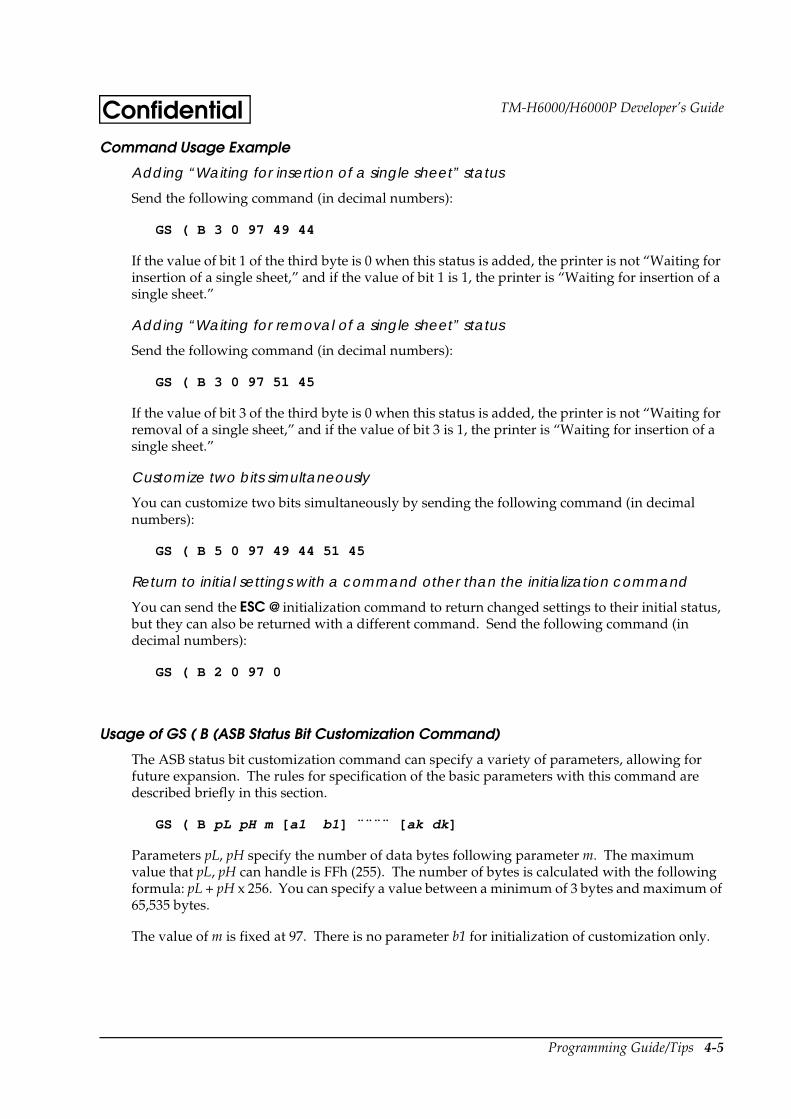
Programming Guide/Tips 4-5
TM-H6000/H6000P Developer’s GuideConfidentialCommand Usage Example
Adding “Waiting for insertion of a single sheet” status
Send the following command (in decimal numbers):
GS ( B 3 0 97 49 44
If the value of bit 1 of the third byte is 0 when this status is added, the printer is not “Waiting for insertion of a single sheet,” and if the value of bit 1 is 1, the printer is “Waiting for insertion of a single sheet.”
Adding “Waiting for removal of a single sheet” status
Send the following command (in decimal numbers):
GS ( B 3 0 97 51 45
If the value of bit 3 of the third byte is 0 when this status is added, the printer is not “Waiting for removal of a single sheet,” and if the value of bit 3 is 1, the printer is “Waiting for insertion of a single sheet.”
Customize two bits simultaneously
You can customize two bits simultaneously by sending the following command (in decimal numbers):
GS ( B 5 0 97 49 44 51 45
Return to initial settings with a command other than the initialization command
You can send the ESC @ initialization command to return changed settings to their initial status, but they can also be returned with a different command. Send the following command (in decimal numbers):
GS ( B 2 0 97 0
Usage of GS ( B (ASB Status Bit Customization Command)
The ASB status bit customization command can specify a variety of parameters, allowing for future expansion. The rules for specification of the basic parameters with this command are described briefly in this section.
GS ( B pL pH m [ a1 b1] ¨¨¨¨ [ ak dk ]
Parameters pL, pH specify the number of data bytes following parameter m. The maximum value that pL, pH can handle is FFh (255). The number of bytes is calculated with the following formula: pL + pH x 256. You can specify a value between a minimum of 3 bytes and maximum of 65,535 bytes.
The value of m is fixed at 97. There is no parameter b1 for initialization of customization only.
4-6 Programming Guide/Tips
ConfidentialStatus Commands
Four types of commands can be used to confirm the status of the TM-H6000 printer. This section describes the differences for the respective commands and effective uses.
Status Send Request Command (GS r)
This command is stored in the TM receive buffer and is processed following the commands that were previously sent. It enables checking of whether or not there is a paper roll and paper slip, and checking of the drawer kick connector status.
In addition to the normal status check functions, by adding this command at the end of a series of commands, you can check whether or not that series of commands was processed and whether or not any data remains in the receive buffer.
Status Real Time Send Request Command (DLE EOT)
This command is processed before it is stored in the TM receive buffer, and the status is sent back immediately. You can check the status of various printer functions, whether or not there is paper, and error status. However, the TM side will go to the Busy status when an error is triggered by no paper or other such status, preventing data from being sent. Therefore, it is necessary for this command to be sent, ignoring the handshake for the serial I/F. Furthermore, the command cannot be sent by ignoring the Busy status with the parallel I/F.
After this command is processed, it is temporarily stored in the receive buffer. This is a consideration in case the command may be a portion of bitmap data. Accordingly, there is a possibility that this command alone may fill up the receive buffer when the printer is waiting for insertion of a slip. So, note the following points:
Stop sending of the DLE command when the printer is waiting for slip insertion, or provide an ample interval between commands.
Monitor the TOF and BOF sensors, and select slip mode after a slip is inserted.
Status Automatic Send Setting Command (GS a)
After this command is sent, the TM automatically sends the status every time the specified status changes. When using this command, it is necessary to monitor the PC receive buffer constantly so that changes in status are not overlooked.
MICR Status Real Time Send (DLE EOT BS)
Like the DLE EOT command, this command is processed before it is stored in the TM receive buffer, and the status is immediately sent back. You can check the following types of status: selection/non-selection of MICR, whether or not a cleaning sheet has been inserted, and other MICR related information.
However, when no paper or another cause has triggered an error, or when the receive buffer is full, the TM side will go to the Busy status, preventing data from being sent. Therefore, follow the same precautions as for the DLE EOT command.
Programming Guide/Tips 4-7
TM-H6000/H6000P Developer’s GuideConfidentialBit Image Commands
The following are the bit image printing and setting commands:
ESC print only one bit image line command
GS v 0 print raster bit image command
GS download bit image registration command
GS / download bit image print command
FS q NV bit image registration command
FS p NV bit image print command
Bit Image Print Command (ESC )
Types of paper for printing
You can print on paper rolls and on the front or back of slips.
Printing size
Printing is one row of an eight-dot high bit image.
Download Bit Image Registration/Printing Commands (GS , GS /)
Types of paper for printing
You can print on paper rolls and on the front of slips.
Printing size
After defining an 8 x 8 dot bit image as the minimum unit, you can print in the normal, double vertical, double horizontal, and quadruple modes by using the appropriate print commands.
NV Bit Image Registration/Printing Command (FS q, FS p /)
Types of paper for printing
Printing can be on paper rolls and on the front of slips.
Printing size
After defining an 8 x 8 dot bit image as the minimum unit, you can print in the normal, double vertical, double horizontal, and quadruple modes by using the appropriate print commands.
Limitations
The TM-H6000 can use NV bit images for slips. However, there is no data in the bit image data area to differentiate thermal images from slip images. Therefore, the user must remember which type of bit image the data is for.

4-8 Programming Guide/Tips
ConfidentialRaster Bit Image Print Command (GS v 0)
Types of paper for printing
You can print on paper rolls and on the front of slips.
Printing size
The minimum unit is an 8-dot unit 1-dot row bit image.
Bit Image Command ESC
One horizontal line of bit data is printed.
Command configuration
ESC m nL nH d1 ¨¨¨¨ dk
(The value of k (data quantity) changes, depending on m, nL, nH.)
The relationship of the value of m to the printing area and the resulting print density are shown in the following table:
m ModeVD Data Paper Roll Slip (front) Slip (back)
Usage VDD HDD Usage VDD HDD Usage VDD HDD
0 8-dot single-density
1 byte Yes 60 dpi 90 dpi Yes 72 dpi 80 dpi Yes 72 dpi 127 dpi
1 8-dot double-density
1 byte Yes 60 dpi 180 dpi Yes 72 dpi 160 dpi No — —
32 24-dot single-density
3 byte Yes 180 dpi 90 dpi No — — No — —
33 24-dot single-density
3 byte Yes 180 dpi 180 dpi No — — No — —
VD: Vertical Direction Yes: Possible No: Not possible VDD: Vertical Dot Density HDD: Horizontal Dot Density
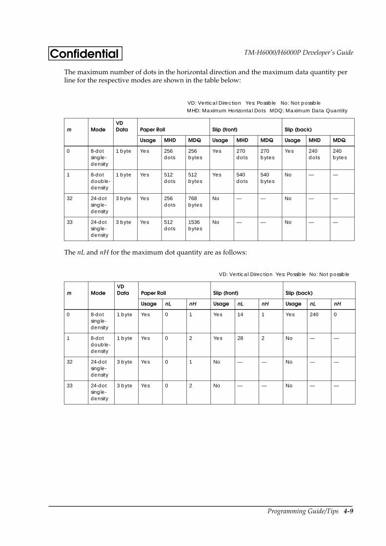
Programming Guide/Tips 4-9
TM-H6000/H6000P Developer’s GuideConfidentialThe maximum number of dots in the horizontal direction and the maximum data quantity per line for the respective modes are shown in the table below:
The nL and nH for the maximum dot quantity are as follows:
m ModeVD Data Paper Roll Slip (front) Slip (back)
Usage MHD MDQ Usage MHD MDQ Usage MHD MDQ
0 8-dot single-density
1 byte Yes 256 dots
256 bytes
Yes 270 dots
270 bytes
Yes 240 dots
240 bytes
1 8-dot double-density
1 byte Yes 512 dots
512 bytes
Yes 540 dots
540 bytes
No — —
32 24-dot single-density
3 byte Yes 256 dots
768 bytes
No — — No — —
33 24-dot single-density
3 byte Yes 512 dots
1536 bytes
No — — No — —
m ModeVD Data Paper Roll Slip (front) Slip (back)
Usage nL nH Usage nL nH Usage nL nH
0 8-dot single-density
1 byte Yes 0 1 Yes 14 1 Yes 240 0
1 8-dot double-density
1 byte Yes 0 2 Yes 28 2 No — —
32 24-dot single-density
3 byte Yes 0 1 No — — No — —
33 24-dot single-density
3 byte Yes 0 2 No — — No — —
VD: Vertical Direction Yes: Possible No: Not possible
MHD: Maximum Horizontal Dots MDQ: Maximum Data Quantity
VD: Vertical Direction Yes: Possible No: Not possible
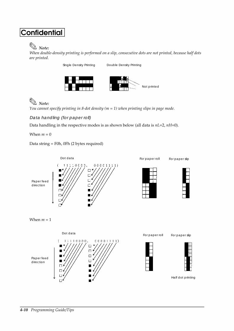
4-10 Programming Guide/Tips
Confidential
Note:When double-density printing is performed on a slip, consecutive dots are not printed, because half dots are printed.
Note:You cannot specify printing in 8-dot density (m = 1) when printing slips in page mode.
Data handling (for paper roll)
Data handling in the respective modes is as shown below (all data is nL=2, nH=0).
When m = 0
Data string = F0h, 0Fh (2 bytes required)
When m = 1
Single Density Printing Double Density Printing
Not printed
Paper feed direction
For paper slipDot data For paper roll
Dot dataFor paper slip
Half dot printing
Paper feed direction
For paper roll
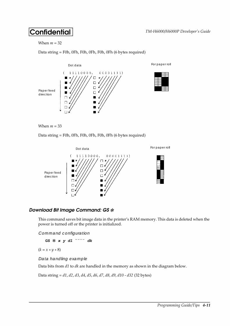
Programming Guide/Tips 4-11
TM-H6000/H6000P Developer’s GuideConfidentialWhen m = 32
Data string = F0h, 0Fh, F0h, 0Fh, F0h, 0Fh (6 bytes required)
When m = 33
Data string = F0h, 0Fh, F0h, 0Fh, F0h, 0Fh (6 bytes required)
Download Bit Image Command: GS
This command saves bit image data in the printer’s RAM memory. This data is deleted when the power is turned off or the printer is initialized.
Command configuration
GS x y d1 ¨¨¨¨ dk
(k = x × y × 8)
Data handling example
Data bits from d1 to dk are handled in the memory as shown in the diagram below.
Data string = d1, d2, d3, d4, d5, d6, d7, d8, d9, d10 - d32 (32 bytes)
Dot data For paper roll
Paper feed direction
Dot data For paper roll
Paper feed direction

4-12 Programming Guide/Tips
ConfidentialFor x = 1, y = 4
For x = 2, y = 2
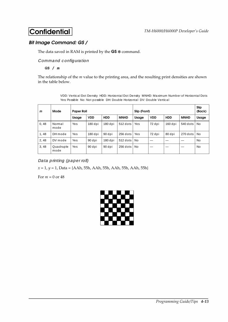
Programming Guide/Tips 4-13
TM-H6000/H6000P Developer’s GuideConfidentialBit Image Command: GS /
The data saved in RAM is printed by the GS command.
Command configuration
GS / m
The relationship of the m value to the printing area, and the resulting print densities are shown in the table below.
Data printing (paper roll)
x = 1, y = 1, Data = AAh, 55h, AAh, 55h, AAh, 55h, AAh, 55h
For m = 0 or 48
m Mode Paper Roll Slip (Front)Slip (Back)
Usage VDD HDD MNHD Usage VDD HDD MNHD Usage
0, 48 Normal mode
Yes 180 dpi 180 dpi 512 dots Yes 72 dpi 160 dpi 540 dots No
1, 48 DH mode Yes 180 dpi 90 dpi 256 dots Yes 72 dpi 80 dpi 270 dots No
2, 48 DV mode Yes 90 dpi 180 dpi 512 dots No — — — No
3, 48 Quadruple mode
Yes 90 dpi 90 dpi 256 dots No — — — No
VDD: Vertical Dot Density HDD: Horizontal Dot Density MNHD: Maximum Number of Horizontal DotsYes: Possible No: Not possible DH: Double Horizontal DV: Double Vertical
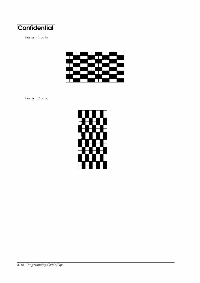
4-14 Programming Guide/Tips
ConfidentialFor m = 1 or 49
For m = 2 or 50
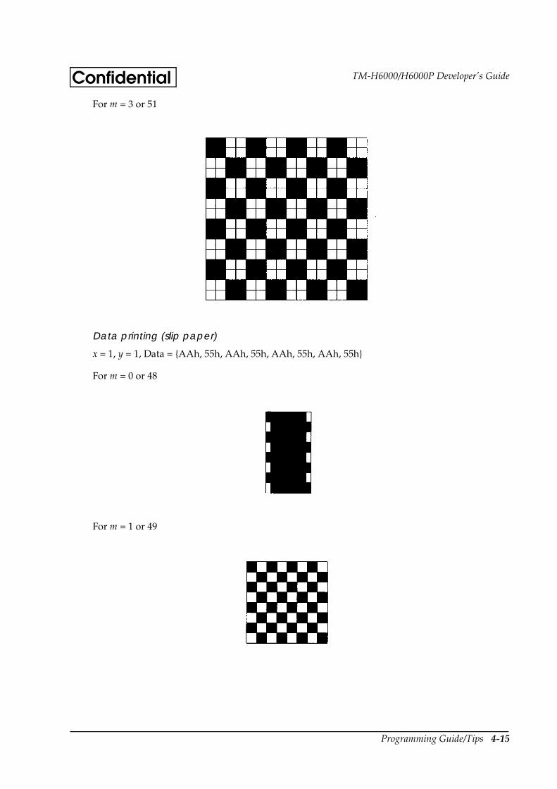
Programming Guide/Tips 4-15
TM-H6000/H6000P Developer’s GuideConfidentialFor m = 3 or 51
Data printing (slip paper)
x = 1, y = 1, Data = AAh, 55h, AAh, 55h, AAh, 55h, AAh, 55h
For m = 0 or 48
For m = 1 or 49

4-16 Programming Guide/Tips
Confidential
Note:Half dots are printed when printing on slips in the normal mode (m = 0). Therefore, consecutive dots are not printed.
Note:When slips are printed in page mode, the normal mode (m = 0) cannot be specified.
NV Bit Image Command: FS q
This command stores bit data in the TM printer’s non-volatile memory. Please note that all data cannot be stored at one time. You can save bit images for both paper roll and slip, but you must manage which image is used in which mode for printing.
Command configuration
FS q n [ xL xH yL yH d1 ¨¨¨¨ dk ]1 ¨¨¨¨ [ xL xH yL yH d1 ¨¨¨¨ dk ] n
(Value of k changes depending on xL, xH, yL, yH.)
Data handling
Handling of bit image data is the same as with the GS command.
NV Bit Image Command: FS p
Data stored in NV memory is printed with the FS p command.
Command configuration
FS p n m
Normal Mode Printing Double Horizontal Mode Printing
Not printed
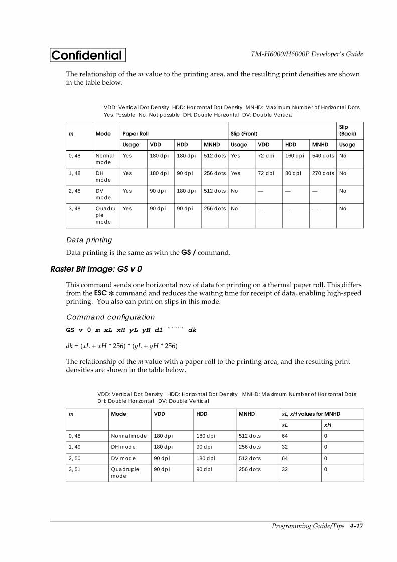
Programming Guide/Tips 4-17
TM-H6000/H6000P Developer’s GuideConfidentialThe relationship of the m value to the printing area, and the resulting print densities are shown in the table below.
Data printing
Data printing is the same as with the GS / command.
Raster Bit Image: GS v 0
This command sends one horizontal row of data for printing on a thermal paper roll. This differs from the ESC command and reduces the waiting time for receipt of data, enabling high-speed printing. You also can print on slips in this mode.
Command configuration
GS v 0 m xL xH yL yH d1 ¨¨¨¨ dk
dk = (xL + xH * 256) * (yL + yH * 256)
The relationship of the m value with a paper roll to the printing area, and the resulting print densities are shown in the table below.
m Mode Paper Roll Slip (Front)Slip (Back)
Usage VDD HDD MNHD Usage VDD HDD MNHD Usage
0, 48 Normal mode
Yes 180 dpi 180 dpi 512 dots Yes 72 dpi 160 dpi 540 dots No
1, 48 DH mode
Yes 180 dpi 90 dpi 256 dots Yes 72 dpi 80 dpi 270 dots No
2, 48 DV mode
Yes 90 dpi 180 dpi 512 dots No — — — No
3, 48 Quadruple mode
Yes 90 dpi 90 dpi 256 dots No — — — No
m Mode VDD HDD MNHD xL, xH values for MNHD
xL xH
0, 48 Normal mode 180 dpi 180 dpi 512 dots 64 0
1, 49 DH mode 180 dpi 90 dpi 256 dots 32 0
2, 50 DV mode 90 dpi 180 dpi 512 dots 64 0
3, 51 Quadruple mode
90 dpi 90 dpi 256 dots 32 0
VDD: Vertical Dot Density HDD: Horizontal Dot Density MNHD: Maximum Number of Horizontal DotsYes: Possible No: Not possible DH: Double Horizontal DV: Double Vertical
VDD: Vertical Dot Density HDD: Horizontal Dot Density MNHD: Maximum Number of Horizontal DotsDH: Double Horizontal DV: Double Vertical
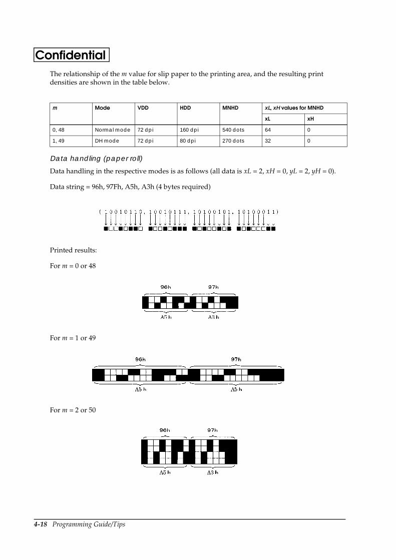
4-18 Programming Guide/Tips
ConfidentialThe relationship of the m value for slip paper to the printing area, and the resulting print densities are shown in the table below.
Data handling (paper roll)
Data handling in the respective modes is as follows (all data is xL = 2, xH = 0, yL = 2, yH = 0).
Data string = 96h, 97Fh, A5h, A3h (4 bytes required)
Printed results:
For m = 0 or 48
For m = 1 or 49
For m = 2 or 50
m Mode VDD HDD MNHD xL, xH values for MNHD
xL xH
0, 48 Normal mode 72 dpi 160 dpi 540 dots 64 0
1, 49 DH mode 72 dpi 80 dpi 270 dots 32 0
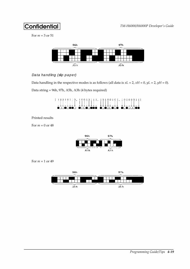
Programming Guide/Tips 4-19
TM-H6000/H6000P Developer’s GuideConfidentialFor m = 3 or 51
Data handling (slip paper)
Data handling in the respective modes is as follows (all data is xL = 2, xH = 0, yL = 2, yH = 0).
Data string = 96h, 97h, A5h, A3h (4 bytes required)
Printed results
For m = 0 or 48
For m = 1 or 49
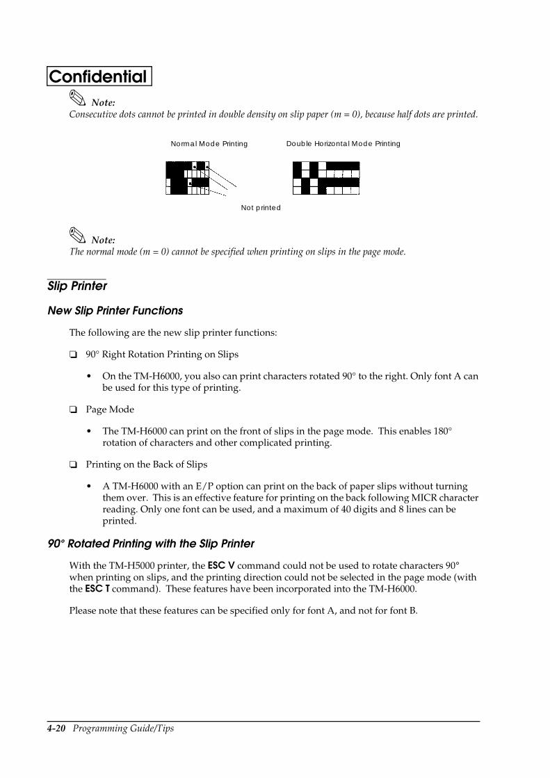
4-20 Programming Guide/Tips
ConfidentialNote:
Consecutive dots cannot be printed in double density on slip paper (m = 0), because half dots are printed.
Note:The normal mode (m = 0) cannot be specified when printing on slips in the page mode.
Slip Printer
New Slip Printer Functions
The following are the new slip printer functions:
90° Right Rotation Printing on Slips
• On the TM-H6000, you also can print characters rotated 90° to the right. Only font A can be used for this type of printing.
Page Mode
• The TM-H6000 can print on the front of slips in the page mode. This enables 180° rotation of characters and other complicated printing.
Printing on the Back of Slips
• A TM-H6000 with an E/P option can print on the back of paper slips without turning them over. This is an effective feature for printing on the back following MICR character reading. Only one font can be used, and a maximum of 40 digits and 8 lines can be printed.
90° Rotated Printing with the Slip Printer
With the TM-H5000 printer, the ESC V command could not be used to rotate characters 90° when printing on slips, and the printing direction could not be selected in the page mode (with the ESC T command). These features have been incorporated into the TM-H6000.
Please note that these features can be specified only for font A, and not for font B.
Normal Mode Printing Double Horizontal Mode Printing
Not printed
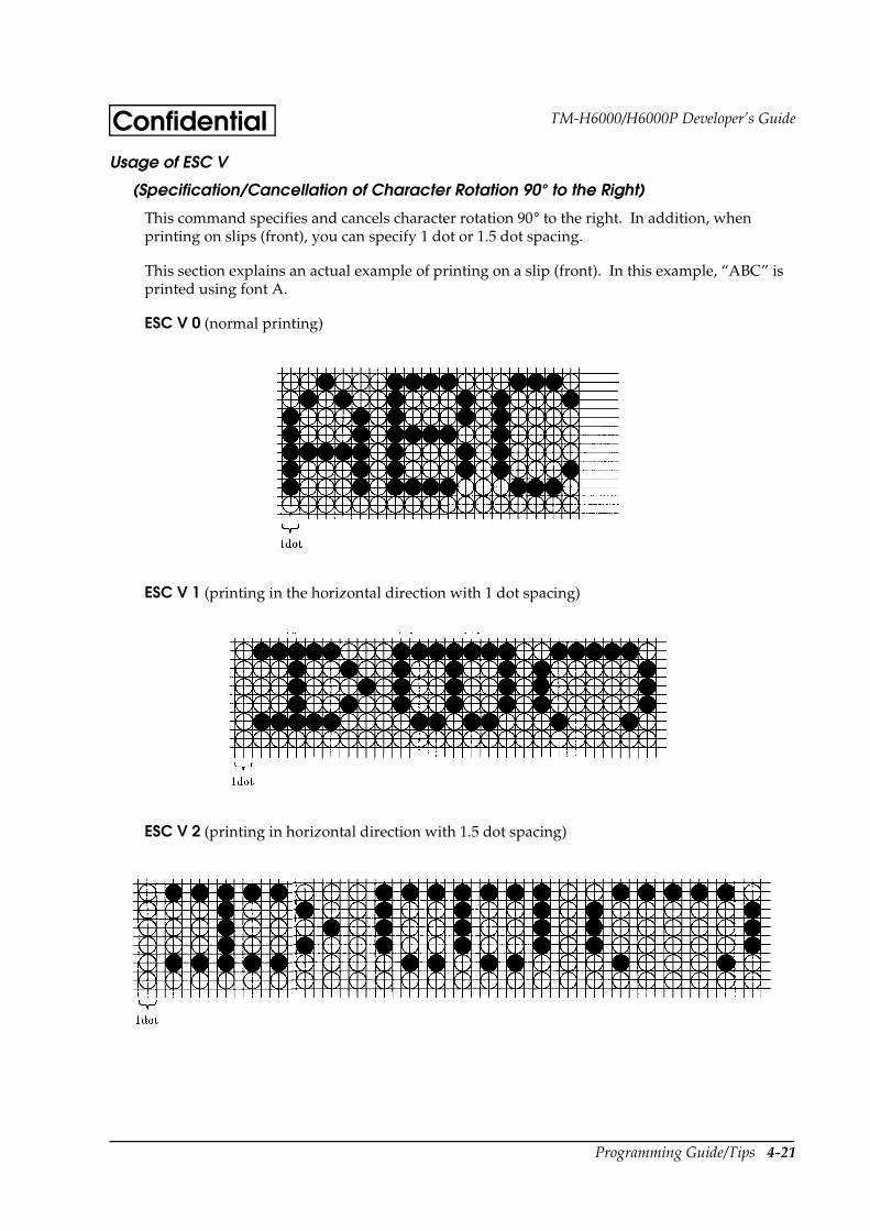
Programming Guide/Tips 4-21
TM-H6000/H6000P Developer’s GuideConfidentialUsage of ESC V
(Specification/Cancellation of Character Rotation 90° to the Right)
This command specifies and cancels character rotation 90° to the right. In addition, when printing on slips (front), you can specify 1 dot or 1.5 dot spacing.
This section explains an actual example of printing on a slip (front). In this example, “ABC” is printed using font A.
ESC V 0 (normal printing)
ESC V 1 (printing in the horizontal direction with 1 dot spacing)
ESC V 2 (printing in horizontal direction with 1.5 dot spacing)
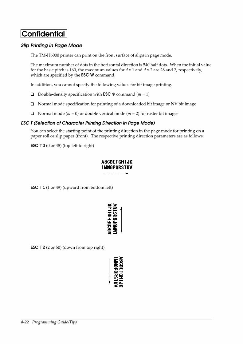
4-22 Programming Guide/Tips
ConfidentialSlip Printing in Page Mode
The TM-H6000 printer can print on the front surface of slips in page mode.
The maximum number of dots in the horizontal direction is 540 half dots. When the initial value for the basic pitch is 160, the maximum values for d x 1 and d x 2 are 28 and 2, respectively, which are specified by the ESC W command.
In addition, you cannot specify the following values for bit image printing.
Double-density specification with ESC command (m = 1)
Normal mode specification for printing of a downloaded bit image or NV bit image
Normal mode (m = 0) or double vertical mode (m = 2) for raster bit images
ESC T (Selection of Character Printing Direction in Page Mode)
You can select the starting point of the printing direction in the page mode for printing on a paper roll or slip paper (front). The respective printing direction parameters are as follows:
ESC T 0 (0 or 48) (top left to right)
ESC T 1 (1 or 49) (upward from bottom left)
ESC T 2 (2 or 50) (down from top right)
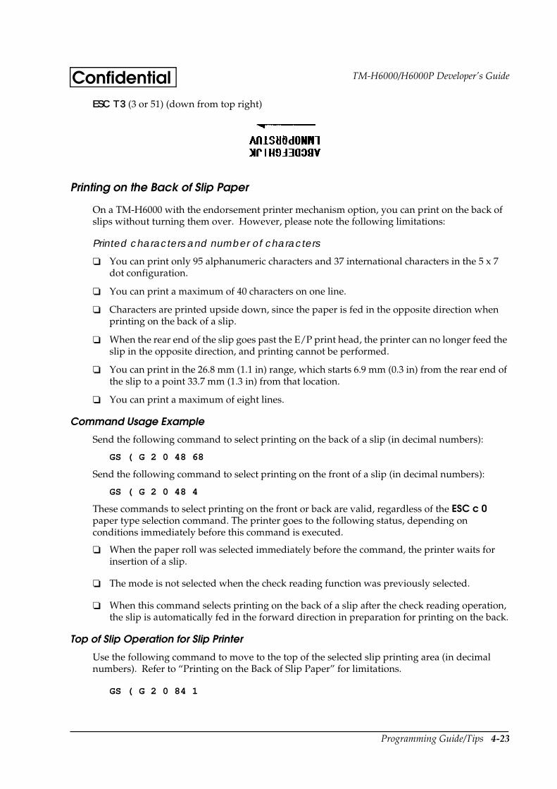
Programming Guide/Tips 4-23
TM-H6000/H6000P Developer’s GuideConfidentialESC T 3 (3 or 51) (down from top right)
Printing on the Back of Slip Paper
On a TM-H6000 with the endorsement printer mechanism option, you can print on the back of slips without turning them over. However, please note the following limitations:
Printed characters and number of characters
You can print only 95 alphanumeric characters and 37 international characters in the 5 x 7 dot configuration.
You can print a maximum of 40 characters on one line.
Characters are printed upside down, since the paper is fed in the opposite direction when printing on the back of a slip.
When the rear end of the slip goes past the E/P print head, the printer can no longer feed the slip in the opposite direction, and printing cannot be performed.
You can print in the 26.8 mm (1.1 in) range, which starts 6.9 mm (0.3 in) from the rear end of the slip to a point 33.7 mm (1.3 in) from that location.
You can print a maximum of eight lines.
Command Usage Example
Send the following command to select printing on the back of a slip (in decimal numbers):
GS ( G 2 0 48 68
Send the following command to select printing on the front of a slip (in decimal numbers):
GS ( G 2 0 48 4
These commands to select printing on the front or back are valid, regardless of the ESC c 0 paper type selection command. The printer goes to the following status, depending on conditions immediately before this command is executed.
When the paper roll was selected immediately before the command, the printer waits for insertion of a slip.
The mode is not selected when the check reading function was previously selected.
When this command selects printing on the back of a slip after the check reading operation, the slip is automatically fed in the forward direction in preparation for printing on the back.
Top of Slip Operation for Slip Printer
Use the following command to move to the top of the selected slip printing area (in decimal numbers). Refer to “Printing on the Back of Slip Paper” for limitations.
GS ( G 2 0 84 1
4-24 Programming Guide/Tips
ConfidentialThis command is also valid after printing on the front of a slip is selected with the ESC c 0 command.
NV User Memory
Since a Flash ROM is used for the NV memory, the data is not lost when power is turned off. Therefore, saving the data for bit images that are printed regularly eliminates the need to download the data, saving time. There is also an NV user area for data in the memory that can be used for a memo or other purposes.
The initial values for the memory areas are as follows: 384 KB for the NV bit image area and 1 KB for the NV user area. You can change these sizes with the GS ( E command, depending on the particular application.
Editing of NV User Memory
You can store a variety of data in the NV user memory, but there are the following limitations:
You can specify a data size between 1 byte and 65530 bytes, but data that exceeds the remaining memory capacity cannot be saved. In this case, the command is ignored.
You can add a two-byte key code to identify the stored data and a 1-byte code to divide data added. Therefore, stored data uses the total data amount + 3 bytes of memory. This group of data is called a record.
Key codes are defined as K1, K2, etc., in the example command, but you can actually use any ASCII codes from 32 to 126. These correspond to the characters from “Space” to “~.”
ASCII codes from 32 to 254 can be handled as data. These correspond to characters starting with “Space.”
When the same key already exists, it is overwritten.
If you send a command containing key input only (without any data), it cannot be written as a record.
The printer sends data every 80 bytes. (In actual practice, a maximum of 83 bytes are sent at a time, which consist of the data, plus 1 byte for the header, 1 byte for the identifier, 1 status byte, and 1 terminator byte following the data.)
There are two types of status when data is sent: 40h and 41h. 40h indicates no data follows, and 41h indicates there is more data.
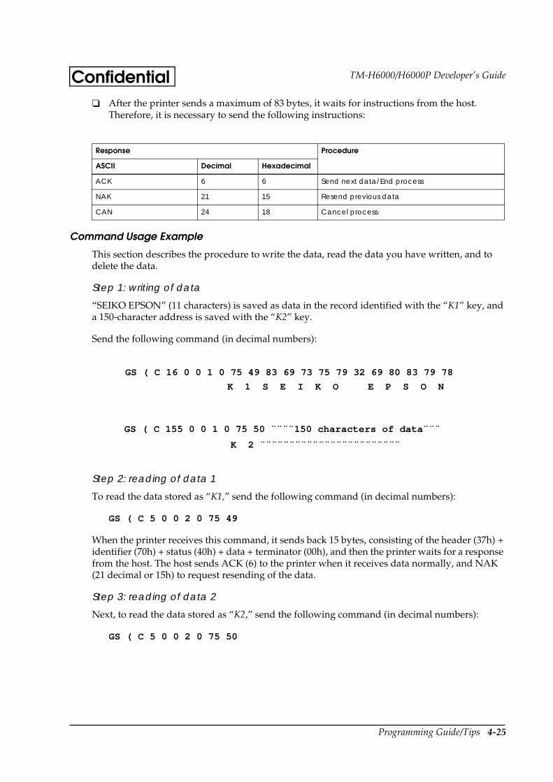
Programming Guide/Tips 4-25
TM-H6000/H6000P Developer’s GuideConfidential After the printer sends a maximum of 83 bytes, it waits for instructions from the host.
Therefore, it is necessary to send the following instructions:
Command Usage Example
This section describes the procedure to write the data, read the data you have written, and to delete the data.
Step 1: writing of data
“SEIKO EPSON” (11 characters) is saved as data in the record identified with the “K1” key, and a 150-character address is saved with the “K2” key.
Send the following command (in decimal numbers):
Step 2: reading of data 1
To read the data stored as “K1,” send the following command (in decimal numbers):
GS ( C 5 0 0 2 0 75 49
When the printer receives this command, it sends back 15 bytes, consisting of the header (37h) + identifier (70h) + status (40h) + data + terminator (00h), and then the printer waits for a response from the host. The host sends ACK (6) to the printer when it receives data normally, and NAK (21 decimal or 15h) to request resending of the data.
Step 3: reading of data 2
Next, to read the data stored as “K2,” send the following command (in decimal numbers):
GS ( C 5 0 0 2 0 75 50
Response Procedure
ASCII Decimal Hexadecimal
ACK 6 6 Send next data/End process
NAK 21 15 Resend previous data
CAN 24 18 Cancel process
GS ( C 16 0 0 1 0 75 49 83 69 73 75 79 32 69 80 83 79 78
K 1 S E I K O E P S O N
GS ( C 155 0 0 1 0 75 50 ¨¨¨¨150 characters of data¨¨¨
K 2 ¨¨¨¨¨¨¨¨¨¨¨¨¨¨¨¨¨¨¨¨¨¨¨¨
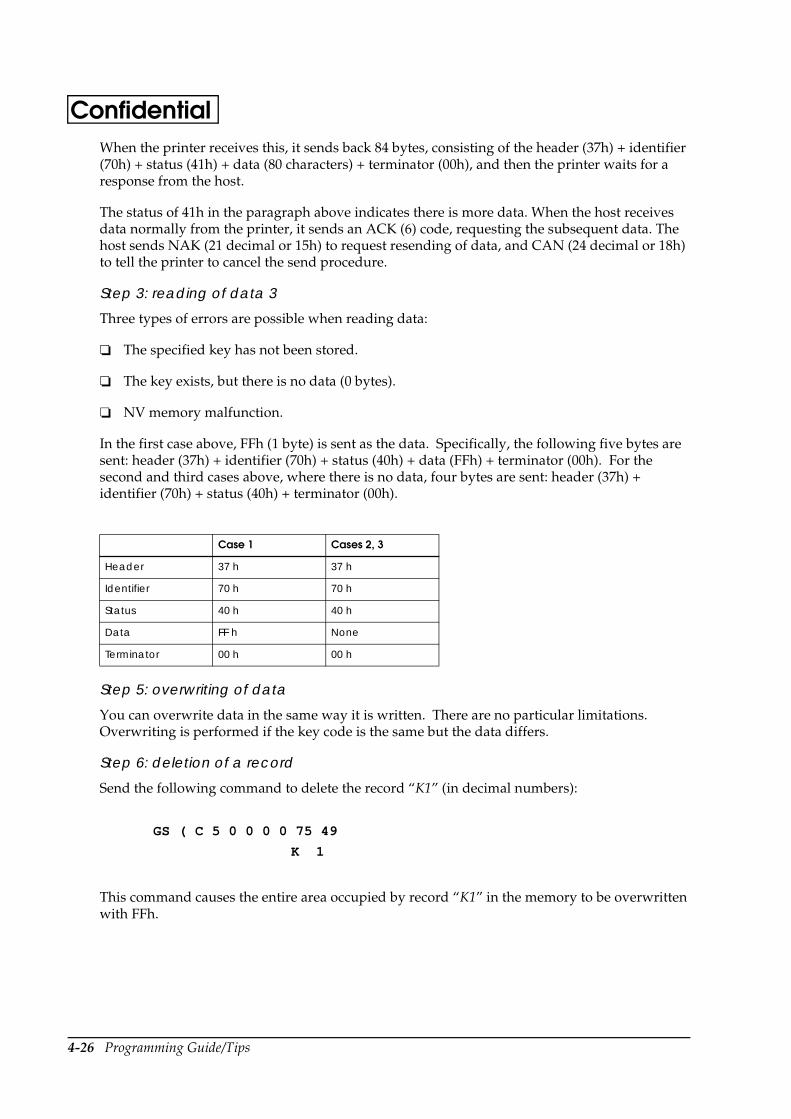
4-26 Programming Guide/Tips
ConfidentialWhen the printer receives this, it sends back 84 bytes, consisting of the header (37h) + identifier (70h) + status (41h) + data (80 characters) + terminator (00h), and then the printer waits for a response from the host.
The status of 41h in the paragraph above indicates there is more data. When the host receives data normally from the printer, it sends an ACK (6) code, requesting the subsequent data. The host sends NAK (21 decimal or 15h) to request resending of data, and CAN (24 decimal or 18h) to tell the printer to cancel the send procedure.
Step 3: reading of data 3
Three types of errors are possible when reading data:
The specified key has not been stored.
The key exists, but there is no data (0 bytes).
NV memory malfunction.
In the first case above, FFh (1 byte) is sent as the data. Specifically, the following five bytes are sent: header (37h) + identifier (70h) + status (40h) + data (FFh) + terminator (00h). For the second and third cases above, where there is no data, four bytes are sent: header (37h) + identifier (70h) + status (40h) + terminator (00h).
Step 5: overwriting of data
You can overwrite data in the same way it is written. There are no particular limitations. Overwriting is performed if the key code is the same but the data differs.
Step 6: deletion of a record
Send the following command to delete the record “K1” (in decimal numbers):
This command causes the entire area occupied by record “K1” in the memory to be overwritten with FFh.
Case 1 Cases 2, 3
Header 37 h 37 h
Identifier 70 h 70 h
Status 40 h 40 h
Data FF h None
Terminator 00 h 00 h
GS ( C 5 0 0 0 0 75 49
K 1
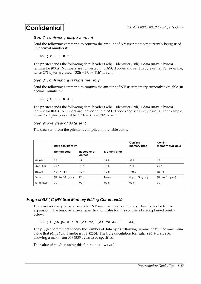
Programming Guide/Tips 4-27
TM-H6000/H6000P Developer’s GuideConfidentialStep 7: confirming usage amount
Send the following command to confirm the amount of NV user memory currently being used (in decimal numbers):
GS ( C 3 0 0 3 0
The printer sends the following data: header (37h) + identifier (28h) + data (max. 8 bytes) + terminator (00h). Numbers are converted into ASCII codes and sent in byte units. For example, when 271 bytes are used, “32h + 37h + 31h” is sent.
Step 8: confirming available memory
Send the following command to confirm the amount of NV user memory currently available (in decimal numbers):
GS ( C 3 0 0 4 0
The printer sends the following data: header (37h) + identifier (29h) + data (max. 8 bytes) + terminator (00h). Numbers are converted into ASCII codes and sent in byte units. For example, when 753 bytes is available, “37h + 35h + 33h” is sent.
Step 9: overview of data sent
The data sent from the printer is compiled in the table below:
Usage of GS ( C (NV User Memory Editing Commands)
There are a variety of parameters for NV user memory commands. This allows for future expansion. The basic parameter specification rules for this command are explained briefly below.
GS ( C pL pH m a b [ c1 c2 ] [ d1 d2 d3 ¨¨¨¨ dk ]
The pL, pH parameters specify the number of data bytes following parameter m. The maximum value that pL, pH can handle is FFh (255). The byte calculation formula is pL + pH x 256, allowing a maximum of 65535 bytes to be specified.
The value of m when using this function is always 0.
Data sent from TMConfirm memory used
Confirm memory available
Normal data Record end detect
Memory error
Header 37 h 37 h 37 h 37 h 37 h
Identifier 70 h 70 h 70 h 28 h 29 h
Status 40 h / 41 h 40 h 40 h None None
Data (Up to 80 bytes) FF h None (Up to 8 bytes) (Up to 8 bytes)
Terminator 00 h 00 h 00 h 00 h 00 h
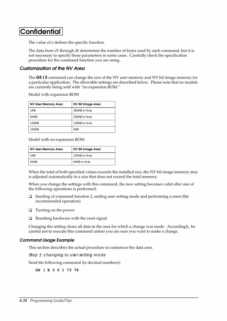
4-28 Programming Guide/Tips
ConfidentialThe value of a defines the specific function.
The data from d1 through dk determines the number of bytes used by each command, but it is not necessary to specify these parameters in some cases. Carefully check the specification procedure for the command function you are using.
Customization of the NV Area
The GS ( E command can change the size of the NV user memory and NV bit image memory for a particular application. The allowable settings are described below. Please note that no models are currently being sold with “no expansion ROM.”
Model with expansion ROM
Model with no expansion ROM
When the total of both specified values exceeds the installed size, the NV bit image memory area is adjusted automatically to a size that does not exceed the total memory.
When you change the settings with this command, the new setting becomes valid after one of the following operations is performed:
Sending of command function 2, ending user setting mode and performing a reset (the recommended operation).
Turning on the power
Resetting hardware with the reset signal
Changing the setting clears all data in the area for which a change was made. Accordingly, be careful not to execute this command unless you are sure you want to make a change.
Command Usage Example
This section describes the actual procedure to customize the data area.
Step 1: changing to user setting mode
Send the following command (in decimal numbers):
GS ( E 3 0 1 73 78
NV User Memory Area NV Bit Image Area
1KB 384KB or less
64KB 256KB or less
128KB 128KB or less
192KB 0KB
NV User Memory Area NV Bit Image Area
1KB 192KB or less
64KB 64KB or less
Programming Guide/Tips 4-29
TM-H6000/H6000P Developer’s GuideConfidentialAfter this command is sent, the printer returns data indicating that it has changed into the user setting mode. This confirmation consists of 3 bytes: header (37h) + identifier (20h) + NUL (00h). Be sure the printer has sent these three bytes to ensure the setting has been performed properly.
Step 2: customization of NV memory
This command allocates the NV memory. You can use the command below to expand the standard NV user memory from 1KB to 128KB. When you expand the NV user memory, the NV bit image memory is reduced to 128KB. Send the following command (in decimal numbers):
GS ( E 7 0 5 1 3 0 2 3 0
Step 3: end user setting mode
When you finish making the settings, end the user setting mode, and send the following command to activate the new settings (in decimal numbers):
GS ( E 4 0 2 79 85 84
The printer performs internal processing to activate the settings completed in the user mode. This consists of initialization of the memory. Data cannot be sent to the printer during this time.
You can also activate the settings by turning the power off and on again, or by resetting the hardware with the signal wire reset signal. However, unless there is a particular problem, end the mode by sending the command above.
Step 4: confirming setting
When the printer completes its internal processing, check to confirm that the settings have been activated. First, check the status of the NV user memory. Send the following command (in decimal numbers):
GS ( E 2 0 6 1
After the printer receives this command, it returns data indicating the NV user memory. The data is as follows: header (37h) + identifier (27h) + customizing value number + division code (1Fh) + customizing value + NUL (00h). In the example in “Step 2: customizing NV memory,” the area is 128KB. Therefore, the printer returns (31h) as the number of the memory area you are checking, and returns (33h) as the customized value of the memory area size.
Next, confirm the NV bit image memory status. Send the following command (in decimal numbers):
GS ( E 2 0 6 2
After the printer receives this command, it sends back data indicating the NV bit image memory. The data is as follows: header (37h) + identifier (27h) + customizing value number + division code (1Fh) + customizing value + NUL (00h). In this case, the area is 128KB. Therefore, the printer returns (32h) as the number of the memory area you are checking, and returns (33h) as the customized value of the memory area size.
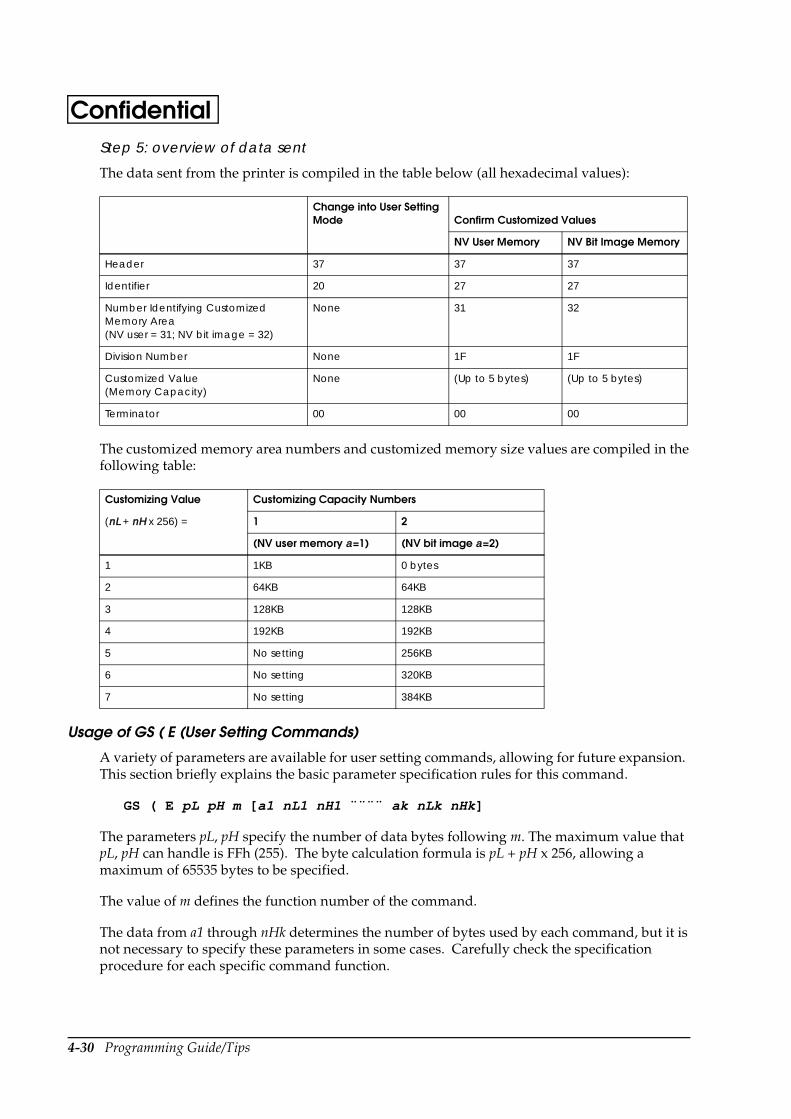
4-30 Programming Guide/Tips
ConfidentialStep 5: overview of data sent
The data sent from the printer is compiled in the table below (all hexadecimal values):
The customized memory area numbers and customized memory size values are compiled in the following table:
Usage of GS ( E (User Setting Commands)
A variety of parameters are available for user setting commands, allowing for future expansion. This section briefly explains the basic parameter specification rules for this command.
GS ( E pL pH m [ a1 nL1 nH1 ¨¨¨¨ ak nLk nHk]
The parameters pL, pH specify the number of data bytes following m. The maximum value that pL, pH can handle is FFh (255). The byte calculation formula is pL + pH x 256, allowing a maximum of 65535 bytes to be specified.
The value of m defines the function number of the command.
The data from a1 through nHk determines the number of bytes used by each command, but it is not necessary to specify these parameters in some cases. Carefully check the specification procedure for each specific command function.
Change into User Setting Mode Confirm Customized Values
NV User Memory NV Bit Image Memory
Header 37 37 37
Identifier 20 27 27
Number Identifying Customized Memory Area(NV user = 31; NV bit image = 32)
None 31 32
Division Number None 1F 1F
Customized Value (Memory Capacity)
None (Up to 5 bytes) (Up to 5 bytes)
Terminator 00 00 00
Customizing Value Customizing Capacity Numbers
(nL + nH x 256) = 1 2
(NV user memory a=1) (NV bit image a=2)
1 1KB 0 bytes
2 64KB 64KB
3 128KB 128KB
4 192KB 192KB
5 No setting 256KB
6 No setting 320KB
7 No setting 384KB
Programming Guide/Tips 4-31
TM-H6000/H6000P Developer’s GuideConfidentialNotes on Usage of Programming Language
Visual Basic®
When programming with Visual Basic, limitations prevent data from 81h through 9Fh and E0h through FEh from being sent as characters. However, you can use the following procedure to send this data:
Dim Send_data(0) As Byte
Send_data(0) = &h81 ’1 byte of sending data
MSComm1.Output = Send_data
Bit Image Out of Position
Programming Error
A bit image may print out of position when the actual quantity of data sent differs from the settings. Check the settings, referring to the calculation procedure for the specified bit image data.
Handshaking Error
The image also may print out of position if the handshake operation is not performed normally when a large bit image data record is sent. Confirm that the printer settings and program settings are correct.
Reducing Space Below Logo
Relationship of Print Head and Cutter Position
When the paper is cut on the 70th dot line immediately after completion of the previous printing operation, you can perform cutting at the end of the previous printing operation. This is possible because the thermal printing head is approximately 13 mm (0.5 in) away from the cutter position.
Space Between Characters
There are two types of dot impact characters: 5 x 9 dot characters, and 7 x 9 dot characters. These dot values do not include the space between characters. However, for actual printing (font configuration), the space between characters is included.
The font configuration for thermal characters includes a 2-dot space between characters. Furthermore, to set the amount of right space with the ESC/POS command, use the basic font + specified space value. As a rule, the space between characters cannot be set to 0, but the space between dots can be set to 0 with the ESC $ absolute position specification command.
4-32 Programming Guide/Tips
ConfidentialUsage of a Hex Dump
When It is Required
Use the hex dump function to check data sent from the host when printed results differ from the data entered or when characters are missing.
Procedure for Changing to Dump Mode
Panel operation
Open the paper roll cover, and turn the power off and then on again. Then close the cover.
Command
Send the GS ( A pL pH n m command. At this time, the following values are fixed: pL = 2, pH = 0, m = 1. When n = 0 - 2 or 48 - 50, printing is on the paper roll, and when n = 3 - 4 or 51 - 52, printing is on slip paper.
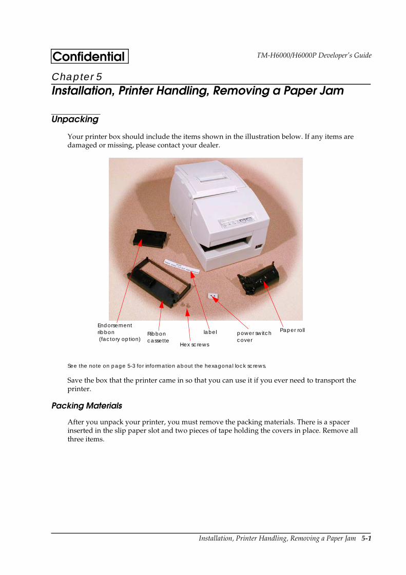
Installation, Printer Handling, Removing a Paper Jam 5-1
TM-H6000/H6000P Developer’s GuideConfidentialChapter 5 Installation, Printer Handling, Removing a Paper Jam
Unpacking
Your printer box should include the items shown in the illustration below. If any items are damaged or missing, please contact your dealer.
See the note on page 5-3 for information about the hexagonal lock screws.
Save the box that the printer came in so that you can use it if you ever need to transport the printer.
Packing Materials
After you unpack your printer, you must remove the packing materials. There is a spacer inserted in the slip paper slot and two pieces of tape holding the covers in place. Remove all three items.
Endorsement ribbon (factory option)
Paper roll
Hex screws
power switch cover
Ribbon cassette
label
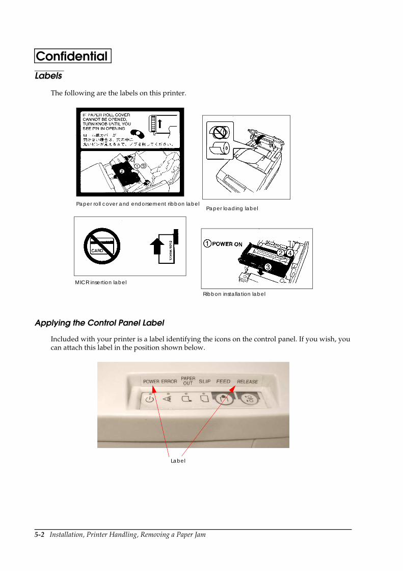
5-2 Installation, Printer Handling, Removing a Paper Jam
ConfidentialLabels
The following are the labels on this printer.
Applying the Control Panel Label
Included with your printer is a label identifying the icons on the control panel. If you wish, you can attach this label in the position shown below.
Paper roll cover and endorsement ribbon label
Ribbon installation label
Paper loading label
MICR insertion label
Label
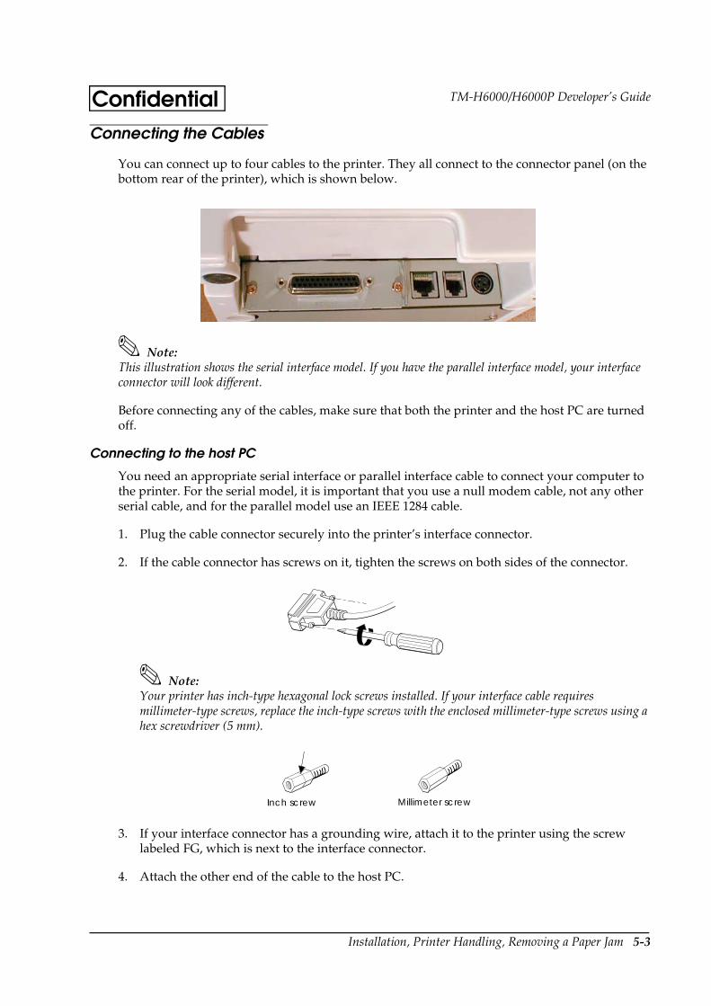
Installation, Printer Handling, Removing a Paper Jam 5-3
TM-H6000/H6000P Developer’s GuideConfidentialConnecting the Cables
You can connect up to four cables to the printer. They all connect to the connector panel (on the bottom rear of the printer), which is shown below.
Note:This illustration shows the serial interface model. If you have the parallel interface model, your interface connector will look different.
Before connecting any of the cables, make sure that both the printer and the host PC are turned off.
Connecting to the host PC
You need an appropriate serial interface or parallel interface cable to connect your computer to the printer. For the serial model, it is important that you use a null modem cable, not any other serial cable, and for the parallel model use an IEEE 1284 cable.
1. Plug the cable connector securely into the printer’s interface connector.
2. If the cable connector has screws on it, tighten the screws on both sides of the connector.
Note:Your printer has inch-type hexagonal lock screws installed. If your interface cable requires millimeter-type screws, replace the inch-type screws with the enclosed millimeter-type screws using a hex screwdriver (5 mm).
3. If your interface connector has a grounding wire, attach it to the printer using the screw labeled FG, which is next to the interface connector.
4. Attach the other end of the cable to the host PC.
Inch screw Millimeter screw
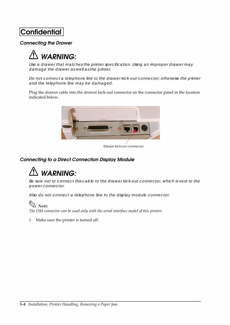
5-4 Installation, Printer Handling, Removing a Paper Jam
ConfidentialConnecting the Drawer
WARNING:Use a drawer that matches the printer specification. Using an improper drawer may damage the drawer as well as the printer.
Do not connect a telephone line to the drawer kick-out connector; otherwise the printer and the telephone line may be damaged.
Plug the drawer cable into the drawer kick-out connector on the connector panel in the location indicated below.
Connecting to a Direct Connection Display Module
WARNING:Be sure not to connect this cable to the drawer kick-out connector, which is next to the power connector.
Also do not connect a telephone line to the display module connector.
Note:The DM connector can be used only with the serial interface model of this printer.
1. Make sure the printer is turned off.
Drawer kick-out connector
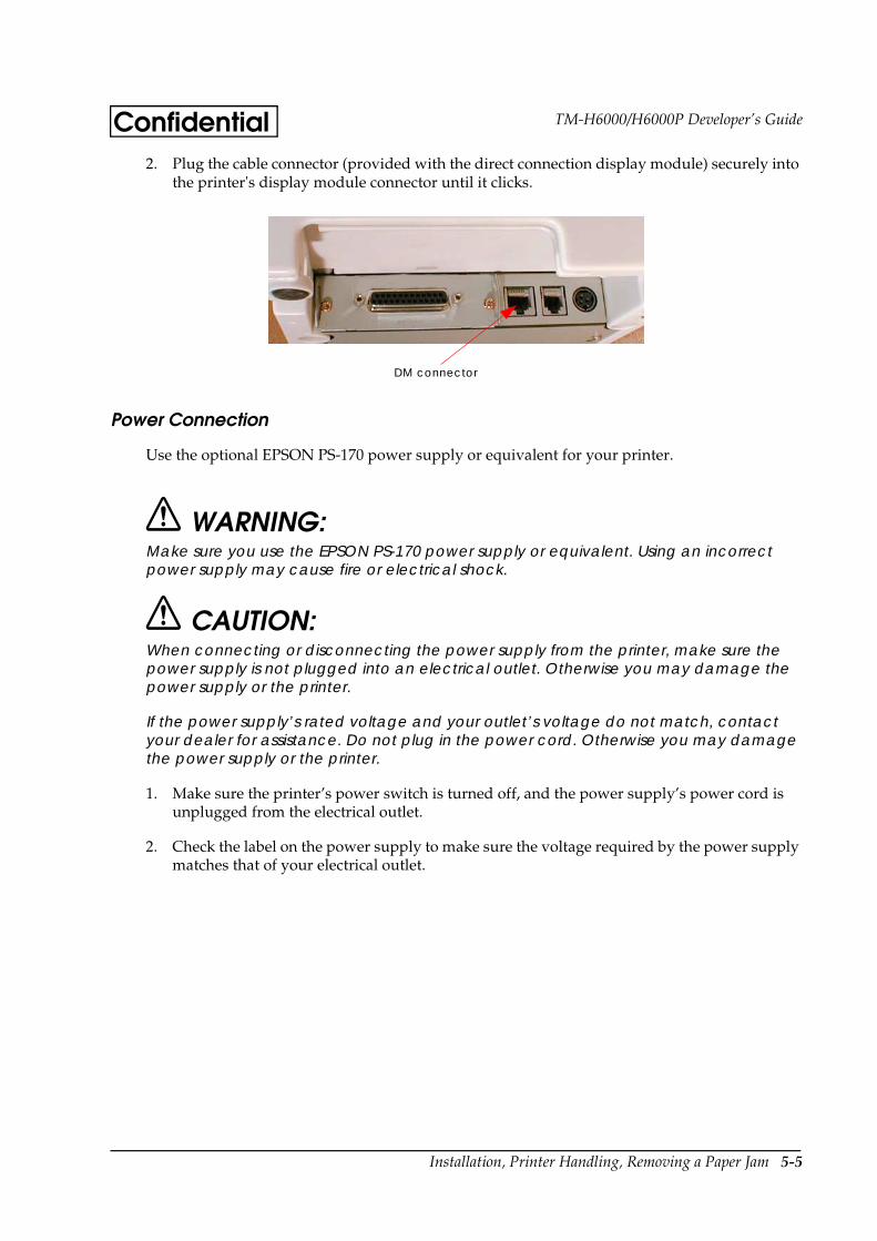
Installation, Printer Handling, Removing a Paper Jam 5-5
TM-H6000/H6000P Developer’s GuideConfidential2. Plug the cable connector (provided with the direct connection display module) securely into
the printer's display module connector until it clicks.
Power Connection
Use the optional EPSON PS-170 power supply or equivalent for your printer.
WARNING:Make sure you use the EPSON PS-170 power supply or equivalent. Using an incorrect power supply may cause fire or electrical shock.
CAUTION:When connecting or disconnecting the power supply from the printer, make sure the power supply is not plugged into an electrical outlet. Otherwise you may damage the power supply or the printer.
If the power supply’s rated voltage and your outlet’s voltage do not match, contact your dealer for assistance. Do not plug in the power cord. Otherwise you may damage the power supply or the printer.
1. Make sure the printer’s power switch is turned off, and the power supply’s power cord is unplugged from the electrical outlet.
2. Check the label on the power supply to make sure the voltage required by the power supply matches that of your electrical outlet.
DM connector
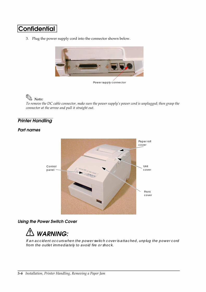
5-6 Installation, Printer Handling, Removing a Paper Jam
Confidential3. Plug the power supply cord into the connector shown below.
Note:To remove the DC cable connector, make sure the power supply’s power cord is unplugged; then grasp the connector at the arrow and pull it straight out.
Printer Handling
Part names
Using the Power Switch Cover
WARNING:If an accident occurs when the power switch cover is attached, unplug the power cord from the outlet immediately to avoid fire or shock.
Power supply connector
Front cover
Paper roll cover
Unit cover
Control panel

Installation, Printer Handling, Removing a Paper Jam 5-7
TM-H6000/H6000P Developer’s GuideConfidentialYou can use the enclosed power switch cover to make sure the power switch is not accidentally pressed. The illustration below shows the power switch cover installed.
If you need to turn the power on or off when the cover is installed, you can insert a thin tool into one of the holes in the cover to operate the switch.
Opening the Front Cover
You can open the front cover of the printer by using the tabs on each side of the cover.
Power switch cover
Tab

5-8 Installation, Printer Handling, Removing a Paper Jam
ConfidentialInstalling or Replacing the Paper Roll
Note:Do not use paper rolls that have the paper glued or taped to the core because they might cause a paper jam.
To prevent paper jams, make sure that nothing obstructs paper coming out of the paper exit, and do not pull the paper out of the printer.
1. To prevent data loss make sure that the printer is not receiving data.
2. Open the paper roll cover by lifting up the two tabs on the paper roll cover and then pushing the cover back.
3. Remove the used paper roll core if there is one.
4. Insert the paper roll as shown.
5. Be sure to note the correct direction that the paper should come off the roll.

Installation, Printer Handling, Removing a Paper Jam 5-9
TM-H6000/H6000P Developer’s GuideConfidential6. Pull out a small amount of paper, as shown. Then close the cover and tear off the extra paper
by pulling it toward the front of the printer.
Installing the Ribbon Cassette
EPSON recommends the use of genuine EPSON ribbon cassettes. Ribbon cassettes not manufactured by EPSON may cause damage to your printer that is not covered by EPSON’s warranties.
To install the ribbon cassette for the first time or to replace a used ribbon, follow the steps below:
Note:Be sure to turn on the power before installing a ribbon cassette.
1. Unpack the ribbon cassette and turn the knob in the direction shown to take up any slack.
Knob
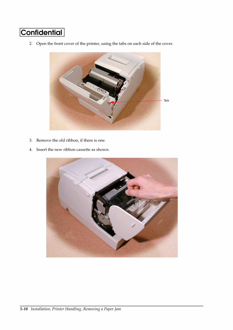
5-10 Installation, Printer Handling, Removing a Paper Jam
Confidential2. Open the front cover of the printer, using the tabs on each side of the cover.
3. Remove the old ribbon, if there is one.
4. Insert the new ribbon cassette as shown.
Tab
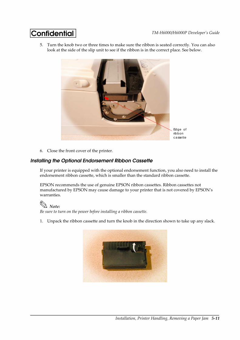
Installation, Printer Handling, Removing a Paper Jam 5-11
TM-H6000/H6000P Developer’s GuideConfidential5. Turn the knob two or three times to make sure the ribbon is seated correctly. You can also
look at the side of the slip unit to see if the ribbon is in the correct place. See below.
6. Close the front cover of the printer.
Installing the Optional Endorsement Ribbon Cassette
If your printer is equipped with the optional endorsement function, you also need to install the endorsement ribbon cassette, which is smaller than the standard ribbon cassette.
EPSON recommends the use of genuine EPSON ribbon cassettes. Ribbon cassettes not manufactured by EPSON may cause damage to your printer that is not covered by EPSON’s warranties.
Note:Be sure to turn on the power before installing a ribbon cassette.
1. Unpack the ribbon cassette and turn the knob in the direction shown to take up any slack.
Edge of ribbon cassette
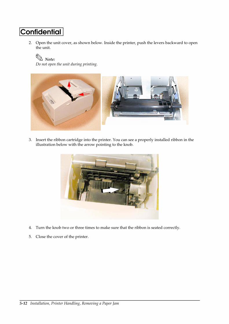
5-12 Installation, Printer Handling, Removing a Paper Jam
Confidential2. Open the unit cover, as shown below. Inside the printer, push the levers backward to open
the unit.
Note:Do not open the unit during printing.
3. Insert the ribbon cartridge into the printer. You can see a properly installed ribbon in the illustration below with the arrow pointing to the knob.
4. Turn the knob two or three times to make sure that the ribbon is seated correctly.
5. Close the cover of the printer.
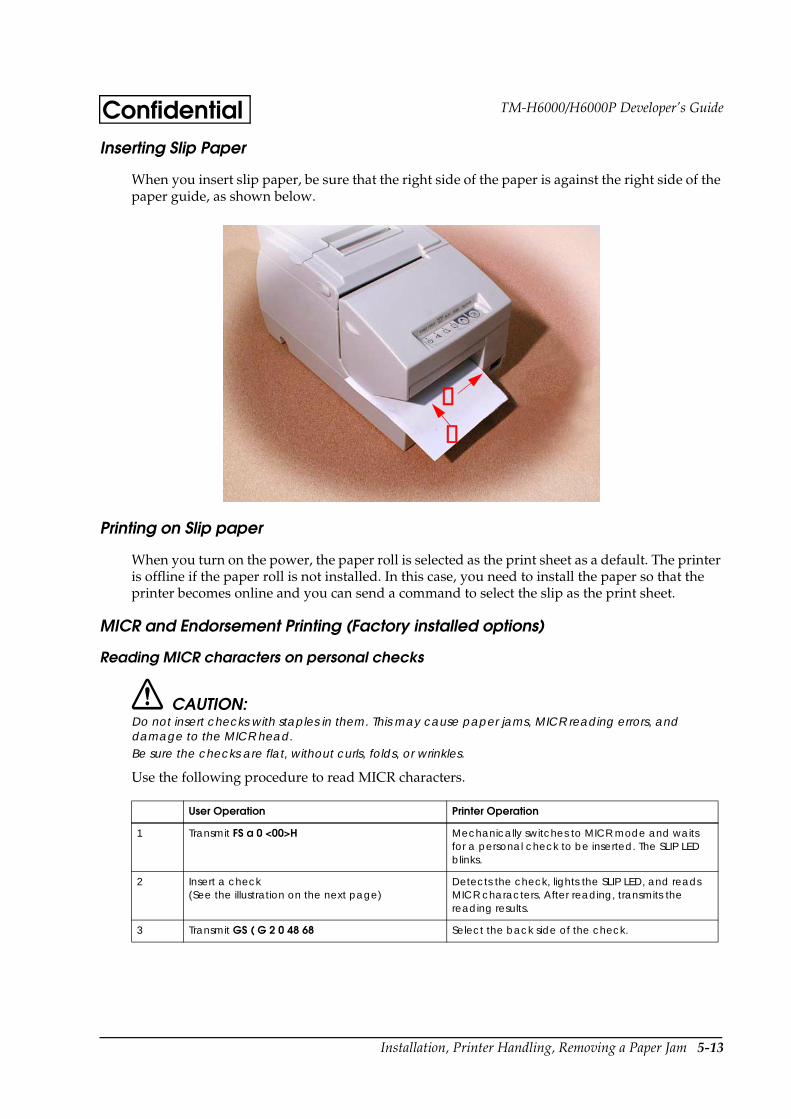
Installation, Printer Handling, Removing a Paper Jam 5-13
TM-H6000/H6000P Developer’s GuideConfidentialInserting Slip Paper
When you insert slip paper, be sure that the right side of the paper is against the right side of the paper guide, as shown below.
Printing on Slip paper
When you turn on the power, the paper roll is selected as the print sheet as a default. The printer is offline if the paper roll is not installed. In this case, you need to install the paper so that the printer becomes online and you can send a command to select the slip as the print sheet.
MICR and Endorsement Printing (Factory installed options)
Reading MICR characters on personal checks
CAUTION: Do not insert checks with staples in them. This may cause paper jams, MICR reading errors, and damage to the MICR head.Be sure the checks are flat, without curls, folds, or wrinkles.
Use the following procedure to read MICR characters.
User Operation Printer Operation
1 Transmit FS a 0 <00>H Mechanically switches to MICR mode and waits for a personal check to be inserted. The SLIP LED blinks.
2 Insert a check (See the illustration on the next page)
Detects the check, lights the SLIP LED, and reads MICR characters. After reading, transmits the reading results.
3 Transmit GS ( G 2 0 48 68 Select the back side of the check.
➀¡
➁
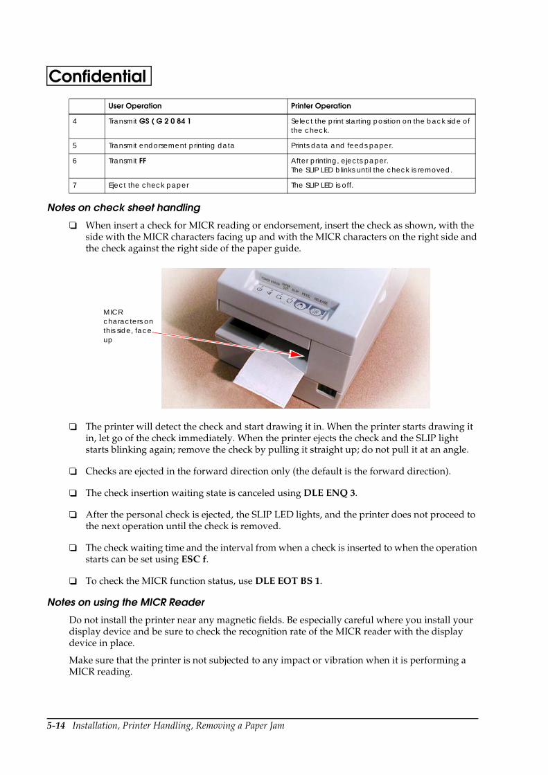
5-14 Installation, Printer Handling, Removing a Paper Jam
Confidential
Notes on check sheet handling
When insert a check for MICR reading or endorsement, insert the check as shown, with the side with the MICR characters facing up and with the MICR characters on the right side and the check against the right side of the paper guide.
The printer will detect the check and start drawing it in. When the printer starts drawing it in, let go of the check immediately. When the printer ejects the check and the SLIP light starts blinking again; remove the check by pulling it straight up; do not pull it at an angle.
Checks are ejected in the forward direction only (the default is the forward direction).
The check insertion waiting state is canceled using DLE ENQ 3.
After the personal check is ejected, the SLIP LED lights, and the printer does not proceed to the next operation until the check is removed.
The check waiting time and the interval from when a check is inserted to when the operation starts can be set using ESC f.
To check the MICR function status, use DLE EOT BS 1.
Notes on using the MICR Reader
Do not install the printer near any magnetic fields. Be especially careful where you install your display device and be sure to check the recognition rate of the MICR reader with the display device in place.
Make sure that the printer is not subjected to any impact or vibration when it is performing a MICR reading.
4 Transmit GS ( G 2 0 84 1 Select the print starting position on the back side of the check.
5 Transmit endorsement printing data Prints data and feeds paper.
6 Transmit FF After printing, ejects paper.The SLIP LED blinks until the check is removed.
7 Eject the check paper The SLIP LED is off.
User Operation Printer Operation
MICR characters on this side, face up
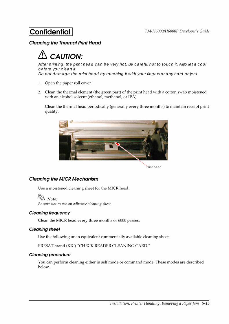
Installation, Printer Handling, Removing a Paper Jam 5-15
TM-H6000/H6000P Developer’s GuideConfidentialCleaning the Thermal Print Head
CAUTION:After printing, the print head can be very hot. Be careful not to touch it. Also let it cool before you clean it.Do not damage the print head by touching it with your fingers or any hard object.
1. Open the paper roll cover.
2. Clean the thermal element (the green part) of the print head with a cotton swab moistened with an alcohol solvent (ethanol, methanol, or IPA)
Clean the thermal head periodically (generally every three months) to maintain receipt print quality.
.
Cleaning the MICR Mechanism
Use a moistened cleaning sheet for the MICR head.
Note:Be sure not to use an adhesive cleaning sheet.
Cleaning frequency
Clean the MICR head every three months or 6000 passes.
Cleaning sheet
Use the following or an equivalent commercially available cleaning sheet:
PRESAT brand (KIC) “CHECK READER CLEANING CARD.”
Cleaning procedure
You can perform cleaning either in self mode or command mode. These modes are described below.
Print head
5-16 Installation, Printer Handling, Removing a Paper Jam
ConfidentialSelf mode
1. Load a paper roll in the printer.
2. Turn off the power.
3. Open the paper roll cover.
4. Turn the power back on while holding down the RELEASE button.
5. Press the RELEASE button seven times.
6. Close the paper roll cover.
7. The printer prints the following message on receipt paper and the SLIP light flashes.
8. Load the cleaning sheet like a standard check.
CAUTION:Be sure that the sheet is inserted with the correct side up and that it is inserted in the correct direction.
9. When the sheet is ejected, press the RELEASE button, and remove the sheet from the printer.
CAUTION:Do not use a cleaning sheet more than once.
Command mode
1. Send the FS c cleaning command to the printer.
2. Perform steps 8 and 9, as described in self mode.
Removing a Paper Jam
CAUTION:Do not touch the paper feed motor because it can be very hot.
If the paper is jammed in the paper roll section, turn the printer off. Next, open the paper roll cover. Then remove the jammed paper and put the roll back in the printer and close the cover.

Installation, Printer Handling, Removing a Paper Jam 5-17
TM-H6000/H6000P Developer’s GuideConfidentialIf the paper is jammed in the slip section, turn off the printer and remove the jammed paper and use a fresh sheet. If you cannot remove the jammed paper easily, open the unit cover. Move the tabs on the sides of the cover forward and then lift the cover, as shown below.
Push the levers backward to open the unit as shown below, and then remove the jammed paper.
If the paper roll cover cannot be opened because paper is caught in the autocutter in the receipt section, follow the instructions in the autocutter section below.
Autocutter Jam
If a foreign object such as a push pin or paper clip drops in the autocutter and causes the auto cutter to lock up, the printer enters an error state and begins the recovery operation automatically.
If the problem is not serious, the autocutter returns to its normal position without any intervention by the user.
If the autocutter does not return to its normal position by itself, follow the steps below to correct the problem:
Tab
LeverLever
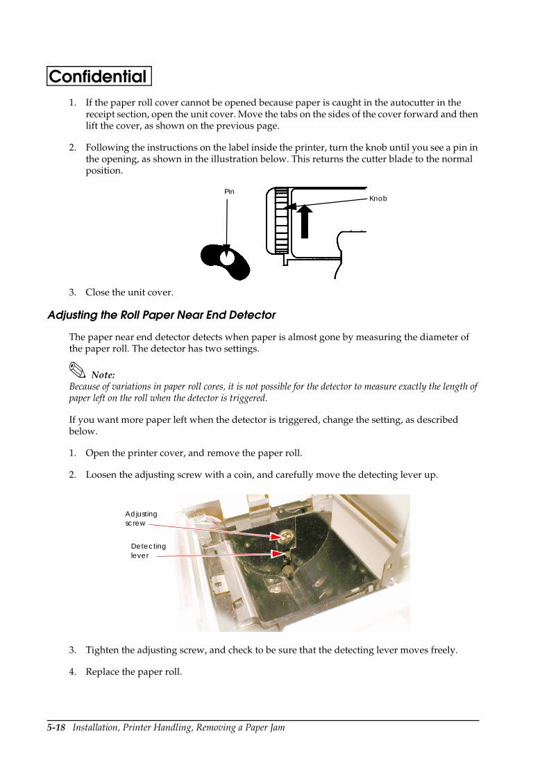
5-18 Installation, Printer Handling, Removing a Paper Jam
Confidential1. If the paper roll cover cannot be opened because paper is caught in the autocutter in the
receipt section, open the unit cover. Move the tabs on the sides of the cover forward and then lift the cover, as shown on the previous page.
2. Following the instructions on the label inside the printer, turn the knob until you see a pin in the opening, as shown in the illustration below. This returns the cutter blade to the normal position.
3. Close the unit cover.
Adjusting the Roll Paper Near End Detector
The paper near end detector detects when paper is almost gone by measuring the diameter of the paper roll. The detector has two settings.
Note:Because of variations in paper roll cores, it is not possible for the detector to measure exactly the length of paper left on the roll when the detector is triggered.
If you want more paper left when the detector is triggered, change the setting, as described below.
1. Open the printer cover, and remove the paper roll.
2. Loosen the adjusting screw with a coin, and carefully move the detecting lever up.
3. Tighten the adjusting screw, and check to be sure that the detecting lever moves freely.
4. Replace the paper roll.
Pin Knob
Adjusting screw
Detecting lever

Character Code Tables Appendix A-1
TM-H6000/H6000P Developer’s GuideConfidentialAppendix A Character Code Tables
Page 0 (PC437: USA, Standard Europe) (International Character Set: USA)
NOTE: Character code tables show only character configurations, not the actual print pattern.
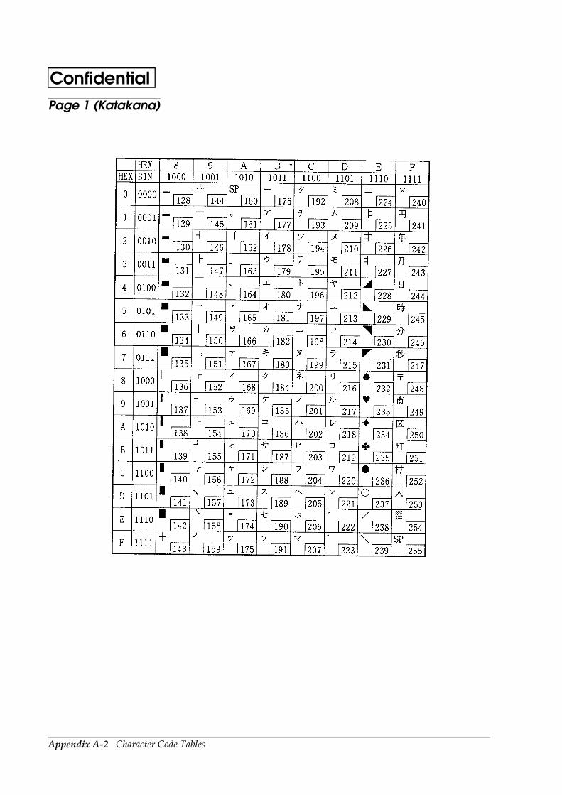
Appendix A-2 Character Code Tables
ConfidentialPage 1 (Katakana)
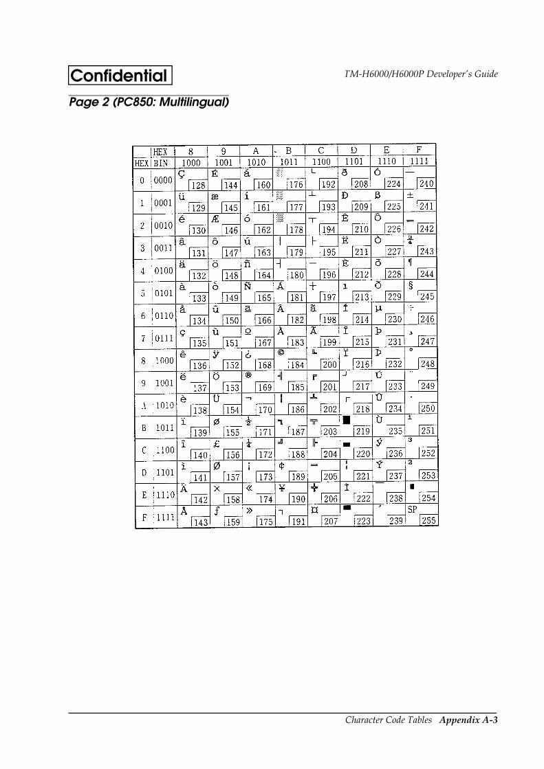
Character Code Tables Appendix A-3
TM-H6000/H6000P Developer’s GuideConfidentialPage 2 (PC850: Multilingual)

Appendix A-4 Character Code Tables
ConfidentialPage 3 (PC860: Portuguese)

Character Code Tables Appendix A-5
TM-H6000/H6000P Developer’s GuideConfidentialPage 4 (PC863: Canadian-French)
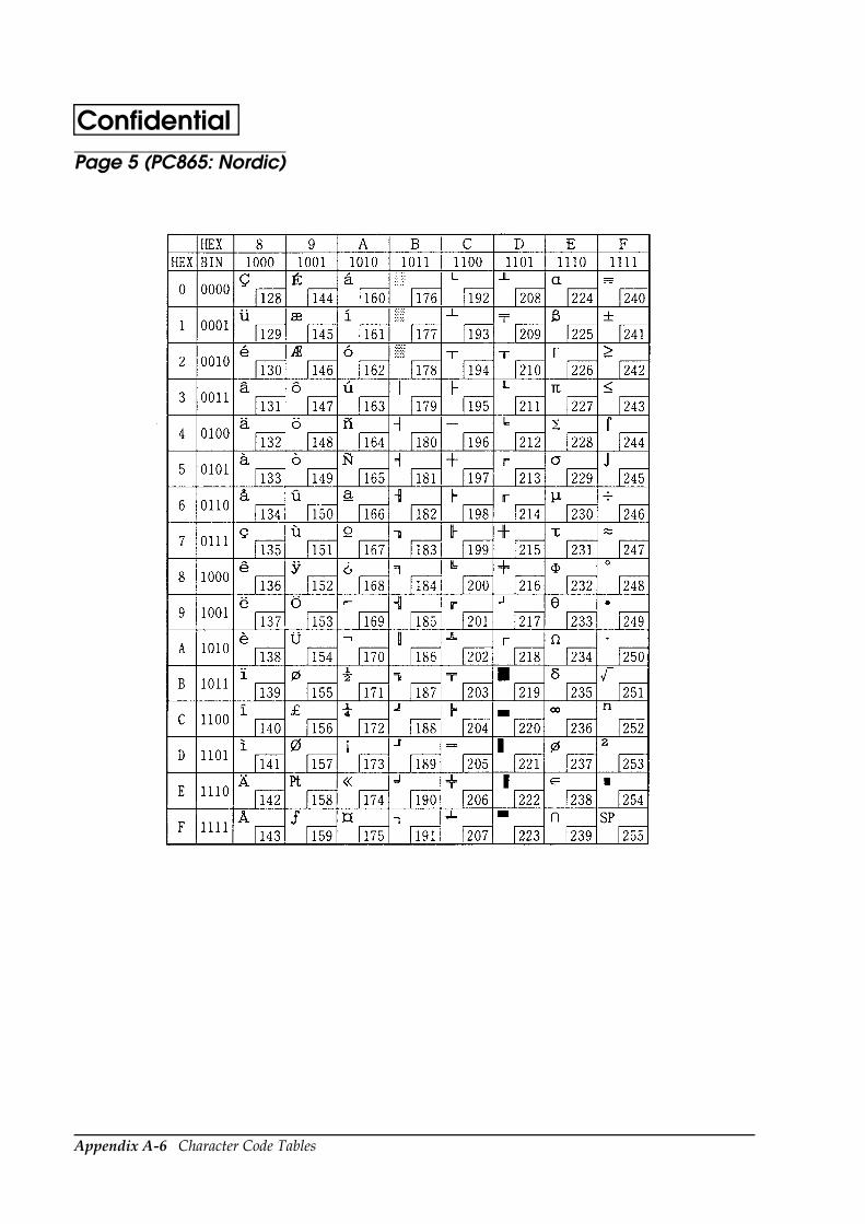
Appendix A-6 Character Code Tables
ConfidentialPage 5 (PC865: Nordic)

Character Code Tables Appendix A-7
TM-H6000/H6000P Developer’s GuideConfidentialPage 16 (WPC1252)

Appendix A-8 Character Code Tables
ConfidentialPage 17 (PC866: Cyrillic2)
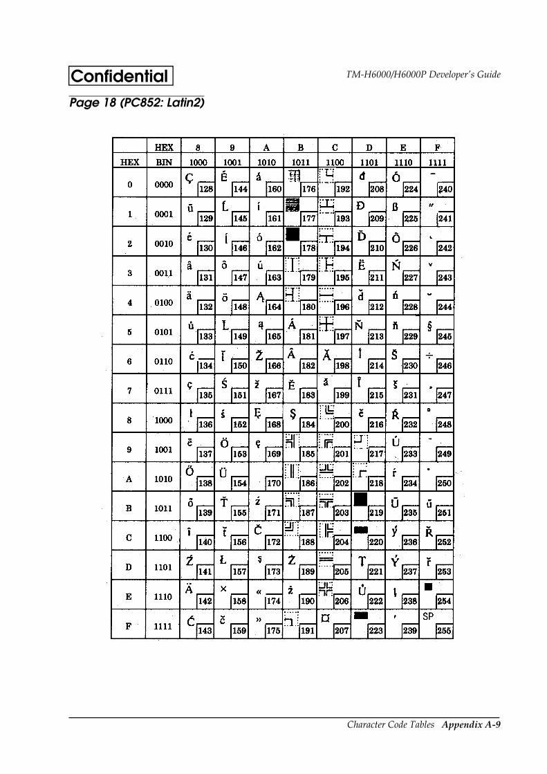
Character Code Tables Appendix A-9
TM-H6000/H6000P Developer’s GuideConfidentialPage 18 (PC852: Latin2)
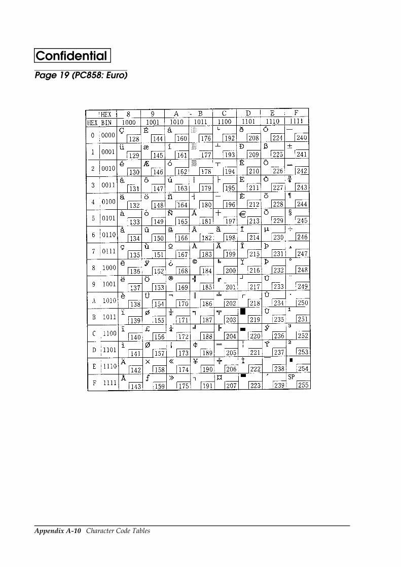
Appendix A-10 Character Code Tables
ConfidentialPage 19 (PC858: Euro)
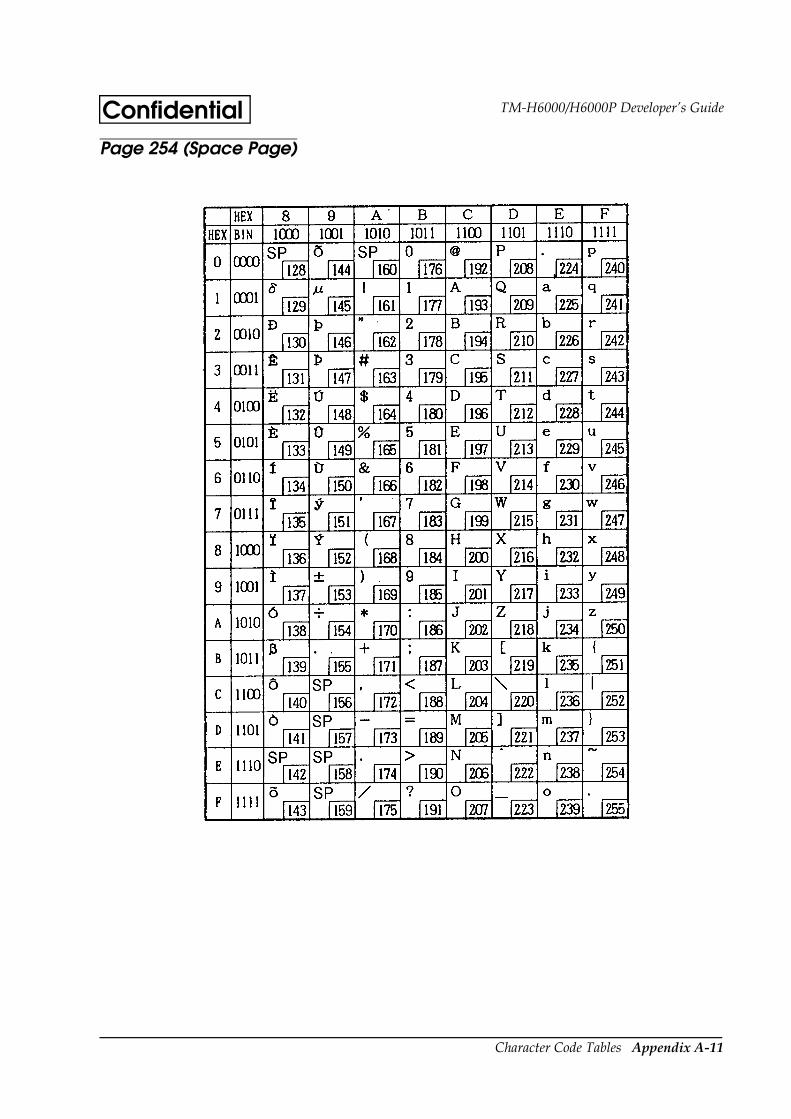
Character Code Tables Appendix A-11
TM-H6000/H6000P Developer’s GuideConfidentialPage 254 (Space Page)
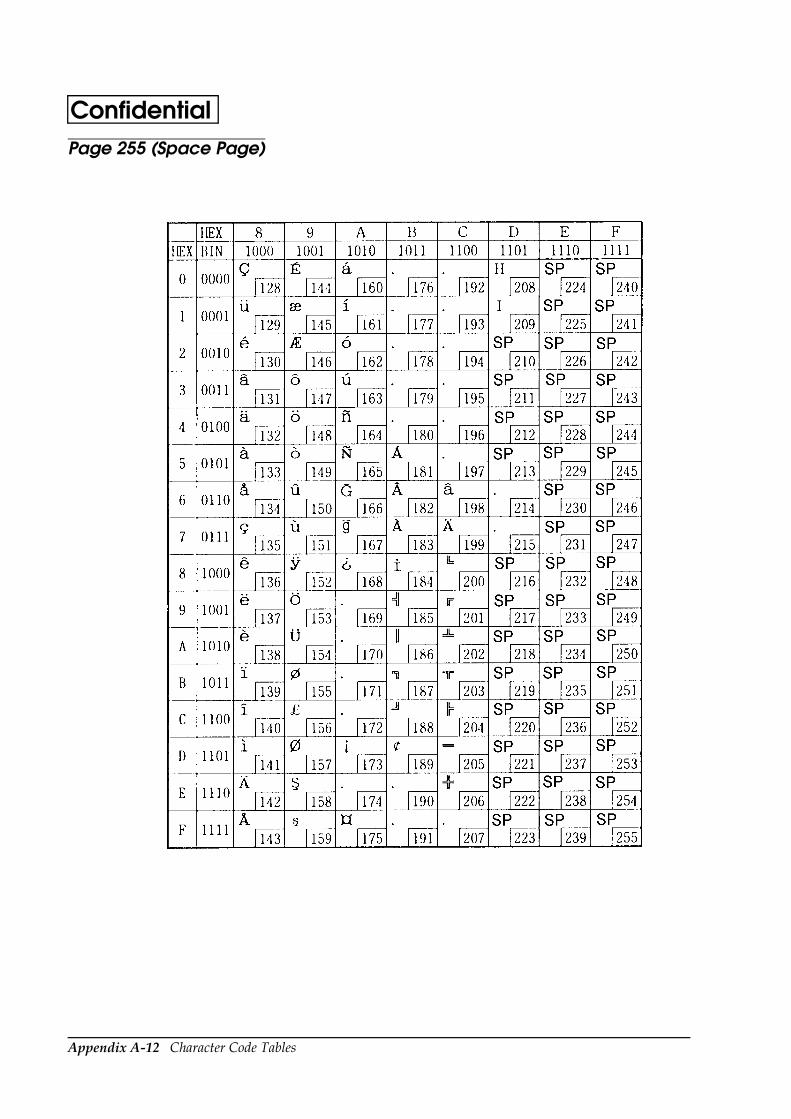
Appendix A-12 Character Code Tables
ConfidentialPage 255 (Space Page)

Character Code Tables Appendix A-13
TM-H6000/H6000P Developer’s GuideConfidentialInternational Character Sets
ASCII code (Hex)
Country 23 24 40 5B 5C 5D 5E 60 7B 7C 7D 7E
U.S.A # $ @ [ \ ] ^ ` | ~
France # $ à ° ç § ^ ` é ù è ¨
Germany # $ § Ä Ö Ü ^ ` ä ö ü ß
U.K. £ $ @ [ \ ] ^ ` | ~
Denmark I # $ @ Æ Ø Å ^ ` æ ø å ~
Sweden # ¤ É Ä Ö Å Ü é ä ö å ü
Italy # $ @ ° \ é ^ ù à ò è ì
Spain I Pt $ @ ¡ Ñ ¿ ^ ` ¨ ñ ~
Japan # $ @ [ ¥ ] ^ ` | ~
Norway # ¤ É Æ Ø Å Ü é æ ø å ü
Denmark II # $ É Æ Ø Å Ü é æ ø å ü
Spain II # $ á ¡ Ñ ¿ é ` í ñ ó ú
Latin America # $ á ¡ Ñ ¿ é ü í ñ ó ú
Korea # $ @ [ W ] ^ ` | ~

Appendix A-14 Character Code Tables
Confidential
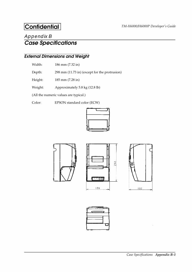
Case Specifications Appendix B-1
TM-H6000/H6000P Developer’s GuideConfidentialAppendix B Case Specifications
External Dimensions and Weight
Width: 186 mm (7.32 in)
Depth: 298 mm (11.73 in) (except for the protrusion)
Height: 185 mm (7.28 in)
Weight: Approximately 5.8 kg (12.8 lb)
(All the numeric values are typical.)
Color: EPSON standard color (ECW)

Appendix B-2 Case Specifications
Confidential
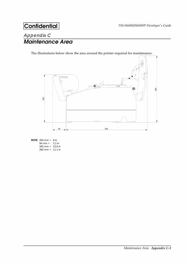
Maintenance Area Appendix C-1
TM-H6000/H6000P Developer’s GuideConfidentialAppendix C Maintenance Area
The illustrations below show the area around the printer required for maintenance.
NOTE: 203 mm = 8 in56 mm = 2.2 in345 mm = 13.6 in282 mm = 11.1 in
203
56 345
282

Appendix C-2 Maintenance Area
Confidential
Definitions Appendix D-1
TM-H6000/H6000P Developer’s GuideConfidentialAppendix D Definitions
A
ASB — Auto status back: a feature that allows the printer to send status information back to the host comuter.
autocutter — Optional printer device that automatically cuts the receipt for the current transaction from the paper roll.
B
bidirectional —Two-way communication between the host and printer, which allows the printer to return status information to the host. The IEEE 1284 standard for the parallel interface used in the TM-H6000 has the capacity for bidirectional communication.
bitmap — A graphic or a character comprised of individual pixels or dots (as opposed to a vector or scalable image, created with mathematical algorithms).
black mark — A positioning mark printed on slips, such as ATM receipts.
BOF — Bottom of form: the vertical point on the paper at which the printer skips to the top of the next form. (Or, the point on the sheet where the bottom margin begins.) The TM-H6000 has a BOF sensor for slip paper.
buffer — A memory area in the printer that holds incoming data until it is processed. In the TM-H6000, there is a receive buffer (DIP switch selectable as 45 bytes or 45KB), a user-defined buffer (12KB for receipts and 3KB for slips), an NV bit image buffer (384KB, default), and an NV user memory buffer (1KB).
C
carbonless paper —A type of copy paper for impact printers. When a pin fires and strikes the ribbon against the top sheet, the pressure causes a chemical interaction between the top sheet and the sheets below, creating a corresponding dot on those sheets also.
confidentiality —The agreement required for anyone to use this document.
CPL — Characters per line.

Appendix D-2 Definitions
ConfidentialE
endorsement print mechanism —An optional, factory-installed shuttle printer mechanism for the TM-H6000 that allows it to print an endorsement automatically as the check is processed. This device is abbreviated as “E/P.”
ESC/POS — EPSON’s standard command language for POS devices.
F
font A — The default font. In the TM-H6000 receipt printer, font A uses 12 x 24 dot characters (including 2 dots of horizontal spacing); in the slip printer, font A uses 5 x 9 dot characters (including one dot of horizontal spacing).
font B — In the TM-H6000 receipt printer, font B uses 9 x 17 dot characters (including 2 dots of horizontal spacing); in the slip printer, font B uses 7 x 9 dot characters (including 2 half dots of horizontal spacing).
H
hex dump — A test mode in which the printer prints hexadecimal numbers representing characters and codes. Run a hex dump by opening the cover and turning on power while holding down the FEED button and then closing the cover.
I
IEEE 1284 — The standard used for the TM-H6000 parallel interface. This type of interface allows both bidirectional communications and unidirectional (“compatibility mode”) communications.
J
JavaPOS — A vendor-independent standard for using Sun Microsystems’ Java programming commands to support POS devices. (Compare with OPOS.)
L
LPS — Lines per second.
M
MICR — Magnetic ink character recognition. A MICR reader can recognize the type of ink found at the bottom of checks and deposit slips.

Definitions Appendix D-3
TM-H6000/H6000P Developer’s GuideConfidentialMSR — Magnetic stripe reader. Magnetic stripes are found on the back of credit cards.
N
null modem cable —A type of serial cable wired so that the send data (SD) line from the host goes to the receive data (RD) pin of the printer connector, and the send data (SD) signal from the printer returns to the receive data (RD) pin of the host’s serial connector. It is also called a “cross cable.” This type of cable is required for serial communications between a host and printer. (Communications from a host to a modem use a straight-through cable.)
NV — Non-volatile. The data in this type of memory is not lost when power is turned off.
O
OLE POS — Also called OPOS. A standard using Microsoft’s OLE technology to support POS devices in a Windows environment.
P
page mode — In this mode, the printer collects data and formatting commands in its buffer until printing is specified with the ESC FF or FF command. (See standard mode for reference.) This mode gives the printer more flexibility in formatting, so that it can print character data and bar code data or other graphics data on the same line. Printer values can be stored separately in page mode and standard mode.
partial cut — This type of cut made by the autocutter leaves one small segment of the receipt uncut.
R
ribbon — The TM-H6000 slip printer uses an ERC-32 (P) ribbon; the TM-H6000 endorsement printer uses an ERC-41 (P) ribbon.
RS-232C — The standard serial interface available for this printer.
RS-485 — A serial interface type available as a dealer option.
S
single-pass processing —The technology used in this printer to eliminate the need to turn a check over to print an endorsement.

Appendix D-4 Definitions
Confidentialstandard mode —
In this mode, the printer acts on print and command data as it is received from the host. (See page mode for reference.) Printer values can be stored separately in page mode and standard mode.
T
Thermal printer —A thermal printer uses heat elements to create dots on heat-sensitive paper.
Thermal paper —Heat-sensitive paper specially developed for thermal printers. Use only the thermal paper specified in TM-H6000 documentation.
TOF — Top of form: the point on the page at which the printer begins printing the top line of text or graphics. (Or, the beginning of the printable area, immediately below the top margin.) The TM-H6000 has a TOF sensor for slip paper.
U
USB — Universal Serial Bus. A serial interface that allows you to add peripheral devices dynamically on a single bus.
V
VAR — Value added reseller.

Confidential
EPSONSEIKO EPSON CORPORATION Printed in Japan