Embed Size (px)
Citation preview

TECHNICALPROCEDURESTEERABLE SUSPENSION SYSTEMSUBJECT: Installation and Preventative
Maintenance ProceduresLIT NO: H633DATE: May 2011 REVISION: E
SCR13SCT10
TABLE OF CONTENTSIntroduction . . . . . . . . . . . . . . . . . . . . . . . . . . . .2Special Notes . . . . . . . . . . . . . . . . . . . . . . . . . . .2Required Equipment and Materials for Installation .3Installation Instructions . . . . . . . . . . . . . . . . . . . .4
Safety . . . . . . . . . . . . . . . . . . . . . . . . . . . . .4Lifting . . . . . . . . . . . . . . . . . . . . . . . . . . . . .4Parts Handling . . . . . . . . . . . . . . . . . . . . . . .4Unpack Axle . . . . . . . . . . . . . . . . . . . . . . . . .4
Pre-lnstallation Checklist and Procedures . . . . . . .4Prior to Installation . . . . . . . . . . . . . . . . . . . . . . .5
Axle Identification . . . . . . . . . . . . . . . . . . . . .5Suspension Adjustability . . . . . . . . . . . . . . . .5Adjustable Ride Height . . . . . . . . . . . . . . . . .5Ride Height Spacer Installation . . . . . . . . . . . .5Adjustable Frame Width . . . . . . . . . . . . . . . .5Frame Width Adjustment Procedures . . . . . . .6
Suspension Mounting Installation Procedures . . . .6Suspension Frame Rail Installation . . . . . . . . . . . .7Upper Air Spring Plate Assembly and Air SpringInstallation . . . . . . . . . . . . . . . . . . . . . . . . . . . .8Axle Adjustments . . . . . . . . . . . . . . . . . . . . . . . .9
Toe Setting . . . . . . . . . . . . . . . . . . . . . . . . . .9Turn Angle Mechanical Stop . . . . . . . . . . . . . . . .9Options . . . . . . . . . . . . . . . . . . . . . . . . . . . . . . .9
Axle Controls . . . . . . . . . . . . . . . . . . . . . . . .9Lock Straight . . . . . . . . . . . . . . . . . . . . . . . .9
Manual and Automatic Lift . . . . . . . . . . . . . . .9Final Assembly . . . . . . . . . . . . . . . . . . . . . . . . .9Final Inspection . . . . . . . . . . . . . . . . . . . . . . . .10Preventative Maintenance . . . . . . . . . . . . . . . . .10
Kingpin Lubrication . . . . . . . . . . . . . . . . . .10Kingpin Bushing Inspection . . . . . . . . . . . . . . . .11
Inspection Procedure . . . . . . . . . . . . . . . . .11Checking the Upper Kingpin Bushing . . . . . .11Checking the Lower Kingpin Bushing . . . . . .12
Steering Knuckle Inspection and Adjustment . . . .12Checking Vertical End Play . . . . . . . . . . . . .12Adjusting Vertical End Play . . . . . . . . . . . . .12
Steering Knuckle Disassembly . . . . . . . . . . . . . .13Kingpin Preparation and Measurement . . . . . . . .13Fabricated Knuckle Kingpin Bushing Installation .14Lift Axle (LA) and Compliant Tie Rod (CTR) LiftBeam Urethane Bushings . . . . . . . . . . . . . . . . .15Pre SC Round Tube Tie Rod Adjustment . . . . . . .15Cast Knuckle Kingpin Bushing Removal . . . . . . .16Cast Steering Knuckle Bore Measurement . . . . . .16Kingpin Bushing Installation . . . . . . . . . . . . . . .17Kingpin Bushing Reaming . . . . . . . . . . . . . . . . .17Kingpin Seal Installation . . . . . . . . . . . . . . . . . .19Steering Knuckle Assembly . . . . . . . . . . . . . . . .19Appendix A . . . . . . . . . . . . . . . . . . . . . . . . . . .22Appendix B . . . . . . . . . . . . . . . . . . . . . . . . . . .23
SCT20
SCO13 / 20SCT13
STEERABLE INSTALLATION AND MAINTENANCE PROCEDURES
2H633 E
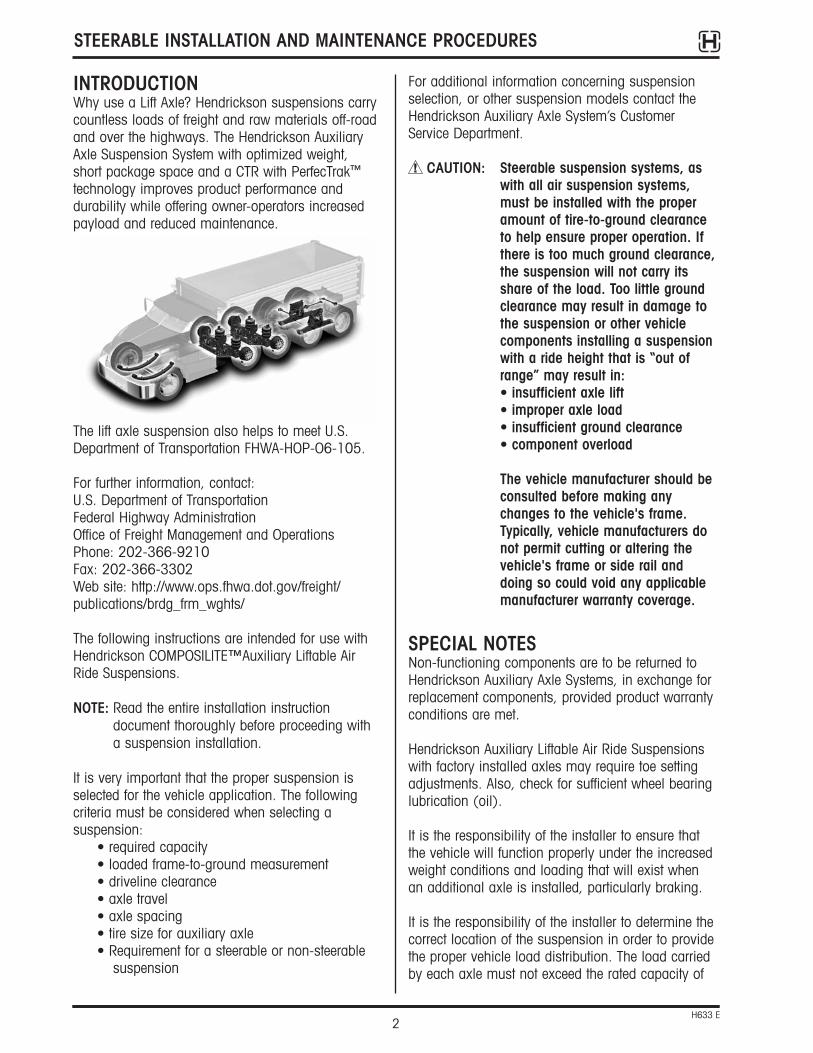
INTRODUCTIONWhy use a Lift Axle? Hendrickson suspensions carrycountless loads of freight and raw materials off-roadand over the highways. The Hendrickson AuxiliaryAxle Suspension System with optimized weight, short package space and a CTR with PerfecTrak™
technology improves product performance and durability while offering owner-operators increasedpayload and reduced maintenance.
The lift axle suspension also helps to meet U.S.Department of Transportation FHWA-HOP-O6-105.
For further information, contact:U.S. Department of TransportationFederal Highway AdministrationOffice of Freight Management and OperationsPhone: 202-366-9210Fax: 202-366-3302Web site: http://www.ops.fhwa.dot.gov/freight/publications/brdg_frm_wghts/
The following instructions are intended for use withHendrickson COMPOSILITE™Auxiliary Liftable AirRide Suspensions.
NOTE: Read the entire installation instructiondocument thoroughly before proceeding witha suspension installation.
It is very important that the proper suspension isselected for the vehicle application. The following criteria must be considered when selecting a suspension:
• required capacity• loaded frame-to-ground measurement• driveline clearance• axle travel• axle spacing• tire size for auxiliary axle• Requirement for a steerable or non-steerable
suspension
For additional information concerning suspensionselection, or other suspension models contact theHendrickson Auxiliary Axle System’s CustomerService Department.
CAUTION: Steerable suspension systems, aswith all air suspension systems,must be installed with the properamount of tire-to-ground clearanceto help ensure proper operation. Ifthere is too much ground clearance,the suspension will not carry itsshare of the load. Too little groundclearance may result in damage tothe suspension or other vehiclecomponents installing a suspensionwith a ride height that is “out ofrange” may result in:• insufficient axle lift• improper axle load• insufficient ground clearance• component overload
The vehicle manufacturer should beconsulted before making anychanges to the vehicle's frame.Typically, vehicle manufacturers donot permit cutting or altering thevehicle's frame or side rail anddoing so could void any applicablemanufacturer warranty coverage.
SPECIAL NOTESNon-functioning components are to be returned toHendrickson Auxiliary Axle Systems, in exchange forreplacement components, provided product warrantyconditions are met.
Hendrickson Auxiliary Liftable Air Ride Suspensionswith factory installed axles may require toe settingadjustments. Also, check for sufficient wheel bearinglubrication (oil).
It is the responsibility of the installer to ensure thatthe vehicle will function properly under the increasedweight conditions and loading that will exist whenan additional axle is installed, particularly braking.
It is the responsibility of the installer to determine thecorrect location of the suspension in order to providethe proper vehicle load distribution. The load carriedby each axle must not exceed the rated capacity of
STEERABLE INSTALLATION AND MAINTENANCE PROCEDURES
3H633 E
the components involved or the applicable State andFederal laws where the truck is to be operated.
It is the installer’s responsibility to ensure that properclearances exist:
• Between the drive shaft and/or roll-off cylinderand the auxiliary axle (if applicable)
• Around the tires—laterally, fore, aft, andvertically
• Around the air springs when they are at theirmaximum diameter (refer to suspensionassembly drawing for specifications)
• Around any moving suspension components
No welding to any of the suspension components ispermitted, except where specified by HendricksonAuxiliary Axle Systems.
No alteration of any of the suspension componentsis permitted.
Any installation deviations must be approved, inwriting, by Hendrickson Auxiliary Axle SystemsProduct Engineering Department. Failure to complywith these installation instructions without writtenpermission will void the suspension warranty.
CAUTION: Subjecting aluminum components tocertain acid washes may result inpremature corrosion and warrantycould be affected. It isrecommended that you monitorwhich cleaning solvents are beingused on your vehicle.
CAUTION: Acid washes also degrade therubber, urethane and plastic parts orthe axle assembly.
REQUIRED EQUIPMENT ANDMATERIALS FOR INSTALLATIONThe following equipment and materials are neededwhen installing a Hendrickson Steerable AuxiliaryLiftable Air Ride Suspension:
1. Frame Fasteners: 5/8-11 x 2 1/4" long grade 8 flange bolts and 5/8 IFI Grade C prevailingtorque flange nuts and the corresponding framedrill bit.
2. Torque wrench (capability of 450 ft. Ibs . forframe bolt installation).
3. Tape measure or scale(s) and machinistsquare.
4. Trammel bar.
5. Crane or other lifting device.
6. Hammer and center punch.
7. Compressed air supply.
8. Air impact gun.
9. Air fittings, tubing and associated tools.
10. Socket set and wrenches, including thefollowing sizes:
• 3/8"• 9/16"• 3/4"• 15/16"• 1-1/8"• 1-1/4" deep well socket
11. C-clamps or bar clamps with the minimumopening equal to the vehicle frame height.
12. Suspension assembly drawing supplied byHendrickson. Plumbing schematics supplied for pre-plumb suspensions only.
13. Angle measuring instrument (magneticprotractor) for self-steer axle.
14. Wheel chocks.
15. Frame jacks or supports.

STEERABLE INSTALLATION AND MAINTENANCE PROCEDURES
4H633 E
a. Verify that the axle spacing conforms toFederal and local bridge laws.
b. Verify that the auxiliary suspension location isbased on: front axle steer angle, vehiclewheel-base and maximum recommendedauxiliary axle spacing.
c. Verify that the vehicle will have the properload distribution after installation.
d. Verify that there is sufficient fore/aft frame railclearance to mount the auxiliarysuspension(s).
4. On truck frames:
a. Verify that the frame width is within theallowable mounting range of the suspension(refer to the suspension assembly drawing).
b. Mark the location of the suspension side railson the frame rails. (Refer to the suspensionassembly drawing) Check for interferenceswith any existing bracketry or mounting bolts.
c. Check for any interferences between the axleand the drive shaft, if applicable (refer to thesuspension assembly drawing).
d. Verify that the vehicle crossmembers andbacking plates are correctly positioned forproper support of the suspension.
WARNING: ADEQUATE SUSPENSION SUPPORTMUST BE PROVIDED WITHIN THEVEHICLE FRAME! A CROSSMEMBERMUST BE LOCATED 12" FORE ORAFT OF THE SIDE RAIL PIVOT BOLTCENTERLINE. FAILURE TO PROVIDEADEQUATE SUSPENSION SUPPORTCOULD RESULT IN SUSPENSIONDAMAGE AND/OR DAMAGE TO THEVEHICLE FRAME. (SEE FIGURE 1)
5. Confirm that the components listed on thesuspension assembly drawing have beenprovided in sufficient quantities. Contact theHendrickson Auxiliary Axle Customer ServiceDepartment if any components are missing ordamaged.
INSTALLATION INSTRUCTIONSSAFETY FIRSTBe sure to read and follow all installation and maintenance procedures.
LIFTINGPractice safe lifting procedures. Consider size, shapeand weight of assemblies. Obtain help or the assistance of a crane or lift truck when lifting heavyassemblies. Make sure the path of travel is clear.
PARTS HANDLINGWhen handling parts, be sure to wear appropriategloves, eyeglasses and other safety equipment toprevent serious injury.
UNPACK AXLESeparate kitted parts for use during installation.
PRE-INSTALLATION CHECKLIST AND PROCEDURESBefore beginning the installation:1. Check that the new suspension matches the
specifications provided by your Production orEngineering Department.
2. Verify that the suspension model configuration(axle drop, suspension and axle seat type) iscompatible with the vehicle's loaded frame-to-ground measurement, intended tire size anddriveline clearance.
• Driveline clearances should be consideredwhen deciding the correct axle drop. In liftedposition there should be more than 2"clearance between drive line and axle.
Drive line drop clearance measurement, Figure1, Dimensions “A” + “B” with axle in full upposition Dimension “C” is the Spindle CL to Axle
3. On a truck or trailer auxiliary suspensionapplication:
Figure 1. Driveline Drop Clearance

STEERABLE INSTALLATION AND MAINTENANCE PROCEDURES
5H633 E
PRIOR TO INSTALLATIONAXLE IDENTIFICATIONThe serial number tag is a identification label attached to the suspension system. It contains aunique serial number and the model identificationnumber for that specific suspension system. (Label is located on the rear center of the axle or side rail.)
SUSPENSION ADJUSTABILITYSuspension flexibility can be achieved withadjustable spacers which allows for a ride heightrange of four (4) inches.
Hendrickson Auxiliary Axle offers frame width andride height adjustability with certain models reducingmultiple part number stocking.
ADJUSTABLE RIDE HEIGHT (IF REQUIRED)The adjustable ride height feature accommodates five different ride height requirements.
Ride height adjustment spacers are provided for thebushing saddle and the upper air spring plate toadjust to a higher ride height. The parts box willinclude the following ride height adjustment spacers:
• Two one-inch bushing saddle spacers• Two one-inch air spring plate spacers• Two two-inch bushing saddle spacers• Two two-inch air spring plate spacers
The following example uses a suspension specifiedwith a 12.5-inch base ride height and shows whichspacers are need based on the required ride height.
RIDE HEIGHT SPACER INSTALLATION (IFEQUIPPED)1. Determine if a spacer is needed based on the
ride height required and the base ride height ofsuspension model to be installed.
2. If no spacers are required, move to theadjustable frame width feature section. If spacers are required move to step 3.
3. Position spacers, per figures 2 and 3, toaccommodate required ride height. The samespacer size must be used for bushing saddlesand air spring plates.
NOTE: Do not drill holes in the frame rail until theride height is determine to be optimal. Do notweld spacer in position and do not removeafter installation.
ADJUSTABLE FRAME WIDTHThe adjustable frame width feature allows the samesuspension to accommodate frame width ranges of33.5 inches to 34.5 inches. The suspension willship at 34.0 inches with one frame width spacer inposition on each side. The parts box will include twoadditional frame width spacers.
RIDE HEIGHT REQUIRED SPACER REQUIRED
11.5 No spacers required
12.5 No spacers required
13.5 1" spacer optional
14.5 1" required, 2" optional
15.5 2" required
Figure 2 - Bushing saddle spacer
Figure 3 - Air spring plate spacer
NOTE: Ride height is always +/-1".
SUSPENSION MOUNTINGINSTALLATION PROCEDURESBefore installing a suspension:1. Check that the correct auxiliary suspension and
axle was chosen based on the individual designcriteria. Review the pre-installation check.
2. If the vehicle frame is forward-sloping or tapered,see Caster Angle Section before drilling.
3. Position the vehicle on a flat level surface.
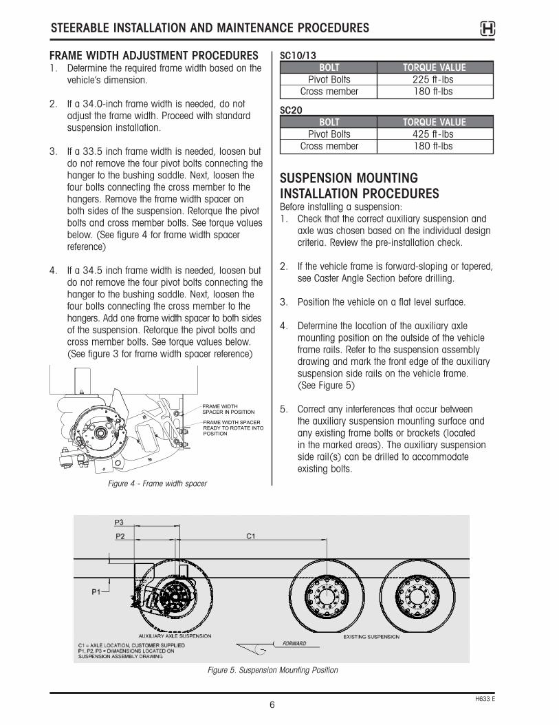
4. Determine the location of the auxiliary axlemounting position on the outside of the vehicleframe rails. Refer to the suspension assemblydrawing and mark the front edge of the auxiliarysuspension side rails on the vehicle frame. (See Figure 5)
5. Correct any interferences that occur between the auxiliary suspension mounting surface andany existing frame bolts or brackets (located in the marked areas). The auxiliary suspensionside rail(s) can be drilled to accommodateexisting bolts.
STEERABLE INSTALLATION AND MAINTENANCE PROCEDURES
6H633 E
Figure 5. Suspension Mounting Position
FRAME WIDTH ADJUSTMENT PROCEDURES1. Determine the required frame width based on the
vehicle’s dimension.
2. If a 34.0-inch frame width is needed, do notadjust the frame width. Proceed with standardsuspension installation.
3. If a 33.5 inch frame width is needed, loosen butdo not remove the four pivot bolts connecting thehanger to the bushing saddle. Next, loosen thefour bolts connecting the cross member to thehangers. Remove the frame width spacer onboth sides of the suspension. Retorque the pivotbolts and cross member bolts. See torque valuesbelow. (See figure 4 for frame width spacerreference)
4. If a 34.5 inch frame width is needed, loosen butdo not remove the four pivot bolts connecting thehanger to the bushing saddle. Next, loosen thefour bolts connecting the cross member to thehangers. Add one frame width spacer to both sidesof the suspension. Retorque the pivot bolts andcross member bolts. See torque values below.(See figure 3 for frame width spacer reference)
FRAME WIDTHSPACER IN POSITION
FRAME WIDTH SPACERREADY TO ROTATE INTOPOSITION
SC10/13BOLT TORQUE VALUE
Pivot Bolts 225 ft -lbsCross member 180 ft-lbs
SC20BOLT TORQUE VALUE
Pivot Bolts 425 ft -lbsCross member 180 ft-lbs
Figure 4 - Frame width spacer
STEERABLE INSTALLATION AND MAINTENANCE PROCEDURES
7H633 E
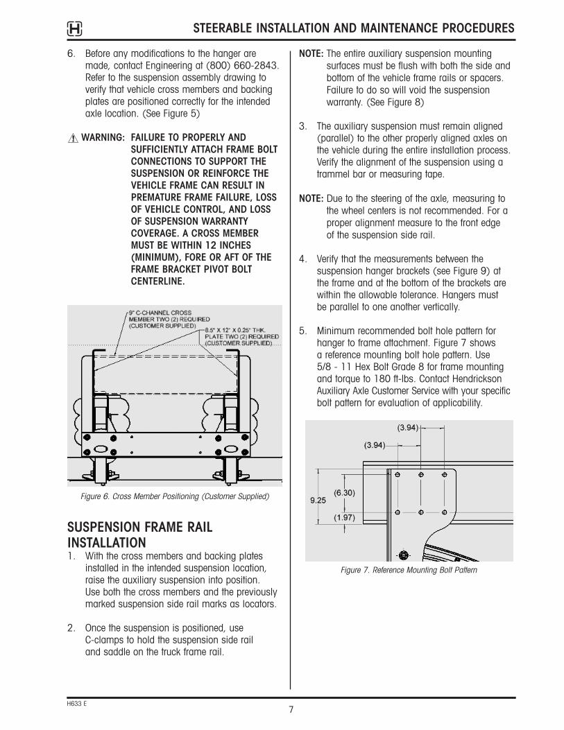
6. Before any modifications to the hanger aremade, contact Engineering at (800) 660-2843.Refer to the suspension assembly drawing toverify that vehicle cross members and backingplates are positioned correctly for the intendedaxle location. (See Figure 5)
WARNING: FAILURE TO PROPERLY ANDSUFFICIENTLY ATTACH FRAME BOLTCONNECTIONS TO SUPPORT THESUSPENSION OR REINFORCE THEVEHICLE FRAME CAN RESULT INPREMATURE FRAME FAILURE, LOSSOF VEHICLE CONTROL, AND LOSSOF SUSPENSION WARRANTYCOVERAGE. A CROSS MEMBERMUST BE WITHIN 12 INCHES(MINIMUM), FORE OR AFT OF THEFRAME BRACKET PIVOT BOLTCENTERLINE.
SUSPENSION FRAME RAILINSTALLATION1. With the cross members and backing plates
installed in the intended suspension location,raise the auxiliary suspension into position. Use both the cross members and the previouslymarked suspension side rail marks as locators.
2. Once the suspension is positioned, use C-clamps to hold the suspension side rail and saddle on the truck frame rail.
Figure 6. Cross Member Positioning (Customer Supplied)
NOTE: The entire auxiliary suspension mountingsurfaces must be flush with both the side andbottom of the vehicle frame rails or spacers.Failure to do so will void the suspensionwarranty. (See Figure 8)
3. The auxiliary suspension must remain aligned(parallel) to the other properly aligned axles onthe vehicle during the entire installation process.Verify the alignment of the suspension using atrammel bar or measuring tape.
NOTE: Due to the steering of the axle, measuring tothe wheel centers is not recommended. For aproper alignment measure to the front edge of the suspension side rail.
4. Verify that the measurements between thesuspension hanger brackets (see Figure 9) atthe frame and at the bottom of the brackets arewithin the allowable tolerance. Hangers must be parallel to one another vertically.
5. Minimum recommended bolt hole pattern forhanger to frame attachment. Figure 7 shows a reference mounting bolt hole pattern. Use 5/8 - 11 Hex Bolt Grade 8 for frame mountingand torque to 180 ft-lbs. Contact HendricksonAuxiliary Axle Customer Service with your specificbolt pattern for evaluation of applicability.
Figure 7. Reference Mounting Bolt Pattern

3. Drill one 13/16" diameter hole through the upperair spring assembly, vehicle frame rail and thecustomer supplied backing plate. Check theupper air spring plate assembly location. Fastenwith one 5/8"-11 × 2-1/4" large flange grade 8bolt, 5/8" SAE grade 8 and a 5/8" IFI grade Cprevailing-torque type steel hex flange nut. (SeeFigure 11) Torque to 180 ft-lbs.
4. Drill, install and snug the remaining fasteners onthat side.
5. Inspect the position of the opposite side of thesuspension. Make sure the upper air spring plateassembly is snug against the vehicle frame rail.Also check that the auxiliary axle is parallel toexisting axles. Repeat steps #3 and #4 for theopposite side of the suspension.
6. Remove the clamps from both sides of thevehicle frame rail.
7. Align the upper air spring stud with the hole onthe upper air spring plate assembly. Insert andreinstall fasteners.
STEERABLE INSTALLATION AND MAINTENANCE PROCEDURES
8H633 E
UPPER AIR SPRING PLATE ASSEMBLYAND AIR SPRING INSTALLATION1. Raise and position the upper air spring plate
assembly under the vehicle frame rail. Once theassembly is at the correct position (refer to thesuspension assembly drawing), clamp it to thevehicle frame rail with C-clamps.
2. With the upper air spring plate assembly tightagainst the vehicle frame rail, mark the locationof the mounting holes on the outward side of theassembly. Punch mark all hole centers. (See thesupplied suspension assembly drawing forrecommended hole locations.)
Figure 11. Upper Air Spring Plate Assembly Installation
5/8 IFI Grade CPrevailing - TorqueType Steel HexFlange Nut
5/8-11 x 2 1/4"long Grade 8Flange Bolt
Vehicle Frame Rail
Upper Air SpringPlate Assembly
Figure 10. Upper Air Spring Plate Location
Figure 9. Hanger Positioning
Figure 8. Suspension Mounting to Frame
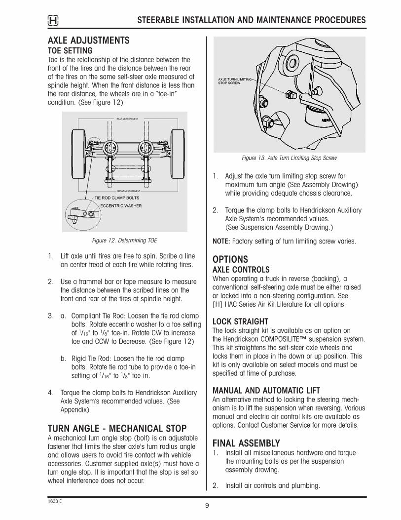
1. Adjust the axle turn limiting stop screw formaximum turn angle (See Assembly Drawing)while providing adequate chassis clearance.
2. Torque the clamp bolts to Hendrickson AuxiliaryAxle System's recommended values. (See Suspension Assembly Drawing.)
NOTE: Factory setting of turn limiting screw varies.
OPTIONSAXLE CONTROLSWhen operating a truck in reverse (backing), a conventional self-steering axle must be either raisedor locked into a non-steering configuration. See [H] HAC Series Air Kit Literature for all options.
LOCK STRAIGHTThe lock straight kit is available as an option on the Hendrickson COMPOSILITE™ suspension system.This kit straightens the self-steer axle wheels andlocks them in place in the down or up position. Thiskit is only available on select models and must bespecified at time of purchase.
MANUAL AND AUTOMATIC LIFTAn alternative method to locking the steering mech-anism is to lift the suspension when reversing. Variousmanual and electric air control kits are available asoptions. Contact Customer Service for more details.
FINAL ASSEMBLY1. Install all miscellaneous hardware and torque
the mounting bolts as per the suspensionassembly drawing.
2. Install air controls and plumbing.
AXLE ADJUSTMENTSTOE SETTINGToe is the relationship of the distance between thefront of the tires and the distance between the rear of the tires on the same self-steer axle measured atspindle height. When the front distance is less thanthe rear distance, the wheels are in a “toe-in” condition. (See Figure 12)
1. Lift axle until tires are free to spin. Scribe a lineon center tread of each tire while rotating tires.
2. Use a trammel bar or tape measure to measurethe distance between the scribed lines on thefront and rear of the tires at spindle height.
3. a. Compliant Tie Rod: Loosen the tie rod clamp bolts. Rotate eccentric washer to a toe settingof 1/16" to 1/8" toe-in. Rotate CW to increase toe and CCW to Decrease. (See Figure 12)
b. Rigid Tie Rod: Loosen the tie rod clamp bolts. Rotate tie rod tube to provide a toe-in setting of 1/16" to 1/8" toe-in.
4. Torque the clamp bolts to Hendrickson AuxiliaryAxle System’s recommended values. (SeeAppendix)
TURN ANGLE - MECHANICAL STOP A mechanical turn angle stop (bolt) is an adjustablefastener that limits the steer axle's turn radius angleand allows users to avoid tire contact with vehicleaccessories. Customer supplied axle(s) must have aturn angle stop. It is important that the stop is set sowheel interference does not occur.
STEERABLE INSTALLATION AND MAINTENANCE PROCEDURES
9H633 E
Figure 12. Determining TOE
Figure 13. Axle Turn Limiting Stop Screw

STEERABLE INSTALLATION AND MAINTENANCE PROCEDURES
10H633 E
KINGPIN LUBRICATIONOn the Hendrickson COMPOSILITE™, the kingpingrease fittings are located on the top and bottom of the kingpin grease caps.
1. Prior to greasing the kingpins on the vehicle the suspension must be in a loaded condition.
2. Clean off all the grease fittings with a cleanshop towel prior to lubrication.
3. Lubricate the kingpins through the grease fittingson the top and bottom of the steering knuckle.
4. Force the required lubricant into the upper andlower kingpin grease fittings until new lubricantflows from locations A and B. (See Figure 14)
NOTE: Greasing at the lower zerk should purgegrease from the thrust bearing shell.
KINGPIN BUSHING INSPECTIONINSPECTION PROCEDURE1. Chock the wheels to help prevent the vehicle
from moving. Set the parking brake.
2. Raise the lift axle off the ground.
CHECKING THE UPPER KINGPIN BUSHING3. Affix a magnetic base dial indicator on the axle
and place the tip of the dial indicator on theinside of the upper kingpin connection as shownin Figure 15.
3. Install wheels and torque lug nuts.
4. Check that the steer axle wheel bearings arefilled with oil by inspecting hub cap fill level.
5. Install air brake lines for the steer axle brakes,per the chassis manufacturer's specifications.
6. Inspect brakes and adjust if necessary.
NOTE: Suspensions purchased from HendricksonAuxiliary Axle Systems require brakeadjustment, however they are supplied with automatic slack adjusters.
FINAL INSPECTION1. Check that all suspension bolts are tightened
to Hendrickson Auxiliary Axle System’srecommended torque values. (See SuspensionAssembly Drawing)
2. Check the air control system for leaks and propervalve function.
3. Move the suspension through its entire travelwith wheels and tires installed to ensure thatadequate component clearances (i.e., airsprings, brake chambers, etc.) have beenprovided.
CAUTION: With the vehicle unloaded, the ride(or down) air spring air pressuremust be limited to a maximum of30 psi to avoid improper vehicleloading or component damage.
4. Inspect the auxiliary axle for the following:• Wheels lug nuts are torqued.• Wheels rotate freely.• Brakes are properly adjusted.• Wheel hubs are sufficiently filled with the
manufacturer's recommended lubricant.
PREVENTATIVE MAINTENANCERegular lubrication intervals should be followed tohelp prevent premature wear to the kingpin bushings.
GREASING AND LUBRICATION SPECIFICATIONS
KINGPINBREAK IN
KINGPINBUSHINGS
5,000 miles or asneeded
10,000 miles or every6 months
COMPONENT GREASING INTERVAL
NLGI-1 or NLGI-2
NLGI-1 or NLGI-2
GREASE
Figure 14. Kingpin Lubrication

4. If necessary, remove the wheels, hubs anddrums.
5. Place a dial indicator on each side of the axle asfollows:
a. Ensure wheels are positioned straight ahead.
b. Place the magnetic dial indicator base on theaxle.
c. Place the tip of the dial indicator on top of theupper kingpin connection.
6. Place a jack and a wood block (with a hole thatallows clearance for the lower kingpin greasefitting) under the lower kingpin grease cap area.(See Figure 16)
7. Set the dial indicator to “0” zero.
8. Raise the jack until the dial indicator shows theend of vertical travel. Measure and record thedial indicator reading. Vertical (up and down)inspection clearance must be between 0.008"and 0.030".
ADJUSTING VERTICAL END PLAY1. If vertical clearance is greater than 0.030",
replace the thrust bearing.
2. After replacing the thrust bearing, if verticalclearance is greater than 0.018", install shims(Hendrickson part no. R-001764-1Q12)between the top of the axle and the bottom of the upper kingpin connection to obtain theproper clearance specification. See the Steering Knuckle Disassembly section.
STEERABLE INSTALLATION AND MAINTENANCE PROCEDURES
11H633 E
4. Set the dial indicator to “0” zero.
5. Move the top of the tire in and out by applyingreasonable, constant pressure and thenreleasing.
6. Check the reading on the dial indicator. If thedial indicator moves more than 0.025", theupper bushing is worn or damaged. Replaceboth bushings. Refer to the Kingpin BushingRemoval and Installation sections in thispublication.
CHECKING THE LOWER KINGPIN BUSHING7. Install a dial indicator so that the base is on the
axle and the indicator tip is against the inside ofthe bottom of the knuckle.
8. Set the dial indicator to “0” zero.
IMPORTANT: If one bushing is worn or damaged, it is mandatory to replace both the topand bottom bushings on that knuckleassembly.
STEERING KNUCKLE INSPECTION AND ADJUSTMENT
CHECKING VERTICAL END PLAY(UP AND DOWN MOVEMENT)1. Chock the tires to help prevent the vehicle from
moving.
2. Set the parking brake.
3. Raise the lift axle off the ground.
Figure 15. Upper Kingpin Bushing Check
Figure 16. Vertical End Play Checking

STEERABLE INSTALLATION AND MAINTENANCE PROCEDURES
12H633 E
3. If vertical clearance is less than 0.008", removethe shims from between the top of the axle andthe bottom of the upper kingpin connection toobtain the proper clearance specification.
4. Repeat steps 2 or 3 until proper clearance isachieved.
5. Lower the jack.
STEERING KNUCKLE DISASSEMBLY1. Remove the wheel and hub assembly.
2. Remove the brake components from thesteering knuckle.
3. Remove the tie rod assembly. (See Figure 17)
4. Remove the bolts that connect upper kingpinassembly to the backbone.
WARNING: REMOVAL OF THE BOLTS WILLALLOW THE BACKBONE TOSEPARATE FROM THE AXLE WHICHCAN RESULT IN COMPONENTDAMAGE AND/OR PERSONALINJURY. BACKBONE MUST BESUPPORTED BEFORE REMOVAL OFTHE TWO BOLTS.
HINT: Remove the grease zerks from the knuckleassemblies. This will allow the knuckleassemblies to freely slide up and down thekingpins without creating bac k pressure.
5. Remove the backbone from the kingpin by sliding it down the kingpin.
6. Remove the upper kingpin assembly from theaxle by sliding it up and off the kingpin.
KINGPIN PREPARATION ANDMEASUREMENT
CLEANING THE GROUND OR POLISHED PARTS• Use a cleaning solvent to clean ground or
polished parts and surfaces. DO NOT USEGASOLINE.
Caution: Do not use hot solution tanks orwater and alkaline solutions to cleanground or polished parts. Damage tothe parts will result.
CLEANING THE ROUGH PARTS• Rough parts can be cleaned with the ground or
polished parts. Rough parts can also be cleanedin hot solution tanks with a weak alkalinesolution. The parts must remain in the hotsolution tanks until they are completely cleanedand heated.
DRYING THE CLEANED PARTS• Parts must be dried immediately after cleaning.
Dry the parts with clean paper towels, clean ragsor compressed air. Do not dry bearings byspinning with compressed air. Damage to thebearings will result.
Figure 17. Knuckle Disassembly

STEERABLE INSTALLATION AND MAINTENANCE PROCEDURES
13H633 E
PREVENTING CORROSION ON CLEANED PARTS• Apply a light coating of oil to all cleaned and
dried parts that are going to be reused. Do notapply oil to the brake lining or the brake drums.If parts are to be stored, apply an effective rustinhibitor to all surfaces.
WARNING: TO HELP PREVENT SERIOUS EYEINJURY, ALWAYS WEAR PROPEREYE PROTECTION WHEN YOUPERFORM VEHICLE MAINTENANCEOR SERVICE.
WARNING: SOLVENT CLEANERS CAN BEFLAMMABLE, POISONOUS ANDCAUSE BURNS. TO HELP AVOIDSERIOUS PERSONAL INJURY,CAREFULLY FOLLOW THEMANUFACTURER’S PRODUCTINSTRUCTIONS/GUIDELINES ANDTHE FOLLOWING PROCEDURES:1. WEAR PROPER EYEPROTECTION.2. WEAR PROTECTIVE CLOTHING.3. WORK IN A WELL-VENTILATEDAREA.4. DO NOT USE GASOLINE,SOLVENTS OR OTHER MATERIALSTHAT CONTAIN GASOLINE THATCAN EXPLODE.5. HOT SOLUTION TANKS ORALKALINE SOLUTIONS MUST BEUSED CORRECTLY. FOLLOW THE MANUFACTURER’S RECOMMENDEDINSTRUCTIONS AND GUIDELINESCAREFULLY TO HELP PREVENTPERSONAL ACCIDENT OR INJURY.
1. Prepare and polish the kingpin by removing allgrease and excess debris using a fine grit (220grit or higher) emery cloth and parts solvent.(See Figures 19 through 22)
Figure 19.
Figure 20.
Figure 21. Dirty Kingpin
Figure 22. Kingpin After Cleaning

2. Inspect the kingpin for wear or damage. Use amicrometer and measure the upper and lowerkingpin in two locations. Positions must be 90 degrees (perpendicular) from each other.(See Figures 23 through 26) If the kingpindiameter is less than 1.802", kingpinreplacement may be necessary. Contact theHendrickson Customer Service Department at 800-660-2843.
FABRICATED KNUCKLE KINGPINBUSHING INSTALLATION1. A hydraulic press with a minimum forcing
capacity of 5 tons will be required.
WARNING: BEFORE APPLYING HYDRAULICPRESSURE TO ANY TOOLING SET-UP,ALWAYS CHECK TO BE SURE THEPRESS PLATE, ADAPTERS ANDCOMPONENTS BEING WORKED ONARE POSITIONED PROPERLY, I.E. “INLINE” WITH THE RAM. IMPROPERPOSITIONING CAN CAUSEPERSONAL INJURY AND/ORCOMPONENT DAMAGE.
2. Install the backbone assembly or upper kingpinconnection in the press.
3. Remove worn kingpin bushing housing
4. Install the new kingpin housing from themachined side (axle side) of the backboneensuring squareness between the housing and the backbone.
STEERABLE INSTALLATION AND MAINTENANCE PROCEDURES
14H633 E
Figure 27.
Figure 28.
Figure 25.
Figure 26.
Figure 23.
Figure 24.

stability and corner handling. Having a proper toesetting is important for directional stability. On steerable axles, the toe is pre-set during assembly,however sometimes it becomes necessary to adjustthe toe. It is also necessary to verify the toe uponaxle installation.
For additional information regarding toe settings orlift axle systems, please contact the HendricksonCustomer Service Department at 800-660-2829.
To adjust the toe setting, follow these instructions.
DETERMINING THE TOE SETTINGWARNING: NEVER PERFORM MAINTENANCE ON
A SUSPENSION WITHOUT FIRSTRELEASING AIR PRESSURE FROMAIR SPRINGS. COMPONENTDAMAGE, INJURY OR DEATH CANOTHERWISE RESULT.
1. Lift axle until tires are free to spin.
2. Support the suspension with jack stands.
3. Scribe a line on center tread of each tire whilerotating tires.
4. Use a trammel bar or tape measure to measurethe distance between the scribed lines on the front side of the tires at spindle height.
5. Use a trammel bar or tape measure to measurethe distance between the scribed lines on theback side of the tires at spindle height.
6. Subtract the distance between the front side andback side of the tires. This is the toe setting.Toe Setting = Rear Distance - Front Distance
7. If the toe setting is set in between 1/16"and1/8", no adjustment is required. If the toesetting is set in more or less than the 1/16" to1/8" range, refer to the Adjusting the Toe Settingsection of this publication as adjustment isnecessary.
LIFT BEAM URETHANE BUSHINGSREPLACEMENT OF THE LIFT BEAM URETHANEBUSHINGS AND INNER SLEEVE.
Remove all urethane bushings and internal metalsleeves. Clean the ID of the lift beam bushing holes.Press in the urethane bushings. Lube the ID of thebushings and the OD of the sleeves with lubricantprovided in service kit. Press in the internal metalsleeves. Once completed, ensure that the inner metalsleeves are flush with the urethane bushing.
LIFT AXLE (LA) AND COMPLIANT TIEROD (CTR) STRUCTURAL INSPECTIONPeriodic inspection of the LA and CTR are stronglyrecommended. Cleaning the LA and CTR prior to theinspection will improve the ability to see all structuralcomponent condition.
Contact Hendrickson Auxiliary Axle Customer Servicefor replacement parts or parts kits (800) 660-2843.
PRE SC ROUND TUBE TIE RODADJUSTMENTIn order for a steerable suspension system to steer ortrack correctly, it is necessary for the wheels to be ina “toe-in” condition. Toe is the difference between theforemost and rearmost point on the tires at spindleheight. When the foremost distance is less than therearmost distance, the wheel pair is said to have toe-in. Toe not only affects tire wear, but also straight-line
STEERABLE INSTALLATION AND MAINTENANCE PROCEDURES
15H633 E
Figure 29. Urethane Bushing Service Kit
Pivot Bushing/Bolt Kits:SC10/13: R-008839SC10/13 Adjustable: R-008839-1SC20: R-008839-2SC20 Adjustable: R-008839-3

ADJUSTING THE TOE SETTING1. Loosen the tie rod clamp bolts, stabilizer
mounting u-bolts (if applicable) and nuts.
2. Rotate tie rod tube to provide a toe-in setting of 1/16" to 1/8".
3. Torque the clamp bolts to 50 ft-lbs.
CAST KNUCKLE KINGPIN BUSHINGREMOVALNOTE: A hydraulic press with a minimum forcing
capacity of 2.5 tons (minimum presscapacity of 5,000 psi or use an arbor press)is required.
WARNING: BEFORE APPLYING HYDRAULICPRESSURE TO ANY TOOLING SETUP,ALWAYS CHECK TO BE SURE THEPRESS PLATE, ADAPTERS ANDCOMPONENTS BEING WORKED ONARE POSITIONED PROPERLY, I.E.“IN LINE” WITH THE RAM.IMPROPER POSITIONING CANCAUSE PERSONAL INJURY ORCOMPONENT DAMAGE.
1. Remove the grease cap retaining ring.
2. Install the backbone upside down in press. Besure to support the backbone assembly so thatit sits in-line with the press. (See Figure 30)
3. Use the grease cap to press out the kingpin bushing and seal. Remove the grease zerk in the grease cap or use a hollow driver, topress out the kingpin bushing.
4. Use the same procedure to remove the kingpinbushing in the upper kingpin connection.
5. Clean the parts and then inspect beforereassembling.
CAST STEERING KNUCKLE BOREMEASUREMENT
Complete the following steering knuckle bore inspection and the measurement instructions prior to installing the kingpin bushing.
1. Measure the upper knuckle bore inside diameterat two locations. Always use an insidemicrometer or a telescoping gauge when takinga knuckle bore measurement. Some out-of-roundness at the top and bottom of the boreedges is acceptable. The steering knuckle borediameter is 1.938" +/- 0.003".
2. Measure the upper and lower bore in twopositions and at two locations. The two positionsmust be 90 degrees opposed from each other.(See Figures 31 through 32) If the averagemeasurement is more than the knuckle boremaximum diameter specification, replace theknuckle.
STEERABLE INSTALLATION AND MAINTENANCE PROCEDURES
16H633 E
Figure 31.
Figure 30.

4. Following this procedure, it is necessary to reamthe kingpin bushings to fit the kingpins. (See Kingpin Bushing Reaming Instructions.)
KINGPIN BUSHING REAMINGCaution: Ream the kingpin bushings with an
adjustable straight flute reamer. Do not hone or burnish the kingpinbushings. Honing or burnishing willdamage the bushings and void thewarranty.
WARNING: WHEN INSTALLING STEERINGKNUCKLE COMPONENTS IN A VICE,IT IS NECESSARY TO PROTECT THEMACHINED SURFACES FROM
KINGPIN BUSHING INSTALLATION1. A hydraulic shop press with a minimum
forcing capacity of 5 tons will be required.
WARNING: BEFORE APPLYING HYDRAULICPRESSURE TO ANY TOOLING SET-UP,ALWAYS CHECK TO BE SURE THEPRESS PLATE, ADAPTERS ANDCOMPONENTS BEING WORKED ONARE POSITIONED PROPERLY, I.E. “INLINE” WITH THE RAM. IMPROPERPOSITIONING CAN CAUSEPERSONAL INJURY OR COMPONENTDAMAGE.
2. Install the backbone assembly, steering arm or upper kingpin connection in the press.
3. Install the kingpin bushing from the machinedside (axle side) of the backbone using abushing driver. Press in bushing to a depth of noless than 15/64" (.236") or 6 millimeters andno more than 5/16" (.32") or 8 millimeters. (See Figures 34 and 35)
STEERABLE INSTALLATION AND MAINTENANCE PROCEDURES
17H633 E
Figure 35.
Kingpin Bushing
Machined Surface
.320
.236
Kingpin Bushing
.320
.236
Figure 34.
Machined Surface
Figure 32.
Figure 33.

out with brake cleaner and dry with compressedair.
7. Repeat steps 1 through 6 to the upper kingpinconnection.
WARNING: PRIOR TO INSTALLATION ENSURETHAT ALL RESIDUAL LOCTITEMATERIAL IS REMOVED FROM THEMOUNTING BOLTS AND THETHREADED HOLES IN THE UPPERKINGPIN CONNECTION, AND NEWLOCTITE 277 OR EQUIVALENT ISAPPLIED TO HELP ENSURE THATTHE BOLTS SUSTAIN THE PROPERTORQUE REQUIREMENT. FAILURE TODO SO CAN CAUSE LOSS OFVEHICLE CONTROL RESULTING INPERSONAL INJURY OR PROPERTYDAMAGE.
NOTE: The Hendrickson Genuine Part socket headcap screw (PN: 6110C125H4A8) comes with a pre-applied loctite compound.
8. Install the backbone and upper kingpinconnection on the kingpin.
9. Check for the proper fit by rotating the knuckleassembly back and forth to verify there is nobinding on the kingpin. (See Figures 37 and 38)
10. If the bushing is too tight, repeat steps 1 though9 until the proper clearance is achieved.
STEERABLE INSTALLATION AND MAINTENANCE PROCEDURES
18H633 E
GOUGES AND/OR MARRING BYUSING BRASS JAWS. FAILURE TODO SO CAN CAUSE PREMATUREPART DAMAGE, DAMAGE TO THESTEERING KNUCKLE COMPONENTS,LOSS OF WARRANTY, LOSS OFVEHICLE CONTROL, PERSONALINJURY OR PROPERTY DAMAGE.
1. Install the backbone assembly in a vise withbrass jaws. It is acceptable to mount the knucklecomponents in a vise either vertically orhorizontally when performing the reamingprocedure.
2. Install the reamer into the backbone until theblades touch the kingpin bushing.
NOTE: The bushing bore diameter is to be 0.001larger than the kingpin diameter.
3. Rotate the reamer smoothly with light downwardpressure. Do not apply too much pressure. (SeeFigure 36)
4. Slide the reamer out of the bottom of thebackbone assembly. If it is necessary to removethe reamer from the top, rotate the reameropposite of the cutting rotation.
5. Clean and remove all bearing material from theknuckle assembly. Be sure to remove materialfrom the grease channels and dimples.
6. Clean the 5/8" brake backing plate bolts with awire wheel and run a tap through the threads ofthe backbone / upper kingpin connection. Flush
Figure 37.
Figure 36.
Hint: The easiest way to install the knuckle is withthe grease cap not installed in the backboneassemblies. In this manner, it does not createback pressure. The assembly can then freelyslide up and down on the kingpin.
4. Raise the bottle jack so that there is no free playbetween the backbone, thrust bearing and thebottom of the axle.
5. Install the upper kingpin connection on the upperkingpin. (See Figure 41)
6. Install the left and right brake backing plate boltsfinger tight. These are for guide purposes only.
STEERABLE INSTALLATION AND MAINTENANCE PROCEDURES
19H633 E
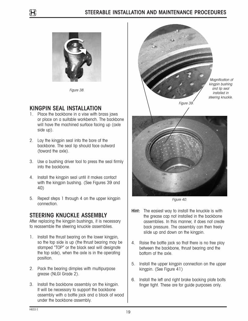
KINGPIN SEAL INSTALLATION1. Place the backbone in a vise with brass jaws
or place on a suitable workbench. The backbonewill have the machined surface facing up (axleside up).
2. Lay the kingpin seal into the bore of thebackbone. The seal lip should face outward(toward the axle).
3. Use a bushing driver tool to press the seal firmlyinto the backbone.
4. Install the kingpin seal until it makes contactwith the kingpin bushing. (See Figures 39 and40)
5. Repeat steps 1 through 4 on the upper kingpinconnection.
STEERING KNUCKLE ASSEMBLYAfter replacing the kingpin bushings, it is necessaryto reassemble the steering knuckle assemblies.
1. Install the thrust bearing on the lower kingpin, so the top side is up (the thrust bearing may bestamped “TOP” or the black seal will designatethe top side), when the axle is in the operatingposition.
2. Pack the bearing dimples with multipurposegrease (NLGI Grade 2).
3. Install the backbone assembly on the kingpin. It will be necessary to support the backboneassembly with a bottle jack and a block of woodunder the backbone assembly.
Figure 38.
Figure 40.
Magnification ofkingpin bushing
and lip sealinstalled in
steering knuckle.
Figure 39.

STEERABLE INSTALLATION AND MAINTENANCE PROCEDURES
20H633 E
NOTE: Two guide studs may be substituted in placeof the brake backing plate bolts.
7. Install the two new socket head cap screws untilthey are finger tight.
8. Apply slight upward pressure on the upperkingpin connection.
9. Insert feeler gauges between the upper kingpinconnection and the top of the axle. Check theclearance between the upper kingpin connectionand the top of the axle. (See Figure 42)
10. Remove the brake backing plate bolts andsocket head cap screws. (See Figure 41)
11. Remove the upper kingpin connection.
12. Install the appropriate amount of shims toachieve 0.008" to 0.011" clearance between theupper kingpin connection and the top of the axle.
EXAMPLE: If 0.050" clearance were measured,0.040" shims would be required toobtain the required 0.008" to 0.011"clearance.
13. Install the upper kingpin connection onto thekingpin.
14. Slide two 0.010" feeler gauges on each side of the kingpin between the axle and the upperkingpin connection.
WARNING: PRIOR TO INSTALLATION ENSURETHAT ALL RESIDUAL LOCTITEMATERIAL IS REMOVED FROM THEMOUNTING BOLTS AND THETHREADED HOLES IN THE UPPERKINGPIN CONNECTION, AND NEWLOCTITE 277 OR EQUIVALENT ISAPPLIED TO HELP ENSURE THATTHE BOLTS SUSTAIN THE PROPERTORQUE REQUIREMENT. FAILURE TO DO SO CAN CAUSE LOSS OFVEHICLE CONTROL RESULTING INPERSONAL INJURY OR PROPERTYDAMAGE.
15. Install the socket head cap screws and tighten to 175-200 ft-lbs torque.
NOTE: The Hendrickson Genuine Part socket head cap screws (PN: R-6110C125H4H8). Apply LocTite.
16. Once the final torque of the socket cap screwshas been obtained, remove the two 0.010" feelergauges and lower the bottle jack. Check theremaining bolt holes to ensure that the bolts willthread in.
Figure 41.
Figure 42.
Figure 43.
Checking vertical endplay can be performedwith the wheel endassembly on.
Block of Wood
Vertical End Play
5/8" Socket HeadCap Screws
5/8" BrakeBackingPlate Bolts

STEERABLE INSTALLATION AND MAINTENANCE PROCEDURES
21H633 E
24. Install the tie rod cross tube into the tie rod arm.
NOTE: For compliant tie rod see step 25a. For rigidtie rod see steps 25b and 26.
25a. CTR mounting bolts are torqued to 250-300 ft-lbs and refer back to the toe setting portion after this.
25b. Tighten the castle nuts to 185 ft-lbs torque, then rotate the castle nut to the next castle slot and install the cotter pin.
26. Tighten bolts to 140-160 ft-lbs torque.
NOTE: LocTite applied to knuckle assembly bolts is a critical procedure to ensure that these boltssustain the torque requirement of the kingpinconnection.
27. Install new o-rings on the grease caps andlubricate the o-rings with grease.
28. Install grease caps and new retaining rings.
17. Affix a magnetic base dial indicator on the axleand place the tip of the dial indicator on top ofthe upper kingpin connection. (See Figure 43)
18. Zero the dial indicator.
19. Raise the bottle jack until there is no clearancebetween the backbone and the bottom of theaxle.
20. Check the reading on the dial indicator. Thespecification for vertical travel on the steeringknuckle assemblies is 0.008" to 0.011".
21. If the clearance is not within the requiredspecification, repeat steps 3 through 9 until theproper clearance is obtained by adding orremoving shims.
22. If the vertical travel is not within the specification,repeat steps 3 through 16 until the propervertical travel is obtained.
23. Remove the bottle jack to remove the load offthe knuckle assembly and continue assemblingthe wheel ends.
NOTES:

STEERABLE INSTALLATION AND MAINTENANCE PROCEDURES
22H633 E
Figure 44. Maximum Auxiliary Suspension Spacing
MAXSPACING MAXIMUM
LIFT AXLETURN ANGLE
FRONT AXLEINSIDE TURNANGLE
TANDEM CENTER
WHEEL BASE
3. The number in the front axle inside turn anglecolumn (shaded area) is the maximumdistance that the self-steer axle can be placed in front of the vehicle’s rear tandem. (See Figure 44)
APPENDIX ARECOMMENDED BOLT TORQUESRefer to suspension assembly drawings for bolttorque values.
AUXILIARY SUSPENSION LOCATION1. Locate your vehicle wheel base on the table
below.
2. Follow the row to the right column that mostclosely represents your vehicle’s front inside turn angle.
COMPOSILITE™ SUSPENSION LOCATION CHART
VEHICLEWHEEL BASE
FRONT AXLE INSIDE TURN ANGLE35° 40° 45°120"140" 100" 84"137"160" 115" 96"154"180" 129" 108"171"200" 143" 120"189"220" 157" 132"206"240" 172" 144"223"260" 186" 156"240"280" 201" 168"
Table 1. Suspension Location Chart
MAXIMUM CAPACITY APPLICATION WEIGHT RIDE HEIGHTSMODEL (lbs.)(lbs.)
Truck Trailer (SCW)(inches +/- 1")
SC10 10,000 675 664 12.5 - 20.5SC13 13,500 796 785 8.5 - 18.5SC20 20,000 1,340 1,315 9.5 - 13.5
SCO13 13,500 856 N/A 8.5 - 18.5SCO20 20,000 1,326 N/A 9.5 - 13.5SCH10 10,000 1,133 N/A 10.5 - 20.5SCR13 13,500 1,029 N/A 9.0 - 15.0
COMPOSILITE™ STEERABLE LIFT AXLE SPECIFICATIONS
Table 2. Steerable Lift Axle Specifications

STEERABLE INSTALLATION AND MAINTENANCE PROCEDURES
23H633 E
Figure 45. HAC Series Air Kit
APPENDIX BBRAKE REPLACEMENT
WARNING: ADEQUATE SUSPENSION SUPPORTMUST BE PROVIDED! FAILURE TOPROVIDE ADEQUATE SUSPENSIONSUPPORT COULD RESULT INSERIOUS BODILY HARM OR FATALINJURY. EYE PROTECTIONSTRONGLY RECOMMENDED
For replacement brake kits, contact the HendricksonCustomer Service Department at (800) 660-2843
1. Raise and support the suspension to which thebrakes are to be replaced. Remove wheel, brakedrum and axle end components to expose thebrake shoes.
2. Remove the outer retaining spring and innerretaining spring.

Printed in United States of America
www.hendrickson-intl.com
Information contained in this literature was accurate at the time of publication. Product changes may have been made after the copyright date that are not reflected.© 2011 Hendrickson USA, L.L.C. (U.S. Rights) Hendrickson International Corporation (Rights Outside U.S.) All Rights ReservedH633 Rev E 5-11
Auxiliary Axle Systems277 North High StreetHebron, OH 43025 USA740.929.5600Fax 740.929.5601
Auxiliary Axle Systems250 Chrysler Drive, Unit #3Brampton, ON L6S 6B6 Canada905.789.1030Fax 905.789.1033
5. Replacement brake kit for each specific axle will have the necessary parts to be replaced.Discard worn or damaged parts. If a part is not included in the kit, contact customer service (800) 660-2843.
6. Install new parts in reverse order from step 4.Brake bolts through the anchor pin are to beinstalled with a torque of 160 ft-lbs.
When reinstalling the spring, be sure the spring iscompletely clipped into the mounting hole. Failure to do so could result in brake failure.
3. Support the lower brake shoe assembly andremove the return spring. Set parts aside andremove the upper brake shoe.
4. Remove the brake bolts and brake anchor pin. If lock straight target is present, note position for proper reassembly location.
Figure 46. Removal of Outer and Inner Retaining Spring
Figure 47. Removal of Return Spring
Figure 48. Removal of Brake Bolts and Anchor Pin
Figure 49. Spring Clipped Completely Into Mounting Hole
STEERABLE INSTALLATION AND MAINTENANCE PROCEDURES