Embed Size (px)
Citation preview

H.264 Decoder Algorithm Specification and Simulation in Simulink and PeaCE
Seongnam Kwon Hyunuk Jung Soonhoi Ha
The School of Electrical Engineering and Computer Science Seoul National University Seoul 151-742, KOREA
{ksn, jung, sha}@iris.snu.ac.kr
Abstract – Model-based approach is widely adopted to develop embedded system to cope with the ever-increasing complexity of system design under relentless time-to-market pressure. In this paper we present our experience of H.264 decoder algorithm specification and simulation with two model-based design environments, Simulink and PeaCE. Formal data-driven model of PeaCE can specify multi-rate DSP systems more easily than time-driven model of Simulink. In addition, PeaCE has advantages over Simulink in terms of simulation speed, debugging capability, and code reuse. It is attributed to the compiled-simulation approach of PeaCE where the system simulation is performed with an automatically generated code from the specification
Keywords: codesign, system level specification, model-based, H.264 decoder, Simulink, PeaCE
1 Introduction Model-based approach is widely adopted to develop
embedded system to cope with the ever-increasing complexity of system design under relentless time-to-market pressure. In a model-based approach, the system algorithm is specified with a block diagram or a composition of function blocks that can be reused in other systems. With a block diagram specification, system-level design decision such as HW/SW partitioning and scheduling can be made more easily.
Fig.1 (a) shows a general development flow where the system algorithm is first specified with a block diagram, next simulated with a high level language like C, and finally implemented with a target language such as C, assembly, or HDL. If this flow is performed manually, a system must be rewritten in many languages manually. It introduces the risk that translation from a block diagram or one language to other language may be inaccurate and accumulate translation errors. Therefore many tools have been developed to automate such translation from specification to simulation and even up to implementation. Simulink[6] of the MathWorks may be the most popular tool for the front end design of system specification and simulation.
Simulink has strong modeling capability to support linear and nonlinear systems, continuous and discrete systems or a hybrid of them. And it is provided with abundant sets of predefined function blocks. Nonetheless, we have encountered several difficulties of using Simulink to specify and simulate an H.264 decoder algorithm. In this paper we present our design experience with Simulink and compare it with our design tool, PeaCE[5].
In our case study with an H.264[4] decoder algorithm, we start with a reference C code of the algorithm[3]. From the sequential C code, we construct a block diagram specification that is similar to the flow chart displayed in the H.264 standard document. Then we perform simulation to verify the correctness of the algorithm specification. In this process we compare Simulink and PeaCE in the following three aspects: (1)algorithm modeling of multirate system, (2)block definition and debugging, and (3)simulation performance.
ModelingModeling SimulationSimulation&Verification&Verification
int main() {…}
ImplementationImplementation
C, Assembly, VHDL…
ModelingModeling SimulationSimulation&Verification&Verification
ImplementationImplementation
(Automatically generated code)
(a)
(b)
ModelingModeling Simulation & VerificationSimulation & Verification(Automatically generated C code)
ImplementationImplementation(Automatically generated C/HDL code)
(c)
Fig.1 Model-based design flow. (a) general flow, (b) Simulink flow and (c) PeaCE flow.
Figure 1(b) and (c) show the design flows of Simulink and PeaCE respectively. A clear distinction of PeaCE design flow is that system simulation as well as implementation is performed with the automatically generated code. There are three main advantages of this

scheme: simulation speed, debugging capability, and code reuse. The PeaCE approach is a compiled simulation which is much faster than an approach of Fig.1 (b) where models are simulated by a simulation engine. When an error occurs, the proposed scheme can debug the generated code using conventional debugger while the special debugging capability should be provided by the simulation engine in Fig.1 (b). Last but not the least, the same model definition is used in the generated codes for simulation and implementation of the system in the proposed approach.
The rest of the paper is organized as follows. Section 2 describes a modeling issue of H.264 decoder algorithm. Section 3 and section 4 describe how H.264 decoder algorithm can be specified in Simulink and PeaCE respectively. Simulation performance of Simulink and PeaCE is compared in section 5. At last section 6 concludes this paper.
2 H.264 Decoder Algorithm H.264 is a video coding standard (or
Recommendation) made by the Video Coding Experts Group (VCEG) of the International Telecommunication Union Telecommunication Standardisation Sector (ITU-T). While H.264 achieves bit rate saving ratio up to 50% compared to H.263+ and offers consistently good video quality at most bit rates, algorithm complexity grows significantly. More efficient compression and high quality video are attributed to the following features: Enhanced motion compensation, small blocks (4x4) for transform coding, improved in-loop deblocking filter, and enhanced entropy coding
Read Slice
DecodeMB
Inverse Transform
Intra16 Prediction
Intra Prediction
Inter Prediction
MUX
+
MakeFrame
Deblockfilter
Write Fram
e
1 1
1 1
1
1
1
11
1
1
1
1
1
1 1 1
11
1584
1584
1584
1584
15841584
1 1
1
1
1
1
1584
1584
1584
1584
1
1
1
1 1
1
1
1
Y componentY component
U componentU component
V componentV component
1584/4
1584/4
1
1
1
1
1 1
1
Fig.2 the blockdiagram of H.264 decoder (baseline profile)
Fig.2 shows the simplified block diagram of the an H.264 decoder algorithm, baseline profile. For simplicity, the inside structure is revealed only for Y component while U and V components have similar inside structure. In Fig.2, numbers on arch represent the sample rates that each block consumes or produces per invocation. For example ‘Deblock MB’ block reads one frame sample from ‘Read Slice’ block and writes 1584 4x4-block
samples to ‘Inverse Transform’ block. Different sample rates make execution rate of blocks different: ‘Inverse Transform’ block should be executed 1584 times as ‘Read Slice’ block is executed only once. It is very common in multimedia applications that block execution rate is different. Fig.2 also shows that the sample rates for U and V components are 1/4 of that for Y component. How to specify such multirate execution is the main concern in algorithm specification.
Diamond-like shape represents a sample delay. For example, a sample delay is needed between ‘Make Frame’ block and ‘Intra Prediction’ block to make a prediction from the previously decoded blocks. Initially, null sample is fed into the ‘Intra Prediction’ block. Note that such sample delays exist in all feedback loops in the block diagram.
3 H.264 Decoder Modeling in Simulink Simulink is an extension to MATLAB® that allows
developers to rapidly build computer models of dynamic systems. It uses block diagram for modeling system and provides graphical user interface. The standard Simulink block set includes continuous blocks and discrete blocks. Continuous blocks respond to continuously changing input. Discrete blocks, in contrast, respond to changes in input only at integer multiples of a fixed interval. To model H.264 decoder we use discrete blocks.
3.1 Algorithm modeling of multi-rate system
Read SliceRead Slice
Decode MBDecode MBY Y
U U
V V
DeblockDeblock& Write& Write
Slice ClockSlice Clock
4x4 block 4x4 block ClockClock
Fig.3 Top model of H.264 decoder in Simulink
Since discrete blocks of Simulink are time-driven, blocks should be explicitly triggered by clock inputs. And multi-rate execution is modeled by multiple clock signals of different periods. Fig.3 shows the top-level specification of H.264 decoder in Simulink, where two different clock blocks are used to trigger ‘Read Slice’
block and the other blocks. As ‘Slice clock’ block sends one clock signal, ‘4x4 block Clock’ block produces 1584 output signals. It is because one slice is composed of 1584 4x4 blocks in QCIF(176*144) format.
Each block except clock block is a macro-block that includes a block diagram inside. If a macro-block is triggered by a clock signal, the block diagram inside the macro-block is executed once according to the predetermined execution order.
In Simulink, buffer is needed to store data between blocks that have different execution rates. To know when to update the buffer and when to execute the block, counter variable is needed inside the block definition. The counter variable is increased each time clock signal arrives and is initialized when block updates the buffer or is executed properly. Separate buffer and counter are needed for each input or output port of block. In case a block has many ports and is connected to blocks of different rate, it is cumbersome to manage buffers and counters to model the multi-rate execution correctly: Unfortunately, the H.264 decoder example is the case.
Note that U and V subsystems use the same clock input as Y subsystem though 4:2:0 YUV format is used so that U and V subsystems have different sample rates from Y subsystem. We realize such multi-rate execution with counters. U and V components are executed when the counter value become a multiple of 4 to model 1/4 sample rate of Y component. In short, multi-rate execution is realized by a combination of multiple clocks and careful buffer and counter management.
3.2 Block definition and debugging
In a model-based design, defining and debugging a block is most time consuming. From the reference C code of H.264 decoder algorithm, we identified the code section associated with each functional block and rearranged the variable definitions and access methods to make the block self-contained. Instead of redefining each block in MATLAB language, we imported this rearranged C code section in the body of each block. Simulink provide S-function[7] for this purpose.
S-function is a computer language description of a Simulink block. Engineers can use their familiar languages such as C, C++, Ada, or Fortan, for modeling blocks with S-functions. All languages except MATLAB are compiled as MEX-files using the mex utility at compile time and these MEX-files are called in Simulink at simulation time. S-function has a special calling syntax and this enables interaction between Simulink and S-functions.
There are two methods to use S-function. First one is to use S-function builder that has a fixed type signature. But it is too restricted to describe complex H.264 blocks.
Therefore we chose the other method of writing S-function block manually.
Fig. 4 shows the structure of block definition we used for H.264 decoder blocks. Note that we separate a wrapper function and the actual function. The wrapper function is defined as an S function and the actual function code is called inside the wrapper function. The wrapper file is compiled with the actual function file using mex utility, to generate a MEX-file. At first we tried to define the actual function code as an S function without wrapper intervention. Then Simulink failed to simulate the system. But it was not possible to identify what was the problem while we suspected that there was some error in block definition. The problem was disappeared when the wrapper function was introduced without any modification of actual function code. In addition, generating debug information using the printf function is only available in the wrapper file, not in the actual function code: It also makes system debugging difficult.
Simulink itself is a simulation engine, which determines which block to invoke next and invoke the block. If some block has a critical bug, it kills the simulator, that is Simulink itself. And we could not figure out how to use debugger for Simulink. In summary we found it extremely difficult to debug the functionality of S-function block in Simulink.
SimulinkSimulation
Engine
wrapper actual function
Special calling syntaxSpecial calling syntax Function callFunction call
‘‘mexmex’’--generated MEXgenerated MEX--filefile
Fig.4 Block organization of H.264 decoder in Simulink
4 H.264 Decoder Modeling in PeaCE
PeaCE is a codesign environment for rapid development of heterogeneous digital systems. It provides the design framework to all system level design activities: specification, cosimulation, design space exploration, interactive partitioning, synthesis of HW, SW and their interface. 4.1 Algorithm modeling of multi-rate system
PeaCE uses an extended synchronous dataflow (SDF[2]) model[1] for functional specification. In SDF model, a block is executable as soon as it receives the specified number of samples at all input ports. And the block produces the specified number of samples at all output ports per each invocation. The number of samples consumed (or produced) at each input (or output) port per block invocation is fixed at compile time. These restrictions make the model formal and data-driven.
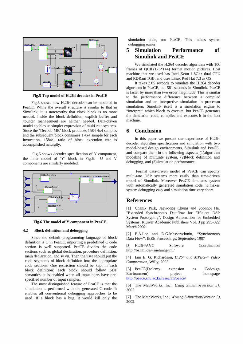
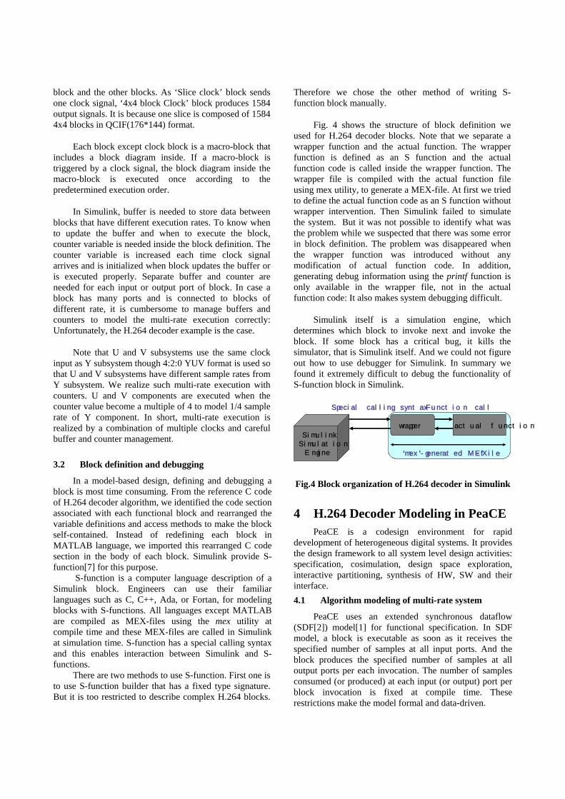
Fig.5 Top model of H.264 decoder in PeaCE
Fig.5 shows how H.264 decoder can be modeled in PeaCE. While the overall structure is similar to that in Simulink, it is noteworthy that clock block is no more needed. Inside the block definition, explicit buffer and counter management are neither needed. Data-driven model enables us simpler expression of multi-rate systems. Since the ‘Decode MB’ block produces 1584 4x4 samples and the subsequent block consumes 1 4x4 sample for each invocation, 1584:1 ratio of block execution rate is accomplished naturally.
Fig.6 shows decoder specification of Y component, the inner model of ‘Y’ block in Fig.6. U and V components are similarly modeled.
Fig.6 The model of Y component in PeaCE
4.2 Block definition and debugging
Since the default programming language of block definition is C in PeaCE, importing a predefined C code section is well supported. PeaCE divides the code sections such as global declaration, procedure definition, main declaration, and so on. Then the user should put the code segments of block definition into the appropriate code sections. One restriction should be kept in each block definition: each block should follow SDF semantics: it is enabled when all input ports have pre-specified number of input samples.
The most distinguished feature of PeaCE is that the simulation is performed with the generated C code. It enables all conventional debugging approaches to be used. If a block has a bug, it would kill only the
simulation code, not PeaCE. This makes system debugging easier.
5 Simulation Performance of Simulink and PeaCE We simulated the H.264 decoder algorithm with 100
frames of QCIF(176*144) format motion pictures. Host machine that we used has Intel Xeon 1.8Ghz dual CPU and RDRam 1GB, and uses Linux Red Hat 7.3 as OS.
It takes 2.05 seconds to simulate the H.264 decoder algorithm in PeaCE, but 581 seconds in Simulink. PeaCE is faster by more than two order magnitude. This is similar to the performance difference between a compiled simulation and an interpretive simulation in processor simulation. Simulink itself is a simulation engine to “interpret” which block to execute, but PeaCE generates the simulation code, compiles and executes it in the host machine.
6 Conclusion In this paper we present our experience of H.264
decoder algorithm specification and simulation with two model-based design environments, Simulink and PeaCE, and compare them in the following aspects: (1)algorithm modeling of multirate system, (2)block definition and debugging, and (3)simulation performance.
Formal data-driven model of PeaCE can specify multi-rate DSP systems more easily than time-driven model of Simulink. Moreover PeaCE simulates system with automatically generated simulation code: it makes system debugging easy and simulation time very short.
References [1] Chanik Park, Jaewoong Chung and Soonhoi Ha, "Extended Synchronous Dataflow for Efficient DSP System Prototyping", Design Automation for Embedded Systems, Kluwer Academic Publishers Vol. 3 pp 295-322 March 2002.
[2] E.A.Lee and D.G.Messerschmitt, “Synchronous Data Flow”, IEEE Proceedings, September, 1987
[3] H.264/AVC Software Coordination http://bs.hhi.de/~suehring/tml/
[4] Iain E. G. Richardson, H.264 and MPEG-4 Video Compression, Willy, 2003.
[5] PeaCE(Ptolemy extension as Codesign Environment) project homepage http://peace.snu.ac.kr/research/peace/
[6] The MathWorks, Inc., Using Simulink(version 5), 2002.
[7] The MathWorks, Inc., Writing S-functions(version 5), 2002.