Embed Size (px)
Citation preview
MAKING MODERN LIVING POSSIBLE
Electrical Installation
H1 PumpElectrical Displacement Control(EDC)
powersolutions.danfoss.com
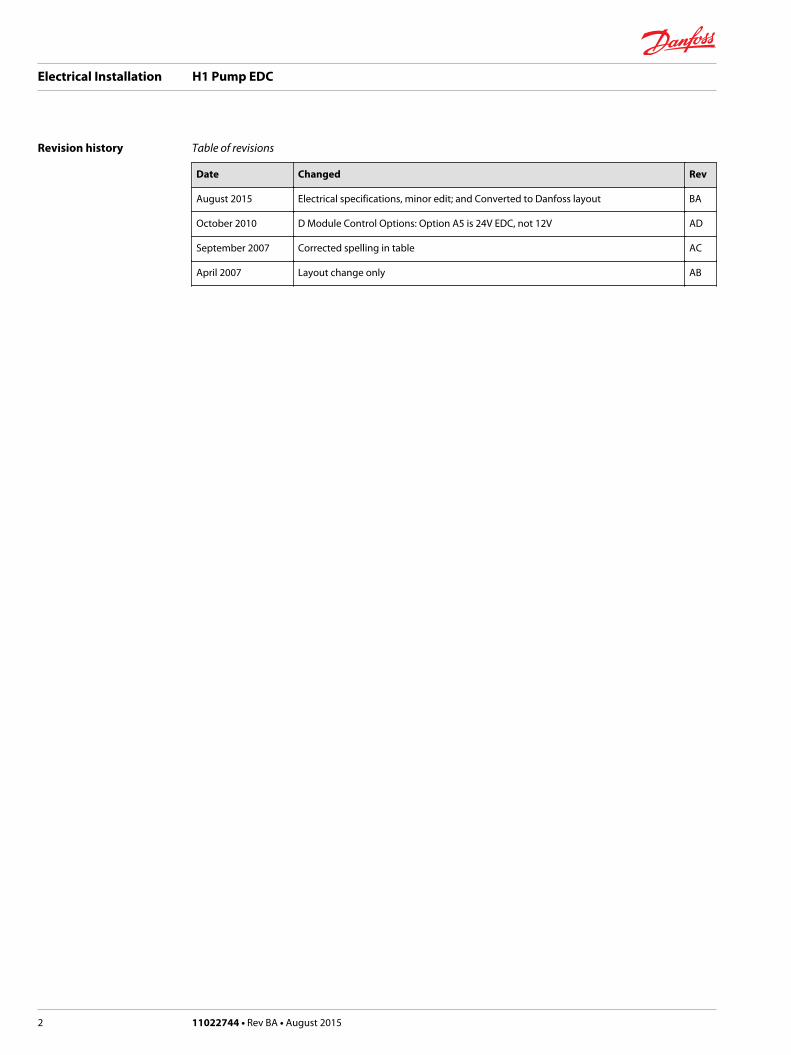
Revision history Table of revisions
Date Changed Rev
August 2015 Electrical specifications, minor edit; and Converted to Danfoss layout BA
October 2010 D Module Control Options: Option A5 is 24V EDC, not 12V AD
September 2007 Corrected spelling in table AC
April 2007 Layout change only AB
Electrical Installation H1 Pump EDC
2 11022744 • Rev BA • August 2015
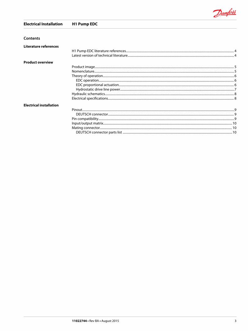
Literature referencesH1 Pump EDC literature references........................................................................................................................................... 4Latest version of technical literature......................................................................................................................................... 4
Product overviewProduct image................................................................................................................................................................................... 5Nomenclature....................................................................................................................................................................................5Theory of operation.........................................................................................................................................................................6
EDC operation.............................................................................................................................................................................. 6EDC proportional actuation.................................................................................................................................................... 6Hydrostatic drive line power...................................................................................................................................................7
Hydraulic schematics...................................................................................................................................................................... 8Electrical specifications.................................................................................................................................................................. 8
Electrical installationPinout....................................................................................................................................................................................................9
DEUTSCH connector.................................................................................................................................................................. 9Pin compatibility...............................................................................................................................................................................9Input/output matrix...................................................................................................................................................................... 10Mating connector.......................................................................................................................................................................... 10
DEUTSCH connector parts list .............................................................................................................................................10
Electrical Installation H1 Pump EDC
Contents
11022744 • Rev BA • August 2015 3
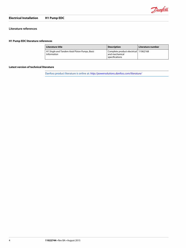
H1 Pump EDC literature references
Literature title Description Literature number
H1 Single and Tandem Axial Piston Pumps, BasicInformation
Complete product electricaland mechanicalspecifications
11062168
Latest version of technical literature
Danfoss product literature is online at: http://powersolutions.danfoss.com/literature/
Electrical Installation H1 Pump EDC
Literature references
4 11022744 • Rev BA • August 2015
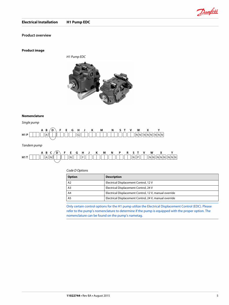
Product image
H1 Pump EDC
Nomenclature
Single pump
A B D F E G H J K M N S T V W X YH1 P A G N N N N N N N N
Tandem pump
A B C D F E G H J K M N P R S T V W X YH1 T A N N F N P N N N N N N N N
Code D Options
Option Description
A2 Electrical Displacement Control, 12 V
A3 Electrical Displacement Control, 24 V
A4 Electrical Displacement Control, 12 V, manual override
A5 Electrical Displacement Control, 24 V, manual override
Only certain control options for the H1 pump utilize the Electrical Displacement Control (EDC). Pleaserefer to the pump’s nomenclature to determine if the pump is equipped with the proper option. Thenomenclature can be found on the pump’s nametag.
Electrical Installation H1 Pump EDC
Product overview
11022744 • Rev BA • August 2015 5
Theory of operation
The Non Feedback Proportional Electric (NFPE) control is an electrical automotive control in which anelectrical input signal activates one of two proportional solenoids that port charge pressure to either sideof the pump servo cylinder. The NFPE control has no mechanical feedback mechanism.
The pump displacement is proportional to the solenoid signal current, but it also depends upon pumpinput speed and system pressure. This characteristic also provides a power limiting function by reducingthe pump swashplate angle as system pressure increases.
EDC operation
H1 Electrical Displacement Control's (EDC) are current driven controls requiring a Pulse Width Modulated(PWM) signal. Pulse width modulation allows more precise control of current to the solenoids. The PWMsignal causes the solenoid pin to push against the porting spool, which pressurizes one end of the servopiston, while draining the other. Pressure differential across the servo piston moves the swashplate. Aswashplate feedback link, opposing control links, and a linear spring provide swashplate position forcefeedback to the solenoid. The control system reaches equilibrium when the position of the swashplateexactly balances the input command from the operator (solenoid). As hydraulic pressures in theoperating loop change with load, the control assembly and servo/swashplate system work constantly tomaintain the commanded position of the swashplate.
The EDC incorporates a positive neutral deadband as a result of the control spool porting, preloads fromthe servo piston assembly, and the linear control spring. Once the neutral threshold current is reached,the swashplate is positioned directly proportional to the control current. To minimize the effect of thecontrol neutral deadband, we recommend the transmission controller or operator input deviceincorporate a jump up current to offset a portion of the neutral deadband.
The neutral position of the control spool does provide a positive preload pressure to each end of theservo piston assembly.
When the control input signal is either lost or removed, or if there is a loss of charge pressure, the spring-loaded servo piston will automatically return the pump to the neutral position.
A serviceable 125 μm screen is located in the supply line immediately before the control porting spool.
An EDC is a displacement (flow) control. Pump swashplate position is proportional to the input commandand therefore vehicle or load speed (excluding influence of efficiency), is dependent only on the primemover speed or motor displacement.
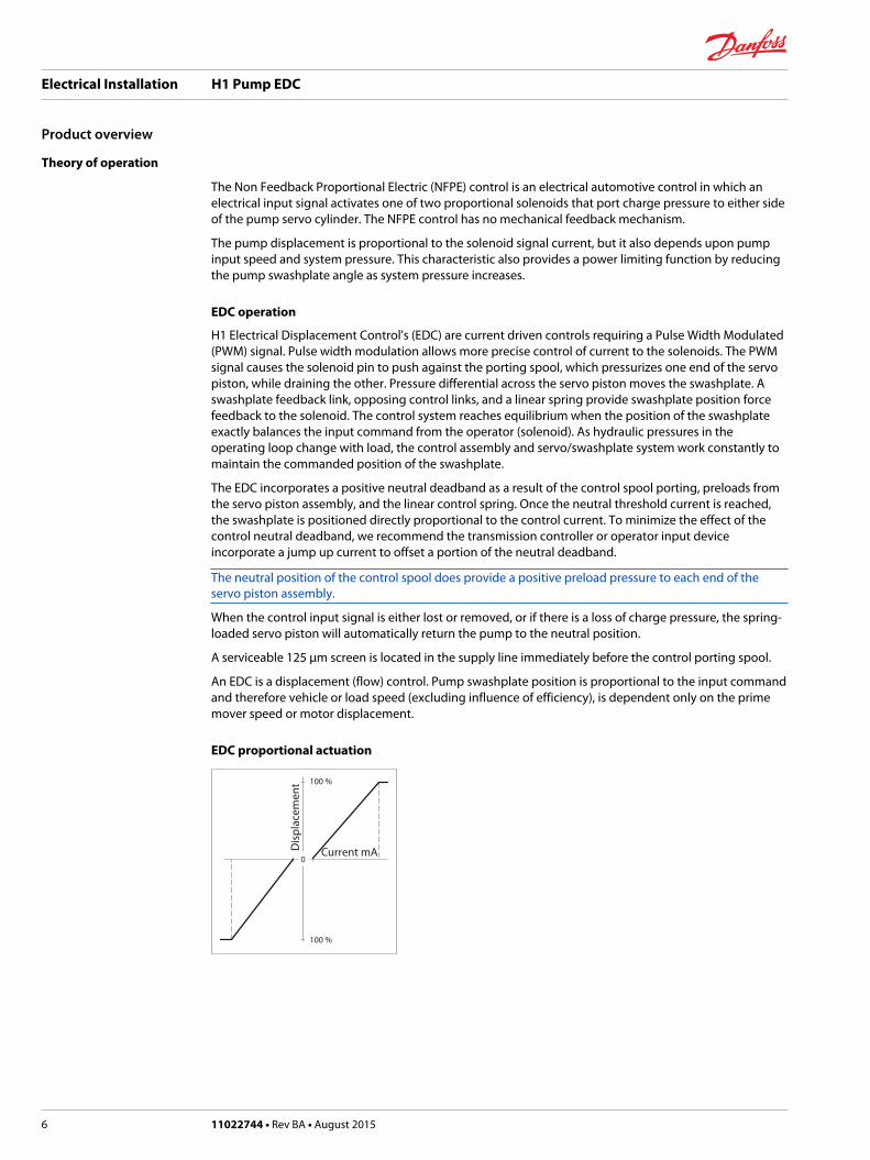
EDC proportional actuation
0
100 %
100 %
Dis
plac
emen
t
Current mA
Electrical Installation H1 Pump EDC
Product overview
6 11022744 • Rev BA • August 2015
Hydrostatic drive line power
W Warning
Unintended vehicle or machine movement hazard. The loss of hydrostatic drive line power, in any modeof operation (forward, neutral, or reverse) may cause the system to lose hydrostatic braking capacity. Youmust provide a braking system, redundant to the hydrostatic transmission, sufficient to stop and hold thevehicle or machine in the event of hydrostatic drive power loss.
Electrical Installation H1 Pump EDC
Product overview
11022744 • Rev BA • August 2015 7
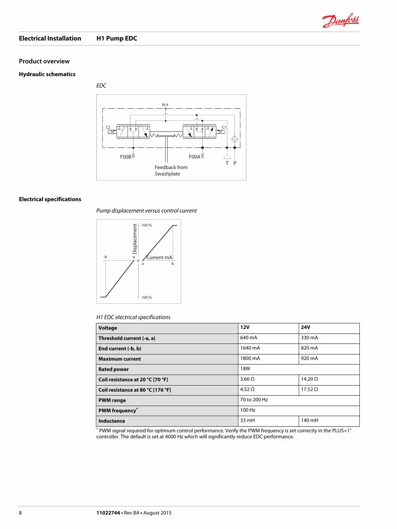
Hydraulic schematics
EDC
C2 C1
F00B F00A
M 4
T PFeedback from Swashplate
Electrical specifications
Pump displacement versus control current
0-b -a
ba
100 %
100 %
Dis
plac
emen
t
Current mA
H1 EDC electrical specifications
Voltage 12V 24V
Threshold current (-a, a) 640 mA 330 mA
End current (-b, b) 1640 mA 820 mA
Maximum current 1800 mA 920 mA
Rated power 18W
Coil resistance at 20 °C [70 °F] 3.66 Ω 14.20 Ω
Coil resistance at 80 °C [176 °F] 4.52 Ω 17.52 Ω
PWM range 70 to 200 Hz
PWM frequency* 100 Hz
Inductance 33 mH 140 mH
* PWM signal required for optimum control performance. Verify the PWM frequency is set correctly in the PLUS+1®
controller. The default is set at 4000 Hz which will significantly reduce EDC performance.
Electrical Installation H1 Pump EDC
Product overview
8 11022744 • Rev BA • August 2015
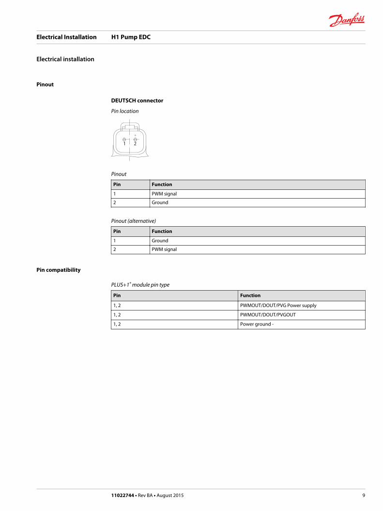
Pinout
DEUTSCH connector
Pin location
1 2
Pinout
Pin Function
1 PWM signal
2 Ground
Pinout (alternative)
Pin Function
1 Ground
2 PWM signal
Pin compatibility
PLUS+1® module pin type
Pin Function
1, 2 PWMOUT/DOUT/PVG Power supply
1, 2 PWMOUT/DOUT/PVGOUT
1, 2 Power ground -
Electrical Installation H1 Pump EDC
Electrical installation
11022744 • Rev BA • August 2015 9
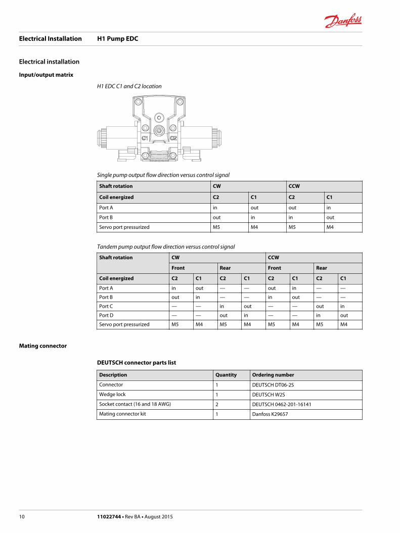
Input/output matrix
H1 EDC C1 and C2 location
Single pump output flow direction versus control signal
Shaft rotation CW CCW
Coil energized C2 C1 C2 C1
Port A in out out in
Port B out in in out
Servo port pressurized M5 M4 M5 M4
Tandem pump output flow direction versus control signal
Shaft rotation CW CCW
Front Rear Front Rear
Coil energized C2 C1 C2 C1 C2 C1 C2 C1
Port A in out — — out in — —
Port B out in — — in out — —
Port C — — in out — — out in
Port D — — out in — — in out
Servo port pressurized M5 M4 M5 M4 M5 M4 M5 M4
Mating connector
DEUTSCH connector parts list
Description Quantity Ordering number
Connector 1 DEUTSCH DT06-2S
Wedge lock 1 DEUTSCH W2S
Socket contact (16 and 18 AWG) 2 DEUTSCH 0462-201-16141
Mating connector kit 1 Danfoss K29657
Electrical Installation H1 Pump EDC
Electrical installation
10 11022744 • Rev BA • August 2015

Electrical Installation H1 Pump EDC
11022744 • Rev BA • August 2015 11

Electrical Installation H1 Pump EDC
12 11022744 • Rev BA • August 2015

Electrical Installation H1 Pump EDC
11022744 • Rev BA • August 2015 13
Danfoss Power Solutions is a global manufacturer and supplier of high-quality hydraulic andelectronic components. We specialize in providing state-of-the-art technology and solutionsthat excel in the harsh operating conditions of the mobile off-highway market. Building onour extensive applications expertise, we work closely with our customers to ensureexceptional performance for a broad range of off-highway vehicles.
We help OEMs around the world speed up system development, reduce costs and bringvehicles to market faster.
Danfoss – Your Strongest Partner in Mobile Hydraulics.
Go to www.powersolutions.danfoss.com for further product information.
Wherever off-highway vehicles are at work, so is Danfoss. We offer expert worldwide supportfor our customers, ensuring the best possible solutions for outstanding performance. Andwith an extensive network of Global Service Partners, we also provide comprehensive globalservice for all of our components.
Please contact the Danfoss Power Solution representative nearest you.
Local address:
Danfoss Power Solutions GmbH & Co. OHGKrokamp 35D-24539 Neumünster, GermanyPhone: +49 4321 871 0
Danfoss Power Solutions ApSNordborgvej 81DK-6430 Nordborg, DenmarkPhone: +45 7488 2222
Danfoss Power Solutions (US) Company2800 East 13th StreetAmes, IA 50010, USAPhone: +1 515 239 6000
Danfoss Power Solutions Trading(Shanghai) Co., Ltd.Building #22, No. 1000 Jin Hai RdJin Qiao, Pudong New DistrictShanghai, China 201206Phone: +86 21 3418 5200
Danfoss can accept no responsibility for possible errors in catalogues, brochures and other printed material. Danfoss reserves the right to alter its products without notice. This also applies toproducts already on order provided that such alterations can be made without changes being necessary in specifications already agreed.All trademarks in this material are property of the respective companies. Danfoss and the Danfoss logotype are trademarks of Danfoss A/S. All rights reserved.
11022744 • Rev BA • August 2015 www.danfoss.com © Danfoss A/S, 2015
Products we offer:
• Bent Axis Motors
• Closed Circuit Axial PistonPumps and Motors
• Displays
• Electrohydraulic PowerSteering
• Electrohydraulics
• Hydraulic Power Steering
• Integrated Systems
• Joysticks and ControlHandles
• Microcontrollers andSoftware
• Open Circuit Axial PistonPumps
• Orbital Motors
• PLUS+1® GUIDE
• Proportional Valves
• Sensors
• Steering
• Transit Mixer Drives
Comatrolwww.comatrol.com
Schwarzmüller-Inverterwww.schwarzmueller-inverter.com
Turolla www.turollaocg.com
Hydro-Gearwww.hydro-gear.com
Daikin-Sauer-Danfosswww.daikin-sauer-danfoss.com