Embed Size (px)
Citation preview

H-4SDI(4HDMI)-QAM-IP
4 SDI(HDMI) to 4 DVB-C Encoder
Modulator
(MPEG-2 HD/MPEG-4 HD Encoding + DVB-C Modulating)
4 SDI or 4 HDMI
Revision 2.1

H-4SDI-or-4HDMI-QAM-IP
About This Manual
Intended Audience
This user manual has been written to help people who have to use, integrate and to install
the product. Some chapters require some prerequisite knowledge in electronics and
especially in broadcast technologies and standards.
Disclaimer
No part of this document may be reproduced in any form without the written permission of
Thor Broadcast.
The contents of this document are subject to revision without notice due to continued
progress in methodology, design and manufacturing. Thor shall have no liability for any
error or damage of any kind resulting from the use of this document.
Copy Warning
This document includes some confidential information. Its usage is limited to the owners
of the product that it is relevant to. It cannot be copied, modified, or translated in another
language without prior written authorization from Thor Broadcast.
***Note – This manual is intended for the
Thor H-QAM-IP chassis, this guide is
universal for both HDMI & SDI units.

H-4SDI-or-4HDMI-QAM-IP
Directory
Contents
CHAPTER 1 INTRODUCTION ........................................................................................................................................................ 4
1.1 PRODUCT OVERVIEW ....................................................................................................................................................................... 4
1.2 KEY FEATURES ................................................................................................................................................................................ 4
1.3 SPECIFICATIONS ............................................................................................................................................................................... 5
1.4 SCHEMATIC OVERVIEW.................................................................................................................................................................... 6
1.5 PRINCIPLE CHART ............................................................................................................................................................................ 7
1.6 TYPICAL APPLICATION OF 4 * CARRIER OUTPUTS ........................................................................................................................... 7
1.7 APPEARANCE AND DESCRIPTION ..................................................................................................................................................... 8
CHAPTER 2 INSTALLATION GUIDE ............................................................................................................................................. 10
2.1 GENERAL PRECAUTIONS ................................................................................................................................................................ 10
2.2 POWER PRECAUTIONS ................................................................................................................................................................... 10
2.3 DEVICE’S INSTALLATION FLOW CHART ILLUSTRATED AS FOLLOWING .......................................................................................... 10
2.4 ENVIRONMENT REQUIREMENT ...................................................................................................................................................... 11
2.5 GROUNDING REQUIREMENT .......................................................................................................................................................... 11
CHAPTER 3 OPERATION ............................................................................................................................................................ 12
3.1 LCD MENUS .................................................................................................................................................................................. 12
3.2 INITIAL STATUS .............................................................................................................................................................................. 14
3.3 GENERAL SETTINGS FOR MAIN MENU ........................................................................................................................................... 15
CHAPTER 4 WEB NMS OPERATION ........................................................................................................................................... 23
4.1 LOGIN ............................................................................................................................................................................................ 23
4.2 OPERATION .................................................................................................................................................................................... 24
CHAPTER 5 TROUBLESHOOTING ............................................................................................................................................... 35
CHAPTER 6 APPLICATION ......................................................................................................................................................... 36
CHAPTER 7 PACKING LIST ......................................................................................................................................................... 38
H-4SDI-or-4HDMI-QAM-IP
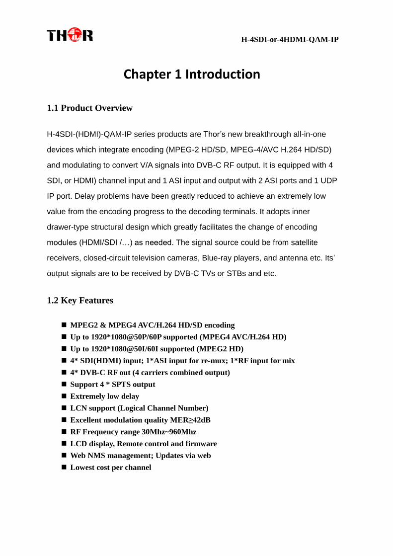
Chapter 1 Introduction
1.1 Product Overview
H-4SDI-(HDMI)-QAM-IP series products are Thor’s new breakthrough all-in-one
devices which integrate encoding (MPEG-2 HD/SD, MPEG-4/AVC H.264 HD/SD)
and modulating to convert V/A signals into DVB-C RF output. It is equipped with 4
SDI, or HDMI) channel input and 1 ASI input and output with 2 ASI ports and 1 UDP
IP port. Delay problems have been greatly reduced to achieve an extremely low
value from the encoding progress to the decoding terminals. It adopts inner
drawer-type structural design which greatly facilitates the change of encoding
modules (HDMI/SDI /…) as needed. The signal source could be from satellite
receivers, closed-circuit television cameras, Blue-ray players, and antenna etc. Its’
output signals are to be received by DVB-C TVs or STBs and etc.
1.2 Key Features
MPEG2 & MPEG4 AVC/H.264 HD/SD encoding
Up to 1920*1080@50P/60P supported (MPEG4 AVC/H.264 HD)
Up to 1920*1080@50I/60I supported (MPEG2 HD)
4* SDI(HDMI) input; 1*ASI input for re-mux; 1*RF input for mix
4* DVB-C RF out (4 carriers combined output)
Support 4 * SPTS output
Extremely low delay
LCN support (Logical Channel Number)
Excellent modulation quality MER≥42dB
RF Frequency range 30Mhz~960Mhz
LCD display, Remote control and firmware
Web NMS management; Updates via web
Lowest cost per channel

H-4SDI-or-4HDMI-QAM-IP
1.3 Specifications
Encoding Section
Video
Encoding MPEG2; MPEG4 AVC/H.264
Input SDI*4
Resolution
1920*1080_60P, 1920*1080_50P, (-for MPEG4 AVC/H.264)
1920*1080_60i, 1920*1080_50i,
1280*720_60p, 1280*720_50P
720*480_60i, 720*576_50i
Audio
encoding MPEG1 Layer II, MPEG2-AAC, MPEG4-AAC
Sample rate 48KHz
Bit rate 64kbps, 96kbps,128kbps, 192kbps, 256kbps, 320kbps
DVB-C Modulator Section
Standard J.83A , J.83B, J.83C
MER ≥42dB
RF frequency 30~960MHz, 1KHz step
Symbol rate 5.000~9.000Msps adjustable
RF output level -30~ -10dbm (81~97 dbµV), 0.1db step
J.83A
Constellation 16/32/64/128/256QAM
bandwidth 8M
J.83B
Constellation 64QAM/ 256QAM
bandwidth 6M
J.83C
Constellation 64QAM/ 256QAM
bandwidth 6M
System
Local interface LCD + control buttons
Remote management Web NMS
output ASI out (BNC type);
4*SPTS out (RJ45, 100M)
NMS interface RJ45, 100M
Language English
General
Power supply AC 100V~240V
Dimensions 482*400*44mm
Weight 5 kgs
Operation temperature 0~45℃

H-4SDI-or-4HDMI-QAM-IP
1.4 Schematic Overview
Inner Construction Overview
The Links between Programs and Carriers

H-4SDI-or-4HDMI-QAM-IP
1.5 Principle Chart
1.6 Typical Application of 4 * Carrier Outputs
As we all know, to guarantee the picture quality of 1920x1080@50I/60I resolution HD
program, the video bit-rate may exceed 10 Mbps, and even reach up to 15Mbps.
However, when the modulating constellation is 64QAM (with 6MHz bandwidth), the
maximum possible bit-rate output for single DVB-C carrier is only around 20Mbps.
15Mbps x4 =60Mbps > 20Mbps.
It means the single DVB-C carrier simply can't carry the 4 channels 1080i HD
program if the average bit-rate exceeds 10Mbps.
That's why we designed 4*DVB-C carrier modulation board which quadruples the
maximum possible bit-rate bandwidth up to 80Mbps and above when 64QAM
constellation is used. This breakthrough makes it possible to reliably carry 4 channels
of MPEG2 HD programs output simultaneously.
Below this chart will help to clearly illustrate the working principle.

H-4SDI-or-4HDMI-QAM-IP
1.7 Appearance and Description
Front Panel Illustration
① LCD window: LCD display
② NMS & DATA ports
③ Power and Alarm Indicators
④ Lock Indicators
⑤ Up and down, left and right button
⑥ Enter button: for confirm

H-4SDI-or-4HDMI-QAM-IP
⑦ Menu button: for back step
⑧ Lock button: press to lock set
Rear Panel Illustration
① SDI(HDMI) Module 1: SDI input port 1&2
② SDI(HDMI) Module 2: SDI input port 3&4
③ RF in port (for combiner use)
④ RF out port
⑤ ASI input port
⑥ ASI output ports
⑦ Switch
⑧ Power supply slot
⑨ Grounding
4 Channel HDMI Version pictured below

H-4SDI-or-4HDMI-QAM-IP
Chapter 2 Installation Guide
Please use caution when operating this device in order to abstain any possible injury
during installation. For this reason, please read all details listed below and make and
use caution before proceeding to operate and use this electronic equipment.
2.1 General Precautions
Must be operated and maintained free of dust or debris.
The cover should be securely fastened, do not open the cover of the products when the
power is on.
After installation, securely stow away all loose cables, external antenna, and others.
2.2 Power Precautions
When you connect the power source, make sure it is grounded correctly so it doesn’t
cause an overload.
Avoid operating on a wet floor in the open. Make sure the extension cable is in good
condition.
Make sure the power switch is off before you start to install the device.
2.3 Device’s Installation Flow Chart Illustrated as following
Connecting
Grouding
Wire and
Power
Cord
Acquisition
Check
Installing
Device
Setting
Parameter
Running
Device
Connecting
Signal
cable

H-4SDI-or-4HDMI-QAM-IP
2.4 Environment Requirement
Item Requirement
Machine Hall
Space
When user installs machine on rack, the distance between 2
rows of machine frames should be 1.2~1.5m and the distance
against wall should be no less than 0.8m.
Machine Hall Floor
Electric Isolation, Dust Free
Volume resistivity of ground anti-static material:
1X10⁷~1X10
10 ,Grounding current limiting resistance: 1M
(Floor bearing should be greater than 450Kg/㎡)
Environment
Temperature
5~40℃(sustainable ),0~45℃(short time),
installing air-conditioning is recommended
Relative Humidity 20%~80% sustainable 10%~90% short time
Pressure 86~105KPa
Door & Window Installing rubber strip for sealing door-gaps and dual level
glasses for window
Wall It can be covered with wallpaper, or brightness less paint.
Fire Protection Fire alarm system and extinguisher
Power
Requiring device power, air-conditioning power and lighting
power are independent to each other. Device power requires
AC 110V±10%, 50/60Hz or AC 220V±10%, 50/60Hz. Please
carefully check before running.
2.5 Grounding Requirement
It is important to keep this device grounded to ensure all of the modules
function correctly. Correctly grounding the device will also help prevent any
electrical interference, lightening. Etc. Also it helps reject minor interference that
may disrupt the devices ability to function smoothly. General rule of them, make
sure the device is grounded when installing anywhere.

H-4SDI-or-4HDMI-QAM-IP
Always use copper wire. When applied correctly the ground must be wrapped
well to ensure maximum conduction so it can reduce any high frequencies. The
copper ground wire should also be as short and thick as possible
Installer must make sure that the two ends of the ground are well conducted
and have appropriate anti-rust properties.
It is prohibited to use any other device as part of the grounding electric
circuit.
The area of the conduction between the ground wire and device’s frame
should be no less than 25 ㎡.
Chapter 3 Operation
3.1 LCD Menus
An overview of the LCD menus:

H-4SDI-or-4HDMI-QAM-IP

H-4SDI-or-4HDMI-QAM-IP
3.2 Initial Status
Switch on the device and after a few seconds’ initialization, it presents start-up pictures as
below:
Start up… Start OK…
Cable A XXX.00MHz
P1:X.XXMbps P2: X.XXMbps

H-4SDI-or-4HDMI-QAM-IP
Cable: indicate the modulation standard of this device is DVB-C.
A: the symbol of different carrier output. “A”, “B”, “C”, and “D” alternate
constantly with the following output frequency.
XXX.XX MHz indicates the current output frequency (range: 30~960MHz) of its
corresponding carrier output.
P1: Program 1; P2: Program 2; P3: Program 3; P4: Program 4
X.XX Mbps: indicate the encoding bit rate of each channel respectively.
3.3 General Settings for Main Menu
Press “Lock” key on the front panel to enter the main menu. The LCD will display the
following pages where user can configure the parameters for the device:
User can press UP/DOWN buttons to specify menu item, and then press ENTER to
enter the submenus as below:
1) Alarm Status
The alarm indicator will turn on if there is no A/V signals inputting or outputting bit
rate overflows. User then can enter this menu to check the error type.
2) Encode Setting
Under this submenu, the LCD will show “2.1 Input 1”, “2.2 Input 2” and “2.3 ASI”.
1 Alarm Status
2 Encode Setting 3 Modulate Setting
4 IP Output Setting
5 Network Setting
6 Saving Config
7 Loading Config
8 Version
2.1 Input 1
2.2 Input 2
2.3 ASI

H-4SDI-or-4HDMI-QAM-IP
Under submenus 2.1 or 2.2, user could set the video encoding format and bit rate, and
set audio encoding bit rate and also read the audio encoding format of the program from
the SDI(HDMI) input.
“Video Format”: the encoding module supports both MPEG2 and MPEG4
AVC/H.264 formats. Move the triangle mark with LEFT/RIGHT keys to specify the
intended format and press ENTER to confirm.
“Video Bit Rate”: Move the underline with LEFT/RIGHT keys and modify the
value of frequency with UP/DOWN keys, and press ENTER key to save the
settings.
“Audio Format”: the encoding module supports MPEG2 audio format. This is a
read-only interface for checking.
“Audio Bit Rate” is to select audio encoding bit rate from the options provided.
Video Bit Rate
08.000 Mbps
Video Format
Video Bit Rate
2.1 Input 1
MPEG2
64 Kbps
96 Kbps
Audio Format
Audio Bit Rate
MPEG2 H.264
2.1.1 Program 1
2.1.2 Program 2

H-4SDI-or-4HDMI-QAM-IP
Under submenu 2.3, user could parse the inputting programs and select the
programs to output.
“Parse Program” is for checking the quantity of input programs from the
corresponding Tuner input.
“Select Program A” is for selecting programs from the ASI IN to output through
Carrier A. Move the triangle mark to specify the program and press RIGHT/LEFT
keys to shift the mark between “√” and “X”. (“√”: to output the corresponding
program; “X”: not to output the corresponding program)
REMARK: “Select Program B/C/D” shares the same explanation with “Select
Program A”.
3) Modulator Setting
When entering “Modulator Setting” submenu, user can find below different
parameters can be set and the LCD window would show as below:
►1 GXTV √
2 SZTV X
Parse Program
Get 3 programs Parse Program
Select Program A
2.3 ASI
Select Program B
Select Program C
Select Program D
3.1 Output A
3.2 Output B
3.3 Output C
3.4 Output D
3.5 ASI Output

H-4SDI-or-4HDMI-QAM-IP
As the H-4SDI-(4HDMI)-QAM-IP (DVB-C Modulating) is with 4 carrier outputs,
“3.1”-“3.4” represent the “Carrier A”, “Carrier B”, “Carrier B”, and “Carrier D”
respectively. User can enter “3.1”/“3.2”/“3.4”/“3.4” to set the corresponding modulating
parameters. Submenus (taking “3.1” as an example) are as below:
Standard
There are three possible options provided for selecting Standard: J.83A (DVB-C), J.83B,
J.83C when the display shows them, user just need swift LEFT and RIGHT key to choose.
Constellation
Three different constellations: J.83A (DVB-C), J.83B, J.83C will show on the LCD
window when Constellation been entered.
J.83A (DVB-C) contains 16QAM, 32QAM, 64QAM, 128QAM, and 256QAM;
J.83B contains 64QAM, 256QAM;
J.83C contains 64QAM, 256QAM.
16QAM: Quadrature Amplitude Modulation is 16
32 QAM: Quadrature Amplitude Modulation is 32
64QAM: Quadrature Amplitude Modulation is 64
128QAM: Quadrature Amplitude Modulation is 128
256QAM: Quadrature Amplitude Modulation is 256
3.1 Output A
3.1.1 Standard
3.1.2 Constellation
3.1.5 RF Out Level
3.1.6 RF On
3.1.3 Symbol Rate
3.1.4 RF Frequency

H-4SDI-or-4HDMI-QAM-IP
Setting method is just the same. When the display shows them, user just need swift LEFT
and RIGHT key to choose and repressing “ENTER” for confirm.
Symbol Rate
The symbol rate range of both J.83A (DVB-C) & J.83C is 5Msps to 9Msps and J.83B is
fixed and cannot be changed.
RF Frequency
The RF output frequency range is from 30 to 960MHz with 1K stepping. After entering the
RF frequency setting submenu, users the can press LEFT, RIGHT, UP, and DOWN buttons
to adjust the frequency and confirm by press ENTER button.
RF out level
The RF attenuation range is from -30~-10dbm (81~97dbµV) with 0.1db step. After
entering this setting submenu, user can shift UP/DOWN/LEFT/RIGHT key to set the
output level and press ENTER to confirm.
RF On
This interface is to decide whether to enable the RF (carrier A) output or not.
OFF: to disable programs to output through carrier A.
ON: to enable programs to output through carrier A.
NOTE: The setting principle of “3.2”, “3.3”, and “3.4” are the same with “3.1” explained above.
ASI Output:
RF Frequency
750.000 MHz
RF On
Off On
RF Out Level
-10.0 dbm

H-4SDI-or-4HDMI-QAM-IP
H-4SDI-QAM-IP encoder & modulator (DVB-C Modulating) is with quad-carrier output:
Output A, B, C, and D.
Output A: the ASI output programs are same as carrier output A.
Output B: the ASI output programs are same as carrier output B.
Output C: the ASI output programs are same as carrier output C.
Output D: the ASI output programs are same as carrier output D.
4) IP Output Setting
H-4SDI-(4HDMI)-QAM-IP encoder & modulator (DVB-C Modulating) is with
quad-carrier output (Output A, B, C, and D), “4.1” to “4.4” are for the settings of the 4
carrier outputs respectively. Submenus go as 4.1.1-4.1.7
User can enter 4.1.1 to decide whether to turn the IP port on or off, and enter to the
rest menu items to set the corresponding parameters.
4.1.1 IP Output
4.1.2 Service IP
4.1.3 Output IP
4.1.4 Subnet Mask
4.1.5 Gateway
4.1.6 Port
ASI Output A B C D
4.1 IP Output A
4.2 IP Output B
4.3 IP Output C
4.4 IP Output D
4.1.7 Flt Null Pkt
Output IP
224.002.002.002
Subnet mask
255.255.255.000
Gateway
192.168.002.000
Port
01234
IP Output
OFF ON Service IP
192.168.002.137
Filter Null Packet
OFF ON

H-4SDI-or-4HDMI-QAM-IP
5) Network setting
After enter Network Setting, there are three submenus shows as the following LCD
displays.
User can press “UP/DOWN” to choose this item and “ENTER” & “LEFT/RIGHT” to
set the parameters.
NOTE: The MAC address is according to the factory setting, and it is unique.
6) Saving Configuration
Users can enter Saving Configuration submenu for saving settings. Choose yes and
press ENTER to confirm.
7) Loading Configuration
At this menu, user can press UP/DWON key to select and repress ENTER to confirm.
5.5 Reset Password
5.6 Web Manage Port
5.3 Gateway
5.4 MAC Address
IP Address
192.168.000.136
Subnet Mask
255.255.255.000
Gateway
192.168.000.001
MAC Address
ffffffffffffffffffffff
Reset Password?
Yes NO
5.1 IP Address
5.2 Subnet Mask
Save Configuration?
Yes No
Saving Config…
Web Manage Port
00080

H-4SDI-or-4HDMI-QAM-IP
User can restore the device into the last saved configuration by choosing “7.1” and
restore the device into factory configuration by choosing “7.2” the display will show
as below:
8) Version
User can check the software version and hardware version of this equipment under
this submenu.
Load Saved CFG?
Yes No Loading Config…
7.1 Load Saved CFG
7.2 Load Default
Encoder Modulator
SW 1.00 HW 0.3

H-4SDI-or-4HDMI-QAM-IP
Chapter 4 WEB NMS Operation
User not only can use front buttons to set configuration, but also can control and set
the configuration in computer by connecting the device to web NMS Port. User
should ensure that the computer’s IP address is different from the H-4SDI-QAM-IP
IP address; otherwise, it would cause IP conflict.
4.1 login
The default IP address of this device is 192.168.0.136. (We can modify the IP
through the front panel.)
Connect the PC (Personal Computer) and the device with net cable, and use ping
command to confirm they are on the same network segment.
I.G. the PC IP address is 192.168.99.252, we then change the device IP to
192.168.99.xxx (xxx can be 0 to 255 except 252 to avoid IP conflict).
Use web browser to connect the device with PC by inputting the Encoder &
Modulator’s IP address in the browser’s address bar and press Enter.
It will display the Login interface as Figure-1. Input the Username and Password
(Both the default Username and Password are “admin”.) and then click “LOGIN” to
start the device setting.
Figure-1
H-4SDI-or-4HDMI-QAM-IP
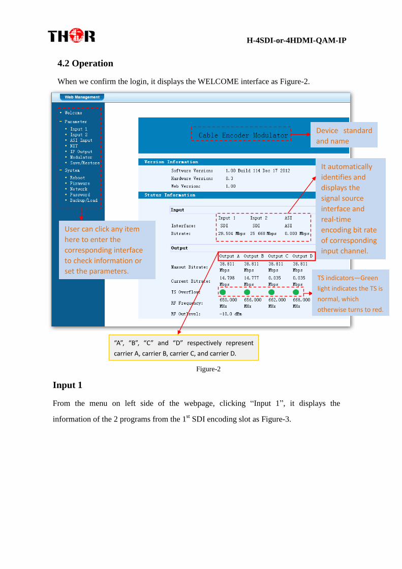
4.2 Operation
When we confirm the login, it displays the WELCOME interface as Figure-2.
Figure-2
Input 1
From the menu on left side of the webpage, clicking “Input 1”, it displays the
information of the 2 programs from the 1st SDI encoding slot as Figure-3.
Device standard
and name
User can click any item
here to enter the
corresponding interface
to check information or
set the parameters.
It automatically
identifies and
displays the
signal source
interface and
real-time
encoding bit rate
of corresponding
input channel.
TS indicators—Green
light indicates the TS is
normal, which
otherwise turns to red.
“A”, “B”, “C” and “D” respectively represent
carrier A, carrier B, carrier C, and carrier D.

H-4SDI-or-4HDMI-QAM-IP
Figure-3
Enable or Disable the Carrier Output Function:
…..………………………………..... NOTE ……..……..………………………….
The different combination of Video Format, Video Bit-rate, Low Delay Mode and the
Resolution of signal source will have an impact on the delay. Please refer to the Appendix
attached for detailed information.
…………………………………………………………………………………………..……
The 4 boxes respectively represent Carrier A, B, C, and D. Tick the corresponding box(es)
to enable the related program output through the corresponding Carrier.
One program can output through a single or multiple Carriers. However, it is suggested
that a single carrier outputs only one program to adapt the fluctuant encoding bit rate.
Encoding Status—Green
light indicate it works
normally, which
otherwise turn to red.
This column is for setting
the 1st SDI IN program.
This column is for setting
the 2ed SDI IN program.
General
Settings for
the SDI IN
programs:
User can edit
any item listed
as needed.

H-4SDI-or-4HDMI-QAM-IP
For user to reference detailed explanation of terms on this interface
Click this button to apply the default setting of Input 1
Click this button to apply the modified parameters.
Input 2
Similarly, from the menu on left side of the webpage, clicking “Input 2”, it displays
the information of the 2 programs from the 2ed
SDI encoding slot.
ASI Input
Click “ASI Input”, it will display ASI input program information as Figure-4.
Figure-4
Select the carrier output channel for the multiplexed programs.
If this item is selected, all the input programs will pass through
without any elimination.
Selecting this item to allow user select programs as required to
output.
Click “Refresh Input” to refresh the input program list.

H-4SDI-or-4HDMI-QAM-IP
Click “Refresh Output” to refresh the output program list.
When user checks one input program with “√”, one can transfer the
checked program to the right box to output.
Here user can select the programs which we want to output or we can output all the
programs.
Similarly, user can cancel the multiplexed programs from the right
box.
& to select all the input/output programs with
one-time clicking.
Time limitation to parse the input programs
Click this button to trigger a dialog box as below, where to add the
PIDs which need pass through.
In some occasions, there are some PIDs which won’t belong to any program, such as
EPG, NIT tables and so on which user just wants to pass them through the
multiplexing module without changing anything. This is the main purpose of this
function.
Click “Add” to add more boxes for filling the Input & Output PIDs, then click
“Apply” to confirm.

H-4SDI-or-4HDMI-QAM-IP
NIT Table setting
Click “NIT” from the menu to trigger the screen as Figure-5. Then click “Add”
from this screen to add the program descriptor in NIT Table.
Figure-5
Select the carrier output channel for the inserted NIT.
Click “Add” from this page, it will display the screen as Figure-6 where it
requires to add Service ID and configure other parameters for the programs.
Figure-6
Here by clicking “Add”, users can set the program LCN in its respective

H-4SDI-or-4HDMI-QAM-IP
field. After setting all the data, users need to click on “Save” to save the
setting. As Figure-7, click “Update NIT” to update the NIT
information.
Figure-7
IP Output
Click “IP Output” from the left menu, it will display the screen as Figure-8 where to
set the multicast IP Output address for the device if needed and set the IP output for
the programs.
After setting the parameters, click “Apply” to save the setting.
Figure-8
The 4 boxes represent the 4
SPTS out respectively.
To configure the
output IP address
and ports for the 4
SPTS respectively.

H-4SDI-or-4HDMI-QAM-IP
Modulator Setting
Enter in “Modulator” and it will display the Modulator Configuration screen as
Figure-9 where can set modulation parameters.
RF On –To decide whether to enable the RF (carrier A/B/C/D) output or not.
Standard –Modulating standard selecting.
Constellation –QAM type selecting.
Symbol Rate – To set the symbol rate
RF Frequency A/B/C/D– to set the RF frequency for the 4 carriers
RF Out level –to set the RF output level
ASI Output– To select carrier output channel for ASI output (Output A: The ASI
output programs are same as carrier A; Output B: The ASI output programs are
same as carrier B; and the like.)
After setting all the parameters, click “Apply” to save the Modulator
Configuration.
Figure-9
Save/Restore
Clicking “Save/Restore” from the menu, it will display the screen as Figure-10 where
can save the configuration permanently to the device. Click “Save Configuration”,

H-4SDI-or-4HDMI-QAM-IP
for store the data permanently to the device.
By using “Restore Configuration” user can restore the latest saved configuration to
the device.
By using “Factory Set” user can import the default factory configuration.
Figure-10
Restart the Device
Click “Reboot” from the menu, the screen will display as Figure-11. Here when
clicking “Reboot” box, it will restart the device automatically.
Figure-11
Update the Device

H-4SDI-or-4HDMI-QAM-IP
Click “Firmware” from the menu it will display the screen as Figure-12. Here user
can update the device by using the update file.
Click “Browse” to find the path of the device update file for this device then click
“Update” to update the device.
After updating the device, user needs to restart the device by using Reboot option.
Figure-12
Network
When user clicks “Network”, it will display the screen as Figure-13. It displays the
network information of the device. Here user can change the device network
configuration as needed.
Browse
Button

H-4SDI-or-4HDMI-QAM-IP
Figure-13
Change Password
When user clicks “Password”, it will display the password screen as Figure-14.
Here user can change the Username and Password for login to the device.
After putting the current and new Username and Password, click Apply” to save the
configuration.
Figure-14

H-4SDI-or-4HDMI-QAM-IP
Keyboard and LCD Lock: If it is marked with “√”,the LCD and keyboard will be
locked to avoid unrelated users’ modifying or view the device information and
configurations. User can’t operate the keyboard & LCD while only the device IP
address can be noted in the LCD window.
Backup/Load
Click “Backup/Load” from the menu, it will display the screen as Figure-15.
Backup Configuration – To back up the device configuration file to a folder
Load Configuration – If user needs to load the old configuration to the device, click
“Browse” and find the backup configuration file path. After selecting the file, click
“Load File” to load the backup file to the device.
Figure-15
Browse
Button
IP Address
192.168.000.136

H-4SDI-or-4HDMI-QAM-IP
Chapter 5 Troubleshooting
Thor Broadcast has every device go through several levels of inspection for quality
control. All systems shipped by Thor Broadcast are fully tested and visually inspected
after manufacture. Additionally, all units are re-inspected and pre-configured prior to
shipping. Under most circumstances, Thor offers free configuration service for most
equipment. Thor can set operating parameters prior to shipping, and ensure trouble
free operation and installation.
Prevention Measure
Please ensure that the environment remains within 0 to 45 °C
Provide adequate ventilation to the heat sinks and side vents
Check the input AC voltage, please use appropriate power supplies
Check the RF output level, make sure it varies within a tolerable range if necessary
Check that all signal cables are securely installed and nothing is loose
Frequently switching on/off device is prohibited; please allow at least 10 seconds before
switching system on and off.
Conditions need to unplug power cord
Power cord or socket damaged.
Any liquid that got into the device.
Any stuff that could cause a circuit short
Device is in damp environment
Device has suffered from physical damage; i.e. it fell off a rack
Longtime idle.
After switching on and restoring to factory setting, device still won’t work properly.
Maintenance needed on device

H-4SDI-or-4HDMI-QAM-IP
Chapter 6 Application
Application Examples
1). Residences and Private Homes Video content DVB‐T/ISDB-T distribution
2) Outside Audio‐ Video contents ON‐ AIR DVB‐ T/ISDB-T distribution
3) Hotel Audio‐ Video contents DVB‐ T/ISDB-T distribution

H-4SDI-or-4HDMI-QAM-IP
4) Bar Audio‐ Video contents distribution
5) Cinema Audio‐ Video contents DVB‐ T/ISDB-T distribution
6) Company Audio‐ Video contents distribution

H-4SDI-or-4HDMI-QAM-IP
Chapter 7 Packing List
H-4SDI(4HDMI)-QAM-IP Encoder/Modulator
1PC
User's Manual 1PC
SDI Cables 4PCs
Power Cord 1PC

H-4SDI-or-4HDMI-QAM-IP
APPENDIX
INTERNAL TEST REPORT OF DELAY
(The values of average delay cover the progress from Encoding
to Decoding.)
Decoding
Terminal
Encoding Details Average
Delay
(ms) Resolution
Encoding
Bit Rate
DTS
Mode
Single
Source
Interface
Video
Format
DVB-C HD
STB 1080i@50 14M
DTS=1
(Mode 1)
HDMI mpeg2 170
H.264 347.5
SDI mpeg2 227.5
H.264 367.5
DTS=40
(Mode 2)
HDMI mpeg2 222.5
H.264 395
SDI mpeg2 240
H.264 397.5
DVB-C HD
STB 720p@50 14M
DTS=1
(Mode 1)
HDMI mpeg2 85.75
H.264 237.5
SDI mpeg2 127.5
H.264 295
DTS=40
(Mode 2)
HDMI mpeg2 182.5
H.264 277.5
SDI mpeg2 167.5
H.264 325
DVB-C HD
STB 576i@50 14M
DTS=1
(Mode 1)
HDMI mpeg2 310
H.264 600
SDI mpeg2 330
H.264 620
DTS=40
(Mode 2)
HDMI mpeg2 270
H.264 610
SDI mpeg2 280
H.264 620

H-4SDI-or-4HDMI-QAM-IP