Embed Size (px)
Citation preview
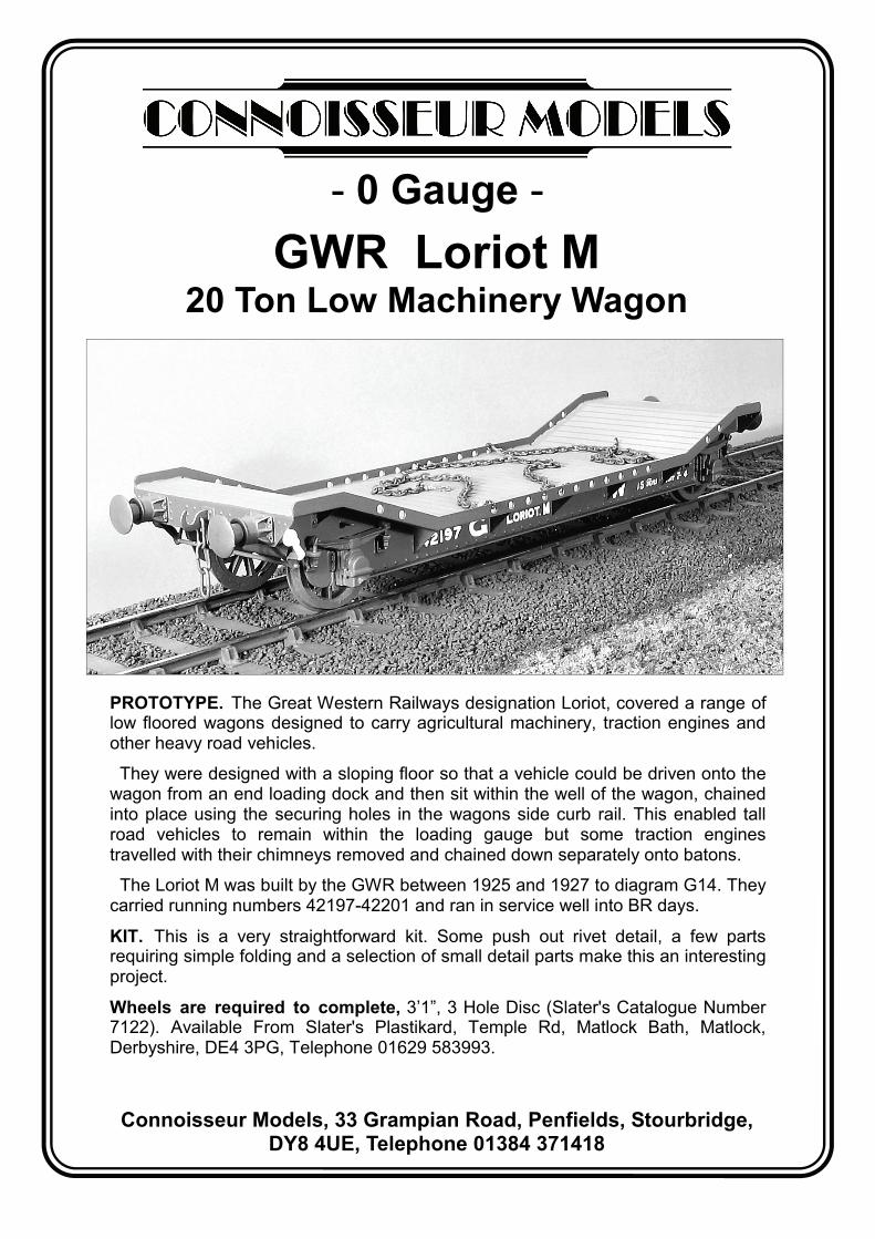
PROTOTYPE. The Great Western Railways designation Loriot, covered a range of low floored wagons designed to carry agricultural machinery, traction engines and other heavy road vehicles.
They were designed with a sloping floor so that a vehicle could be driven onto the wagon from an end loading dock and then sit within the well of the wagon, chained into place using the securing holes in the wagons side curb rail. This enabled tall road vehicles to remain within the loading gauge but some traction engines travelled with their chimneys removed and chained down separately onto batons.
The Loriot M was built by the GWR between 1925 and 1927 to diagram G14. They carried running numbers 42197-42201 and ran in service well into BR days.
KIT. This is a very straightforward kit. Some push out rivet detail, a few parts requiring simple folding and a selection of small detail parts make this an interesting project.
Wheels are required to complete, 3’1”, 3 Hole Disc (Slater's Catalogue Number 7122). Available From Slater's Plastikard, Temple Rd, Matlock Bath, Matlock, Derbyshire, DE4 3PG, Telephone 01629 583993.
Connoisseur Models, 33 Grampian Road, Penfields, Stourbridge, DY8 4UE, Telephone 01384 371418
GWR Loriot M 20 Ton Low Machinery Wagon
- 0 Gauge -

GENERAL INSTRUCTIONS
Please read this section carefully, especially if this is your first etched brass kit. Many modellers fight shy of working in this medium, but the basic skills are relatively easy to acquire. Once you’ve learned how to form and solder brass, you’ll find all kinds of modelling possibilities will open up for you.
Assembling an etched kit involves exactly the same skills that a scratchbuilder uses – the only difference is that the cutting out of the parts is already done for you. Some filing and trimming will, however, be necessary from time to time. Where this is the case, I have highlighted it in the instructions.
The main skill to master is soldering and I would recommend a Weller 40 Watt soldering iron. This has a 6mm diameter, removable copper bit. The bit is shaped like a screwdriver and has a bright coating of solder (tinned). This combination of iron and bit shape is ideal for running fillet joints and has a good reserve of heat, that is necessary for soldering small parts on to large components. Note the shape and condition of a new bit, as this won’t last long and will need restoring back to this condition.
It is important to keep the bit clean and in good condition as you work. Get a soldering iron stand containing a damp sponge; old oxidized solder is wiped off on this before picking up fresh solder for each joint. If you haven’t made a joint for some time you may find that a hard black crust has formed on the bit. Remove this with a brass wire brush (suede brush) and then feed some multicore solder onto each side of the bit to restore a bright surface (referred to as wetting or tinning the bit). After about 8 hours use you will find the bit is in poor condition, with holes and a ragged edge. File the bit back to its original shape using a hand bastard file and then polish the surfaces on emery cloth. Coat the bit with Fluxite Soldering Paste (traditionally used by plumbers) and this will prevent the bare copper oxidizing as the iron heats up. Then feed multicore solder onto the bit to form a generous coating and leave to bubble away for a couple of minutes before wiping excess off to give a bit almost as good as new.
A smaller Antex 25 Watt iron with a 3.2mm screwdriver bit is very useful for small assemblies and detail work such as handrails, but will have insufficient heat reserve for main assembly work. The Antex has a plated iron bit, after a little use with 145° solder a grey oxide appears on the bit that will prevent you from picking up the solder. Touch the bit to some multicore solder and it will flash over the bit, wetting it so that you can continue picking up 145° solder. I have found no problems with mixing the two solders in this way.
I use 145° solder for virtually all assembly work. I prefer it in wire form but it is also produced in stick form by Carrs. I find that its lower working temperature helps to give a quick clean joint. Limiting the build up of heat in components, which may cause distortion. I find that I can hold parts together with my finger ends and make a joint before heat reaches my fingers or other etched parts drop off.
I use 60/40, tin/lead, fluxed multicore electrical solder (melting point about 190°) mainly to keep the iron bits in good condition. As it gives a slightly stronger joint than 145° I sometimes use it for small spot joints on handrail wire, lamp brackets etc, but still use extra liquid flux.
For all brass and nickel silver work I use Carrs green label liquid flux. You will soon get the feel for how much to use but more problems are caused by too little flux than too much.
Before soldering components together, thoroughly clean both surfaces along the join line with a glass fibre burnishing brush. Using your tweezers or a knife blade etc, hold the parts together in the correct position and, with an old paintbrush, run some flux along the area to be joined. Still keeping the parts correctly aligned, pick up a small quantity of solder on the tip of your iron and carry it to the joint (unlike electrical soldering, when you feed solder into the joint). Hold the iron against the joint just long enough for the solder to flash between the parts. Don’t let go of the parts until the solder has cooled – this takes from five to ten seconds. To run a fillet of solder along a joint, wait until the solder flashes between the parts and then pull the molten solder along
Page 2

the joint with the iron tip. Don’t load the iron tip with a lot of extra solder, but work the joint in 1” lengths, bringing in small quantities of solder. Brass is a very forgiving material and if you get something out of alignment, use heat from the iron to desolder the joint before starting again. For complicated assemblies, it is a good idea to only tack solder parts together. You can then make adjustments by desoldering until you are happy with the location of parts and then solder solid.
When you need to laminate two or more layers of brass together, align the parts and carefully clamp them together, either in the vice or by holding them with miniature crocodile clips. Run flux around the edges, and then go around with the soldering iron. Clean up thoroughly afterwards.
To fit small parts and overlays on to a larger assembly, such as strapping to a wagon side, when you need to prevent finely detailed areas such as planking becoming clogged up with solder. Tin the back of the small component first, then hold in place on the model and apply flux. Carefully wipe the tip of your iron on a sponge to remove any solder from it (dry iron), and then touch it against the parts to be joined. After a few seconds you’ll see molten solder bubbling from the edges. Remove the iron, still holding the parts in place, and allow the joint to cool. An alternative is to use solder paint (I would recommend Carrs 188 solder paste). As the name suggests, this is a flux and solder in one. Simply apply a thin coat of solder paint to the back of the component instead of tinning. Still apply a small amount of liquid flux before you solder the part into place.
Any surplus solder should be removed using a craft knife, I find No 10 curved scalpel blades ideal, then burnish clean with a glass fibre brush. With practice, you’ll learn how to use the minimum amount of solder to do the job. Flux is corrosive so, after each soldering session, give your model a good scrub with washing up liquid or Jif. After a day or two, any remaining flux residues will show as a green film, which should be washed away.
To cut parts from the fret, use a sharp Stanley knife on a piece of hardboard or a pointed scalpel blade on a block of softwood. Remove tags and burrs with a fine file.
Three-dimensional parts are formed by folding. On an etched brass kit, the fold lines are normally half-etched on the inside of the fold. You’ll be able to fold most parts using smooth-jawed pliers. For longer parts folding bars are desirable.
Other useful tools include a bench vice, a good pair of tweezers, a set of Swiss files (get a full set of cheap ones and then buy quality replacements for the three that you use the most), a pin vice with a selection of drills from 0.5mm to 2.1mm plus a few larger sizes that you use regularly (2.6mm for axle bearings etc), some square-nosed pliers and some very pointed-nosed ones, preferably with smooth jaws. Buy cheap tools first and duplicate the most used ones with quality.
Try to complete all high-temperature soldering before attaching any of the cast whitemetal parts. These can be attached with two-part epoxy resin such as Devcon or Araldite Rapid. Ensure the surfaces to be glued are clean and free of grease.
A better alternative is to solder your white metal castings using Carrs 70 degree low melt solder and Carrs red label white metal flux. The iron should be run at a much lower heat so that you do not melt the castings. I have a domestic light dimmer switch and plug socket fixed to a piece of wood, wired up with a lead and 3 amp mains plug to the input side of the dimmer switch and the output of the dimmer switch into the plug socket (remember to continue the earth). Plug your 40 Watt iron (25 Watt iron won’t work) with a clean and freshly tinned bit into this and experiment with adjusting the switch until you find the range of temperature at which the solder melts, but a scrap casting does not. Note as the iron is running at a lower voltage it will take longer to heat up, so when you think the adjustment is correct do check a few minutes later on another scrap casting to see that it doesn't melt. Then scribe a mark on the switch knob to indicate this position.
When attaching white metal fittings to brass the surface of the brass must be tinned with 145° solder, to allow the solder to grip. The surface of the casting at the joint should be burnished bright. The casting can then be soldered into place with 70° solder and fillets of solder run into any gaps with no risk of melting the casting.
Page 3

Page 4
GW
R L
orio
t M 2
0 To
n Lo
w M
achi
nery
Wag
on
Sta
ndar
d B
R
Live
ry,
grey
si
de
curb
ra
il an
d bl
ack
side
fram
es.
Lette
ring,
w
hite
on
bl
ack
patc
hes
and
num
ber
prec
eded
by
W
. Le
tterin
g w
as p
ositi
oned
, LO
WM
AC
WM
, top
L/H
. Num
ber W
4219
7, L
/H
in w
ell.
20 T
ons
Tare
9-1
2, R
/H in
wel
l. W
B 21
-0, t
op R
/H.
HM
RS
Tra
nsfe
r sh
eet 2
5 B
R r
even
ue w
agon
s. A
lso
avai
labl
e fo
r B
R
liver
y ar
e w
ater
slid
e tra
nsfe
rs f
rom
, Fo
x Tr
ansf
ers,
138
Mai
n S
treet
, M
arkf
ield
, Le
ices
ters
hire
, LE
67 9
UX
. Te
l 01
530
2428
01.
They
als
o pr
oduc
e tra
nsfe
rs fo
r the
bla
ck p
atch
es o
nto
whi
ch th
e le
tterin
g ca
n be
bu
ilt u
p.
For
mor
e in
form
atio
n an
d ph
otog
raph
s of
the
prot
otyp
e w
agon
I w
ould
re
com
men
d, G
WR
Goo
ds W
agon
s, A
tkin
s B
eard
& T
ourr
et,
Tour
ret
Pub
lishi
ng, I
SB
N 0
-905
878-
07-8
. Get
it fr
om y
our
loca
l lib
rary
via
thei
r bo
ok o
rder
sys
tem
. The
G14
Lor
iot i
s fe
atur
ed o
n pa
ge 1
52.
The
Lor
iot
M’s
to
diag
ram
G14
wer
e bu
ilt b
y th
e G
WR
bet
wee
n 19
25 a
nd 1
927
and
they
ran
in
serv
ice
wel
l in
to B
R d
ays.
The
y ca
rried
runn
ing
num
bers
421
97-4
2201
. G
WR
Liv
ery,
All
over
GW
R w
agon
gre
y (R
ailm
atch
ena
mel
spr
ay
No
1604
). P
lank
ed fl
oor,
dirty
woo
d (H
umbr
ol e
nam
el N
o 11
0 w
ith
smal
l am
ount
s of
a li
ght
grey
No
64 a
nd g
unm
etal
No
53 o
r m
att
blac
k N
o 33
Stre
aked
and
ble
nded
in to
rep
rese
nt th
e di
rect
ion
of
the
woo
d gr
ain.
W
hite
end
to b
rake
leve
r. Le
tterin
g, w
hite
(w
eigh
t sh
ould
be
20 T
ons
Tare
9-1
2).
Tran
sfer
s fo
r le
tterin
g ar
e av
aila
ble
from
, H
isto
rical
Mod
el R
ailw
ay
Soc
iety
, B
rian
Web
b (v
olun
teer
sal
es
offic
er),
8 G
ilpin
Gre
en,
Har
pend
en,
Her
ts A
L5 5
NR
. S
end
SA
E f
or li
st a
nd o
rder
for
m o
r th
ey a
re s
tock
ed b
y so
me
spec
ialis
t re
taile
rs.
Thes
e ar
e P
ress
fix
type
and
you
will
requ
ire s
heet
11
GW
R g
oods
veh
icle
insi
gnia
.
Cas
ting
Iden
tific
atio
n an
d Pa
rts
Che
ck L
ist
1 X
6” l
engt
h of
0.9
mm
bra
ss w
ire (f
or b
rake
cro
ss s
haft)
. 1 X
6” o
f spr
ing
stee
l Wire
(for
buf
fer s
prin
ging
, may
be
tarn
ishe
d).
4 X
End
La
shin
g R
ings
Whe
n I m
ade
the
cent
rifug
al m
ould
to p
rodu
ce a
full
set o
f cas
tings
for t
his
wag
on (o
ne m
ould
two
spin
s) I
took
a b
aker
s do
zen
appr
oach
to th
e nu
mbe
r of s
ub m
aste
rs
I pla
ced
in th
e m
ould
. So
you
shou
ld fi
nd e
xtra
cas
tings
to g
uard
aga
inst
acc
iden
ts &
mis
haps
but
the
quan
titie
s lis
ted
are
the
min
imum
requ
ired
for t
he w
agon
.
6 X
Cou
plin
g lin
ks
4 X
Buf
fer B
odie
s 4 X
Buf
fer H
eads
4 X
Buf
fer
Ret
aini
ng C
olla
rs
4 X
Axl
e B
oxes
Bra
ke B
lock
s 2
X L
ong
2 X
Sho
rt 2
X B
rake
Yok
es
Page 5
GW
R L
orio
t M
20 T
on
Low
Mac
hine
ry W
agon
M
ain
Ass
embl
y
Spr
ing
Stee
l Wire
S
olde
r Ret
aini
ng
Col
lar
Buf
fer A
ssem
bly

Page 6
GWR Loriot M Suggested Assembly Order
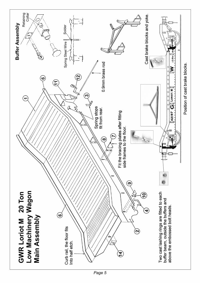
1. Remove from the fret the floor, part 1, and emboss the bolt heads onto the buffer beam. I designed these to be embossed using a scriber, with the point rounded off slightly on an oilstone. Place the part face down onto a block of softwood and press firmly down into the half etched hole. This may slightly distort the buffer beam, so once all bolt heads are embossed, gently correct this by bending back with finger and thumb pressure. If you have a rivet-forming tool, particularly the drop weight type, you may find that the half etched holes are too large for this to work properly. You may be better pushing the spike into the hole with finger pressure, rather than using the drop weight.
Fold the buffer beams and floor; use a side frame as a guide to form these folds at the correct angles. The buffer beam fold is 90° with the bend line on the underside. The main floor bend lines are actually the plank joints and I have marked them with small etched notches, but offer up the side frame to double check that you will be folding at the correct plank joint. Ideally these folds are made with bending bars but you can get away with using two square cornered blocks of softwood (off cuts of 2”x1” etc). Place the floor on top of one block, with the plank line level with the edge of the block. Place the second block on to the floor, again with its edge level with the plank line and put pressure on the blocks with your finger ends. Now lay a steel rule with its edge level with the other side of the plank line, onto the part of the floor that requires folding. Press down on the rule with your finger ends to form the fold (or with the rule on the underside pull upwards if you want the fold the other way). The steel rule will help to transfer your finger pressure evenly, to give a sharp fold at the correct plank line without rippling the adjacent planks. Any slight distortion can be corrected with gentle finger and thumb pressure.
2. Fold through 90°, the bottom angle of the side frames, parts 2. Again ideally using bending bars but you can get away with using the jaws of a vice. If using your vice, you may find it helpful to deepen (but don’t widen) the fold line with a sharp triangular file. Push it up the fold line so that it gouges out the brass until a faint witness mark appears on the other side. This will reduce the amount of pressure required to make the fold. Clamp one end of the bottom angle in the vice jaws and pull the side frame forward to form about 30° of the fold. Work your way along the side frame with the vice jaws slightly overlapping their previous position so that they will flatten any distortion. When you reach the other end, work back forming 60° of the fold and then the final 90°.
GWR Loriot M Etched Parts Identification
1
2 5
6
14 2 13
12 5 4 11 10 8
9
7
9 3
3
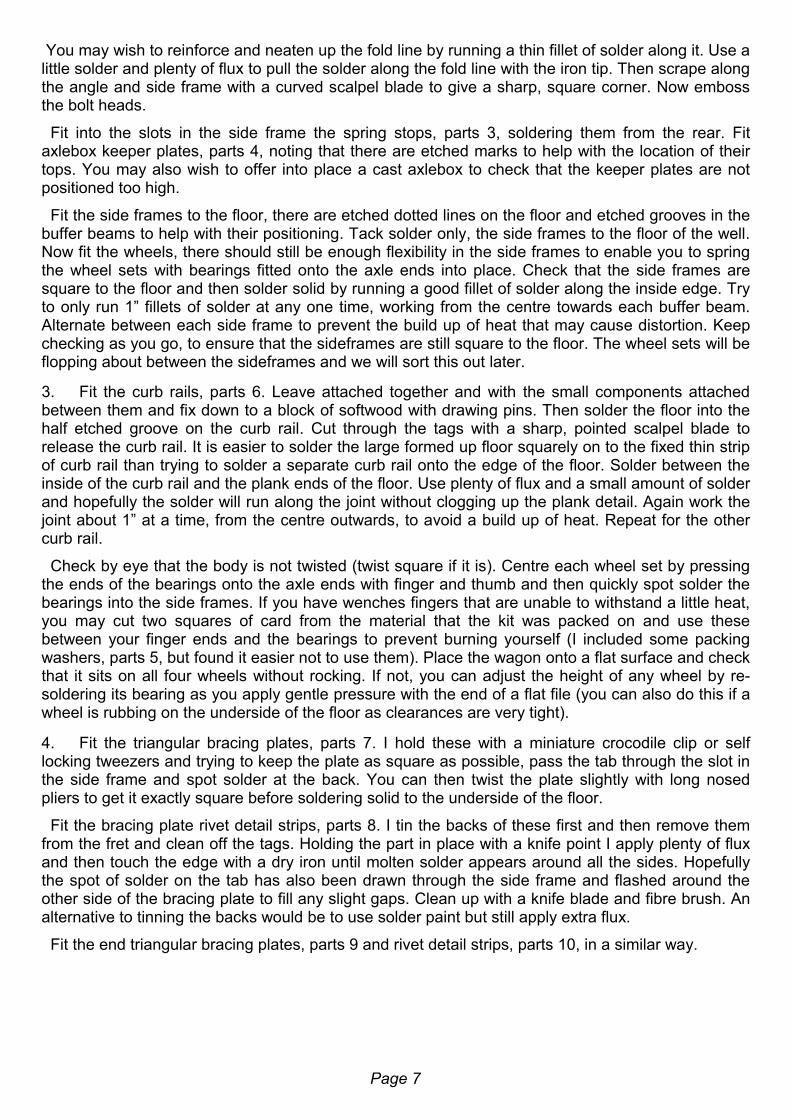
You may wish to reinforce and neaten up the fold line by running a thin fillet of solder along it. Use a little solder and plenty of flux to pull the solder along the fold line with the iron tip. Then scrape along the angle and side frame with a curved scalpel blade to give a sharp, square corner. Now emboss the bolt heads.
Fit into the slots in the side frame the spring stops, parts 3, soldering them from the rear. Fit axlebox keeper plates, parts 4, noting that there are etched marks to help with the location of their tops. You may also wish to offer into place a cast axlebox to check that the keeper plates are not positioned too high.
Fit the side frames to the floor, there are etched dotted lines on the floor and etched grooves in the buffer beams to help with their positioning. Tack solder only, the side frames to the floor of the well. Now fit the wheels, there should still be enough flexibility in the side frames to enable you to spring the wheel sets with bearings fitted onto the axle ends into place. Check that the side frames are square to the floor and then solder solid by running a good fillet of solder along the inside edge. Try to only run 1” fillets of solder at any one time, working from the centre towards each buffer beam. Alternate between each side frame to prevent the build up of heat that may cause distortion. Keep checking as you go, to ensure that the sideframes are still square to the floor. The wheel sets will be flopping about between the sideframes and we will sort this out later.
3. Fit the curb rails, parts 6. Leave attached together and with the small components attached between them and fix down to a block of softwood with drawing pins. Then solder the floor into the half etched groove on the curb rail. Cut through the tags with a sharp, pointed scalpel blade to release the curb rail. It is easier to solder the large formed up floor squarely on to the fixed thin strip of curb rail than trying to solder a separate curb rail onto the edge of the floor. Solder between the inside of the curb rail and the plank ends of the floor. Use plenty of flux and a small amount of solder and hopefully the solder will run along the joint without clogging up the plank detail. Again work the joint about 1” at a time, from the centre outwards, to avoid a build up of heat. Repeat for the other curb rail.
Check by eye that the body is not twisted (twist square if it is). Centre each wheel set by pressing the ends of the bearings onto the axle ends with finger and thumb and then quickly spot solder the bearings into the side frames. If you have wenches fingers that are unable to withstand a little heat, you may cut two squares of card from the material that the kit was packed on and use these between your finger ends and the bearings to prevent burning yourself (I included some packing washers, parts 5, but found it easier not to use them). Place the wagon onto a flat surface and check that it sits on all four wheels without rocking. If not, you can adjust the height of any wheel by re-soldering its bearing as you apply gentle pressure with the end of a flat file (you can also do this if a wheel is rubbing on the underside of the floor as clearances are very tight).
Page 7
4. Fit the triangular bracing plates, parts 7. I hold these with a miniature crocodile clip or self locking tweezers and trying to keep the plate as square as possible, pass the tab through the slot in the side frame and spot solder at the back. You can then twist the plate slightly with long nosed pliers to get it exactly square before soldering solid to the underside of the floor.
Fit the bracing plate rivet detail strips, parts 8. I tin the backs of these first and then remove them from the fret and clean off the tags. Holding the part in place with a knife point I apply plenty of flux and then touch the edge with a dry iron until molten solder appears around all the sides. Hopefully the spot of solder on the tab has also been drawn through the side frame and flashed around the other side of the bracing plate to fill any slight gaps. Clean up with a knife blade and fibre brush. An alternative to tinning the backs would be to use solder paint but still apply extra flux.
Fit the end triangular bracing plates, parts 9 and rivet detail strips, parts 10, in a similar way.

5. Fit behind the side frames and at one end only, the brake lever brackets (V hangers), parts 11. You may find it helpful, especially if fitting sprung buffers, to file a little extra clearance into the cut out. Then fit through the holes in the brackets a length of 0.9mm brass rod with the ends projecting 2mm from each bracket. Using long-nosed pliers, fold up the brake levers, parts 12, folding the ends around to form a handle with the circular shield behind. Solder the levers to the projecting ends of the brass rod. If you wish to fit sprung buffers, it is better to fit them and the couplings before fitting the rod and brake levers, as this will make access easier.
6. Make up the coupling links and fit them into the coupling hooks, parts 13. I close up the links by holding the curved end in the jaws of a pair of round-nosed pliers in one hand and squeeze the flat parts of the link parallel with long-nosed pliers (angled long-nosed pliers with serrated jaws are even better) held in the other hand. When I have six even-shaped closed links, I open each one slightly with long-nosed pliers and thread three together. The last link passes through the hole in the coupling hook. I reinforce the joint of each link with a spot of 60/40 solder.
Tin the backs of the coupling plates, parts 14. Pass the shank of the coupling hook through the slot in the plate and into the slot in the buffer beam. Using plenty of flux and only a little solder on the iron tip (make sure the coupling links are out of the way) touch the edge of the coupling plate. The solder should flash under the plate and around the hook, soldering them solidly to the buffer beam. If fitting sprung buffers, only solder the plate to the buffer beam, leaving a slot that the shank of the hook will pass through freely.
Page 8
7. The buffers are my standard GWR self-contained type; designed to be sprung and they work well on conventional wagons. With the Loriot M having deep, close together, side frames with brake gear close behind, there is very little clearance and the buffers are better fitted as solid. File a flat onto one side of the backs of the buffer bodies (to form a D shape) so that they will fit into the buffer beam holes. Drill out from the back 2.1mm to take the shank. I hold the drill bit in a pin vice (chuck) and grip the buffer body between finger and thumb. Use a little spit on the end of the drill (some more technical people have a block of furniture polisher’s bees wax that they smear on the drill end). This will help to prevent the drill wandering in the white metal and coming out the front off centre. If necessary, drill out from the front 4.2mm to take the wide part of the shank. Fit shank/head into the body and low melt solder together at the back so that the back of the buffer head is 4mm from the lip of the body (or just over 11mm from the back of the buffer body to the front face of the head). Make up all four buffers together so that you can compare them to check that they are all the same. Tin the buffer beams with 145° solder and fit the buffers using low melt solder.
This said, it is possible to make the buffers sprung and they will depress by about 3mm. Prepare the bodies as before but fit a retaining collar onto the back of the shank so that the slot is level with the end of the shank. Solder into place with low melt solder making sure that it’s a good joint and that the solder flows all around the collar. File a flat onto the collar and also the back 3mm of the shank so that it will clear the side frame. Offer the buffer into place to check that it will depress without jamming on the side frame, you will need more of a flat on the shanks at the brake lever end. When you are happy with the clearances, solder the buffers into the buffer beam. Pass the coupling hook through the slot and retain it with a length of spring wire (make sure that the ends of this wire don’t jamb on the side frames). Polish the centre of this wire with emery cloth first so that you can solder it to the coupling hook shank once you are happy that the buffers spring freely.
Retaining Collar
Spring Steel Wire Solder
Buffer Assembly

8. Drill out 1.2mm the hole in the cast brake blocks to take the round ends of the brake yoke. Fit the brake blocks so that the outside edge is in line with the front face of the wheel and the block is just clear of the wheel tread. You may have to file the side of the base slightly to achieve this. Hold the base in place with the point of a knife and solder to the floor with a generous amount of low melt solder (remember to tin the floor with 145° first). By using a generous amount of flux you should find that when you touch the iron to the side of the base the flux pulls the low melt solder around and under the base to give a solid fixing. Fit the brake yoke, the round ends are slightly overlong, trim them so that they just protrude through the brake blocks. You should then be able to feed one end through a brake block and then back again to feed the other end into the second brake block without flexing the brake block casting too much.
Fit the cast axleboxes/springs to the side frames, locating over the bearings. Fit the four cast lashing rings to the buffer beams. My casting technology is not very sophisticated and I would rather have a little bit of flash on a casting than one that has not quite formed. A little bit of work with knife, file and fibre brush should remove any flash and part lines but if you have a casting that you are not happy with then please contact me for a replacement. That should now be the metalwork construction completed.
11. Painting is a vast subject that cannot be covered fully here. The important thing with a metal model is to get a good base coat of primer. Hopefully you have been cleaning up and washing the model at the end of each modelling session, but it will still need thoroughly cleaning before painting. I give my models a good scrub with a stiff-bristled paint brush in a sink full of hot (as hot as your hands can bear) water and cheap washing up liquid (the expensive stuff that’s kind to your hands has an oil in it that will stop the paint keying to the metal). If you know somebody who works in catering and can scrounge you some industrial-strength liquid, this is better still. Then rinse the model a couple of times in clean warm water and place in a dust-free box to dry.
I use car aerosol primer and Halfords grey primer is one of the best. For the best results you want to spray at room temperature (25°C) on a dry (avoid cold, damp or humid) day. I find it helps to warm the model to about 30°C (put it in the airing cupboard overnight) and I warm up the paint tin by putting it onto a radiator (about 40°C, but use your common sense as I don’t want anybody blowing themselves up). I find it best to prime the model in two light coats, about 15 minutes apart and then leave for 48 hours to harden off (in the airing cupboard in a dust-free box).
I brush-paint my models with Humbrol enamel. For years I just stirred it up and painted straight from the tin but I was never completely happy with the results. Recently two things have transformed my painting. The first was a copy of Martyn Welch’s book, The Art of Weathering, Wild Swan Publications, ISBN 1 874103 11 9. His basic techniques are very useful and almost foolproof. Martyn’s method of creating worn and weathered planking for wagon floors by blending brown and grey paints to form a base. Then dry brushing darker shades to represent the wood grain, is particularly effective on this type of wagon. The second thing is to mix the paint in the tin and then transfer it to a palette (a sheet of clean plasticard) with blobs of lighter and darker shades of paint surrounding the main colour. Then work the paint with the brush on the palette, slightly varying the tones of the paint. This seems to totally change the texture of the paint and the way it goes on and covers on the model.
Page 9
I hope that you have found these instructions and description of my building techniques helpful. Hopefully they have pointed you in the right direction but please remember that no two people build a model in exactly the same way. The key is to experiment as you build more models and develop a set of techniques that suit you. I am always happy to help with advice particularly when I am at a show with my sales stand.

Can You Help Me?
If you have enjoyed building this kit and have been satisfied with the quality, I would be most grateful if you could recommend it to your friends and fellow modellers. Although my kits are not perfect, I try to put a lot of time and effort into producing them. If I can get extra sales of a kit through customer’s personal recommendation and I find that word of mouth is the best form of advertising. This will help me to put extra time and money into developing the next kit. Hopefully this will give me more satisfied customer to recommend my kits to their friends.
If you are not happy with this kit then please tell me. Hopefully I will then be able to help and sort out any problem.
Page 10