Embed Size (px)
Citation preview

GWH-635-ES INDOOR MODELTemperature Modulated with Electronic IgnitionSuitable for heating potable water only - Not approved for space heating purposes(Intended for variable flow applications)
GWH-635-ES-N - Natural GasGWH-635-ES-L - Liquefied Petroleum (LP) Gas
6 72
0 60
8 10
8 U
S (0
7.03
) JS
Warning: If the information in this manual is notfollowed exactly, a fire or explosion may resultcausing property damage, personal injury or death.Do not store or use gasoline or other flammablevapor and liquids in the vicinity of this or any otherappliance.
Improper installation, adjustment, alteration,service or maintenance can cause injury orproperty damage. Refer to this manual. Forassistance or additional information consult aqualified installer, service agency or the gassupplier.In the Commonwealth of Massachusetts thisproduct must be installed by a licensed plumber orgas fitter.
Upon completion of the installation, theseinstructions should be handed to the user of theappliance for future reference.
What to do if you smell gas
• Close gas valve. Open windows.
• Do not try to light any appliance.
• Do not touch any electrical switch; do not use any phone in your building.
• Immediately call your gas supplier from a neighbor’sphone. Follow the gas supplier’s instructions.
• If you cannot reach your gas supplier, call the fire department.
• Installation and service must be performed by aqualified installer, service agency or the gas supplier.

6 720 608 1082
Index
Index
1 Warning 2
2 Appliance details 42.1 Features 42.2 GWH-635-ES Specifications (Technical data) 42.3 Unpacking the GWH-635-ES heater 52.4 General rules to follow for safe operation 62.5 Dimensions and Minimum installation clearances 7
3 Installation instructions 83.1 Introduction 83.2 Proper location for installing your heater 83.3 Heater placement and clearances 83.4 Mounting installation 83.5 Combustion air requirements 93.6 Venting 113.6.1 Vent material and specifications 113.6.2 Vent connections 123.6.3 Condensate drain tube requirements 133.6.4 Room sealed installation (Twin pipe) 133.6.5 Vertical terminations 143.6.6 Horizontal terminations 153.6.7 Exhaust vent configuration examples 183.7 Gas piping & connections 193.8 Measuring gas pressure 213.9 Water connections 223.10 Electrical connections 233.11 Cascading function 233.12 Recirculation application 23
4 Operation instructions 244.1 For your safety, read before operating your water heater 244.2 Power 244.3 Temperature selection 254.4 Use of optional remote control accessory 274.5 Operation 274.6 Reset button 274.7 Program button 274.8 Locked condition 27
5 Maintenance and service 285.1 Annual maintenance 285.2 Winterizing for seasonal use 285.3 Mineral scale build-up 295.4 Adjusting CO2 295.5 Control board diagnostics 32
6 Troubleshooting 336.1 Introduction 336.2 Burners do not ignite when hot water is turned on 336.3 Water is too hot 336.4 Water is not hot enough 336.5 Low water flow/pressure 346.6 Hot water temperature fluctuates at tap 346.7 Noisy burner/heater during operation 346.8 Error code diagnostics 36
7 Electrical diagram 41
8 GWH-635-ES Functional scheme 42
9 Interior components diagram and parts list 439.1 Interior components 439.2 Components diagram 449.3 Parts list 45
10 Protecting the environment 46
11 Fifteen Year Limited Warranty 47
1 Warning
For your safety
Do not store or use gasoline or other flammable,combustible or corrosive vapors and liquids in thevicinity of this or any other appliance.
FCC:This device complies with Part 15 of the FCC rules.
Warning: Carefully plan where youinstall the heater. Correct combustionair supply and flue pipe installation arevery important. If a gas appliance is notinstalled correctly, fatal accidents canresult from lack of air, carbon monoxidepoisoning or fire.
Warning: Exhaust gas must be ventedto outside using proper vent materialsuitable for category III vent systemsand temperatures up to 480°F. Ventand combustion air piping must besealed gas-tight to prevent possibility offlue gas spillage, carbon monoxideemissions and risk of fire, resulting insevere personal injury or death.
Warning: Place the heater in a locationwhere water leaks will do NO DAMAGEto adjacent areas or lower floors.
Warning: Field wiring connections andelectrical grounding must comply withlocal codes, or in the absence of localcodes, with the latest edition of theNational Electric Code, ANSI/NFPA 70,or in Canada, all electrical wiring mustcomply with the local codes and theCanadian Electrical Code, CSA C22.1Part 1.
Warning: Shock hazard: line voltage ispresent. Before servicing the waterheater, unplug power supply cord fromoutlet. Failure to do so could result insevere personal injury or death.
Warning: The heater must bedisconnected from the gas supplypiping system during any pressuretesting of that system at test pressuresequal to or more than 0.5 psig.

6 720 608 108
Warning
3
Operation is subject to the following two conditions: (1) This device may not cause harmful interference, and (2) this device must accept any interference received, including interference that may cause undesired opera-tion.
Fig. 1

6 720 608 1084
Appliance details
2 Appliance details
2.1 Features
Parts
• Touch pad interface control
• High power pre-mix compact burner with low NOxemissions
• Modulating gas valve with constant gas to air ratiocontrol
• Modulating water valve for improved comfort andtemperature control.
Safety
• Flame sensor (ionization) rod
• Overheat sensor
• Temperature limiter
• Fan speed monitoring.
High quality materials for long working life
• Copper heat exchanger
• High efficiency Ceramat burner
• Compact space saver: mounts on a wall with asupplied bracket.
• Easily removable one-piece cover.
Features
• LCD Display
• On/Off and temperature control switches
• Reset button
• Program key (selectable temperature)
• Failure codes for easy diagnostics and repair
• Diagnostic mode for troubleshooting/informational purposes
• Cascading function.
Accessories
• Optional wireless remote control accessory toremotely set temperature (Part # TSTAT2) .
• Tankless Link: Allows two GWH-635-ES heaters to be linked together for double the hot water volume (Part # TLINK) .
• Horizontal vent termination kit (Part # 4TWHVK3S) .
2.2 GWH-635-ES Specifications (Technical data)
Approved in US/Canada
Capacity
Maximum flow rate: 6.35 GPM (24 l/min) at a 45°F(25°C) rise.
Maximum output
142,968 Btu/h (41.8 kW)
Maximum input
175,000 Btu/h (51.2 kW)
Efficiency in %
Recovery efficiency 86.5%
Min. Output
31,131 Btu/h (9.1 kW)
Temperature Control
Selection range: 100°F (38°C) - 140°F (60°C)
Default temperature: 122°F (50°C)
Stability: +/- 2°F (+/- 1°C)
Gas Requirement
Gas connection (inches) - ¾” NPT
Inlet gas pressure under operation (with a high hotwater flow rate)*
• Propane: 11” - 14” water column
• Natural Gas: 5” - 14” water column.
* To measure gas pressure, see Measuring gaspressure, chapter 3.8.
Venting
A condensate trap is integrated into the exhaust fluegas collar of the heater, the supplied condensate draintube MUST be installed to it for proper removal ofcondensate from the trap. Additional condensate trapsand drains may be necessary; see chapter 3.6 forVenting.
Water
• Hot water connection (inches) - ¾” NPT
• Cold water connection (inches) - ¾” NPT
• Water valve material: Polymer (PPS) (PolypropyleneSulfid)
• Minimum water flow for activation: 0.8 gallon/minute(3 l/m)
• Minimum recommended water pressure: 30 PSI(2.07 bar)
• Connections:– Bottom of heater
Combustion
• NOx ≤ 55 ppm
• CO ≤ 300 ppm
iBOSCH is constantly improving itsproducts, therefore specifications aresubject to change without prior notice.

6 720 608 108
Appliance details
5
• CO2 level set from factory, see chapter 5.4.
Dimensions
• Depth (in): 8 ½” (220 mm)
• Width (in): 15 ¾” (400 mm)
• Height (in): 23 ½” (600 mm)
• Weight: 47 pounds (21 kg).
Gas types
Natural Gas.LP Gas.Converting the gas type can only be done by a certifiedgas technician with a calibrated CO2 analyzer. Call Bosch Water Heating for conversion information.
Voltage
120 V AC (50/60 Hz)6 ft power supply cord
Amperage
Idle - 40 mAOperation - ≤ 2.5 A
Noise
≤ 50 db (A)
Safety devices
• Flame failure device (ionization flame rod sensor)
• Pressure relief valve (supplied with heater)
• Over heat prevention (temperature limiter).
Water resistant
IP X4 (protection against water drops)
2.3 Unpacking the GWH-635-ES heater
Before installing the unit, be certain you have thecorrect heater for your type of Gas - Propane orNatural Gas. Identification labels are found on theshipping box, and on the rating plate sticker which islocated on the right side panel of the cover.
Fig. 2 Rating plate stickerA Serial numberB Type of gas
The box includes:
• Pressure relief valve (150 psi / 200,000 Btu rating)
• Bracket for wall hanging the heater
• Exhaust vent adaptor (with 4 screws and gasketprovided)
• Condensate drain tube kit
• Combustion air inlet adaptor (with 3 screws and gas-ket provided)
• Plastic decal shields for covering front cover screwsand control panel, installer should affix these decalsto the front of the unit after installation is complete.See Fig. 3
• Installation manual (replacement manuals can be downloaded at www.boschpro.com)
• Product registration card
• Energy Guide label.
Please complete and return the enclosed productregistration card.
The GWH-635-ES is not approved or designedfor:
• Manufactured (mobile) homes, RV's, boats or anymobile installation.
• Heating or other recirculating/pumping applications*
• Solar/preheat backup or high temperature boosteruse.
* This includes domestic hot water circulator pump loopsystems that may be installed in home hot water systemprior to installing this unit. An approved recirculationdesign can be found in chapter 3.9. The use of a smallelectric mini-tank water heater (4-6 gallon size) must beused for this application and designed so the pump willcirculate the hot water in the mini-tank only and throughthe building's hot water return loop (timed orthermostatic controlled operation of the pump iscommonly done). The GWH-635-ES must be plumbedin line before the mini-tank water heater and suppliedwith cold water only. Contact Bosch Water Heating iffurther instruction is needed.
To remove front cover
• Loosen the two Philips head screws located on frontpanel (beneath plastic decal shields if they arealready attached, see Fig. 3)
• Lift front cover panel upward and remove.
Fig. 3 Remove front cover
Plastic decals

6 720 608 1086
Appliance details
2.4 General rules to follow for safeoperation
B 1. You must follow these instructions when youinstall your heater. In the United States: Theinstallation must conform with local codes or, in theabsence of local codes, the National Fuel Gas CodeANSI Z223.1/NFPA 54.In Canada: The Installation must conform with CGAB149.(1,2) INSTALLATION CODES and /or localinstallation codes.
B 2. Carefully plan where you install the heater. Correctcombustion air supply and vent pipe installation arevery important. If not installed correctly, fatalaccidents can be caused by lack of air, carbonmonoxide poisoning or fire.
B 3. When the unit is installed indoors with ROOMSEALED (twin pipe) combustion air and venting, it ispermitted to be located in bathrooms, bedrooms andoccupied rooms that are normally kept closed. Seechapter 3.6. If the unit will be installed indoors anduse indoor combustion air, the place where youinstall the heater must have enough ventilation. TheNational Fuel Gas Code and National FireCodes do not allow UNSEALED gas fired waterheater installations in bathrooms, bedroomsor any occupied rooms normally kept closed.See chapter 3.2 and 3.5.
B 4. You must vent your heater. See section onVENTING.
B 5. The appliance and its gas connection must be leaktested before placing the appliance in operation.The appliance must be isolated from the gas supplypiping system by closing its individual manual gasshutoff valve (not supplied with heater) during anypressure testing at pressures in excess of ½ Psig(3.5 kPa).
B 6. Keep water heater area clear and free fromcombustibles and flammable liquids. Do not locatethe heater over any material which might burn.
B 7. Correct gas pressure is critical for the optimumoperation of this heater. Gas piping must be sized toprovide the required pressure at the maximum outputof the heater, while all the other gas appliances are inoperation. Check with your local gas supplier andsee Chapter 3.7 Gas piping and connections.
B 8. Should overheating occur or the gas supply fail toshut off, turn off the gas supply at the manual gasshut off valve, on the gas line. Note: manual gasshutoff valve is not supplied with the heater.
B 9. Do not use this appliance if any part has beenunderwater. Immediately call a qualified servicetechnician to inspect the appliance and to replaceany part of the control system and any gas controlwhich has been underwater.
B 10. Failure to install heater correctly may lead tounsafe operation and void the warranty.
B 11. The heater must not be installed in an unheated area where temperatures will reach 36°F or lower. If the heater is left in an area susceptible to such temperatures, refer to Section 5.4 on Winterizing.
B 12. In areas where water supply has a high mineral content, a water softener is strongly recommended. Damage to the water heater resulting from hard water/scale deposits will not be covered under war-ranty.
B 13. In areas with warm inlet water (70°F or greater), increasing flow rate at low flowing fixtures may be required to prevent outlet temperatures from exceeding the desired temperature set point.

6 720 608 108
Appliance details
7
2.5 Dimensions and Minimum installation clearances
Fig. 4 Dimensions1 Cover2 On/Off switch3 Reset button4 LCD display5 Program button6 Temperature buttons
Fig. 5 Minimum clearances
Model GWH-635-ES
TOP (A) 12”
FRONT (B) 1”
BACK 0”
SIDES 1”
FLOOR (C) 12”
Table 1 Minimum clearances

6 720 608 1088
Installation instructions
3 Installation instructions
3.1 Introduction
Please follow these instructions. Failure to followinstructions may result in:
B Damage or injury.
B Improper operation.
B Loss of warranty.
If you are unable to perform the tasks required to installthis heater properly, please contact a locally licensedplumber or gas technician.Please contact Bosch Water Heating with anyquestions.
3.2 Proper location for installing your heater
Carefully select the location of the water heater. Foryour safety and for proper heater operation, you mustprovide combustion air to the heater and a properexhaust vent system.Follow the guidelines below:
B 1. Locate the heater where venting, gas andplumbing connections are feasible and convenient.
B 2. The hot water lines should be kept short to saveenergy. Centrally locating the water heater isrecommended to keep hot water distribution timeseven throughout the structure. It is always best tohave hot water lines insulated.
3.3 Heater placement and clearances
The GWH-635-ES is design certified for installation ona combustible wall (see 3.4 Mounting installation)provided the floor covering below the heater isnoncombustible. For installations in an alcove or closet,maintain the minimum clearances to combustible andnon-combustible materials listed below. See also Fig. 5.
A. Top 12 inches (306 mm)B. Front 1 inches (25 mm)C. Back 0 inchesD. Sides 1 inches (25 mm)E. Bottom 12 inches (306 mm)
Clearances from any exhaust vent pipe are dependentupon the clearance requirements of the stainless steelvent pipe manufacturer. Single wall stainless steel(AL29-4C) vent pipe (vent type rated for Category IIIappliances) must be used when exhaust venting thisappliance. See 3.6 Venting.
3.4 Mounting installation
B Secure the wall mounting bracket provided with the heater to a wall surface.
If wall is sheathed with plasterboard, it is recommendedthat two support boards, either 1”x4” or 1/2" (minimum)plywood first be attached across a pair of studs. Thenattach the heater’s bracket to the upper support board.The heater should be kept level on the wall surface. SeeFig. 6.
Warning: The water in this waterheater is cold and always remains coldexcept for the times the burners are on.In the event of power outage duringfreezing temperatures, it isrecommended that the heater bedrained.See chapter 5.5 “Winterizing” fordraining instructions.
Warning: Flammable materials,gasoline, pressurized containers, or anyother items or articles that are potentialfire hazards must NOT be placed on oradjacent to the heater. The appliancearea must be kept free of allcombustible materials, gasoline andother flammable vapors and liquids.
Warning: The water heater must beinstalled in a conditioned space wheretemperatures will not fall below 36F.
Warning: before starting installation:
B check that there are no loose partsinside the appliance
B check the gas type of the heater matches the gas supply you will be connecting the heater
B ensure that gas pipe, gas valve, mixer,fan and burner have no damage and areproperly fitted.
iFront cover should be removed (seeinstructions on page 5) in order to inspectcomponents visually.
Warning: Do not install this applianceon a carpeted wall. The heater must bemounted on a wall using appropriateanchoring materials.

6 720 608 108
Installation instructions
9
Fig. 6 Mounting the heater
3.5 Combustion air requirements
Twin pipe method:
The GWH-635-ES is designed as a sealed combustionappliance. It is recommended that the combustion airbe provided by a dedicated 3” or 4” pipe to the outside.The combustion air pipe may be aluminum flex, PVC orany other rigid or semi rigid sealed 3” or 4” pipe. Thecombustion air inlet, whether terminating vertically orhorizontally, must be located in such a manner as toprovide a minimum 3 foot clearance from the exhaustvent terminator. See Fig. 17 Letter I.The maximum length of the combustion air inlet is 26feet with one elbow. Subtract 2.5 feet for additionalelbows. Maximum number of elbows permitted is 3.Horizontally terminating combustion air pipes must
pitch down towards termination ¼ inch for every foot ofhorizontal length.
Single pipe method:
Although it is permissible to draw combustion air fromthe inside, it is not the manufacturer’s recommendedinstallation method. Always install a 3 inch elbow on thetop of the combustion air inlet adaptor to preventforeign objects from falling into the unit. If a single pipe installation is utilized, follow guidelinesbelow for providing adequate combustion air for thewater heater as well as any other appliances that mayconsume air in the space. Always follow local codes ifthey are more stringent.
Fig. 7 Single pipe installation
The GWH-635-ES water heater holds cold water in its copper heat exchanger and water valve when not in use. Because of this, any cold air that comes through the unit's vent pipe could freeze and damage these components. This Installation Manual specifies the minimum vertical vent pipe and the amount of combustion air required for this unit. When all requirements are followed, the unit will operate properly and safely. However, there may still be a risk of freezing due to negative draft if the other combustion appliances in the building are not supplied with sufficient combustion air. A wood stove or furnace can pull its combustion air from the heater's vent pipe, allowing the cold incoming air to freeze the cold water in the heat exchanger. Supplying more combustion air for all combustion appliances is the solution. A HVAC specialist should be consulted to design solutions for providing more combustion air. Observe the following guidelines:Installations in structures that have been tightly constructed (air infiltration rate of 0.40 ACH or less) must be provided with combustion air per the National
Warning: In areas where outside temperatures commonly fall below 36°F, a twin pipe venting system is required. Failure to do so may result in cold outside air being drawn across the heat exchanger causing it to freeze and burst. This failure is not covered under the manufacturer’s warranty.
Warning: When installed in an environment where corrosive chemicals or dirty air are present, the twin pipe system is required.

6 720 608 10810
Installation instructions
Fuel Gas Code. Consult a HVAC specialist if your air infiltration rate is questionable.The space must have two permanent openings, one commencing within 12 inches of the top and one commencing within 12 inches of the bottom of the enclosure. Each opening must have a minimum free area of one square inch per:
• 1000 Btu/hr if all air is taken from inside the building
• 2000 Btu/hr if all air is taken from the outside by horizontal ducts
• 4000 Btu/hr if all air is taken from the outside by direct openings or vertical ducts.
Or the space must be provided with one permanent opening or duct that is within 12 inches of the ceiling of the enclosure. This opening must have a minimum free area of one square inch per:
• 3000 Btu/hr if all air is taken from the outside by a direct opening or vertical duct.
Louvers, grills and screens have a blocking effect. If the effective free area is not known, increase the sizes of your openings by 300% if your louvers are wood and by 35% if your louvers are metal. Refer to the National Fuel Gas Code for complete information.

6 720 608 108
Installation instructions
11
3.6 Venting
3.6.1 Vent material and specifications
Establish vent clearances that comply with the vent manufacturer's specifications. In all cases follow local codes.Note: Listed thimbles or collars are necessary to pass through wall and ceiling partitions. If the vent system passes through combustible areas where the vent clearance requirements cannot be maintained, it is permissible to chase straight sections of sealed 3 inch single wall vent through 4 inch (or greater) Type-B vent. The distance to combustibles using this chase technique is 1 inch (check local codes).
Vent lengths
The appliance should be located as close to the point of termination as possible. The maximum vent length is 26 feet (8 m) with one 90 degree elbow. Subtract 2½ feet from the total vent length for each additional 90° elbow used (a maximum of three 90° elbows are
permitted in the total vent length), or subtract 11/4 feet for every 45° elbow used. Horizontal sections of vent must pitch upwards from heater ¼" for every foot of horizontal length, to prevent the pooling of condensate, and be supported at 4 foot intervals with overhead hangers. See Table 2.
Minimum exhaust vent size and length
Fig. 8 Minimum exhaust vent length
Fig. 9 Maximum vent and combustion air lengths
Vent material
The GWH-635-ES requires 3 or 4 inch sealed single wall stainless steel vent pipe (AL29-4C). Use of any other vent material will void the manufactures warranty
Danger: Do not combination vent thisappliance with any other appliance.
Warning: Do not reduce the vent(exhaust and combustion) pipe sizesand do not common vent with any othervented appliance or stove.
Warning: Failure to vent the exhaust gases to the outside with sealed stainless steel vent pipe (AL29-4C) may result in dangerous flue gases filling the space in which it is installed.
Warning: Single wall exhaust pipe MUST be chased through double wall Type-B vent when passing through an unconditioned space.
Warning: The vent system must beinstalled by a qualified individual inaccordance with these instructions. Ifimproperly installed a hazardouscondition such as explosion or carbonmonoxide poisoning could result.Bosch Water Heating will not beresponsible for improperly installedappliances.
Warning: Type-B vent must never beused as the actual exhaust vent systemfor the appliance, because it is not gastight. This will create a serious healthhazard and void the warranty.
Diameter Minimum length
Maximum length
Material
Exhaust Vent3 or 4 inches 3 feet
26 feet with 1 90° elbow
Sealed single wall stainless
steel (AL29-4C)
Intake Vent3 or 4 inches 1 90° elbow
26 feet with 1 90° elbow
Sealed aluminum flex, PVC or any
other rigid or semi rigid pipe
Table 2 Venting specifications
The minimum exhaust vent length is3 feet. The use of a 90 degree elbow isequivalent to 2 ½ ft in vent length.The use of 45 degree elbow isequivalent to 1 ¼ ft in vent length.
Reduce maximum length 2 ½ ft for each 90 elbow after the first one and 1 ¼ ft for each 45 elbow.
6 720 608 10812
Installation instructions
and may result in a hazardous condition. For specific questions concerning vent material, specifications, usage or installation, contact the vent manufacturer directly.
Vent Safety System
The GWH-635-ES will shut down if inadequate exhaustventing is detected or a lack of combustion air isprovided to the unit. See troubleshooting section on
page 33. Correct the problem and then reset the heaterbefore operating.
3.6.2 Vent connections
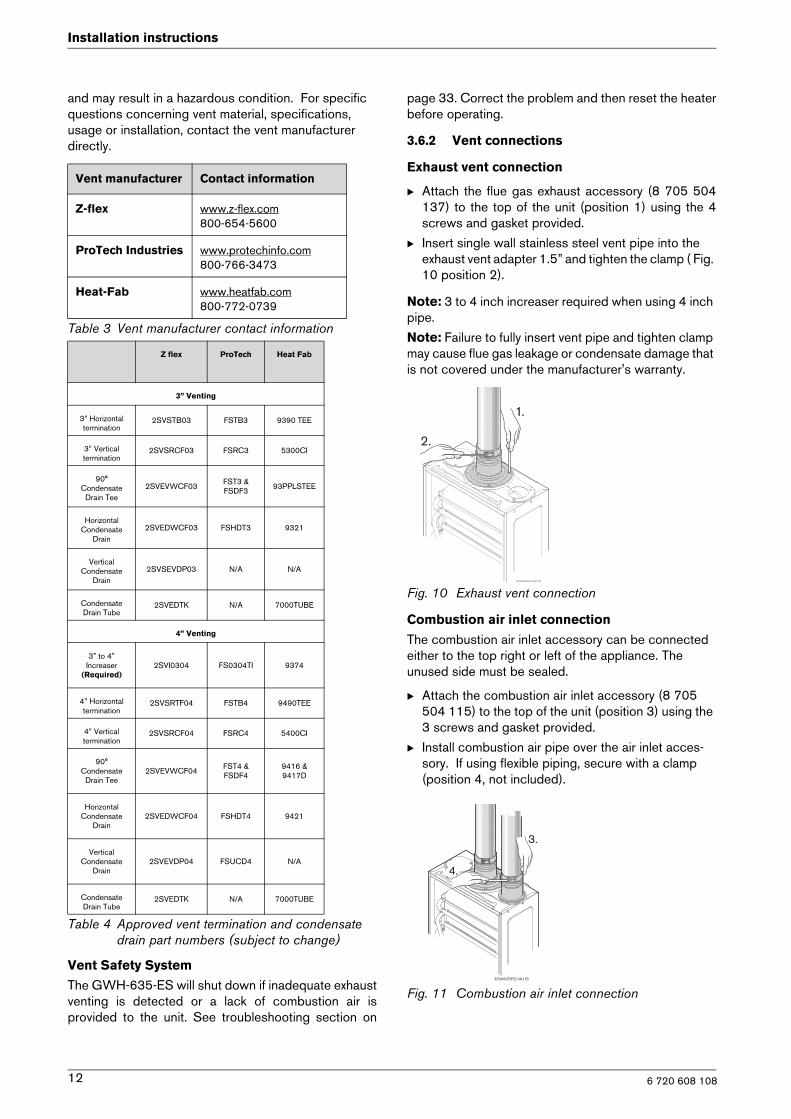
Exhaust vent connection
B Attach the flue gas exhaust accessory (8 705 504137) to the top of the unit (position 1) using the 4screws and gasket provided.
B Insert single wall stainless steel vent pipe into the exhaust vent adapter 1.5” and tighten the clamp ( Fig. 10 position 2).
Note: 3 to 4 inch increaser required when using 4 inch pipe.
Note: Failure to fully insert vent pipe and tighten clamp may cause flue gas leakage or condensate damage that is not covered under the manufacturer's warranty.
Fig. 10 Exhaust vent connection
Combustion air inlet connection
The combustion air inlet accessory can be connected either to the top right or left of the appliance. The unused side must be sealed.
B Attach the combustion air inlet accessory (8 705 504 115) to the top of the unit (position 3) using the 3 screws and gasket provided.
B Install combustion air pipe over the air inlet acces-sory. If using flexible piping, secure with a clamp (position 4, not included).
Fig. 11 Combustion air inlet connection
Vent manufacturer Contact information
Z-flex www.z-flex.com800-654-5600
ProTech Industries www.protechinfo.com800-766-3473
Heat-Fab www.heatfab.com800-772-0739
Table 3 Vent manufacturer contact information
Z flex ProTech Heat Fab
3” Venting
3” Horizontal termination
2SVSTB03 FSTB3 9390 TEE
3” Vertical termination
2SVSRCF03 FSRC3 5300CI
90° Condensate
Drain Tee2SVEVWCF03 FST3 &
FSDF3 93PPLSTEE
Horizontal Condensate
Drain2SVEDWCF03 FSHDT3 9321
Vertical Condensate
Drain2SVSEVDP03 N/A N/A
Condensate Drain Tube
2SVEDTK N/A 7000TUBE
4” Venting
3” to 4” Increaser
(Required)2SVI0304 FS0304TI 9374
4” Horizontal termination
2SVSRTF04 FSTB4 9490TEE
4” Vertical termination
2SVSRCF04 FSRC4 5400CI
90° Condensate
Drain Tee2SVEVWCF04 FST4 &
FSDF49416 & 9417D
Horizontal Condensate
Drain2SVEDWCF04 FSHDT4 9421
Vertical Condensate
Drain2SVEVDP04 FSUCD4 N/A
Condensate Drain Tube
2SVEDTK N/A 7000TUBE
Table 4 Approved vent termination and condensate drain part numbers (subject to change)

6 720 608 108
Installation instructions
13
3.6.3 Condensate drain tube requirements
Exhaust collar condensate drain installation (supplied with heater)
B The condensate drain tube kit must be used for all installation types. Failure to properly install con-densate drain will void the warranty.
B When installing the condensate drain tube kit on the exhaust collar (see diagram below), be sure to form a trap by means of a 3" (76.2 mm) loop partially filled with water. This loop must be as low as possible to allow proper drainage of condensate. The supplied tube is 3/8" ID high temperature silicone and must be attached to the condensate port on the exhaust collar with its supplied gear clamp (first remove brass screw from port).
B To increase tube length, connect vinyl tubing (not supplied with heater) to the supplied tube. Do not reduce tubing diameter when using connector or additional tubing.
B The condensate must be disposed of according to local regulations.
Fig. 12 Exhaust collar condensate drain installation
Note: No part of supplied silicone tube should be installed above condensate tapping or improper drain-age may occur. (see Fig. 12).
External condensate drain installation (not sup-plied)
An additional external condensate drain must be installed under the following conditions:
• Vertical terminating vent installations
• Horizontal terminating vent installations where the total vent length is greater than 5 feet
• Vent installation where any section of the exhaust vent pipe passes through an unconditioned space.
Note: Condensate must be disposed of according to local codes.Note: Do not install condensate drain in areas where it may freeze.
1. Install condensate drain as close to heater as possible.
2. Use 3/8" ID high temperature silicone tubing to connect to condensate drain port. Do not use copper piping for any portion of the condensate drain.
3. Form a condensate trap by means of a 3" loop and fill bottom of loop with water.
4. To increase the tube length, connect to end of the high temperature silicone tubing with vinyl tubing, PVC or CPVC pipe. Do not reduce the internal diameter at any point.
5. Dispose of condensate according to local codes.
Fig. 13 Required condensate drain installation(Combustion air piping not shown)
3.6.4 Room sealed installation (Twin pipe)
B Although it is permitted to draw combustion air from inside the structure in warm climates, the recom-mended method is to provide combustion air through
Condensate port on exhaust collar
2. Fit tube with gear clamp
3. Loop size and location. Coil tube into 3” loop with nylon tie (don't crimp tubing) and fill bottom of loop with water
1. Remove brass hex head screw
Warning: In areas where outdoor temperatures commonly fall below 36°F, a twin pipe venting system is required. Failure to do so may result in cold outside air being drawn across the heat exchanger causing it to freeze and burst. This failure is not covered under the manufacturer's warranty.

6 720 608 10814
Installation instructions
a 3" or 4" pipe from the outside. See Chapter 3.5 for more direction on combustion air.
B To reduce pressure differentials between the exhaust and combustion air intake, it is recommended that both terminators exit on the same plane. See Fig. 14 for an example horizontal twin pipe termination and Fig. 15 for the vertical twin pipe termination example.
Fig. 14 Horizontal twin pipe termination
Fig. 15 Vertical twin pipe termination
3.6.5 Vertical terminations
Horizontal runs
Any gas vent section that is greater than 45 degrees from the vertical is considered horizontal. Horizontal sections must slope upwards from heater at least ¼ inch for every foot of its horizontal length and be prop-erly supported to allow condensate to be collected by condensate drains.
Vent terminations
B No pipe joints other than the termination connections should be exposed to the outdoors. See vent manu-facturer instructions for details.
B Use of two 90° elbows (candy-cane) is an accepta-ble termination for combustion air intake from the roof. See Fig. 15 for an example.
B Screening (no smaller than 1/4" mesh) is recom-mended on candy cane termination.
B Exhaust should terminate above and must be a mini-mum of 3 feet from must intake termination.
B The exhaust vent must terminate above the roof sur-face with an approved vent cap not less than 3 feet (0.6 m) above the highest point where it passes through the roof and at least 2 feet (0.6 m) higher than any vertical wall or similar obstruction within 10 feet (3.1m). See Fig. 16 and Table 5.
Fig. 16 Vertical vent terminations clearances(Combustion air piping not shown)
Warning: Failure to install a condensate drain may result in damage not covered by the manufacturer's warranty. See chapter 3.6.3.An approved vent terminator must be used. See Table 5 for known approved vertical vent terminations.
GAS VENT TERMINATIONS FOR LISTED VENT CAPS
Roof pitch H (min.) feet
meters
Flat to 6/12 1.0 0.30
6/12 to 7/12 1.25 0.38
Over 7/12 to 8/12 1.5 0.46
Over 8/12 to 9/12 2.0 0.61
Over 9/12 to 10/12 2.5 0.76
Over 10/12 to 11/12 3.25 0.99
Over 11/12 to 12/12 4.0 1.22
Over 12/12 to 14/12 5.0 1.52
Over 14/12 to 16/12 6.0 1.83
Over 16/12 to 18/12 7.0 2.13
Over 18/12 to 20/12 7.5 2.27
Table 5 Termination heights at various roof pitches

6 720 608 108
Installation instructions
15
Interior masonry chimneys
The single wall stainless steel exhaust vent pipe must be permanently mounted inside the masonry chimney. The masonry chimney may have to be tile or metal lined before the insertion of the gas vent pipe; check local codes for clarification. You may not vent any other fuel burning appliances into any free space remaining in the chimney. The vent terminator must extend at least 3 feet (0.9 m) above where the chimney meets the roofline and at least 2 feet (0.6 m) higher than any vertical wall or similar obstruction within 10 feet (3.1 m). The top of the chimney must be sealed to prevent rain water or other elements from entering the chimney.
Exterior masonry chimneys
Refer to the National Fuel Gas Code and consult a local venting HVAC contractor. Not recommended in cold climates.
3.6.6 Horizontal terminations
• For horizontal vent runs less than 5 linear feet, the entire vent run must pitch down to termination 1/4" per foot to eliminate the danger of rain from entering the venting system.
• The exhaust vent must terminate immediately once it penetrates the outside wall.
• An approved vent terminator must be used. See Table 4 for known approved horizontal vent terminations.
• Install an additional condensate drain (not supplied) if the total straight vent length is greater than 5 feet or if the exhaust vent pipe passes through an unconditioned space.
• Terminating the intake air piping above the exhaust termination is not recommended.
• Fig. 17 and table 6 show the required clearances for the vent termination. Follow local codes if more stringent.
3.6.6.1 Attention residents of the Commonwealth of Massachusetts:
In the Commonwealth of Massachusetts the following regulation went into effect on 12/30/2005:
(a)For all side wall horizontally vented gas fueled equip-ment installed in every dwelling, building or structure used in whole or in part for residential purposes, includ-ing those owned or operated by the Commonwealth and where the side wall exhaust vent termination is less than seven (7) feet above finished grade in the area of the venting, including but not limited to decks and porches, the following requirements shall be satisfied:
1. INSTALLATION OF CARBON MONOXIDE DETEC-TORS. At the time of installation of the side wall hor-
izontal vented gas fueled equipment, the installing plumber or gasfitter shall observe that a hard wired carbon monoxide detector with an alarm and battery back-up is installed on the floor level where the gas equipment is to be installed. In addition, the installing plumber or gasfitter shall observe that a battery oper-ated or hard wired carbon monoxide detector with an alarm is installed on each additional level of the dwell-ing, building or structure served by the side wall hor-izontal vented gas fueled equipment. It shall be the responsibility of the property owner to secure the services of qualified licensed professionals for the installation of hard wired carbon monoxide detectors.a. In the event that the side wall horizontally vented gas fueled equipment is installed in a crawl space or an at tic, the hard wired carbon monoxide detector with alarm and battery back-up may be installed on the next adjacent floor level.b. In the event that the requirements of this subdivi-sion can not be met at the time of completion of installation, the owner shall have a period of thirty (30) days to comply with the above requirements; provided, however, that during said thirty (30) day period, a battery operated carbon monoxide detector with an alarm shall be installed.
2. APPROVED CARBON MONOXIDE DETECTORS. Each carbon monoxide detector as required in accordance with the above provisions shall comply with NFPA 720 and be ANSI/UL 2034 listed and IAS certified.
3. SIGNAGE. A metal or plastic identification plate shall be permanently mounted to the exterior of the build-ing at a minimum height of eight (8) feet above grade directly in line with the exhaust vent terminal for the horizontally vented gas fueled heating appliance or equipment. The sign shall read, in print size no less than one half (1/2) inch in size, "GAS VENT DIRECTLY BELOW. KEEP CLEAR OF ALL OBSTRUCTIONS".
4. INSPECTION. The state or local gas inspector of the side wall horizontally vented gas fueled equipment shall not approve the installation unless, upon inspection, the inspector observes carbon monoxide detectors and signage installed in accordance with the provisions of 248 CMR 5.08(2)(a)1 through 4.(b) EXEMPTIONS: The following equipment is exempt from 248 CMR 5.08(2)(a)1 through 4:1.The equipment listed in Chapter 10 entitled "Equipment Not Required To Be Vented" in the most current edition of NFPA 54 as adopted by the Board; and2. Product approved side wall horizontally vented gas fueled equipment installed in a room or structure separate from the dwelling, building or structure used in whole or in part for residential purposes.(c) MANUFACTURERS REQUIREMENTS - GAS
Over 20/12 to 21/12 8.0 2.44
Table 5 Termination heights at various roof pitches

6 720 608 10816
Installation instructions
EQUIPMENT VENTING SYSTEM REQUIRED. When the manufacturer of Product Approved side wall horizontally mounted gas equipment provides a venting system design or venting system compo-nents with the equipment, the instructions provided by the manufacturer for the installation of the equip-ment and the venting shall include:1. Detailed instructions for the installation of the vent-ing system or the venting system components: and2. A complete parts list for the venting system design or venting system.(d) MANUFACTURER REQUIREMENTS - GAS EQUIPMENT VENTING SYSTEM NOT PROVIDED. When the manufacturer of a product approved side wall horizontally vented gas fueled equipment does not provide the parts for the venting of flue gases, but identifies "special venting systems," the following requirements shall be satisfied by the manufacturer:1. The referenced "special venting system" instruc-tions shall be included with the appliance or equip-ment installation instructions; and2. The "special venting systems" shall be product approved by the Board, and the instructions for that system shall include a parts list and detailed installa-tion instructions.(e) A copy of all installation instructions for all prod-ucts approved side wall horizontally vented gas fueled equipment, all venting instructions, all parts lists for venting instructions, and/or all venting design instructions shall remain with the appliance or equip-ment at the completion of the installation.

6 720 608 108
Installation instructions
17
Recommended exhaust vent terminator clearances
Fig. 17
* Subject to local codes and anticipated snow level
** Other equipment that operates with a mechanical air inlet may require greater distances, reference manufacturer's instructions
NOTE: terminating exhaust vent under a deck is not recommended
Ref. Description Minimum distance
ADirectly below an opening; operable windows, doors and any non-mechanical fresh air openings
36 in (twin pipe installation)48 in (single pipe installation)
B
Below a gutter, sanitary pipework or eaves 24 in
Below a gutter, sanitary pipework or eaves, protected by metal shielding
12 in
C From any internal corner 12 in
D*Above ground or snow pack 12 in
Above a paved sidewalk 7 ft
EFrom an opposing wall or structure facing the termination 24 in
From the relief valve of a gas regulator 36 in
F From a terminator facing a terminator 48 in
G Vertically between two exhaust vent terminators on the same wall 60 in
H Horizontally between two exhaust vent terminators on the same wall 12 in
I**
Horizontally and vertically from combustion air inlet of a twin pipe system 36 in
From the gravity combustion air inlet any other equipment 48 in
J From any external corner 12 in
KHorizontally from an opening; operable windows, doors and any non-mechanical fresh air openings
12 in (twin pipe installation)48 in (single pipe installation)
LVertically from a wall, roof slope, or obstruction (venting through a flat or pitched roof)
see Chapter 3.6.5
Table 6

6 720 608 10818
Installation instructions
3.6.7 Exhaust vent configuration examples
Supporting the exhaust vent system
Fig. 18 Horizontal side wall venting installation(combustion air piping not shown)
Note: Pitch venting up 1/4" per foot to termination and add additional condensate drain for vent runs longer than 5 linear feet.Note: Pitch venting down 1/4" per foot to termination for vent runs less than 5 linear feet.Note: For horizontal terminations, venting must terminate once it penetrates to the outside of the structure. There should be no sections of vent pipe exposed to the outdoors.
Fig. 19 Vertical venting installation (combustion airpiping not shown)
Fig. 20 Vertical venting installation - Interior masonryChimney (combustion air piping not shown)

6 720 608 108
Installation instructions
19
3.7 Gas piping & connections
Before connecting the gas supply, check the ratingplate on the right side of the heater to be sure that theheater is rated for the same gas to which it will beconnected.In the United States: The installation must conform withlocal codes or, in the absence of local codes, theNational Fuel Gas Code ANSI Z223.1/NFPA 54.In Canada: The Installation must conform to CGA B149INSTALLATION CODES and/or local installationcodes.
GAS CONNECTIONS
B Install a manual gas shut off valve on the gas supplyline.
B Install a union when connecting gas supply.
B The minimum diameter required for any applianceconnector used is ¾” ID.
B National Fuel Gas Code requires that a sedimenttrap (drip leg) be installed on gas appliances not soequipped. The drip leg must be accessible and notsubject to freezing conditions. Install in accordancewith the recommendations of the serving gassupplier.
Once connections are made, check for gas leaks at all joints. Apply some gas leak detection solution to all gas fittings. Bubbles are a sign of a leak. A combustible gas detector may also be used to detect for leaks.
GAS LINE SIZINGThe gas supply piping should be sized for a maximumdraw of 175,000 BTUH. Measure the length of gassupply line and use the tables in Fig. 22 or the gas line
manufacturer’s sizing tables to determine the pipediameter necessary to accommodate the 175,000 BTUdemand of the heater. If there are more gas drawingappliances on the line, size the gas line according to thetotal maximum amount of BTU draw for all appliances.
Note: Under sizing the gas line may result in diminishedoutput and improper operation. See chapter 3.8 for theprocedure to confirm gas pressure. Proper gaspressure must be confirmed at time of installation.
Fig. 21
Warning: DO NOT connect to an unregulated or high pressure propane line or to a high pressure commercial natural gas line.
Warning: The heater must be isolatedfrom the gas supply piping systemduring any pressure testing of thatsystem at test pressures equal to ormore than 0.5 psig. If overpressure hasoccurred, such as through impropertesting of the gas lines or malfunction ofthe supply system, the gas valve mustbe checked for safe operation.
Danger: If you have a leak, shut off thegas. Tighten appropriate fittings to stopleak. Turn the gas on and check againwith a gas leak detection solution.Never test for gas leaks using a matchor flame.
Gas piping
Inlet gas particle screen

6 720 608 10820
Installation instructions
FOR NATURAL GASMaximum Capacity of pipe in Cubic Feet of Gas per Hour for Gas Pressure of 0.5 Psig or less and a Pressure dropof 0.3” in Water Column (0.75mbar).(Based on a 0.60 Specific Gravity Gas) Btu numbers given in thousands.
Fig. 22
Follow boxed numbers for piping just one GWH-635-ES (example: ¾” B.I. Natural Gas pipe for 20 ft (6.1m).will handle 190,000 btu’s (55.7 kWh). For multiple appliances combine the total btu input load and then referto applicable chart below.
Nominal
Iron Length of Black Iron Pipe, Feet
Pipe Internal
Size, Diameter
inches inches 10 20 30 40 50 60 70 80 90 100 125 150 175 200
1/4 0.364 32 22 18 15 14 12 11 11 10 9 8 8 7 6
3/8 0.493 72 49 40 34 30 27 25 23 22 21 18 17 15 14
1/2 0.622 132 92 73 63 56 50 46 43 40 38 34 31 28 26
3/4 0.824 278 190 152 130 115 105 96 90 84 79 72 64 59 55
1 1.049 520 350 285 245 215 195 180 170 160 150 130 120 110 100
1 1/4 1.380 1050 730 590 500 440 400 370 350 320 305 275 250 225 210
1 1/2 1.610 1600 1100 890 760 670 610 560 530 490 460 410 380 350 320
2 2.067 3050 2100 1650 1450 1270 1150 1050 990 930 870 780 710 650 610
* EHD = Equivalent Hydraulic Diameter. The greater thevalue of EHD, the greater the gas capacity of the tubing.
Maximum Capacity of Semi-Rigid (flexible, non
corrugated) Tubing in Thousands of BTU per Hour of
Undiluted Liquefied Petroleum Gases (at 11 inches
Water Column Inlet Pressure).
(Based on a Pressure Drop of 0.5 Inch Water Column)
* Source National Fuel Gas Code NFPA 54, ANSIZ223.1 - No Additional Allowance is necessary for anordinary number of fittings
FOR LP GASMaximum Capacity of Pipe in Thousands of BTU per Hour of Undiluted Petroleum Gases (at 11 inches Water Column InletPressure) (Based on a Pressure Drop of 0.5 Inch Water Column).
CopperOutside Length of Tubing, FeetdiameterInch 10 20 30 40 50 60 70 80 90 100
3/8 39 26 21 19 _ _ _ _ _ _
1/2 92 62 50 41 37 35 31 29 27 26
5/8 199 131 107 90 79 72 67 62 59 55
3/4 329 216 181 145 131 121 112 104 95 90
* EHD = Equivalent Hydraulic Diameter. The greater thevalue of EHD, the greater the gas capacity of the tubing.
Tubesize,inches EHD*
10 20 30 40 50 60
1/2 18 EHD 82 58 47 41 37 34
3/4 23 EHD 161 116 96 83 75 68
1 30 EHD 330 231 188 162 144 131
1 1/4 37 EHD 639 456 374 325 292 267
Length of Flexible Corrugated Stainless Steel Tubing (CSST), Feet
Tubesizeinches EHD*
10 20 30 40 50 60
1/2 18 EHD 129 91 74 64 58 53
3/4 23 EHD 254 183 151 131 118 107
1 30 EHD 521 365 297 256 227 207
1 1/4 37 EHD 971 661 528 449 397 359
Length of Flexible Corrugated Stainless Steel Tubing (CSST), Feet Nominal
iron Black Iron Pipe
pipe Length of Pipe, Feet
Inches 10 20 30 40 50 60 80 100 125 150 200
1/2 291 200 160 137 122 110 94 84 74 67 58
3/4 608 418 336 287 255 231 197 175 155 140 120
1 1145 787 632 541 480 434 372 330 292 265 227

6 720 608 108
Installation instructions
21
3.8 Measuring gas pressure
Confirm proper gas pressure upon installation.
Connecting Manometer
B Shut off gas supply at installer supplied shutoff valve.
B Remove front cover and locate inlet gas pressuremeasuring point (see Fig. 24).
B Loosen screw inside left test point fitting (do notremove) and connect manometer tube to test point.Remove screw completely if correct size adapter isavailable.
Static Pressure Test
B Turn gas supply back on.
B Operate all other gas appliances (except heater) onsame gas piping system at maximum output.
B Record static gas pressure reading in table 7.
Operating Pressure Test
B ON/OFF switch in position OFF (0).
B Press and hold "Program" (P) button and turn ON/OFF switch to ON position.
Fig. 23
B As soon as '188' is displayed, release "Program", button and the display should read P2.
B Press until P1 appears.
Note: While in this mode the appliance will runconstantly at maximum power and allow maximum waterflow.
B Turn on a high volume of hot water (at least 4 gpm)and heater will ignite. If heater display reverts to P2,open more hot water fixtures to allow sufficient flow.Press until P1 reappears on display.
B Record lowest operating gas pressure reading intable 7.
Gas pressures lower than 5" W.C. for Natural Gas or11" W.C. for LPG will result in insufficient degree riseto the hot water being used, possible error code faultsand must be corrected. See Gas Connections,chapter 3.7.
Fig. 24 Gas pressure measuring (left tapping)
HIGH ALTITUDE OPERATION
Static Gas Pressure Reading (see Chapter 3.8)
enter here: ___________________ Date: ___________
Operating Gas Pressure Reading (see Chapter 3.8)
enter here: ___________________ Date: ___________
Table 7
Altitude Natural Gas:
Liquid Propane:
0 - 4,000 ft(0 - 1,219 m)
no modification
no modification
For operation at elevations
above 2,000 ft (610 m) the equipment
ratings shall be reduced at the rate of 4% for each 1,000 ft (305 m) above
sea level
4,000 ft - 7,000 ft(1,219 m - 2,134 m)
CO2 adjustment with flue gas analyzer required See
section 5.4 for instructions.
Above 7,000 ft(above 2,134 m) Not approved
Table 8

6 720 608 10822
Installation instructions
3.9 Water connections
B When facing the heater, the ¾” cold inlet connection is on the bottom right and the hot connection is on the bottom left. Centrally locating the water heater is recommended to keep hot water distribution times even throughout the structure.
Fig. 25
B The use of unions when connecting both water pipesto the cold and hot water connections is required.This will facilitate any necessary servicing.
B Plastic or PEX type plumbing line materials are notsuitable for connecting directly to the water heater.
B Although water piping throughout the building may be other than copper, we recommend that copper or suitably rated stainless steel flex line piping be used for the water connections for 1.5’ on either side of the water heater (follow local codes if more strin-gent).
B Never sweat any rigid piping directly to or beneaththe water connections, as damage can occur to theinternal water valve from heating of the pipe.
B Keep water inlet and outlet pipes to no less than ¾"(19.05mm) diameter to allow the full flow capacity.
B If the cold and hot connections to the heater arereversed, the heater will not function. Be certain thereare no loose particles or dirt in the piping. Blow out
or flush the lines before connecting to the waterheater.
B Full port shutoff valves should be installed on boththe cold water supply and hot water outlet lines tofacilitate servicing the heater (see Fig. 26).
Note: If water flow or pressure is low, or heater does not ignite, check the water inlet filter screen for debris (see Chapter 5.1).
Connecting the pressure relief valve (PRV)A listed pressure relief valve supplied with the heatermust be installed at the time of installation. No valve isto be placed between the PRV and the heater. Noreducing coupling or other restriction may be installedin the discharge line. The discharge line must be aminimum of 4” above a drain and installed such that itallows complete drainage of both the PRV and the line.The location of the PRV must be readily accessible forservicing or replacement, and be mounted as close tothe water heater as possible. See Fig. 26. To install thePRV, a suitable fitting connected to an extension on a“T” fitting can be sweated to the hot water line.Support all piping.
Fig. 26 Plumbing connections (with isolation valves)and pressure relief valve
Warning: This heater must be suppliedwith cold potable water. It is notapproved for preheated waterapplications. See chapter 3.12 forapproved recirculating application.
Warning: In areas where the water supply has a high mineral content, a water softener is strongly recommended. Damage to the water heater resulting from hard water/scale deposits will not be covered under warranty.
HOT
INLETFILTER
COLD
UNION (not sup-plied with heater)

6 720 608 108
Installation instructions
23
3.10 Electrical connections
The GWH-635-ES requires an electrical power supplyfrom a 120VAC / 60Hz circuit (with a dedicated outlet)and must be properly grounded.A means for switching off the 120VAC power supplymust be provided.The heater is wired as shown in the wiring diagram(chapter 7, Fig. 44).
3.11 Cascading function
Cascading enables the appliance to be connected inparallel with up to 4 appliances. An appliance in thissystem will only start, if it gets a signal from theappliance before it. That means, the appliance worksalways as a Master to the next appliance and always asa Slave to the one before.
For more detailed information about this feature, consult the instructions supplied with the accessory:
• 7 709 003 617.
3.12 Recirculation application
Since recirculation through the heater is notpermissible, the following drawing is provided to outlinea proper recirculation application using the Aquastarwater heater with an Ariston minitank water heater. Thisschematic is for illustration only and must not be usedfor actual installation without appropriate engineeringand technical advice from a properly licensedprofessional in the locality where the installation ismade.
Fig. 27 Recirculation application1 Full port isolation valve2 Circulator3 Check valve4 PRV5 Expansion tank
The use of a small electric mini-tank water heater (4-6gallon size) should be used for this application anddesigned so the pump will circulate the water throughthe mini-tank and the building's hot water return looponly. Timed or thermostatically controlled operation ofthe pump is commonly done. The GWH-635-ES mustbe supplied with cold water only and plumbed in linebefore the mini-tank water heater. Contact BoschWater Heating if further information is needed.
Warning: For safety reasons,disconnect the power supply cord tothe heater before any service or testingis performed.
Warning: This heater must beelectrically grounded in accordancewith the most recent edition of theNational Electrical Code NFPA 70. InCanada, all electrical wiring to theheater should be in accordance withlocal codes and the Canadian ElectricalCode, CSA C22.1 Part 1. Do not relyon the gas or water piping to ground themetal parts of the heater.
Ariston Minitank
GWH635 ES

6 720 608 10824
Operation instructions
4 Operation instructions
Fig. 281 On/Off switch2 Reset button3 Program “ “ button4 Increasing temperature selector5 Decreasing temperature selector6 LCD display
4.1 For your safety, read before oper-ating your water heater
A. This appliance is equipped with electronic ignition for lighting the main burners. When turning the heater on, follow these instructions exactly.B. Before operating the unit, set the On/Off switch to the On ( I ) position.
WHAT TO DO IF YOU SMELL GAS
B Do not try to light any appliance.
B Do not touch any electric switch; do not use anyphone in your building.
B Immediately call your gas supplier from a neighborsphone. Follow the gas supplier’s instructions.
B If you cannot reach your gas supplier, call the firedepartment.
C. Use only your hand to turn the on/off control switch.Never use tools. Follow these instructions exactly. Ifcontrol switch is jammed, close the gas supply and callBosch Technical Support. Attempted forceful repairmay result in a fire or explosion.D. Do not use this appliance if any part has been underwater. Immediately call a qualified service technician toinspect the appliance and to replace any part of thecontrol system and any gas control which has beenunder water.
4.2 Power
On
B To start the appliance move the on/off switch to the"on" position (I).LCD will display the default temperature factorysetting 122°F (50°C).
Fig. 29
Warning: The front cover of thisappliance must be secured andproperly sealed at all times once ventpipe and water connections are made.Failure to do so may result in freezing(not covered under warranty), improperfuel air mixture or error code faults.
Warning: If you do not follow theseinstructions exactly, a fire or explosionmay result causing property damage,personal injury or loss of life.

6 720 608 108
Operation instructions
25
Off
B To shut down the appliance move the on/off switch to the “off” position (0).
4.3 Temperature selection
To select output water temperature:
B Press buttons and in order to reach desiredtemperature.
Fig. 30
If the outlet water temperature is set too high, the heatercan produce temperatures that are too hot. Atemperature balance shower valve will automatically mixin cold water to reduce such hot water temperature. Inthe event of any temperature fluctuation with the use ofa temperature balance shower valve, refer to showervalve manufacturer's instructions for internal adjustmentsetting. Adjustments should be made to the hottestsetting in the shower valve. Additionally the temperaturecontrol of the heater can be lowered to produce a morecomfortable hot water temperature.

6 720 608 10826
Operation instructions
Setting the water temperature
The desired temperature of the hot water can be adjusted on the front control panel of the heater.The GWH-635-ES has an electronically controlled gas valve that modulates the burner input in response to bothvarying hot water flow rates and/or changes in any incoming and outgoing water temperatures.Note: selected temperature on heater’s display will blink until that temperature has been reached.
Fig. 31 Flow/temperature chart
Note: Low flowing fixtures are the leading cause oftemperature overshoot. To combat this symptom, cleanaerators and shower heads or replace with higherflowing fixtures if necessary.

6 720 608 108
Operation instructions
27
4.4 Use of optional remote control accessory
Fig. 32 Remote control
The wireless remote control accessory and thetemperature selector buttons on the front of the waterheater operate identically. Contact your installer ordistributor to order the remote control accessory.Modification of the water heaters interior control unit(Fig. 48, component 25) is required when installing theremote control with this heater.
4.5 Operation
B When a hot water tap is opened, main burner ignitesand LCD displays indication .
Fig. 33
B LCD blinks until selected temperature is reached.
If display blinks continously, heater cannot maintainor achieve selected temperature.
4.6 Reset button
If the LCD displays the error symbol and error codedo not shut off power or unplug the heater.Record the error code displayed on LCD and consult“Troubleshooting” section (Section 6.8, page 36).
Fig. 34
After following instructions indicated in“Troubleshooting” section:
B press reset button in order to return heater to normaloperation.
Fig. 35 Reset button
If the problem persists or error code will not reset,contact your installer.
4.7 Program button
The program button can be used on the appliance andon the remote control.
Programming “Program” functionProgramming actions are similar for both controls(appliance control pad and wireless remote control).
Fig. 36 “Program” button
B Press buttons or to select temperature to be memorized.
B Hold “Program” button for 3 seconds to save temperature.
When LCD stops blinking, selected temperature has been memorized.
Using “Program” functionIn order to select memorized temperature
B Press “Program” key.
LCD shows pre-memorized temperature, which is nowthe hot water selected temperature.
4.8 Locked condition
This condition is only valid for appliances utilizing one ormore remote controls.
Fig. 37 Locked condition
Whenever LCD shows the temperature settingcannot be adjusted because the appliance is in use bya user which already selected a different temperature.Appliance will be automatically unlocked after closinghot water tap.
iNOTE: up to 6 remote controls can beprogrammed for one single water heater,each with a range distance of 98 ft (30 m).

6 720 608 10828
Maintenance and service
5 Maintenance and service
The unit should be checked once a year by a gastechnician. If repairs are needed, the repairs should bedone by a gas technician
5.1 Annual maintenance
(To remove front cover, see page 5.)
Venting System
• Venting system - inspect inside of flue pipe for anyblockage or restriction. Observe burner flamesduring heater operation. Verify that the damper insideflue gas exhaust accessory is able to move freely.(Vent pipe must be removed in order to accessdamper). Inspect the combustion air inlet pipe forblockage or debris. Inspect combustion air andexhaust terminations for blockage or debris.
Combustion chamber
• Inspect burner observation window (Fig. 46, #10) forcracks or leakage of flue gases. Observe burnerflames during heater operation. Flames should besteady and blue with no signs of yellowing. Yellowburner flames are an indication of impropercombustion. Refer to Section 3.5 & 3.6 of thismanual to verify exhaust system and combustion airsupply meets manufacturer's specifications.
Pressure relief valve
• Manually open the pressure relief valve to ensureproper operation.
Inlet water filter
• Verify the inlet filter screen is clean and undamaged.The inlet water filter is located within the ¾" coldwater inlet on the bottom right side of the appliance(See Fig. 25). Close installer supplied cold watershutoff and remove cold water supply pipe. Removefilter, clean or replace if damaged.
Fig. 38
Descaling
• In areas where the water supply has a high mineralcontent, the heat exchanger may need to be flushedwith a descaling solution. Scale build up will shortenthe life of the water heater and damage resulting fromscale is not covered under warranty. Refer tosection 5.3 for detailed instructions on descaling theheat exchanger.
Heat exchanger
• Inspect heat exchanger fincoil for soot build-up orblockage. To access fincoil, venting must beremoved from flue gas exhaust accessory. Withventing removed, manually hold open damper andinspect fincoil below with a flashlight. If there isevidence of soot build-up or blockage, the heatexchanger should be removed by a professsional andcleaned thoroughly. To remove the heat exchanger,consult service bulletin TWH-G2-22 atwww.boschpro.com.
5.2 Winterizing for seasonal use
Please note that installation instructions state that thewater heater must not be installed in a location where itmay be exposed to freezing temperatures. If the heatermust be left in a space which is likely to experiencefreezing temperatures (less than 36° F), all water mustbe drained from the heater. If precautions are not taken,resulting damage will not be covered under thewarranty. NOTE: Use of agents such as anti-freeze isnot recommended as they may cause damage to thewater heater's internal components.
1. Turn on/off switch on the water heater to the off (O) position and unplug power supply cord. The display should be blank.
2. Shut off gas supply to heater.
3. Shut off the water supply to the water heater using installer supplied shutoff valve.
4. Open hot water taps to drain and relieve pressure from the plumbing system. If water continues to flow after 5 minutes, a plumbing crossover is present and must be corrected before proceeding.
5. Disconnect inlet and outlet water pipes from the water heater. Place a small bucket underneath the water heater to catch residual water remaining inside the water heater. Save washers for future use.
6. Using an air compressor, blow short bursts of air (100 PSI Maximum) through the inlet water connec-tion until there is no water coming out of the outlet water connection of the heater.
7. Reconnect water fittings and return heater to service when danger of freezing has passed.
Warning: Always turn off the electricalpower supply, turn off the manual gasvalve and turn off the manual watercontrol valves when servicing heater.
HOT
INLETFILTER
COLD

6 720 608 108
Maintenance and service
29
5.3 Mineral scale build-up
Periodic descaling may be necessary in areas with highmineral content in the water. Scale buildup in the heatexchanger may result in lower flow rates, error codes ofA7 and E9 and boiling sounds in the heat exchanger.
Descaling using a pump
1. Disconnect electrical supply from the water heater.
2. Shut off the water supply to the water heater using(installer supplied) shut-off valve.
3. Open hot water taps to drain and relieve pressurefrom the plumbing system.
4. Drain water from the unit's heat exchanger bydisconnecting inlet and outlet water connectionsfrom the heater.
5. Connect a line (A) from the outlet of the circulatingpump (installer supplied) to the inlet water fitting onthe water heater.
6. Connect another line (B) to the water outlet fitting onthe water heater. Route the other end of this line intoa descaling reservoir.
7. Using a 3rd line (C) from the descaling reservoir,connect to the inlet side of circulating pump. Install afilter on the end of the line in the descaling reservoir.
8. Make sure all connections are "hand tight.".
9. Fill reservoir with descaling solution so both linesinside are submersed. We recommend straight whitevinegar. If using a commercial descalant, refer tomanufacturer's instructions on dilution with water.
10.Operate the circulating pump.
11.Make sure there are no leaks and the solution isflowing from the descaling reservoir through theheater and returning to the reservoir.
12.Run solution through the heater until the solutionreturning to the descaling reservoir comes out clear.(Changing to a fresh solution may be necessaryduring this process).
13.Disconnect all lines and drain all solution from heatexchanger. Properly discard of solution.
14.Position a container below the hot water outlet andreconnect cold water supply. Open cold watersupply shut-off valve and flush heat exchanger withclean water.
15.Shut cold water shut-off valve and reconnect hotwater line to the water heater.
16.Reconnect electrical supply to unit, open waterisolation valves, and return the unit to service.
Fig. 39
5.4 Adjusting CO2
The CO2 can only be adjusted by a certified gastechnician with a calibrated CO2 analyzer.
Static Gas Pressure: “ WC
P1 Operating Pressure: “ WC
The P1 minimum operating gas pressure is 5" WC forNatural Gas and 11"WC for Propane. Do not proceedin adjusting CO2 until pressure is at or above theselevels, but not to exceed 14” WC.
A. Once Gas Pressure is adequate
B Turn ON/OFF switch to the OFF (O) position.
B Remove brass flat head screw on the exhaust collaras seen in Fig. 40.
B Insert CO2 analyzer probe into the measuring port.The tip of the probe should be in the center of the flue
pipe (approx 1.5" inserted). Avoid air gaps betweenprobe and measuring port as it can alter readings.
Caution: One factor that may affectCO2 levels is improper gas pressure.Please see Chapter 3.8 for theprocedure to measure gas pressureand record your findings below:

6 720 608 10830
Maintenance and service
Fig. 40 Measuring port
B While holding the Program (P) button, turn the ON/OFF switch to ON (I) position (see Fig. 41). As soonas ‘188’ flashes on the display, release the Programbutton. The display should now read P2. Press button until “P1” appears on display.
Fig. 41
B. Measuring CO2 (Cover Installed):
B Open all hot water taps to achieve a flow rate of atleast 4 gallons per minute. (1 tub and 2 sinks shouldbe sufficient).
B Record the CO2 reading in P1 below. (Analyzerreading may take several minutes to stabilize).
B Press the ‘+’ button until P2 appears. Unit will rampdown to low fire and the water flow should decrease.
B Record the CO2 reading in P2 below.
P1 CO2 Reading: % CO2
P2 CO2 Reading: % CO2
C. Adjusting CO2 (cover removed):
Note: when making adjustments with the front cover off, CO2 values will be 0.3 - 0.5% lower than with the front cover on. Adjust values accordingly to make target num-bers in Table 10 when cover is secured.Compare your readings to those found in Table 10. If CO2 readings are off, make adjustments as outlined below.
Note: P1 adjustment will change the P2 reading. Con-firm the P1 value BEFORE adjusting the P2 level.
1. If P1 CO2 level is off:
B Loosen yellow painted philips screw (1) and covershould rotate down (2) revealing a recessed brassslotted screw. Fig. 42.
B Turning the slotted screw counter clockwise willraise P1 CO2 levels and clockwise will lower P1CO2 levels. Adjustments to the slotted screw willalso change P2 CO2 levels.
B After bringing the P1 CO2 readings in range, pressthe button to enter the P2 mode. Verify CO2readings in P2 mode.
Fig. 42 Adjusting P1 CO2 level
2. If P2 CO2 level is off:
B Remove yellow painted #40 Torx cover from the frontof the gas valve. (Fig. 43) A plastic #40 Torx screwwill be revealed.
B Turning the plastic #40 Torx screw counterclockwise will lower P2 CO2 levels and clockwisewill raise P2 CO2 levels.
Note: These screw adjustment are very sensitive andmay take several minutes to stabilize.
CO2 level Max CO level
Nat. Gas
max. input P1 9.7 ± 0.3 %300 ppm
min. input P2 9.5 ± 0.5 %
LP Gas
max. input P1 10.7 ± 0.3 %300 ppm
min. input P2 10.5 ± 0.5 %
* Final reading must be confirmed with the front cover on,CO2 levels increase when the cover is installed.
Table 9

6 720 608 108
Maintenance and service
31
Fig. 43 Adjusting P2 CO2 level
3. Verify both P1 and P2 CO2 readings are within the ranges specified in table 10. Repeat steps 1 and 2 as necesssary until CO2 values are within the specified ranges.
4. Once CO2 values are within the specified ranges, verify the CO readings on P1 do not exceed 300ppm (follow local codes). If values exceed this limit, inspect vent system and fin coils (Chapter 5.1) for blockage.
D. Returning to Service:
1. Return slotted screw cover to original position.2. Reinstall Torx cover.3. Remove CO2 analyzer probe and reinstall flatheadscrew with gasket in exhaust collar.4. Install front cover.5. Turn ON/OFF switch to the OFF (O) position andthen back to the ON (I) position.6. Heater is ready for normal operation.
Final Readings
P2 CO2 Reading: % CO2
P1 CO2 Reading: % CO2
CO2 level Max CO level
Nat. Gas
max. input P1 9.7 ± 0.3 %300 ppm
min. input P2 9.5 ± 0.5 %
LP Gas
max. input P1 10.7 ± 0.3 %300 ppm
min. input P2 10.5 ± 0.5 %
* Final reading must be confirmed with the front cover on,CO2 levels increase when the cover is installed.
Table 10

6 720 608 10832
Maintenance and service
5.5 Control board diagnostics
1. Turn on/off switch on water heater to off (O) position.
2. Press and hold the program ( ) button while turning the on/off switch to the on (I) position. The display will cycle through a startup procedure including the software version.
3. Release the ' ' button when '188' appears on the display. The display should read 'P2' when the program button is released. If not, repeat process.
B Press and release the ' ' button on the controlpanel until the display reads 'P4'. You are now in thediagnostic mode of the control board.
4. When the display reads 'P4', press and release the ' ' button once again and the display should read 'E'.
B Use the ' ' and ' ' button on the control boardto cycle through different diagnostic modesavailable.
5. Once in the selected diagnostic mode of your choice, press and release the ' ' button to display the diagnostic information.
EXAMPLE: to read the flow rate in gallons per minute while the unit is flowing water, cycle to the '3d' mode and press the ' ' button. A reading of 25 on the display would indicate the heater is reading a flow rate of 2.5 gallons/minute.
6. Once the information is obtained, press the ' ' button again to return to the diagnostic mode menu and scroll to addition diagnostic information.
B To exit the diagnostic mode of the heater, use the' ' or ' ' button until the display reads 'E'.
7. Press the ' ' button once again and the display should read P4.
8. Turn the on/off switch off (O) and back on (I) again to return heater to normal function.
Diagnostic menu
E Entry/Exit into sub-modes
0d Set-point temperature
1d Inlet water temperature (F)
2d Outlet water temperature (°F)
3d Water flow (gallons/min)
4d Gas type (LP or NG)
5d Fan speed (Hz)
6d Burner power (%)
7d Maximum power (kW)
8d PWM cycle (signal to fan)
9d Appliance selection
1F Most recent error/failure
2F 2nd most recent error
3F 3rd most recent error
4F 4th most recent error
5F 5th most recent error
6F 6th most recent error
7F 7th most recent error
8F 8th most recent error
9F 9th most recent error
10F 10th most recent error
Table 11

6 720 608 108
Troubleshooting
33
6 Troubleshooting
6.1 Introduction
Many of the questions customers ask regardingoperation of this unit can be answered by following thetroubleshooting steps as outlined below. Visit our website at www.boschpro.com for more detailedtroubleshooting. For best results, perform each stepbefore proceeding to the next. The suggested solutionsmay require that the cover be taken off. (See Page 5.Fig. 3).
6.2 Burners do not ignite when hot water is turned on
1. If the display is blank, verify power to electrical outlet.(120VAC/60Hz properly grounded circuit required).Verify that the heater on/off switch is in the on (I)position.
2. Verify the fuses in the control unit are good.Toaccess fuses, the control unit must be removed. Goto www.boschpro.com for a detailed service bulletinon this process. Two spare fuses are located insidelower access panel of control unit.
3. Make sure cold water inlet connection is plumbed tothe right side of heater when facing unit. See Fig. 25.
4. A minimum of 0.8 gallons per minute (GPM) (3 l/m)is required to activate the heater. A quart containershould fill in 20 seconds or less to activate heater.
5. Clean inlet filter screen per chapter 5.2.
6. Inspect the water path for obstructions. Make sure allshowerheads, faucet aerators and whole housefilters are clear of debris.
7. The heater activates when the water flow through theunit is at or above the required minimum of 0.8 GPM(3 l/m). A crossover creates back pressure on thewater flowing through the heater. Therefore, a higherflow rate than normal is needed to force the heater toactivate. To check for a plumbing crossover, shut offthe cold water supply feed to the water heater. Thenopen all of the hot water taps served by the heater.Wait 10 minutes and check for water flow at taps.There should be no water flowing. Any continuousflow of water indicates a crossover is present andmust be corrected. Consult a professional plumberfor help in correcting a crossover. Failing single leverfaucets and mixing valves are common causes ofplumbing crossovers.
8. With the ON/OFF switch turned to OFF (O) positionand the power supply cord unplugged, remove the
unit's front cover (See Page 5. Fig 3). Check wireconnections between the water valve, control unitand electrode set. See chapter 9.2 for location ofthese parts.
6.3 Water is too hot
1. Selected temperature on the unit is too high. Tolower output temperature, see chapter 4.3.
2. Clean inlet filter screen per chapter 5.1.
3. Inspect the water path for obstructions. Make sure allshowerheads, faucet aerators and whole housefilters are clear of debris.
4. Confirm the heater's gas type coincides with the typeof gas being supplied. See Fig. 2 for location ofrating plate.
5. This model is designed for cold water supply only.For solar preheated applications, use of the model125BS is recommended.
6. If the inlet cold water temperature is greater than70°F due to geographic location avoid restrictiveoutlets. Clean all showerheads and faucet aerators. Itmay be necessary to upgrade to higher flow ratefixtures if allowable by local code.
7. In areas where water has a high mineral content,periodic descaling may necessary. See chapter 5.3for directions.
8. Ensure that both temperature sensors are makingcontact and firmly mounted on their respective coldand hot water pipes. The hot water sensor should belocated on the horizontal section of the hot waterpipe before it exits the heater. The cold water sensoris located on the first horizontal section of pipe as thewater comes into the heater.
6.4 Water is not hot enough
1. Selected temperature on the unit is too low. To raise output temperature, see chapter 4.3.
2. Clean inlet filter screen. See chapter 5.1.
3. Inspect the water path for obstructions. Make sure all showerheads, faucet aerators and whole house filters are clear of debris.
4. Confirm the heater's gas type coincides with the type of gas being supplied. See Fig. 2 for location of rating plate.
5. Check inlet gas particle screen for blockage at gas inlet connection on bottom of unit.
6. Verify gas pressure is in accordance with specifications in chapter 3.8. A gas pressure reading is needed to proceed further. Contact your original installer or a local certified gas technician to obtain this reading.
Warning: If you are unable to performthe tasks listed below, or needadditional assistance please contactyour original installer/licensed gastechnician.

6 720 608 10834
Troubleshooting
7. Cold water is mixing into the hot water lines (plumbing crossover). A plumbing crossover can unintentionally mix cold water with the hot water leaving the heater. The end result is a cooler water temperature than desired. To check for a plumbing crossover, shut off the cold water supply feed to the water heater. Then open all of the hot water taps served by the heater. Wait 10 minutes and check all taps for water flow. There should be no water flowing. Any continuous flow of water, small or large, indicates a crossover and must be corrected. Failing single lever faucets and mixing valves are common causes of plumbing crossovers.
8. Ensure that both temperature sensors are making contact and firmly mounted on their respective cold and hot water pipes. The hot water sensor should be located on the horizontal section of the hot water pipe before it exits the heater. The cold water sensor is located on the first horizontal section of pipe as the water comes into the heater.
6.5 Low water flow/pressure
1. Too many hot water applications are being usedsimultaneously or too much flow is demanded. Thewater heater will effectively support two 2.0-2.5GPM shower heads simultaneously or multiple sinkapplications. Greater draws will result in a waterpressure drop and reduced flow at taps.
2. Ensure that gas pressure is in accordance withspecifications in chapter 3.8. A gas pressure readingis needed to proceed further. Contact your originalinstaller or a local certified gas technician to obtainthis reading. If gas pressure is inadequate, the waterheater will close its motorized water valve, reducingthe hot water flow rate in an attempt to reach theselected output temperature.
3. If selected temperature on the unit is set too high forthe demanded flow rate, the water heater will closeits motorized water valve, reducing the hot water flowrate in an attempt to reach the selected outputtemperature. Lowering the selected temperature willallow the motorized water valve to open up forincreased water flow rate.
4. Clean inlet filter screen per chapter 5.1.
5. Inspect the water path for obstructions. Make sure allshowerheads, faucet aerators and whole housefilters are clear of debris.
6.6 Hot water temperature fluctuatesat tap
Note: Temperature fluctuations from hot to cold during use are typically caused by a restriction in the hot water flow from the tankless heater. This slows the flow within the tankless heater, decreasing it below the activation flow rate, which shuts off the burners. The end result is nothing but cold water coming out of the outlet. Follow
each step below before proceeding to the next. After each step, test the hot water flow to see if it remains constant without turning cold.
1. Check for restrictions in plumbing outlets, which could limit hot water flow and may contribute to heater deactivation. For sinks, remove faucet aerator. Flush and clean screen and reinstall. For showers, remove showerhead and flush. If plugged with min-eral deposits, clean according to manufacturer’s sug-gestions or replace shower head. (If showerhead is wand style/hand held, corrugated tube connecting to head may be too restrictive. Use a larger tube or replace with a normal showerhead.)
2. Clean inlet filter screen per chapter 5.2.
3. Check for a plumbing crossover by closing theinstaller supplied cold water shut off valve (if noneinstalled, install before proceeding) and opening allhot water taps supplied by the heater. Wait 5minutes and check all taps. The water flow shouldcome to a complete stop at every tap. Any waterrunning, even a trickle, is a sign of a plumbingcrossover. Consult a local plumber or service personfor help. This condition must be corrected before theheater can operate properly.
4. Confirm water pressure is adequate and constant..Water pressure must stay above 30psi during heateroperation. For installation on a private well systemwith the use of a pressure tank, the lowest pressurerange setting recommended is 30-50 psi (2.07-3.45bar). The use of a pressure reducing/regulating valvedirectly after the pressure tank is an effective way tomaintain constant water pressure to the water heater.Watts brand 25AUB-¾” or N35B-¾” pressurereducing/regulating valves or equivalent issuggested.
5. Heater deactivated by temperature balancing valves. If the outlet water temperature is set too high, the heater can produce temperatures that are too hot. A temperature balance shower valve will automatically mix in cold water to reduce such hot water tempera-ture. In the event of any temperature instability at a fix-ture using a temperature balancing valve, refer to the valve manufacturer for instructions on internal adjust-ment setting. An adjustment should be made to min-imize the amount of cold water the valve is adding. Additionally, the temperature setting on the heater can be lowered to prevent the temperature balance valve from mixing in too much cold.
6.7 Noisy burner/heater during operation
1. Sealed combustion leak. Make sure cover is securelyfastened. Ensure the exhaust vent adaptor is properlysealed with supplied gasket. Leaky seals createimproper combustion resulting in noise.

6 720 608 108
Troubleshooting
35
2. Improper venting. Venting that is unsealed, the wrongmaterial, too big in diameter or too long in run willresult in unstable burner flames and noise. Ensureventing is correct and in accordance withspecifications in chapter 3.6.
3. Lack of adequate combustion air. Drawingcombustion air from a room area of inadequate sizeor improper piping of combustion air from the outsidewill result in unstable burner flames and noise.Ensure adequate combustion air is provided to theunit in accordance with specifications in Section 3.5Combustion Air Requirements.
4. Cross contamination. Ensure that intake and exhaustterminations maintain required clearances stated inthe manual. Cross contamination between intake andexhaust may cause unstable burner flames and noise.
5. Lack of gas pressure. Inadequate gas pressure willcause the fuel-to-air mixture (CO2) to be out ofadjustment. This will result in unstable burner flamesand noise. Ensure gas pressure is in accordance withspecifications in Section 3.8 Measuring GasPressure. A gas pressure reading is needed toproceed further. Contact your original installer or alocal certified gas technician to obtain this reading.
6. Verify proper CO2 readings per chapter 5.4. CO2adjustments must be done by a certified gastechnician with a calibrated combustion gasanalyzer.

6 720 608 10836
Troubleshooting
6.8 Error code diagnostics
Part numbers subject to change.
Display Cause Solution
A2 Fault in the flue gas limiter (part# 8700400032).Note: Old style overheat cutoff fuse (8700400019) has been replaced with this new limiter.
1. Check for flue gas leakage around the top and bottom seals of heat exchanger as well as the viewing window. Look for any noticeable burn marks or warping of the gaskets. If a leak is detected, seals will need replacing.2. Verify that venting meets specifications outlined in chapter 3.6. Long vent lengths, incorrect venting material, venting with more than three elbows, blocked vent or combination venting may cause this failure. Verify backdraft flapper inside flue gas collector is not stuck shut.3. Check flue gas limiter wire connectors for tightness. Clean with pencil eraser if any corrosion is evident.4. Trace wires from flue gas limiter to black connector. Verify the connection is tight.5. If limiter is tripped due to overheating, it must cool down before error will clear on the control board.
A7 Hot water temperature sensor fault (Temperature below 36°F or above 210°F) (part# 8700400015)
1. Check red wire connections at the hot water temperature sensor. Clean terminals with a pencil eraser. If badly corroded, replace sensor and wire harness. Verify that sensor is firmly clipped on to the hot water copper pipe.2. Sensor may trip if water temperature drops below 36°F. Protect heater from freezing condition as any damage due to freezing conditions is not covered under warranty.3. Clean inlet filter screen per chapter 5.1 and clear any debris out of showerheads, faucet aerators and whole house filters.4. In areas where water has a high mineral content, periodic descaling may necessary. See chapter 5.3 for directions.5. Swap sensor with the cold water sensor, keeping respective wire connections as they are. If the heater produces an E2 error, replace the sensor.
A9 (Flashing)
Hot water temperature sensor not sensing expected output temperature.(part# 8700400015)
1. Check that the sensor is firmly attached to the horizontal section of the hot water pipe.2. Clean inlet filter screen per chapter 5.2 and clear any debris out of showerheads, faucet aerators and whole house filters.3. Verify that venting meets specifications outlined in chapter 3.6. Long vent lengths, incorrect venting material, venting with more than three elbows, blocked vent or combination venting may cause this failure. Verify backdraft flapper inside flue gas collector is not stuck shut.4. Check gas pressure per chapter 3.8*. Low gas pressure may prevent the heater from reaching desired output temperature.5. Check supply voltage is 120VAC and is properly grounded.6. Possible defective control unit. Call Bosch Water Heating for further instructions.
Table 12* By installer or service technician only.

6 720 608 108
Troubleshooting
37
C1 Fan rotation too low on startup.(part# 8707204039)
1. Disconnect power supply cord. Check wire connections on back side of fan and the two large wire connectors on the control unit. Removal of lower access panel on control unit is necessary to access connectors.2. Verify that supply voltage is 120VAC and is properly grounded.3. Verify that venting meets specifications outlined in chapter 3.6. Long vent lengths, venting with more than three elbows, blocked vent or combination venting may cause this failure. Verify backdraft flapper inside flue gas collector is not stuck shut.4. Check gas pressure. See chapter 3.8. Low gas pressure may cause the fan to change its speed to meet desired temperature.5. Possible defective control unit. Call Bosch Water Heating for further instructions.
C6 Fan rotation too low in operation(part# 8707204039)
1. Disconnect power supply cord. Check wire connections on back side of fan and the two large wire connectors on the control unit. Removal of lower access panel on control unit is necessary to access connectors.2. Check supply voltage is 120VAC and is properly grounded.3. Verify that venting meets specifications outlined in chapter 3.6. Long vent lengths, venting with more than three elbows, blocked vent or combination venting may cause this failure. Verify backdraft flapper inside flue gas collector is not stuck shut.4. Ensure intake and exhaust terminations maintain the required clearances stated in the manual ( Fig. 17 and Table 6 on page 17). Cross contamination between intake and exhaust may cause the fan to alter its rotational speed.5. Check gas pressure. See chapter 3.8*. Low gas pressure may cause the fan to change its speed to meet desired temperature.6. Possible defective control unit. Call Bosch Water
C7 No rotational speed sensor from fan.(part# 8707204039)
1. Disconnect power supply cord. Check wire connections on back side of fan and the two large wire connectors on the control unit. Removal of lower access panel on control unit is necessary to access connectors.2. Check supply voltage is 120VAC and is properly grounded.3. Possible defective component in fan. Call Bosch Water Heating for further instructions.
CA Water flow signal over specified maximum value.(part# 8708505016)
1. Disconnect power supply cord and check wire connections on water valve and the two connectors on the control board.2. Excessive water pressure and flow. Ensure water pressure is less than 150psi and flow rate is less than 10 gallons per minute.
Display Cause Solution
Table 12* By installer or service technician only.

6 720 608 10838
Troubleshooting
E1 Over-temperature detected by temperature sensor on hot water pipe.(part# 8700400015)
1. This water heater must be supplied with cold water for domestic hot water only. Do not recirculate water through this heater or supply with preheated water.2. Check that the hot water temperature sensor is firmly attached to the horizontal section of the hot water pipe.3. Check red wire connections at hot water temperature sensor. Clean terminals with an eraser. If badly corroded, replace sensor and wire harness.4. Swap hot water temperature sensor with the cold water temperature sensor. If the heater produces an E2 error, replace hot water temperaure sensor.5. Clean inlet filter screen per chapter 5.2 and clear any debris out of shower heads, faucet aerators and whole house filters.6. In areas where water has a high mineral content, periodic descaling may necessary. See chapter 5.3
E2 Cold water temperature sensor fault.(part# 8700400015)
1. Check blue wire connections at cold water temperature sensor. Clean terminals with an eraser. If badly corroded, replace sensor and wire harness.2. Verify that the sensor is firmly attached to the horizontal section of the cold water pipe.3. Sensor will trip if it detects temperatures at or below 36°F. Protect heater from freezing conditions as any damage resulting from freezing is not covered under warranty.4. Swap cold water temperature sensor with the hot water temperature sensor. If the heater produces an A7 error, replace cold water temperature sensor.
E9 Temperature limiter (ECO) open circuit (should reset when cooler temperatures are detected).(part# 8707206204)
1. This water heater must be supplied with cold water for domestic hot water only. Do not recirculate water through this heater or supply with preheated water.2. Disconnect power supply cord and check white wire connections on ECO (top right of heat exchanger). Clean terminals with an eraser. If badly corroded, replace sensor and wire harness.3. Verify that venting meets specifications outlined in chapter 3.6. Long vent lengths, venting with more than three elbows, blocked vent or combination venting may cause this failure. Verify backdraft flapper inside flue gas collector is not stuck shut.4. Clean inlet filter screen per chapter 5.1 and clear any debris out of shower heads, faucet aerators and whole house filters.5. In areas where water has a high mineral content, periodic descaling may necessary. See chapter 5.3 for directions.6. Unplug power supply cord to the water heater. Open a hot water tap for several minutes to allow cold water to pass through heat exchanger. Close hot water tap and disconnect lead wires to ECO. Using a multimeter, check continuity through ECO
Display Cause Solution
Table 12* By installer or service technician only.

6 720 608 108
Troubleshooting
39
EA No flame ionization detected with water flow.(part# 8708107020)
1. Verify that all manual gas shut off valves are open.2. Verify gas type (See Fig. 2) corresponds with the type of gas supplied to the heater.3. Reset error code and open a water tap to cycle the heater in an effort to purge air from gas line (especially on new installations). Cycling hot water tap on and off multiple times may be necessary. If heater still faults with EA error code, have a licensed gas technician properly purge air out of the gas line leading to the water heater.4. Verify the three yellow wire connections to the set of electrodes (underside of the burner assembly) are secure.5. Verify gas pressure meets specifications outlined in chapter 3.8*.6. Verify venting meets specifications outlined in chapter 3.6. Improper venting may cause premature failure of the flame sensor rod.7. Observe inside the viewing window of the heat exchanger when a hot water tap is opened. Sparking should be followed by a steady blue flame. If not, Call Bosch Water Heating with observations. Readings from above gas pressure test will be required.
EC Ionization failure during operation.(part# 8708107020)
1. Verify gas type (See Fig. 2) corresponds with the type of gas supplied to the heater.2. Verify the three yellow wire connections to the set of electrodes (underside of the burner assembly) are secure.3. Verify that venting meets specifications per chapter 3.6. Improper venting may cause premature failure of the flame sensor rod.4. Check gas pressure. See chapter 3.8*.5. Check and adjust CO2 readings. See chapter 5.4.6. Gas valve or flame sensor may be damaged. Call Bosch Water Heating with observations and results of previous steps.
E0 Internal hardware/software failure.(part# 8707207239)
1. Disconnect power supply cord and check the twowire connectors on the control board.2. Pushing the wrong combination of buttons on thecontrol unit can create confusion among themicroprocessors inside. In this case, the error codeshould not happen more than once or twice. Turn offthe water heater. Turn water heater back on andreset error code. Only use the reset button ( ) toreset any error codes.3. Possible defective control unit call Bosch WaterHeating for further instructions.
Display Cause Solution
Table 12* By installer or service technician only.

6 720 608 10840
Troubleshooting
F7 Ionization error at standby.(part# 8708107020)
1. Loose connection to the flame ionization rod. Verify that the thinner yellow wire leading from the control unit is securely connected to the set of electrodes located at the bottom right-hand side of the heat exchanger.2. Flame ionization rod or control unit may be damaged. Contact Bosch Water Heating for further instruction.
FA Gas leakage error, gas valve circuit not closing properly.(part# 8707021019)
1. Disconnect power supply cord and check wire connections on gas valve and the two connectors on the control board.2. Flow water out of a hot water tap above the minimum activation point of .8GPM. Measure voltage at the gas valve wire connector. The connector should measure 24VDC between the left pair of wires and 24VDC between the right pair of wires when the unit is operating. If voltage is not correct, contact Bosch Water Heating for further instruction.3. Gas valve may be defective, contact Bosch Water Heating for further instruction.
8E Electronic noise on control unit.(part# 8707207239)
1. Improper resetting of other error codes. Using theon/off switch or unplugging the power cord to reseterror codes can interrupt signal betweenmicroprocessors inside control unit and show 8E onthe display. Only use the reset button ( ) to resetany error codes.2. Possible defective control unit call Bosch WaterHeating for further instructions.
Display Cause Solution
Table 12* By installer or service technician only.

6 720 608 108
Electrical diagram
41
7 Electrical diagram
Fig. 44 Electrical scheme1 Intlet water temperature sensor2 Ionization sensor3 Water flow sensor4 Flue gas limiter5 Temperature limiter / ECO6 Gas valve7 Fan8 Water valve9 AC Plug10 Ignition electrode11 Display PCB12 ON/OFF switch13 Fuse T 2.5A14 Fuse T 3.15A15 Terminal block16 Ground post17 Outlet water temperature sensor

6 720 608 10842
GWH-635-ES Functional scheme
8 GWH-635-ES Functional scheme
Fig. 45 Functional scheme

6 720 608 108
Interior components diagram and parts list
43
9 Interior components diagram and parts list
9.1 Interior components
Fig. 46 Components1 Cover2 On/Off switch3 Reset button4 LCD display5 Program button6 Temperature switches7 Flue gas collector8 Mixer9 Heat exchanger10 Observation window11 Inlet air duct12 Control unit13 Exhaust fan14 Water valve15 Gas valve
Fig. 47 Appliance overview

6 720 608 10844
Interior components diagram and parts list
9.2 Components diagram
Fig. 48 Components Diagram

6 720 608 108
Interior components diagram and parts list
45
9.3 Parts list
Item Description Reference
1 Front cover 8 705 421 837
2 Shield 8 705 506 661
3 Heat exchanger 8 705 406 285
4 Heat exchanger top gasket 8 704 701 052
5 Clip 8 716 102 607
6 Heat exchanger bottom gasket 8 704 701 054
7 O-ring 8 700 205 147
8 Temperature sensor 8 700 400 015
9 Washer 1/2" 8 710 103 045
10 Wireform spring 8 714 606 002
11 Air inlet duct 8 705 700 097
12 Water filter 8 700 507 001
13 O-ring 8 700 205 134
14 Water valve with engine 8 708 505 023
15 Main burner 8 708 120 515
16 Fan / Burner gasket 8 704 701 050
17 Set of electrodes 8 708 107 020
18 Exhaust Fan 8 707 204 039
19 Gas / Air Mixer 8 705 700 115
20 Mixer / Fan gasket 8 704 701 059
21 Gas valve washer 8 704 701 062
22 Gas valve 8 707 021 019
23 Gas valve washer 8 700 103 014
24 Remote control (optional accessory) TSTAT2
25 Control unit 8 707 207 268
26 Ignition cable 8 704 401 220
27 Cables / 24V 8 704 401 214
28 Cables 8 704 401 314
29 Power supply cord 8 704 401 221
30 Flue gas limiter 8 700 400 032
31 Flue gas exhaust accessory 8 705 504 137
32 Combustion air inlet accessory 8 705 504 115
33 Flue gas collector 8 705 700 100
34 Flue gas collector collar 8 705 700 114
35 Cold water pipe 8 700 715 156
36 Hot water pipe 8 700 715 155
37 Attenuator 8 705 700 142
38 Crossover tube 8 700 715 247
39 Overheat sensor (ECO) 8 707 206 204
40 Clip - Heat exchanger 8 701 201 028
42 Gasket Exhaust 8 700 103 710
43 Gasket Set Combustion Chamber 8 704 701 046
44 O-ring air duct 8 700 205 149
45 “BOSCH” decal 8 701 103 124
46 Cold water connection bushing 8 703 305 295
47 Hot water connection bushing 8 703 305 297
48 Mounting bracket 8 708 003 134
Table 13

6 720 608 10846
Protecting the environment
10 Protecting the environment
Packing
The packing box may be fully recycled as confirmed bythe recycling symbol .
Components
Many parts in the heater can be fully recycled in the endof the product life. Contact your city authorities forinformation about the disposal of recyclable products.
Saving water resources:
B Make sure you close all the taps after any use. Avoidleaving the taps dripping. Repair any leaking tap.
B Define the temperature you want, in the appliance orwith the remote control. This way you have theprecise water flow needed (mixing cold water toregulate temperature will increase the water flow withconsequent waste of water).

6 720 608 108
Fifteen Year Limited Warranty
47
11 Fifteen Year Limited Warranty
General
BOSCH PRO tankless water heaters are warranted bythe Manufacturer (BOSCH) through BBT NorthAmerica. BBT North America (BBTNA) will furnish areplacement heat exchanger and will furnish areplacement of any other part which fails in normal useand service within the applicable periods specifiedbelow, in accordance with the terms of this warranty.The BBTNA replacement will be warranted for theunexpired portion of the original warranty. This warrantywill be valid only for water heaters in possession of theoriginal purchaser as recorded on the warranty card.
The Heat Exchanger
If the heat exchanger fails within fifteen (15) years afterthe original installation and operation, BBTNA willfurnish a replacement heat exchanger. However, if thewater heater is installed in other than a single familydwelling, this heat exchanger warranty is limited to two(2) years from date of original installation and operation.
Exceptions
This warranty will not apply:
• 1. to defects or malfunctions resulting from failure toproperly install, operate or maintain the unit inaccordance with the printed instructions provided;
• 2. to damage or abuse resulting from accident,neglect, flooding, freezing and/or other acts ofnature;
• 3. to damage resulting from operation with either theflame sensor rod or overheat sensor removed;
• 4. to failure of the heat exchanger resulting from theoperation of the water heater in a corrosiveatmosphere or at water temperatures exceeding themaximum rating, or if the water heater is not suppliedwith potable water;
• 5. to defects or damage cause by any attachmentor modification, including any energy-saving device.
• 6. to damage resulting from scale deposits and/or highly mineralized / unsoftened water supply
• 7. to damage resulting from supplying the water heater with pre-heated water.
All Other Parts
If any other part fails within three (3) years after originalinstallation and operation, BBTNA will furnish areplacement part free of charge.
Shipping costs
In addition to supplying the replacement part(s),BBTNA will provide ground service delivery for theseparts. Expedited or upgraded shipping will be chargedto the customer.
Service Labor Costs
This warranty does not cover any labor costsassociated with service, removal or re-installation ofpart(s). All such costs must be borne by the Purchaser.Additionally, this warranty does not cover any laborcosts associated with service, removal or re-installationof the original water heater or a replaced water heater.Certain service labor allowances are available to PHCCmember contractors, dependent on prior authorizationby BBTNA.
How to Make a Claim
Any claim for warranty parts should be made to yourlocal dealer, distributor or to BBTNA. If BBTNA, pleasecontact the Technical Support Department:
BBT NORTH AMERICABosch Group340 Mad River Park
Waitsfield, VT 05673
Phone 866-330-2730www.boschpro.com
In most cases, the dealer or distributor will be able topromptly honor your claim and subsequently notifyBBTNA. However, all replacements are made subject tovalidation by BBTNA of in-warranty coverage. Thedamaged or defective item must be made available inexchange for the replacement.
Miscellaneous
No one is authorized to make any other warranties onbehalf of BBTNA. It is expressly understood that thereplacement warranty of BBTNA shall be in lieu of anyand all other warranties, express or implied, includingwarranties of merchantability or fitness for a particularuse or purpose, and further that BBTNA shall not beliable for any loss or damage directly or indirectly arisingfrom the use of the hot water heater, or for anyconsequential damages arising from such use(including damages from water leakage). BBTNA soleliability with respect to any defect shall be for thereplacement of the defective part(s). Some states donot allow such limitations and exclusions, so the abovemay not apply to you.This warranty gives specific legal rights. You may alsohave other rights which vary from state to state.
iNOTE: the water heater must be free ofdamaging scale deposits and not subjectto gas pressures greater than thoseshown on the rating plate, which must notbe altered, defaced or removed.

BBT Termotecnologia Portugal S.A.Estrada de Cacia
3801 - 856 Aveiro - PORTUGAL
7002 ©repap delcyceR BBT NORTH AMERICA, Londonderry, NH all rights reserved
BBT NORTH AMERICABosch Group
Bosch Water Heating50 Wentworth AvenueLondonderry, NH 03053Phone 866-330-2730Fax (802) 496-6924www.boschpro.comtechsupport@b oschpro.com
Installer Checklist, to be performed by installer upon installation
___ ___ ___ ___ ___ ___ ___ ___rebmuN laireS(8 digit serial number is located on rating plate on right side panel)
Gas Pressure Reading* Static __________ Operating__________
Building Water Pressure __________ Range if on Well system __________
_____________________________________________ynapmoC gnillatsnI
_____________________________________________eman rellatsnI
_____________________________________________sserddA
_____________________________________________enohP
* See Chapter 3.8 and gas pressure table (to be �lled out by installer)
Installation manual should be left with the owner after the installation is tested and completed


