Embed Size (px)
Citation preview
Configuring the GW6000 Service Managed Gateway
Issue 1.1
Date 11 January 2006


© 2007 Virtual Access (Irl) Ltd. This material is protected by copyright. No part of this material may be reproduced, distributed, or altered without the written consent of Virtual Access. All rights reserved. All trademarks, service marks, registered trademarks and registered service marks are the property of their respective owners. Virtual Access is an ISO 9001 certified company.
Copyright Statement
Copyright© 2005 by Virtual Access (Ireland) Ltd.,
The contents of this publication may not be reproduced in any part or as a whole, transcribed, stored in a retrieval system, translated into any language, or transmitted in any form or by any mean, electronic, mechanical, magnetic, optical, chemical, photocopying, manual or otherwise, without the prior written permission of Virtual Access (Ireland) Ltd.
Published by Virtual Access (Ireland) Ltd. All rights reserved.
Disclaimer
Virtual Access does not assume any liability arising out of the application or use of any products, or software described herein. Neither does it convey any license under its patent rights nor the patents rights of others. Virtual Access further reserves the right to make changes in any products described here in without notice. This publication is subject to change without notice.
Trademarks
Trademarks mentioned in this publication are used for identification purposes only and may be properties of their respective owners.
Limited Warranty
Virtual Access warrants to the original end user (purchaser) that this product is free from any defects in materials or workmanship for a period up to one (1) year from the date of purchase. During the warranty period and upon proof of purchase, should the product have indications of failure due to faulty workmanship and/or materials, Virtual Access will, at its discretion, repair or replace the defective products or components to proper operating condition. Any replacement will consist of a new or re-manufactured functionally equivalent product of equal value, and will be solely at the discretion of Virtual Access. This warranty shall not apply if the product is modified, misused, tampered with, damaged by an act of God, or subjected to abnormal working conditions.
Repair or replacement, as provided under this warranty, is the exclusive remedy of the purchaser. This warranty is in lieu of all other warranties, express or implied, including any implied warranty of merchantability of fitness for a particular use or purpose. Virtual Access shall in no event be held liable for indirect or consequential damages of any kind of character to the purchaser.
Warranty service may be obtained by contacting Virtual Access or its authorised representatives & resellers for your Return Material Authorisation number (RMA). After an RMA number is issued, the defective product must be packaged securely in the original or other suitable shipping package to ensure that it will not be damaged in transit, and the RMA number must be prominently marked on the outside of the package. The package must be mailed or otherwise shipped to Virtual Access with all costs of mailing/shipping prepaid. Virtual Access will ordinarily reimburse Purchaser for mailing and shipping incurred for return of defective product in accordance with this warranty. Virtual Access shall never be responsible for any software, firmware, information, or memory data of Purchaser contained in, stored on, or integrated with any product returned to Virtual Access pursuant to this warranty.

Interference Statement and Warnings
FCC Warning
This equipment has been tested and found to comply with the limits for a Class A digital switch, pursuant to Part 15 of the FCC Rules. These limits are designed to provide reasonable protection against harmful interference when the equipment is operated in a commercial environment. This equipment generates, uses, and can radiate radio frequency energy and, if not installed and used in accordance with this user’s guide, may cause harmful interference to radio communications. Operation of this equipment in a residential area is likely to cause harmful interference in which case the user will be required to correct the interference at his (her) own expense.
This device complies with Part 15 of the FCC rules. Operation is subject to the following two conditions:
This device may not cause harmful interference.
This device must accept any interference received, including interference that may cause undesired operations.
CE Mark Warning
This is a Class A product. In a domestic environment, this product may cause radio interference in which case the user may be required to take adequate measures. Ethernet wiring shall be limited to inside the building.
Lithium Batteries Caution
There is a danger of explosion if a battery is incorrectly replaced. Replace only with the same or equivalent type recommended by the manufacturer. Dispose of used batteries according to the manufacturer’s instructions.
Customer Support
If you have questions about your Virtual Access product or desire assistance, contact Virtual Access (Ireland) Ltd offices.
Contacting Customer Support:
When you contact your customer support representative, have the following information ready:
• Product model and serial number
• Software version information
• Warranty information
• Date you received your product
• Brief description of the error, testing environment, and steps you took to solve it.
Worldwide:
Virtual Access (Ireland) Ltd
Unit 18, Trinity Enterprise Centre, Pearse Street, Dublin 2.
Tel: +353 1 6041800
Fax: +353 1 6705380
E-mail: [email protected]

Table of Contents
Configuring the GW6000 Service Managed Gateway Page 5 of 159 Issue 1.1
Copyright© 2005 by Virtual Access (Ireland) Ltd.,................................................ 3
Disclaimer ............................................................................................................. 3
Trademarks ........................................................................................................... 3
Limited Warranty .................................................................................................. 3
Interference Statement and Warnings .................................................................. 4
FCC Warning.......................................................................................................... 4
CE Mark Warning................................................................................................... 4
Lithium Batteries Caution...................................................................................... 4
Customer Support ................................................................................................. 4
Worldwide:............................................................................................................ 4
Virtual Access (Ireland) Ltd .................................................................................. 4
1 Introduction .......................................................................................... 10
1.1 The CESoPSN concept........................................................................... 10
Figure 1: Concept of CESoPSN............................................................................. 10
1.2 System features ................................................................................... 11
1.3 System appearance .............................................................................. 14
1.3.1 Front panel description.......................................................................... 14
Figure 5: Power slot for GL6510-P4 .................................................................... 15
Figure 6: 10/100Base-Tx or 100Base-Fx are used exclusively ............................ 16
1.3.2 Rear panel description........................................................................... 17
1.4 LED indicators ...................................................................................... 18
1.4.1 System LEDs ....................................................................................... 18
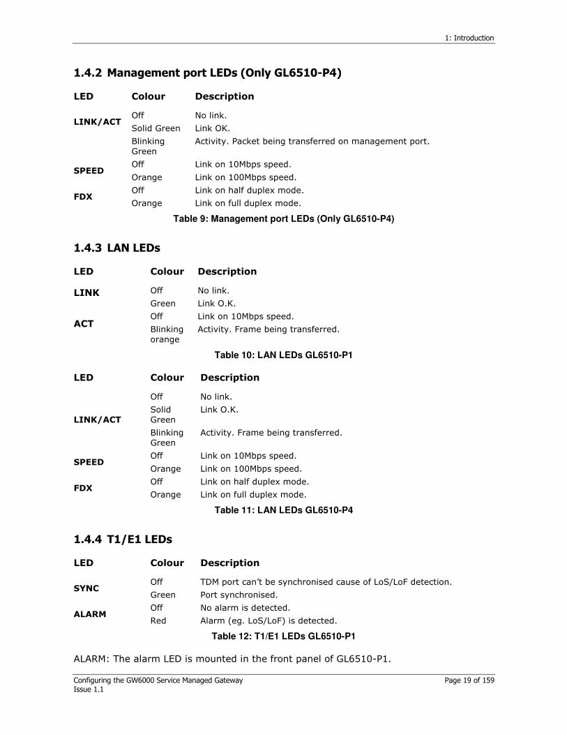
1.4.2 Management port LEDs (Only GL6510-P4) ............................................... 19
1.4.3 LAN LEDs ............................................................................................ 19
1.4.4 T1/E1 LEDs.......................................................................................... 19
2 Installing the GL6510............................................................................ 21
2.1 Checking the items before installing .................................................... 21
Power connection................................................................................................ 21
AC Input voltage AC100-240V, Input frequency is 50~60Hz............................... 21
System Location.................................................................................................. 21
2.2 Installing the system to the rack.......................................................... 21
3 System Management ............................................................................. 22
3.1 Using the console port.......................................................................... 22
3.2 Management via Telenet ...................................................................... 22
3.3 Management via the web ..................................................................... 23
3.4 Management via SNMP ......................................................................... 23
4 Command line interface: CLI ................................................................. 24
4.1 Booting the GL6510.............................................................................. 24
4.1.1 Initial screen........................................................................................ 24
4.1.2 Boot mode........................................................................................... 24
4.1.3 User mode........................................................................................... 25
4.1.4 Structure of commands ......................................................................... 26
4.2 CLI key conventions ............................................................................. 26

Table of Contents
Configuring the GW6000 Service Managed Gateway Page 6 of 159 Issue 1.1
4.2.1 Command completion ........................................................................... 26
4.2.2 Command abbreviation ......................................................................... 27
4.2.3 Context sensitive online help ................................................................. 27
4.2.4 Editing commands using keystrokes........................................................ 28
4.3 CLI Conventions ................................................................................... 29
4.4 CLI Tree .............................................................................................. 30
5 Configuring system information ............................................................ 32
5.1 System log on....................................................................................... 32
5.2 Top level commands............................................................................. 32
5.2.1 System network properties .................................................................... 33
5.2.2 Configuring system time........................................................................ 35
5.2.3 Configuring system information.............................................................. 35
5.2.4 System daemon process........................................................................ 37
5.2.5 System maintenance ............................................................................ 38
5.2.6 Displaying the system status ................................................................. 39
5.3 System image upgrade......................................................................... 40
Figure 8: Software upgrade via CLI or Telnet ...................................................... 41
6 Configuring the Ethernet port................................................................ 44
6.1 Commands for LAN configuration ......................................................... 44
6.2 Configuring the Ethernet (only uplink) trunk ....................................... 45
6.3 Displaying the LAN port statistic counter ............................................. 46
7 Configuring VLAN .................................................................................. 48
7.1 Commands for IEEE802.1Q Tagged VLAN............................................. 48
7.1.1 Tagged/untagged mode ........................................................................ 49
7.1.2 The advantage of a IEEE 802.1Q tagged VLAN ......................................... 49
7.1.3 PVID (Port VLAN ID) ............................................................................. 49
Figure 10: How to create a VLAN, adding/deleting a port, and removing a VLAN 50
7.2 CPU protection by VLAN ....................................................................... 52
Figure 12: Configuration of CPU accessible VLAN................................................ 52
8 Configuring spanning tree protocol ....................................................... 56
8.1 Spanning tree introduction................................................................... 56
8.2 Commands for spanning tree configuration.......................................... 56
8.3 Configuration examples using spanning tree protocol.......................... 57
9 Configuring Quality of Service (QoS)..................................................... 60
Figure 19: Packets in priority queues .................................................................. 60
9.1 Configuring QoS classification and status............................................. 60
9.2 Configuring classifying and scheduling ................................................ 61
9.3 Configuring the rate limit ..................................................................... 63
10 Configuring CES-TDM............................................................................. 65
10.1 CES-TDM Port configuration ................................................................. 65
PSN type diagrams.............................................................................................. 68
Continental type.................................................................................................. 68
Figure 25: Continental type PSN diagram............................................................ 68

Table of Contents
Configuring the GW6000 Service Managed Gateway Page 7 of 159 Issue 1.1
Dedicated type .................................................................................................... 68
Figure 26: Dedicated type PSN diagram .............................................................. 69
Loopback type ..................................................................................................... 69
Figure 27: Loopback type PSN diagram............................................................... 69
Metropolitan type................................................................................................ 69
Figure 28: Metropolitan type PSN diagram.......................................................... 69
10.2 Displaying CES-TDM interface .............................................................. 69
11 Configuring CES-PSN ............................................................................. 73
Figure 29: Configuring CES-PSN.......................................................................... 73
11.1 Configurating using the config ces-psn command ................................ 73
11.2 Configurating using the config ces-psn command ................................ 74
11.3 Clearing the CES-PSN packet counter................................................... 75
12 Configuring CES-Context ....................................................................... 76
12.1 Context configuration using set command ........................................... 76
12.2 Context configuration with config ces-context command ..................... 78
12.2.1 Frame mode/ RTP-PW type.................................................................... 78
12.2.2 Unframe mode/ RTP-PW type................................................................. 79
12.3 Displaying context status ..................................................................... 80
Figure 29: Example of context tx queue .............................................................. 87
13 Configuring SNMP.................................................................................. 88
13.1 SNMP Introduction ............................................................................... 88
Figure 30: Example of SNMP configurations ........................................................ 88
13.2 SNMP Commands ................................................................................. 88
14 Configuring NTP .................................................................................... 92
14.1 NTP configuration ................................................................................ 92
14.2 NTP Commands .................................................................................... 92
15 Configuring Access host ........................................................................ 94
15.1 Access host introduction ...................................................................... 94
15.1.1 Access host configuration commands ...................................................... 94
16 Monitoring via PMON counter ................................................................ 95
16.1 PMON counter ...................................................................................... 95
16.1.1 PMON commands ................................................................................. 95
17 Configuring SSL ..................................................................................... 99
17.1 Commands for SSL ............................................................................... 99
18 Loading profiles................................................................................... 100
18.1 Profile commands............................................................................... 100
Step 1 (GL6510-A CLI side): GL6510-A creates user-defined profile on GL6510-A.
............................................................................................................ 101
Step 2 (FTP server side): FTP server copies apple.conf from GL6510-A. ........... 101
Step 3 (GL6510-B,C side): GL6510-B,C loads ‘apple.conf’ from FTP server ....... 102
19 Configuring RMON ............................................................................... 104
19.1 RMON introduction ............................................................................. 104
19.2 RMON configuration ........................................................................... 104

Table of Contents
Configuring the GW6000 Service Managed Gateway Page 8 of 159 Issue 1.1
19.2.1 RMON History group control configuration ..............................................104
19.2.2 RMON alarm group/event control configuration .......................................105
19.3 RMON configuration example ............................................................. 107
19.3.1 RMON History group control configuration example..................................107
19.3.2 RMON alarm group/event control configuration example ..........................108
Appendix A: Configuring Clock mode................................................................. 112
1 GL6510 products introduction ........................................................................ 113
GL6510-P4 ....................................................................................................... 113
GL6510-P1 ....................................................................................................... 113
Available contexts............................................................................................ 113
Configuring the GW6510.................................................................................. 113
Step 1: assign IP to the system......................................................................... 113
Step 2: assign IP to CES-PSN port ..................................................................... 113
Step 3: configure CES-TDM................................................................................ 113
Step 4: configure CES-Context .......................................................................... 114
20 Examples based on TDM clock mode.................................................... 115
20.1 External-Adaptive clock in frame mode: Case I .................................. 116
Figure 39 Network diagram............................................................................... 116
20.1.1 Configuration steps using CLI................................................................116
21 Internal -Adaptive clock in frame mode: Case II ................................. 123
Figure 42: Network diagram.............................................................................. 123
21.1.1 CLI configuration.................................................................................123
Figure 43: GW6510 System’s network configuration......................................... 123
Figure 44: CES-PSN configuration ..................................................................... 124
Figure 45: CES-TDM configuration..................................................................... 126
Figure 46:.......................................................................................................... 126
21.2 Adaptive -Adaptive clock in frame mode: Case III ............................. 129
Figure 47: Network diagram.............................................................................. 129
21.2.1 CLI Configuration ................................................................................129
Figure 48: System’s network configuration....................................................... 129
Figure 49: CES-PSN configuration ..................................................................... 130
Figure 50: CES-TDM configuration..................................................................... 131
Figure 51: CES-Context configuration ............................................................... 133
Figure 52:.......................................................................................................... 134
21.3 Loopback-Adaptive clock in unframe mode: Case IV .......................... 135
Figure 53: Network diagram.............................................................................. 135
21.3.1 CLI Configuration ................................................................................135
Figure 54: System network configuration ......................................................... 135
Figure 56:.......................................................................................................... 138
Figure 57:.......................................................................................................... 139
21.4 Internal-Adaptive avg clock in unframe mode: Case V ....................... 140
Figure 58: Network diagram.............................................................................. 140
Figure 59: CES-context setup ............................................................................ 141

Table of Contents
Configuring the GW6000 Service Managed Gateway Page 9 of 159 Issue 1.1
Figure 60: CES-PSN configuration ..................................................................... 142
Figure 61: CES-TDM configuration..................................................................... 143
21.5 Differential-Differential clock in unframe mode: Case VI ................... 145
Figure 62: Network diagram.............................................................................. 145
21.5.1 CLI configuration.................................................................................145
Figure 63: System network configuration ......................................................... 145
Figure 64: CES-PSN configuration ..................................................................... 146
Figure 65:CES-TDM setup .................................................................................. 148
Figure 66:.......................................................................................................... 148
Figure 67: CES context setup ............................................................................ 149
Figure 68:CES-context setup ............................................................................. 150
21.6 Adaptive-Adaptive clock in unframe mode: Case VII.......................... 151
Figure 69: Network diagram.............................................................................. 151
21.6.1 CLI configuration.................................................................................151
Figure 70: System network configuration ......................................................... 151
Figure 71:CES-PSN configuration ...................................................................... 152
Figure 72: CES-TDM configuration..................................................................... 153
Figure 73:.......................................................................................................... 154
Figure 74:.......................................................................................................... 155
Figure 75:.......................................................................................................... 156
22 Troubleshooting .................................................................................. 157
22.1 Configuring system information warning and error messages ........... 157
22.2 Configuring Context using set command error messages................... 158
22.3 SNMP Configuration warning and error messages.............................. 159
22.4 NTP configuration warning and info messages................................... 159

1: Introduction
Configuring the GW6000 Service Managed Gateway Page 10 of 159 Issue 1.1
1 Introduction
High-speed packet (IP, VPN, ATM…) based networks are the latest innovation in the world of communications. The capacity of these networks is increasing rapidly, fuelled by the popularity of the Internet and decreasing costs associated with the technology.
Worldwide data traffic volume has already surpassed that of the telephone network, and for many applications, the price of IP traffic has dropped below the traffics associated with traditional TDM services. Consequently, significant effort is being expended on VoIP technologies. Inherent revolutionary change in all forms of VoIP is where much of the existing telephony infrastructure will be replaced by new IP-based mechanisms. Despite the hype, this effort has been more protracted and less successful than initially expected.
Today's telephony technology is extremely complex, both those portions that VoIP aims to replace and those to which VoIP must interface. Revolutionary implementations of its hundreds of features and thousands of variations cannot be expected to be developed in a short time frame.
There is, however, an alternative method of exploiting IP networks for telephony service that is evolutionary rather than revolutionary. This method uses IP networks as a drop-in replacement for native TDM networks. It seamlessly interfaces to all existing equipment, such as legacy PBXs and switches, and inherently provides all the hundreds of telephony features and the PSTN quality to which customers have become accustomed. This alternative is circuit extension over IP using GL6510.
1.1 The CESoPSN concept
The increase in access and edge network transport is forcing service providers to consider other cost effective transport mechanisms. Circuit switched transport mechanisms, T1/E1 and SDH/SONET have been the core of the voice network. With the evolution of ubiquitous packet networks, efforts are being made to transport voice over the packet switched network.
Circuit Emulation Services over Packet Switched Networks (CESoPSN) transport digital trunks such as T1/E1 and SDH/SONET circuits over packet networks such as IP or ATM. There are challenges in realizing virtual circuits over packet networks, with interfaces satisfying the same performance characteristics as the circuit switched networks.
Packet Switched
Network
IP, ATM T1/E1
Circuit
Network
Circuit Network
T1/E1
Figure 1: Concept of CESoPSN
1: Introduction
Configuring the GW6000 Service Managed Gateway Page 11 of 159 Issue 1.1
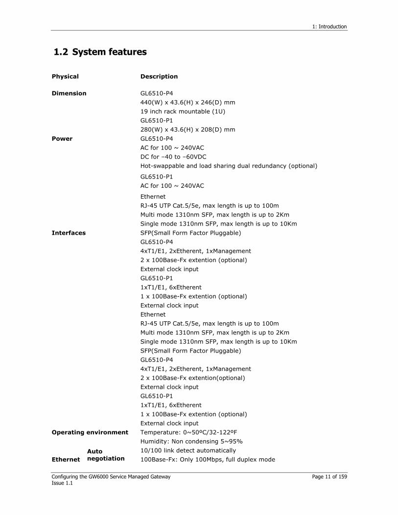
1.2 System features
Physical Description
GL6510-P4
440(W) x 43.6(H) x 246(D) mm
19 inch rack mountable (1U)
Dimension
GL6510-P1
280(W) x 43.6(H) x 208(D) mm
GL6510-P4
AC for 100 ~ 240VAC
DC for –40 to –60VDC
Hot-swappable and load sharing dual redundancy (optional)
Power
GL6510-P1
AC for 100 ~ 240VAC
Ethernet
RJ-45 UTP Cat.5/5e, max length is up to 100m
Multi mode 1310nm SFP, max length is up to 2Km
Single mode 1310nm SFP, max length is up to 10Km
SFP(Small Form Factor Pluggable)
GL6510-P4
4xT1/E1, 2xEtherent, 1xManagement
2 x 100Base-Fx extention (optional)
External clock input
GL6510-P1
1xT1/E1, 6xEtherent
1 x 100Base-Fx extention (optional)
External clock input
Ethernet
RJ-45 UTP Cat.5/5e, max length is up to 100m
Multi mode 1310nm SFP, max length is up to 2Km
Single mode 1310nm SFP, max length is up to 10Km
SFP(Small Form Factor Pluggable)
GL6510-P4
4xT1/E1, 2xEtherent, 1xManagement
2 x 100Base-Fx extention(optional)
External clock input
Interfaces
GL6510-P1
1xT1/E1, 6xEtherent
1 x 100Base-Fx extention (optional)
External clock input
Operating environment Temperature: 0~50ºC/32-122ºF
Humidity: Non condensing 5~95%
Ethernet
Auto negotiation
10/100 link detect automatically
100Base-Fx: Only 100Mbps, full duplex mode
1: Introduction
Configuring the GW6000 Service Managed Gateway Page 12 of 159 Issue 1.1
Flow control IEEE802.3x in full duplex mode
Back pressure in half duplex mode
Auto MDI-X Supported on only Auto negotiation mode.
Connector Balanced (120 Ω): RJ-48c (8pin)
Unbalanced (75Ω): Balun (RJ-48c to BNC, Optional)
Line interface ITU-T G.703
Line impedance
Balanced 120Ω
Unbalanced 75Ω
Framing mode
Unframed (default)
Frame
Framing CRC4 MF (both CAS and CCS)
Line coding HDB3 (default)
AMI
Line rate 2.048Mbps (± 50ppm)
E1
Jitter/wander
performance
ITU-T G.823
Line interface
ITU-T G.703
ANSI
T1.102
T1.403
AT&T TR62411
ETSI 300-011
Line impedance
Balanced 100 Ω
Framing mode
Unframed (default)
Frame
Framing
ESF (default)
SF
SLC96
T1-DM
Japanese TTC JT-G704
Line coding B8ZS(default)
AMI
Line rate 1.544Mbps (± 32ppm)
T1
Jitter/wander performance
AT&T TR-62411
ITU-T G.824
Connector DB-9 type
Alarm
Signal
Major alarm
Minor alarm
Remote alarm clear
*Only supported in GL6510-P4

1: Introduction
Configuring the GW6000 Service Managed Gateway Page 13 of 159 Issue 1.1
Common Description
Multi-protocol encapsulation
IP/UDP/RTP-PW (IPv4 only)
MPLS/MEF-PW
Compliant with:
Latest IETF PWE3 MPLS forum
MEF circuit emulation standards
PWE3- Pseudo Wired Emulation End to End(Based on IETF)
MEF- Metro Ethernet Forum(Based on MEF2.0)
End-to-end delay 0.625ms + network delay
Packet size Max. 1522 Bytes with VLAN tag
Clock mode
Loopback
Internal
External
Adaptive
Differential(in-band)
System Description
Syslog(remote/local log)
256 log messages
1024 backup messages
NTP RFC 1305
Access host Max. 10 entries
System management Description
Console Local console port: RS-232
Telnet Max. 4 sessions
SNMP agent SNMP v1/v2c
HTTP Web GUI Web-based management
Image upgrade Image upgrade via FTP/TFTP interface
Standard conformation Description
SNMP IEEE 802.1Q VLAN tagging
IEEE 802.1p priority
IEEE 802.3x flow control
IEEE 802.3/802.3u
RFC 1157 (SNMP v1/v2c)
RFC 1643 (Ethernet-like MIB)
RFC 1213 (MIB-II)
RFC 2819 (RMON Group 1,2,3,9)
RFC 791 (IP)
RFC 792(ICMP)
RFC 826 (ARP)

1: Introduction
Configuring the GW6000 Service Managed Gateway Page 14 of 159 Issue 1.1
E1 ITU-T Rec
G.703
G.704
G.706
G.711
G.732
G.755
G.796
G.823
I.431
T1 AT&T
TR62411
ITU-T Rec.
G.703
G.704
G.802
G.824
ANSI
T1.403
Telcordia
GR-303-CORE
TTC
JT-G703
JT-G704
Table 1: System features
1.3 System appearance
1.3.1 Front panel description
1.3.1.1 System LEDs
The GL6510’ system LED shows the status of system power, fan operating and that the system is functioning properly. Section 1.4.1 LED indicators, describes the LED colors and their meanings.
1.3.1.2 : Console port
You can connect the system to a PC via console port, An RJ-45 to DB-9 female DTE adapter cable is provided to connect the system.
Console port pinout(GL6510) Serial port pinout(PC)
1 Reserved 1 NC (Not connected)
2 Reserved 2 TXD
3 TXD (from GL6510) 3 RXD
4 GND 4 Reserved
5 GND 5 GND
1: Introduction
Configuring the GW6000 Service Managed Gateway Page 15 of 159 Issue 1.1
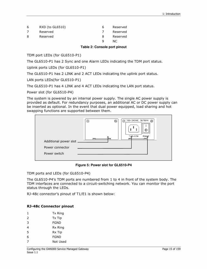
6 RXD (to GL6510) 6 Reserved
7 Reserved 7 Reserved
8 Reserved 8 Reserved
9 NC
Table 2: Console port pinout
TDM port LEDs (for GL6510-P1)
The GL6510-P1 has 2 Sync and one Alarm LEDs indicating the TDM port status.
Uplink ports LEDs (for GL6510-P1)
The GL6510-P1 has 2 LINK and 2 ACT LEDs indicating the uplink port status.
LAN ports LEDs(for GL6510-P1)
The GL6510-P1 has 4 LINK and 4 ACT LEDs indicating the LAN port status.
Power slot (for GL6510-P4)
The system is powered by an internal power supply. The single AC power supply is provided as default. For redundancy purposes, an additional AC or DC power supply can be inserted as optional. In the event that dual power equipped, load sharing and hot swapping functions are supported between them.
Additional power slot Power connector
Power switch
Figure 5: Power slot for GL6510-P4
TDM ports and LEDs (for GL6510-P4)
The GL6510-P4’s TDM ports are numbered from 1 to 4 in front of the system body. The TDM interfaces are connected to a circuit-switching network. You can monitor the port status through the LEDs.
RJ-48c connector’s pinout of T1/E1 is shown below:
RJ-48c Connector pinout
1 Tx Ring
2 Tx Tip
3 FGND
4 Rx Ring
5 Rx Tip
6 FGND
7 Not Used

1: Introduction
Configuring the GW6000 Service Managed Gateway Page 16 of 159 Issue 1.1
8 Not Used
Table 3: TDM ports and LEDs (for GL6510-P4)
External clock (for GL6510-P4)
The external clock port can only receive a clock from an external source. When a TDM clock is external or in differential mode, an external clock must be connected to this port.
Uplink ports and LEDs (for GL6510-P4)
The GL6510-P4 has 2 uplink ports that connect to the PSN(Packet Switched Network) to exchange encapsulated TDM data. For a 100Base-Fx connection insert the relevent option module to uplink the interface. As factory default, 10/100Base-Tx ports are supplied as uplink interfaces. To use 100Base-Fx change the configuration. See section 6: Configuring the Ethernet Port.
10/100Base-Tx port
100Base-Fx slot
Figure 6: 10/100Base-Tx or 100Base-Fx are used exclusively
RJ-45 connector pinout
1 TX+
2 TX-
3 RX+
4 Not used
5 Not used
6 RX-
7 Not used
8 Not used
Table 4: RJ-45 connector pinout
Alternative option slot
100Base-Fx- multi mode 1310nm, 2Km SFP type
100Base-Fx- 62.5/125µm single mode 1310nm, 10Km
Table 5: Alternative option slot
Only 10/100Base-Tx RJ-45 module(s) are supplied. 100Base-Fx module(s) are not supplied.
Management ports (for GL6510-P4)

1: Introduction
Configuring the GW6000 Service Managed Gateway Page 17 of 159 Issue 1.1
GL6510-P4 is managed remotely using ‘Management port’via telnet or WEB GUI.
1.3.2 Rear panel description
LAN ports (for GL6510-P1)
The GL6510-P1 has four LAN ports for using an Ethernet network.
Uplink ports (for GL6510-P1)
The GL6510-P1 has two uplink ports for PSN. LAN data (from LAN ports) and encapsulated TDM data (from TDM ports) are converged into PSN through the uplink port.
Optional uplink 100Base-Fx extension (for GL6510-P1)
The GL6510-P1 has two uplink ports for connecting to a PSN(Packet Switched Network) to exchange encapsulated TDM data. For a 100Base-Fx connection, insert the relevent option module into the Uplink2 Interface to only uplink two interfaces.
As factory default, 10/100Base-Tx ports are supplied as uplink interfaces. To use 100Base-Fx, change the configuration. See section 6: Configuring the Ethernet Port.
TDM ports (for GL6510-P1)
The GL6510-P1’s TDM ports are numbered from 1 to 4 in front of the system body. The TDM interfaces are connected to a circuit-switching network. You can monitor the port status through the LEDs.
RJ-48c connector’s pinout of T1/E1 is shown below:
RJ-48c Connector Pinout
1 Tx Ring
2 Tx Tip
3 FGND
4 Rx Ring
5 Rx Tip
6 FGND
7 Not Used
8 Not Used
Table 6: RJ-48 connector pinout
External clock port (for GL6510-P1)
The external clock port can only receive a clock from an external source. When a TDM clock is external or in differential mode, this external clock port is mandated over others. An external clock must be connected to this port.
Power connector & switch (for GL6510-P1)
The device is powered by an internal power supply. Only a single AC power supply can be used as there is no redundant power supply.

1: Introduction
Configuring the GW6000 Service Managed Gateway Page 18 of 159 Issue 1.1
Alarm Port (Dry contact, for GL6510-P4 only)
The GL6510-P4 has alarm ports in the real panel of the system to connect to the Central Alarm Monitoring System (CAMS). In this case, a DB9 cable is required between the CAMS and the device.
Alarm DB-9 Connector pinout
1 Discrete Line input
2 Discrete Line input
3 Major alarm Common contact
4 Major alarm Normally open
5 Minor alarm Common contact
6 Discrete Line input
7 Discrete Line input
8 GND -
9 Minor alarm Normally open
Table 7: Alarm DB-9 Connector pinout
When a major alarm occurs, the relay between pin 3 and 4 is closed. When a minor alarm occurs, the relay between pin 5 and 9 is closed.
The following alarm features are not implemented in software version 1.0
- Major alarm displays
- LoS/LoF
- AIS
- RAI
- Minor alarm displays
- LAN link down
- LAN link up
1.4 LED indicators
The unit’s LEDs are used to monitor system activity and its status. The tables below explain the LED colours and their meanings.
1.4.1 System LEDs
LED Colour Description
Off System is not powered. Power
Green System is powered on.
Off System is receiving power but is not functioning properly. RUN
Green System is operating normally.
Off System fans are operating normally. FAN
Red Shows a fan failure
Table 8: System LEDs
1: Introduction
Configuring the GW6000 Service Managed Gateway Page 19 of 159 Issue 1.1
1.4.2 Management port LEDs (Only GL6510-P4)
LED Colour Description
Off No link. LINK/ACT
Solid Green Link OK.
Blinking Green
Activity. Packet being transferred on management port.
Off Link on 10Mbps speed. SPEED
Orange Link on 100Mbps speed.
Off Link on half duplex mode. FDX
Orange Link on full duplex mode.
Table 9: Management port LEDs (Only GL6510-P4)
1.4.3 LAN LEDs
LED Colour Description
Off No link. LINK Green Link O.K.
Off Link on 10Mbps speed. ACT
Blinking orange
Activity. Frame being transferred.
Table 10: LAN LEDs GL6510-P1
LED Colour Description
Off No link.
Solid Green
Link O.K. LINK/ACT
Blinking Green
Activity. Frame being transferred.
Off Link on 10Mbps speed. SPEED
Orange Link on 100Mbps speed.
Off Link on half duplex mode. FDX
Orange Link on full duplex mode.
Table 11: LAN LEDs GL6510-P4
1.4.4 T1/E1 LEDs
LED Colour Description
Off TDM port can’t be synchronised cause of LoS/LoF detection. SYNC
Green Port synchronised.
Off No alarm is detected. ALARM
Red Alarm (eg. LoS/LoF) is detected.
Table 12: T1/E1 LEDs GL6510-P1
ALARM: The alarm LED is mounted in the front panel of GL6510-P1.
1: Introduction
Configuring the GW6000 Service Managed Gateway Page 20 of 159 Issue 1.1
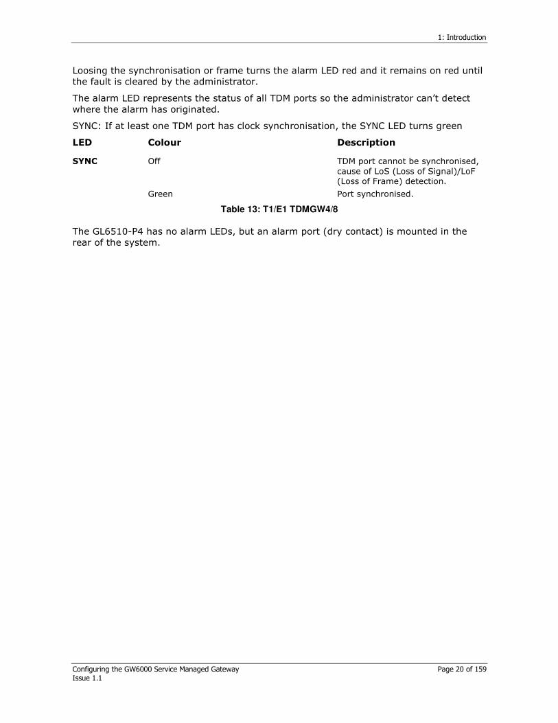
Loosing the synchronisation or frame turns the alarm LED red and it remains on red until the fault is cleared by the administrator.
The alarm LED represents the status of all TDM ports so the administrator can’t detect where the alarm has originated.
SYNC: If at least one TDM port has clock synchronisation, the SYNC LED turns green
LED Colour Description
Off TDM port cannot be synchronised, cause of LoS (Loss of Signal)/LoF (Loss of Frame) detection.
SYNC
Green Port synchronised.
Table 13: T1/E1 TDMGW4/8
The GL6510-P4 has no alarm LEDs, but an alarm port (dry contact) is mounted in the rear of the system.

2: Installing the GL6510
Configuring the GW6000 Service Managed Gateway Page 21 of 159 Issue 1.1
2 Installing the GL6510
2.1 Checking the items before installing
The GL6510-P1 stands by itself on a flat table but the GL6510-P4 is stacked in a 19 inch rack. Ensure an optimal environment for installing the system, such as the correct power requirement, enough physical space, and easy access to other network devices.
Please read and follow the points below when installing the GL6510 for a safe and comfortable user environment.
Power connection
AC Input voltage AC100-240V, Input frequency is 50~60Hz
DC Input voltage DC –40 ~ –60V
Power consumption is 30Watts maximum.
The power supply is regulated automatically by the input voltage.
Do not overload the power line.
System Location
Check the parts and relevant tools before installing the system on to the rack.
Put the system in a cool and dry area.
Ensure there is at least 10cm of space of between the wall surface and the system, for good ventilation.
Avoid direct light, electrical interferences, and high temperatures.
Put the system in an area where the cables can be connected easily.
Take precautions against electric shock.
After connecting the power to the system, do not touch the system while wearing metallic accessories.
Do not touch the main board, the components of the option board and the pins of the connector.
Use the anti-electric shock package to keep the system and components in.
Keep the option board facing up after removing it from the system.
2.2 Installing the system to the rack
Use the bracket and screws provided with the system.
Attach the bracket to the each side of the GL6510-P4 using a screw driver.
Align the bracket hole and the rack hole and set the GL6510-P14 into the rack.
Fix the bracket to the rack with the screws provided.

3: System Management
Configuring the GW6000 Service Managed Gateway Page 22 of 159 Issue 1.1
3 System Management
3.1 Using the console port
The GL6510 provides a console port for system management. The console port controls the GL6510 through serial communication. An emulator such as ‘hyper terminal’ is necessary for serial communication with a console port.
Connect one end of the RS-232 cable to the serial port of the terminal and the other end of the cable to the CONSOLE port on the front side of the GL6510.
Set up the serial communication emulator in the same way.
Parameters Value
Baud Rate 9600bps
Data Bit 8 bit
Stop Bit 1 bit
Parity Bit None
Flow Control Off
Table 14: Default console port parameter values
The console cable is a straight cable type, with an RJ-45 at one end and a DB-9 connector at the other.
Figure 15: Console jack (to GL6510) Figure 16: Serial jack (to PC)
Console side Serial side Description
1 8 Reserved
2 6 Reserved
3 2 TxD (From GW6000)
4 5 GND
5 5 GND
6 3 RxD (To GW6000)
7 4 Reserved
8 7 Reserved
Table 15: Console Cable Pinouts
3.2 Management via Telenet
The GL6510 provides a remote management system using the CLI via telnet. You can control the GL6510 remotely if you set up a telnet communication between a remote host and the GL6510’s management port (Ethernet) via a network interface.

3: System Management
Configuring the GW6000 Service Managed Gateway Page 23 of 159 Issue 1.1
First enter an IP address of the same subnet group as the host via the console, and then connect the Ethernet port of the system to the remote host using a UTP cable. The Telnet interface configuration and functionality is the same as the console management interface. Up to four Telnet sessions can be established simultaneously.
3.3 Management via the web
The GL6510 provides web management. You can manage the GL6510 via a web browser (Internet Explorer or Netscape) after entering a system IP address in the same way using Telnet and then connecting to the Ethernet port of the remote host using a UTP cable.
3.4 Management via SNMP
You can manage the GL6510 via the SNMP manager (NMS) if you enter the IP address of the SNMP manager (NMS) as an IP Trap manager (the IP address of the SNMP Manager) via the CLI. SNMP allows you to manage the system such as monitoring statistics for counters on the remote network station and setting the configurable parameters.

4: Command line interface: CLI
Configuring the GW6000 Service Managed Gateway Page 24 of 159 Issue 1.1
4 Command line interface: CLI
4.1 Booting the GL6510
4.1.1 Initial screen
The example below shows the initial screen that appears when booting the GL6510 system for the first time. After the booting sequence is finished completely, the system issues a prompt to log in.
GW6000 Boot v1.0 (60 MHz)
DRAM : 64 MB
FLASH : 32 MB
Hit 'ESC' key to stop autoboot: 0
>>>>>>>>>>>>>>>>>>>>>>>>>>>>>>>>>>>>>>>>>>>>>>>>>>>>>>>>>>>>>e
th0: FEC ENET Ver0
Uncompressing image...
>>>>>>>>>>>>>>>>>>>>>>>>>>>>
####### ###### # # ##### # #
# # # ## ## # # # # #
# # # # # # # # # # #
# # # # # # ##### # #### # # #
# # # # # # # # # #
# # # # # # # # # #
# ###### # # ##### ## ##
GW6000 login: root
Welcome to TDM Gateway.
GW6000#
Figure 16: Initial screen
4.1.2 Boot mode
Boot mode provides an additional function, a simple hardware test and recovery function that the OS image and the file system image from the Flash memory when they crash.
Boot supports both a user mode and an administrator mode. User mode allows all basic commands. Administrator mode is for all basic commands and also the programmer’s debugging command. To use all other functions, select user mode.
4: Command line interface: CLI
Configuring the GW6000 Service Managed Gateway Page 25 of 159 Issue 1.1
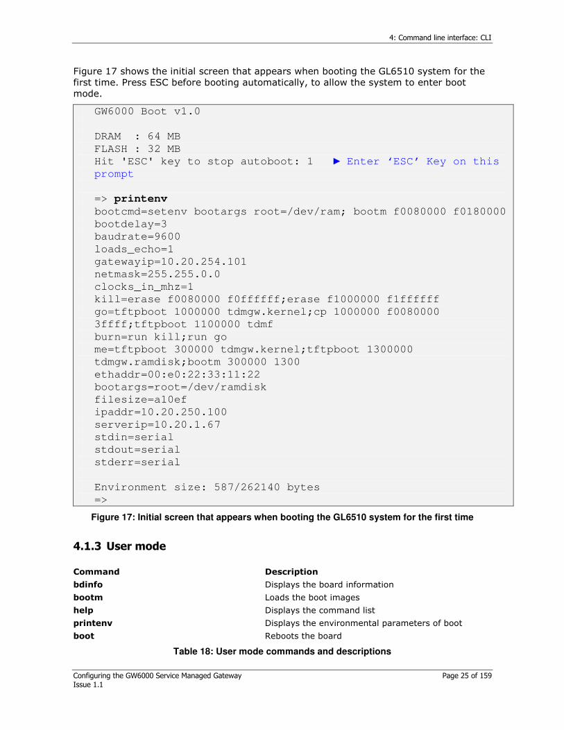
Figure 17 shows the initial screen that appears when booting the GL6510 system for the first time. Press ESC before booting automatically, to allow the system to enter boot mode.
GW6000 Boot v1.0
DRAM : 64 MB
FLASH : 32 MB
Hit 'ESC' key to stop autoboot: 1 Enter ‘ESC’ Key on this
prompt
=> printenv
bootcmd=setenv bootargs root=/dev/ram; bootm f0080000 f0180000
bootdelay=3
baudrate=9600
loads_echo=1
gatewayip=10.20.254.101
netmask=255.255.0.0
clocks_in_mhz=1
kill=erase f0080000 f0ffffff;erase f1000000 f1ffffff
go=tftpboot 1000000 tdmgw.kernel;cp 1000000 f0080000
3ffff;tftpboot 1100000 tdmf
burn=run kill;run go
me=tftpboot 300000 tdmgw.kernel;tftpboot 1300000
tdmgw.ramdisk;bootm 300000 1300
ethaddr=00:e0:22:33:11:22
bootargs=root=/dev/ramdisk
filesize=a10ef
ipaddr=10.20.250.100
serverip=10.20.1.67
stdin=serial
stdout=serial
stderr=serial
Environment size: 587/262140 bytes
=>
Figure 17: Initial screen that appears when booting the GL6510 system for the first time
4.1.3 User mode
Command Description
bdinfo Displays the board information
bootm Loads the boot images
help Displays the command list
printenv Displays the environmental parameters of boot
boot Reboots the board
Table 18: User mode commands and descriptions

4: Command line interface: CLI
Configuring the GW6000 Service Managed Gateway Page 26 of 159 Issue 1.1
=> setenv ipaddr 10.20.77.88
=> setenv server 10.20.1.1
=> saveenv
Saving Environment to Flash...
Un-Protected 1 sectors
Erasing Flash...
.
Done
OK
Writing to Flash... done
Protected 1 sectors
Figure 18: Screen showing user mode
4.1.4 Structure of commands
CONFIG mode consists of system setting commands.
Use the # key for CONFIG mode.
Operation + Function + Destination or Index + Feature or Parameters + Value or mode (type).
Command Description
Operation Displays target information. For example, commands such as show and set.
Function System functions such as ces-tdm, snmp
Destination or index
Port number or index. For example, eth port 1 or
ces-context 1.
Feature or parameters
Detailed features or parameters. For example, eth
port 1 port flow-control or ces-context 1 jitter buffer 1000.
Value or type
Detailed features or parameters. For example, eth
port 1 port flow-control on or ces-context 1 jitter buffer 1000.
Table 19: Description of commands
4.2 CLI key conventions
GL6510’s CLI provides key conventions such as command completion, command abbreviation, and context sensitive online help using the “?” key.
4.2.1 Command completion
Use the <TAB> key for the command completion function.
Enter the first characters of the command and press < TAB>. The entered command is completed automatically without having to type the remaining part of the command.
4: Command line interface: CLI
Configuring the GW6000 Service Managed Gateway Page 27 of 159 Issue 1.1
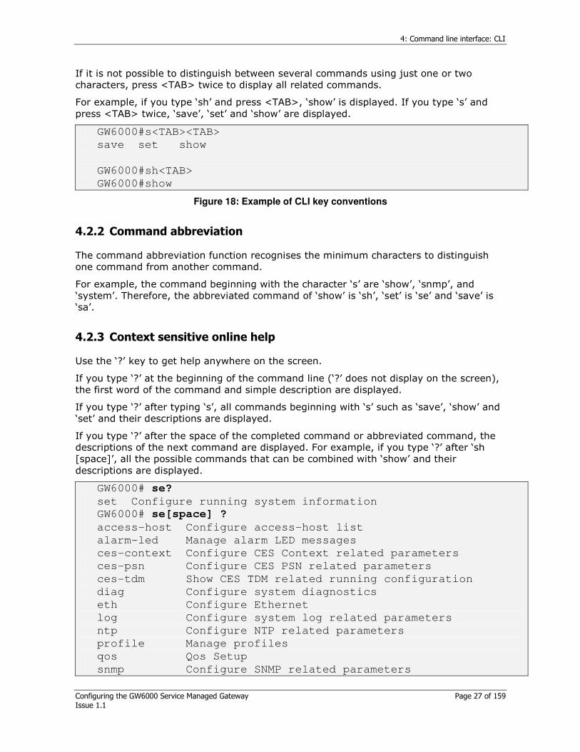
If it is not possible to distinguish between several commands using just one or two characters, press <TAB> twice to display all related commands.
For example, if you type ‘sh’ and press <TAB>, ‘show’ is displayed. If you type ‘s’ and press <TAB> twice, ‘save’, ‘set’ and ‘show’ are displayed.
GW6000#s<TAB><TAB>
save set show
GW6000#sh<TAB>
GW6000#show
Figure 18: Example of CLI key conventions
4.2.2 Command abbreviation
The command abbreviation function recognises the minimum characters to distinguish one command from another command.
For example, the command beginning with the character ‘s’ are ‘show’, ‘snmp’, and ‘system’. Therefore, the abbreviated command of ‘show’ is ‘sh’, ‘set’ is ‘se’ and ‘save’ is ‘sa’.
4.2.3 Context sensitive online help
Use the ‘?’ key to get help anywhere on the screen.
If you type ‘?’ at the beginning of the command line (‘?’ does not display on the screen), the first word of the command and simple description are displayed.
If you type ‘?’ after typing ‘s’, all commands beginning with ‘s’ such as ‘save’, ‘show’ and ‘set’ and their descriptions are displayed.
If you type ‘?’ after the space of the completed command or abbreviated command, the descriptions of the next command are displayed. For example, if you type ‘?’ after ‘sh [space]’, all the possible commands that can be combined with ‘show’ and their descriptions are displayed.
GW6000# se?
set Configure running system information
GW6000# se[space] ?
access-host Configure access-host list
alarm-led Manage alarm LED messages
ces-context Configure CES Context related parameters
ces-psn Configure CES PSN related parameters
ces-tdm Show CES TDM related running configuration
diag Configure system diagnostics
eth Configure Ethernet
log Configure system log related parameters
ntp Configure NTP related parameters
profile Manage profiles
qos Qos Setup
snmp Configure SNMP related parameters

4: Command line interface: CLI
Configuring the GW6000 Service Managed Gateway Page 28 of 159 Issue 1.1
swconf manage switch configuration file
system Configure system related parameters
user Define user information
Figure 19: Example of command combinations
<cr> is displayed when all commands match the condition. Then press the ‘Enter’ key
When you type ‘?’, use commands beginning with a lowercase letter as input commands.
When you type ‘?’ use commands beginning with a capital letter as variables.
4.2.4 Editing commands using keystrokes
Key Function
Ctrl+f Shifts one character to the right
Ctrl+b Shifts one character to the left
Ctrl+a Shifts to the head of the command line
Ctrl+e Shifts to the end of the command line
Ctrl+h Deletes the character before the cursor
Ctrl+w Deletes the word before the cursor
Ctrl+k Deletes from the cursor to the end of the command line
Ctrl+u Deletes at the cursor point before the command line
Ctrl+t Switches the character before the cursor with the character at the cursor
Ctrl+n Shifts to the next line of the history buffer (the same function as the arrow key ‘↓’)
Ctrl+p Shifts to the previous line of the history buffer (the same function as the arrow key ‘↑’)
↓↓↓↓ Shifts to the next line of the history buffer (ctrl+n)
↑↑↑↑ Shifts to the previous line of the history buffer (ctrl+p)
<TAB> Completes the command
? Displays available Command at that point with a simple description.
Table 20: Editing commands using key strokes
Communication emulators such as “hyper terminal” are not able to search the command saved in the history buffer using the arrow keys (‘↑’, ‘↓’). This is because the arrow keys are mapped to other keys on the emulator itself. It is recommended you use the latest emulator version to allow key mapping.
4: Command line interface: CLI
Configuring the GW6000 Service Managed Gateway Page 29 of 159 Issue 1.1
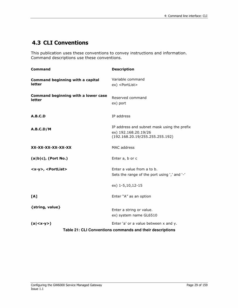
4.3 CLI Conventions
This publication uses these conventions to convey instructions and information. Command descriptions use these conventions.
Command Description
Command beginning with a capital letter
Variable command
ex) <PortList>
Command beginning with a lower case letter
Reserved command
ex) port
A.B.C.D
IP address
A.B.C.D/M
IP address and subnet mask using the prefix
ex) 192.168.20.19/26 (192.168.20.19/255.255.255.192)
XX-XX-XX-XX-XX-XX
MAC address
(a|b|c), (Port No.)
Enter a, b or c
<x-y>, <PortList>
Enter a value from a to b.
Sets the range of the port using ‘,’ and ‘-’
ex) 1-5,10,12-15
[A]
Enter “A” as an option
string, value
Enter a string or value.
ex) system name GL6510
(a|<x-y>) Enter ‘a’ or a value between x and y.
Table 21: CLI Conventions commands and their descriptions
4: Command line interface: CLI
Configuring the GW6000 Service Managed Gateway Page 30 of 159 Issue 1.1
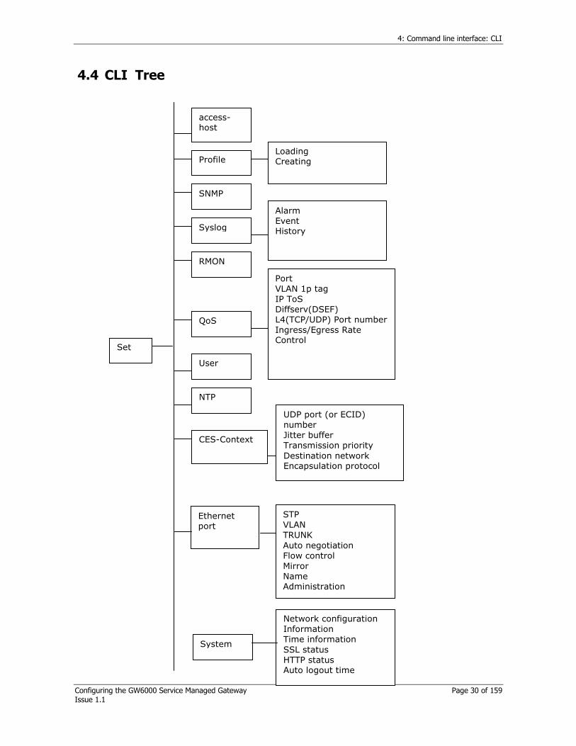
4.4 CLI Tree
Set
System
Network configuration Information Time information SSL status HTTP status Auto logout time
Ethernet port
STP VLAN TRUNK Auto negotiation Flow control Mirror Name Administration
NTP
User
SNMP
CES-Context
UDP port (or ECID) number Jitter buffer Transmission priority Destination network Encapsulation protocol
QoS
Port VLAN 1p tag IP ToS Diffserv(DSEF) L4(TCP/UDP) Port number Ingress/Egress Rate Control
Syslog
Alarm Event History
Profile Loading Creating
access-host
RMON
4: Command line interface: CLI
Configuring the GW6000 Service Managed Gateway Page 31 of 159 Issue 1.1
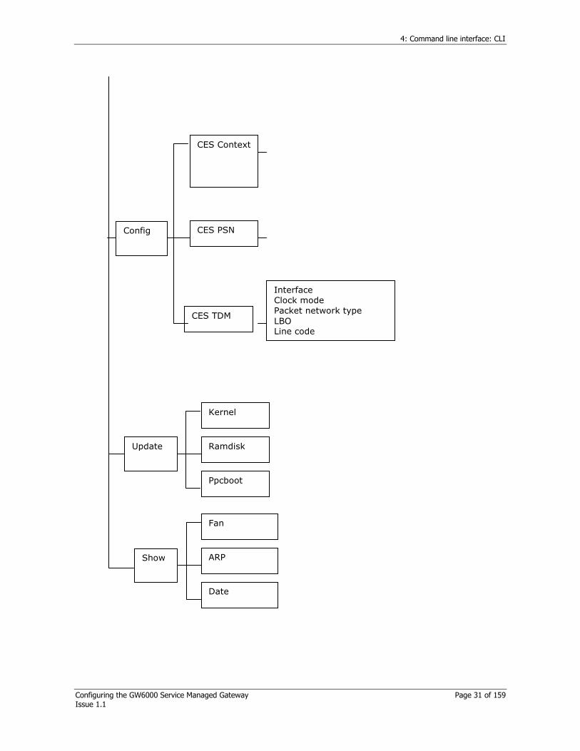
Update
Kernel
Ramdisk
Ppcboot
Show
Fan
ARP
Date
Config
CES Context
CES TDM
CES PSN
Interface Clock mode Packet network type LBO Line code
5: Configuring system information
Configuring the GW6000 Service Managed Gateway Page 32 of 159 Issue 1.1
5 Configuring system information
5.1 System log on
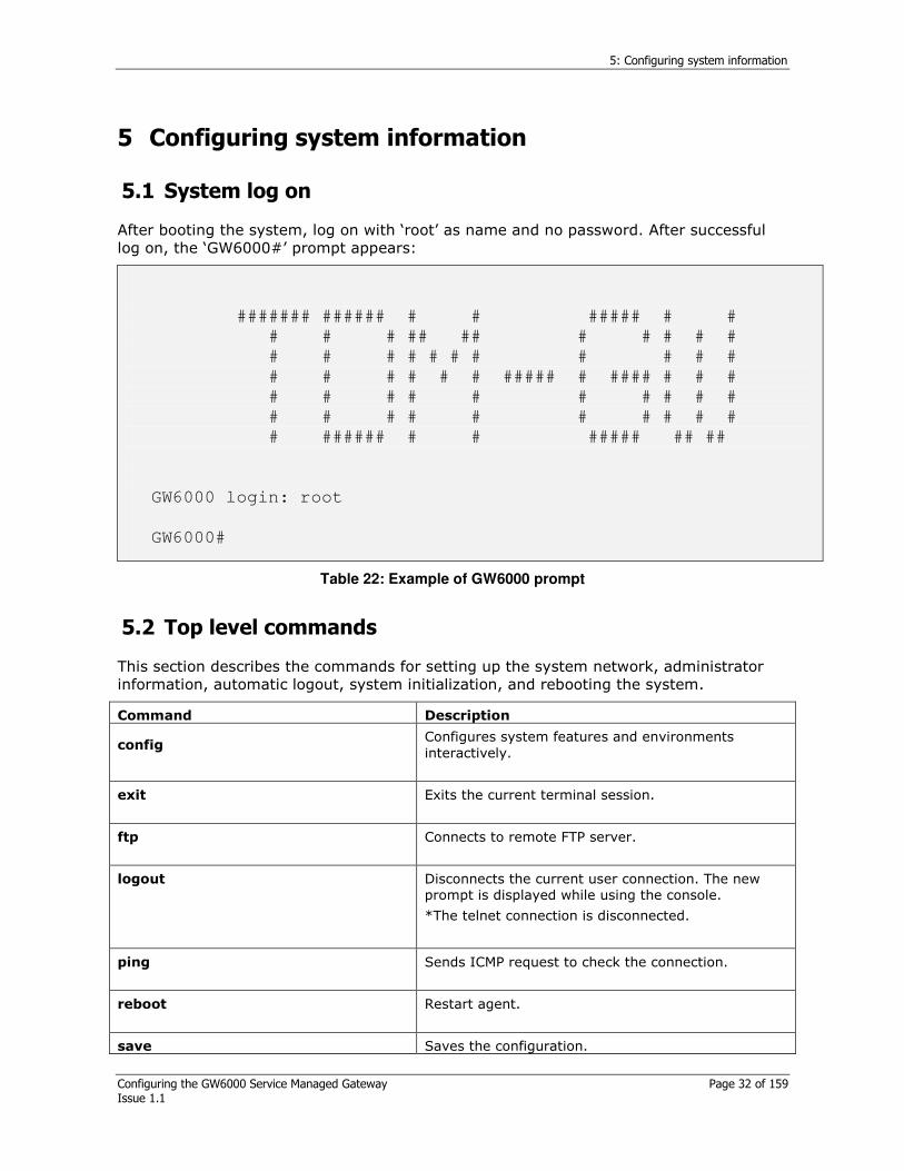
After booting the system, log on with ‘root’ as name and no password. After successful log on, the ‘GW6000#’ prompt appears:
####### ###### # # ##### # #
# # # ## ## # # # # #
# # # # # # # # # # #
# # # # # # ##### # #### # # #
# # # # # # # # # #
# # # # # # # # # #
# ###### # # ##### ## ##
GW6000 login: root
GW6000#
Table 22: Example of GW6000 prompt
5.2 Top level commands
This section describes the commands for setting up the system network, administrator information, automatic logout, system initialization, and rebooting the system.
Command Description
config
Configures system features and environments interactively.
exit
Exits the current terminal session.
ftp
Connects to remote FTP server.
logout
Disconnects the current user connection. The new prompt is displayed while using the console.
*The telnet connection is disconnected.
ping
Sends ICMP request to check the connection.
reboot
Restart agent.
save Saves the configuration.

5: Configuring system information
Configuring the GW6000 Service Managed Gateway Page 33 of 159 Issue 1.1
set
Sets the feature and system environments individually.
show
Shows the system configuration.
update
Updates image file from dram to frash rom.
Table 23: Commands for setting up the network system
5.2.1 System network properties
To access the system remotely, assign the IP address, subnet mask and gateway.
5.2.1.1 Configurating comands for the network
Command Description
set system gateway A.B.C.D
Sets the gateway.
set system gateway disable
Disables the system default gateway.
set system ip A.B.C.D/M
Enters the system IP address and subnet mask.
ping A.B.C.D [<1-10000>]
Executes the ping test with the corresponding IP. As an additional option, you can enter the number of times the ping test is performed. By default, the ping test is performed 5 times.
Table 24: Commands for configuring the network
GW6000# set system ip 10.20.140.100/16
Sets system IP address as 10.20.140.100 and subnet mask as
255.255.0.0
GW6000# set system gateway 10.20.254.101
Sets system default gateway as 10.20.254.101
GW6000# ping 10.20.254.101
Sends ICMP request to 10.20.254.101 check connection.
PING 10.20.254.101 (10.20.254.101): 56 data bytes
64 bytes from 10.20.254.101: icmp_seq=0 ttl=255 time=2.1 ms
64 bytes from 10.20.254.101: icmp_seq=1 ttl=255 time=0.9 ms
64 bytes from 10.20.254.101: icmp_seq=2 ttl=255 time=2.0 ms
64 bytes from 10.20.254.101: icmp_seq=3 ttl=255 time=0.9 ms
64 bytes from 10.20.254.101: icmp_seq=4 ttl=255 time=1.9 ms
--- 10.20.254.101 ping statistics ---
5: Configuring system information
Configuring the GW6000 Service Managed Gateway Page 34 of 159 Issue 1.1
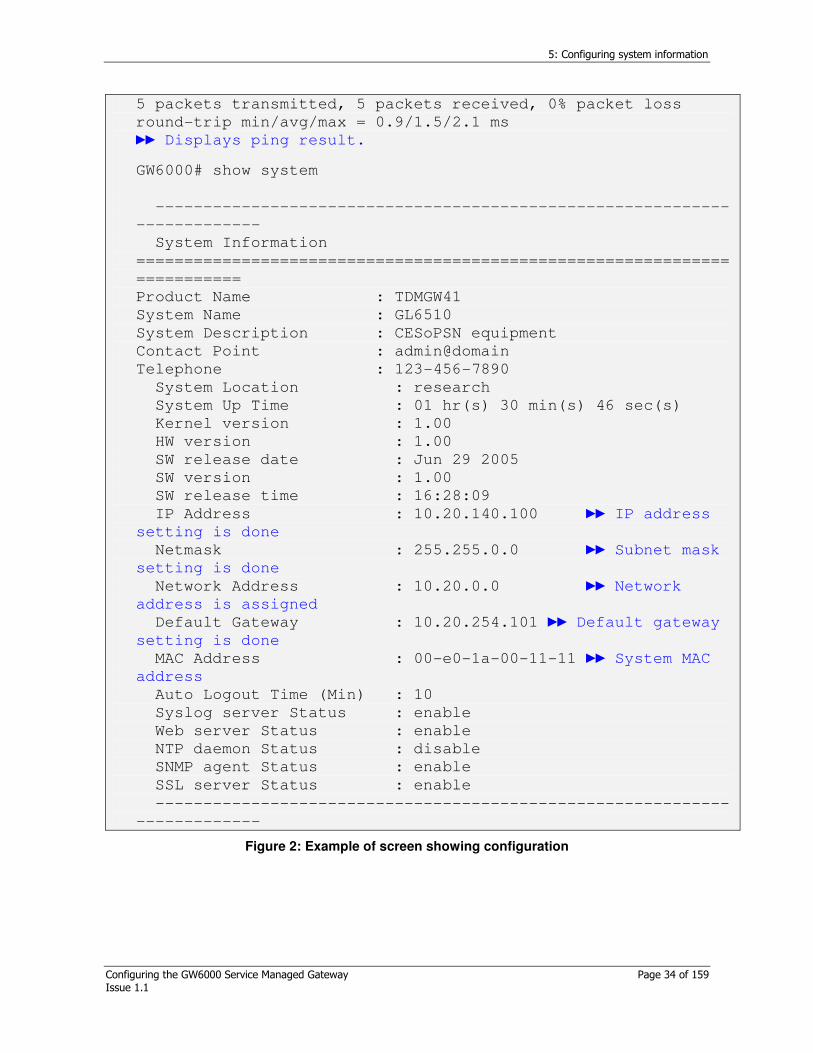
5 packets transmitted, 5 packets received, 0% packet loss
round-trip min/avg/max = 0.9/1.5/2.1 ms
Displays ping result.
GW6000# show system
------------------------------------------------------------
-------------
System Information
==============================================================
===========
Product Name : TDMGW41
System Name : GL6510
System Description : CESoPSN equipment
Contact Point : admin@domain
Telephone : 123-456-7890
System Location : research
System Up Time : 01 hr(s) 30 min(s) 46 sec(s)
Kernel version : 1.00
HW version : 1.00
SW release date : Jun 29 2005
SW version : 1.00
SW release time : 16:28:09
IP Address : 10.20.140.100 IP address
setting is done
Netmask : 255.255.0.0 Subnet mask
setting is done
Network Address : 10.20.0.0 Network
address is assigned
Default Gateway : 10.20.254.101 Default gateway
setting is done
MAC Address : 00-e0-1a-00-11-11 System MAC
address
Auto Logout Time (Min) : 10
Syslog server Status : enable
Web server Status : enable
NTP daemon Status : disable
SNMP agent Status : enable
SSL server Status : enable
------------------------------------------------------------
-------------
Figure 2: Example of screen showing configuration
5: Configuring system information
Configuring the GW6000 Service Managed Gateway Page 35 of 159 Issue 1.1
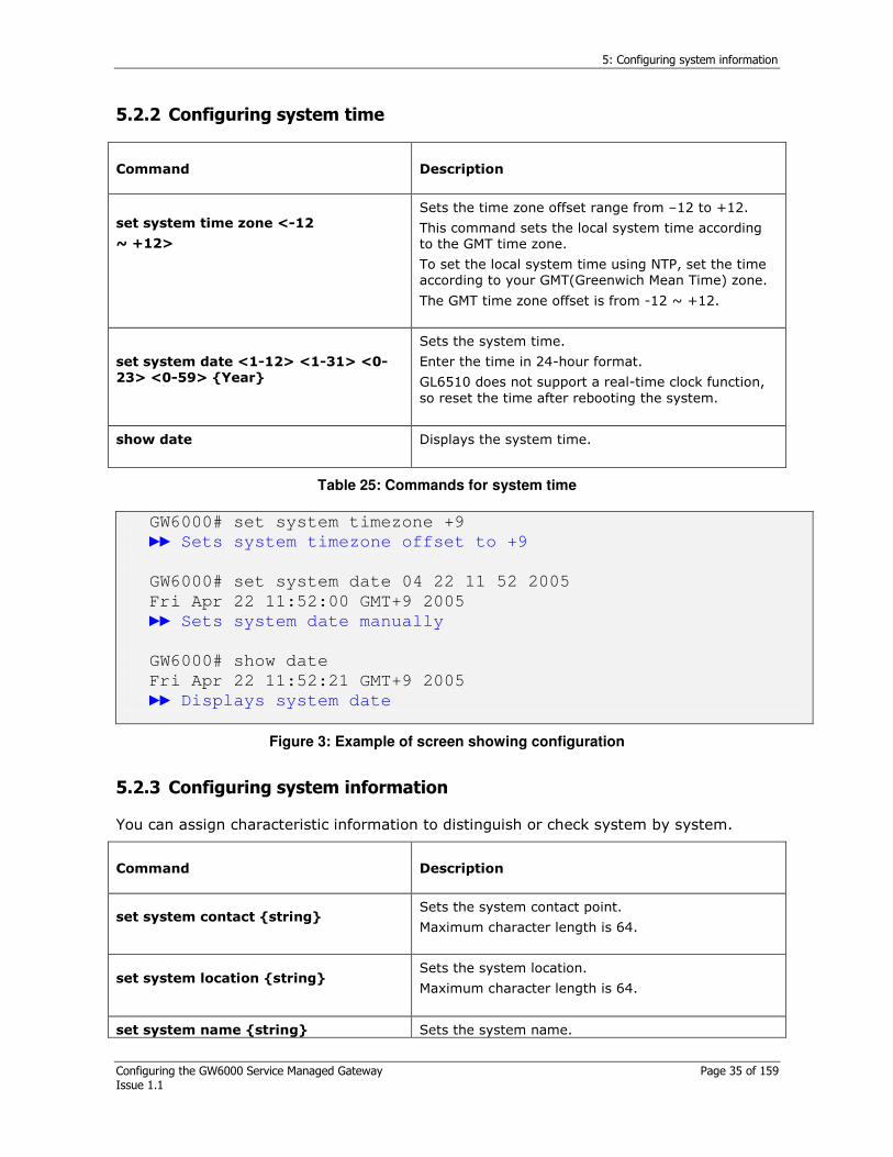
5.2.2 Configuring system time
Command Description
set system time zone <-12
~ +12>
Sets the time zone offset range from –12 to +12.
This command sets the local system time according to the GMT time zone.
To set the local system time using NTP, set the time according to your GMT(Greenwich Mean Time) zone.
The GMT time zone offset is from -12 ~ +12.
set system date <1-12> <1-31> <0-23> <0-59> Year
Sets the system time.
Enter the time in 24-hour format.
GL6510 does not support a real-time clock function, so reset the time after rebooting the system.
show date
Displays the system time.
Table 25: Commands for system time
GW6000# set system timezone +9
Sets system timezone offset to +9
GW6000# set system date 04 22 11 52 2005
Fri Apr 22 11:52:00 GMT+9 2005
Sets system date manually
GW6000# show date
Fri Apr 22 11:52:21 GMT+9 2005
Displays system date
Figure 3: Example of screen showing configuration
5.2.3 Configuring system information
You can assign characteristic information to distinguish or check system by system.
Command Description
set system contact string
Sets the system contact point.
Maximum character length is 64.
set system location string
Sets the system location.
Maximum character length is 64.
set system name string Sets the system name.
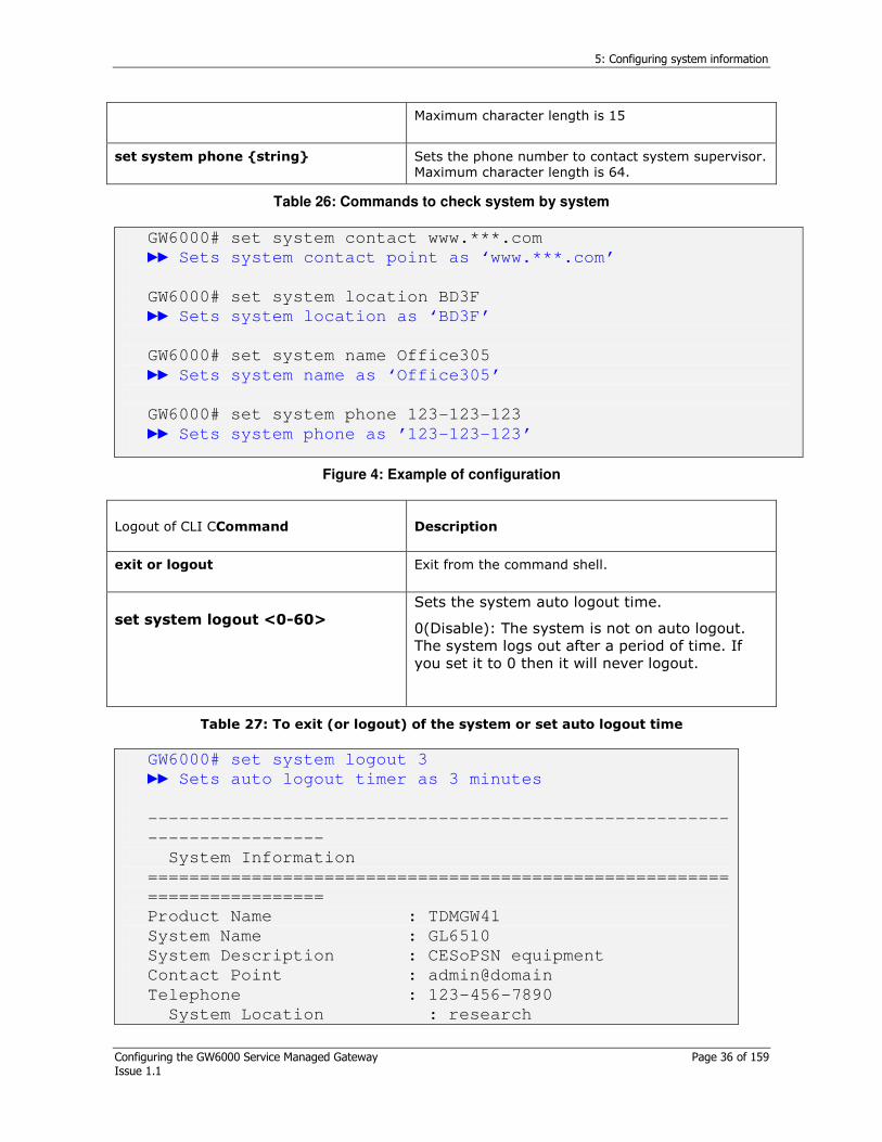
5: Configuring system information
Configuring the GW6000 Service Managed Gateway Page 36 of 159 Issue 1.1
Maximum character length is 15
set system phone string
Sets the phone number to contact system supervisor. Maximum character length is 64.
Table 26: Commands to check system by system
GW6000# set system contact www.***.com
Sets system contact point as ‘www.***.com’
GW6000# set system location BD3F
Sets system location as ‘BD3F’
GW6000# set system name Office305
Sets system name as ‘Office305’
GW6000# set system phone 123-123-123
Sets system phone as ’123-123-123’
Figure 4: Example of configuration
Logout of CLI CCommand Description
exit or logout
Exit from the command shell.
set system logout <0-60>
Sets the system auto logout time.
0(Disable): The system is not on auto logout. The system logs out after a period of time. If you set it to 0 then it will never logout.
Table 27: To exit (or logout) of the system or set auto logout time
GW6000# set system logout 3
Sets auto logout timer as 3 minutes
--------------------------------------------------------
-----------------
System Information
========================================================
=================
Product Name : TDMGW41
System Name : GL6510
System Description : CESoPSN equipment
Contact Point : admin@domain
Telephone : 123-456-7890
System Location : research

5: Configuring system information
Configuring the GW6000 Service Managed Gateway Page 37 of 159 Issue 1.1
System Up Time : 01 hr(s) 30 min(s) 46
sec(s)
Kernel version : 1.00
HW version : 1.00
SW release date : Jun 29 2005
SW version : 1.00
SW release time : 16:28:09
IP Address : 10.20.140.100
Netmask : 255.255.0.0
Network Address : 10.20.0.0
Default Gateway : 10.20.254.101
MAC Address : 00-e0-1a-00-11-11
Auto Logout Time (Min) : 3 Auto logout
time configured as 3 minutes
Syslog server Status : enable
Web server Status : enable
NTP daemon Status : disable
SNMP agent Status : enable
SSL server Status : enable
------------------------------------------------------
-------------------
Figure 5: Example of system logout configuration
If you set the logout time you will have to login again, manually.
5.2.4 System daemon process
System processes can be enabled and disabled using the commands below.
To enable the processing system feature, you can control the system daemon status
Command Description
set system http (disable|enable)
Disables or enables the HTTP daemon processing status.
set system ssl (disable|enable)
Disables or enables the SSL (Secure Sockets Layer) daemon processing status.
set log (disable|enable)
Disables or enables the syslog agent daemon processing status.
set snmp (disable|enable)
Disables or enables the SNMP agent daemon processing status.
set ntp (disable|enable)
Disables or enables the NTP client daemon processing status.
Table 28: Commands

5: Configuring system information
Configuring the GW6000 Service Managed Gateway Page 38 of 159 Issue 1.1
GW6000# set system http enable
Sets HTTP processing daemon to enable
GW6000# set system ssl enable
Sets SSL processing daemon to enable
GW6000# set log enable
Sets HTTP processing daemon to enable
GW6000# set snmp enable
Sets SNMP processing daemon to enable
GW6000# set ntp enable
Sets HTTP processing daemon to enable
GW6000# show system
---------------------------------------------------------
----------------
System Information
===========================================================
==============
Product Name : TDMGW41
System Name : GL6510
…
Auto Logout Time (Min) : 3
Syslog server Status : enable Syslog status is
enabled
Web server Status : enable HTTP daemon status
is enabled
NTP daemon Status : enable NTP daemon status
is enabled
SNMP agent Status : enable SNMP daemon status
is enabled
SSL server Status : enable SSL daemon status
is enabled -------------------------------------------------------------------------
Figure 6: Example of configuration
5.2.5 System maintenance
Command Description
set system initialize
Initializes the current settings to the default settings. The system is restored to default settings once the system is rebooted.
5: Configuring system information
Configuring the GW6000 Service Managed Gateway Page 39 of 159 Issue 1.1
* After initializing the system, induce ‘reboot’.
reboot
Reboots the system.
save
Saves the configuration.
ping
Sends an ICMP request to check the network connection.
update
Updates image from its internal RAM to novitiate ROM.
Table 29: Commands and their description
Although the system is initialized, ces-psn, system IP address, and gateway are kept at the previous value.
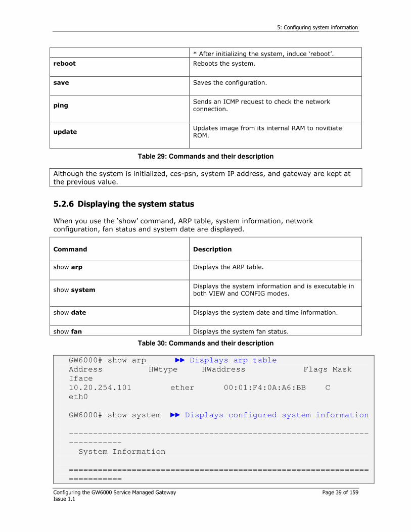
5.2.6 Displaying the system status
When you use the ‘show’ command, ARP table, system information, network configuration, fan status and system date are displayed.
Command Description
show arp
Displays the ARP table.
show system
Displays the system information and is executable in both VIEW and CONFIG modes.
show date
Displays the system date and time information.
show fan Displays the system fan status.
Table 30: Commands and their description
GW6000# show arp Displays arp table
Address HWtype HWaddress Flags Mask
Iface
10.20.254.101 ether 00:01:F4:0A:A6:BB C
eth0
GW6000# show system Displays configured system information
--------------------------------------------------------------
-----------
System Information
==============================================================
===========

5: Configuring system information
Configuring the GW6000 Service Managed Gateway Page 40 of 159 Issue 1.1
Product Name : TDMGW41
System Name : TDMGW
System Description : CESoPSN equipment
Contact Point : admin@domain
Telephone : 123-456-7890
System Location : research
System Up Time : 00 hr(s) 05 min(s) 57 sec(s)
Kernel version : 1.00
HW version : 1.00
SW release date : Apr 20 2005
SW version : 1.00
SW release time : 16:28:09
IP Address : 10.20.140.100
Netmask : 255.255.0.0
Network Address : 10.20.0.0
Default Gateway : 10.20.254.101
MAC Address : 00-e0-1a-00-11-11
Auto Logout Time (Min) : 10
Syslog server Status : enable
Web server Status : enable
NTP daemon Status : enable
SNMP agent Status : enable
SSL server Status : enable
--------------------------------------------------------------
-----------
GW6000# show date Displays system date
Mon Apr 25 19:19:03 GMT+9 2005
GW6000# show fan Displays fan status
FAN Status
---------------------------------------------------
FAN A Normal
FAN B Normal
---------------------------------------------------
Figure 7: Example of a screen showing configuration
5.3 System image upgrade
5.3.1.1 Upgrade via FTP
GL6510 provides a software change function while operating after booting the system normally. After setting the system IP and connecting the system, (Figure 9) you can download the software from the FTP server and save it to the flash memory.

5: Configuring system information
Configuring the GW6000 Service Managed Gateway Page 41 of 159 Issue 1.1
FTP Server
Network
Telenet host
Figure 8: Software upgrade via CLI or Telnet
Command Description
ftp A.B.C.D
Downloads the file from the FTP server to the system. Usually an FTP server connection is used for downloading new software image or profile.
After completing the download, the software is automatically saved to the flash memory.
update (kernel| ramdisk|ppcboot) Updates the system from dram to flash memory.
Reboot the system after updating
Table 31: Commands
GW6000# set system ip 192.168.1.20/24
Sets system IP address as 192.168.1.20
GW6000# ftp 192.168.1.1
Connects to ftp server
Connected to 192.168.1.1.
220 3Com 3CDaemon FTP Server Version 2.0
Name (192.168.1.1:root): user1
Enters user account
331 User name ok, need password
Password:******
Enters designated password
230 User logged in
Remote system type is UNIX.
Using binary mode to transfer files.
ftp> hash
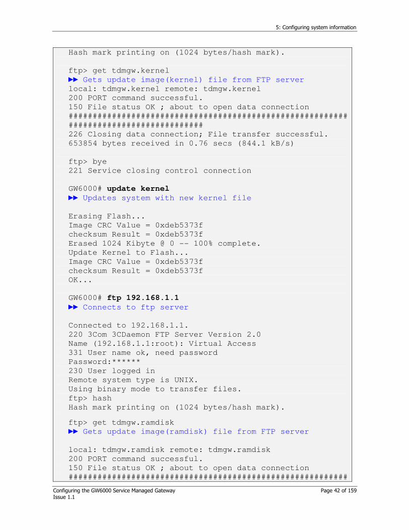
5: Configuring system information
Configuring the GW6000 Service Managed Gateway Page 42 of 159 Issue 1.1
Hash mark printing on (1024 bytes/hash mark).
ftp> get tdmgw.kernel
Gets update image(kernel) file from FTP server
local: tdmgw.kernel remote: tdmgw.kernel
200 PORT command successful.
150 File status OK ; about to open data connection
##########################################################
############################
226 Closing data connection; File transfer successful.
653854 bytes received in 0.76 secs (844.1 kB/s)
ftp> bye
221 Service closing control connection
GW6000# update kernel
Updates system with new kernel file
Erasing Flash...
Image CRC Value = 0xdeb5373f
checksum Result = 0xdeb5373f
Erased 1024 Kibyte @ 0 -- 100% complete.
Update Kernel to Flash...
Image CRC Value = 0xdeb5373f
checksum Result = 0xdeb5373f
OK...
GW6000# ftp 192.168.1.1
Connects to ftp server
Connected to 192.168.1.1.
220 3Com 3CDaemon FTP Server Version 2.0
Name (192.168.1.1:root): Virtual Access
331 User name ok, need password
Password:******
230 User logged in
Remote system type is UNIX.
Using binary mode to transfer files.
ftp> hash
Hash mark printing on (1024 bytes/hash mark).
ftp> get tdmgw.ramdisk
Gets update image(ramdisk) file from FTP server
local: tdmgw.ramdisk remote: tdmgw.ramdisk
200 PORT command successful.
150 File status OK ; about to open data connection
##########################################################

5: Configuring system information
Configuring the GW6000 Service Managed Gateway Page 43 of 159 Issue 1.1
##########################################################
##########################################################
##########################################################
##########################################################
##########################################################
##########################################################
##########################################################
##########################################################
##########################################################
##########################################################
##########################################################
##########
226 Closing data connection; File transfer successful.
5766729 bytes received in 6.40 secs (879.4 kB/s)
ftp> bye
Disconnect to FTP server
221 Service closing control connection
GW6000# update ramdisk
Updates system with new ramdisk file.
Erasing Flash...
Image CRC Value = 0x4300aee2
checksum Result = 0x4300aee2
Erased 7168 Kibyte @ 0 -- 100% complete.
Update Ramdisk to Flash...
Image CRC Value = 0x4300aee2
checksum Result = 0x4300aee2
OK...
GW6000# reboot
Figure 9: Example of configuration

6: Configuring the Ethernet port
Configuring the GW6000 Service Managed Gateway Page 44 of 159 Issue 1.1
6 Configuring the Ethernet port
GL6510’s 10/100Base-Tx Ethernet ports provide an L1 physical feature like Auto Negotiation, Auto-MDIX management feature like IP, MAC address. This section describes the port related configuration settings.
The GL6510 has two uplink ports mounted for processing TDM packet encapsulated RTP-PW or MEF-PW and four LAN ports used for packet network users.
The GL6510-P4, has two LAN ports mounted for processing only TDM packet encapsulated RTP-PW or MEF-PW.
6.1 Commands for LAN configuration
Command Description
set eth port auto-nego
enable (<Portlist>| all)
Sets the auto negotiation mode as enable or disable.
If the remote port is set to “Auto negotiation”, the port speed and duplex are recognised automatically.
Correct use of commands:
1. set eth port auto-nego enable 1-up2 (X)
2. set eth port auto-nego enable 1-4, up1-up2 (O)
set eth port admin-status
(enable|disable)
(<Portlist>|all)
Sets the administration status of a port.
The default value is “enable”. If this command is set to “disable”, packet transmission is blocked via this port.
set eth port speed
(10hd|10fd|100hd|100fd)
(<Portlist>|all)
Sets the port to “force” speed and duplex mode.
Force mode sets the port speed regardless of the status of the corresponding port.
10hd: Establishes its link to forced 10Mbps half duplex mode.
10fd: Establishes its link to forced 10Mbps full duplex mode.
100hd: Establishes its link to forced 100Mbps half duplex mode.
100fd: Establishes its link to forced 100Mbps full duplex mode.
Correct use of commands:
1. set eth port speed 100fd 1-up2 (X)
2. set eth port speed 100fd 1-4, up1, up2 (O)
set eth port flow-control
(on|off) (<Portlist >|all)
Sets the IP address of the LAN port 1
set eth port statistic
clear(<Portlist>|all)
Clears the accumulated port counter to ‘0’.
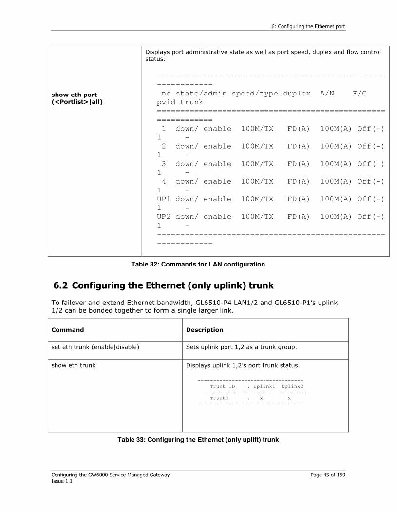
6: Configuring the Ethernet port
Configuring the GW6000 Service Managed Gateway Page 45 of 159 Issue 1.1
show eth port
(<Portlist>|all)
Displays port administrative state as well as port speed, duplex and flow control status.
-------------------------------------------------
------------
no state/admin speed/type duplex A/N F/C
pvid trunk
=================================================
============
1 down/ enable 100M/TX FD(A) 100M(A) Off(-)
1 -
2 down/ enable 100M/TX FD(A) 100M(A) Off(-)
1 -
3 down/ enable 100M/TX FD(A) 100M(A) Off(-)
1 -
4 down/ enable 100M/TX FD(A) 100M(A) Off(-)
1 -
UP1 down/ enable 100M/TX FD(A) 100M(A) Off(-)
1 -
UP2 down/ enable 100M/TX FD(A) 100M(A) Off(-)
1 -
-------------------------------------------------
------------
Table 32: Commands for LAN configuration
6.2 Configuring the Ethernet (only uplink) trunk
To failover and extend Ethernet bandwidth, GL6510-P4 LAN1/2 and GL6510-P1’s uplink 1/2 can be bonded together to form a single larger link.
Command Description
set eth trunk (enable|disable)
Sets uplink port 1,2 as a trunk group.
show eth trunk
Displays uplink 1,2’s port trunk status.
----------------------------------
Trunk ID : Uplink1 Uplink2
==================================
Trunk0 : X X
----------------------------------
Table 33: Configuring the Ethernet (only uplift) trunk

6: Configuring the Ethernet port
Configuring the GW6000 Service Managed Gateway Page 46 of 159 Issue 1.1
To aggregate the trunk group successfully, first check that Ethernet ports are fixed as either auto negotiation or full duplex mode.
6.3 Displaying the LAN port statistic counter
GL6510 counts and displays transmitted and received packets per each port.
Command Description
set eth port statistic clear
(<Portlist>|mgmt|all)
Clear accumulated packet counter.
show eth port statistic
(<Portlist>|mgmt|all)
Displays Ethernet LAN and uplink ports frame counters.
Receive Total
Rx Byte Displays the number of received bytes in good and bad packets.
Rx Packet Displays the number of received good and bad frame.
Rx Good Byte Displays the number of received bytes in good packets.
Rx Good Packet Displays the number of received good frame.
Rx Fc Packet Displays the number of received pause frame.
Rx Multicast Packet
Displays the number of received multicast frame.
Rx Broadcast Packet
Displays the number of received broadcast frame.
Rx Alignment Error
Displays the number of received alignment errors.
Rx CRC Error Displays the number of received CRC errors.
Rx Oversize Error Displays the number of received frames longer than max frame length bytes with valid CRC.
Rx Runt Error Displays the number of received frames shorter than 64 bytes with valid CRC.
Rx Dropped Error Displays the number of times a frame is dropped, because of lack of available resources.
Rx Jabber Error Displays the number of received frames longer than max frame length bytes with invalid CRC.
Rx 64b Packet Displays the number of received 64bytes frames in good and bad packets.
Rx 65-127b Packet
Displays the number of received 65~127bytes received frames in

6: Configuring the Ethernet port
Configuring the GW6000 Service Managed Gateway Page 47 of 159 Issue 1.1
good and bad packets.
Rx 128-255b Packet
Displays the number of received 128~255bytes received frames in good and bad packets.
Rx 256-511b Packet
Displays the number of received 256~511bytes received frames in good and bad packets.
Rx 512-1023b Packet
Displays the number of received 512~1023bytes received frames in good and bad packets.
Rx 1024-1518b Packet
Displays the number of received 1024~1518 bytes received frames in good and bad packets.
Rx Coll Displays the number of received collision.
Rx Late Coll Displays the number of received collision events that occurred late.
Rx Fragmentation Displays the number of received frames shorter than 64 bytes with invalid CRC.
Rx Short Event Counts and displays the number of received frames less than 10 bytes.
Transmit Total
Tx Byte Counts the number of transmitted bytes in good and bad packets.
Tx Unicast Packet
Counts the number of transmitted unicast packets.
Tx Packet Error Counts the number of transmitted failure packets.
Tx Fc Packet Counts the number of transmitted pause packets.
7: Configuring VLAN
Configuring the GW6000 Service Managed Gateway Page 48 of 159 Issue 1.1
7 Configuring VLAN
If the broadcasting packet enters a LAN, all nodes on the LAN receive the broadcasting packet. In this case, the nodes that do not require this information receive the broadcasting packet, and then the traffic is increased. To make up for this problem, the GL6510 provides a Virtual LAN (VLAN) based on IEEE802.1Q for Ethernet ports. The advantages are that unnecessary traffic is decreased and security is improved because packets cannot be exchanged among different VLANs.
7.1 Commands for IEEE802.1Q Tagged VLAN
GL6510 supports the 802.1Q tagged based VLAN. Tagging is the process of adding 4 bytes tag containing the VID (VLAN ID) to an Ethernet frame. The tagged frame size may be up to 1522 bytes. By default all GL6510’s Ethernet ports are untagged members of VLAN 1. The default VLAN members may be added or deleted but VLAN ID 1 can’t be removed.
Command Description
set eth vlan create Name <VLAN
ID>
Creates a VLAN. This sets the VID, the VLAN name. When creating a VLAN.
A VLAN name stands in for a VLAN.
The VID is used for compatibility between LAN devices when using a VLAN over several LAN devices. It consists of less than 10 characters, and several special characters may be used (~`!@#$%^&*()-_+=\|/’”[]), though spaces may not be used.
A letter must be used for the first letter of a VLAN name. A VLAN name is recognised locally inside a device but the VID is recognised by a device directly connected via a trunk link
A VID can be from 2~4094. The VID 1 is set as the ‘default’ and 0 and 4095 is reserved ID.
set eth vlan delete (<VLAN
ID>|all)
Deletes all VLAN Groups except the default VLAN 1
set eth vlan add-port <VLAN ID>
<Portlist>
Adds member ports to a VLAN. If a port is added, the PVID of the added port is set as a VID of the VLAN it belongs to.
set eth vlan del-port <VLAN ID>
<Portlist>
Adds member ports to a VLAN. If a port is added, the PVID of the added port is set as a VID of the VLAN it belongs to.
set eth vlan pvid (<VLAN ID>|cpu)
<Portlist>
Sets the PVID for each port. If an untagged packet enters the port, it adds a tag to the PVID and sends it. By default, the PVID of all ports is set to 1.
7: Configuring VLAN
Configuring the GW6000 Service Managed Gateway Page 49 of 159 Issue 1.1
show eth vlan
Displays the VLAN information. ‘U’ on the IEEE 802.1Q VLAN mode indicates an untagged member port and ‘T’ indicates a tagged member port.
Table 34: Commands for IEEE802.1Q tagged VLAN
7.1.1 Tagged/untagged mode
If a port belongs to a specific VLAN as untagged, then the port sends the frame without tagging. But if the port belongs to a VLAN with tagged mode, it sends the frame with VLAN tagging (The tag value should be equal to VLAN ID).
7.1.2 The advantage of a IEEE 802.1Q tagged VLAN
By adding port(s) as tagged to all VLAN groups and assigning PVID as 1, then this tagged port is able to carry forward every VLAN ID to remote side’s destination ports located in the same VLAN group. So if several devices with multiple VLANs are connected then add the same ports as “tagged” to each VLAN so that the VLAN IDs can be forwarded between the devices.
The tagged uplink that connects devices is usually called to the ‘1Q-tagged’ or ‘1Q-trunk’ port.
7.1.3 PVID (Port VLAN ID)
The PVID is the value that is set for each port and the default value is 1. A ‘default’ VLAN is automatically set when the device is booted, where all ports are in untagged mode. When a VLAN is created, the PVID of the VLAN member ports are automatically set to the created VLAN ID. In cases where a port is added to a VLAN, it is set as an added VLAN ID. If a VLAN is removed or the port is removed from a VLAN and the PVID is the same as the VLAN ID, it is set to 1.

7: Configuring VLAN
Configuring the GW6000 Service Managed Gateway Page 50 of 159 Issue 1.1
100
100
200
200
A
A <->B, X<->Y is o.k A<->Y, B<->X is fail
GW6510 A
GW6510 B
X
Y
B
Figure 10: How to create a VLAN, adding/deleting a port, and removing a VLAN
Step 1: Creating VLAN
GW6000 # set eth vlan create 100 100
GW6000 # set eth vlan create 200 200
Step 2: Add untagged port to new VLAN
GW6000# set eth vlan add-port 100 1-2 untagged
GW6000# set eth vlan add-port 200 3-4 untagged
Step 3: Add tagged port to VLAN
GW6000# set eth vlan add-port 1 up1 tagged
GW6000# set eth vlan add-port 1 up2 tagged
GW6000# set eth vlan add-port 100 up1 tagged
GW6000# set eth vlan add-port 100 up2 tagged
GW6000# set eth vlan add-port 200 up1 tagged
GW6000# set eth vlan add-port 200 up2 tagged
Step 4: Setting PVID
GW6000# set eth vlan pvid 100 1,2
GW6000# set eth vlan pvid 200 3,4
GW6000# set eth vlan pvid 1 up1
GW6000# set eth vlan pvid 1 up2
Step 5: Displaying VLAN configuration
GW6000# show eth vlan
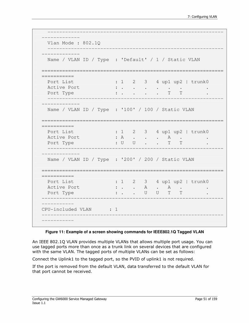
7: Configuring VLAN
Configuring the GW6000 Service Managed Gateway Page 51 of 159 Issue 1.1
------------------------------------------------------------
-------------
Vlan Mode : 802.1Q
------------------------------------------------------------
-------------
Name / VLAN ID / Type : 'Default' / 1 / Static VLAN
==============================================================
===========
Port List : 1 2 3 4 up1 up2 | trunk0
Active Port : . . . . . . .
Port Type : . . . . T T .
------------------------------------------------------------
-------------
Name / VLAN ID / Type : '100' / 100 / Static VLAN
==============================================================
===========
Port List : 1 2 3 4 up1 up2 | trunk0
Active Port : A . . . A . .
Port Type : U U . . T T .
------------------------------------------------------------
-------------
Name / VLAN ID / Type : '200' / 200 / Static VLAN
==============================================================
===========
Port List : 1 2 3 4 up1 up2 | trunk0
Active Port : . . A . A . .
Port Type : . . U U T T .
--------------------------------------------------------------
-----------
CPU-included VLAN : 1
--------------------------------------------------------------
-----------
Figure 11: Example of a screen showing commands for IEEE802.1Q Tagged VLAN
An IEEE 802.1Q VLAN provides multiple VLANs that allows multiple port usage. You can use tagged ports more than once as a trunk link on several devices that are configured with the same VLAN. The tagged ports of multiple VLANs can be set as follows:
Connect the Uplink1 to the tagged port, so the PVID of uplink1 is not required.
If the port is removed from the default VLAN, data transferred to the default VLAN for that port cannot be received.

7: Configuring VLAN
Configuring the GW6000 Service Managed Gateway Page 52 of 159 Issue 1.1
7.2 CPU protection by VLAN
GL6510 protects its CPU performance and access by adding the CPU to a specific VLAN.
Command Description
set eth vlan add-cpu <VLAN ID>
Adds the CPU port to specific VLAN group.
set eth vlan del-cpu <VLAN ID>
Deletes the CPU port to specific VLAN group.
set eth vlan pvid cpu <VLAN ID>
Sets the PVID for each port. If an untagged packet enters the port, it adds a tag to the PVID and sends it. By default, the PVID of all ports is set to 1.
Table 35: Commands for adding the CPU to a specific VLAN
100
300
GW6510 A:
10.20.1.100/16
PC_A: 10.20.1.1/16
PC_B: 10.20.1.2/16
GW6510 B:
10.20.1.101/16
A
B
Figure 12: Configuration of CPU accessible VLAN
Configuration 1) PC_A can access GL6510 A and B’s CPU. But PC_B can’t access GL6510 A and B.
Step 1:
Finish the VLAN configurations like above referring to
Example 1.
Step 2: Delete VLAN 1 and add VLAN 100 to CPU
GL6510A side
GW6000 # set eth vlan del-cpu 1
GW6000 # set eth vlan add-cpu 100
GL6510B side
GW6000 # set eth vlan del-cpu 1
GW6000 # set eth vlan add-cpu 100
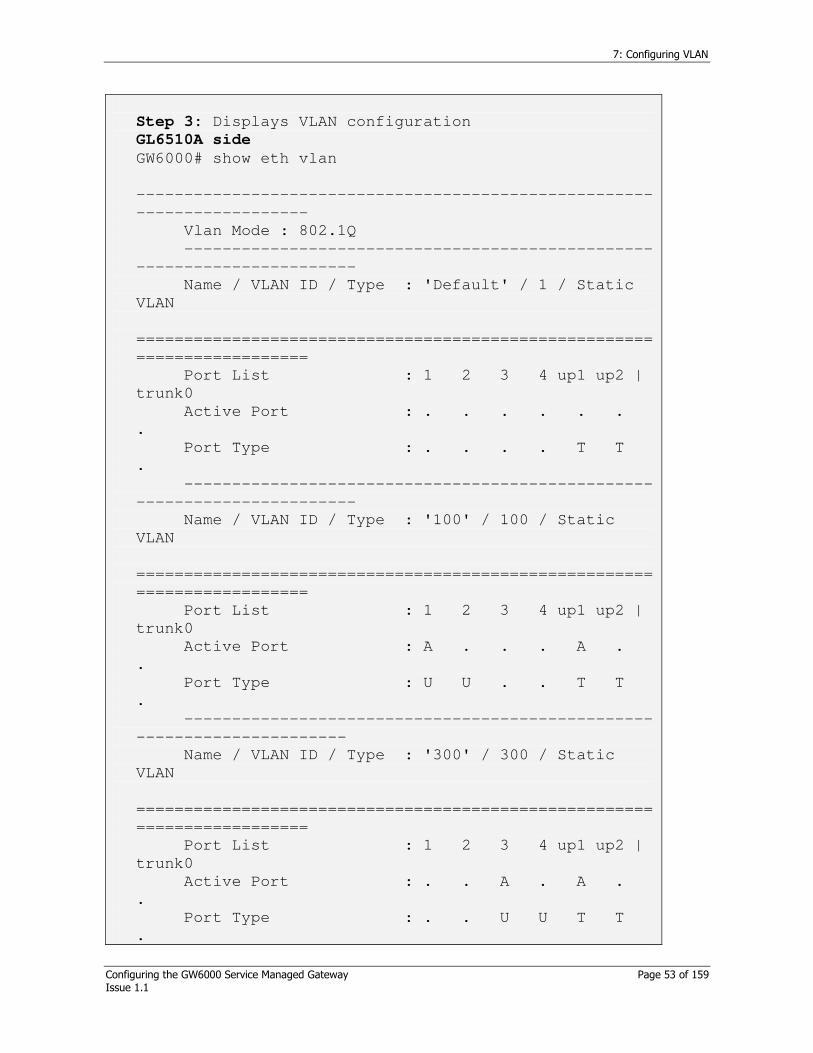
7: Configuring VLAN
Configuring the GW6000 Service Managed Gateway Page 53 of 159 Issue 1.1
Step 3: Displays VLAN configuration
GL6510A side
GW6000# show eth vlan
------------------------------------------------------
------------------
Vlan Mode : 802.1Q
-------------------------------------------------
-----------------------
Name / VLAN ID / Type : 'Default' / 1 / Static
VLAN
======================================================
==================
Port List : 1 2 3 4 up1 up2 |
trunk0
Active Port : . . . . . .
.
Port Type : . . . . T T
.
-------------------------------------------------
-----------------------
Name / VLAN ID / Type : '100' / 100 / Static
VLAN
======================================================
==================
Port List : 1 2 3 4 up1 up2 |
trunk0
Active Port : A . . . A .
.
Port Type : U U . . T T
.
-------------------------------------------------
----------------------
Name / VLAN ID / Type : '300' / 300 / Static
VLAN
======================================================
==================
Port List : 1 2 3 4 up1 up2 |
trunk0
Active Port : . . A . A .
.
Port Type : . . U U T T
.
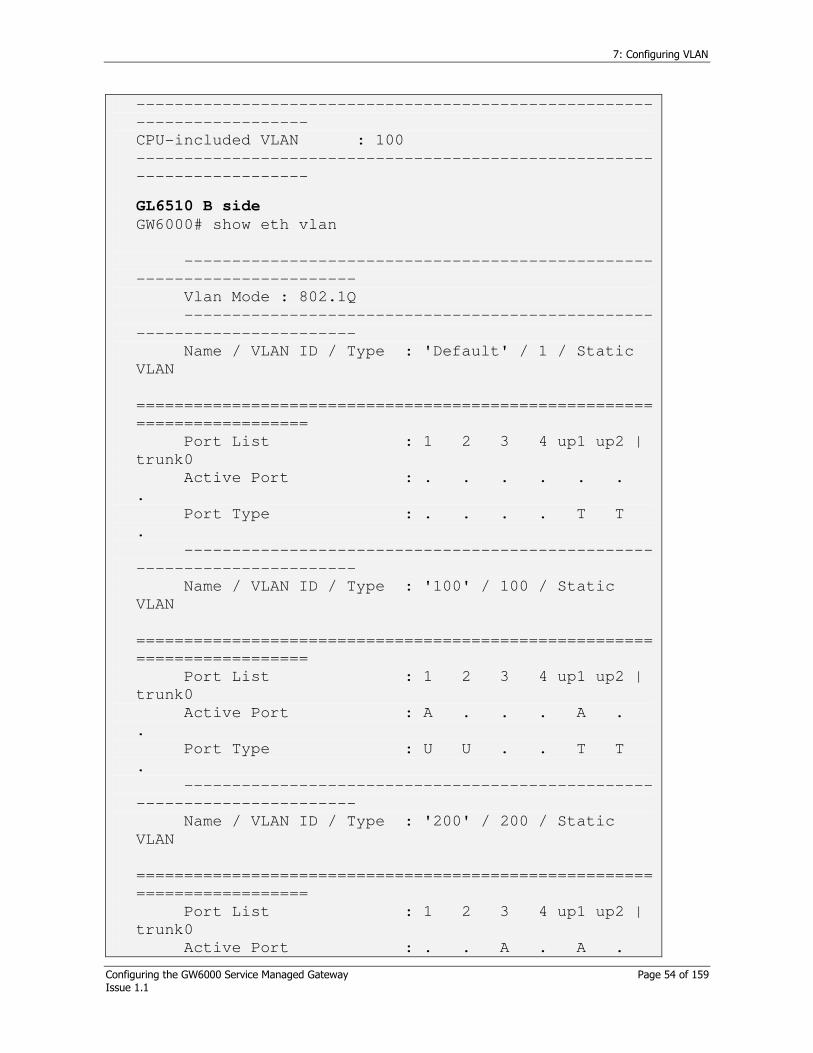
7: Configuring VLAN
Configuring the GW6000 Service Managed Gateway Page 54 of 159 Issue 1.1
------------------------------------------------------
------------------
CPU-included VLAN : 100
------------------------------------------------------
------------------
GL6510 B side
GW6000# show eth vlan
-------------------------------------------------
-----------------------
Vlan Mode : 802.1Q
-------------------------------------------------
-----------------------
Name / VLAN ID / Type : 'Default' / 1 / Static
VLAN
======================================================
==================
Port List : 1 2 3 4 up1 up2 |
trunk0
Active Port : . . . . . .
.
Port Type : . . . . T T
.
-------------------------------------------------
-----------------------
Name / VLAN ID / Type : '100' / 100 / Static
VLAN
======================================================
==================
Port List : 1 2 3 4 up1 up2 |
trunk0
Active Port : A . . . A .
.
Port Type : U U . . T T
.
-------------------------------------------------
-----------------------
Name / VLAN ID / Type : '200' / 200 / Static
VLAN
======================================================
==================
Port List : 1 2 3 4 up1 up2 |
trunk0
Active Port : . . A . A .
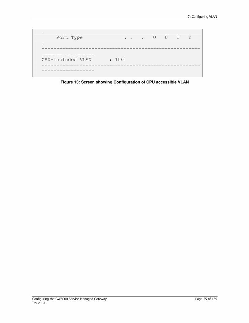
7: Configuring VLAN
Configuring the GW6000 Service Managed Gateway Page 55 of 159 Issue 1.1
.
Port Type : . . U U T T
.
------------------------------------------------------
------------------
CPU-included VLAN : 100
------------------------------------------------------
------------------
Figure 13: Screen showing Configuration of CPU accessible VLAN

8: Configuring spanning tree protocol
Configuring the GW6000 Service Managed Gateway Page 56 of 159 Issue 1.1
8 Configuring spanning tree protocol
8.1 Spanning tree introduction
If a LAN is composed of multiple separated areas via devices, there may be more than one physical path for communication between the different areas. An undesired loop can be caused by the basic switch characteristic that gets the MAC addresses of hosts belonging to the LAN and creates a network path. In this case, communication between hosts that want to communicate is abnormal and has a negative effect on the whole network. The protocol used to prevent the loop occuring, maintain one normal path on the LAN, and preserve one tree type topology by changing the path, if there is any error on the path, is called the Spanning Tree Protocol (STP).
The GL6510 allows STP based on 802.1D so network topology is preserved.
8.2 Commands for spanning tree configuration
Command Description
set eth stp (enable|disable)
Activates/deactivates STP.
“enable” is the default setting.
The 802.1D device is enabled.
show eth stp bridge
Displays the operating status of STP. It displays the statistics for each BPDU, the current status on the topology and various kinds of timers.
show eth stp port [<PortList>]
Displays the main parameters participating in the STP and the role of the port participating in the STP. This can be any of the following parameters: disable, blocking, listening, learning, forwarding.
set eth stp bridge forward-
delay <4-30>
Sets the Forward Delay Time of the 802.1D device. The time unit is in seconds, the spanning tree state is transferred by the time unit, and the Forward Delay Time of the Root Bridge is used as the Aging Time of all switches participating in the topology when the topology changes.
set eth stp bridge hello-time
<1-10>
Sets the Hello time of the 802.1D device. The time unit is in seconds, and transfers the BPDU of each switch by the time unit. With 802.1D, the Hello Timer is only activated on the root bridge. If the Config BPDU is sent with this standard, the lower bridge receives it, modifies the information, and resends the Config BPDU to a lower device.
set eth stp bridge max-age
<6-40>
Sets the maximum age time of the 802.1D device. The time unit is in seconds. The maximum age is the
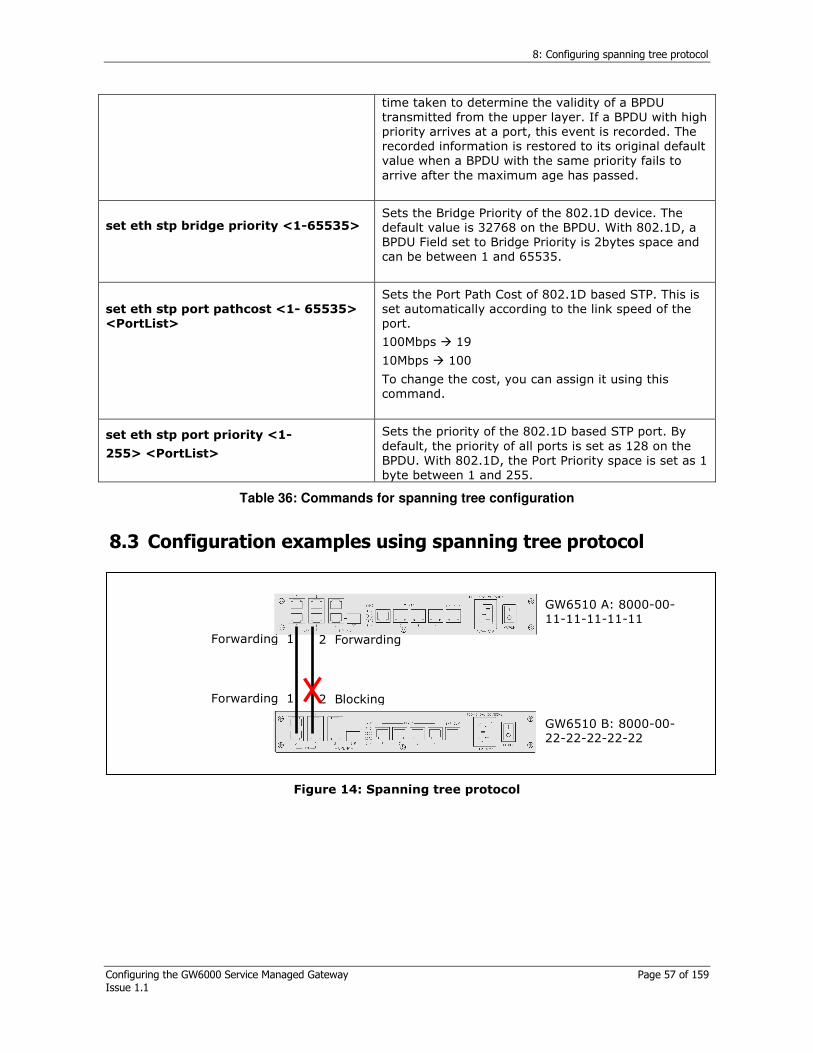
8: Configuring spanning tree protocol
Configuring the GW6000 Service Managed Gateway Page 57 of 159 Issue 1.1
time taken to determine the validity of a BPDU transmitted from the upper layer. If a BPDU with high priority arrives at a port, this event is recorded. The recorded information is restored to its original default value when a BPDU with the same priority fails to arrive after the maximum age has passed.
set eth stp bridge priority <1-65535>
Sets the Bridge Priority of the 802.1D device. The default value is 32768 on the BPDU. With 802.1D, a BPDU Field set to Bridge Priority is 2bytes space and can be between 1 and 65535.
set eth stp port pathcost <1- 65535>
<PortList>
Sets the Port Path Cost of 802.1D based STP. This is set automatically according to the link speed of the port.
100Mbps 19
10Mbps 100
To change the cost, you can assign it using this command.
set eth stp port priority <1-
255> <PortList>
Sets the priority of the 802.1D based STP port. By default, the priority of all ports is set as 128 on the BPDU. With 802.1D, the Port Priority space is set as 1 byte between 1 and 255.
Table 36: Commands for spanning tree configuration
8.3 Configuration examples using spanning tree protocol
2 Blocking Forwarding 1
GW6510 B: 8000-00-22-22-22-22-22
GW6510 A: 8000-00-11-11-11-11-11
Forwarding 1 2 Forwarding
Figure 14: Spanning tree protocol
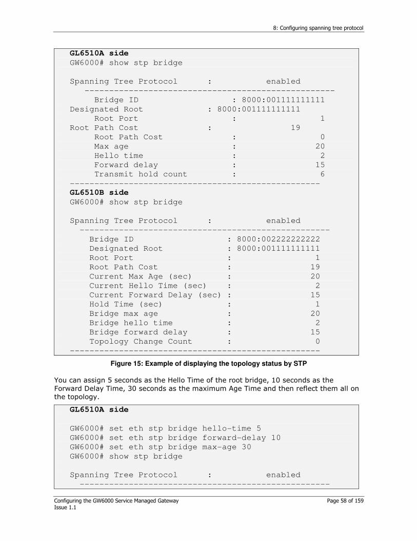
8: Configuring spanning tree protocol
Configuring the GW6000 Service Managed Gateway Page 58 of 159 Issue 1.1
GL6510A side
GW6000# show stp bridge
Spanning Tree Protocol : enabled
---------------------------------------------------
Bridge ID : 8000:001111111111
Designated Root : 8000:001111111111
Root Port : 1
Root Path Cost : 19
Root Path Cost : 0
Max age : 20
Hello time : 2
Forward delay : 15
Transmit hold count : 6
---------------------------------------------------
GL6510B side
GW6000# show stp bridge
Spanning Tree Protocol : enabled
---------------------------------------------------
Bridge ID : 8000:002222222222
Designated Root : 8000:001111111111
Root Port : 1
Root Path Cost : 19
Current Max Age (sec) : 20
Current Hello Time (sec) : 2
Current Forward Delay (sec) : 15
Hold Time (sec) : 1
Bridge max age : 20
Bridge hello time : 2
Bridge forward delay : 15
Topology Change Count : 0
---------------------------------------------------
Figure 15: Example of displaying the topology status by STP
You can assign 5 seconds as the Hello Time of the root bridge, 10 seconds as the Forward Delay Time, 30 seconds as the maximum Age Time and then reflect them all on the topology.
GL6510A side
GW6000# set eth stp bridge hello-time 5
GW6000# set eth stp bridge forward-delay 10
GW6000# set eth stp bridge max-age 30
GW6000# show stp bridge
Spanning Tree Protocol : enabled
---------------------------------------------------
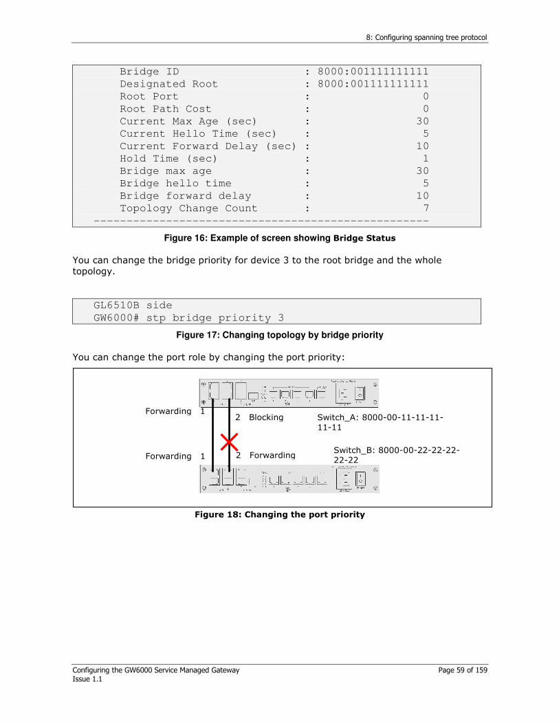
8: Configuring spanning tree protocol
Configuring the GW6000 Service Managed Gateway Page 59 of 159 Issue 1.1
Bridge ID : 8000:001111111111
Designated Root : 8000:001111111111
Root Port : 0
Root Path Cost : 0
Current Max Age (sec) : 30
Current Hello Time (sec) : 5
Current Forward Delay (sec) : 10
Hold Time (sec) : 1
Bridge max age : 30
Bridge hello time : 5
Bridge forward delay : 10
Topology Change Count : 7
---------------------------------------------------
Figure 16: Example of screen showing Bridge Status
You can change the bridge priority for device 3 to the root bridge and the whole topology.
GL6510B side
GW6000# stp bridge priority 3
Figure 17: Changing topology by bridge priority
You can change the port role by changing the port priority:
2 Forwarding Forwarding 1 Switch_B: 8000-00-22-22-22-22-22
Switch_A: 8000-00-11-11-11-11-11
Forwarding 1 2 Blocking
Figure 18: Changing the port priority
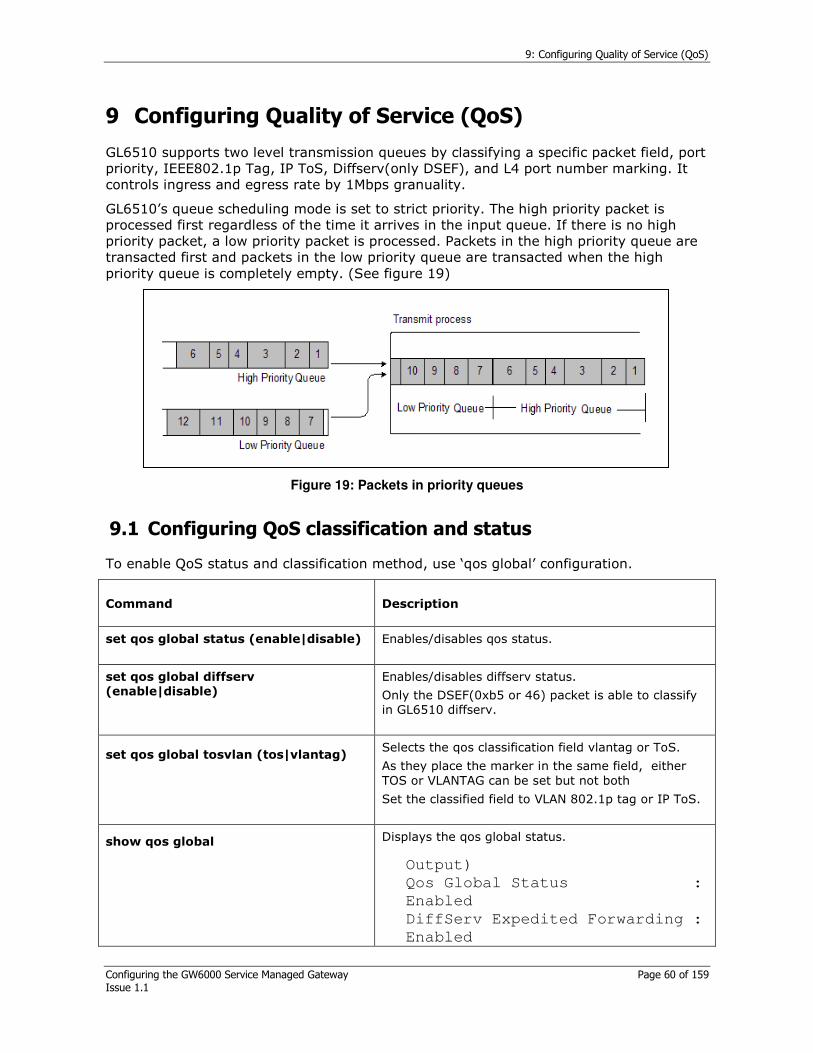
9: Configuring Quality of Service (QoS)
Configuring the GW6000 Service Managed Gateway Page 60 of 159 Issue 1.1
9 Configuring Quality of Service (QoS)
GL6510 supports two level transmission queues by classifying a specific packet field, port priority, IEEE802.1p Tag, IP ToS, Diffserv(only DSEF), and L4 port number marking. It controls ingress and egress rate by 1Mbps granuality.
GL6510’s queue scheduling mode is set to strict priority. The high priority packet is processed first regardless of the time it arrives in the input queue. If there is no high priority packet, a low priority packet is processed. Packets in the high priority queue are transacted first and packets in the low priority queue are transacted when the high priority queue is completely empty. (See figure 19)
Figure 19: Packets in priority queues
9.1 Configuring QoS classification and status
To enable QoS status and classification method, use ‘qos global’ configuration.
Command Description
set qos global status (enable|disable)
Enables/disables qos status.
set qos global diffserv
(enable|disable)
Enables/disables diffserv status.
Only the DSEF(0xb5 or 46) packet is able to classify in GL6510 diffserv.
set qos global tosvlan (tos|vlantag)
Selects the qos classification field vlantag or ToS.
As they place the marker in the same field, either TOS or VLANTAG can be set but not both
Set the classified field to VLAN 802.1p tag or IP ToS.
show qos global
Displays the qos global status.
Output)
Qos Global Status :
Enabled
DiffServ Expedited Forwarding :
Enabled

9: Configuring Quality of Service (QoS)
Configuring the GW6000 Service Managed Gateway Page 61 of 159 Issue 1.1
TosVlan mode :
Use VLAN Tag in 802.1Q header
Table 20: Commands and descriptions of QoS classification and status
9.2 Configuring classifying and scheduling
To configure classification fields and their transmission priority, use the following commands.
Command Description
set qos port-priority status <Portlist>
(enable|disable)
Enables/disables port priority.
set qos port-priority <Portlist> tx-
priority (high|low)
Sets port priority transmission queue level high or low.
The port that has its priority set to high will transmit frames before the one that has its priority set to low.
show qos port-priority
Displays configuration of port priority.
Table 21: Commands to configure classifying and scheduling
Command Description
set qos vlan <0-7> tx-priority
(hith|low)
Sets the IEEE802.1p VLAN tag field queue level to high or low.
show qos vlan
Displays configuration of port priority.
Table 22: VLAN Quality of Service
Command Description
set qos tos <0-7> tx-priority (hith|low)
Set\ the IP tos field queue level to high or low.
GL6510 uses bits from 2 to 4 as tos field.
show qos tos
Displays configuration of tos transmission priority.
Table 23: VLAN Type of Service
Command Description

9: Configuring Quality of Service (QoS)
Configuring the GW6000 Service Managed Gateway Page 62 of 159 Issue 1.1
set qos logicalport user-def <0-7> port-number <1-65535>
Sets the user-defined logical port number up to 8 indexes.
set qos logicalport (user-def|well-known) <0-7> tx-priority (hith|low)
Sets the transmission priority to high or low.
set qos logicalport (user-def|well-known) <0-7> port-status (enable|disable)
Enables/disables each logical (L4) port number’s qos status.
set qos logicalport rangeport lowport <1-65535>
Sets the low port number.
set qos logicalport rangeport highport <1-65535>
Sets the high port number.
set qos logicalport rangeport tx-priority (hith|low)
Enables/disables each logical (L4) port number’s qos status.
Figure 24: Port priority filter commands
GL6510’s QoS operation depends on internal mechanism. If L4 port, 21 should be classified and guaranteed its transmission, Port priority, Diffserv should be disabled at first.
QoS priority classification rule:
1. By user configuration, the classification field should be configured as ToS or VLAN, as they place the marker in the same field. Either TOS or
Port priority?
Diffserv (DSEF)?
IP Frame?
Use port priority
Yes
No
No
Use Logical priority
Use DSEF priority Yes
No
Yes Logical Port? Yes
No
Use VLAN tag or ToS priority VLAN tag is fixed by?
Use VLAN priority Yes
No
Use default priority
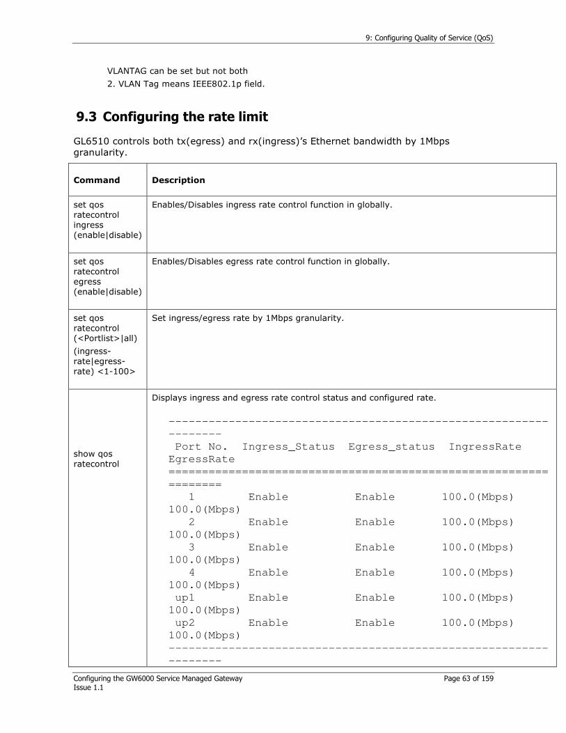
9: Configuring Quality of Service (QoS)
Configuring the GW6000 Service Managed Gateway Page 63 of 159 Issue 1.1
VLANTAG can be set but not both
2. VLAN Tag means IEEE802.1p field.
9.3 Configuring the rate limit
GL6510 controls both tx(egress) and rx(ingress)’s Ethernet bandwidth by 1Mbps granularity.
Command Description
set qos ratecontrol ingress (enable|disable)
Enables/Disables ingress rate control function in globally.
set qos ratecontrol egress (enable|disable)
Enables/Disables egress rate control function in globally.
set qos ratecontrol (<Portlist>|all)
(ingress-rate|egress-rate) <1-100>
Set ingress/egress rate by 1Mbps granularity.
show qos ratecontrol
Displays ingress and egress rate control status and configured rate.
---------------------------------------------------------
--------
Port No. Ingress_Status Egress_status IngressRate
EgressRate
=========================================================
========
1 Enable Enable 100.0(Mbps)
100.0(Mbps)
2 Enable Enable 100.0(Mbps)
100.0(Mbps)
3 Enable Enable 100.0(Mbps)
100.0(Mbps)
4 Enable Enable 100.0(Mbps)
100.0(Mbps)
up1 Enable Enable 100.0(Mbps)
100.0(Mbps)
up2 Enable Enable 100.0(Mbps)
100.0(Mbps)
---------------------------------------------------------
--------
9: Configuring Quality of Service (QoS)
Configuring the GW6000 Service Managed Gateway Page 64 of 159 Issue 1.1
Table 37: Commands for configuring rate limit
GL6510’s rate control cannot be configured port by port.
To disable a specific port’s rate control, set the rate to 100Mbps.

10: Configuring CES-TDM
Configuring the GW6000 Service Managed Gateway Page 65 of 159 Issue 1.1
10 Configuring CES-TDM
The GL6510 has up to 8 TDM (T1/E1) ports. So the TDM bandwidth is extendable up to 8.192Mbps by trunking. To control the circuit network, adjust the TDM interface type, clock mode, line-coding and line build out factor.
10.1 CES-TDM Port configuration
You can configure TDM parameters interactively through the config ces-tdm command. GW6000 CLI is recommended for configuring by config mode.
Command Description
TDM interface? [e1|e1-
crc-mfrm|e1-unframe|t1-
sf|…|t1-unframe]
Configure data format to E1/T1-frame or E1/T1-unframed.
Mode Description
e1 E1 no CRC frame is the E1 frame format.
e1-crc-mfrm E1 CRC multi-frame is the E1 frame format.
e1-unframe E1 unframed format.
t1-sf T1 super frame format.
t1-dm T1 degraded minute frame format.
t1-slc96 T1 subscriber line carrier 96.
t1-dm-fdl T1 degraded minute and facility data link (FDL) messaging frame format.
t1-esf T1 extended super frame format.
t1-dm-fdl-jpn-alarm
T1 degraded minute, facility data link (FDL) messaging and Japan alarm frame format.
t1-dm-jpn-alarm T1 degraded minute and Japan alarm frame format.
t1-slc96-jpn-alarm
T1 subscriber line carrier 96 and Japan alarm frame format.
t1-sf-jpn-alarm T1 super frame and Japan alarm frame format.
t1-jt-g704 T1 TTC JT-G.704 frame format.
t1-unframe T1 unframe format.
In frame mode
TDM clock-mode?
[internal-frame|external-
frame|adaptive-rtp-
frame|adaptive-avg-
frame]
Configures the clock mode to synchronise with the remote device.
In frame mode
adaptive-rtp-frame: the system extracts the clock recovery information from the incoming packets' RTP timestamp and synchronises the TDM clock as recovered clock in E1/T1 frame mode.
adaptive-avg-frame: the system extracts the clock recovery information by averaging the packet arrival rate and synchronising the TDM clock as recovered clock in E1/T1 frame mode.
external-frame (Slave): the system TDM clock acts as slave. So the TDM clock is received from other master source and then synchronises itself with the TDM clock.

10: Configuring CES-TDM
Configuring the GW6000 Service Managed Gateway Page 66 of 159 Issue 1.1
In unframe mode:
TDM clock-mode?
[loopback-
unframe|internal -
unframe|adaptive-rtp-
unframe|adaptive-avg-
unframe|diff-unframe]
internal-frame (Master): the system TDM clock acts as master source. So connected devices are received TDM clock from master and synchronised with it.
In external frame mode, only TDM port 1 receives the clock signal and propagates the other ports.
In unframe mode
adaptive-rtp-unframe: the system extracts the clock recovery information from the incoming packets' RTP timestamp and synchronises the TDM clock as recovered clock in E1/T1 unframe mode.
adaptive-avg-unframe: the system extracts the clock recovery information by averaging the packet arrival rate and synchronises the TDM clock as recovered clock in E1/T1 unframe mode.
internal-unframe: the system TDM clock acts as master source. So connected devices receive TDM clock from master and synchronised with it.
loopback-unframe: the system TDM clock is synchronised by the TDM rx clock to the incoming TDM line.
diff-unframe: the system TDM clock is synchronised based on common reference clock (in-band packet timestamps).
TDM net-type? [dedicated
|metropolitan|continental|
loopback]
Configures the packet switching network type.
continental: Ethernet interfaces and remote ports are connected as another network via router.
dedicated: Ethernet interface and remote port are in the same subnet group.
loopback: Ethernet interfaces are connected as loopback connection.
metropolitan: Ethernet interfaces are connected.
In E1 mode
TDM line-build-out?
[e1-75ohm|e1-120ohm]
In T1 mode
TDM line-build-out? [t1-lh-
0db| t1-lh-7.5db|…|t1-sh-
tr62411-440ft|t1-sh-
tr62411-550ft|t1-sh-
tr62411-660ft]
In E1 mode
In E1 mode, set the line impedance to 120ohm or 75ohm.
In T1 mode
In T1 mode, set the cable length to match the specified distance to the remote TDM interface.
Adjust the internal impedance value to match the cable impedance, according to the cable specification
For the E1 or T1, follow the cable specifications.
Line Impedance Description
e1-120ohm Sets the line impedance as balanced 120ohm.
e1-75ohm Sets the line impedance as unbalanced 75ohm.

10: Configuring CES-TDM
Configuring the GW6000 Service Managed Gateway Page 67 of 159 Issue 1.1
Cable Length Description
t1-lh-0/15/22.5/7.5db
Set the attenuation to 0/15/22.5/7.5dB.
t1-sh-110ft Cable length of 0 to 110 feet.
t1-sh-220ft Cable length of 111 to 220 feet.
t1-sh-330ft Cable length of 221 to 330 feet.
t1-sh-440ft Cable length of 331 to 440 feet.
t1-sh-550ft Cable length of 441 to 550 feet.
t1-sh-660ft Cable length of 551 to 660 feet.
t1-lh-tr62411-0db
Set the attenuation to 0dB.
t1-sh-tr62411-110ft
Cable length of 0 to 110 feet.
t1-sh-tr62411-220ft :
Cable length of 111 to 220 feet.
t1-sh-tr62411-330ft
Cable length of 221 to 330 feet.
t1-sh-tr62411-440ft
Cable length of 331 to 440 feet.
t1-sh-tr62411-550ft
Cable length of 441 to 550 feet.
t1-sh-tr62411-660ft
Cable length of 551 to 660 feet.
Long haul: to configure transmit and receive level for a cable length
For cable longer than 660 feet, use the ‘t1-lh’ command for a T1.
Short haul: sets transmit attenuation for the cable length of 660 feet or shorter as a T1 trunk.
In E1 mode
TDM line-code? [ami|
hdb3-e1]
In T1 mode
TDM line-code?
[ami|b8zs-t1]
To recover the link clock and data, the TDM E1 or T1 line are encoded as below. The AMI mode is configured as default.
In E1 mode:
ami: Alternate Mark Inversion(AMI) line code type. Valid for T1 and E1 mode.
hdb3-e1: HDB3(High Density Bipolar 3 Zeros) line code type. Valid only for E1 mode.
In T1 mode:
ami: Alternate Mark Inversion(AMI) line code type. Valid for T1 and E1 mode.
b8zs-t1: B8ZS(Bipolar 8 Zeros Substitution) line code type. Valid only for T1 mode.
TDM underrun-byte? [0-
255]
Configures the underrun data’s byte pattern.

10: Configuring CES-TDM
Configuring the GW6000 Service Managed Gateway Page 68 of 159 Issue 1.1
TDM idle-data?
[enable|disable]
Enables/Disables the sending of idle data.
Enable: If there are no synchronised TDM ports, the idle data is transmitted.
Disable: If there are no synchronised TDM ports, the idle data is not transmitted.
TDM alarm-fast-detect?
[enable|disable]
Only available on T1 mode
TDM save the
configuration?
Saves the configuration.
Info message
Reboot the system to apply the changes.
Press 'Y' or 'y' to reboot
Reboot to apply TDM changed configuration.
PSN type diagrams
Continental type
If the router is used to connect the other packet switching network, set the network type as ‘Continental’.
Packet Network
TDM+
Network 0
Network 1
Circuit Network Circuit Network
TDM+
Figure 25: Continental type PSN diagram
Dedicated type
If the network is connected to a sing packet switching network, set the network type as ‘Dedicated’.
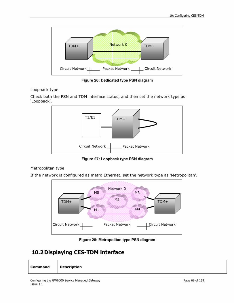
10: Configuring CES-TDM
Configuring the GW6000 Service Managed Gateway Page 69 of 159 Issue 1.1
TDM+
Network 0 TDM+
Packet Network Circuit Network Circuit Network
Figure 26: Dedicated type PSN diagram
Loopback type
Check both the PSN and TDM interface status, and then set the network type as ‘Loopback’.
TDM+
T1/E1
Packet Network Circuit Network
Figure 27: Loopback type PSN diagram
Metropolitan type
If the network is configured as metro Ethernet, set the network type as ‘Metropolitan’.
TDM+
M0
M1
M2
M3
M4
Network 0
Packet Network Circuit Network Circuit Network
TDM+
Figure 28: Metropolitan type PSN diagram
10.2 Displaying CES-TDM interface
Command Description

10: Configuring CES-TDM
Configuring the GW6000 Service Managed Gateway Page 70 of 159 Issue 1.1
show ces-tdm
Displays TDM configuration and status.
CES-TDM is configured only by the config ces-tdm command
In E1 frame mode
---------------------------------------------------------
Interface : E1 UNFRAME
Clock Mode : Loopback(Unframe)
Network Type : Dedicated
Tx Line Build Out : E1 120ohm
Line Code : HDB3
Underrun Byte : 255 [Hex:0xFF]
Idle Timing : Disable
---------------------------------------------------------
In T1 mode
---------------------------------------------------------
Interface : T1 UNFRAME
Clock Mode : Loopback(Unframe)
Network Type : Dedicated
Tx Line Build Out : T1 Short Haul 110FT
Line Code : AMI
Alarm Fast Detect : Disable
Underrun Byte : 255 [Hex:0xFF]
Idle Timing : Disable
---------------------------------------------------------
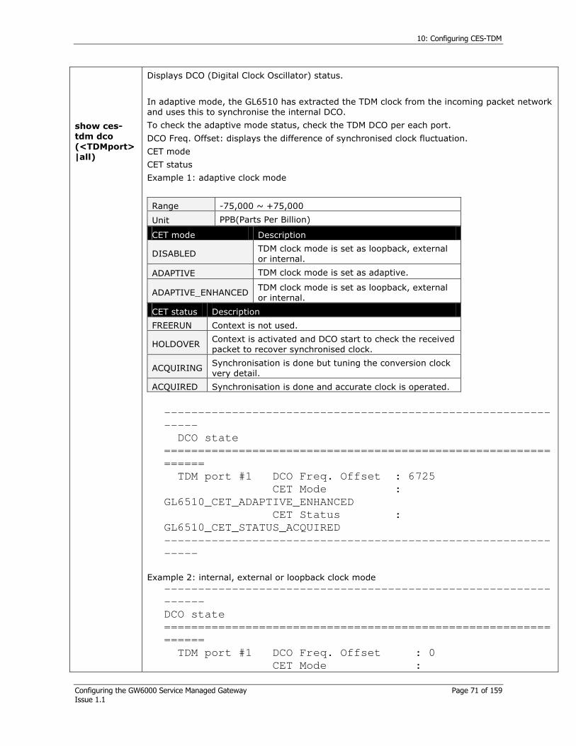
10: Configuring CES-TDM
Configuring the GW6000 Service Managed Gateway Page 71 of 159 Issue 1.1
show ces-
tdm dco
(<TDMport>
|all)
Displays DCO (Digital Clock Oscillator) status.
In adaptive mode, the GL6510 has extracted the TDM clock from the incoming packet network and uses this to synchronise the internal DCO.
To check the adaptive mode status, check the TDM DCO per each port.
DCO Freq. Offset: displays the difference of synchronised clock fluctuation.
CET mode
CET status
Example 1: adaptive clock mode
---------------------------------------------------------
-----
DCO state
=========================================================
======
TDM port #1 DCO Freq. Offset : 6725
CET Mode :
GL6510_CET_ADAPTIVE_ENHANCED
CET Status :
GL6510_CET_STATUS_ACQUIRED
---------------------------------------------------------
-----
Example 2: internal, external or loopback clock mode
---------------------------------------------------------
------
DCO state
=========================================================
======
TDM port #1 DCO Freq. Offset : 0
CET Mode :
Range -75,000 ~ +75,000
Unit PPB(Parts Per Billion)
CET mode Description
DISABLED TDM clock mode is set as loopback, external or internal.
ADAPTIVE TDM clock mode is set as adaptive.
ADAPTIVE_ENHANCED TDM clock mode is set as loopback, external or internal.
CET status Description
FREERUN Context is not used.
HOLDOVER Context is activated and DCO start to check the received packet to recover synchronised clock.
ACQUIRING Synchronisation is done but tuning the conversion clock very detail.
ACQUIRED Synchronisation is done and accurate clock is operated.

10: Configuring CES-TDM
Configuring the GW6000 Service Managed Gateway Page 72 of 159 Issue 1.1
GL6510_CET_DISABLED
CET Status :
GL6510_CET_STATUS_NONE
---------------------------------------------------------
------

11: Configuring CES-PSN
Configuring the GW6000 Service Managed Gateway Page 73 of 159 Issue 1.1
11 Configuring CES-PSN
GL6510 uses an internal Ethernet port route to encapsulated TDM data to (and from) the uplink port(s).
CES-PSN
Psuedo LAN port bridges to uplink port.
Packetizer Circuitizer
Figure 29: Configuring CES-PSN
GL6510’s psn port is hard wired as 100Mbps and full duplex only. If the uplink port’s link speed is set to 10Mbps, then TDM data transmission’s delay and loss could occur.
So if possible, the uplink port should be up as 100Mbps and full duplex mode.
11.1 Configurating using the config ces-psn command
For translating TDM data to packet type, you can assign destination IP and gateway address via CES-PSN commands interactively.
Command Description
PSN ip? [A.B.C.D/M]
Sets the ces-psn interface’s IP address. To establish encapsulated (by RTP-PW or MEF-PW) packet forwarding session, the Destination IP address is assigned mandatorily.
PSN gateway [A.B.C.D]
Sets the ces-psn interface’s default gateway.
PSN VLAN status? [enable|disable]
Enables/Disables the VLAN status. If PSN vlan status is enabled, the TDM data is encapsulated by adding 4bytes, VLAN tag field.

11: Configuring CES-PSN
Configuring the GW6000 Service Managed Gateway Page 74 of 159 Issue 1.1
PSN VLAN id ? [1-4094]
Sets the VLAN ID.
PSN IEEE 802.1p priority? [0-7]
Sets the VLAN 802.1p tag.
PSN Save the configuration? [yes|no] Saves the ces-psn configuration.
11.2 Configurating using the config ces-psn command
CES-PSN is virtual interface only for bridging context(s) between TDM and uplink ports
Command Description
show
ces-psn
Displays CES-PSN configuration.
-----------------------------------------------------------
CES PSN Configuration
===========================================================
IP address : 10.0.1.5
MAC address : 00-e0-1a-84-65-21
Subnet mask : 255.255.0.0
Default gateway IP : 10.20.254.101
VLAN status : enable
VLAN ID : 40
VLAN 802.1p priority : 0
-----------------------------------------------------------
show
ces-psn
pkc-stats
Displays the internal packet classifier counters.
Received
Protocol cnt Displays packets encapsulated RTP-pw, MEF-pw or MPLS-pw counter.
Protocol no match
Displays packets neither RTP-pw, MEF-pw or MPLS-pw encapsulated counter.
Classify no match
Displays encapsulated RTP-pw, MEF-pw or MPLS-pw packets are not classified to specific context counter.
Verify fail Displays encapsulated RTP-pw, MEF-pw or MPLS-pw but invalid packets counter.
IPv4 checksum Displays RTP-pw, MEF-pw or MPLS-pw encapsulation with invalid IP checksum counter.
show
ces-psn
pki-stats
Displays the internal packet counters.
Receive Total
BYTES RX Displays the received bytes in good and bad packets.
BYTES RX GOOD Displays the received bytes in good packets.

11: Configuring CES-PSN
Configuring the GW6000 Service Managed Gateway Page 75 of 159 Issue 1.1
FRAME RX Displays the received good and bad frame.
FRAME RX GOOD Displays the received good frame.
FLOW CTRL RX Displays the received pause frame.
MULTICAST RX Displays the received multicast frame.
BROADCAST RX Displays the received broadcast frame.
64 Displays the received 64bytes frames in good and bad packets.
65 TO 127 Displays the received 65~127bytes frames in good and bad packets.
128 TO 255 Displays the received 128~255bytes frames in good and bad packets.
256 TO 511 Displays the received 256~511bytes frames in good and bad packets.
512 TO 1023 Displays the received 512~1023bytes frames in good and bad packets.
1023 TO 1518 Displays the received 1024~1518bytes frames in good and bad packets.
JABBER Displays the received frames longer than max frame length with invalid CRC.
OVERSIZE Displays the received frames longer than max frame length with valid CRC.
FRAGMENT Displays the received frames shorter than 64 bytes with invalid CRC.
UNDERSIZE Displays the received frames shorter than 64 bytes with valid CRC.
ALIGNMENT Displays the received alignment errors.
CRC Displays the received CRC errors.
COLLISION Displays the received collision.
FILTER Displays the received filter counts.
Transmit Total
BYTES TX Displays the transmitted bytes in good and bad packets.
FRAME TX FAIL Displays the transmitted failure packets.
UNICAST TX Displays the transmitted unicast packets.
FLOW CTRL TX Displays the transmitted pause packets.
NON UCAST TX Displays the transmitted not unicast packets.
11.3 Clearing the CES-PSN packet counter
To monitor CES-PSN counters efficiently, clear the CES-PSN packet classifier and counter.
Command Description
set ces-psn pki-stats clear
Clear accumulated packet counter to 0.
set ces-psn pkc-stats clear Clear accumulated packet classification counter to 0.

12: Configuring CES-Context
Configuring the GW6000 Service Managed Gateway Page 76 of 159 Issue 1.1
12 Configuring CES-Context
Each stream of packets created by the packet assembler is called a Context in GL6510.
Context contains the information on how to manipulate the packets to be received or sent to TDM stream interfaces. To enable the encapsulation between the TDM stream and PSN packets, the context information contains a logical identifier (ID) to configure the end-to-end connection to transport TDM data over Packet Switch Network. So the context consists of the parameters including the TDM port (E1/T1), IP address, UDP port / ECID, LAN port and so on.
12.1 Context configuration using set command
Using set command, the context is configured without checking interaction.
Command Description
set ces-context (Context
ID|<Context List>)
(enable|disable)
Enables/Disables the context status. If the each context ID is specified and not enabled, the context is not used.
Available context ID for each product.
TDMGW11: 1-32
TDMGW21: 1-64
TDMGW41/4: 1-128
TDMGW8: 1-256
set ces-context (Context
ID|<Context List>)
dst-ip A.B.C.D
Sets the context destination IP address.
Each context’s destination IP address assignment is mandate.
set ces-context (Context
ID|<Context List>) dst-mac xx-xx-
xx-xx-xx-xx
Sets the context destination MAC address statically.
In TDM frame mode
set ces-context (Context
ID|<Context List>)
protocol (mef-pw|rtp-pw) timestamp
(bit|
byte) frames-per-packet (1-62)
Determines what kind of protocols, timestamp-increment and length of payload are employed for encapsulating on the pseudo wire in TDM frame mode.
Check the maximum frames-per-packet length as following:
Timestamp Interface RTP-PW MEF-PW
T1 42 42 Bit
E1 31 31
T1 60 62 Byte
E1 45 46

12: Configuring CES-Context
Configuring the GW6000 Service Managed Gateway Page 77 of 159 Issue 1.1
In TDM unframed mode
set ces-context (Context ID|<Context List>)
protocol (mef-pw|rtp-pw) timestamp (bit| byte) bytes-per-packet <1-1492>
Determines what kind of protocols, type of timestamp-increment and length of payload are employed for encapsulating on the pseudo wire in TDM unframed mode.
Check the maximum bytes-per-packet length as following.
Timestamp RTP-PW MEF-PW
Bit 1023 bytes 1023 bytes
Byte 1456 bytes 1492 bytes
set ces-context (Context
ID|<Context List>)
udp-dst-port <0-65535>
Specifies the transmission destination-point of pseudo wire connection. This value is valid when using the RTP protocol mode.
The RTP pseudo-wire connection between two end-points is established with the udpDestPort, udpSrcPort pair in reverse.
set ces-context (Context
ID|<Context List>)
udp-src-port <0-65535>
Specifies the transmission source-point of pseudo wire connection. This value is valid when using the RTP protocol mode.
The RTP pseudo-wire connection between two end-points is established with the udpDestPort, udpSrcPort pair.
set ces-context (Context
ID|<Context List>)
mef-ecid <0-1048575>
Specifies the transmission ECID of pseudo wire connection.
Virtual circuit or pseudo wire receiving identifier to distinguish it from other pseudo wire connection.
This value is valid when using the MEF-PW protocol mode.
set ces-context (Context
ID|<Context List>)
jitter-buffer <125-120,000>
Specifies the jitter buffer size to compensate for packet delay variation (PDV) that is present in the packet network. The value is configured with integer multiple of 125us.
set ces-context (Context
ID|<Context List>)
priority (high|highest|low|lowest)
Specifies the packet priority. The more the value is increased, the more often the packets in the queue are processed first.
set ces-context (Context
ID|<Context List>) tdm-port <1-4>
Specifies the TDM port to access. A grouped channel in the context is sent out using this port.
set ces-context Context ID tdm-
channel-list <ChannelList>
Specifies the available channels according to the interface type (E1 or T1). Each Channel can be marked with either a ‘1’or ‘0’. If this parameter is marked with

12: Configuring CES-Context
Configuring the GW6000 Service Managed Gateway Page 78 of 159 Issue 1.1
‘0’, no TDM data is accessed via this port.
set ces-context Context ID tdm-
first-channel <1-32>
Specifies which channel should appear at the start of each TDM frame.
Note that the first channel range is from 1 to 24 in T1 mode.
set ces-context copy Context ID
(Context
ID|<Context List>)
Copy a specified context to destined context(s). All of context parameters are copied to target.
12.2 Context configuration with config ces-context command
It is possible to configure TDM parameters interactively using the config command.
GL6510 CLI is recommended for configuring using config ces-context mode.
[value] means configurable value.
(value) means configured former value.
12.2.1 Frame mode/ RTP-PW type
On TDM frame and RTP-PW protocol mode, the frame per packet, ip-tos, UDP port number, and timestamp- increment, use the config ces-context command.
Notably in RTP-pw mode, the udp port number and the destination IP address combination should be used to create a unique packet network session.
To configure each context, enter config ces-context.
Command Description
Context ID? [Context ID]
Assigns the context ID to be configured.
Each product has different available contexts in frame mode:
TDMGW11: 1-32
TDMGW21: 1-64
TDMGW41: 1-128
TDMGW4: 1-128
TDMGW8: 1-256
Context #ID status? [enable|disable]
Sets the context status.
Context #ID protocol-type? [mef-pw|rtp-pw]
Sets the protocol type.
Context #ID dst-ip? [A.B.C.D]
Sets the destination IP address and bit mask.
Context #ID ip-tos? [0-255]
Sets the ToS field.

12: Configuring CES-Context
Configuring the GW6000 Service Managed Gateway Page 79 of 159 Issue 1.1
Context #ID udp-src-port? [0-65535]
Configures the UDP source port number.
Context #ID udp-dst-port? [0-65535]
Configures the UDP destination port number.
Context #ID jitter-buffer? [125-
120000]
Sets the Jitter buffer size.
Context #ID timestamp-increment?
[bit|byte]
Sets the timestamp increment type to bit or byte.
In bit type timestamp increment
Context #ID frames-per-pkt? [1-31]
Or
In byte type timestamp increment
Context #ID frames-per-pkt? [1-45]
Sets the number of frames per packet counts.
Context #ID tdm-port? [TDMport]
Specifies the TDM port to access. A grouped channel in the context is sent out using this port.
Context #ID tdm-channel-list? [ex: 1
or 1,2 or 1-32]
Specifies the available channels according to the interface type (E1 or T1).
Context #ID tdm-first-channel? [1-
24(T1), 1-32(E1)]
Specifies which channel should appear at the start of each frame.
Context #ID priority? [highest|
high|low|lowest]
Specifies the packet priority.
Context #ID save the configuration?
[Yes|No]
Saves the configuration.
12.2.2 Unframe mode/ RTP-PW type
On TDM unframed/ RTP-PW protocol mode, bytes per packet, ip-tos, UDP port number, and timestamp-increment use the config ces-context command.
Command Description
Context ID? [Context ID]
Assign the context ID to be configured.
Each product has different available contexts in unframe mode:
TDMGW11: 1
TDMGW21: 1-2
TDMGW41: 1-4
TDMGW4: 1-4
TDMGW8: 1-8
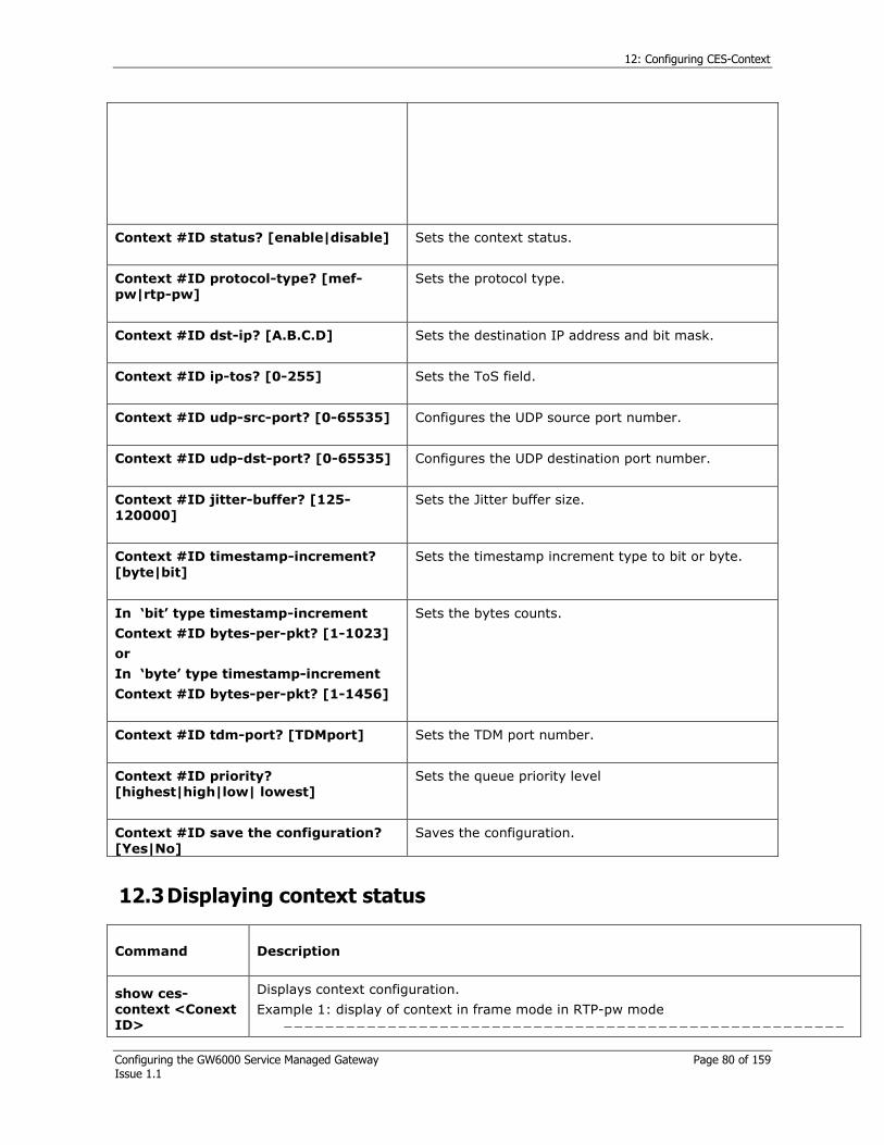
12: Configuring CES-Context
Configuring the GW6000 Service Managed Gateway Page 80 of 159 Issue 1.1
Context #ID status? [enable|disable]
Sets the context status.
Context #ID protocol-type? [mef-
pw|rtp-pw]
Sets the protocol type.
Context #ID dst-ip? [A.B.C.D]
Sets the destination IP address and bit mask.
Context #ID ip-tos? [0-255]
Sets the ToS field.
Context #ID udp-src-port? [0-65535]
Configures the UDP source port number.
Context #ID udp-dst-port? [0-65535]
Configures the UDP destination port number.
Context #ID jitter-buffer? [125-
120000]
Sets the Jitter buffer size.
Context #ID timestamp-increment?
[byte|bit]
Sets the timestamp increment type to bit or byte.
In ‘bit’ type timestamp-increment
Context #ID bytes-per-pkt? [1-1023]
or
In ‘byte’ type timestamp-increment
Context #ID bytes-per-pkt? [1-1456]
Sets the bytes counts.
Context #ID tdm-port? [TDMport]
Sets the TDM port number.
Context #ID priority?
[highest|high|low| lowest]
Sets the queue priority level
Context #ID save the configuration?
[Yes|No]
Saves the configuration.
12.3 Displaying context status
Command Description
show ces-
context <Conext
ID>
Displays context configuration.
Example 1: display of context in frame mode in RTP-pw mode
------------------------------------------------------
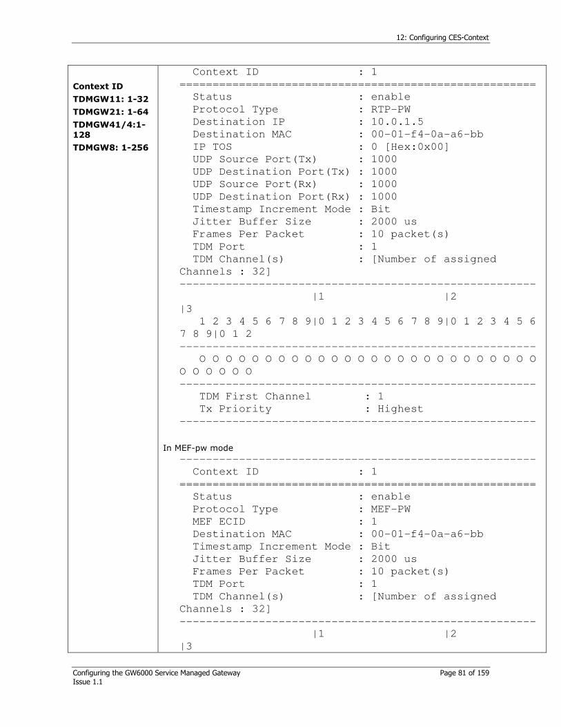
12: Configuring CES-Context
Configuring the GW6000 Service Managed Gateway Page 81 of 159 Issue 1.1
Context ID TDMGW11: 1-32
TDMGW21: 1-64
TDMGW41/4:1-
128
TDMGW8: 1-256
Context ID : 1
======================================================
Status : enable
Protocol Type : RTP-PW
Destination IP : 10.0.1.5
Destination MAC : 00-01-f4-0a-a6-bb
IP TOS : 0 [Hex:0x00]
UDP Source Port(Tx) : 1000
UDP Destination Port(Tx) : 1000
UDP Source Port(Rx) : 1000
UDP Destination Port(Rx) : 1000
Timestamp Increment Mode : Bit
Jitter Buffer Size : 2000 us
Frames Per Packet : 10 packet(s)
TDM Port : 1
TDM Channel(s) : [Number of assigned
Channels : 32]
------------------------------------------------------
|1 |2
|3
1 2 3 4 5 6 7 8 9|0 1 2 3 4 5 6 7 8 9|0 1 2 3 4 5 6
7 8 9|0 1 2
------------------------------------------------------
O O O O O O O O O O O O O O O O O O O O O O O O O O
O O O O O O
------------------------------------------------------
TDM First Channel : 1
Tx Priority : Highest
------------------------------------------------------
In MEF-pw mode
------------------------------------------------------
Context ID : 1
======================================================
Status : enable
Protocol Type : MEF-PW
MEF ECID : 1
Destination MAC : 00-01-f4-0a-a6-bb
Timestamp Increment Mode : Bit
Jitter Buffer Size : 2000 us
Frames Per Packet : 10 packet(s)
TDM Port : 1
TDM Channel(s) : [Number of assigned
Channels : 32]
------------------------------------------------------
|1 |2
|3
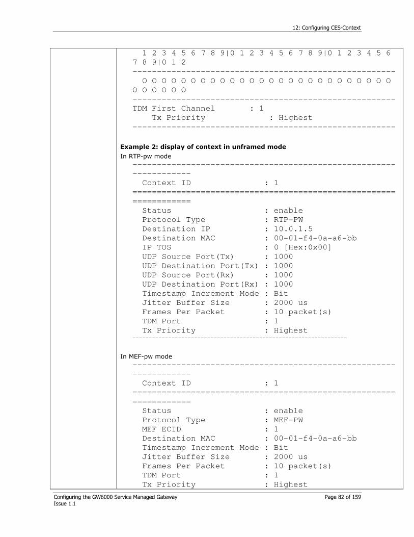
12: Configuring CES-Context
Configuring the GW6000 Service Managed Gateway Page 82 of 159 Issue 1.1
1 2 3 4 5 6 7 8 9|0 1 2 3 4 5 6 7 8 9|0 1 2 3 4 5 6
7 8 9|0 1 2
------------------------------------------------------
O O O O O O O O O O O O O O O O O O O O O O O O O O
O O O O O O
------------------------------------------------------
TDM First Channel : 1
Tx Priority : Highest
------------------------------------------------------
Example 2: display of context in unframed mode
In RTP-pw mode
------------------------------------------------------
------------
Context ID : 1
======================================================
============
Status : enable
Protocol Type : RTP-PW
Destination IP : 10.0.1.5
Destination MAC : 00-01-f4-0a-a6-bb
IP TOS : 0 [Hex:0x00]
UDP Source Port(Tx) : 1000
UDP Destination Port(Tx) : 1000
UDP Source Port(Rx) : 1000
UDP Destination Port(Rx) : 1000
Timestamp Increment Mode : Bit
Jitter Buffer Size : 2000 us
Frames Per Packet : 10 packet(s)
TDM Port : 1
Tx Priority : Highest ------------------------------------------------------------------
In MEF-pw mode
------------------------------------------------------
------------
Context ID : 1
======================================================
============
Status : enable
Protocol Type : MEF-PW
MEF ECID : 1
Destination MAC : 00-01-f4-0a-a6-bb
Timestamp Increment Mode : Bit
Jitter Buffer Size : 2000 us
Frames Per Packet : 10 packet(s)
TDM Port : 1
Tx Priority : Highest

12: Configuring CES-Context
Configuring the GW6000 Service Managed Gateway Page 83 of 159 Issue 1.1
------------------------------------------------------
-----------
show ces-
context list
Displays enabled or disabled context list.
Example 1: display of context list in frame mode
In Frame mode
All contexts are disabled in framed mode.
------------------------------------------------------
------------
Enabled Context List :
- - - - - - - - - - - -
- - -
…
- - - - - - - -
Disabled Context List :
1 2 3 4 5 6 7 8 9 10 11 12
13 14 15
…
121 122 123 124 125 126 127 128
------------------------------------------------------
------------
Example 2: display of context list in unframed mode
In unframed mode
You are only able to use 4 contexts in unframed mode
------------------------------------------------------
------------
Context Status Information
======================================================
============
Enabled Context List :
1 2 3 4
Disabled Context List :
- - - -
------------------------------------------------------
------------
show ces-
context protocol
Displays protocol usage per each context RTP-PW or MEF-PW.
Example 1: display in frame mode
------------------------------------------------------
-----------
Context Protocol Information
======================================================
==========
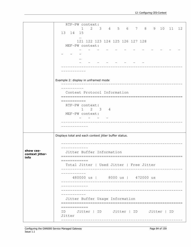
12: Configuring CES-Context
Configuring the GW6000 Service Managed Gateway Page 84 of 159 Issue 1.1
RTP-PW context:
1 2 3 4 5 6 7 8 9 10 11 12
13 14 15
…
121 122 123 124 125 126 127 128
MEF-PW context:
- - - - - - - - - - - -
- - -
…
- - - - - - - -
------------------------------------------------------
-----------
Example 2: display in unframed mode
------------------------------------------------------
----------
Context Protocol Information
======================================================
===========
RTP-PW context:
1 2 3 4
MEF-PW context:
- - - -
------------------------------------------------------
------------
show ces-
context jitter-
info
Displays total and each context jitter buffer status.
------------------------------------------------------
------------
Jitter Buffer Information
======================================================
============
Total Jitter | Used Jitter | Free Jitter
------------------------------------------------------
-----------
480000 us | 8000 us | 472000 us
------------------------------------------------------
------------
------------------------------------------------------
-----------
Jitter Buffer Usage Information
======================================================
============
ID Jitter | ID Jitter | ID Jitter | ID
Jitter
------------------------------------------------------

12: Configuring CES-Context
Configuring the GW6000 Service Managed Gateway Page 85 of 159 Issue 1.1
------------
1 : 2000us 2 : 2000us 3 : 2000us 4 :
2000us
------------------------------------------------------
------------
show ces-
context channels
(Portnumber|all)
Portnumber
TDMGW11: 1
TDMGW21: 1-2
TDMGW41/4: 1-
4
TDMGW8: 8
Displays TDM channels per each TDM port.
------------------------------------------------------
---------
TDM Port : 1
======================================================
=========
|1 |2
|3
1 2 3 4 5 6 7 8 9|0 1 2 3 4 5 6 7 8 9|0 1 2 3 4 5 6
7 8 9|0 1 2
----------------------------------------------------
-----------
O O O O O O O O O O O O O O O O O O O O O O O O O O
O O O O O O
------------------------------------------------------
---------
show ces-
context rx-status
<1-128|all >
Context ID
TDMGW11: 1-32
TDMGW21: 1-64
TDMGW41/4:1-
128
TDMGW8: 1-256
Displays received side’s context status.
------------------------------------------------------
---------
Rx State of enabled context(s)
======================================================
=========
Context #1 : state = active
------------------------------------------------------
---------
Rx-context queue is processed without buffering, so the state is indicated as active or not in use
show ces-
context tx-status
< 1-128|all>
Context ID
TDMGW11: 1-32
TDMGW21: 1-64
TDMGW41:1-128
TDMGW4: 1-128
TDMGW8: 1-256
Displays transmitted side’s context status.
------------------------------------------------------
---------
Tx State of enabled context(s)
======================================================
=========
Context #1
State = active Avg Length = 0.500
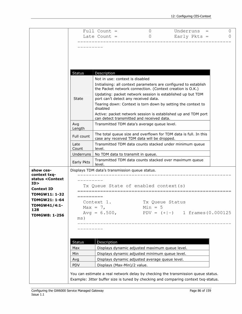
12: Configuring CES-Context
Configuring the GW6000 Service Managed Gateway Page 86 of 159 Issue 1.1
Full Count = 0 Underruns = 0
Late Count = 0 Early Pkts = 0
------------------------------------------------------
---------
Status Description
State
Not in use: context is disabled
Initialising: all context parameters are configured to establish the Packet network connection. (Context creation is O.K.)
Updating: packet network session is established up but TDM port can’t detect any received data.
Tearing down: Context is torn down by setting the context to disabled
Active: packet network session is established up and TDM port can detect transmitted and received data.
Avg Length
Transmitted TDM data’s average queue level.
Full count The total queue size and overflown for TDM data is full. In this case any received TDM data will be dropped.
Late Count
Transmitted TDM data counts stacked under minimum queue level.
Underruns No TDM data to transmit in queue.
Early Pkts Transmitted TDM data counts stacked over maximum queue level.
show ces-
context txq-
status <Context
ID>
Context ID
TDMGW11: 1-32
TDMGW21: 1-64
TDMGW41/4:1-
128
TDMGW8: 1-256
Displays TDM data’s transmission queue status.
------------------------------------------------------
---------
Tx Queue State of enabled context(s)
======================================================
=========
Context 1. Tx Queue Status
Max = 7, Min = 5
Avg = 6.500, PDV = (+|-) 1 frames(0.000125
ms)
------------------------------------------------------
---------
You can estimate a real network delay by checking the transmission queue status.
Example: Jitter buffer size is tuned by checking and comparing context txq-status.
Status Description
Max Displays dynamic adjusted maximum queue level.
Min Displays dynamic adjusted minimum queue level.
Avg Displays dynamic adjusted average queue level.
PDV Displays (Max-Min)/2 value.

12: Configuring CES-Context
Configuring the GW6000 Service Managed Gateway Page 87 of 159 Issue 1.1
If byte per pkt is set to 256 and show context txq-status displays as below:
------------------------------------------------------
---------
Tx Queue State of enabled context(s)
======================================================
=========
Context 1. Tx Queue Status
Max = 15, Min = 11
Avg = 14.500, PDV = (+|-) 2 frames(0.000250
ms) ---------------------------------------------------------------
then you can estimate packet delay in real network.
Estimated jitter buffer delay = (Avg – min) x Frame per pkt (or Bytes per pkt/32 (or 24)) x 125
= 3.5 x 8 x 125
= 3500us
It is recommended to configure context Jitter buffer delay as 3500us.
TDM (CES)
LAN (PSN)
Transmitted TDM data
Maximum level
Received packet data
Minimum level
Queue size
Tx context queue
Figure 29: Example of context tx queue

13: Configuring SNMP
Configuring the GW6000 Service Managed Gateway Page 88 of 159 Issue 1.1
13 Configuring SNMP
13.1 SNMP Introduction
SNMP (Simple Network Management Protocol) is the protocol that observes the operation of network devices defined as RFC of IETF and collects statistics, performance, and security information. It is the network management protocol used on most TCP/IP networks, although it is limited to the TCP/IP network. It exchanges MIB type data with the network device when the SNMP protocol is operating. When exchanging MIB, it uses four kinds of basic messages defined by the SNMP. By default, the SNMP is activated and read only, community is set to ‘public’, and the read/write community is set to ‘private’. The host receiving the SNMP trap signal is not defined. Therefore, the host IP needs to be registered to receive the trap signal.
SNMP/Trap manager
Circuit Network
Circuit Network
Packet
Switching
Figure 30: Example of SNMP configurations
13.2 SNMP Commands
Command Description
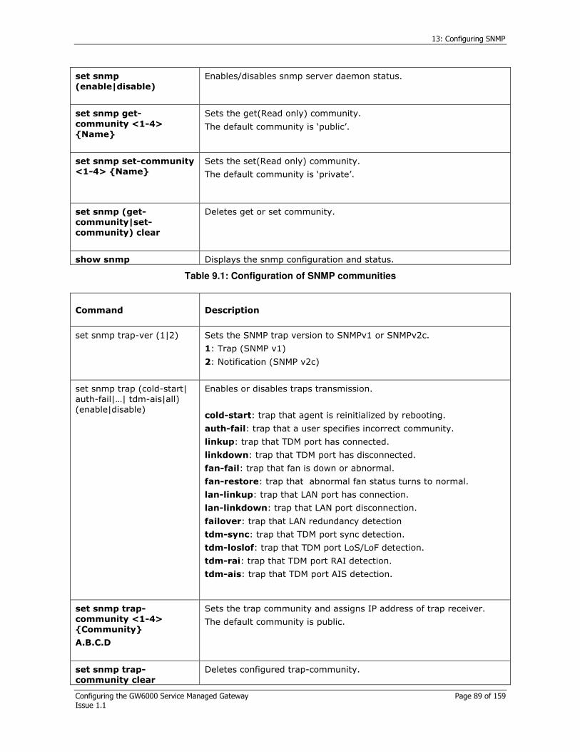
13: Configuring SNMP
Configuring the GW6000 Service Managed Gateway Page 89 of 159 Issue 1.1
set snmp
(enable|disable)
Enables/disables snmp server daemon status.
set snmp get-
community <1-4>
Name
Sets the get(Read only) community.
The default community is ‘public’.
set snmp set-community
<1-4> Name
Sets the set(Read only) community.
The default community is ‘private’.
set snmp (get-
community|set-
community) clear
Deletes get or set community.
show snmp Displays the snmp configuration and status.
Table 9.1: Configuration of SNMP communities
Command Description
set snmp trap-ver (1|2)
Sets the SNMP trap version to SNMPv1 or SNMPv2c.
1: Trap (SNMP v1)
2: Notification (SNMP v2c)
set snmp trap (cold-start| auth-fail|…| tdm-ais|all) (enable|disable)
Enables or disables traps transmission.
cold-start: trap that agent is reinitialized by rebooting.
auth-fail: trap that a user specifies incorrect community.
linkup: trap that TDM port has connected.
linkdown: trap that TDM port has disconnected.
fan-fail: trap that fan is down or abnormal.
fan-restore: trap that abnormal fan status turns to normal.
lan-linkup: trap that LAN port has connection.
lan-linkdown: trap that LAN port disconnection.
failover: trap that LAN redundancy detection
tdm-sync: trap that TDM port sync detection.
tdm-loslof: trap that TDM port LoS/LoF detection.
tdm-rai: trap that TDM port RAI detection.
tdm-ais: trap that TDM port AIS detection.
set snmp trap-
community <1-4>
Community
A.B.C.D
Sets the trap community and assigns IP address of trap receiver.
The default community is public.
set snmp trap-
community clear
Deletes configured trap-community.

13: Configuring SNMP
Configuring the GW6000 Service Managed Gateway Page 90 of 159 Issue 1.1
show snmp Display snmp configuration.
Table 38: Configuration of trap properties
GW6000# set snmp get-community 1 admin
Sets SNMP get-community as admin
GW6000# set snmp set-community 1 admin
Sets SNMP set-community as admin
GW6000# set snmp trap-ver 2
Sets SNMP trap version as SNMPv2C
GW6000# set snmp trap all disable
Sets SNMP traps to disable
GW6000# set snmp trap failover enable
Sets failover traps to enable
GW6000# set snmp trap-community 1 admin 10.20.1.67
Sets SNMP set-community as admin
GW6000# show snmp
Check the synchronised date and time from server
------------------------------------------------------------
-------------
SNMP (Simple Network Management System) Configuration
==============================================================
===========
SNMP server status enabled
SNMP trap PDU version SNMPv2c
------------------------------------------------------------
-------------
Get Community Name 1 admin Get
community
Get Community Name 2
Get Community Name 3
Get Community Name 4
------------------------------------------------------------
-------------
Set Community Name 1 admin Set
community
Set Community Name 2
Set Community Name 3
Set Community Name 4
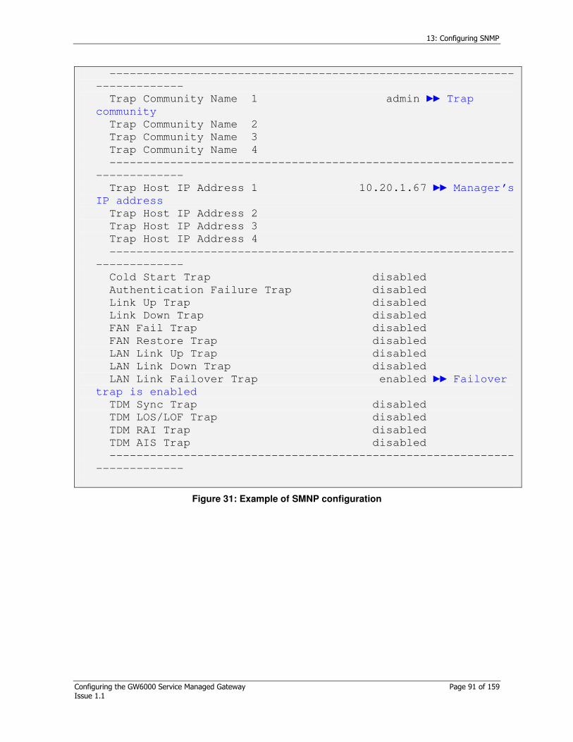
13: Configuring SNMP
Configuring the GW6000 Service Managed Gateway Page 91 of 159 Issue 1.1
------------------------------------------------------------
-------------
Trap Community Name 1 admin Trap
community
Trap Community Name 2
Trap Community Name 3
Trap Community Name 4
------------------------------------------------------------
-------------
Trap Host IP Address 1 10.20.1.67 Manager’s
IP address
Trap Host IP Address 2
Trap Host IP Address 3
Trap Host IP Address 4
------------------------------------------------------------
-------------
Cold Start Trap disabled
Authentication Failure Trap disabled
Link Up Trap disabled
Link Down Trap disabled
FAN Fail Trap disabled
FAN Restore Trap disabled
LAN Link Up Trap disabled
LAN Link Down Trap disabled
LAN Link Failover Trap enabled Failover
trap is enabled
TDM Sync Trap disabled
TDM LOS/LOF Trap disabled
TDM RAI Trap disabled
TDM AIS Trap disabled
------------------------------------------------------------
-------------
Figure 31: Example of SMNP configuration
14: Configuring NTP
Configuring the GW6000 Service Managed Gateway Page 92 of 159 Issue 1.1
14 Configuring NTP
14.1 NTP configuration
NTP (Network Time Protocol) is a protocol that allows the client or server time to be synchronised with a time source such as another server, a radio, or a satellite set top box, and to exchange the time with each other.
NTP is a higher layer protocol than TCP/IP and provides a 1/10,000,000 second unit time referring to several time sources. With the NTP server, time synchronisation can be set once or periodically. With GL6510, you synchronise the time periodically with a defined remote NTP server. When NTP is activated, the time synchronisation interval is set from 1 to 100 hours.
14.2 NTP Commands
Command Description
set ntp (enable|disable)
Enables or disables NTP daemon that synchronises the time periodically with the NTP server.
NTP is not activated if the NTP server IP is not defined.
set ntp add-server
A.B.C.D
Sets the NTP server IP address.
Up to 3 server IP addresses may be added.
set ntp delete-server
A.B.C.D
Deletes the NTP server IP address.
set ntp polling-interval
<1-100>
Sets the polling time period (hour) to get time from NTP server.
Set ntp delay-time
<disable|1-30>
Sets the delay time (second)
Disable: delay time is set as ‘0’ Table 39: NTP commands
GW6000# set ntp delay-time 30
Sets ntp delay time to 30 seconds
GW6000# set ntp add-server 10.20.252.7
Adds ntp server
GW6000# set ntp enable
Sets ntp client to enable

14: Configuring NTP
Configuring the GW6000 Service Managed Gateway Page 93 of 159 Issue 1.1
NTP is enabled System notifies NTP is enabled
GW6000# 28 Apr 10:24:57 ntpdate[218]: set time from server
10.20.252.7
System notifies date and time is synchronised from server
GW6000# show ntp
Displays NTP configuration
------------------------------------------------------------
-------------
Network Time Protocol Configuration
==============================================================
===========
NTP status : Enabled
NTP polling-interval : 1 hour
NTP Delay time : 5 second
server 1 : 10.20.252.7
--------------------------------------------------------------
-----------
GW6000# show date Check the synchronised date and time from
server
Thu Apr 28 10:25:22 GMT+9 2005
Figure 32: Example of NTP configuration

15: Configuring Access host
Configuring the GW6000 Service Managed Gateway Page 94 of 159 Issue 1.1
15 Configuring Access host
15.1 Access host introduction
GL6510 supports ‘Access host’ to a secure system from remote access. You can add an accessible host list using this function. When giving permission to a designated IP address, only that host is able to access to system remotely. By default, all hosts have the telnet authority to access the system.
15.1.1 Access host configuration commands
Command Description
set access-host
(enable|disable)
Allows or denies (Enables/Disables) remote (telnet, http and snmp) access to a device on a designated network.
set access-host
(add|delete) A.B.C.D
Adds or deletes access host.
show access-host Displays the Access host configuration.
Table 40: Access host commands and descriptions
To get a date and time from an NTP server, add the NTP’s server’s IP address to the access host list.

16: Monitoring via PMON counter
Configuring the GW6000 Service Managed Gateway Page 95 of 159 Issue 1.1
16 Monitoring via PMON counter
16.1 PMON counter
By using PMON counters, the GL6510 has PMON statistics and status. Through PMON statistics and status, you can check the number of errors, events and alarms on each access line. The parameters displayed depend on the TDM mode, T1 or E1.
16.1.1 PMON commands
The PMON commands count the number of errors or events for each E1 interface.
Command Description
show
ces-tdm
pmon
statistics
Displays errors-detected counts.
Example of display:
-----------------------------------------------------------
------------
PMON Statistics
===========================================================
============
TDM Port | ES(Error Second) SES(Severely ES)
UAS(Unavailable Second)
-----------------------------------------------------------
------------
1 | 0 1
0
2 | 1 1
0
3 | 1 1
0
4 | 0 1
0
-----------------------------------------------------------
Counter Description
ES (Error Second)
Displays one bit errors (CRC or LoF) during a second interval.
ES are not incremented during UAS.
SES (Severely ES)
SES is defined as a subset of ES.
If more 320 CRC or one or more LoF.
SES are not incremented during UAS.
UAS (Unavailable Sec.) Number of seconds during which the port is unable to transmit or receive traffic because of detection of 10 consecutive SES or ES.
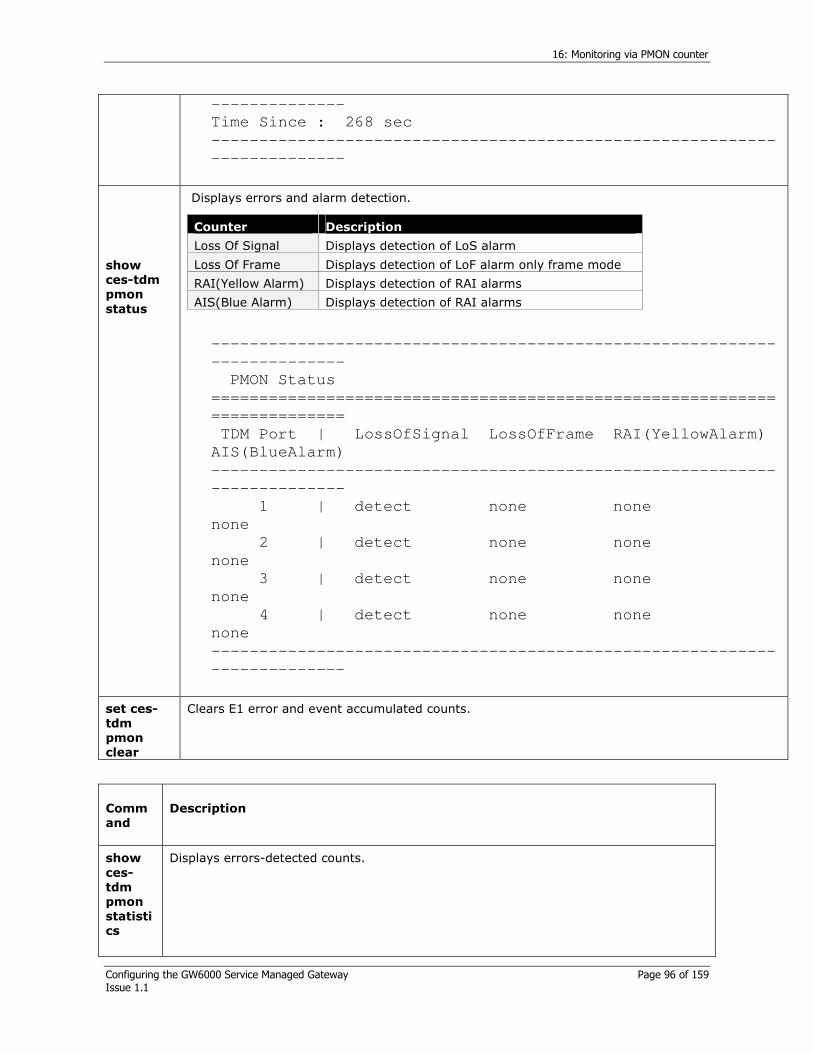
16: Monitoring via PMON counter
Configuring the GW6000 Service Managed Gateway Page 96 of 159 Issue 1.1
--------------
Time Since : 268 sec
-----------------------------------------------------------
--------------
show
ces-tdm
pmon
status
Displays errors and alarm detection.
-----------------------------------------------------------
--------------
PMON Status
===========================================================
==============
TDM Port | LossOfSignal LossOfFrame RAI(YellowAlarm)
AIS(BlueAlarm)
-----------------------------------------------------------
--------------
1 | detect none none
none
2 | detect none none
none
3 | detect none none
none
4 | detect none none
none
-----------------------------------------------------------
--------------
Counter Description
Loss Of Signal Displays detection of LoS alarm
Loss Of Frame Displays detection of LoF alarm only frame mode
RAI(Yellow Alarm) Displays detection of RAI alarms
AIS(Blue Alarm) Displays detection of RAI alarms
set ces-
tdm
pmon
clear
Clears E1 error and event accumulated counts.
Comm
and
Description
show
ces-
tdm
pmon
statisti
cs
Displays errors-detected counts.
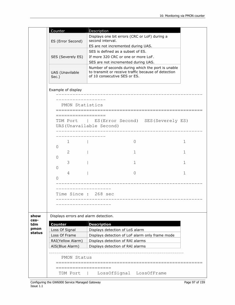
16: Monitoring via PMON counter
Configuring the GW6000 Service Managed Gateway Page 97 of 159 Issue 1.1
Example of display
-----------------------------------------------------
------------------
PMON Statistics
=====================================================
==================
TDM Port | ES(Error Second) SES(Severely ES)
UAS(Unavailable Second)
-----------------------------------------------------
------------------
1 | 0 1
0
2 | 1 1
0
3 | 1 1
0
4 | 0 1
0
-----------------------------------------------------
--------------------
Time Since : 268 sec
-----------------------------------------------------
--------------------
Counter Description
ES (Error Second)
Displays one bit errors (CRC or LoF) during a second interval.
ES are not incremented during UAS.
SES (Severely ES)
SES is defined as a subset of ES.
If more 320 CRC or one or more LoF.
SES are not incremented during UAS.
UAS (Unavilable Sec.)
Number of seconds during which the port is unable to transmit or receive traffic because of detection of 10 consecutive SES or ES.
show
ces-
tdm
pmon
status
Displays errors and alarm detection.
-------------------------------------------------------------------------
PMON Status
=====================================================
====================
TDM Port | LossOfSignal LossOfFrame
Counter Description
Loss Of Signal Displays detection of LoS alarm
Loss Of Frame Displays detection of LoF alarm only frame mode
RAI(Yellow Alarm) Displays detection of RAI alarms
AIS(Blue Alarm) Displays detection of RAI alarms

16: Monitoring via PMON counter
Configuring the GW6000 Service Managed Gateway Page 98 of 159 Issue 1.1
RAI(YellowAlarm) AIS(BlueAlarm)
-----------------------------------------------------
--------------------
1 | detect none none
none
2 | detect none none
none
3 | detect none none
none
4 | detect none none
none
-----------------------------------------------------
--------------------
set
ces-
tdm
pmon
clear
Clears E1 error and event accumulated counts.

17: Configuring SSL
Configuring the GW6000 Service Managed Gateway Page 99 of 159 Issue 1.1
17 Configuring SSL
The Secure Sockets Layer (SSL) is a common protocol for managing the security of a message transmission on the Internet. SSL has recently been succeeded by Transport Layer Security, which is based on SSL. SSL uses a program layer located between the Internet's Hypertext Transfer Protocol (HTTP) and Transport Control Protocol (TCP) layers.
17.1 Commands for SSL
Command Description
set system ssl
(enable|disable)
Enables/disables SSL.
show system
Displays SSL status.
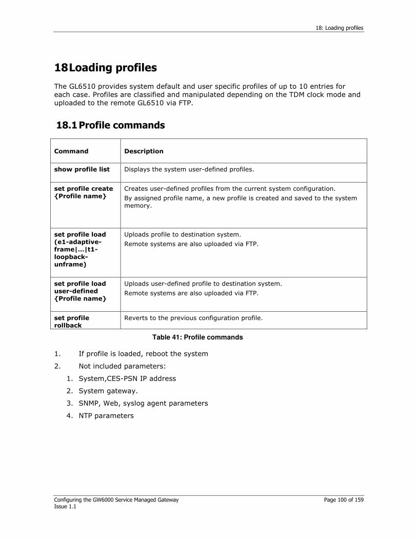
18: Loading profiles
Configuring the GW6000 Service Managed Gateway Page 100 of 159 Issue 1.1
18 Loading profiles
The GL6510 provides system default and user specific profiles of up to 10 entries for each case. Profiles are classified and manipulated depending on the TDM clock mode and uploaded to the remote GL6510 via FTP.
18.1 Profile commands
Command Description
show profile list
Displays the system user-defined profiles.
set profile create
Profile name
Creates user-defined profiles from the current system configuration.
By assigned profile name, a new profile is created and saved to the system memory.
set profile load
(e1-adaptive-
frame|…|t1-
loopback-
unframe)
Uploads profile to destination system.
Remote systems are also uploaded via FTP.
set profile load
user-defined
Profile name
Uploads user-defined profile to destination system.
Remote systems are also uploaded via FTP.
set profile
rollback
Reverts to the previous configuration profile.
Table 41: Profile commands
1. If profile is loaded, reboot the system
2. Not included parameters:
1. System,CES-PSN IP address
2. System gateway.
3. SNMP, Web, syslog agent parameters
4. NTP parameters
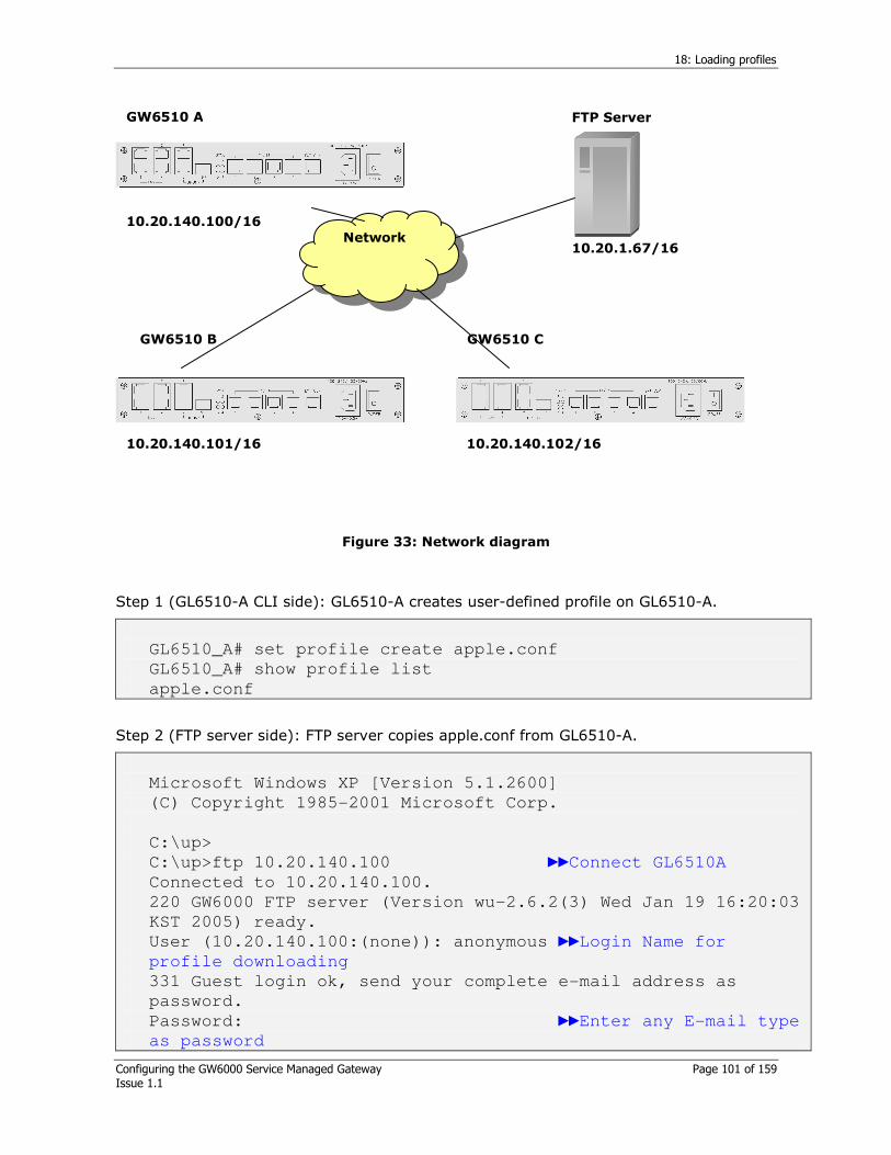
18: Loading profiles
Configuring the GW6000 Service Managed Gateway Page 101 of 159 Issue 1.1
FTP Server
Network
GW6510 A
GW6510 B GW6510 C
10.20.1.67/16
10.20.140.102/16 10.20.140.101/16
10.20.140.100/16
Figure 33: Network diagram
Step 1 (GL6510-A CLI side): GL6510-A creates user-defined profile on GL6510-A.
GL6510_A# set profile create apple.conf
GL6510_A# show profile list
apple.conf
Step 2 (FTP server side): FTP server copies apple.conf from GL6510-A.
Microsoft Windows XP [Version 5.1.2600]
(C) Copyright 1985-2001 Microsoft Corp.
C:\up>
C:\up>ftp 10.20.140.100 Connect GL6510A
Connected to 10.20.140.100.
220 GW6000 FTP server (Version wu-2.6.2(3) Wed Jan 19 16:20:03
KST 2005) ready.
User (10.20.140.100:(none)): anonymous Login Name for
profile downloading
331 Guest login ok, send your complete e-mail address as
password.
Password: Enter any E-mail type
as password
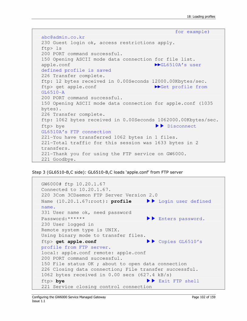
18: Loading profiles
Configuring the GW6000 Service Managed Gateway Page 102 of 159 Issue 1.1
for example)
230 Guest login ok, access restrictions apply.
ftp> ls
200 PORT command successful.
150 Opening ASCII mode data connection for file list.
apple.conf GL6510A’s user
defined profile is saved
226 Transfer complete.
ftp: 12 bytes received in 0.00Seconds 12000.00Kbytes/sec.
ftp> get apple.conf Get profile from
GL6510-A
200 PORT command successful.
150 Opening ASCII mode data connection for apple.conf (1035
bytes).
226 Transfer complete.
ftp: 1062 bytes received in 0.00Seconds 1062000.00Kbytes/sec.
ftp> bye Disconnect
GL6510A’s FTP connection
221-You have transferred 1062 bytes in 1 files.
221-Total traffic for this session was 1633 bytes in 2
transfers.
221-Thank you for using the FTP service on GW6000.
221 Goodbye.
Step 3 (GL6510-B,C side): GL6510-B,C loads ‘apple.conf’ from FTP server
GW6000# ftp 10.20.1.67
Connected to 10.20.1.67.
220 3Com 3CDaemon FTP Server Version 2.0
Name (10.20.1.67:root): profile Login user defined
name.
331 User name ok, need password
Password:****** Enters password.
230 User logged in
Remote system type is UNIX.
Using binary mode to transfer files.
ftp> get apple.conf Copies GL6510’s
profile from FTP server.
local: apple.conf remote: apple.conf
200 PORT command successful.
150 File status OK ; about to open data connection
226 Closing data connection; File transfer successful.
1062 bytes received in 0.00 secs (627.4 kB/s)
ftp> bye Exit FTP shell
221 Service closing control connection

18: Loading profiles
Configuring the GW6000 Service Managed Gateway Page 103 of 159 Issue 1.1
GW6000#
GW6000# show profile list Check the
profile is copied correctly
apple.conf
GW6000# set profile load user-defined apple.conf Loads the
profile
Press 'Y' or 'y' to load profile.
Please reboot now.
GW6000# reboot Reboot
system to apply the profile loading

19: Configuring RMON
Configuring the GW6000 Service Managed Gateway Page 104 of 159 Issue 1.1
19 Configuring RMON
19.1 RMON introduction
SNMP uses a method of periodically polling system information to analyze the network status. RMON (Remote network MONitoring) is a communication protocol that manages the network as an MIB type using a way of defining the network analyzing method (Control MIB), analyzing, and restoring the results on the system itself (Data MIB), and reporting it to the NMS. The SNMP has only Data MIB. RMON has two kinds of attributes: Control MIB and Data MIB, and analyzes the network according to the Control MIB definition and restores the results to the Data MIB Instance.
The GL6510 supports 1 (Statistics), 2 (History), 3 (Alarm), and 9 (Event) among the nine groups of RMON-I (RMON Lite ). RMON uses the same basic messages as the SET/GET message of the SNMP and several kinds of reports defined by RMON transfers as trap types. Therefore the manager that wants to receive a report from RMON should be set as a SNMP Trap Host first. The GL6510 allows you to configure the Control MIB for each group via the CLI or the Web in addition to the external RMON Manager. A Statistics Group creates a Table (etherStatsTable) according to the number of physical ports. Other group controls analyze the network according to each control after being set and activated by the user. The analyzed network results are displayed via the RMON exclusive manager and the SNMP MIB browser.
19.2 RMON configuration
19.2.1 RMON History group control configuration
Command Description
show rmon-control
history
Displays the RMON history control information.
set rmon history
(create|delete)
index <1-65535>
All controls are managed via an Index. This creates controls as mapping an Index with a history control using a command in advance. This command creates or removes a control using an index between 1~65535.
A maximum of 10 controls can be created. If a control is created, it is activated, the data source is IfIndex.1 (port 1), the bucket (a data column) has 50 entries, the sampling time is 30 minutes, and the owner name is ‘monitor’ by default.
If you then activate the control, a history data table is automatically created as an Instance type of MIB (Data MIB) according to the defined parameters.
set rmon history
(activate|deactivate)
<1-65535>
Activates/deactivates the defined RMON history control.

19: Configuring RMON
Configuring the GW6000 Service Managed Gateway Page 105 of 159 Issue 1.1
set rmon history
data-source <1-24>
INDEX
Sets the data source port for the defined RMON history control.
Enter the real source port number as the source port.
set rmon history
request-bucket <1-
100> <1-65535>
Changes the bucket size for the defined RMON history control.
set rmon history
sample-interval <1-
3600> <1-65535>
Sets the sampling time from between 1~3600 seconds for the defined RMON history control.
set rmon history
owner
OWNER_NAME
<1-65535>
Sets the owner name for the defined RMON history control. The name can be up to 32 characters and spaces are not allowed.
Table 42: RMON history group control configuration
19.2.2 RMON alarm group/event control configuration
Command Description
show rmon-control
alarm
Displays the RMON alarm control information.
show rmon-control
event
Displays the RMON event control information.
set rmon alarm
create index <1-
65535> f-event <1-
65535> r-event <1-
65535>
One alarm control is connected to 2 event controls (falling event, rising event) and therefore the falling and rising event indexes need to be entered together when creating an alarm control. A maximum of 10 alarm controls can be created. When an alarm control is created, the falling event control and the rising event control are coordinated. According to the content of the alarm Control, you can use both of them or none of them but the relationship is always maintained for the next usage. The initial value when creating an Alarm control is as follows:
Alarm control
Active Activate
Owner Name monitor
Falling threshold 3
Rising threshold 200
Sample type Absolute
Alarm variable etherStatsPkts. 1
Alarm OID 1.3.6.1.2.1.16.1.1.1.5.1
Startup alarm Both
Sampling interval 1 second
Alarm value 0
Falling event control

19: Configuring RMON
Configuring the GW6000 Service Managed Gateway Page 106 of 159 Issue 1.1
Active Activate
Owner Name monitor
Community Name public
Description admin-FallingEvent
Event type Event Log and Trap
Rising event control
Active Activate
Owner Name monitor
Community Name public
Description admin-RisingEvent
Event type Event Log and Trap
Command Description
set rmon alarm remove
index <1-65535>
Removes the registered RMON alarm control. The event controls cooperating with the alarm control are also removed.
set rmon alarm owner
OWNER_NAME <1-
65535>
Sets the owner name for the defined RMON alarm control. This can be up to 32 characters and spaces are not allowed.
set rmon alarm
(activate|deactivate) <1-
65535>
Activates/deactivates the defined RMON alarm control.
set rmon alarm (falling-
threshold|rising-
threshold) <1-65535>
Sets the falling threshold or rising threshold from 1~65535 for the defined RMON alarm control.
set rmon alarm sample-
interval <1-3600><1-
65535>
Sets the sampling interval from between 1~3600 seconds for the defined RMON alarm control.
set rmon alarm sample-
type (absolute|delta) <1-
65535>
Sets the sample type as ‘absolute’ or as ‘delta’ type for the defined RMON alarm control.
set rmon alarm
startup_alarm
(none|rising|falling|both)
<1-65535>
Sets the startup alarm for the defined RMON alarm control.
set rmon alarm sample-
variable OID <1-65535>
Sets the OID for the defined RMON alarm control.
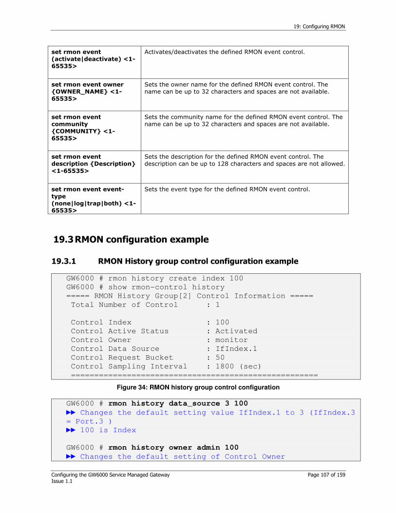
19: Configuring RMON
Configuring the GW6000 Service Managed Gateway Page 107 of 159 Issue 1.1
set rmon event
(activate|deactivate) <1-
65535>
Activates/deactivates the defined RMON event control.
set rmon event owner
OWNER_NAME <1-
65535>
Sets the owner name for the defined RMON event control. The name can be up to 32 characters and spaces are not available.
set rmon event
community
COMMUNITY <1-
65535>
Sets the community name for the defined RMON event control. The name can be up to 32 characters and spaces are not available.
set rmon event
description Description
<1-65535>
Sets the description for the defined RMON event control. The description can be up to 128 characters and spaces are not allowed.
set rmon event event-
type
(none|log|trap|both) <1-
65535>
Sets the event type for the defined RMON event control.
19.3 RMON configuration example
19.3.1 RMON History group control configuration example
GW6000 # rmon history create index 100
GW6000 # show rmon-control history
===== RMON History Group[2] Control Information =====
Total Number of Control : 1
Control Index : 100
Control Active Status : Activated
Control Owner : monitor
Control Data Source : IfIndex.1
Control Request Bucket : 50
Control Sampling Interval : 1800 (sec)
=====================================================
Figure 34: RMON history group control configuration
GW6000 # rmon history data_source 3 100
Changes the default setting value IfIndex.1 to 3 (IfIndex.3
= Port.3 )
100 is Index
GW6000 # rmon history owner admin 100
Changes the default setting of Control Owner
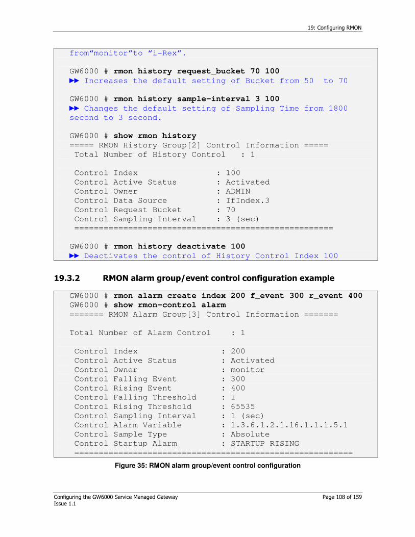
19: Configuring RMON
Configuring the GW6000 Service Managed Gateway Page 108 of 159 Issue 1.1
from“monitor”to “i-Rex”.
GW6000 # rmon history request_bucket 70 100
Increases the default setting of Bucket from 50 to 70
GW6000 # rmon history sample-interval 3 100
Changes the default setting of Sampling Time from 1800
second to 3 second.
GW6000 # show rmon history
===== RMON History Group[2] Control Information =====
Total Number of History Control : 1
Control Index : 100
Control Active Status : Activated
Control Owner : ADMIN
Control Data Source : IfIndex.3
Control Request Bucket : 70
Control Sampling Interval : 3 (sec)
=====================================================
GW6000 # rmon history deactivate 100
Deactivates the control of History Control Index 100
19.3.2 RMON alarm group/event control configuration example
GW6000 # rmon alarm create index 200 f_event 300 r_event 400
GW6000 # show rmon-control alarm
======= RMON Alarm Group[3] Control Information =======
Total Number of Alarm Control : 1
Control Index : 200
Control Active Status : Activated
Control Owner : monitor
Control Falling Event : 300
Control Rising Event : 400
Control Falling Threshold : 1
Control Rising Threshold : 65535
Control Sampling Interval : 1 (sec)
Control Alarm Variable : 1.3.6.1.2.1.16.1.1.1.5.1
Control Sample Type : Absolute
Control Startup Alarm : STARTUP RISING
=========================================================
Figure 35: RMON alarm group/event control configuration

19: Configuring RMON
Configuring the GW6000 Service Managed Gateway Page 109 of 159 Issue 1.1
GW6000# rmon alarm falling-threshold 3 200
Changes the default setting of falling threshold from 0 to
3. (200 is Index)
GW6000# rmon alarm rising-threshold 100 200
Changes the default setting of rising threshold from 65535
to 100.
GW6000# rmon alarm owner admin 200
Changes the default setting of Control Owner from
“monitor” to “i-Rex”
GW6000# rmon alarm sample-interval 3 200
Changes the default setting of sampling time from 1second
to 3 second.
GW6000# rmon alarm sample-type delta 200
Changes the default setting of Absolute to Delta ( by the
range of change)
GW6000# rmon alarm sample-variable 1.3.6.1.2.1.16.1.1.1.5.2
200
Changes the default setting of etherStatsPks.1 to
etherStatsPks.2
It is changeable to other MIB (ex, No. of TCP Connection)
GW6000# rmon alarm startup-alarm both 200
The Default setting is activating the Both (falling/rising)
events but if necessary, it is possible to change to Rising
only, Falling only, or None
GW6000# show rmon-control alarm
===== RMON Alarm Group[3] Control Information =====
Total Number of Alarm Control : 1
Control Index : 200
Control Active Status : Activated
Control Owner : admin
Control Falling Event : 300
Control Rising Event : 400
Control Falling Threshold : 3
Control Rising Threshold : 100
Control Sampling Interval : 3 (sec)
Control Alarm Variable : 1.3.6.1.2.1.16.1.1.1.5.2
Control Sample Type : Delta
Control Startup Alarm : BOTH
=====================================================
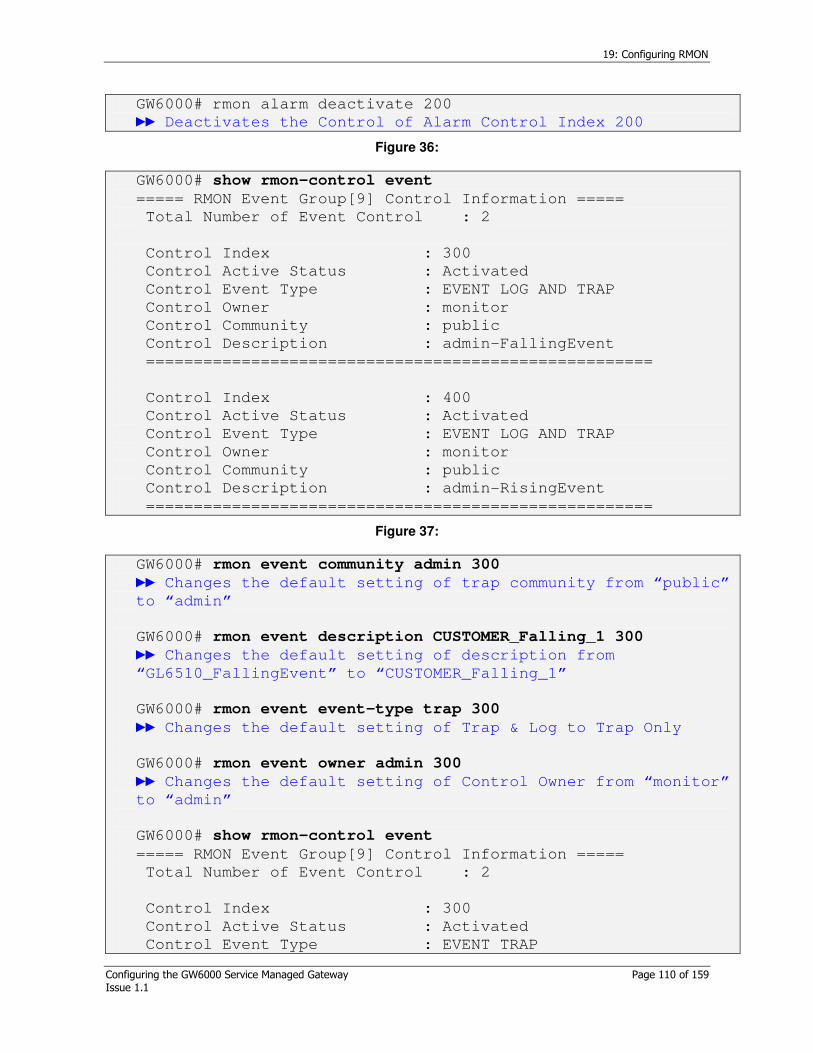
19: Configuring RMON
Configuring the GW6000 Service Managed Gateway Page 110 of 159 Issue 1.1
GW6000# rmon alarm deactivate 200
Deactivates the Control of Alarm Control Index 200
Figure 36:
GW6000# show rmon-control event
===== RMON Event Group[9] Control Information =====
Total Number of Event Control : 2
Control Index : 300
Control Active Status : Activated
Control Event Type : EVENT LOG AND TRAP
Control Owner : monitor
Control Community : public
Control Description : admin-FallingEvent
=====================================================
Control Index : 400
Control Active Status : Activated
Control Event Type : EVENT LOG AND TRAP
Control Owner : monitor
Control Community : public
Control Description : admin-RisingEvent
=====================================================
Figure 37:
GW6000# rmon event community admin 300
Changes the default setting of trap community from “public”
to “admin”
GW6000# rmon event description CUSTOMER_Falling_1 300
Changes the default setting of description from
“GL6510_FallingEvent” to “CUSTOMER_Falling_1”
GW6000# rmon event event-type trap 300
Changes the default setting of Trap & Log to Trap Only
GW6000# rmon event owner admin 300
Changes the default setting of Control Owner from “monitor”
to “admin”
GW6000# show rmon-control event
===== RMON Event Group[9] Control Information =====
Total Number of Event Control : 2
Control Index : 300
Control Active Status : Activated
Control Event Type : EVENT TRAP
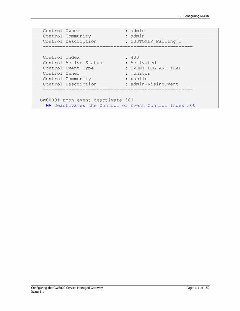
19: Configuring RMON
Configuring the GW6000 Service Managed Gateway Page 111 of 159 Issue 1.1
Control Owner : admin
Control Community : admin
Control Description : CUSTOMER_Falling_1
=====================================================
Control Index : 400
Control Active Status : Activated
Control Event Type : EVENT LOG AND TRAP
Control Owner : monitor
Control Community : public
Control Description : admin-RisingEvent
=====================================================
GW6000# rmon event deactivate 300
Deactivates the Control of Event Control Index 300

Appendix A: Configuring Clock mode
Configuring the GW6000 Service Managed Gateway Page 112 of 159 Issue 1.1
Appendix A: Configuring Clock mode
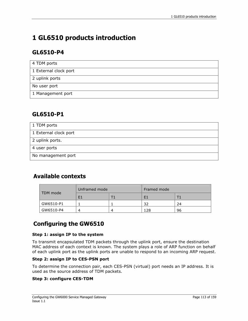
1 GL6510 products introduction
Configuring the GW6000 Service Managed Gateway Page 113 of 159 Issue 1.1
1 GL6510 products introduction
GL6510-P4
4 TDM ports
1 External clock port
2 uplink ports
No user port
1 Management port
GL6510-P1
1 TDM ports
1 External clock port
2 uplink ports.
4 user ports
No management port
Available contexts
Unframed mode Framed mode TDM mode
E1 T1 E1 T1
GW6510-P1 1 1 32 24
GW6510-P4 4 4 128 96
Configuring the GW6510
Step 1: assign IP to the system
To transmit encapsulated TDM packets through the uplink port, ensure the destination MAC address of each context is known. The system plays a role of ARP function on behalf of each uplink port as the uplink ports are unable to respond to an incoming ARP request.
Step 2: assign IP to CES-PSN port
To determine the connection pair, each CES-PSN (virtual) port needs an IP address. It is used as the source address of TDM packets.
Step 3: configure CES-TDM

1 GL6510 products introduction
Configuring the GW6000 Service Managed Gateway Page 114 of 159 Issue 1.1
CES-TDM determines the TDM properties dedicated to T1/E1 standard such as LBO, Line Coding, Clock Mode, Underrun Byte and Idle Timing.
Step 4: configure CES-Context
Context configures the connection end-points by specifying encapsulation protocol type, protocol parameters, jitter buffer, packet length and channel information if framed mode is used.

20: Examples based on TDM clock mode
Configuring the GW6000 Service Managed Gateway Page 115 of 159 Issue 1.1
20 Examples based on TDM clock mode
Table 43: Examples of TDM clock mode
*From Rx means the clock is extracted from the received clock signal.
Framing type
Example Circuit-A GL6510 A GL6510 B Circuit-B
Case I From Rx External Adaptive-avg or rpt From Rx
Case II From Rx Internal Adaptive-avg or rtp From Rx Frame
Case III Internal Adaptive-avg or rtp
Adaptive-avg or rtp From Rx
Case IV Internal Loopback Adaptive-avg or rtp From-Rx
Case V From Rx Internal Adaptive-avg or rtp From-Rx
Case VI From Rx Differential Differential From-Rx Unframed
Case VII Internal Adaptive-avg or rtp
Adaptive-avg or rtp From Rx
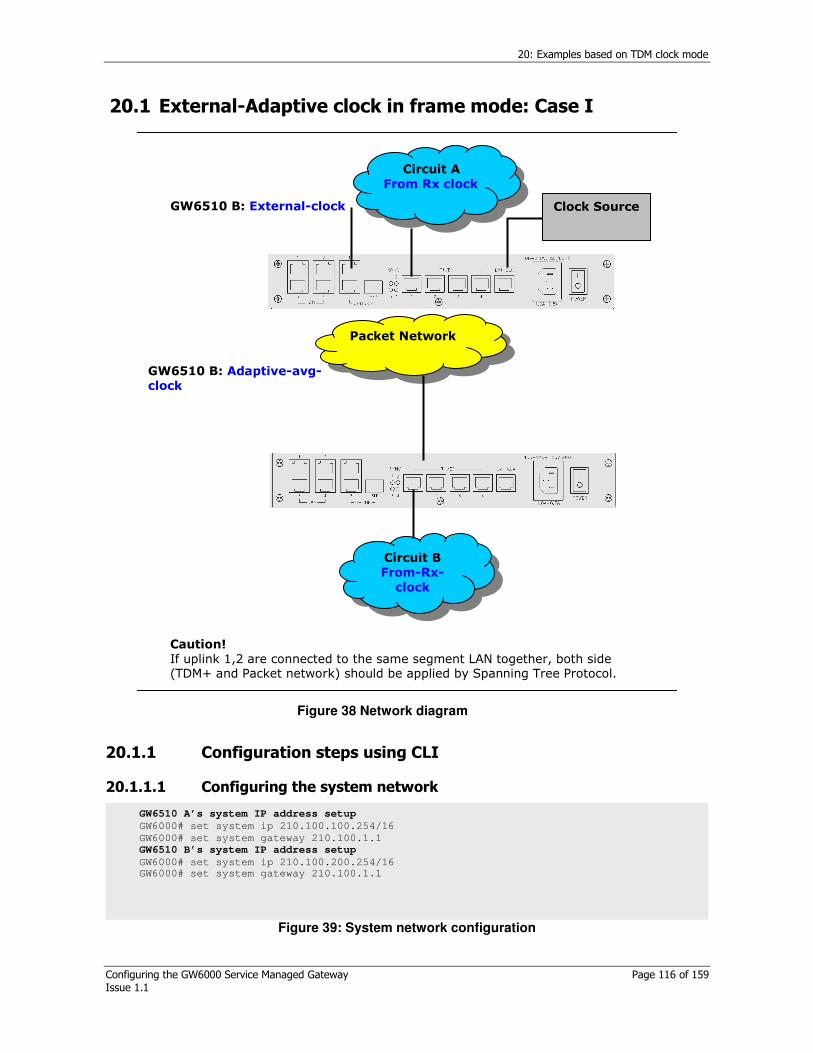
20: Examples based on TDM clock mode
Configuring the GW6000 Service Managed Gateway Page 116 of 159 Issue 1.1
20.1 External-Adaptive clock in frame mode: Case I
Caution! If uplink 1,2 are connected to the same segment LAN together, both side (TDM+ and Packet network) should be applied by Spanning Tree Protocol.
Circuit A
From Rx clock
Circuit B From-Rx-
clock
GW6510 B: External-clock
GW6510 B: Adaptive-avg-clock
Packet Network
Clock Source
Figure 38 Network diagram
20.1.1 Configuration steps using CLI
20.1.1.1 Configuring the system network
Figure 39: System network configuration
GW6510 A’s system IP address setup
GW6000# set system ip 210.100.100.254/16
GW6000# set system gateway 210.100.1.1
GW6510 B’s system IP address setup
GW6000# set system ip 210.100.200.254/16 GW6000# set system gateway 210.100.1.1

20: Examples based on TDM clock mode
Configuring the GW6000 Service Managed Gateway Page 117 of 159 Issue 1.1
Figure 37: GW6510-A’s CES-PSN configuration
Figure 40: GW6510-B’s CES-PSN configuration
GW6510 A’s CES-PSN setup TDM-GW# config ces-psn
% Press 'Ctrl-X' to exit config process
% Press 'Enter' to keep the previous value
PSN ip? [A.B.C.D/M] (10.20.250.101/16)
> 210.100.100.253/16
Network prefix of management and LAN port SHOULD be exactly equal(mandated)
PSN gateway? [A.B.C.D] (10.20.254.101)
> 210.100.100.1
The network prefix of management and LAN port SHOULD be matched exactly to avoid
malfunctioning of ARP
PSN VLAN status? [enable|disable] (disable)
> disable
PSN Save the configuration? [yes|no] (yes)
GW6510 B’s CES-PSN setup
TDM-GW# config ces-psn
% Press 'Ctrl-X' to exit config process
% Press 'Enter' to keep the previous value
PSN ip? [A.B.C.D/M] (10.20.250.101/16)
> 210.100.200.253/16
PSN gateway? [A.B.C.D] (10.20.254.101)
> 210.100.100.1
PSN VLAN status? [enable|disable] (disable)
> disable
PSN Save the configuration? [yes|no] (yes)
> yes

20: Examples based on TDM clock mode
Configuring the GW6000 Service Managed Gateway Page 118 of 159 Issue 1.1
20.1.1.2 CES-TDM configuration

20: Examples based on TDM clock mode
Configuring the GW6000 Service Managed Gateway Page 119 of 159 Issue 1.1
n
GW6510 A’s TDM setup
GW6000# config ces-tdm TDM can be configured by ‘config ces-tdm’ command.
% Press 'Ctrl-X' to exit config process
% Press 'Enter' to keep the previous value
TDM interface ? [e1|e1-crc-mfrm|e1-unframe|t1-sf|t1-dm|t1-slc96|t1-dm-fdl|t1-esf|t1-sf-
jpn-
alarm|t1-dm-jpn-alarm|t1-slc96-jpn-alarm||t1-dm-fdl-jpn-alarm|t1-jt-g704|t1-unframe]
(e1-crc-mfrm)
> e1-crc-mfrm Set TDM interface type as (E1 CRC Multiframe)framed mode
TDM clock-mode ? [internal-frame|external-frame|adaptive-rtp-frame|adaptive-avg-frame]
(internal-frame)
> external-frame Set TDM clock mode as external clock
TDM net-type ? [dedicated|metropolitan|continental|loopback] (metropolitan)
> dedicated Set network type as dedicated
TDM line-build-out ? [e1-75ohm|e1-120ohm] (e1-120ohm)
> e1-120ohm Set TDM line impedance as 120ohm
TDM line-code ? [ami|hdb3-e1] (hdb3-e1)
> hdb3-e1 Set TDM line coding as hdb3-e1
TDM underrun-byte ? [0-255] (255)
> 255 Set underrun byte pattern as 0xFF
TDM idle-timing ? [enable|disable] (enable)
> disable Set idle timing to disable
TDM save the configuration ? [Yes|No] (Yes)
> yes
The system should be restarted to apply the changes.
Press 'Y' or 'y' to reboot system ...
-------------------------------------------------------------------------
Interface : E1 CRC MFRM
Clock Mode : External(Frame)
Network Type : Dedicated
Tx Line Build Out : E1 120ohm
Line Code : HDB3
Underrun Byte : 255 [Hex:0xff]
Idle Timing : Disable
-------------------------------------------------------------------------
TDM Port | LossOfSignal LossOfFrame RAI(YellowAlarm) AIS(BlueAlarm)
=========================================================================
1 | none none none none
2 | detect detect none none
3 | detect detect none none
4 | detect detect none none
-------------------------------------------------------------------------
..TDM interface has been changed, so CONTEXT has been initialized.
The system should be rebooted to apply the changes.
Press 'Y' or 'y' to reboot ...
If TDM interface is changed, contexts are initialised as factory default.
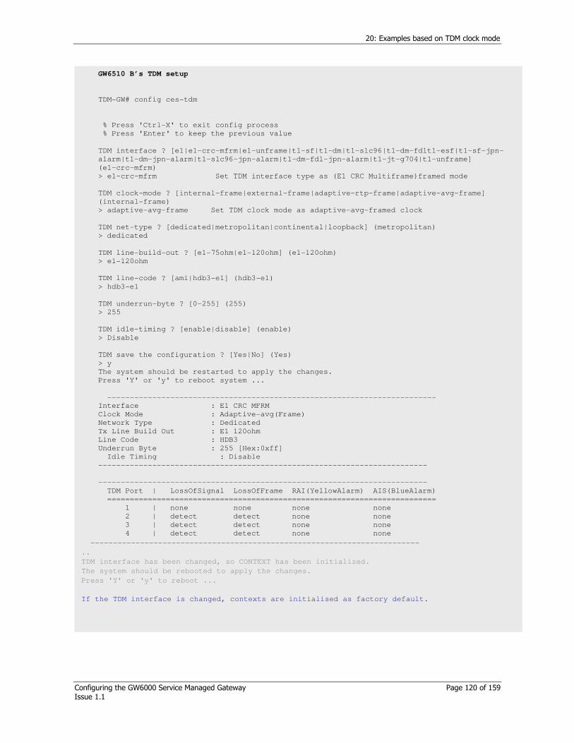
20: Examples based on TDM clock mode
Configuring the GW6000 Service Managed Gateway Page 120 of 159 Issue 1.1
GW6510 B’s TDM setup
TDM-GW# config ces-tdm
% Press 'Ctrl-X' to exit config process
% Press 'Enter' to keep the previous value
TDM interface ? [e1|e1-crc-mfrm|e1-unframe|t1-sf|t1-dm|t1-slc96|t1-dm-fdlt1-esf|t1-sf-jpn-
alarm|t1-dm-jpn-alarm|t1-slc96-jpn-alarm|t1-dm-fdl-jpn-alarm|t1-jt-g704|t1-unframe]
(e1-crc-mfrm)
> e1-crc-mfrm Set TDM interface type as (E1 CRC Multiframe)framed mode
TDM clock-mode ? [internal-frame|external-frame|adaptive-rtp-frame|adaptive-avg-frame]
(internal-frame)
> adaptive-avg-frame Set TDM clock mode as adaptive-avg-framed clock
TDM net-type ? [dedicated|metropolitan|continental|loopback] (metropolitan)
> dedicated
TDM line-build-out ? [e1-75ohm|e1-120ohm] (e1-120ohm)
> e1-120ohm
TDM line-code ? [ami|hdb3-e1] (hdb3-e1)
> hdb3-e1
TDM underrun-byte ? [0-255] (255)
> 255
TDM idle-timing ? [enable|disable] (enable)
> Disable
TDM save the configuration ? [Yes|No] (Yes)
> y
The system should be restarted to apply the changes.
Press 'Y' or 'y' to reboot system ...
-------------------------------------------------------------------------
Interface : E1 CRC MFRM
Clock Mode : Adaptive-avg(Frame)
Network Type : Dedicated
Tx Line Build Out : E1 120ohm
Line Code : HDB3
Underrun Byte : 255 [Hex:0xff]
Idle Timing : Disable
-------------------------------------------------------------------------
-------------------------------------------------------------------------
TDM Port | LossOfSignal LossOfFrame RAI(YellowAlarm) AIS(BlueAlarm)
=========================================================================
1 | none none none none
2 | detect detect none none
3 | detect detect none none
4 | detect detect none none
-------------------------------------------------------------------------
..
TDM interface has been changed, so CONTEXT has been initialized.
The system should be rebooted to apply the changes.
Press 'Y' or 'y' to reboot ...
If the TDM interface is changed, contexts are initialised as factory default.

20: Examples based on TDM clock mode
Configuring the GW6000 Service Managed Gateway Page 121 of 159 Issue 1.1
20.1.1.3 CES-Context configuration
GW6510 A side CES-Context setup
GW6000# config ces-context Context can be configured by ‘config ces-context’ command.
Context ID ? [1-128] (1)
> 1
Context #1 status ? [enable|disable] (enable)
> enable
Context #1 dst-ip ? [A.B.C.D] (10.0.1.5)
> 210.100.200.253 Set the destination IP encapsulated TDM data is forwarded to.
Context #1 protocol-type ? [mef-pw|rtp-pw] (rtp-pw)
> rtp-pw
Context #1 ip-tos ? [0-255] (0)
> 0
Context #1 udp-src-port ? [0-65535] (1000)
> 1000
Context #1 udp-dst-port ? [0-65535] (1000)
> 1000
Context #1 jitter-buffer ? [125-120000] (0)
> 2000 Jitter buffer can be adjusted network environment.
Refer to application notes by Virtual Access.
Context #1 timestamp-increment ? [byte|bit] (bit)
> bit
Context #1 frames-per-pkt ? [1-31] (8)
> 8 In frame mode, Payload length is set by frame-per-pkt.
Refer to application notes by Virtual Access.
Context #1 tdm-port ? [1-4] (1)
> 1
TDM Port : 1
TDM Channel(s) Assignment
---------------------------------------------------------------
|1 |2 |3
1 2 3 4 5 6 7 8 9|0 1 2 3 4 5 6 7 8 9|0 1 2 3 4 5 6 7 8 9|0 1 2
---------------------------------------------------------------
O O O O O O O O O O O O O O O O O O O O O O O O O O O O O O O O
---------------------------------------------------------------
Context #1 tdm-channel-list ? [ex: 1 or 1,2 or 1-32]
(Just ENTER to keep)
> 1-32
TDM Port : 1
TDM Channel(s) Assignment
---------------------------------------------------------------
|1 |2 |3
1 2 3 4 5 6 7 8 9|0 1 2 3 4 5 6 7 8 9|0 1 2 3 4 5 6 7 8 9|0 1 2
---------------------------------------------------------------
O O O O O O O O O O O O O O O O O O O O O O O O O O O O O O O O
---------------------------------------------------------------
Context #1 tdm-first-channel ? [1-24(T1),1-32(E1)] (1)
> 1
Context #1 priority ? [highest|high|low|lowest] (highest)
>highest
Context #1 save the configuration ? [yes|no] (yes)
>yes
....
Saved TDM context #1
TDM-GW#

20: Examples based on TDM clock mode
Configuring the GW6000 Service Managed Gateway Page 122 of 159 Issue 1.1
GW6510 B side CES-Context setup
GW6000# config ces-context
Context ID ? [1-128] (1)
> 1
Context #1 status ? [enable|disable] (enable)
> enable
Context #1 dst-ip ? [A.B.C.D] (10.0.1.5)
> 210.100.100.253 Set the destination IP encapsulated TDM data is forwarded to.
Context #1 protocol-type ? [mef-pw|rtp-pw] (rtp-pw)
> rtp-pw
Context #1 ip-tos ? [0-255] (0)
> 0
Context #1 udp-src-port ? [0-65535] (1000)
> 1000
Context #1 udp-dst-port ? [0-65535] (1000)
> 1000
Context #1 jitter-buffer ? [125-120000] (2000)
> 2000
Context #1 timestamp-increment ? [byte|bit] (bit)
> bit
Context #1 frames-per-pkt ? [1-31] (8)
> 8
Context #1 tdm-port ? [1-4] (1)
> 1
TDM Port : 1
TDM Channel(s) Assignment
---------------------------------------------------------------
|1 |2 |3
1 2 3 4 5 6 7 8 9|0 1 2 3 4 5 6 7 8 9|0 1 2 3 4 5 6 7 8 9|0 1 2
---------------------------------------------------------------
O O O O O O O O O O O O O O O O O O O O O O O O O O O O O O O O
---------------------------------------------------------------
Context #1 tdm-channel-list ? [ex: 1 or 1,2 or 1-32]
(Just ENTER to keep)
> 1-32
TDM Port : 1
TDM Channel(s) Assignment
---------------------------------------------------------------
|1 |2 |3
1 2 3 4 5 6 7 8 9|0 1 2 3 4 5 6 7 8 9|0 1 2 3 4 5 6 7 8 9|0 1 2
---------------------------------------------------------------
O O O O O O O O O O O O O O O O O O O O O O O O O O O O O O O O
---------------------------------------------------------------
Context #1 tdm-first-channel ? [1-24(T1),1-32(E1)] (1)
> 1
Context #1 priority ? [highest|high|low|lowest] (highest)
>highest
Context #1 save the configuration ? [yes|no] (yes)
>yes
....
Saved TDM context #1
TDM-GW#

20: Examples based on TDM clock mode
Configuring the GW6000 Service Managed Gateway Page 123 of 159 Issue 1.1
20.2 Internal -Adaptive clock in frame mode: Case II
Caution!
If uplink 1,2 are connected to the same segment LAN together, both side (GW6510 and Packet network) should be applied by Spanning Tree Protocol.
Circuit A
From-Rx-clock
Circuit B
From-Rx-clock
GW6510 A : Internal-clock
GW6510 B: Adaptive-avg-clock
Packet Network
Figure 41: Network diagram
20.2.1 CLI configuration
Figure 42: GW6510 System’s network configuration
GW6510 A’s system IP address setup
TDM-GW# set system ip 210.100.100.254/16
TDM-GW# set system gateway 210.100.1.1
GW6510 B’s system IP address setup
TDM-GW# set system ip 210.100.200.254/16 TDM-GW# set system gateway 210.100.1.1

20: Examples based on TDM clock mode
Configuring the GW6000 Service Managed Gateway Page 124 of 159 Issue 1.1
Figure 43: CES-PSN configuration
GW6510 A’s CES-PSN setup
TDM-GW# config ces-psn
% Press 'Ctrl-X' to exit config process
% Press 'Enter' to keep the previous value
PSN ip? [A.B.C.D/M] (10.20.250.101/16)
> 210.100.100.253/16
Network prefix of management and LAN port SHOULD be exactly equal(mandated)
PSN gateway? [A.B.C.D] (10.20.254.101)
> 210.100.100.1
The network prefix of management and LAN port SHOULD be matched exactly to avoid
malfunctioning of ARP
PSN VLAN status? [enable|disable] (disable)
> disable
PSN Save the configuration? [yes|no] (yes) yes

20: Examples based on TDM clock mode
Configuring the GW6000 Service Managed Gateway Page 125 of 159 Issue 1.1
20.2.1.1 CES-TDM configuration
GW6510 A’s TDM setup
TDM-GW# config ces-tdm
% Press 'Ctrl-X' to exit config process
% Press 'Enter' to keep the previous value
TDM interface ? [e1|e1-crc-mfrm|e1-unframe|t1-sf|t1-dm|t1-slc96|t1-dm-fdlt1-esf|t1-sf-jpn-
alarm|t1-dm-jpn-alarm|t1-slc96-jpn-alarm|t1-dm-fdl-jpn-alarm|t1-jt-g704|t1-
unframe] (e1-crc-mfrm)
> e1-crc-mfrm Set TDM interface type as framed mode
TDM clock-mode ? [internal-frame|external-frame|adaptive-rtp-frameadaptive-avg-frame]
(internal-frame)
> internal-frame Set TDM clock mode as internal clock
TDM net-type ? [dedicated|metropolitan|continental|loopback](metropolitan)
> dedicated Set network type as dedicated
TDM line-build-out ? [e1-75ohm|e1-120ohm] (e1-120ohm)
> e1-120ohm Set TDM line impedance as 120ohm
TDM line-code ? [ami|hdb3-e1] (hdb3-e1)
> hdb3-e1 Set TDM line coding as hdb3-e1
TDM underrun-byte ? [0-255] (255)
> 255 Set underrun byte pattern as 0xFF
TDM idle-timing ? [enable|disable] (enable)
> Disable Set idle timing to disable
TDM save the configuration ? [Yes|No] (Yes)
> y
The system should be restarted to apply the changes.
Press 'Y' or 'y' to reboot system ...
-------------------------------------------------------------------------
Interface : E1 CRC MFRM
Clock Mode : Internal(Frame)
Network Type : Dedicated
Tx Line Build Out : E1 120ohm
Line Code : HDB3
Underrun Byte : 255 [Hex:0xff]
Idle Timing : Disable
-------------------------------------------------------------------------
-------------------------------------------------------------------------
TDM Port | LossOfSignal LossOfFrame RAI(YellowAlarm) AIS(BlueAlarm)
=========================================================================
1 | none none none none
2 | detect detect none none
3 | detect detect none none
4 | detect detect none none
-------------------------------------------------------------------------
..
The system should be rebooted to apply the changes.
Press 'Y' or 'y' to continue rebooting ...

20: Examples based on TDM clock mode
Configuring the GW6000 Service Managed Gateway Page 126 of 159 Issue 1.1
Figure 44: CES-TDM configuration
Figure 45:
GW6510 B’s TDM setup
TDM-GW# config ces-tdm
% Press 'Ctrl-X' to exit config process
% Press 'Enter' to keep the previous value
TDM interface ? [e1|e1-crc-mfrm|e1-unframe|t1-sf|t1-dm|t1-slc96|t1-dm-fdlt1-esf|t1-sf-jpn-
alarm|t1-dm-jpn-alarm|t1-slc96-jpn-alarm|t1-dm-fdl-jpn-alarm|t1-jt-g704|t1-
unframe] (e1-crc-mfrm)
> e1-crc-mfrm Set TDM interface type as framed mode
TDM clock-mode ? [internal-frame|external-frame|adaptive-rtp-frame|adaptive-avg-frame]
(internal-frame)
> adaptive-avg-frame Set TDM clock mode as adaptive avg clock
TDM net-type ? [dedicated|metropolitan|continental|loopback](metropolitan)
> dedicated
TDM line-build-out ? [e1-75ohm|e1-120ohm] (e1-120ohm)
> e1-120ohm
TDM line-code ? [ami|hdb3-e1] (hdb3-e1)
> hdb3-e1
TDM underrun-byte ? [0-255] (255)
> 255
TDM idle-timing ? [enable|disable] (enable)
> Disable
TDM save the configuration ? [Yes|No] (Yes)
> y
The system should be restarted to apply the changes.
Press 'Y' or 'y' to reboot system ...
-------------------------------------------------------------------------
Interface : E1 CRC MFRM
Clock Mode : Adaptive-avg(Frame)
Network Type : Dedicated
Tx Line Build Out : E1 120ohm
Line Code : HDB3
Underrun Byte : 255 [Hex:0xff]
Idle Timing : Disable
-------------------------------------------------------------------------
-------------------------------------------------------------------------
TDM Port | LossOfSignal LossOfFrame RAI(YellowAlarm) AIS(BlueAlarm)
=========================================================================
1 | none none none none
2 | detect detect none none
3 | detect detect none none
4 | detect detect none none
-------------------------------------------------------------------------
..
The system should be rebooted to apply the changes.
Press 'Y' or 'y' to continue rebooting ...
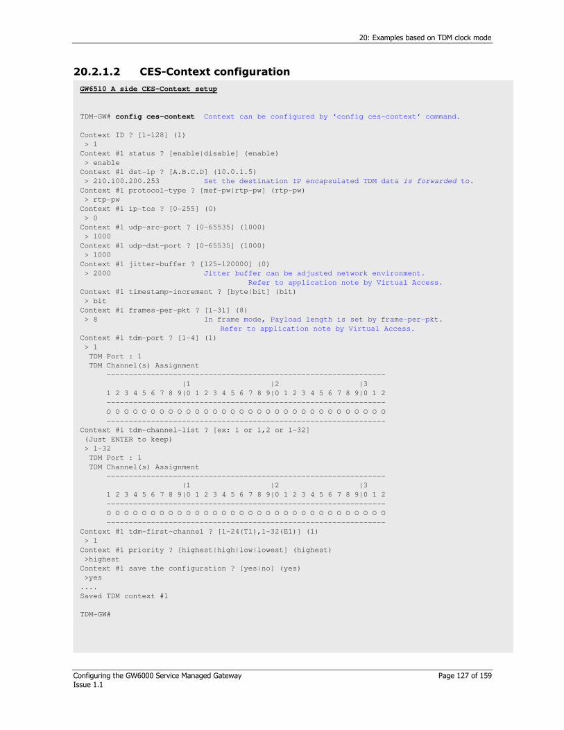
20: Examples based on TDM clock mode
Configuring the GW6000 Service Managed Gateway Page 127 of 159 Issue 1.1
20.2.1.2 CES-Context configuration
GW6510 A side CES-Context setup
TDM-GW# config ces-context Context can be configured by ‘config ces-context’ command.
Context ID ? [1-128] (1)
> 1
Context #1 status ? [enable|disable] (enable)
> enable
Context #1 dst-ip ? [A.B.C.D] (10.0.1.5)
> 210.100.200.253 Set the destination IP encapsulated TDM data is forwarded to.
Context #1 protocol-type ? [mef-pw|rtp-pw] (rtp-pw)
> rtp-pw
Context #1 ip-tos ? [0-255] (0)
> 0
Context #1 udp-src-port ? [0-65535] (1000)
> 1000
Context #1 udp-dst-port ? [0-65535] (1000)
> 1000
Context #1 jitter-buffer ? [125-120000] (0)
> 2000 Jitter buffer can be adjusted network environment.
Refer to application note by Virtual Access.
Context #1 timestamp-increment ? [byte|bit] (bit)
> bit
Context #1 frames-per-pkt ? [1-31] (8)
> 8 In frame mode, Payload length is set by frame-per-pkt.
Refer to application note by Virtual Access.
Context #1 tdm-port ? [1-4] (1)
> 1
TDM Port : 1
TDM Channel(s) Assignment
---------------------------------------------------------------
|1 |2 |3
1 2 3 4 5 6 7 8 9|0 1 2 3 4 5 6 7 8 9|0 1 2 3 4 5 6 7 8 9|0 1 2
---------------------------------------------------------------
O O O O O O O O O O O O O O O O O O O O O O O O O O O O O O O O
---------------------------------------------------------------
Context #1 tdm-channel-list ? [ex: 1 or 1,2 or 1-32]
(Just ENTER to keep)
> 1-32
TDM Port : 1
TDM Channel(s) Assignment
---------------------------------------------------------------
|1 |2 |3
1 2 3 4 5 6 7 8 9|0 1 2 3 4 5 6 7 8 9|0 1 2 3 4 5 6 7 8 9|0 1 2
---------------------------------------------------------------
O O O O O O O O O O O O O O O O O O O O O O O O O O O O O O O O
---------------------------------------------------------------
Context #1 tdm-first-channel ? [1-24(T1),1-32(E1)] (1)
> 1
Context #1 priority ? [highest|high|low|lowest] (highest)
>highest
Context #1 save the configuration ? [yes|no] (yes)
>yes
....
Saved TDM context #1
TDM-GW#
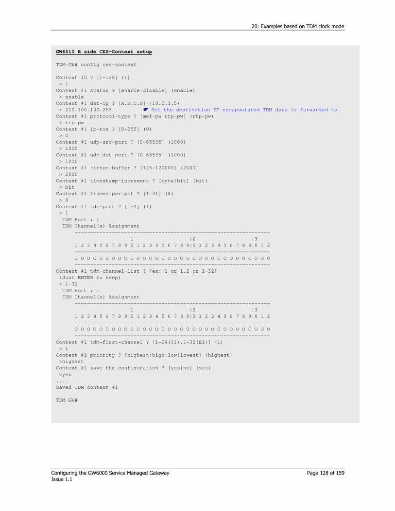
20: Examples based on TDM clock mode
Configuring the GW6000 Service Managed Gateway Page 128 of 159 Issue 1.1
GW6510 B side CES-Context setup
TDM-GW# config ces-context
Context ID ? [1-128] (1)
> 1
Context #1 status ? [enable|disable] (enable)
> enable
Context #1 dst-ip ? [A.B.C.D] (10.0.1.5)
> 210.100.100.253 Set the destination IP encapsulated TDM data is forwarded to.
Context #1 protocol-type ? [mef-pw|rtp-pw] (rtp-pw)
> rtp-pw
Context #1 ip-tos ? [0-255] (0)
> 0
Context #1 udp-src-port ? [0-65535] (1000)
> 1000
Context #1 udp-dst-port ? [0-65535] (1000)
> 1000
Context #1 jitter-buffer ? [125-120000] (2000)
> 2000
Context #1 timestamp-increment ? [byte|bit] (bit)
> bit
Context #1 frames-per-pkt ? [1-31] (8)
> 8
Context #1 tdm-port ? [1-4] (1)
> 1
TDM Port : 1
TDM Channel(s) Assignment
---------------------------------------------------------------
|1 |2 |3
1 2 3 4 5 6 7 8 9|0 1 2 3 4 5 6 7 8 9|0 1 2 3 4 5 6 7 8 9|0 1 2
---------------------------------------------------------------
O O O O O O O O O O O O O O O O O O O O O O O O O O O O O O O O
---------------------------------------------------------------
Context #1 tdm-channel-list ? [ex: 1 or 1,2 or 1-32]
(Just ENTER to keep)
> 1-32
TDM Port : 1
TDM Channel(s) Assignment
---------------------------------------------------------------
|1 |2 |3
1 2 3 4 5 6 7 8 9|0 1 2 3 4 5 6 7 8 9|0 1 2 3 4 5 6 7 8 9|0 1 2
---------------------------------------------------------------
O O O O O O O O O O O O O O O O O O O O O O O O O O O O O O O O
---------------------------------------------------------------
Context #1 tdm-first-channel ? [1-24(T1),1-32(E1)] (1)
> 1
Context #1 priority ? [highest|high|low|lowest] (highest)
>highest
Context #1 save the configuration ? [yes|no] (yes)
>yes
....
Saved TDM context #1
TDM-GW#

20: Examples based on TDM clock mode
Configuring the GW6000 Service Managed Gateway Page 129 of 159 Issue 1.1
20.3 Adaptive -Adaptive clock in frame mode: Case III
Caution!
If uplink 1, 2 are connected to the same segment LAN together, both side (GW6510 and Packet network) should be applied by Spanning Tree Protocol.
Circuit A
Internal clock
Circuit B
From-Rx-clock
GW6510 A: Adaptive-avg-clock
GW6510 B: Adaptive-avg-clock
Packet Network
Figure 46: Network diagram
20.3.1 CLI Configuration
Figure 47: System’s network configuration
GW 6510 A’s system IP address setup
TDM-GW# set system ip 210.100.100.254/16
TDM-GW# set system gateway 210.100.1.1
GW 6510 B’s system IP address setup
TDM-GW# set system ip 210.100.200.254/16
TDM-GW# set system gateway 210.100.1.1
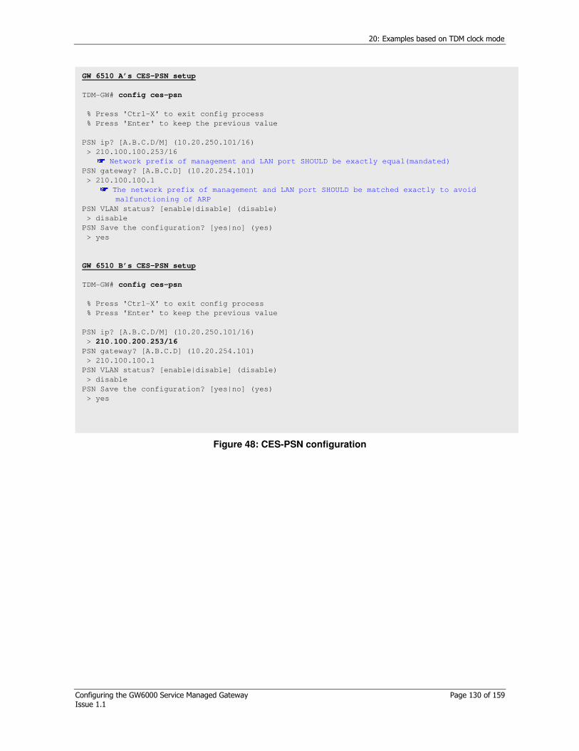
20: Examples based on TDM clock mode
Configuring the GW6000 Service Managed Gateway Page 130 of 159 Issue 1.1
Figure 48: CES-PSN configuration
GW 6510 A’s CES-PSN setup
TDM-GW# config ces-psn
% Press 'Ctrl-X' to exit config process
% Press 'Enter' to keep the previous value
PSN ip? [A.B.C.D/M] (10.20.250.101/16)
> 210.100.100.253/16 Network prefix of management and LAN port SHOULD be exactly equal(mandated)
PSN gateway? [A.B.C.D] (10.20.254.101)
> 210.100.100.1 The network prefix of management and LAN port SHOULD be matched exactly to avoid
malfunctioning of ARP
PSN VLAN status? [enable|disable] (disable)
> disable
PSN Save the configuration? [yes|no] (yes)
> yes
GW 6510 B’s CES-PSN setup
TDM-GW# config ces-psn
% Press 'Ctrl-X' to exit config process
% Press 'Enter' to keep the previous value
PSN ip? [A.B.C.D/M] (10.20.250.101/16)
> 210.100.200.253/16
PSN gateway? [A.B.C.D] (10.20.254.101)
> 210.100.100.1
PSN VLAN status? [enable|disable] (disable)
> disable
PSN Save the configuration? [yes|no] (yes)
> yes
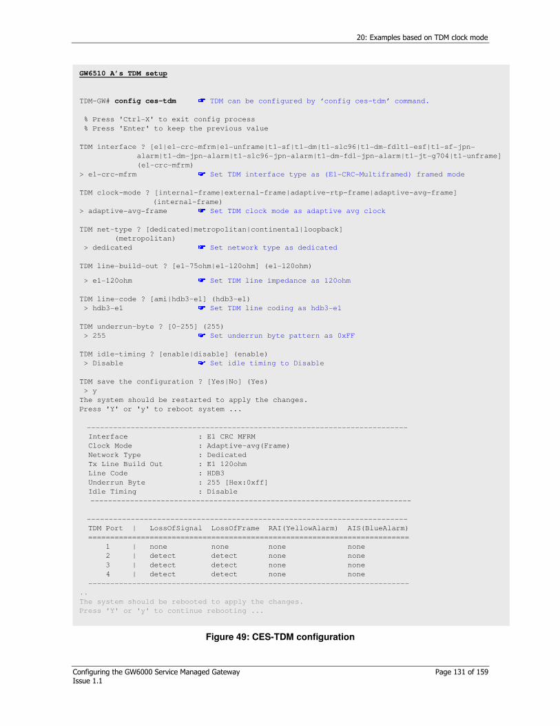
20: Examples based on TDM clock mode
Configuring the GW6000 Service Managed Gateway Page 131 of 159 Issue 1.1
Figure 49: CES-TDM configuration
GW6510 A’s TDM setup
TDM-GW# config ces-tdm TDM can be configured by ‘config ces-tdm’ command.
% Press 'Ctrl-X' to exit config process
% Press 'Enter' to keep the previous value
TDM interface ? [e1|e1-crc-mfrm|e1-unframe|t1-sf|t1-dm|t1-slc96|t1-dm-fdlt1-esf|t1-sf-jpn-
alarm|t1-dm-jpn-alarm|t1-slc96-jpn-alarm|t1-dm-fdl-jpn-alarm|t1-jt-g704|t1-unframe]
(e1-crc-mfrm)
> e1-crc-mfrm Set TDM interface type as (E1-CRC-Multiframed) framed mode
TDM clock-mode ? [internal-frame|external-frame|adaptive-rtp-frame|adaptive-avg-frame]
(internal-frame)
> adaptive-avg-frame Set TDM clock mode as adaptive avg clock
TDM net-type ? [dedicated|metropolitan|continental|loopback]
(metropolitan)
> dedicated Set network type as dedicated
TDM line-build-out ? [e1-75ohm|e1-120ohm] (e1-120ohm)
> e1-120ohm Set TDM line impedance as 120ohm
TDM line-code ? [ami|hdb3-e1] (hdb3-e1)
> hdb3-e1 Set TDM line coding as hdb3-e1
TDM underrun-byte ? [0-255] (255)
> 255 Set underrun byte pattern as 0xFF
TDM idle-timing ? [enable|disable] (enable)
> Disable Set idle timing to Disable
TDM save the configuration ? [Yes|No] (Yes)
> y
The system should be restarted to apply the changes.
Press 'Y' or 'y' to reboot system ...
-------------------------------------------------------------------------
Interface : E1 CRC MFRM
Clock Mode : Adaptive-avg(Frame)
Network Type : Dedicated
Tx Line Build Out : E1 120ohm
Line Code : HDB3
Underrun Byte : 255 [Hex:0xff]
Idle Timing : Disable
-------------------------------------------------------------------------
-------------------------------------------------------------------------
TDM Port | LossOfSignal LossOfFrame RAI(YellowAlarm) AIS(BlueAlarm)
=========================================================================
1 | none none none none
2 | detect detect none none
3 | detect detect none none
4 | detect detect none none
-------------------------------------------------------------------------
..
The system should be rebooted to apply the changes.
Press 'Y' or 'y' to continue rebooting ...
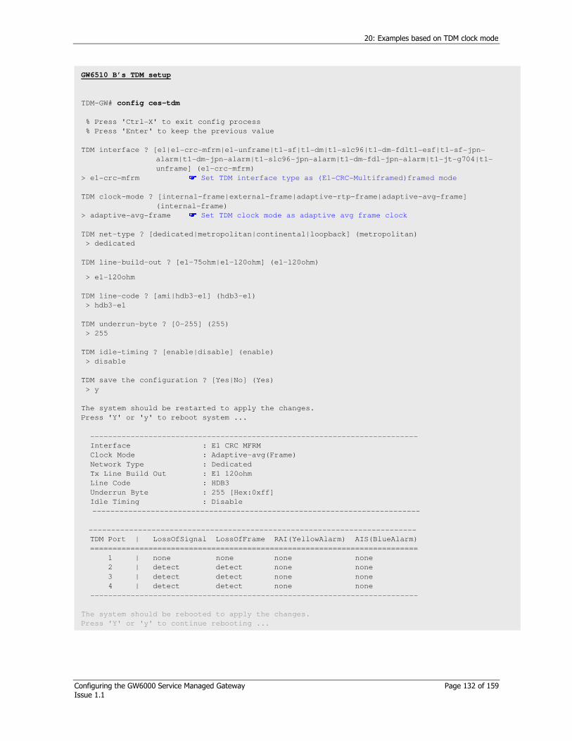
20: Examples based on TDM clock mode
Configuring the GW6000 Service Managed Gateway Page 132 of 159 Issue 1.1
GW6510 B’s TDM setup
TDM-GW# config ces-tdm
% Press 'Ctrl-X' to exit config process
% Press 'Enter' to keep the previous value
TDM interface ? [e1|e1-crc-mfrm|e1-unframe|t1-sf|t1-dm|t1-slc96|t1-dm-fdlt1-esf|t1-sf-jpn-
alarm|t1-dm-jpn-alarm|t1-slc96-jpn-alarm|t1-dm-fdl-jpn-alarm|t1-jt-g704|t1-
unframe] (e1-crc-mfrm)
> e1-crc-mfrm Set TDM interface type as (E1-CRC-Multiframed)framed mode
TDM clock-mode ? [internal-frame|external-frame|adaptive-rtp-frame|adaptive-avg-frame]
(internal-frame)
> adaptive-avg-frame Set TDM clock mode as adaptive avg frame clock
TDM net-type ? [dedicated|metropolitan|continental|loopback] (metropolitan)
> dedicated
TDM line-build-out ? [e1-75ohm|e1-120ohm] (e1-120ohm)
> e1-120ohm
TDM line-code ? [ami|hdb3-e1] (hdb3-e1)
> hdb3-e1
TDM underrun-byte ? [0-255] (255)
> 255
TDM idle-timing ? [enable|disable] (enable)
> disable
TDM save the configuration ? [Yes|No] (Yes)
> y
The system should be restarted to apply the changes.
Press 'Y' or 'y' to reboot system ...
-------------------------------------------------------------------------
Interface : E1 CRC MFRM
Clock Mode : Adaptive-avg(Frame)
Network Type : Dedicated
Tx Line Build Out : E1 120ohm
Line Code : HDB3
Underrun Byte : 255 [Hex:0xff]
Idle Timing : Disable
-------------------------------------------------------------------------
-------------------------------------------------------------------------
TDM Port | LossOfSignal LossOfFrame RAI(YellowAlarm) AIS(BlueAlarm)
=========================================================================
1 | none none none none
2 | detect detect none none
3 | detect detect none none
4 | detect detect none none
-------------------------------------------------------------------------
The system should be rebooted to apply the changes.
Press 'Y' or 'y' to continue rebooting ...

20: Examples based on TDM clock mode
Configuring the GW6000 Service Managed Gateway Page 133 of 159 Issue 1.1
Figure 50: CES-Context configuration
GW6510 A side CES-Context setup
TDM-GW# config ces-context Context can be configured by ‘config ces-context’ command.
Context ID ? [1-128] (1)
> 1
Context #1 status ? [enable|disable] (enable)
> enable
Context #1 dst-ip ? [A.B.C.D] (10.0.1.5)
> 210.100.200.253 Set the destination IP encapsulated TDM data is forwarded to.
Context #1 protocol-type ? [mef-pw|rtp-pw] (rtp-pw)
> rtp-pw
Context #1 ip-tos ? [0-255] (0)
> 0
Context #1 udp-src-port ? [0-65535] (1000)
> 1000
Context #1 udp-dst-port ? [0-65535] (1000)
> 1000
Context #1 jitter-buffer ? [125-120000] (0)
> 2000 Jitter buffer can be adjusted network environment.
Refer to application note by Virtual Access.
Context #1 timestamp-increment ? [byte|bit] (bit)
> bit
Context #1 frames-per-pkt ? [1-31] (8)
> 8 In frame mode, Payload length is set by frame-per-pkt. Refer to application note by Virtual Access.
Context #1 tdm-port ? [1-4] (1)
> 1
TDM Port : 1
TDM Channel(s) Assignment
---------------------------------------------------------------
|1 |2 |3
1 2 3 4 5 6 7 8 9|0 1 2 3 4 5 6 7 8 9|0 1 2 3 4 5 6 7 8 9|0 1 2
---------------------------------------------------------------
O O O O O O O O O O O O O O O O O O O O O O O O O O O O O O O O
---------------------------------------------------------------
Context #1 tdm-channel-list ? [ex: 1 or 1,2 or 1-32]
(Just ENTER to keep)
> 1-32
TDM Port : 1
TDM Channel(s) Assignment
---------------------------------------------------------------
|1 |2 |3
1 2 3 4 5 6 7 8 9|0 1 2 3 4 5 6 7 8 9|0 1 2 3 4 5 6 7 8 9|0 1 2
---------------------------------------------------------------
O O O O O O O O O O O O O O O O O O O O O O O O O O O O O O O O
---------------------------------------------------------------
Context #1 tdm-first-channel ? [1-24(T1),1-32(E1)] (1)
> 1
Context #1 priority ? [highest|high|low|lowest] (highest)
>highest
Context #1 save the configuration ? [yes|no] (yes)
>yes
....
Saved TDM context #1
TDM-GW#
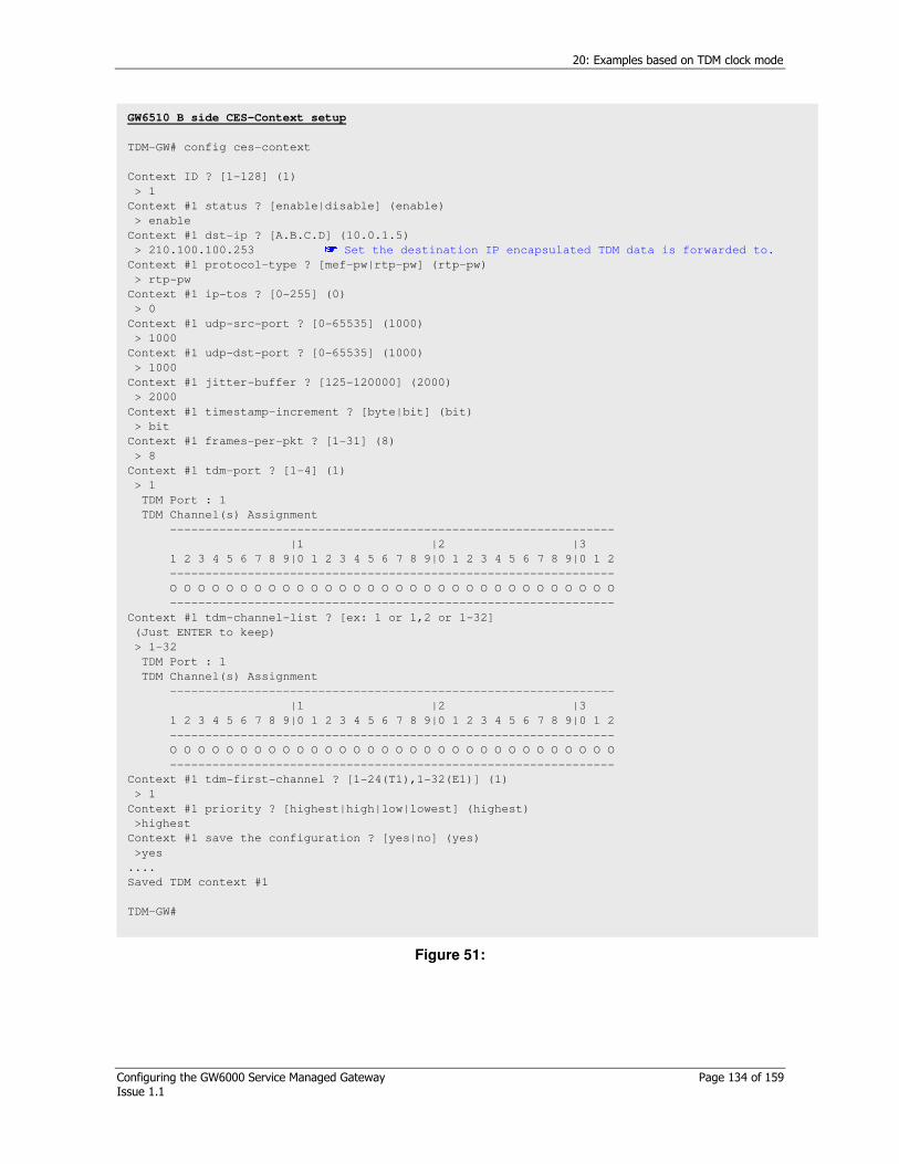
20: Examples based on TDM clock mode
Configuring the GW6000 Service Managed Gateway Page 134 of 159 Issue 1.1
Figure 51:
GW6510 B side CES-Context setup
TDM-GW# config ces-context
Context ID ? [1-128] (1)
> 1
Context #1 status ? [enable|disable] (enable)
> enable
Context #1 dst-ip ? [A.B.C.D] (10.0.1.5)
> 210.100.100.253 Set the destination IP encapsulated TDM data is forwarded to.
Context #1 protocol-type ? [mef-pw|rtp-pw] (rtp-pw)
> rtp-pw
Context #1 ip-tos ? [0-255] (0)
> 0
Context #1 udp-src-port ? [0-65535] (1000)
> 1000
Context #1 udp-dst-port ? [0-65535] (1000)
> 1000
Context #1 jitter-buffer ? [125-120000] (2000)
> 2000
Context #1 timestamp-increment ? [byte|bit] (bit)
> bit
Context #1 frames-per-pkt ? [1-31] (8)
> 8
Context #1 tdm-port ? [1-4] (1)
> 1
TDM Port : 1
TDM Channel(s) Assignment
---------------------------------------------------------------
|1 |2 |3
1 2 3 4 5 6 7 8 9|0 1 2 3 4 5 6 7 8 9|0 1 2 3 4 5 6 7 8 9|0 1 2
---------------------------------------------------------------
O O O O O O O O O O O O O O O O O O O O O O O O O O O O O O O O
---------------------------------------------------------------
Context #1 tdm-channel-list ? [ex: 1 or 1,2 or 1-32]
(Just ENTER to keep)
> 1-32
TDM Port : 1
TDM Channel(s) Assignment
---------------------------------------------------------------
|1 |2 |3
1 2 3 4 5 6 7 8 9|0 1 2 3 4 5 6 7 8 9|0 1 2 3 4 5 6 7 8 9|0 1 2
---------------------------------------------------------------
O O O O O O O O O O O O O O O O O O O O O O O O O O O O O O O O
---------------------------------------------------------------
Context #1 tdm-first-channel ? [1-24(T1),1-32(E1)] (1)
> 1
Context #1 priority ? [highest|high|low|lowest] (highest)
>highest
Context #1 save the configuration ? [yes|no] (yes)
>yes
....
Saved TDM context #1
TDM-GW#

20: Examples based on TDM clock mode
Configuring the GW6000 Service Managed Gateway Page 135 of 159 Issue 1.1
20.4 Loopback-Adaptive clock in unframe mode: Case IV
Caution! If uplink 1,2 are connected to the same segment LAN together, both side (GW6510 and Packet network) should be applied by Spanning Tree Protocol.
Circuit A
Internal clock
Circuit B From-Rx-clock
GW6510 A: Loopback
GW6510 B: Adaptive-avg-clock
Packet Network
Figure 52: Network diagram
20.4.1 CLI Configuration
20.4.1.1 System network configuration
Figure 53: System network configuration
GW6510 A’s system IP address setup
TDM-GW# set system ip 210.100.100.254/16
TDM-GW# set system gateway 210.100.1.1
GW6510 B’s system IP address setup
TDM-GW# set system ip 210.100.200.254/16
TDM-GW# set system gateway 210.100.1.1

20: Examples based on TDM clock mode
Configuring the GW6000 Service Managed Gateway Page 136 of 159 Issue 1.1
Figure 54:
GW6510 A’s CES-PSN setup
TDM-GW# config ces-psn
% Press 'Ctrl-X' to exit config process
% Press 'Enter' to keep the previous value
PSN ip? [A.B.C.D/M] (10.20.250.101/16)
> 210.100.100.253/16 Network prefix of management and LAN port SHOULD be exactly equal(mandated)
PSN gateway? [A.B.C.D] (10.20.254.101)
> 210.100.100.1 The network prefix of management and LAN port SHOULD be matched exactly to avoid
malfunctioning of ARP
PSN VLAN status? [enable|disable] (disable)
> disable
PSN Save the configuration? [yes|no] (yes)
> yes
GW6510 B’s CES-PSN setup
TDM-GW# config ces-psn
% Press 'Ctrl-X' to exit config process
% Press 'Enter' to keep the previous value
PSN ip? [A.B.C.D/M] (10.20.250.101/16)
> 210.100.200.253/16
PSN gateway? [A.B.C.D] (10.20.254.101)
> 210.100.100.1
PSN VLAN status? [enable|disable] (disable)
> disable
PSN Save the configuration? [yes|no] (yes)
> yes
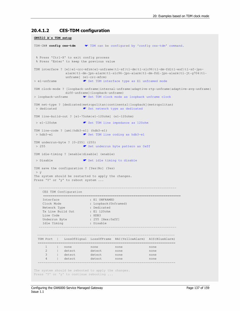
20: Examples based on TDM clock mode
Configuring the GW6000 Service Managed Gateway Page 137 of 159 Issue 1.1
20.4.1.2 CES-TDM configuration
GW6510 A’s TDM setup
TDM-GW# config ces-tdm TDM can be configured by ‘config ces-tdm’ command.
% Press 'Ctrl-X' to exit config process
% Press 'Enter' to keep the previous value
TDM interface ? [e1|e1-crc-mfrm|e1-unframe|t1-sf|t1-dm|t1-slc96|t1-dm-fdlt1-esf|t1-sf-jpn-
alarm|t1-dm-jpn-alarm|t1-slc96-jpn-alarm|t1-dm-fdl-jpn-alarm|t1-jt-g704|t1-
unframe] (e1-crc-mfrm)
> e1-unframe Set TDM interface type as E1 unframed mode
TDM clock-mode ? [loopback-unframe|internal-unframe|adaptive-rtp-unframe|adaptive-avg-unframe|
diff-unframe](loopback-unframe)
> loopback-unframe Set TDM clock mode as loopback unframe clock
TDM net-type ? [dedicated|metropolitan|continental|loopback](metropolitan)
> dedicated Set network type as dedicated
TDM line-build-out ? [e1-75ohm|e1-120ohm] (e1-120ohm)
> e1-120ohm Set TDM line impedance as 120ohm
TDM line-code ? [ami|hdb3-e1] (hdb3-e1)
> hdb3-e1 Set TDM line coding as hdb3-e1
TDM underrun-byte ? [0-255] (255)
> 255 Set underrun byte pattern as 0xff
TDM idle-timing ? [enable|disable] (enable)
> Disable Set idle timing to disable
TDM save the configuration ? [Yes|No] (Yes)
> y
The system should be restarted to apply the changes.
Press 'Y' or 'y' to reboot system ...
-------------------------------------------------------------------------
CES TDM Configuration
=========================================================================
Interface : E1 UNFRAMED
Clock Mode : Loopback(Unframed)
Network Type : Dedicated
Tx Line Build Out : E1 120ohm
Line Code : HDB3
Underrun Byte : 255 [Hex:0xff]
Idle Timing : Disable
-------------------------------------------------------------------------
-------------------------------------------------------------------------
TDM Port | LossOfSignal LossOfFrame RAI(YellowAlarm) AIS(BlueAlarm)
=========================================================================
1 | none none none none
2 | detect detect none none
3 | detect detect none none
4 | detect detect none none
-------------------------------------------------------------------------
The system should be rebooted to apply the changes.
Press 'Y' or 'y' to continue rebooting ...

20: Examples based on TDM clock mode
Configuring the GW6000 Service Managed Gateway Page 138 of 159 Issue 1.1
Figure 55:
GW6510 A’s TDM setup
TDM-GW# config ces-tdm TDM can be configured by ‘config ces-tdm’ command.
% Press 'Ctrl-X' to exit config process
% Press 'Enter' to keep the previous value
TDM interface ? [e1|e1-crc-mfrm|e1-unframe|t1-sf|t1-dm|t1-slc96|t1-dm-fdlt1-esf|t1-sf-jpn-
alarm|t1-dm-jpn-alarm|t1-slc96-jpn-alarm|t1-dm-fdl-jpn-alarm|t1-jt-g704|t1-
unframe] (e1-crc-mfrm)
> e1-unframe Set TDM interface type as E1 unframed mode
TDM clock-mode ? [loopback-unframe|internal-unframe|adaptive-rtp-unframe|adaptive-avg-unframe|
diff-unframe](loopback-unframe)
> loopback-unframe Set TDM clock mode as loopback unframe clock
TDM net-type ? [dedicated|metropolitan|continental|loopback](metropolitan)
> dedicated Set network type as dedicated
TDM line-build-out ? [e1-75ohm|e1-120ohm] (e1-120ohm)
> e1-120ohm Set TDM line impedance as 120ohm
TDM line-code ? [ami|hdb3-e1] (hdb3-e1)
> hdb3-e1 Set TDM line coding as hdb3-e1
TDM underrun-byte ? [0-255] (255)
> 255 Set underrun byte pattern as 0xff
TDM idle-timing ? [enable|disable] (enable)
> Disable Set idle timing to disable
TDM save the configuration ? [Yes|No] (Yes)
> y
The system should be restarted to apply the changes.
Press 'Y' or 'y' to reboot system ...
-------------------------------------------------------------------------
CES TDM Configuration
=========================================================================
Interface : E1 UNFRAMED
Clock Mode : Loopback(Unframed)
Network Type : Dedicated
Tx Line Build Out : E1 120ohm
Line Code : HDB3
Underrun Byte : 255 [Hex:0xff]
Idle Timing : Disable
-------------------------------------------------------------------------
-------------------------------------------------------------------------
TDM Port | LossOfSignal LossOfFrame RAI(YellowAlarm) AIS(BlueAlarm)
=========================================================================
1 | none none none none
2 | detect detect none none
3 | detect detect none none
4 | detect detect none none
-------------------------------------------------------------------------
The system should be rebooted to apply the changes.
Press 'Y' or 'y' to continue rebooting ...

20: Examples based on TDM clock mode
Configuring the GW6000 Service Managed Gateway Page 139 of 159 Issue 1.1
20.4.1.3 CES context set up
Figure 56:
GW6510 A side CES-Context setup
TDM-GW# config ces-context Context can be configured by ‘config ces-context’ command.
Context ID ? [1-4] (1)
> 1
Context #1 status ? [enable|disable] (enable)
> enable
Context #1 dst-ip ? [A.B.C.D] (10.0.1.5)
> 210.100.200.253 Set the destination IP encapsulated TDM data is forwarded to.
Context #1 protocol-type ? [mef-pw|rtp-pw] (rtp-pw)
> rtp-pw
Context #1 ip-tos ? [0-255] (0)
> 0
Context #1 udp-src-port ? [0-65535] (1000)
> 1000
Context #1 udp-dst-port ? [0-65535] (1000)
> 1000
Context #1 jitter-buffer ? [125-120000] (0)
> 2000 Jitter buffer can be adjusted network environment.
Refer to application note by comtec.
Context #1 timestamp-increment ? [byte|bit] (bit)
> bit
Context #1 bytes-per-pkt ? [1-1023] (8)
> 8 In unframed mode, Payload length is set by bytes-per-pkt. Refer to application note by comtec.
Context #1 priority ? [highest|high|low|lowest] (highest)
>highest
Context #1 save the configuration ? [yes|no] (yes)
>yes
....
Saved TDM context #1
TDM-GW#

20: Examples based on TDM clock mode
Configuring the GW6000 Service Managed Gateway Page 140 of 159 Issue 1.1
20.5 Internal-Adaptive avg clock in unframe mode: Case V
Caution! If uplink 1,2 are connected to the same segment LAN together, both side (GW6510 and Packet network) should be applied by Spanning Tree Protocol.
Circuit A
From Rx clock
Circuit B From-Rx-clock
GW6510 A: Internal clock
GW6510 B: Adaptive-avg-clock
Packet Network
Figure 57: Network diagram

20: Examples based on TDM clock mode
Configuring the GW6000 Service Managed Gateway Page 141 of 159 Issue 1.1
Figure 58: CES-context setup
GW6510 B side CES-Context setup
GW6000# config ces-context Context can be configured by ‘config ces-context’ command.
Context ID ? [1-4] (1)
> 1
Context #1 status ? [enable|disable] (enable)
> enable
Context #1 dst-ip ? [A.B.C.D] (10.0.1.5)
> 210.100.100.253 Set the destination IP encapsulated TDM data is forwarded to.
Context #1 protocol-type ? [mef-pw|rtp-pw] (rtp-pw)
> rtp-pw
Context #1 ip-tos ? [0-255] (0)
> 0
Context #1 udp-src-port ? [0-65535] (1000)
> 1000
Context #1 udp-dst-port ? [0-65535] (1000)
> 1000
Context #1 jitter-buffer ? [125-120000] (0)
> 2000 Jitter buffer can be adjusted network environment.
Refer to application notes by Virtual Access.
Context #1 timestamp-increment ? [byte|bit] (bit)
> bit
Context #1 bytes-per-pkt ? [1-1023] (8)
> 8 In unframed mode, Payload length is set by bytes-per-pkt. Refer to application notes by Virtual Access..
Context #1 priority ? [highest|high|low|lowest] (highest)
>highest
Context #1 save the configuration ? [yes|no] (yes)
>yes
....
Saved TDM context #1
TDM-GW#
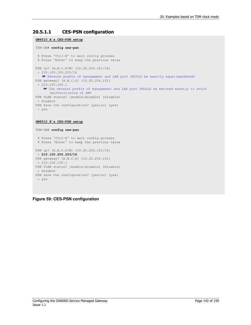
20: Examples based on TDM clock mode
Configuring the GW6000 Service Managed Gateway Page 142 of 159 Issue 1.1
20.5.1.1 CES-PSN configuration
Figure 59: CES-PSN configuration
GW6510 A’s CES-PSN setup
TDM-GW# config ces-psn
% Press 'Ctrl-X' to exit config process
% Press 'Enter' to keep the previous value
PSN ip? [A.B.C.D/M] (10.20.250.101/16)
> 210.100.100.253/16 Network prefix of management and LAN port SHOULD be exactly equal(mandated)
PSN gateway? [A.B.C.D] (10.20.254.101)
> 210.100.100.1 The network prefix of management and LAN port SHOULD be matched exactly to avoid
malfunctioning of ARP
PSN VLAN status? [enable|disable] (disable)
> disable
PSN Save the configuration? [yes|no] (yes)
> yes
GW6510 B’s CES-PSN setup
TDM-GW# config ces-psn
% Press 'Ctrl-X' to exit config process
% Press 'Enter' to keep the previous value
PSN ip? [A.B.C.D/M] (10.20.250.101/16)
> 210.100.200.253/16
PSN gateway? [A.B.C.D] (10.20.254.101)
> 210.100.100.1
PSN VLAN status? [enable|disable] (disable)
> disable
PSN Save the configuration? [yes|no] (yes)
> yes
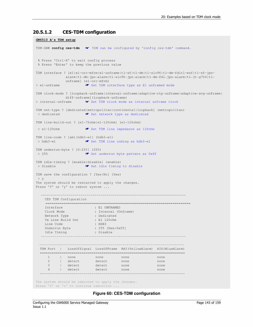
20: Examples based on TDM clock mode
Configuring the GW6000 Service Managed Gateway Page 143 of 159 Issue 1.1
20.5.1.2 CES-TDM configuration
Figure 60: CES-TDM configuration
GW6510 A’s TDM setup
TDM-GW# config ces-tdm TDM can be configured by ‘config ces-tdm’ command.
% Press 'Ctrl-X' to exit config process
% Press 'Enter' to keep the previous value
TDM interface ? [e1|e1-crc-mfrm|e1-unframe|t1-sf|t1-dm|t1-slc96|t1-dm-fdlt1-esf|t1-sf-jpn-
alarm|t1-dm-jpn-alarm|t1-slc96-jpn-alarm|t1-dm-fdl-jpn-alarm|t1-jt-g704|t1-
unframe] (e1-crc-mfrm)
> e1-unframe Set TDM interface type as E1 unframed mode
TDM clock-mode ? [loopback-unframe|internal-unframe|adaptive-rtp-unframe|adaptive-avg-unframe|
diff-unframe](loopback-unframe)
> internal-unframe Set TDM clock mode as internal unframe clock
TDM net-type ? [dedicated|metropolitan|continental|loopback] (metropolitan)
> dedicated Set network type as dedicated
TDM line-build-out ? [e1-75ohm|e1-120ohm] (e1-120ohm)
> e1-120ohm Set TDM line impedance as 120ohm
TDM line-code ? [ami|hdb3-e1] (hdb3-e1)
> hdb3-e1 Set TDM line coding as hdb3-e1
TDM underrun-byte ? [0-255] (255)
> 255 Set underrun byte pattern as 0xff
TDM idle-timing ? [enable|disable] (enable)
> Disable Set idle timing to disable
TDM save the configuration ? [Yes|No] (Yes)
> y
The system should be restarted to apply the changes.
Press 'Y' or 'y' to reboot system ...
-------------------------------------------------------------------------
CES TDM Configuration
=========================================================================
Interface : E1 UNFRAMED
Clock Mode : Internal (Unframe)
Network Type : Dedicated
Tx Line Build Out : E1 120ohm
Line Code : HDB3
Underrun Byte : 255 [Hex:0xff]
Idle Timing : Disable
-------------------------------------------------------------------------
-------------------------------------------------------------------------
TDM Port | LossOfSignal LossOfFrame RAI(YellowAlarm) AIS(BlueAlarm)
=========================================================================
1 | none none none none
2 | detect detect none none
3 | detect detect none none
4 | detect detect none none
-------------------------------------------------------------------------
The system should be rebooted to apply the changes.
Press 'Y' or 'y' to continue rebooting ...
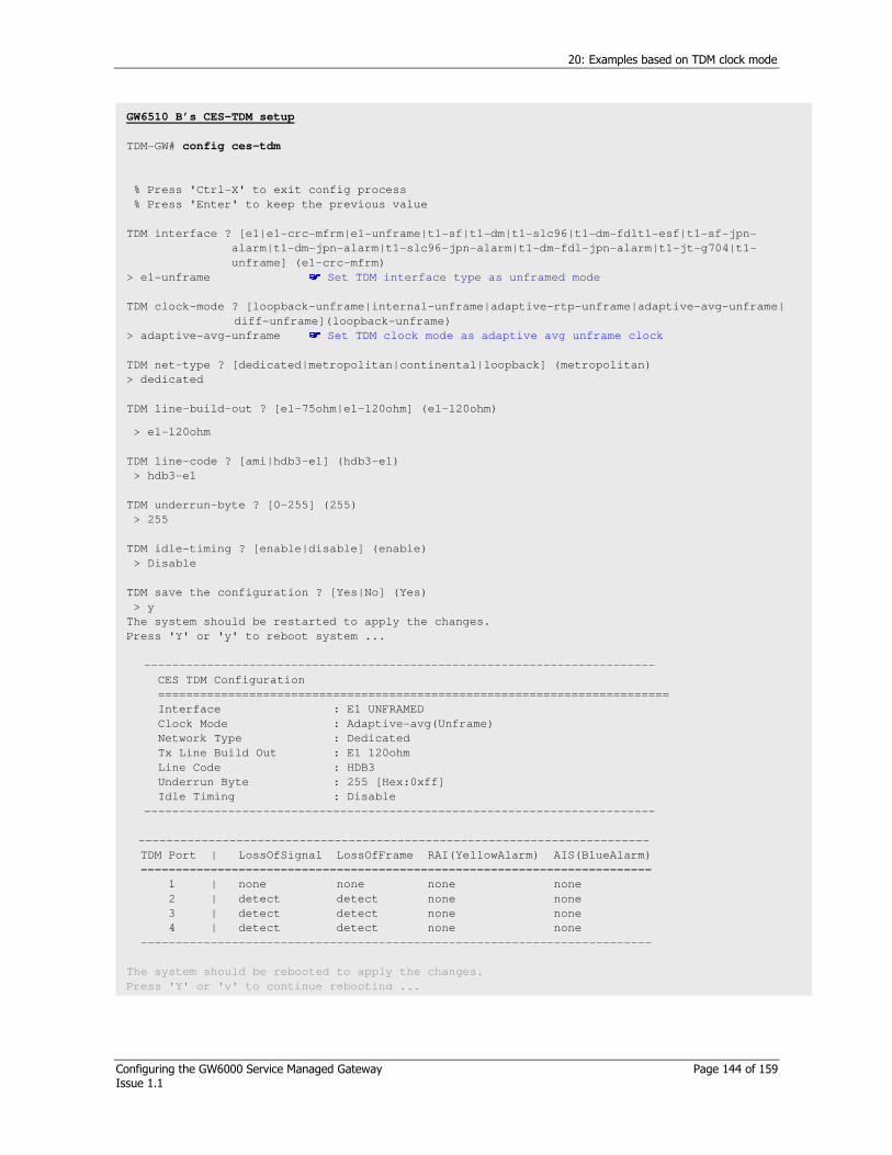
20: Examples based on TDM clock mode
Configuring the GW6000 Service Managed Gateway Page 144 of 159 Issue 1.1
GW6510 B’s CES-TDM setup
TDM-GW# config ces-tdm
% Press 'Ctrl-X' to exit config process
% Press 'Enter' to keep the previous value
TDM interface ? [e1|e1-crc-mfrm|e1-unframe|t1-sf|t1-dm|t1-slc96|t1-dm-fdlt1-esf|t1-sf-jpn-
alarm|t1-dm-jpn-alarm|t1-slc96-jpn-alarm|t1-dm-fdl-jpn-alarm|t1-jt-g704|t1-
unframe] (e1-crc-mfrm)
> e1-unframe Set TDM interface type as unframed mode
TDM clock-mode ? [loopback-unframe|internal-unframe|adaptive-rtp-unframe|adaptive-avg-unframe|
diff-unframe](loopback-unframe)
> adaptive-avg-unframe Set TDM clock mode as adaptive avg unframe clock
TDM net-type ? [dedicated|metropolitan|continental|loopback] (metropolitan)
> dedicated
TDM line-build-out ? [e1-75ohm|e1-120ohm] (e1-120ohm)
> e1-120ohm
TDM line-code ? [ami|hdb3-e1] (hdb3-e1)
> hdb3-e1
TDM underrun-byte ? [0-255] (255)
> 255
TDM idle-timing ? [enable|disable] (enable)
> Disable
TDM save the configuration ? [Yes|No] (Yes)
> y
The system should be restarted to apply the changes.
Press 'Y' or 'y' to reboot system ...
-------------------------------------------------------------------------
CES TDM Configuration
=========================================================================
Interface : E1 UNFRAMED
Clock Mode : Adaptive-avg(Unframe)
Network Type : Dedicated
Tx Line Build Out : E1 120ohm
Line Code : HDB3
Underrun Byte : 255 [Hex:0xff]
Idle Timing : Disable
-------------------------------------------------------------------------
-------------------------------------------------------------------------
TDM Port | LossOfSignal LossOfFrame RAI(YellowAlarm) AIS(BlueAlarm)
=========================================================================
1 | none none none none
2 | detect detect none none
3 | detect detect none none
4 | detect detect none none
-------------------------------------------------------------------------
The system should be rebooted to apply the changes.
Press 'Y' or 'y' to continue rebooting ...
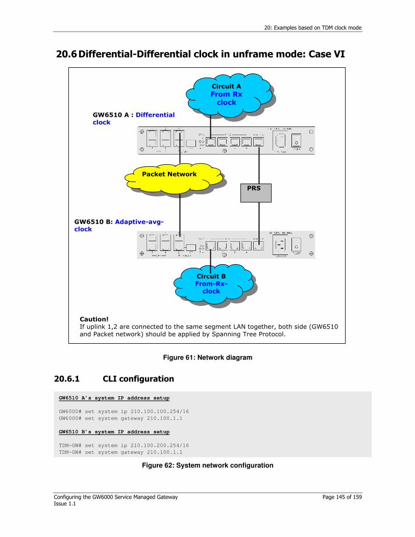
20: Examples based on TDM clock mode
Configuring the GW6000 Service Managed Gateway Page 145 of 159 Issue 1.1
20.6 Differential-Differential clock in unframe mode: Case VI
Caution! If uplink 1,2 are connected to the same segment LAN together, both side (GW6510 and Packet network) should be applied by Spanning Tree Protocol.
Circuit A
From Rx clock
Circuit B From-Rx-clock
GW6510 A : Differential clock
GW6510 B: Adaptive-avg-clock
Packet Network
PRS
Figure 61: Network diagram
20.6.1 CLI configuration
Figure 62: System network configuration
GW6510 A’s system IP address setup
GW6000# set system ip 210.100.100.254/16
GW6000# set system gateway 210.100.1.1
GW6510 B’s system IP address setup
TDM-GW# set system ip 210.100.200.254/16
TDM-GW# set system gateway 210.100.1.1

20: Examples based on TDM clock mode
Configuring the GW6000 Service Managed Gateway Page 146 of 159 Issue 1.1
Figure 63: CES-PSN configuration
GW6510 A’s CES-PSN setup
GW6000# config ces-psn
% Press 'Ctrl-X' to exit config process
% Press 'Enter' to keep the previous value
PSN ip? [A.B.C.D/M] (10.20.250.101/16)
> 210.100.100.253/16 Network prefix of management and LAN port SHOULD be exactly equal(mandated)
PSN gateway? [A.B.C.D] (10.20.254.101)
> 210.100.100.1 The network prefix of management and LAN port SHOULD be matched exactly to avoid
malfunctioning of ARP
PSN VLAN status? [enable|disable] (disable)
> disable
PSN Save the configuration? [yes|no] (yes)
> yes
GW6510 B’s CES-PSN setup
TDM-GW# config ces-psn
% Press 'Ctrl-X' to exit config process
% Press 'Enter' to keep the previous value
PSN ip? [A.B.C.D/M] (10.20.250.101/16)
> 210.100.200.253/16
PSN gateway? [A.B.C.D] (10.20.254.101)
> 210.100.100.1
PSN VLAN status? [enable|disable] (disable)
> disable
PSN Save the configuration? [yes|no] (yes)
> yes
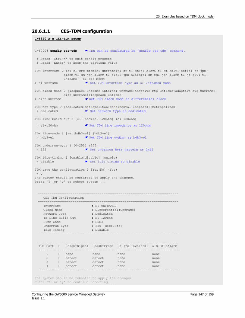
20: Examples based on TDM clock mode
Configuring the GW6000 Service Managed Gateway Page 147 of 159 Issue 1.1
20.6.1.1 CES-TDM configuration
GW6510 A’s CES-TDM setup
GW6000# config ces-tdm TDM can be configured be ‘config ces-tdm’ command.
% Press 'Ctrl-X' to exit config process
% Press 'Enter' to keep the previous value
TDM interface ? [e1|e1-crc-mfrm|e1-unframe|t1-sf|t1-dm|t1-slc96|t1-dm-fdlt1-esf|t1-sf-jpn-
alarm|t1-dm-jpn-alarm|t1-slc96-jpn-alarm|t1-dm-fdl-jpn-alarm|t1-jt-g704|t1-
unframe] (e1-crc-mfrm)
> e1-unframe Set TDM interface type as E1 unframed mode
TDM clock-mode ? [loopback-unframe|internal-unframe|adaptive-rtp-unframe|adaptive-avg-unframe|
diff-unframe](loopback-unframe)
> diff-unframe Set TDM clock mode as differential clock
TDM net-type ? [dedicated|metropolitan|continental|loopback](metropolitan)
> dedicated Set network type as dedicated
TDM line-build-out ? [e1-75ohm|e1-120ohm] (e1-120ohm)
> e1-120ohm Set TDM line impedance as 120ohm
TDM line-code ? [ami|hdb3-e1] (hdb3-e1)
> hdb3-e1 Set TDM line coding as hdb3-e1
TDM underrun-byte ? [0-255] (255)
> 255 Set underrun byte pattern as 0xff
TDM idle-timing ? [enable|disable] (enable)
> disable Set idle timing to disable
TDM save the configuration ? [Yes|No] (Yes)
> y
The system should be restarted to apply the changes.
Press 'Y' or 'y' to reboot system ...
-------------------------------------------------------------------------
CES TDM Configuration
=========================================================================
Interface : E1 UNFRAMED
Clock Mode : Differential(Unframe)
Network Type : Dedicated
Tx Line Build Out : E1 120ohm
Line Code : HDB3
Underrun Byte : 255 [Hex:0xff]
Idle Timing : Disable
-------------------------------------------------------------------------
-------------------------------------------------------------------------
TDM Port | LossOfSignal LossOfFrame RAI(YellowAlarm) AIS(BlueAlarm)
=========================================================================
1 | none none none none
2 | detect detect none none
3 | detect detect none none
4 | detect detect none none
-------------------------------------------------------------------------
The system should be rebooted to apply the changes.
Press 'Y' or 'y' to continue rebooting ...
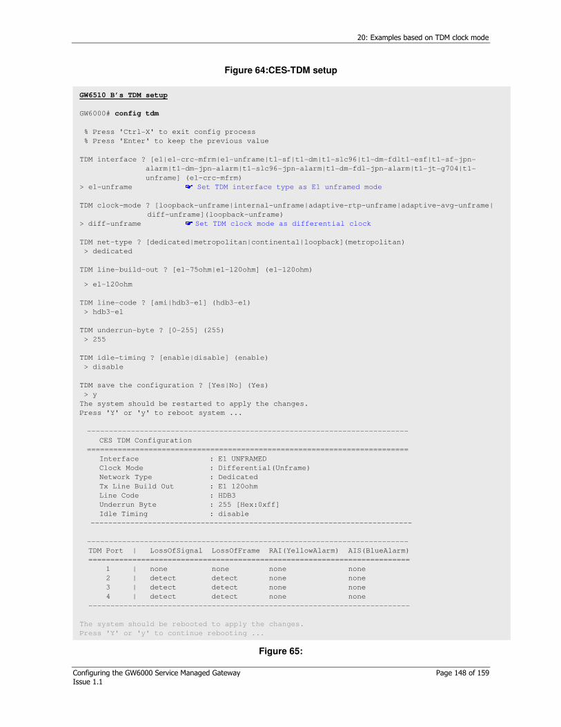
20: Examples based on TDM clock mode
Configuring the GW6000 Service Managed Gateway Page 148 of 159 Issue 1.1
Figure 64:CES-TDM setup
Figure 65:
GW6510 B’s TDM setup
GW6000# config tdm
% Press 'Ctrl-X' to exit config process
% Press 'Enter' to keep the previous value
TDM interface ? [e1|e1-crc-mfrm|e1-unframe|t1-sf|t1-dm|t1-slc96|t1-dm-fdlt1-esf|t1-sf-jpn-
alarm|t1-dm-jpn-alarm|t1-slc96-jpn-alarm|t1-dm-fdl-jpn-alarm|t1-jt-g704|t1-
unframe] (e1-crc-mfrm)
> e1-unframe Set TDM interface type as E1 unframed mode
TDM clock-mode ? [loopback-unframe|internal-unframe|adaptive-rtp-unframe|adaptive-avg-unframe|
diff-unframe](loopback-unframe)
> diff-unframe Set TDM clock mode as differential clock
TDM net-type ? [dedicated|metropolitan|continental|loopback](metropolitan)
> dedicated
TDM line-build-out ? [e1-75ohm|e1-120ohm] (e1-120ohm)
> e1-120ohm
TDM line-code ? [ami|hdb3-e1] (hdb3-e1)
> hdb3-e1
TDM underrun-byte ? [0-255] (255)
> 255
TDM idle-timing ? [enable|disable] (enable)
> disable
TDM save the configuration ? [Yes|No] (Yes)
> y
The system should be restarted to apply the changes.
Press 'Y' or 'y' to reboot system ...
-------------------------------------------------------------------------
CES TDM Configuration
=========================================================================
Interface : E1 UNFRAMED
Clock Mode : Differential(Unframe)
Network Type : Dedicated
Tx Line Build Out : E1 120ohm
Line Code : HDB3
Underrun Byte : 255 [Hex:0xff]
Idle Timing : disable
-------------------------------------------------------------------------
-------------------------------------------------------------------------
TDM Port | LossOfSignal LossOfFrame RAI(YellowAlarm) AIS(BlueAlarm)
=========================================================================
1 | none none none none
2 | detect detect none none
3 | detect detect none none
4 | detect detect none none
-------------------------------------------------------------------------
The system should be rebooted to apply the changes.
Press 'Y' or 'y' to continue rebooting ...
20: Examples based on TDM clock mode
Configuring the GW6000 Service Managed Gateway Page 149 of 159 Issue 1.1
20.6.1.2 CES context setup
Figure 66: CES context setup
GW6510 A side CES-Context setup
GW6000# config ces-context Context can be configured by ‘config ces-context’ command.
Context ID ? [1-4] (1)
> 1
Context #1 status ? [enable|disable] (enable)
> enable
Context #1 dst-ip ? [A.B.C.D] (10.0.1.5)
> 210.100.200.253 Set the destination IP encapsulated TDM data is forwarded to.
Context #1 protocol-type ? [mef-pw|rtp-pw] (rtp-pw)
> rtp-pw
Context #1 ip-tos ? [0-255] (0)
> 0
Context #1 udp-src-port ? [0-65535] (1000)
> 1000
Context #1 udp-dst-port ? [0-65535] (1000)
> 1000
Context #1 jitter-buffer ? [125-120000] (0)
> 2000 Jitter buffer can be adjusted network environment.
Refer to application note by Virtual Access.
Context #1 timestamp-increment ? [byte|bit] (bit)
> bit
Context #1 bytes-per-pkt ? [1-1023] (8)
> 8 In unframed mode, Payload length is set by bytes-per-pkt. Refer to application note by Virtual Access.
Context #1 priority ? [highest|high|low|lowest] (highest)
>highest
Context #1 save the configuration ? [yes|no] (yes)
>yes
....
Saved TDM context #1
TDM-GW#

20: Examples based on TDM clock mode
Configuring the GW6000 Service Managed Gateway Page 150 of 159 Issue 1.1
Figure 67:CES-context setup
GW6510 B side CES-Context setup
GW6000# config ces-context Context can be configured by ‘config ces-context’ command.
Context ID ? [1-4] (1)
> 1
Context #1 status ? [enable|disable] (enable)
> enable
Context #1 dst-ip ? [A.B.C.D] (10.0.1.5)
> 210.100.100.253 Set the destination IP encapsulated TDM data is forwarded to.
Context #1 protocol-type ? [mef-pw|rtp-pw] (rtp-pw)
> rtp-pw
Context #1 ip-tos ? [0-255] (0)
> 0
Context #1 udp-src-port ? [0-65535] (1000)
> 1000
Context #1 udp-dst-port ? [0-65535] (1000)
> 1000
Context #1 jitter-buffer ? [125-120000] (0)
> 2000 Jitter buffer can be adjusted network environment.
Refer to application note by Virtual Access.
Context #1 timestamp-increment ? [byte|bit] (bit)
> bit
Context #1 bytes-per-pkt ? [1-1023] (8)
> 8 In unframed mode, Payload length is set by bytes-per-pkt. Refer to application note by Virtual Access.
Context #1 priority ? [highest|high|low|lowest] (highest)
>highest
Context #1 save the configuration ? [yes|no] (yes)
>yes
....
Saved TDM context #1
TDM-GW#
20: Examples based on TDM clock mode
Configuring the GW6000 Service Managed Gateway Page 151 of 159 Issue 1.1
20.7 Adaptive-Adaptive clock in unframe mode: Case VII
Circuit A’s clock mode can also be configured from the R-x clock.
Caution! If uplink 1,2 are connected to the same segment LAN together, both side (GW6510 and Packet network) should be applied by Spanning Tree Protocol.
Circuit A
Internal clock
Circuit B From-Rx-clock
GW6510 A : Adaptive-avg-clock
GW6510 B: Adaptive-avg-clock
Packet Network
Figure 68: Network diagram
20.7.1 CLI configuration
Figure 69: System network configuration
GW6510 A’s system IP address setup
GW6000# set system ip 210.100.100.254/16
GW6000# set system gateway 210.100.1.1
GW6510 B’s system IP address setup
TDM-GW# set system ip 210.100.200.254/16
TDM-GW# set system gateway 210.100.1.1

20: Examples based on TDM clock mode
Configuring the GW6000 Service Managed Gateway Page 152 of 159 Issue 1.1
Figure 70:CES-PSN configuration
GW6510 A’s CES-PSN setup
GW6000# config ces-psn
% Press 'Ctrl-X' to exit config process
% Press 'Enter' to keep the previous value
PSN ip? [A.B.C.D/M] (10.20.250.101/16)
> 210.100.100.253/16 Network prefix of management and LAN port SHOULD be exactly equal(mandated)
PSN gateway? [A.B.C.D] (10.20.254.101)
> 210.100.100.1 The network prefix of management and LAN port SHOULD be matched exactly to avoid
malfunctioning of ARP
PSN VLAN status? [enable|disable] (disable)
> disable
PSN Save the configuration? [yes|no] (yes)
> yes
GW6510 B’s CES-PSN setup
TDM-GW# config ces-psn
% Press 'Ctrl-X' to exit config process
% Press 'Enter' to keep the previous value
PSN ip? [A.B.C.D/M] (10.20.250.101/16)
> 210.100.200.253/16
PSN gateway? [A.B.C.D] (10.20.254.101)
> 210.100.100.1
PSN VLAN status? [enable|disable] (disable)
> disable
PSN Save the configuration? [yes|no] (yes)
> yes

20: Examples based on TDM clock mode
Configuring the GW6000 Service Managed Gateway Page 153 of 159 Issue 1.1
Figure 71: CES-TDM configuration
GW6510 A’s TDM setup
GW6000# config ces-tdm TDM can be configured by ‘config ces-tdm’ command. % Press 'Ctrl-X' to exit config process
% Press 'Enter' to keep the previous value
TDM interface ? [e1|e1-crc-mfrm|e1-unframe|t1-sf|t1-dm|t1-slc96|t1-dm-fdlt1-esf|t1-sf-jpn-
alarm|t1-dm-jpn-alarm|t1-slc96-jpn-alarm|t1-dm-fdl-jpn-alarm|t1-jt-g704|t1-
unframe] (e1-crc-mfrm)
> e1-unframe Set TDM interface type as E1-unframed mode
TDM clock-mode ? [loopback-unframe|internal-unframe|adaptive-rtp-unframe|adaptive-avg-unframe|
diff-unframe](loopback-unframe)
> adaptive-avg-unframe Set TDM clock mode as adaptive avg unframed clock
TDM net-type ? [dedicated|metropolitan|continental|loopback]
(metropolitan)
> dedicated Set network type as dedicated
TDM line-build-out ? [e1-75ohm|e1-120ohm] (e1-120ohm)
> e1-120ohm Set TDM line impedance as 120ohm
TDM line-code ? [ami|hdb3-e1] (hdb3-e1)
> hdb3-e1 Set TDM line coding as hdb3-e1
TDM underrun-byte ? [0-255] (255)
> 255 Set underrun byte pattern as 0xff
TDM idle-timing ? [enable|disable] (enable)
> disable Set idle timing to disable
TDM save the configuration ? [Yes|No] (Yes)
> y
The system should be restarted to apply the changes.
Press 'Y' or 'y' to reboot system ...
-------------------------------------------------------------------------
CES TDM Configuration
=========================================================================
Interface : E1 UNFRAMED
Clock Mode : Adaptive-AVG(Unframe)
Network Type : Dedicated
Tx Line Build Out : E1 120ohm
Line Code : HDB3
Underrun Byte : 255 [Hex:0xff]
Idle Timing : Disable
-------------------------------------------------------------------------
-------------------------------------------------------------------------
TDM Port | LossOfSignal LossOfFrame RAI(YellowAlarm) AIS(BlueAlarm)
=========================================================================
1 | none none none none
2 | detect detect none none
3 | detect detect none none
4 | detect detect none none
-------------------------------------------------------------------------
The system should be rebooted to apply the changes.
Press 'Y' or 'y' to continue rebooting ...
..
20: Examples based on TDM clock mode
Configuring the GW6000 Service Managed Gateway Page 154 of 159 Issue 1.1
Figure 72:
GW6510 B’s CES-TDM setup
GW6000# config ces-tdm
% Press 'Ctrl-X' to exit config process
% Press 'Enter' to keep the previous value
TDM interface ? [e1|e1-crc-mfrm|e1-unframe|t1-sf|t1-dm|t1-slc96|t1-dm-fdlt1-esf|t1-sf-jpn-
alarm|t1-dm-jpn-alarm|t1-slc96-jpn-alarm|t1-dm-fdl-jpn-alarm|t1-jt-g704|t1-unframe]
(e1-crc-mfrm)
> e1-unframe Set TDM interface type as E1-unframed mode
TDM clock-mode ? [loopback-unframe|internal-unframe|adaptive-rtp-unframe|adaptive-avg-unframe|
diff-unframe](loopback-unframe)
> adaptive-avg-unframe Set TDM clock mode as adaptive avg unframed clock
TDM net-type ? [dedicated|metropolitan|continental|loopback] (metropolitan)
> dedicated
TDM line-build-out ? [e1-75ohm|e1-120ohm] (e1-120ohm)
> e1-120ohm
TDM line-code ? [ami|hdb3-e1] (hdb3-e1)
> hdb3-e1
TDM underrun-byte ? [0-255] (255)
> 255
TDM idle-timing ? [enable|disable] (enable)
> disable
TDM save the configuration ? [Yes|No] (Yes)
> y
The system should be restarted to apply the changes.
Press 'Y' or 'y' to reboot system ...
-------------------------------------------------------------------------
CES TDM Configuration
=========================================================================
Interface : E1 UNFRAMED
Clock Mode : Adaptive-AVG(Unframe)
Network Type : Dedicated
Tx Line Build Out : E1 120ohm
Line Code : HDB3
Underrun Byte : 255 [Hex:0xff]
Idle Timing : Disable
-------------------------------------------------------------------------
-------------------------------------------------------------------------
TDM Port | LossOfSignal LossOfFrame RAI(YellowAlarm) AIS(BlueAlarm)
=========================================================================
1 | none none none none
2 | detect detect none none
3 | detect detect none none
4 | detect detect none none
-------------------------------------------------------------------------
The system should be rebooted to apply the changes.
Press 'Y' or 'y' to continue rebooting ...

20: Examples based on TDM clock mode
Configuring the GW6000 Service Managed Gateway Page 155 of 159 Issue 1.1
20.7.1.1 CES context setup
Figure 73:
GW6510 A side CES-Context setup
GW6000# config ces-context Context can be configured by ‘config ces-context’ command.
Context ID ? [1-4] (1)
> 1
Context #1 status ? [enable|disable] (enable)
> enable
Context #1 dst-ip ? [A.B.C.D] (10.0.1.5)
> 210.100.200.253 Set the destination IP encapsulated TDM data is forwarded to.
Context #1 protocol-type ? [mef-pw|rtp-pw] (rtp-pw)
> rtp-pw
Context #1 ip-tos ? [0-255] (0)
> 0
Context #1 udp-src-port ? [0-65535] (1000)
> 1000
Context #1 udp-dst-port ? [0-65535] (1000)
> 1000
Context #1 jitter-buffer ? [125-120000] (0)
> 2000 Jitter buffer can be adjusted network environment.
Refer to application note by Virtual Access.
Context #1 timestamp-increment ? [byte|bit] (bit)
> bit
Context #1 bytes-per-pkt ? [1-1023] (8)
> 8 In unframed mode, Payload length is set by bytes-per-pkt. Refer to application note by Virtual Access.
Context #1 priority ? [highest|high|low|lowest] (highest)
>highest
Context #1 save the configuration ? [yes|no] (yes)
>yes
....
Saved TDM context #1
TDM-GW#
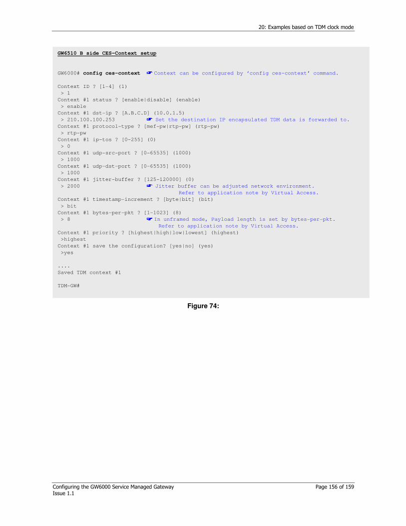
20: Examples based on TDM clock mode
Configuring the GW6000 Service Managed Gateway Page 156 of 159 Issue 1.1
Figure 74:
GW6510 B side CES-Context setup
GW6000# config ces-context Context can be configured by ‘config ces-context’ command.
Context ID ? [1-4] (1)
> 1
Context #1 status ? [enable|disable] (enable)
> enable
Context #1 dst-ip ? [A.B.C.D] (10.0.1.5)
> 210.100.100.253 Set the destination IP encapsulated TDM data is forwarded to.
Context #1 protocol-type ? [mef-pw|rtp-pw] (rtp-pw)
> rtp-pw
Context #1 ip-tos ? [0-255] (0)
> 0
Context #1 udp-src-port ? [0-65535] (1000)
> 1000
Context #1 udp-dst-port ? [0-65535] (1000)
> 1000
Context #1 jitter-buffer ? [125-120000] (0)
> 2000 Jitter buffer can be adjusted network environment.
Refer to application note by Virtual Access.
Context #1 timestamp-increment ? [byte|bit] (bit)
> bit
Context #1 bytes-per-pkt ? [1-1023] (8)
> 8 In unframed mode, Payload length is set by bytes-per-pkt. Refer to application note by Virtual Access.
Context #1 priority ? [highest|high|low|lowest] (highest)
>highest
Context #1 save the configuration? [yes|no] (yes)
>yes
....
Saved TDM context #1
TDM-GW#

21: Troubleshooting
Configuring the GW6000 Service Managed Gateway Page 157 of 159 Issue 1.1
21 Troubleshooting
21.1 Configuring system information warning and error messages
Error
message
Solution
%
Gateway
is
unreacha
ble
Check the gateway and IP address exist in the same subnetwork domain
Invalid IP
Address
Check the address is a valid range and value
Normally, network, broadcast, out of range addresses are an invalid value
Subnet mask Invalid address Valid address
IP bit
decimal Broadcast Network
Range
8 255.0.0.0 200.255.255.255
200.0.0.0
200.0.0.1~200.255.255.254
16
255.255.0.0 200.1.255.255
200.1.0.0
200.1.0.1~200.1.255.254
… … … … …
29
255.255.255.248
200.1.1.7 200.1.1.0
200.1.1.1~200.1.1.6
200.1.1.1
30
255.255.255.252
200.1.1.3 200.1.1.0
200.1.1.1, 200.1.1.2
httpd is
running!!,
do not
enable
%ssl
server
already
enabled
The command is rejected because SSL daemon status is already enabled.
% syslog
is already
enabled
The command is rejected because syslog agent daemon status is already enabled.
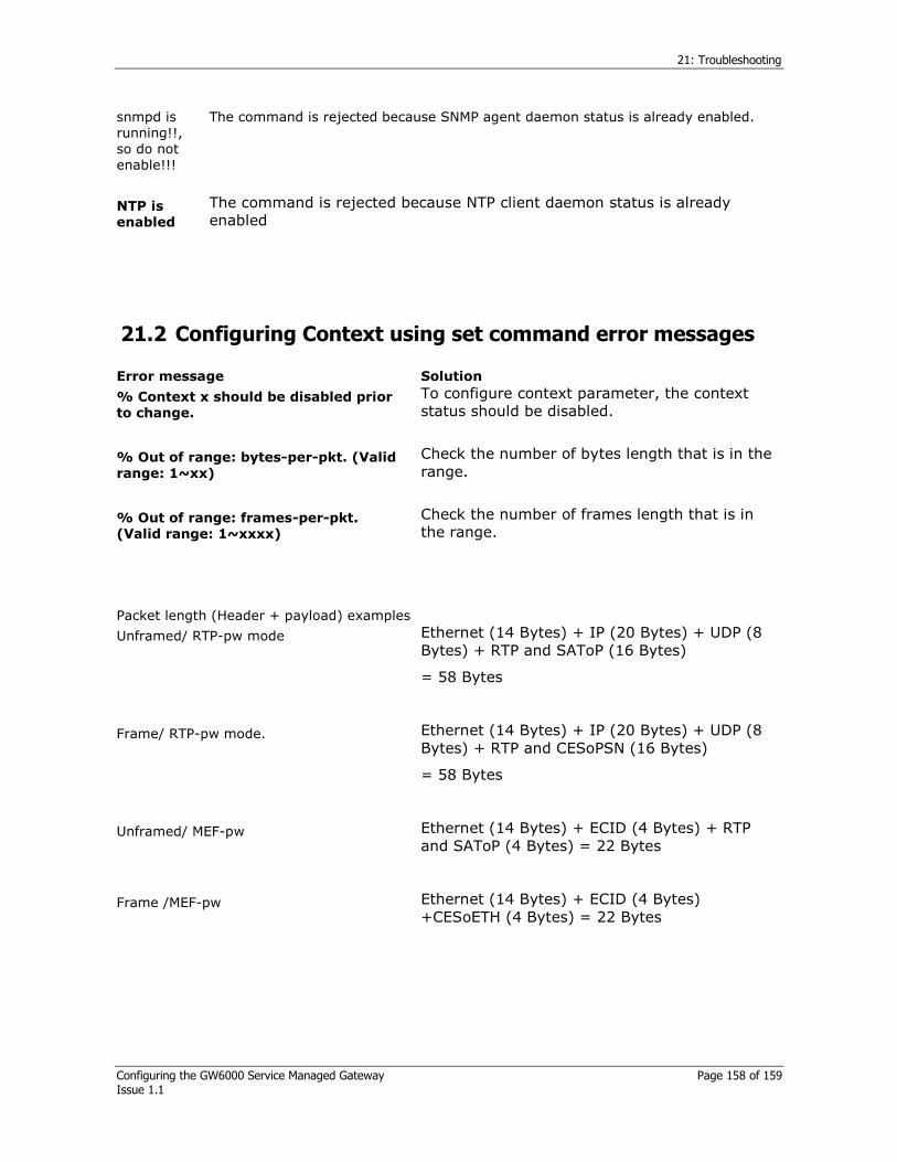
21: Troubleshooting
Configuring the GW6000 Service Managed Gateway Page 158 of 159 Issue 1.1
snmpd is running!!, so do not enable!!!
The command is rejected because SNMP agent daemon status is already enabled.
NTP is
enabled
The command is rejected because NTP client daemon status is already enabled
21.2 Configuring Context using set command error messages
Error message Solution
% Context x should be disabled prior
to change.
To configure context parameter, the context status should be disabled.
% Out of range: bytes-per-pkt. (Valid
range: 1~xx)
Check the number of bytes length that is in the range.
% Out of range: frames-per-pkt.
(Valid range: 1~xxxx)
Check the number of frames length that is in the range.
Packet length (Header + payload) examples
Unframed/ RTP-pw mode
Ethernet (14 Bytes) + IP (20 Bytes) + UDP (8 Bytes) + RTP and SAToP (16 Bytes)
= 58 Bytes
Frame/ RTP-pw mode.
Ethernet (14 Bytes) + IP (20 Bytes) + UDP (8 Bytes) + RTP and CESoPSN (16 Bytes)
= 58 Bytes
Unframed/ MEF-pw
Ethernet (14 Bytes) + ECID (4 Bytes) + RTP and SAToP (4 Bytes) = 22 Bytes
Frame /MEF-pw
Ethernet (14 Bytes) + ECID (4 Bytes) +CESoETH (4 Bytes) = 22 Bytes

21: Troubleshooting
Configuring the GW6000 Service Managed Gateway Page 159 of 159 Issue 1.1
21.3 SNMP Configuration warning and error messages
Error message Solution
% previously used community-name Check the community name is not duplicated.
snmpd is running!!, so do not enable SNMP agent daemon is already enabled.
21.4 NTP configuration warning and info messages
Error message Solution
NTP is enabled, disable first Disable NTP daemon to configure NTP parameters.
25 Apr 10:20:11 ntpdate[170]: no server suitable for synchronisation found
System date cannot be set up because there is no response from NTP server
Check the connection with NTP server and NTP server status.
25 Apr 10:18:14 ntpdate[144]: set time from server 10.20.252.7
NTP server synchronises system date and time.


