Embed Size (px)
Citation preview

Gulliver: Design and Implementation of aMiniature Vehicular SystemMaster of Science Thesis in the Programme CommunicationEngineering
BENJAMIN VEDDER
Chalmers University of Technology
University of GothenburgDepartment of Computer Science and EngineeringGoteborg, Sweden, November 2012

The Author grants to Chalmers University of Technology and University of Gothen-burg the non-exclusive right to publish the Work electronically and in a non-commercialpurpose make it accessible on the Internet. The Author warrants that he/she is theauthor to the Work, and warrants that the Work does not contain text, pictures or othermaterial that violates copyright law.
The Author shall, when transferring the rights of the Work to a third party (for examplea publisher or a company), acknowledge the third party about this agreement. If theAuthor has signed a copyright agreement with a third party regarding the Work, theAuthor warrants hereby that he/she has obtained any necessary permission from thisthird party to let Chalmers University of Technology and University of Gothenburg storethe Work electronically and make it accessible on the Internet.
Gulliver: Design and Implementation of a Miniature Vehicular System
Benjamin Vedder
c© Benjamin Vedder, November 2012
Examiner: Elad M. Schiller
Chalmers University of Technology University of Gothenburg Department of ComputerScience and Engineering SE-412 96 Goteborg Sweden Telephone + 46 (0)31-772 1000
Cover: Photo of the Gulliver 1:8 Car with the 9-degrees-of-freedom sensor removed.
Department of Computer Science and EngineeringGoteborg, Sweden, November 2012

Abstract
Traffic increases all over the world and problems such as toxic emissions and congestionare consequences of that. To encounter those problems and to optimize traffic throughputand safety, a miniature vehicular test platform that can be used together with simulationtools can be very useful.
This project deals with the construction, control, communication and navigation of theautonomous 1:8 scale miniature vehicles used in the Gulliver project. The goal is tomake the vehicles drive along a generated route, do lane changing between routes andto write software to interface with these vehicles.
Part of the work has been spent on a custom motor controller used to control brushlessDC motors, for which many safety mechanisms were implemented. Other areas cov-ered include the fusion of several sensors with Ranging and Communication Modulesto achieve indoor localization and algorithms to drive the vehicle autonomously alonga pre-defined route while accepting high-level commands such as stop, go and changelanes from external sources. Another part of the project was to evaluate the high-levelcommands using MICAz motes that run a virtual service agent to act as virtual trafficlights.
At the end all of the goals were achieved and the vehicles were able to drive along aroute and accept commands from the MICAz motes. This is very useful as many detailsthat not always are covered by pure simulations can be included while it is much easierand less costly than the same implementation with full-scale vehicles.


Acknowledgements
I would like to thank Elad Michael Schiller and Roger Johansson for their guidanceduring this project, it would not have been possible for me to achieve the same resultwithout their help. Further, I would like to thank Mohamed Mustafa and Mitra Pahlavanfor their help with the MICAz motes and their participation with the evaluation of thesystem. It is thanks to them that the entire system could be evaluated with a simplerealistic scenario at all.
There were also many bachelor students involved in this project, and I would like toexpress my gratitude to all of them:
Alexander AltbyTobias BostromErik DahlgrenJohan GrundenDaniel GunnarsonNadia HoltrydAnmar KhazalTimur SibgatullinKarl StjarneViktor Swantesson
Further, I would like to thank everyone at Chalmers Robotics Society (CRF) who par-ticipated in the construction of the Gulliver vehicles:
Peter KaldenErik SternaNigul IlvesMikael TulldahlMichael Nilsson
I would also like to thank Henk Wymeersch and Gabriel Garcia for their expertise regard-ing the localization of the vehicles. Further, I would like to thank Brandon Dewberryfrom TimeDomain for visiting us at Chalmers and for holding a seminar about the P400RCMs.
It was privileged and honoured for me to work with so many brilliant people during thisproject.
Benjamin Vedder - Wednesday 14th November, 2012


Glossary
ACK acknowledgement. 26
ADC Analog-to-Digital Converter. 13
BEMF Back Electro-Motive Force. 6, 13
BLDC Brushless Direct Current. 5, 6, 13, 14
Bluetooth is a wireless technology standard for exchanging data over short distances.24
commutation is the act of switching the polarity between different windings in anelectric motor to make the electromagnetic force contribute to the same angulardirection at all times. 5, 6, 9, 15
CRC Cyclic Redundancy Check. 16, 17, 25, 26
DC Direct Current. 5
dead reckoning is (in this project) the process of estimating a vehicles position byadvancing the previous position based on data from encoders in the wheels andthe steering angle. 6, 7, 10, 21
DOF Degrees of Freedom. 10, 21, 24
encoder is a device that converts mechanical movement into electrical pulses. i, 5, 9
GUI Graphical User Interface. ii, 5, 7, 8, 25, 26
IDE Integrated Development Environment. 8
i
Glossary
Linux (or GNU/Linux) is a Unix-like computer operating system that uses the Linuxkernel. 7
MAC Media Access Control. 3
MATLAB (matrix laboratory) is a numerical computing environment. 13, 15
MICAz is a 2.4 GHz Mote module, which is able to exchange data with other MICAzmotes. 4, 11, 24, 28, 31
mini-ITX is a 17x17 cm motherboard form factor. 9, 11, 24
MOSFET Metal–Oxide–Semiconductor Field-Effect Transistor. 5
PCB Printed Circuit Board. 13
PID Proportional–Integral–Derivative. 15
PWM Pulse Width Modulation. 13–15
Qt is a cross-platform application framework that is used for developing software witha Graphical User Interface (GUI). In addition to the GUI, Qt also provides func-tionality in many other areas, such as Transmission Control Protocol (TCP) con-nections (see http://qt.nokia.com/). 4, 7–9, 18, 23, 25, 26
RC Radio Controlled. 1, 5
RCM Ranging and Communications Module. 2, 3, 7, 11, 12, 16, 21, 24, 30
RF Radio Frequency. 24
route is in this document defined a set of points that define a path for vehicles to follow.2–4, 21–23
TCP Transmission Control Protocol. ii, 7, 11, 24–26
UART Universal Asynchronous Receiver/Transmitter. 10, 11, 13, 15–17, 24
USB Universal Serial Bus. 24, 25
UWB Ultra Wideband. 11
Wi-Fi is a technology that allows devices to exchange data wirelessly over a computernetwork. 25
ii

Contents
1 Introduction 11.1 Goal of this Work . . . . . . . . . . . . . . . . . . . . . . . . . . . . . . . . 11.2 Previous and Related Work . . . . . . . . . . . . . . . . . . . . . . . . . . 2
1.2.1 The Initial Construction of the Gulliver Vehicles . . . . . . . . . . 21.2.2 The Localization Project . . . . . . . . . . . . . . . . . . . . . . . 31.2.3 The Integration Project . . . . . . . . . . . . . . . . . . . . . . . . 4
1.3 Delimitations . . . . . . . . . . . . . . . . . . . . . . . . . . . . . . . . . . 4
2 Theory and Related Studies 52.1 The Gulliver Platform . . . . . . . . . . . . . . . . . . . . . . . . . . . . . 52.2 Basics of Brushless Direct Current Motors . . . . . . . . . . . . . . . . . . 6
2.2.1 Sensored Compared to Sensorless Commutation . . . . . . . . . . . 62.3 Localization and Navigation in Mobile Robot Platforms . . . . . . . . . . 7
2.3.1 Motion Planning . . . . . . . . . . . . . . . . . . . . . . . . . . . . 72.4 GUI and Network Programming . . . . . . . . . . . . . . . . . . . . . . . 8
2.4.1 The Functionality of the GTK+, Qt and WxWidgets Toolkits . . . 82.4.2 Ease of Use and Documentation for the GTK+, Qt and WxWid-
gets Toolkits . . . . . . . . . . . . . . . . . . . . . . . . . . . . . . 8
3 Brief System Overview 103.1 The Motor Controller . . . . . . . . . . . . . . . . . . . . . . . . . . . . . 103.2 The Main Controller . . . . . . . . . . . . . . . . . . . . . . . . . . . . . . 113.3 The Sensor Board and the 9-Degrees of Freedom Board . . . . . . . . . . 113.4 The Ranging and Communication Module . . . . . . . . . . . . . . . . . . 123.5 The MICAz Interface . . . . . . . . . . . . . . . . . . . . . . . . . . . . . . 123.6 The Sensors Board . . . . . . . . . . . . . . . . . . . . . . . . . . . . . . . 133.7 The External Interface Board . . . . . . . . . . . . . . . . . . . . . . . . . 133.8 The Mini-ITX Computer . . . . . . . . . . . . . . . . . . . . . . . . . . . 143.9 The Anchors . . . . . . . . . . . . . . . . . . . . . . . . . . . . . . . . . . 14
iii

CONTENTS
4 The Motor and its Controller 154.1 Sensorless Commutation . . . . . . . . . . . . . . . . . . . . . . . . . . . . 154.2 Speed Controller . . . . . . . . . . . . . . . . . . . . . . . . . . . . . . . . 174.3 Communications to the Main Controller . . . . . . . . . . . . . . . . . . . 184.4 Safety Considerations . . . . . . . . . . . . . . . . . . . . . . . . . . . . . 19
5 The Main Controller and Related Software 205.1 The Localization Algorithm . . . . . . . . . . . . . . . . . . . . . . . . . . 20
5.1.1 Position Updates Based on Tachometer and Steering Servo . . . . 225.1.2 Position Updates Based on the Ranging and Communications Mod-
ule . . . . . . . . . . . . . . . . . . . . . . . . . . . . . . . . . . . . 235.1.3 Position Updates Based on the 9-Degrees of Freedom Sensor . . . 23
5.2 How Navigation is achieved . . . . . . . . . . . . . . . . . . . . . . . . . . 235.2.1 The Lane Changing Algorithm . . . . . . . . . . . . . . . . . . . . 255.2.2 Adaptive Cruise Control . . . . . . . . . . . . . . . . . . . . . . . . 25
5.3 Local and External Communications . . . . . . . . . . . . . . . . . . . . . 255.3.1 Local Communications . . . . . . . . . . . . . . . . . . . . . . . . . 255.3.2 External Communications . . . . . . . . . . . . . . . . . . . . . . . 27
5.4 The Gulliver Client Program . . . . . . . . . . . . . . . . . . . . . . . . . 28
6 A simple Traffic Scenario Application 306.1 Suggested Improvements . . . . . . . . . . . . . . . . . . . . . . . . . . . . 30
7 Conclusions 327.1 Suggested Future Work . . . . . . . . . . . . . . . . . . . . . . . . . . . . 32
Bibliography 36
Appendix A 40
iv
1
Introduction
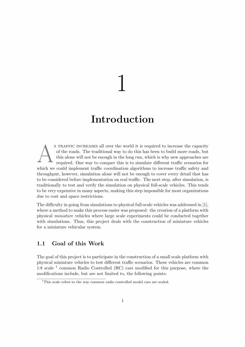
As traffic increases all over the world it is required to increase the capacityof the roads. The traditional way to do this has been to build more roads, butthis alone will not be enough in the long run, which is why new approaches arerequired. One way to conquer this is to simulate different traffic scenarios for
which we could implement traffic coordination algorithms to increase traffic safety andthroughput, however, simulation alone will not be enough to cover every detail that hasto be considered before implementation on real traffic. The next step, after simulation, istraditionally to test and verify the simulation on physical full-scale vehicles. This tendsto be very expensive in many aspects, making this step impossible for most organizationsdue to cost and space restrictions.
The difficulty in going from simulations to physical full-scale vehicles was addressed in [1],where a method to make this process easier was proposed: the creation of a platform withphysical miniature vehicles where large scale experiments could be conducted togetherwith simulations. Thus, this project deals with the construction of miniature vehiclesfor a miniature vehicular system.
1.1 Goal of this Work
The goal of this project is to participate in the construction of a small scale platform withphysical miniature vehicles to test different traffic scenarios. These vehicles are common1:8 scale 1 common Radio Controlled (RC) cars modified for this purpose, where themodifications include, but are not limited to, the following points:
1This scale refers to the way common radio controlled model cars are scaled.
1

1.2. PREVIOUS AND RELATED WORK CHAPTER 1. INTRODUCTION
• Localization for all the vehicles that is accurate and fast enough to make it possibleto drive the vehicles autonomously.
• The vehicles should be able to accept high level commands such as stop, go andchange lane. Moreover, remote programming of main functionality should be al-lowed.
• Possibility to remote control the vehicles and to record routes should be present.This means that one should be able to drive one vehicle and record the drivenpath, and store it as a route.
• It should be possible to upload the routes to a computer, change and downloadthem to the vehicle again. It should also be possible to download routes to thevehicle that are completely generated by software on a computer.
• On-board sensors on the vehicle should avoid driving into obstacles even if thenavigation and control software claim that there is nothing in the way. This reducesthe necessity to externally monitor the area where the vehicles drive to avoidunexpected objects.
1.2 Previous and Related Work
Two vehicles were constructed, assembled and partly tested in another project [2, seeAppendix A] in collaboration with the work of this project. Parallel to this project, otherprojects on different aspects of these vehicles and their integration into other systemswere also carried out, where one project focused on improving the localization of thevehicles [3] and the other one focused on integrating the Gulliver vehicles into othersystems [4].
1.2.1 The Initial Construction of the Gulliver Vehicles
Part of this project was to participate in a project where the initial construction of theGulliver vehicles was conducted [2, see Appendix A]. In this project, two vehicles wereconstructed and very basic software was written to test the functions of the differentsystems on the vehicles. At the end of this project, one vehicle was able to follow ahard-coded route to some extent.
While this was a great step in the progress of constructing vehicles as proposed in [1],there were many things left to be done in order to reach the goal. The following listpoints out a number of those issues, which this project report will focus on:
• When two vehicles were driving at the same time they interfered with each otherand the accuracy for the position decreased. When switching on another one ofthe Ranging and Communications Modules (RCMs), effectively adding another
2

1.2. PREVIOUS AND RELATED WORK CHAPTER 1. INTRODUCTION
vehicle to the ranging network, the localization got too much interference due tocollisions that navigation became impossible. This issue will mainly be addressedin [3], however, there was much collaboration between this project and their work.
• The localization had a very simple algorithm that did not consider the quality ofthe measurements from the different sources even if the information was there.For instance, the RCMs provide an indication about the quality of each rangemeasurement [5] that was not taken into account. Like the previous issue, this willbe addressed in [3] with collaboration from this project.
• There was no way to upload new routes to the vehicles while they were driving,so in order to change the route the firmware had to be changed by connectinga programming cable and uploading it. As the routes (and the firmware) werechanged often during the experiments much time was used for picking up thevehicles, reprogramming them, and putting them back on the floor. This is one ofthe areas that was focused on during this project by implementing the necessarycommunication links and computer programs to remotely reconfigure the vehicles.
• An RF-transceiver was used to communicate with one vehicle at a time. There wasno way to receive data from more than one vehicle at a time and the transmissionpower was low enough to cause lost packets frequently. Like the previous point,this was addressed during this project.
• The motor controller didn’t have enough ”sanity checks”for the received commands,which caused defective electronic components when certain errors were present inthe program of the main controller on the vehicle. One of the main tasks of thisthesis was to improve the motor controller and fix these issues.
1.2.2 The Localization Project
The localization project [3] was carried out in parallel to this project. This project’spurpose was to improve the localization on the vehicles in two different areas: improvingthe algorithm for the position estimation and making the localization work with manyvehicles at the same time.
In order to make the position estimation more accurate a Kalman filter [6] was used. Thisfilter merged data from the RCMs and the on-board sensors of the vehicle to estimatethe vehicle current position and a confidence interval around that position.
To coordinate the ranging of the vehicles in a way that avoids collisions was the othermajor part of this project. For this purpose a custom Media Access Control (MAC)layer was created that uses one or multiple communication units on the vehicle to keepa global clock and coordinate the ranging operations. The so-called timeslot manageradapted the timing scheme for the ranging dynamically when new vehicles entered orleft the area.
3

1.3. DELIMITATIONS CHAPTER 1. INTRODUCTION
1.2.3 The Integration Project
In the integration project [4], the Gulliver vehicles were connected to MICAz motes usedto interact with the SUMO simulator [7]. This was carried out in parallel to this projectand the external interface to the vehicles was tested together with this project. One partof this project was to drive simulated vehicles together with the physical vehicles on thesame virtual map and make the simulated and physical vehicles aware of each other. Atthe end this worked quite well and a demonstration of this was made [4].
Another part of this project was to work on a map editor to create routes for the vehicles.This was done in close collaboration with the work on the external interface written inQt during this project.
1.3 Delimitations
The miniature vehicle proposed in [1] leave room for a large number of possibilities, andobviously not all of them can be implemented in full detail the scope of this mastersthesis. Therefore, it is important to make it clear that only the most important featuresnecessary to show the basic concept of the vehicles were implemented. Also, the featuresthat were implemented, such as the localization and navigation algorithms, leave roomfor further development. Further, the system will not be tested with a large number ofphysical vehicles due to resource and time limitations.
Another thing to point out is that this paper does not cover all the details of the im-plementations made, but only the concepts and the most important details. There areapproximately 25000 lines of C/C++ code written for the microcontrollers and the desk-top computer programs. The entire design of the printed circuit boards, source code anda construction tutorial can be retrieved via the Gulliver website 1.
1www.gulliver-testbed.net.
4

2
Theory and Related Studies
This chapter covers fields and studies related to this project. Many decisionsregarding the design and implementation of different systems on the vehicleswere made based on the material that is reviewed and compared here. Moreprecisely, this chapter covers: background about the Gulliver platform, Brush-
less Direct Current (BLDC) motors, localization and Graphical User Interface (GUI)programming.
2.1 The Gulliver Platform
In order to determine what is required by the Gulliver vehicles, it is important to studythe environment in which they are going to operate. As is described in [1], the vehiclesare going to work together with a motion manager (the MICAz mote, see Chapter 6 forfurther details) which will provide high-level commands to perform different maneuvers.Therefore, it is important that the vehicles are aware of their own location and havealgorithms to perform motion planning. To make it convenient to work with the simula-tor mentioned in [1] and to debug the vehicles, it is also important to have an interfacewhere maps and routes can be edited and visualized. It is also important to plot thevehicles on these maps in real-time to see how they perform and what is observed fromtheir perspective. The GUI that is developed in this project to control the vehicles canbe compared to the base station described in [1].
With this considered, the additions required for a common RC car to suite the Gulliverplatform are:
• A good motor controller to give precise control of the maneuvers of the vehicles.
5

2.2. BLDC MOTOR BASICS CHAPTER 2. THEORY
• Hardware and software able to carry localization and navigation in real-time.
• The necessary interface software to control and debug the experiments made withthis platform.
How all of this fits together will be presented in this project report.
2.2 Basics of Brushless Direct Current Motors
For model RC cars and other smaller motor-driven applications it is common to usebrushed Direct Current (DC) motors because they are easy to control, however, theyhave a few drawbacks compared to BLDC motors:
• They require more maintenance because the brushes wear out.
• Their power density and efficiency is lower.
• Since the commutation is done mechanically, brushed DC motors cannot be usedas pulse encoders. The angular speed of the motor can only be estimated bymeasuring the current and voltage, unless an external encoder is used.
In comparison, the BLDC motor does not suffer from those issues. With a custom motorcontroller one has good knowledge about the angular position of the rotor and the motorrequires very little maintenance since there are essentially no parts that wear out. Thedrawback is that those motors are more difficult to control. The reason for that is thatinstead of mechanically switching between the different windings for the commutation,as is the case with the brushed motor, the windings of the motor are stationary andthe commutation is done electronically with Metal–Oxide–Semiconductor Field-EffectTransistors (MOSFETs). In order for this to work the position of the motor has to beknown at all times, which is a problem that has two possible solutions:
1. Sensored commutation: sensors mounted in the motor are used to detect itsposition.
2. Sensorless commutation: as one of the connections of the motor is alwaysfloating, i.e., is not connected to any of the power rails, it can be used to detectthe position of the motor by measuring the Back Electro-Motive Force (BEMF) ofthe motor.
2.2.1 Sensored Compared to Sensorless Commutation
Sensored commutation works very well from startup of the motor until high speedswithout glitches and is relatively easy to implement on the motor controller; which isbecause the sensors directly provide the position of the rotor and it is easy to readthem. The problem is that it only works for BLDC motors with sensors, which are
6

2.3. LOCALIZATION AND NAVIGATION CHAPTER 2. THEORY
a bit more difficult to find and more expensive. On the contrary, a motor controllerdesigned for sensorless BLDC motors works with any motor and requires less wires andless components. The drawback is that it is harder to implement the motor controllerand most methods used to control the motors have limitations during startup and lowspeeds [8, 9]. This is because the BEMF created by the motor, used to detect its position,is proportional to the rotational speed of the motor and hence non-existent when themotor is not moving.
The most common way to start sensorless BLDC motors, as proposed in [8, 9], is touse a known sequence of commutations based on knowledge about the motor and itsload, and then switch to closed loop control when the motor speeds up. There are alsomore advanced ways to start BLDC motors that rely on heavier calculations and moreaccurate measurement of the BEMF [10] where the start is smoother.
2.3 Localization and Navigation in other Mobile RobotPlatforms
Indoor localization and motion planning are common issues when dealing with mobilerobot platforms. One platform where these issues were encountered by the developersis the autonomous robot Blanche [11]. Blanche is a three-wheeled cart designed tonavigate autonomously in structured office environments. Blanche navigates based ondead reckoning and on-board sensors which are combined to estimate its current position.It is assumed that a path, consisting of straight lines and circle segments, is provided inadvance for the cart to follow. The cart controller will continuously update the motoroutput power and steering angle based on the reference position and feedback from themotor odometry and a model for the movement of the cart.
The concept of combining different sensors to estimate the current position will be imple-mented for the Gulliver vehicles as well. The dead reckoning will be attempted almostidentical to the way it is done on Blanche, however, the RCMs will provide a moreaccurate position than the other sensors on Blanche.
2.3.1 Motion Planning
The path for the Gulliver Vehicles consists of a set of points and the vehicles themselvesmake decisions on how to drive to the next point based on the current position, perform-ing simple motion planning. One way to do motion planning, as suggested by [12], is tocalculate a number of paths to reach the goal and pick the best one based on minimizingthe cost to of the selected path. This optimization takes the distance, speed and energyconsumption into account and many details on how to do this are provided. Even thoughthe areas covered in this paper are relevant for the Gulliver project, most of them arenot implemented during the work in this project as it would require considerably more
7

2.4. GUI AND NETWORK CHAPTER 2. THEORY
time than there is available. It should however be noted that more advanced motionplanning, as suggested in this paper [12], would be very useful for work on the Gullivervehicles in the future.
2.4 GUI and Network Programming
As a major part of this project involves writing a GUI to control the vehicles andcommunicating over a Transmission Control Protocol (TCP) network, it is importantto choose a toolkit that can handle those tasks. The work will be performed using theLinux operating system, so it is important that the chosen toolkit will run on Linux.Three modern and common such toolkits are GTK+ [13], Qt [14] and WxWidgets [15].These toolkits will be compared in the areas of functionality and how easy they are touse.
2.4.1 The Functionality of the GTK+, Qt and WxWidgets Toolkits
Regarding the ability to draw GUI components (or widgets), all toolkits are able to dothe job. Qt and GTK will draw widgets by themselves trying to emulate the behaviourof the operating system, while WxWidgets will use the native widgets provided by theoperating system. For comparison, a few aspects of the languages will be considered:
Multi-threading, which is important because network communications often take rel-atively long time, is supported on GTK+ and WxWidgets to some extent; however ithas to be handled carefully and can cause many problems [13, 15]. On the contrary, Qthas been designed with multi-threading in mind and threads can easily be synchronizedwith not only mutexes, but also with signals and slots [14]. This gives Qt an advantageregarding multi-threading.
Network Support, which is built into WxWidgets and Qt. GTK+ lacks built-inlibraries with network support. However, external libraries could be used to providethis functionality 1. When comparing the network support in Qt with WxWidgets, Qt’snetwork classes are more feature rich and provide better multi-threading support [14, 15].This, again, gives Qt an advantage.
2.4.2 Ease of Use and Documentation for the GTK+, Qt and WxWid-gets Toolkits
Both GTK+ and Qt have excellent and updated documentation available online whichmakes it obvious where to get started 2. Qt also has an Integrated Development Environ-
1see http://developer.gnome.org/gnet/.2see http://doc.qt.nokia.com/ and http://www.gtk.org/documentation.php.
8

2.4. GUI AND NETWORK CHAPTER 2. THEORY
ment (IDE) with built-in documentation and examples, called QtCreator 3, which makesit very easy to find documentation during the development process. On the contrary,WxWidgets lacks in some areas of the documentation and often refers to a book that isseven years old at the time of this writing [15]; it is not obvious how to get started whenusing WxWidgets. Thereby, GTK+ and Qt have an advantage over WxWidgets in thearea of documentation.
It should also be noted that both GTK+ and Qt provide a graphical GUI designer wherecomponents easily can be dragged and dropped [13, 14] to create the GUI, whereasWxWidgets doesn’t provide any open-source GUI designer.
At the end, it was decided to use the Qt toolkit to write the GUI and the networkinterface as it seems to have the most advantages for this task.
3see http://qt.nokia.com/products/developer-tools.
9

3
Brief System Overview
In this chapter a brief description will be given about each one of the subsystems onthe Gulliver vehicles in order to provide a picture about the whole system, to makeit easier to follow later when the subsystems are described in detail. An overviewof the system on the vehicles can be seen in the block diagram in Figure 3.2.
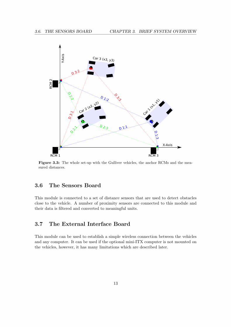
Each vehicle consists of a network of nodes connected over the same, or independent,communication buses. Some of the nodes are connected to actuators and others areconnected to sensors. Where everything is located on the physical vehicles can be seenin Figure 3.1. The system of several vehicles and anchors along with the distancesmeasured by ranging can be seen in Figure 3.3.
The work in this project involves every system described in this section to some extent;in particular the main controller, the motor controller and the mini-ITX computer. A lotof effort was also spent into writing a program using the Qt framework to communicatewith and control the Gulliver vehicles.
3.1 The Motor Controller
This node is responsible for controlling the main motor and the steering servo. The mainmotor has built-in sensors used to detect the position of the motor for commutation,which additionally are used as encoders for sensing the travelled distance. The steeringservo has an internal control system for the positioning of the front wheels. The motorcontroller only communicates with the servo in one direction when setting the desiredsteering angle and the rest of the system on the vehicle will assume that the servo is atthe requested position at all times. Because of the importance of the motor controller ithas it’s own communication bus.
10

3.2. THE MAIN CONTROLLER CHAPTER 3. BRIEF SYSTEM OVERVIEW
Figure 3.1: Location of the different components on the Gulliver vehicle. The 9-Degreesof Freedom sensor is not attached in this picture. It is located on a stick attached to thevehicle, so it can easily be seen on the real vehicle.
3.2 The Main Controller
The main controller communicates with the other nodes on the vehicle and runs the al-gorithms for localization, dead reckoning and sensor data fusion. Further, the algorithmsfor autonomous driving (or navigation) of the vehicle also run on this one.
3.3 The Sensor Board and the 9-Degrees of Freedom Board
The sensor board and the 9-Degrees of Freedom (DOF) board are responsible for col-lecting data from external sensors on the vehicle and applying some rough scaling andfiltering to it. These boards are connected to the same multi-Universal AsynchronousReceiver/Transmitter (UART) bus.
11

3.4. THE RCM CHAPTER 3. BRIEF SYSTEM OVERVIEW
9 DOF SensorDOF = Degrees of Freedom
AdapterMultiUART
MultiUART
Sensor Board
MultiUART
MultiUART
MultiUART
Main Controller
RF USB(USB-to-UART)
UART(for MC)
Motor Controller
UART
Sensors
Mini-ITX Computer(optional)
USB Port1 2
3 4
5 6
Multi-UARTContact
1.
2.
3.
4.
6.
5.
Vdd
GND
Rx
Tx
GND
Battery
Fail-safe connectionputting the contact in the socket
incorrect will NOT damage the circuits RF USB(USB-to-UART)
Bluetooth
Interface BoardAn USB-to-RF adapter
Servo(for steering)
UA
RT
(for
RC
M)
P400 RCM(Localization Board)
UART
P400 RCMAnchor
Motor
MultiUART
MultiUART
MICAz Interface Board
Wi-Fi Ethernet
GulliverVehicle
UART
UART
MICAz Mote
Figure 3.2: Overview of the control system on the vehicles
3.4 The Ranging and Communication Module
The RCM [16] is connected directly to the main controller via UART and is used tomeasure the distance to fixed anchors on the area where the vehicle navigates, therebyproviding an absolute position reference. The RCMs use Ultra Wideband (UWB) radiosto measure the time-of-flight of the signal to calculate the distance between them.
3.5 The MICAz Interface
This is an interface board used for communicating between the Gulliver Vehicle andMICAz motes. Many of the people who are involved with this project are familiar withthe MICAz motes, so therefore it is important that they can be used with the Gullivervehicles.
12
3.6. THE SENSORS BOARD CHAPTER 3. BRIEF SYSTEM OVERVIEW
X-Axis
Y-A
xis
Car 1
(x1,
y1)
Car 2 (x
2, y2)
Car 3 (x3, y3)
RCM 1
RC
M 2
RCM 3
D 3:2D
3:1
D3:3D 1:2
D 1:1
D1:3
D2:
1 D 2:3
D2:2
Figure 3.3: The whole set-up with the Gulliver vehicles, the anchor RCMs and the mea-sured distances.
3.6 The Sensors Board
This module is connected to a set of distance sensors that are used to detect obstaclesclose to the vehicle. A number of proximity sensors are connected to this module andtheir data is filtered and converted to meaningful units.
3.7 The External Interface Board
This module can be used to establish a simple wireless connection between the vehiclesand any computer. It can be used if the optional mini-ITX computer is not mounted onthe vehicles, however, it has many limitations which are described later.
13
3.8. THE MINI-ITX COMPUTER CHAPTER 3. BRIEF SYSTEM OVERVIEW
3.8 The Mini-ITX Computer
The mini-ITX computer is optional and can be mounted in order to provide a convenientinterface to monitor, control and re-configure the vehicles wirelessly. This computer isconnected to a wireless network and to the main controller of the vehicle, running aTCP-server for remote access. This computer was not mounted previously [2] and thesoftware to communicate with it’s TCP-server was a major part of this project.
3.9 The Anchors
The anchors are RCMs that passively respond to ranging requests from the vehicles.The Gulliver vehicles know where the anchors are located and at least three anchors arerequired to determine the position of the vehicles. An illustration of this can be seen inFigure 3.3.
14

4
The Motor and its Controller
The motor controller is one of the central parts of the Gulliver vehicles andwill be addressed in this chapter. The motor of the vehicle is a permanentmagnet Brushless Direct Current (BLDC) motor with sensors to detect itsrotor position.
4.1 Experiments with Sensorless Commutation
The first two vehicles from the previous project [2] were equipped with sensored BLDCmotors, however, the construction of more vehicles was planned. Therefore it would bebeneficial to make the motor controller work with sensorless motors (see section 2.2.1).
Another revision of the motor controller Printed Circuit Board (PCB) was made with theaddition of Back Electro-Motive Force (BEMF) measurement with a resistor-capacitorvoltage divider, shown in figure 4.1, as proposed by an application note from Atmel[17]. The outputs from those three combined voltage dividers/filters were connected toAnalog-to-Digital Converter (ADC) inputs of the microcontroller on the motor controllerPCB.
With the BEMF measurement in place, the Universal Asynchronous Receiver/Transmit-ter (UART) link was connected to MATLAB and the measured back-emf was plottedwith a 3-sample mean value (figure 4.2) and a 3-sample median value (figure 4.3) filter.
The reason that the median filter performs much better is that, according to measure-ments with an oscilloscope, the noise is caused by the Pulse Width Modulation (PWM)switching noise. To avoid the switching noise and thus get a higher sampling rate withless computational power wasted on filtering, the ADC sampling could be synchronized
15

4.1. SENSORLESS COMMUTATION CHAPTER 4. MOTOR CONTROLLER
Figure 4.1: Resistor-Capacitor voltage divider/filter
Figure 4.2: The BEMF filtered with a 3-sample mean value filter
to the timer responsible for generating the motor control PWM [18]. However, the im-portant aspect of this experiment was to test the performance of the startup of themotor, so this was left for implementation in case it turns out that the startup workswell.
The startup was implemented in the most common way, as proposed by others [8, 9],and did the job to start the motor. However, the start was not very smooth and themotor was not able to handle sufficient loads when running slowly, so the decision afterthis experiment was to continue with the use of sensored BLDC motors.
16

4.2. SPEED CONTROLLER CHAPTER 4. MOTOR CONTROLLER
Figure 4.3: The BEMF filtered with a 3-sample median value filter. It can clearly be seenthat there is less noise compared to the mean-value filter.
4.2 Speed Controller
The motor controller is not only responsible for the commutation of the motor, but alsofor controlling its speed. The main controller of the vehicle will tell the motor controllerto run the motor at a certain speed and it is the task of the motor controller to adjustthe PWM in such a way that the requested speed is maintained as good as possible,regardless of the load on the motor. For this purpose a Proportional–Integral–Derivative(PID) controller is used. The current speed of the motor is determined by measuringand filtering the time between commutations, after which it is fed to the PID controller,where the PWM duty cycle is adjusted.
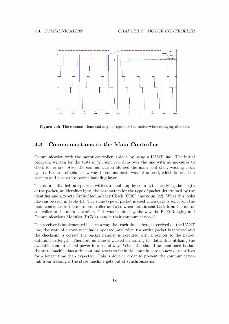
There are many ways to implement PID controllers [19, 20], and which method to choosedepends on the system to be controlled and the requirements of the implementation.In order to determine how difficult it is to control the motor, the step response wasmeasured using the UART connection and plotted using MATLAB (see figure 4.4). Asit turns out, the motor responds almost immediately and changes direction in less than10 milliseconds. It was also noted that the load the vehicle causes has no major influenceon the angular speed of the motor. Given this information, a very simple approach todesign the PID controller, as described by [21], was used. The resulting speed controlworked really well and was used for the motor controller.
17
4.3. COMMUNICATION CHAPTER 4. MOTOR CONTROLLER
Figure 4.4: The commutations and angular speed of the motor when changing direction
4.3 Communications to the Main Controller
Communication with the motor controller is done by using a UART line. The initialprogram, written for the tests in [2], sent raw data over the line with no measures tocheck for errors. Also, the communication blocked the main controller, wasting clockcycles. Because of this a new way to communicate was introduced, which is based onpackets and a separate packet handling layer.
The data is divided into packets with start and stop bytes, a byte specifying the lengthof the packet, an identifier byte, the parameters for the type of packet determined by theidentifier and a 2-byte Cyclic Redundancy Check (CRC) checksum [22]. What this lookslike can be seen in table 4.1. The same type of packet is used when data is sent from themain controller to the motor controller and also when data is sent back from the motorcontroller to the main controller. This was inspired by the way the P400 Ranging andCommunications Modules (RCMs) handle their communication [5].
The receiver is implemented in such a way that each time a byte is received on the UARTline, the state of a state machine is updated, and when the entire packet is received andthe checksum is correct the packet handler is executed with a pointer to the packetdata and its length. Therefore no time is wasted on waiting for data, thus utilizing theavailable computational power in a useful way. What also should be mentioned is thatthe state machine has a timeout and resets to its initial state in case no new data arrivesfor a longer time than expected. This is done in order to prevent the communicationlink from freezing if the state machine gets out of synchronization.
18

4.4. SAFETY CONSIDERATIONS CHAPTER 4. MOTOR CONTROLLER
Bytes Value Description
1 0x02 Start byte
1 N The length of the packet
1 X The identifier. Used to determine how to inter-pret the payload.
N - 1 X The payload of the packet
2 X A CRC checksum.
1 0x03 Stop byte
Table 4.1: Packet format for motor controller
4.4 Safety Considerations
A lot of power can be delivered by the motor (about 1.6 kW) and it is therefore importantthat nothing goes wrong easily. The following list names a number of methods that havebeen implemented in order to minimize the probability for accidents:
• Each packet sent over the UART communication link has a CRC checksum andwill only be used if the checksum corresponds to the payload. If data is altereddue to noise, the probability that the checksum passes is very low.
• If no new commands that specify how fast to drive the motor have been receivedfor more than 0.5 seconds, the motor will stop. So, if the vehicle is driving andsomeone disconnects the UART cable to the motor controller, the motor will stopafter 0.5 seconds.
• The power output to the motor cannot be changed too rapidly. For instance, ifthe motor is running at full speed in one direction and the direction is changed tofull speed in the reverse direction, the power will not be changed in one step; itwill be ramped down to zero and then ramped to the desired power in the otherdirection. This is to avoid braking mechanical and electronic parts.
• There is a programmable limit to the maximum speed of the motor; if a higherspeed is requested, it will be truncated to the highest allowed speed.
Based on experiments with the vehicles, this covers all trivial error sources encountered.There are still other things that can go wrong, such as requesting that the vehicledrives into a wall, but they cannot easily be avoided from the perspective of the motorcontroller. How other things than can go wrong are handled on the Gulliver vehicles canbe seen in chapter 5, section 5.2.2.
19

5
The Main Controller and RelatedSoftware
The main controller is where the algorithms for localization and navigationare carried out. Further, the communication between all modules is initiatedfrom here. This chapter will describe how the localization works, how al-gorithms for driving the vehicle are carried out and how the communication
between the vehicle and the Qt program to control the vehicle works. An overview aboutthe connection between the different pieces of software can be seen in figure 5.1.
5.1 The Localization Algorithm
The localization is achieved by combining different sources of information to make anestimate of the current position of the vehicle. This is a form of sensor fusion, whichis a common practice when dealing with mobile robots [23, 24]. The algorithm doesnot require all sensors to be connected at the same time and will handle removal andaddition of sensors dynamically with the current design.
The position of the vehicle is defined as its x- and y-position and angle θ on a two-dimensional coordinate system. The center of the vehicle is defined as the point betweenthe rear wheels. An illustration of this is shown in figure 5.2.
Part of the program running on the main controller is responsible for estimating thecurrent position of the vehicle, and has a set of methods to update the current positionbased on measurements from different sensors. These methods can be called in any orderand not all of them have to be used, which is why the program can handle different
20

5.1. LOCALIZATION CHAPTER 5. MAIN CONTROLLER
Main Controller
USB(USB-to-UART)
Min
i-IT
X C
om
pute
r USB Port
Com
munic
ati
on
to o
ther
contr
olle
rsW
i-Fi
/Eth
ern
et
TCP-to-UARTBridge
Program (Qt)
Lin
ux C
om
pute
r
Gulliver Vehicle
Gulliver InterfaceProgram (Qt)
External Client
USB Port
OptionalJoystick/Controller
USB
Wi-
Fi/E
thern
et
Figure 5.1: Overview of the external interface to the Gulliver vehicles
XY
θ
X-Axis
Y-Axis
Figure 5.2: Definition of the position for the Gulliver vehicles
amounts of sensors dynamically. It is possible to extend this with more sensors if a moreaccurate position estimate is required. The following parts will describe how some of the
21

5.1. LOCALIZATION CHAPTER 5. MAIN CONTROLLER
position update methods are implemented.
5.1.1 Position Updates Based on Tachometer and Steering Servo
The motor controller will continuously count the pulses the motor generates while movingand this value is read and reset from the main controller. This value is sent to thelocalization part of the program together with the last angle for the steering servo toupdate the position and angle of the vehicle. This assumes that the steering servo hasbeen in a constant position during that movement and that the tires do not slip too much.This method to update the position has very fast update rate and low noise, however,the estimation of the position will drift over time. In the C programming language, thisupdate looks like the following:
1 void dr update position angle(double ∗pos x, double ∗pos y, double ∗angle) {2 // Read the current steering angle3 const double steering angle = dr get steering angle();4 // Read the travelled distance from motor controller since last update5 const double travel distance = dr get travel distance();67 if (travel distance == 0) {8 // No movement since last update... abort9 return;
10 }1112 if (fabs(steering angle) < 0.001) {13 // Avoid division by zero.. approximate small angles as going straight14 ∗pos x += cos(∗angle) ∗ travel distance;15 ∗pos y += sin(∗angle) ∗ travel distance;16 } else {17 const double turn rad rear = DR AXIS DISTANCE / tan(steering angle);18 double turn rad front = sqrt(19 DR AXIS DISTANCE ∗ DR AXIS DISTANCE20 + turn rad rear ∗ turn rad rear);2122 if (turn rad rear < 0) {23 turn rad front = −turn rad front;24 }25 const double angle diff = (travel distance ∗ 2.0) / (turn rad rear + turn rad front);2627 ∗pos x += turn rad rear ∗ (sin(∗angle + angle diff) − sin(∗angle));28 ∗pos y += turn rad rear ∗ (cos(∗angle − angle diff) − cos(∗angle));29 ∗angle += angle diff;3031 // Make sure that the angle is within range (0 − 2PI)32 while (∗angle > 2.0 ∗ M PI) {33 ∗angle −= 2.0 ∗ M PI;34 }35 while (∗angle < 0) {36 ∗angle += 2.0 ∗ M PI;37 }38 }39 }
While this concept was developed and tested during the work of this project, the Local-ization Project [3] improved this function to also estimate a confidence interval for the
22

5.2. NAVIGATION CHAPTER 5. MAIN CONTROLLER
current position based on measurements made with the vehicle [3]. This was done bydriving the vehicle on the floor and measuring how much this position estimate deviatesfrom the actual position over distance.
Finally, it should be noted that this method to update the position of the vehicle willnot work alone for a long time as there is no absolute reference, thus the deviation willjust grow over time and has no upper bound.
5.1.2 Position Updates Based on the Ranging and CommunicationsModule
Every time the Ranging and Communications Module (RCM) ranges with one of theanchors the measured distance, the location of that anchor and the measured standarddeviation is sent to one specific position update method. This information is used tocorrect the x- and y-position of the vehicle. A Kalman-filter [6] is then used to updatethe estimated position of the vehicle and the current standard deviation. The algorithmfor this was part of the localization project [3], so the details will not be covered here. Itshould be noted that the angle of the vehicle (see angle θ in figure 5.2) is not correctedfrom the RCMs at the time of this writing, so additional means are required to correctthe angle of the vehicle.
5.1.3 Position Updates Based on the 9-Degrees of Freedom Sensor
The 9-Degrees of Freedom (DOF) sensor contains one three-axis accelerometer, onethree-axis gyroscope and one three-axis magnetometer; which are the 9-DOF. In thisapplication, only two out of three axes of the magnetometer are used to detect themagnetic field of the earth, effectively acting as a compass. This information is used tocorrect the angle of the Gulliver vehicles and is really important as the dead reckoning(see Glossary) depends on a correct angle to work properly.
5.2 How Navigation is achieved
The navigation, or the “driving algorithm”, assumes that the current position of thevehicle is always known and uses a map, defined as a set of routes (see figure 5.3), todrive the vehicle along one of the routes. The algorithm is called approximately 100times per second and in each iteration the motor controller is updated with a new speedand steering setpoint. The speed is calculated by weighting the desired speed of theprevious and next point on the current route with the relative distance to the points.The calculation looks as the following:
23

5.2. NAVIGATION CHAPTER 5. MAIN CONTROLLER
kprev =dnext
dprev + dnext(5.1)
v = vprev ∗ kprev + vnext ∗ (1 − kprev) (5.2)
where dnext is the distance to the next point on the route, dprev is the distance to theprevious point and v is the speed sent to the motor controller based on the set speed forthe previous and next point (vprev and vnext).
Figure 5.3: Map example in map editor with two routes (or lanes)
The steering angle is calculated such that the vehicle will follow an arc that goes throughthe next point on the current route. The steering angle also has a certain gain based onthe distance to the next point to avoid driving a long detour when the next point is faraway.
It should be noted that this navigation algorithm is very simple and that there are manyconsiderably more advanced path planning algorithms [12, 25], but it works well for thiscase as the map is relatively well defined.
24
5.3. COMMUNICATIONS CHAPTER 5. MAIN CONTROLLER
5.2.1 The Lane Changing Algorithm
Lane changing is the act of starting to follow another route from some point on thecurrent route. Lane changing can be done in two ways:
1. One point on the current route together with one point on another route can bedefined to change lanes. This means when the vehicle arrives at that point on thecurrent route it will start driving towards the defined point on the other route andthen continue on that route.
2. An automatic lane change can be done from any position by finding the closestpoint in another route and picking the second point after that one. The reasonthat two points are skipped is to avoid too sharp turns. The fact that exactly twopoints is a good number has been determined experimentally.
The most common and easiest way to change lanes is the automatic one, but the otherone has been created to give more control over the lane change in case that is required.
5.2.2 Adaptive Cruise Control
Adaptive cruise control refers to the ability to adjust the speed of one vehicle to matchthe speed of the vehicle in front of it. This function is always active on the Gullivervehicles and works in the following manner: The on-board sensors measure the distanceto the object in front of the vehicle and if they are closer than a configurable distance, thespeed is adjusted proportional to the distance to that object. This way, faster vehicleswill slow down to match the speed of what is in front of them. There is also a configurablelower limit for the distance to the object in front of the vehicles, below which the motorwill stop; thus this also acts as collision avoidance.
5.3 Local and External Communications
This section will cover how the communication between the nodes on the Gulliver vehicleis handled and also how the communication between the vehicle and the external Qtprogram is handled.
5.3.1 Local Communications
An overview about the communication links on the vehicles can be seen in figure 3.2.Most of the communications are initiated by the main controller and the other nodesrespond to that. Every communication link has a timeout to make sure that the systemdoes not freeze if that link fails. Also, the system has been designed in such a way thatit does not require all communication links to function, as long as the important ones
25

5.3. COMMUNICATIONS CHAPTER 5. MAIN CONTROLLER
are intact. For example, if the compass is disconnected the localization will still continuewith the other sources of information, but the performance will not be as good. Theindividual communication links can be described as follows:
Motor Controller Communications
The communication between the main controller and the motor controller is carried outon a dedicated bus as it is important. The main controller will send packets to the motorcontroller (see chapter 4) with commands and for some of them the motor controllerwill respond. For example, the main controller may send “read and reset tachometer”and when the response is received the last tachometer value will be provided to thelocalization part of the program. If the communication link fails (for instance, if thecable is disconnected) the motor controller will stop the motor if no commands arereceived for more than 0.5 seconds, for safety.
RCM Communications
The communication to RCM is handled in a similar way to that of the motor controller.Range request packets are sent to the RCM from the timeslot manager [3] and theRCM will respond to them. When the response is received, it will be provided to thelocalization part of the program.
Sensors and 9-DOF Board Communications
The proximity sensors and the 9-DOF board are connected to the same bus. The maincontroller will address one of them at a time and ask for values and then wait for themwith a very short timeout (they should respond immediately). If they respond, theresponse will be sent to the corresponding part of the program.
MICAz Communications
The MICAz will send packets to the MICAz interface board and they will be storedthere. The interface board is also connected to the same bus as the sensors and atregular time intervals the main controller will address the interface board and read thepackets received from the MICAz and sometimes send packets to the MICAz via theinterface board. Note that in this case interface board does not refer to the externalUniversal Serial Bus (USB)-to-RF interface board, but the interface board between theMICAz and the multi-Universal Asynchronous Receiver/Transmitter (UART) bus.
26

5.3. COMMUNICATIONS CHAPTER 5. MAIN CONTROLLER
5.3.2 External Communications
Communication to external clients can be done over USB, Bluetooth or a general-purposeRadio Frequency (RF) transceiver; however, in this project only the USB interface hasbeen covered. The USB interface is a USB-to-UART converter and shows up as a serialport on the mini-ITX computer, where a simple Transmission Control Protocol (TCP)server application forwards data between that serial port and a TCP socket (see figure5.1). Other clients can connect to that server using any interface that allows TCPconnections, e.g. Wi-Fi.
The USB/TCP interface works with packets, very similar to the way the motor controllercommunication is implemented (see chapter 4.3). There are mainly two types of packetssent from the external client to the main controller: one that is sent when a response withdata is expected, e.g., when asking for the current position of the vehicle; and anotherone that is sent when no response data is expected, e.g., when setting the speed andsteering angle when the vehicle is driven manually from a joystick. What those packetslook like can be seen in table 5.1.
Bytes Value Description
1 0x7E Start byte
1 N The length of the packet
1 X The identifier. Used to determine what type ofpacket this is.
1 X The sub-identifier. Used to determine how tointerpret the payload of the packet.
N - 2 X The payload of the packet
2 X A Cyclic Redundancy Check (CRC) checksum.
1 0x7E Stop byte
Table 5.1: Packet format for packet sent from an external client to the Gulliver MainController
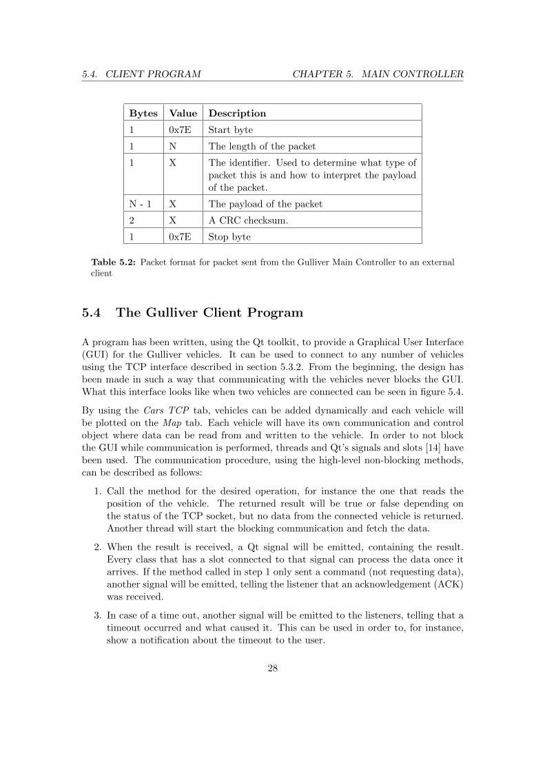
The main controller will always respond to packets received. When no data is expectedin the response an acknowledgement packet is sent back to confirm that the packet hasbeen received and processed; when data is expected a packet with the requested datawill be sent back. What the response packet looks like, sent from the main controller tothe external client, can be seen in table 5.2.
27
5.4. CLIENT PROGRAM CHAPTER 5. MAIN CONTROLLER
Bytes Value Description
1 0x7E Start byte
1 N The length of the packet
1 X The identifier. Used to determine what type ofpacket this is and how to interpret the payloadof the packet.
N - 1 X The payload of the packet
2 X A CRC checksum.
1 0x7E Stop byte
Table 5.2: Packet format for packet sent from the Gulliver Main Controller to an externalclient
5.4 The Gulliver Client Program
A program has been written, using the Qt toolkit, to provide a Graphical User Interface(GUI) for the Gulliver vehicles. It can be used to connect to any number of vehiclesusing the TCP interface described in section 5.3.2. From the beginning, the design hasbeen made in such a way that communicating with the vehicles never blocks the GUI.What this interface looks like when two vehicles are connected can be seen in figure 5.4.
By using the Cars TCP tab, vehicles can be added dynamically and each vehicle willbe plotted on the Map tab. Each vehicle will have its own communication and controlobject where data can be read from and written to the vehicle. In order to not blockthe GUI while communication is performed, threads and Qt’s signals and slots [14] havebeen used. The communication procedure, using the high-level non-blocking methods,can be described as follows:
1. Call the method for the desired operation, for instance the one that reads theposition of the vehicle. The returned result will be true or false depending onthe status of the TCP socket, but no data from the connected vehicle is returned.Another thread will start the blocking communication and fetch the data.
2. When the result is received, a Qt signal will be emitted, containing the result.Every class that has a slot connected to that signal can process the data once itarrives. If the method called in step 1 only sent a command (not requesting data),another signal will be emitted, telling the listener that an acknowledgement (ACK)was received.
3. In case of a time out, another signal will be emitted to the listeners, telling that atimeout occurred and what caused it. This can be used in order to, for instance,show a notification about the timeout to the user.
28

5.4. CLIENT PROGRAM CHAPTER 5. MAIN CONTROLLER
Figure 5.4: Two tabs with vehicle controls. More can be added with the Add Car button.
It should be noted that the map part of the program also has access to the interfaceobjects connected to the vehicles and can do everything that can be done from the tabs(the tabs are shown in figure 5.4) with some simple modifications if the people workingon the map editor decide to do so [4].
The connected Gulliver vehicles can also be maneuvered individually from a joystickfrom this program. Further, the interface can stream video from the vehicles in realtime if a camera is mounted and a server for video streaming is running.
29

6
A simple Traffic ScenarioApplication
With everything connected, a test of the system has been done with theMICAz motes connected to two vehicles. A simple scenario with two indi-vidual connected routes and two intersections, as shown in figure 6.1, hasbeen set up.
The MICAz motes did run a virtual traffic light with a certain schedule for each inter-section, shown as red areas in figure 6.1. The design of that schedule was not a part ofthis project, so the details will not be discussed here.
When the vehicles entered the intersection there were three things they could do, basedon the decision from the MICAz mote: continue on the same route, change lanes andcontinue on the other route or stop and wait for other vehicles to pass. This did work wellfor this scenario and the whole scenario could also be followed from the map editor/viewerin real time.
6.1 Suggested Improvements based on this Experiment
During this experiment, a few issues with the current platform were noted that could beimproved in the future, namely:
• The stop and go commands were not very smooth. When the decision from theMICAz was stop in the intersection, the vehicle would brake at full power. It wouldgive a better impression if a smooth slowdown was implemented.
30

6.1. SUGGESTED IMPROVEMENTS CHAPTER 6. TRAFFIC SCENARIO
Figure 6.1: Intersection scenario with two routes and two intersection areas
• The direction of the collision sensors should be combined with the current steeringangle of the vehicle. For instance, if the current steering angle is towards the leftand some obstacle is getting closer on the right side, it might not be necessary toslow down.
In other aspects, this experiment went very well and can be considered as successful.
31
7
Conclusions
The aim of this project was to participate in the construction of a miniaturevehicular platform with basic functionality to accept high level commands fornavigation (see chapter 1, section 1.1 for more details). The Gulliver vehiclesare now able to drive autonomously by carrying out simple high-level com-
mands provided from another platform, such as the SUMO simulator [7].
In the end, everything in the goals and even some additional features, such as the camerastream, was implemented. It can be concluded that the Gulliver vehicles now are a bitcloser to being useful in larger experiments as proposed in [1], however, there are manyareas left that could and should be improved in future projects.
7.1 Suggested Future Work
For future reference, the following improvements are suggested, based on the work ofthis project:
• A new main controller with a more powerful microcontroller should be created.Currently, only small routes can be stored (about 400 points) and there is nohardware floating point unit, making all floating point operations considerablyslower than fixed-point math.
• The algorithms for localization based on the Ranging and Communications Mod-ules (RCMs) should be improved, such that the angle of the vehicle is considered.Currently, only the compass is used to correct the angle, and it is very sensitive tometal and other disturbances that come close to the vehicle.
32
7.1. SUGGESTED FUTURE WORK CHAPTER 7. CONCLUSIONS
• Better algorithms for navigation should be written to handle more complex trafficsituations. For instance, currently there is no method to park the vehicle in a tightparking lot. A good reference for path-planning is [12], where a set of paths aregenerated and the one with the minimal cost based on a set of requirements ispicked.
• It would be useful if every vehicle was aware of the other vehicles that are closeby. Thereby, collision avoidance could be implemented based on localization inaddition to the current implementation based on the on-board sensors.
• More work should be spent on integrating the Gulliver vehicles with other systems.The current on-board communication interface is specifically made for the MICAzmotes and new commands are difficult to implement. Also, the client program (seesection 5.4) should provide an external interface to connect to other programs,such as the SUMO simulator [7], directly, without involving the MICAz motes.
33

Bibliography
[1] M. Pahlavan, M. Papatriantafilou, E. M. Schiller, Gulliver: a test-bed for develop-ing, demonstrating and prototyping vehicular systems, in: Proceedings of the 9thACM international symposium on Mobility management and wireless access, Mo-biWac ’11, ACM, New York, NY, USA, 2011, pp. 1–8.URL http://doi.acm.org/10.1145/2069131.2069133
[2] P. Kalden, E. Sterna, M. Tulldahl, M. Nilsson, N. Ilves, The gulliver car, Tech. rep.,Chalmers University of Technology (2012).
[3] A. Altby, T. Bostrom, T. Sibgatullin, K. Stjarne, Robusta och noggranna posi-tioneringssystem baserade pa avstandsmatningar mellan mobila noder, Tech. rep.,Chalmers University of Technology (2012).
[4] E. Dahlgren, J. Grunden, D. Gunnarson, N. Holtryd, A. Khazal, V. Swantesson, Enplattform for testning, utveckling och demonstration med hjalp av miniatyrfordon,Tech. rep., Chalmers University of Technology (2012).
[5] Time Domain, Application Programming Interface (API) Specification, PulsON 400RCM (2011).
[6] G. Welch, G. Bishop, An introduction to the kalman filter, Tech. rep., Universityof North Carolina at Chapel Hill (1997).
[7] M. Behrisch, L. Bieker, J. Erdmann, D. Krajzewicz, Sumo - simulation of urbanmobility: An overview, in: SIMUL 2011, The Third International Conference onAdvances in System Simulation, Barcelona, Spain, 2011, pp. 63–68.
[8] J. Shao, D. Nolan, M. Teissier, D. Swanson, A novel microcontroller-based sensorlessbrushless dc (bldc) motor drive for automotive fuel pumps, in: IEEE transactionson industry applications, Vol. 39, 2003.
[9] J. Shao, D. Nolan, T. Hopkins, A novel direct back emf detection for sensorlessbrushless dc (bldc) motor drives, in: STMicroelectronics Power Systems Applica-tions Lab, 2002.
34

BIBLIOGRAPHY BIBLIOGRAPHY
[10] T.-H. Kim, M. Ehsani, Sensorless control of the bldc motors from near-zero to highspeeds, in: IEEE transactions on power electronics, Vol. 19, 2004.
[11] I. Cox, Blanche-an experiment in guidance and navigation of an autonomous robotvehicle, Robotics and Automation, IEEE Transactions on 7 (2) (1991) 193 –204.
[12] Z. Shiller, Y.-R. Gwo, Dynamic motion planning of autonomous vehicles, in: IEEEtransactions on robotics and automation, Vol. 7, 1991.
[13] Q. Ni, W. Sun, X. Liang, Developing solaris gui application with gtk+, in: Informa-tion Science and Engineering (ICISE), 2009 1st International Conference on, 2009,pp. 3283 –3286.
[14] J. Blanchette, M. Summerfield, C++ gui programming with qt 4, 2nd Edition,Prentice Hall Press, Upper Saddle River, NJ, USA, 2008.
[15] J. Smart, K. Hock, S. Csomor, Cross-Platform GUI Programming with wxWidgets(Bruce Perens Open Source), Prentice Hall PTR, Upper Saddle River, NJ, USA,2005.
[16] Time Domain, Ultra Wideband Ranging and Communications Module, pulsON 400RCM (2011).
[17] Atmel Corporation, Sensorless control of 3-phase brushless DC motors, applicationnote AVR444 (2005).
[18] Microchip Technology Inc., dsPIC33F/PIC24H Family Reference Manual, Section14. Motor Control PWM (2010).
[19] R.-M. Jan, C.-S. Tseng, R.-J. Liu, Robust pid control design for permanent magnetsynchronous motor: A genetic approach, Tech. rep., Ming Hsin University of Scienceand Technology (2007).
[20] O. Montiel, R. Sepulveda, P. Melin, O. Castillo, M. Angel Porta, I. M. Meza,Performance of a simple tuned fuzzy controller and a pid controller on a dc motor,in: Proceedings of the 2007 IEEE Symposium on Foundations of ComputationalIntelligence, 2007.
[21] T. Wescott, Pid without a phd, in: Embedded Systems Programming, 2000.
[22] P. Koopman, T. Chakravarty, Cyclic redundancy code (crc) polynomial selectionfor embedded networks, in: The International Conference on Dependable Systemsand Networks, DSN-2004, 2004.
[23] M. Kam, X. Zhu, P. Kalata, Sensor fusion for mobile robot navigation, in: proceed-ings of the IEEE, Vol. 85, 1997.
[24] H. P. Moravec, Sensorfusion in certainty grids for mobile robot, in: AI Magazine,Vol. 9, 1988.
35

BIBLIOGRAPHY
[25] Y. Kanayama, B. I. Hartman, Smooth local path planning for autonomous vehicles,Tech. rep., University of California, Department of Computer Science (1989).
36
List of Figures
3.1 Location of the different components on the Gulliver vehicle. The 9-Degrees of Freedom sensor is not attached in this picture. It is located ona stick attached to the vehicle, so it can easily be seen on the real vehicle. 11
3.2 Overview of the control system on the vehicles . . . . . . . . . . . . . . . 123.3 The whole set-up with the Gulliver vehicles, the anchor RCMs and the
measured distances. . . . . . . . . . . . . . . . . . . . . . . . . . . . . . . 13
4.1 Resistor-Capacitor voltage divider/filter . . . . . . . . . . . . . . . . . . . 164.2 BEMF with mean value filter . . . . . . . . . . . . . . . . . . . . . . . . . 164.3 BEMF with median filter . . . . . . . . . . . . . . . . . . . . . . . . . . . 174.4 Commutation and angular speed . . . . . . . . . . . . . . . . . . . . . . . 18
5.1 External interface overview . . . . . . . . . . . . . . . . . . . . . . . . . . 215.2 Position definition . . . . . . . . . . . . . . . . . . . . . . . . . . . . . . . 215.3 Map example with two routes . . . . . . . . . . . . . . . . . . . . . . . . . 245.4 Vehicle control tabs . . . . . . . . . . . . . . . . . . . . . . . . . . . . . . 29
6.1 Intersection scenario . . . . . . . . . . . . . . . . . . . . . . . . . . . . . . 31
37
List of Tables
4.1 Packet format for motor controller . . . . . . . . . . . . . . . . . . . . . . 19
5.1 External-to-main controller packet format . . . . . . . . . . . . . . . . . . 275.2 Main controller-to-external packet format . . . . . . . . . . . . . . . . . . 28
38

Appendix A: The Gulliver Cara part of the Gulliver Project
Students
Peter Kaldén 870705-5136 [email protected] Sternå 880924-6930 [email protected] Ilves 900908-5637 [email protected] Tulldahl 901007-5977 [email protected] Nilsson 870918-5030 [email protected](Benjamin Vedder 871026-7090 [email protected])
Department of Computer Science and Engineering
Chalmers University of TechnologyGöteborg, Sweden 2011
6 juni 2012

Appendix A: Gulliver Car
Summary
This report details the design and construction of a small scale test platform for simulationof tra�c senarios. The platform is designed with a chassis from a remote controlled car as abase to approximate the behavior of a real car. On top of this base a system for controllingthe platform has been constructed with purpose designed circuitboards. These circuitboardsinterface with the car's various subsystems to for example enable it track to it's own positionand sense the distance to nearby objects. The car can also easily communicate with varioushost systems, such as a computer.
1

Appendix A: Gulliver Car
Sammanfattning
Den här rapporten behandlar designen och konstruktionen av en testplattform i liten skala försimulering av tra�ksituationer. Plattformen är designad med en radiostyrd bil som bas for attuppvisa beteende som liknar en riktig bil. På denna bas har ett specialdesignat kontrollsystembyggts som kontrollerar bilens undersystem. Dessa undersystem möjliggör bilen att t.ex. spårasin egen position i förhållande till omgivning och känna av avståndet till närliggande objekt.
2
Appendix A: Gulliver Car INNEHÅLL
Innehåll
1 Inledning 5
2 Designmål 6
2.1 Mekaniska konsiderationer . . . . . . . . . . . . . . . . . . . . . . . . . . . . . . 62.2 Elektriska konsiderationer . . . . . . . . . . . . . . . . . . . . . . . . . . . . . . 6
3 Mekanisk Konstruktion 7
3.1 Chassimodi�kationer . . . . . . . . . . . . . . . . . . . . . . . . . . . . . . . . . 73.2 Motor . . . . . . . . . . . . . . . . . . . . . . . . . . . . . . . . . . . . . . . . . 83.3 Stryservo . . . . . . . . . . . . . . . . . . . . . . . . . . . . . . . . . . . . . . . 8
4 Sensorer 9
4.1 Omgivningsensorer . . . . . . . . . . . . . . . . . . . . . . . . . . . . . . . . . . 94.1.1 Val av ultraljudsensor . . . . . . . . . . . . . . . . . . . . . . . . . . . . 94.1.2 Val av infraröd sensor . . . . . . . . . . . . . . . . . . . . . . . . . . . . 9
4.2 Odemetri . . . . . . . . . . . . . . . . . . . . . . . . . . . . . . . . . . . . . . . 104.2.1 Val av Odemetrisensorer . . . . . . . . . . . . . . . . . . . . . . . . . . . 10
4.3 Positionering . . . . . . . . . . . . . . . . . . . . . . . . . . . . . . . . . . . . . 104.3.1 Val av positioneringssensor . . . . . . . . . . . . . . . . . . . . . . . . . 11
4.4 Riktningssensor . . . . . . . . . . . . . . . . . . . . . . . . . . . . . . . . . . . . 114.4.1 Val av riktningssensor . . . . . . . . . . . . . . . . . . . . . . . . . . . . 11
5 Elektrisk konstruktion 12
5.1 Motorkontroller . . . . . . . . . . . . . . . . . . . . . . . . . . . . . . . . . . . . 125.2 9-DOF-sensor . . . . . . . . . . . . . . . . . . . . . . . . . . . . . . . . . . . . . 125.3 Distanssensorkort . . . . . . . . . . . . . . . . . . . . . . . . . . . . . . . . . . . 125.4 P400 RCM . . . . . . . . . . . . . . . . . . . . . . . . . . . . . . . . . . . . . . 125.5 Interface-kort . . . . . . . . . . . . . . . . . . . . . . . . . . . . . . . . . . . . . 125.6 Huvudkort . . . . . . . . . . . . . . . . . . . . . . . . . . . . . . . . . . . . . . . 12
6 Mjukvara 14
6.1 Motorkontroller . . . . . . . . . . . . . . . . . . . . . . . . . . . . . . . . . . . . 146.2 9-DOF-sensor . . . . . . . . . . . . . . . . . . . . . . . . . . . . . . . . . . . . . 146.3 Distanssensorkort . . . . . . . . . . . . . . . . . . . . . . . . . . . . . . . . . . . 146.4 Interface-kort . . . . . . . . . . . . . . . . . . . . . . . . . . . . . . . . . . . . . 146.5 Huvudkortet . . . . . . . . . . . . . . . . . . . . . . . . . . . . . . . . . . . . . . 14
6.5.1 RCM-kommunikation . . . . . . . . . . . . . . . . . . . . . . . . . . . . 156.5.2 Styrkommandon . . . . . . . . . . . . . . . . . . . . . . . . . . . . . . . 15
7 Avslutning 16
7.1 Resultat . . . . . . . . . . . . . . . . . . . . . . . . . . . . . . . . . . . . . . . . 167.2 Diskussion och förbättringsmöjligheter . . . . . . . . . . . . . . . . . . . . . . . 167.3 Re�ektioner på gruppen . . . . . . . . . . . . . . . . . . . . . . . . . . . . . . . 17
3

Appendix A: Gulliver Car INNEHÅLL
Tack
Flera person har hjälpt oss under projektets gång och vi har varit glada för att fått arbetatillsammans med så många kompetenta personer. Vi vill, utöver att tacka dessa, även speciellttacka följande personer.
� Benjamin Vedder
� Elad Schiller
� Mitra Pahlavan
� Roger Johansson
� Henk Wymeers
� Gabriel Garcia
� Amir Tohidi
� Mohamed Mustafa
4

Appendix A: Gulliver Car 1 INLEDNING
1 Inledning
Dagens bilar rör sig allt mer mot automatisering, med system som tex automatiskt bromsareller väger undan om du håller på att krocka, system som upptäcker djur på vägen och systemså ser håller dig mitt i �len och märker när då håller på att somna. Någon gång inom en inteallt för snar framtid så kommer det �nnas helautomatiserade bilar. För att bana väg för detbehöver det �nnas e�ektiva sätt att kontrollera tra�k�öden. Det går förstås att simulera i endator, men då det �nns så många faktorer så är det svårt att helt förstå alla situationer utanatt veri�era simulationerna i verkligheten. Dock så är det dyrt och omständligt att veri�era ifull skala och det är här Gulliver är tänkt att komma in, som en testplattform som enkelt kananvända för att veri�era simulationer utan att behöva göra en fullskalig veri�ering.
5

Appendix A: Gulliver Car 2 DESIGNMÅL
2 Designmål
Då det är tänkt att Gulliver skall bete sig liknande en vanlig bil behövs en mekanisk struktursom möjliggör ett liknande beteende. Samtidigt krävs ett elektriskt system som kan kontrollerade mekaniska delarna på ett sätt som ger det beteende som eftersöks. Vidare krävs ocksååterkoppling i form av sensorer så att bilen själv kan kontrolleras mer precist och ha enreferens till de instruktioner som den får.
2.1 Mekaniska konsiderationer
Då en bils möjliga beteende är relativt begränsat så krävs det inte mycket mer än en motorför att åka framåt och bakåt samt en motor för att svänga. Dock är är det en fördel meddämpning och fjädring då dessa kan göra konstruktionen mer stabil och öka dess livslängd.Den mekaniska konstruktionen är dock inte avsedd att simulera de fysiska delarna av en bilutan snarare mer konceptet.
2.2 Elektriska konsiderationer
Det elektriska kontrollsystemet kräver mer ingående konsiderationer, då det måste kunnakänna av omgivningen och dess egna absoluta position. Dessutom måste det även kunna kon-trollera det mekaniska delarna att kunna följa de instruktioner som bilen får. Figur 2.1 visarden föreslagna topologin för det elektriska systemet.
9 DOF sensorDOF = Degrees of Freedom
AdapterMultiUART
MultiUART
Distance sensors
MultiUART
MultiUART
MultiUART
Main board
RF FTDI(USB-to-UART)
UART(for Display)
UART(for MC)
Motor controller
UART
Sensors:
Display(optional)
UART
Computer(optional)
FTDI(USB on computer)
Optional devices:
RF FTDI(USB-to-UART)
Bluetooth
Interface board
Servo(for steering)
UA
RT
(for
RC
M)
P400 RCM(Localization Board)
UART
P400 RCM(Anchor)
Motor
Figur 2.1: Topologin
De gröna linjerna symboliserar en fysisk kontakt mellan två moduler, de prickade blåa linjernarepresenterar trådlös kommunikation och lådorna på modulerna visar vilket protokoll somanvänds.
6

Appendix A: Gulliver Car 3 MEKANISK KONSTRUKTION
3 Mekanisk Konstruktion
Att konstruera ett eget chassi ansågs vara allt för tidskrävande så därför valdes ett chassi tillen radiostyrd bil ut till som chassi. Detta gav en bas som uppfyllde många av plattformensmekaniska krav. Chassit som valdes var av typ OFNA Dirt Electric. Det hade stötdämpareoch fjädring på samtliga hjul, anpassad infästning för en elektrisk motor och ett styrservo ochanlände 80 procent förkonstruerat. Figur 3.1 visar chassit när det är fullt hopsatt och styrservooch motor är monterat.
Figur 3.1: Bilen utan egna plastdetaljer
3.1 Chassimodi�kationer
Då chassit saknade bra yta för att montera elektroniken behövdes det byggas en sådan yta.För att denna skulle bli korrekt och för att kunna bedöma olika möjliga lösningar så gjordesen CAD-modell av chassit varefter en plattform i �era delar designades till chassit. Dessutomså designades en roll-bar för att skydda elektroniken och även fästen till sensorerna som lättkunde riktas om och placeras på �era olika ställen på plattformen. Figur ?? visar den färdigadesignen CAD-modellen, notera sensorfästena (blå på bilden), plattformen (röd på bilden) ochrollbaren (grön på bilden). Dessa delar tillverkades sedan i en CNC-fräs alternativt laserskärareutifrån deras respektive CAD-modeller.
7
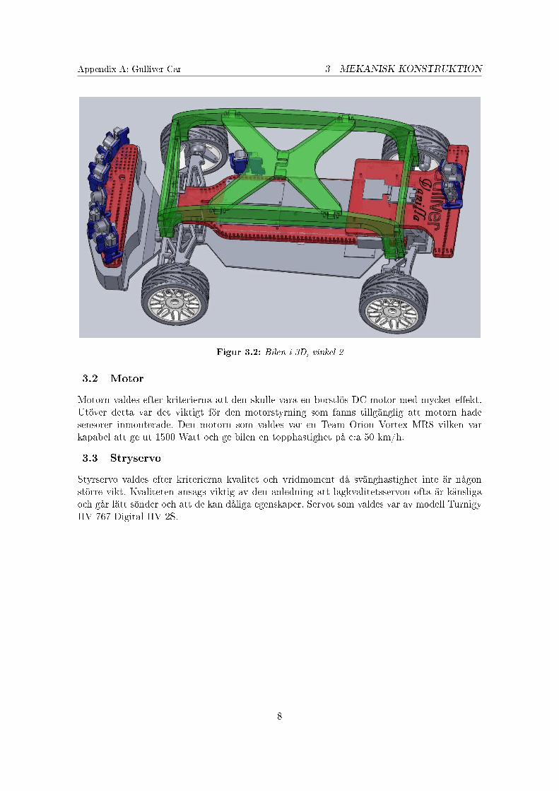
Appendix A: Gulliver Car 3 MEKANISK KONSTRUKTION
Figur 3.2: Bilen i 3D, vinkel 2
3.2 Motor
Motorn valdes efter kriterierna att den skulle vara en borstlös DC-motor med mycket e�ekt.Utöver detta var det viktigt för den motorstyrning som fanns tillgänglig att motorn hadesensorer inmonterade. Den motorn som valdes var en Team Orion Vortex MR8 vilken varkapabel att ge ut 1500 Watt och ge bilen en topphastighet på c:a 50 km/h.
3.3 Stryservo
Styrservo valdes efter kriterierna kvalitet och vridmoment då svänghastighet inte är någonstörre vikt. Kvaliteten ansågs viktig av den anledning att lågkvalitetsservon ofta är känsligaoch går lätt sönder och att de kan dåliga egenskaper. Servot som valdes var av modell TurnigyHV-767 Digital HV-2S.
8

Appendix A: Gulliver Car 4 SENSORER
4 Sensorer
Det elektriska systemet designades efter de sensorer som valdes ut för att kunna fullfölja dekrav som ställdes framförallt på positioneringen men även på möjlighet att känna omgivningen.De sensorer som valdes var följande.
4.1 Omgivningsensorer
För att upptäcka omgivande objekt hade en laserscanner varit ideal då denna kan scannanästan 360 grader samtidigt med en modul. Denna �ck dock väljas bort då den var utanförbudgeten. Istället valdes en kombination av ultraljud och infraröda sensorer, detta då dessakompletterar varandra bra och i tillräcklig mängd kan ge liknande funktion som en laserscannerskulle ge.
4.1.1 Val av ultraljudsensor
De ultraljudssensorer som valdes ut var av typen Ultrasonic Ranger SRF08 och de fungerarhelt enkelt så att de skickar ut en ljudpuls och mäter tiden till att re�ektionen kommer tillbakatill sensorn. Genom att mäta tiden tills ekot kommer tillbaka och baserat på ljudets hastighetså kan sensorn ta reda på avståndet till det objekt som re�ekterade ljudet. Det �nns ett paraspekter att tänka på då dessa sensorer används. Delvis kan ultraljudssensorerna regera påandra sensorers pulser ifall de sitter på ett sådant sätt och om de mäter för tätt, vilket skulleinnebära att de kan rapportera felaktig mätdata. Dessutom har de en bred mätkon vilketlämpar sig mer för att upptäcka hinder snarare än att mer precist mäta avståndet till någotvälkänt objekt. Fördelen med ljudsensorer är även att de är färgoberoende, till skillnad frånmånga ljusbaserad sensorer som kan ha svårt att se svarta objekt.
Figur 4.1: Ultraljudssensor, SRF08
4.1.2 Val av infraröd sensor
De infraröda (IR) sensorer som valdes ut är av tillverkad av SHARP och är analoga avståndssen-sorer som med hjälp av triangulering kan mäta avståndet till objekt. De skickar ut en infrarödljusstråle som re�ekteras av objekt och sedan mäter sensorn infallsvinkeln på ljuset och tarmed hjälpa av triangulering fram avståndet till objektet. Två olika modeller av denna sensorvaldes: GP2Y0D21YK, som mäter avstånd mellan 10 och 80 cm, samt GP2Y0A02YK, sommäter avstånd mellan 20 och 150 cm. Dessa sensorer är mer lämpade att mäta avstånd tillstörre objekt då de har en mätstråle snarare än en mätkon vilket gör att de inte påverkasav andra närliggande objekt. Dessa sensorer har även en stor fördel gentemot många andraljusbaserade sensorer som innebär att de är nästan färgoberoende (då de använder sig avtriangulering).
9
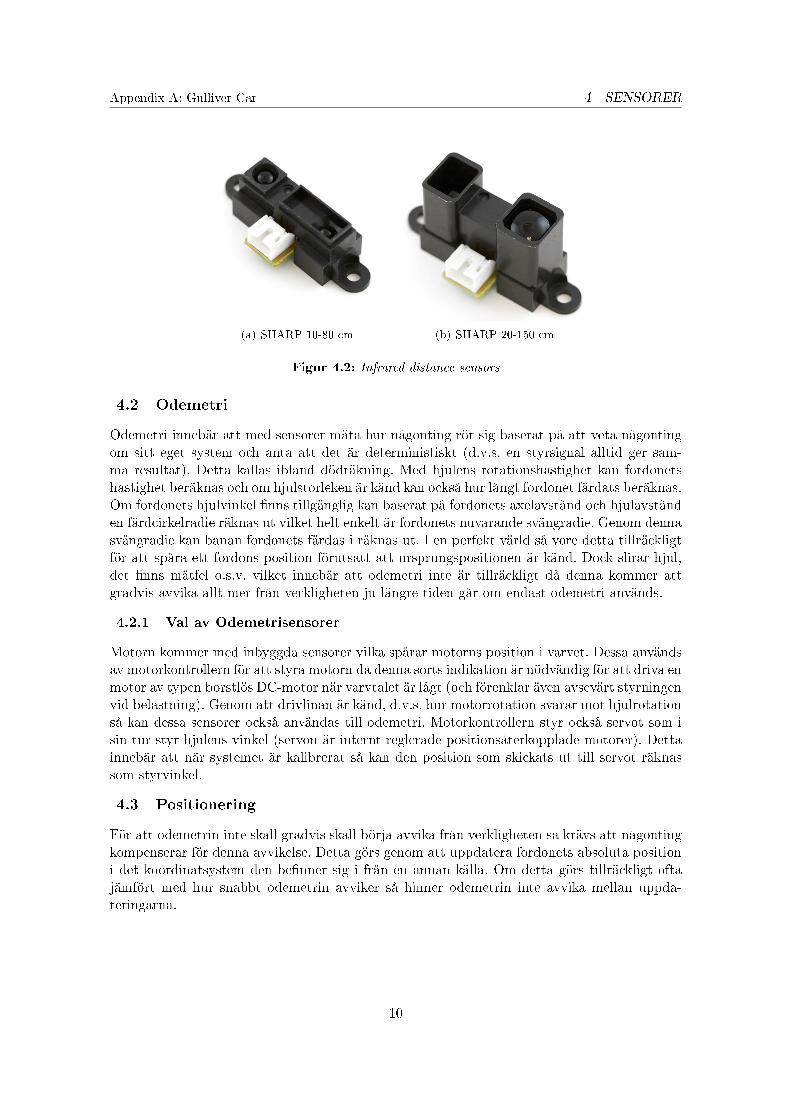
Appendix A: Gulliver Car 4 SENSORER
(a) SHARP 10-80 cm (b) SHARP 20-150 cm
Figur 4.2: Infrared distance sensors
4.2 Odemetri
Odemetri innebär att med sensorer mäta hur någonting rör sig baserat på att veta någontingom sitt eget system och anta att det är deterministiskt (d.v.s. en styrsignal alltid ger sam-ma resultat). Detta kallas ibland dödräkning. Med hjulens rotationshastighet kan fordonetshastighet beräknas och om hjulstorleken är känd kan också hur långt fordonet färdats beräknas.Om fordonets hjulvinkel �nns tillgänglig kan baserat på fordonets axelavstånd och hjulavstånden färdcirkelradie räknas ut vilket helt enkelt är fordonets nuvarande svängradie. Genom dennasvängradie kan banan fordonets färdas i räknas ut. I en perfekt värld så vore detta tillräckligtför att spåra ett fordons position förutsatt att ursprungspositionen är känd. Dock slirar hjul,det �nns mätfel o.s.v. vilket innebär att odemetri inte är tillräckligt då denna kommer attgradvis avvika allt mer från verkligheten ju längre tiden går om endast odemetri används.
4.2.1 Val av Odemetrisensorer
Motorn kommer med inbyggda sensorer vilka spårar motorns position i varvet. Dessa användsav motorkontrollern för att styra motorn då denna sorts indikation är nödvändig för att driva enmotor av typen borstlös DC-motor när varvtalet är lågt (och förenklar även avsevärt styrningenvid belastning). Genom att drivlinan är känd, d.v.s. hur motorrotation svarar mot hjulrotationså kan dessa sensorer också användas till odemetri. Motorkontrollern styr också servot som isin tur styr hjulens vinkel (servon är internt reglerade positionsåterkopplade motorer). Dettainnebär att när systemet är kalibrerat så kan den position som skickats ut till servot räknassom styrvinkel.
4.3 Positionering
För att odemetrin inte skall gradvis skall börja avvika från verkligheten så krävs att någontingkompenserar för denna avvikelse. Detta görs genom att uppdatera fordonets absoluta positioni det koordinatsystem den be�nner sig i från en annan källa. Om detta görs tillräckligt oftajämfört med hur snabbt odemetrin avviker så hinner odemetrin inte avvika mellan uppda-teringarna.
10
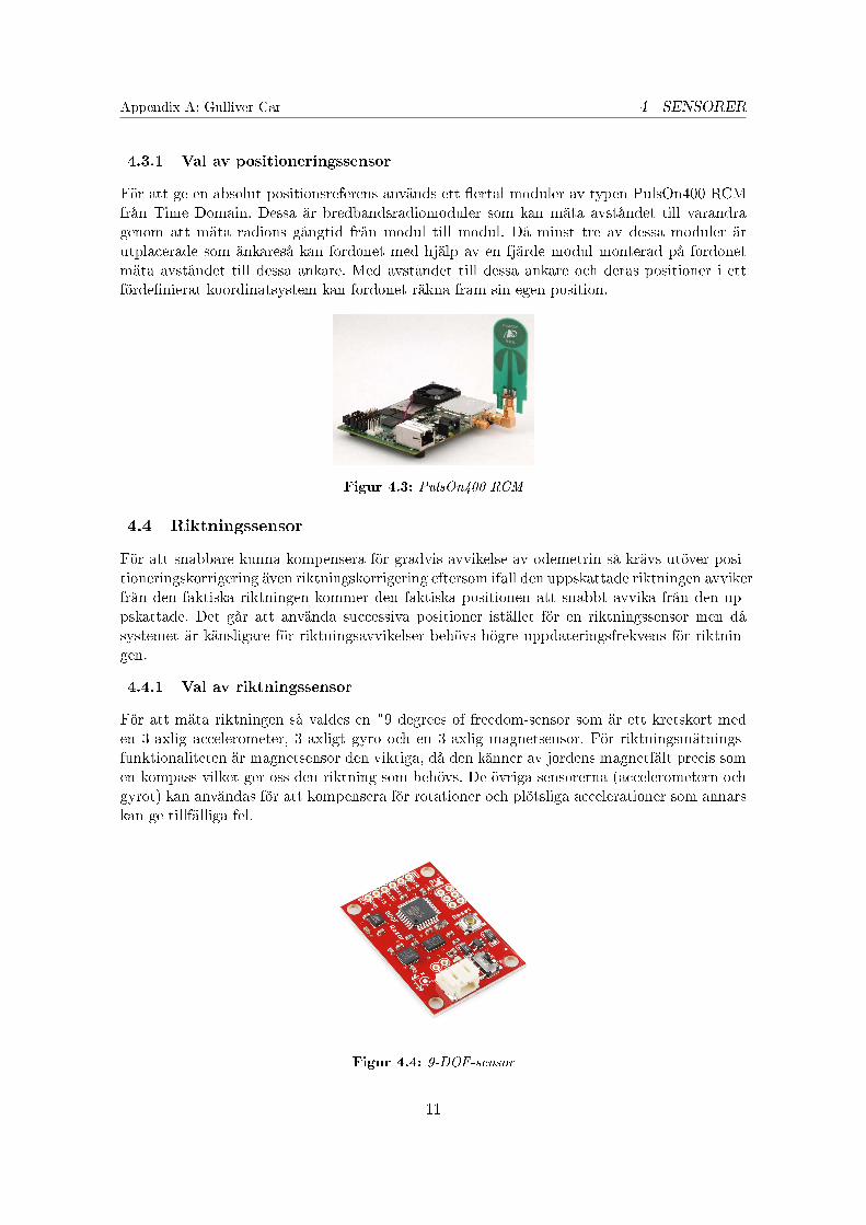
Appendix A: Gulliver Car 4 SENSORER
4.3.1 Val av positioneringssensor
För att ge en absolut positionsreferens används ett �ertal moduler av typen PulsOn400 RCMfrån Time Domain. Dessa är bredbandsradiomoduler som kan mäta avståndet till varandragenom att mäta radions gångtid från modul till modul. Då minst tre av dessa moduler ärutplacerade som änkareså kan fordonet med hjälp av en fjärde modul monterad på fordonetmäta avståndet till dessa ankare. Med avståndet till dessa ankare och deras positioner i ettförde�nierat koordinatsystem kan fordonet räkna fram sin egen position.
Figur 4.3: PulsOn400 RCM
4.4 Riktningssensor
För att snabbare kunna kompensera för gradvis avvikelse av odemetrin så krävs utöver posi-tioneringskorrigering även riktningskorrigering eftersom ifall den uppskattade riktningen avvikerfrån den faktiska riktningen kommer den faktiska positionen att snabbt avvika från den up-pskattade. Det går att använda successiva positioner istället för en riktningssensor men dåsystemet är känsligare för riktningsavvikelser behövs högre uppdateringsfrekvens för riktnin-gen.
4.4.1 Val av riktningssensor
För att mäta riktningen så valdes en "9 degrees of freedom-sensor som är ett kretskort meden 3-axlig accelerometer, 3-axligt gyro och en 3-axlig magnetsensor. För riktningsmätnings-funktionaliteten är magnetsensor den viktiga, då den känner av jordens magnetfält precis somen kompass vilket ger oss den riktning som behövs. De övriga sensorerna (accelerometern ochgyrot) kan användas för att kompensera för rotationer och plötsliga accelerationer som annarskan ge tillfälliga fel.
Figur 4.4: 9-DOF-sensor
11
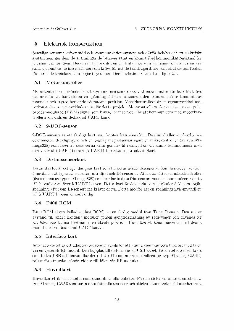
Appendix A: Gulliver Car 5 ELEKTRISK KONSTRUKTION
5 Elektrisk konstruktion
Samtliga sensorer kräver stöd och kommunikationssystem och därför behövs det ett elektrisktsystem som ger dem de spänningar de behöver samt en kompatibel kommunikationskanal föratt sända datan över. Dessutom behövs det en central enhet som kan samordna alla sensorersamt genomföra de instruktioner som krävs för att de tra�kalgoritmer som skall testas. Nedanförklaras de kretskort som ingår i systemet. Deras relationer beskrivs i �gur 2.1.
5.1 Motorkontroller
Motorkontrollern används för att styra motorn samt servot. Eftersom motorn är borstlös krävsdet mer än att bara skicka en spänning till den så snurrar den. Motorn måste kommuterasmanuellt och styras beroende på rotorns position. Motorkontrollern är en egenutvecklad mo-torkontroller som utvecklades utanför detta projekt. Motorontrollern skickar även ut en puls-breddsmodulerad (PWM) signal som kontrollerar servot. För att kommunicera med motorkon-trollern används en dedikerad UART-kanal.
5.2 9-DOF-sensor
9-DOF-sensorn är ett färdigt kort som köptes från sparkfun. Den innehåller en 3-axlig ac-celerometer, 3-axligt gyro och en 3-axlig magnetsensor samt en mikrokontroller (av typ AT-mega328) som läser av sensorerna samt gör lite �ltrering. För att kunna kommunicera medden via Multi-UART-bussen (MUART) tillverkades ett adapterkort.
5.3 Distanssensorkort
Distanskortet är ett egendesignat kort som hanterar avståndssensorer. Som beskrevs i sektion4 används två typer av sensorer: ultraljud och IR-sensorer. På kortet sitter en mikrokontroller(även denna av typen ATmega328) som samlar in data från sensorerna och kommunicerar dettatill huvudkortet över MUART-bussen. Detta kort är det enda som använder 5 V som logik-spänning, eftersom IR-sensorerna kräver detta. Detta medför att en spänningsnivåomvandlaretill MUART-bussen är nödvändig.
5.4 P400 RCM
P400 RCM (även kallad endast RCM) är en färdig modul från Time Domain. Den mäteravstånd till andra likadana moduler genom gångtidsmätning av radiovågor och används föratt bilen ska kunna bestämma en absolutposition. Huvudkortet kommunicerar med dennamodul med en dedikerad UART-kanal.
5.5 Interface-kort
Interface-kortet är ett adapterkort som används för att kunna kommunicera trådlöst med bilenvia en generisk RF-modul. Den kopplas till datorn via en USB-kabel. På kortet sitter en kretssom tolkar USB och omvandlar det till UART som mikrokontrollern (av typ ATxmega32A4U)tolkar för att sedan sända vidare till bilen via RF-modulen.
5.6 Huvudkort
Huvudkortet är den modul som samordnar alla enheter. På den sitter en mikrokontroller avtyp ATxmega128A3 som tar in data från alla sensorer och skickar kommandon till utenheterna.
12
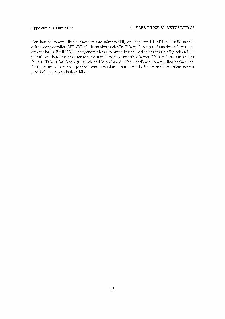
Appendix A: Gulliver Car 5 ELEKTRISK KONSTRUKTION
Den har de kommunikationskanaler som nämnts tidigare; dedikerad UART till RCM-moduloch motorkontroller; MUART till distanskort och 9DOF-kort. Dessutom �nns det en krets somomvandlar USB till UART därigenom direkt kommunikation med en dator är möjlig och en RF-modul som kan användas för att kommunicera med interface-kortet. Utöver detta �nns platsför ett SD-kort för datalagring och en blåtandsmodul för ytterligare kommunikationskanaler.Slutligen �nns även en dipswitch som användaren kan använda för att ställa in bilens adressmed ifall det används �era bilar.
13

Appendix A: Gulliver Car 6 MJUKVARA
6 Mjukvara
För att kunna utnyttja bilens funktioner krävs en stor mängd mjukvara. Varje kort har sinegen mjukvara. I denna del behandlas endast den helt eller delvis egenproducerade mjukvaran.
6.1 Motorkontroller
Mjukvaran i motorkontrollern är utanför ramen för detta projekt, men i korthet så mäter denpositionen på motorn och beroende på detta skickar signaler till motorn så att den roterar. Deninnehåller även en PID-regulator så att den alltid försöker hålla samma hastighet oavsett lastpå motorn. Vidare kontrollerar den styrservot med PWM-styrning. Den mäter kontinuerligtmotorns rotationshastighet, motorns temperatur, sin egen temperatur samt batterispänningenpå både logikbatteriet och motorbatteriet. Den tar emot kommandon från huvudkortet viaUART. Den tar emot kommandon såsom hastighet och riktning på motorn samt position påservot och kan dessutom rapportera tillbaka all sin data till huvudkortet.
6.2 9-DOF-sensor
9-DOF-sensorn samlar in data från accelerometern, gyrot och magnetometern. Mikrokon-trollern kommunicerar med de tre sensorerna med hjälp av I2C. Den har även stöd för kali-brering som går till så att extremvärdena noteras och därefter räknas det slutliga värdet förvarje sensor utifrån detta. Detta är nödvändigt då varje sensor är individuell från fabrik. Varjesensor har även inbyggd viss �ltrering (lågpass�lter).
6.3 Distanssensorkort
Distanssensorkortet samlar in data från distanssensorerna. Ultraljudssensorerna kommunicerastill via I2C och för att öka samplingshastigheten utan att riskera att sensorerna stör varandrautförs mätningar på fysiskt motstående sensorer samtidigt. Ultraljudssensorerna rapporterarsitt avstånd direkt i cm. IR-sensorernas avstånd ges ut i en analog spännings och avläses medden inbyggda analog-till-digital-omvandlaren (ADC). Värdet som sensorerna ger ut omvandlastill avstånd med hjälp av en look-up-tabell för att avlasta processorn, då den division som krävsskulle innebära mycket jobb för den.
6.4 Interface-kort
Interface-kortet är ett adapterkort som används för att kunna kommunicera trådlöst med bilenvia en generisk RF-modul. Den får via USB-UART-omvandlaren in kommandon från datornseriellt via UART som den sedan vidarebefordrar via SPI till RF-modulen som sedan sänderut detta. Den kan även ta emot data från bilen via RF-modulen och skicka tillbaka den tilldatorn.
6.5 Huvudkortet
Här implementerades funktioner för grundläggande kommunikation till alla enheterna samtgrundläggande styrfunktioner såsom kör- och styrkommandon. Som tidigare nämnts kommu-nicerar den med alla de andra korten, främst via UART (antingen dedikerad eller via MUART-bussen), samt även med SD-kortet och bilens RF-modul via SPI. Mjukvaran i huvudkortet ärmycket omfattande och kommer därför bara att beskrivas kort.
14

Appendix A: Gulliver Car 6 MJUKVARA
6.5.1 RCM-kommunikation
För att kommunicera med RCMen används en paketstruktur. Paketet innehåller en header somanvänds för synkronisering, längd på meddelandet, kommando, meddelande-ID och slutligenen CRC (cyclic redundancy check, används för att kontrollera att meddelandet kommer framkorrekt). Allt detta byggs i förväg upp och skickas sedan till RCM-modulen. RCM-modulensvarar sedan med det man bad om, t.ex. avståndet till en annan RCM med en viss adress.Huvudprocessorn ber bilens RCM att mäta avstånd till var och en ankar-RCMerna och räknarbaserat på detta ut bilens position givet ankarnas positioner i det förde�nierade koordinatsys-temet.
6.5.2 Styrkommandon
Förutom de enklare "kör-, stanna- och sväng-kommando kan bilen även göra en del meravancerade kommandon. En av de grundläggande byggstenarna i mer avancerade användar-funktioner är kommandot "kör till en punkt i koordinatsystemet". Detta kommando användersig utav odemetrin som den väger samman med positionen från RCMen och riktningen från9-DOFen. Baserat på sin egen position och riktning räknar den ut en cirkelbåge som den kanköra för att komma till den angivna punkten. Detta innebär att algoritmen producerar väldigtvida svängar när målet är långt borta och skarpa svängar nära målet. För att sträckan inte skabli onödigt lång och indirekt vid mål långt borta, skalas styrvinkeln med avståndet till målet,vilket gör att den fort svänger åt rätt håll för att sedan åka ganska rakt mot målet. Genom attatt sekventiellt koppla samman ett �ertal "kör till en punkt-kommandon kan man få bilen attköra en bana. Eftersom det kan vara svårt att trä�a en punkt exakt har bilen en del funktionerför att åtgärda detta. Den har en viss tolerans-zonrunt varje punkt som innebär att om bilenkommer innanför denna zon räknas den är framme vid punkten och kan börja gå mot nästa.Den kan även "övergepunkter som den tycker är för svåra att komma till och fortsätta direkttill nästa. Med hjälp av dessa grundstenar kan användaren bygga sin applikation för att fåbilen att göra ännu mer avancerade saker och med hjälp av detta testa sina scenarion.
15

Appendix A: Gulliver Car 7 AVSLUTNING
7 Avslutning
7.1 Resultat
Gruppen lyckades under projektet att ta fram en fungerade bil som kan navigera i ett rumoch analysera sin omgivning. Bilen som togs fram är �exibel och robust med goda möjlighetertill utbyggnad både vad gäller hårdvara och mjukvara. Det är enkelt att kommunicera medbilen från en dator, då det �nns �era sätt att göra detta på, samt att bilen innehåller endel kommandon på lite högre nivå förutom de mest grundläggande funktionerna. Det är ävenenkelt att få ut information om bilens status, t.ex. hastighet, position och sensordata som kananvändas för t.ex. visualisering av bilen och felsökning.
7.2 Diskussion och förbättringsmöjligheter
Generellt sett ser vi projektet som en lyckat projekt. Dock �nns det en del utvecklingsmöj-ligheter för framtiden. Det är dock självklart upp till användaren att de�niera vad dennabehöver. Nedan följer exempel på saker som kan förbättras samt förslag för fortsatt utveck-ling:
� Mjukvaran skulle kunna vara mer strukturerad och enklare att förstå. Som det är nufungerar den väldigt bra och är väl optimerad. Med detta följer som de �esta som jobbatmed programmering förstår att den samtidigt är ganska svår att sätta sig in i för attgöra några större ändringar.
� Bättre integrering och användning av avståndssensorer skulle vara bra. Detta är docknågonting som skulle bero på vilken applikation som bilen skulle användas till och skullevara upp till användaren att designa. Som det är nu har bilen endast mycket enklafunktioner för att vara en sista utväg ifall den skulle vara på väg att krocka.
� Integration av �er av sensorerna från 9-DOFen är någonting som funderats mycket på un-der projektets gång. När bilen testats har den främst körts ganska långsamt. Accelerom-etern och gyrot är sensorer som lämpar sig bra för korrigering av plötsliga förändringar.Dock skulle integration av dessa sensorer kunna förbättra dödräkningen avsevärt.
� Mjukvara för datorn är någonting som inte är inom detta projekts ram, men någontingsom skulle vara nödvändigt för fortsatt utveckling. Sådant är även nödvändigt vid ko-ordinering av �era fordon.
� Hitta en billigare lösning för positioneringen är nödvändigt för att hålla priset nere. EnRCM-modul kostar mer än resten av bilen. Detta är dock svårt att lösa till ett billigtpris med samma prestanda som RCMerna ger. Vid ett större system utomhus skullevanlig GPS kunna användas, men för denna bil skulle detta innebära alldeles för dåligupplösning och uppdateringshastighet.
� En annan lösning för den trådlösa kommunikationen till bilen vore bra. Eftersom RF-modulerna som används inte är extremt robusta händer det att datorn ibland tapparkontakt med bilen. Bluetooth eller WLAN skulle kunna användas komplementärt tillRF-modulen för att uppnå högre robusthet.
16

Appendix A: Gulliver Car 7 AVSLUTNING
7.3 Re�ektioner på gruppen
Vi har haft mycket nytta av den spridda expertis som fanns inom projektgruppen. Detta varbra på många sätt, och vi nyttjade de olika personernas förmågor väl, anser vi. Vissa av oss varmycket duktiga på elektronik, andra på CAD och några på organisation av projektet. Dock ärdet av högsta vikt att en teknisk grund och förståelse om elektronik, mekanik och datorteknik,något alla deltagare hade. Denna grundkunskap behövs för att alla deltagare skall kunna påett bra sätt diskutera design och upplägg av bilen och dess system samt kunna förstå problemoch vad problemen innebär vid diskussioner med personer i gruppen och utanför gruppen.
17