Embed Size (px)
Citation preview

Gullfaks Subsea Compression
Subsea Installation with monohull vessels - Pushing the limits
Amund Moen, 6 August 2015

2
Introduction – Subsea 7
The Gullfaks Subsea Compression project
Working with existing subsea structures
Module installation
Marine operations

3
A world leading seabed to surface partner

4 seabed-to-surface4 seabed-to-surface4
Subsea 7 provide technical solutions to enable the delivery of complex projects

5 seabed-to-surface5 seabed-to-surface5
The Gullfaks Compression project

6
Increasing the recoverable reserves from Gullfaks...

7
Why Subsea Processing?

8
Existing field lay out

9
• Project management, Engineering & Planning of the work– Installation engineering & interfaces
– development & modification of equipment/vessel to enable installation and future intervention
– Detailed design of layout, spools, covers
• Procurement/Subcontracting– Mattresses, big bags, dredging, cutting, etc
• Fabrication – Spools & covers
– Installation aids, spreader bars
• Installation/marine operations– Preparations (dredging, removal, modification), Wet Gas Compressor
(WGC), IPSU, spools, covers, tie- in, RFO, etc
Contract for Marine Operations was awarded 2012

10
Contract for Marine Operations awarded 2012
• Company Provided Item’s– Hubs and tie in systems – FMC, OneSubsea & Subsea 7
– Wet Gas Compressor – OneSubsea
– Intergrated Power and Service Umbilical (IPSU) –Nexans
– Rock dumping

11
Using the right tool for the right job
Seven Viking: WGC module installation
Skandi Acergy: Spools, covers and WGC hatches
Oleg Strashnov: Wet Gas Compression protection structure and compression station
Normand Oceanic: Integrated Power and Service Umbilical installation, incl UTA
Acergy Viking: preparation work, survey & dredging
Havila Subsea: Removal of existing structures, tie in & precommissioning
12 seabed-to-surface12 seabed-to-surface12
Working with existing subsea structures

13
Brown field challenges...
• Hub capacities and spool design– Little documentation available for existing
hub capacities
– Field layout consist of a very congested area where not much flexibility is allowed for spool size optimization
– Manifold manufacturer performed extensive documentation work for hub-capacities of existing templates
– Reduced hub capacities 60%, due to HISC
– Spools grew in size and all spare bends used to soften spools
– UTIS tool rebuilt to allow for stroke-bending mitigated spools
– Complex installation with tilting and airbags
Old layout
New layout
Old layout

14
Brown field challenges...
• Requires new thinking on GRP covers design– GRP concept with grating and sand-filled
stiffening beams developed
– Cost effective solution which allows for fabrication of large covers that traditionally would not be feasible to install
– Due to the ventilation given by grating, thedesign allows for horizontal installation
– Installation possible in Hs>2.5m
– Reduced installation time due to reduction in amount of covers
– Dropped object tests was performed on cover (50kJ) with no delamination/deformation

15
Testing of new cover design
• Conservative approach: – 1,5 tons
– 6 m height
– 12 m GRP beam

16
• Removal of rock, schedule uncertainties– Rock size varies
– Drill cuttings
– Hardness of soil
– Height of different layers
– Handling of hoses, rock removed 50 m away...
Brown field challenges...
X-Subsea (Scanmachine)

17 seabed-to-surface17 seabed-to-surface17
WGC Module installation

18
Seven Viking - capacity
• Statoil IMR

19
Seven Viking - capacity
• Module Handling System (MHS) data:– 70Te WLL winch (main winch)
– 20Te WLL winch (auxiliary winch)
– 3-off Guide Wires (WLL 5Te)
– Skidding Capacity of 78Te
– Moon pool hatch capacity of 80Te
– 7.2x7.2m Moon pool
– Lifting height in hangar ~10m

20
OneSubea modules
• WGC Module– 4.7 x 2.9 x 8.5m, 65Te
• Cooler Module– 5.4 x 4.3 x 8.5m, 59Te
21
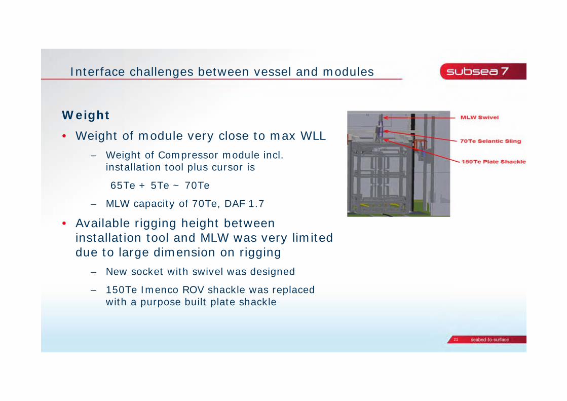
Interface challenges between vessel and modules
Weight • Weight of module very close to max WLL
– Weight of Compressor module incl. installation tool plus cursor is
65Te + 5Te ~ 70Te
– MLW capacity of 70Te, DAF 1.7
• Available rigging height between installation tool and MLW was very limited due to large dimension on rigging
– New socket with swivel was designed
– 150Te Imenco ROV shackle was replaced with a purpose built plate shackle

22
Interface challenges between vessel and modules
• Height of modules– Modules needs to be lifted above
skidding pallet
– Modules needs to be lifted high enough for moon pool hatches to be opened

23
Interface challenges between vessel and modules
• New for supplier how module handling on a vessel is performed – Focus was on subsea interfaces
– Requirement for transport pallets on deck
– Deck logistic
– Sea fastening cases (operation and transit)
– Load picture when cursor frame is initiated
• Design and fabrication of the Module Handling System on Seven Viking was not completed when initiating interface towards Onesubsea -> Lack of available information
• ROV interface

24
Interface challenges between vessel and modules
Guide Funnels and cursor Prongs not strong enough• Old prong design allow approx. 2 degree tilting of module before moment
force in cursor frame and module funnels occur
• New Prong design to avoid moment forces in Cursor Frame
New ball end design allows 6° tilt
New designOld design

25
Operational criteria (sea state)
• The governing criteria is given when the module is hanging in the air
• The criteria was given by the module response relative to the vessel
• The module was allowed to move +/- 60cm transvers and +/-80 cm longitudinal

26
Operational criteria (sea state)
• SIMO analysis showed that large pendulum movement in longitudinal direction would occur in waves with period of about 5 sec. due to resonance motions. Expected sea state around 1.5 m HS
• To increase the weather criteria two measures were put in place– Bumper acting on top cursor
– Vessel response forecast
27
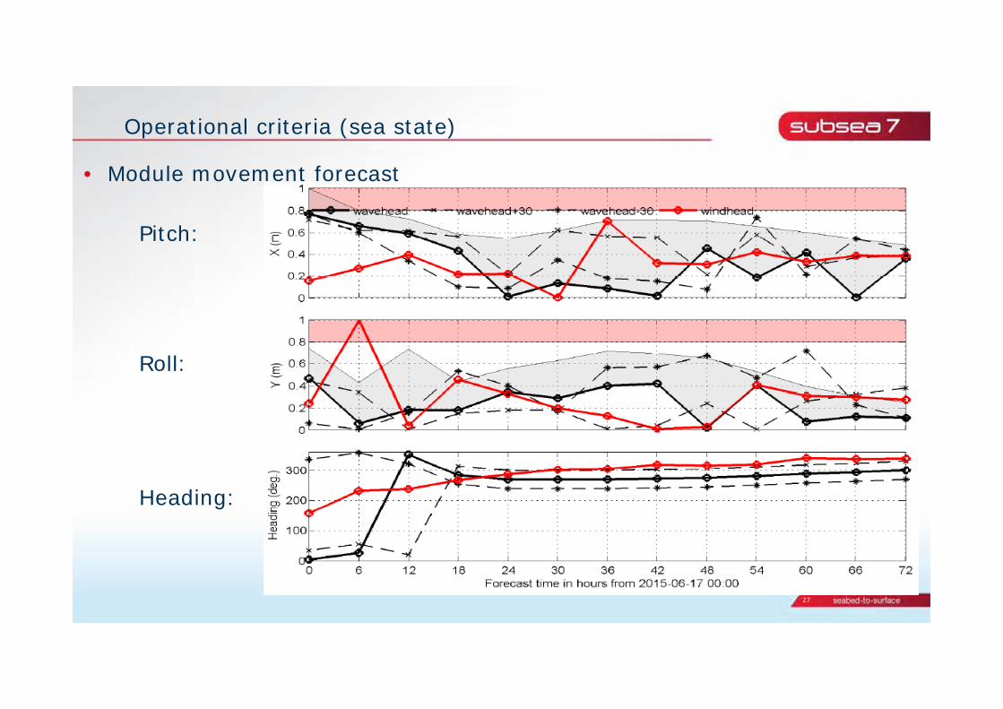
Operational criteria (sea state)
• Module movement forecast
Pitch:
Roll:
Heading:
28
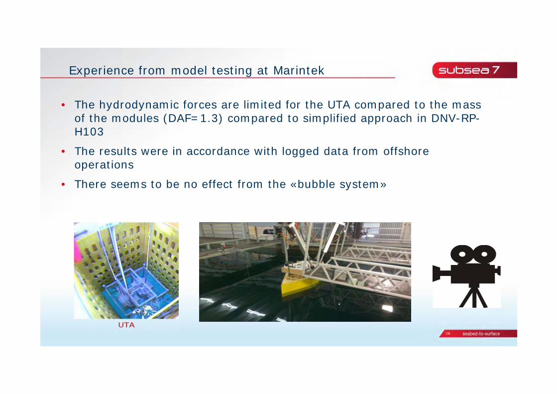
Experience from model testing at Marintek
• The hydrodynamic forces are limited for the UTA compared to the mass of the modules (DAF=1.3) compared to simplified approach in DNV-RP-H103
• The results were in accordance with logged data from offshore operations
• There seems to be no effect from the «bubble system»
29
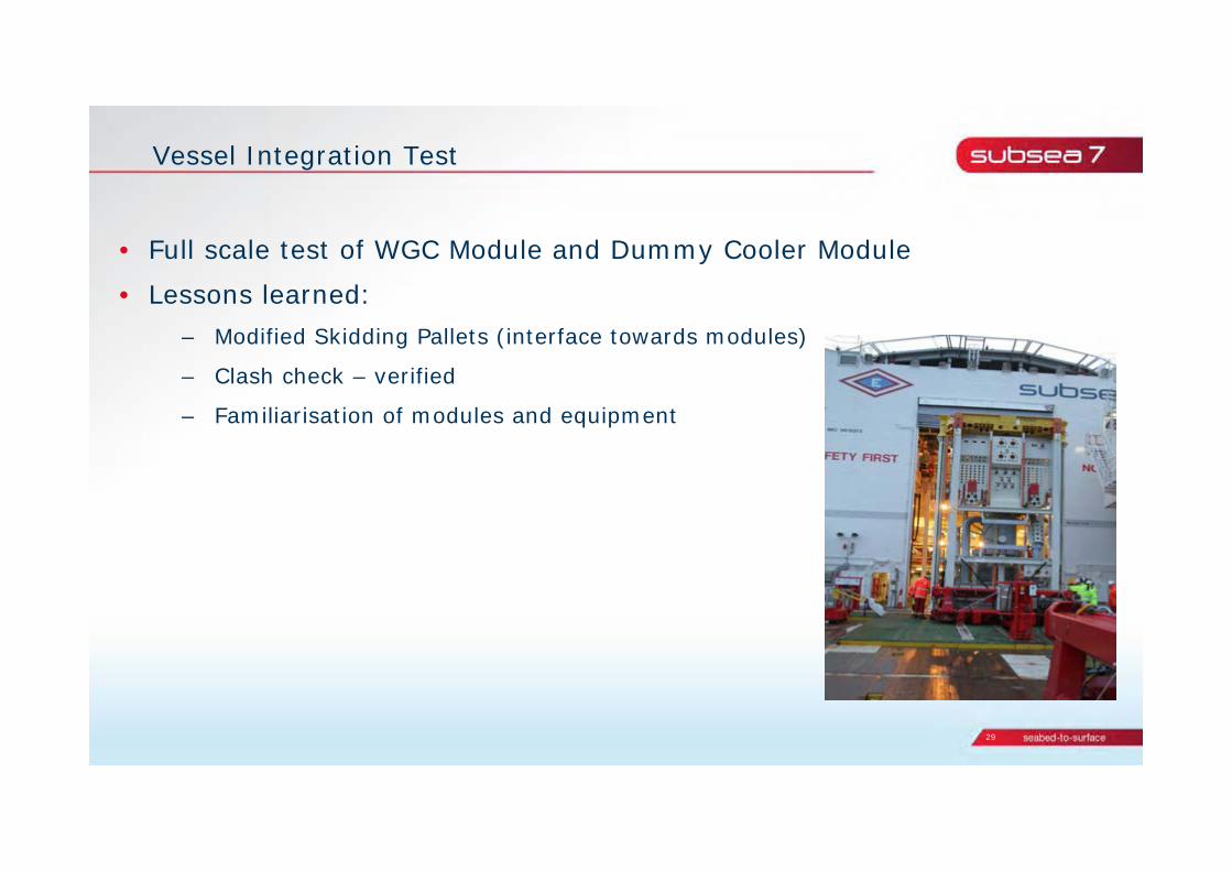
Vessel Integration Test
• Full scale test of WGC Module and Dummy Cooler Module
• Lessons learned:– Modified Skidding Pallets (interface towards modules)
– Clash check – verified
– Familiarisation of modules and equipment

30
Offshore operations
• 2-off Cooler Module and 2-off WGC Module installed successfully

31
1st time installation VS future intervention
• Main difference is the recovery phase where docking of the modulewill be carried out below the splash zone. Requirement for Cursor Camera.
• Procedures and concepts for recovery of modules, UTA and essential parts are established

32 seabed-to-surface32 seabed-to-surface32
Marine Operations

33
• SIMOPS
Busy installation season
The plan....
....and real life.

34
Marine Operations
• Gullfaks Subsea Compression Installation work

35