Embed Size (px)
Citation preview

GUIDELINES FOR ROAD DESIGN, CONSTRUCTION, MAINTENANCE AND
SUPERVISION
Volume I: DESIGNING
Section 2: DESIGNING BRIDGES
DESIGN GUIDELINES (DG 1.2.8) Part 8: TRANSITION FROM THE ROAD TO THE BRIDGE


Guidelines for Road Design, Construction, Maintenance and Supervision Transition
RS-FB&H/3CS – DDC 433/94 Volume 1 - Section 2 - Part 8 Strana 3 od 40
INTRODUCTION Bridges represent a discontinuity in the road body laying-out due to the change of material and the way of transferring the load into the ground. Therefore, excessive differential settlements between the bridge structure and the road body may occur. Bridge abutments are rigid structures, without settlements or with minor ones only. On the contrary, road bodies are less rigid than bridges depending on the type and quality of the soil below road fills. Consequently, road body settlements are considerable and of a long duration. The present Design Guidelines deal with problems occurring during construction of backfill wedges at abutments, of transition slabs, and wing walls, as well as with the settlements around abutments. As bridges represent a discontinuity in the road body alignment, excessive differential settlements may occur between the bridge structure and the adjacent road fill.Designers and experts in soil mechanics shall solve the problem of differential settlements between the bridge and the road body (fill, cut), taking into account the order of magnitude of these settlements. For the transition from the non-rigid road body to the rigid bridge structure, transition slabs are foreseen. In this way, impacts and differences in the deformability, that could affect traffic safety and impose additional dynamical loads to the structure, are prevented. Wing walls are constituent structural elements of bridge abutments. They ensure stability of fills and backfills at both bridge accesses as well as give form to connecting cones of the road body. Wing walls are constructed of reinforced concrete of equal material characteristics as bridge abutments that they are directly connected with. The wing wall length is limited by the structural design and should be economical. Therefore, wing walls of excessive length must be avoided. If longer wing walls are directed by the ground relief expansion joints shall be introduced and the wing wall will proceed to a retaining wall. In these Design Guidelines, basic types of wing walls are indicated with regard to their position and structure. Basic geometric parameters as well as the principles of static analysis and reinforcing of wing walls are presented. For any road bridge a contact between the bridge and the ground shall be brought to effect. Such a contact of the road body with the bridge can be raised or solid.In the present Design Guidelines functional, geometrical and aesthetical problems appearing at the contact of the road with a bridge in a fill, a cut and a mixed profile (cut and fill) are discussed. The purpose of these Design Guidelines is to provide general directives, details and schemes for a correct solution of the transition of the road from the road body to the bridge. A visual and constructive transparent solution and connection shall be attained.

Transition Guidelines for Road Design, Construction, Maintenance and Supervision
Strana 4 od 40 Volume 1 - Section 2 - Part 8 RS-FB&H/3CS – DDC 433/94
C O N T E N T S 1 SUBJECT OF DESIGN GUIDELINES..........................................................................................5 2 REFERENCE REGULATIONS.....................................................................................................5 3 EXPLANATION OF TERMS .........................................................................................................5 4 BACK FILL WEDGES AT ABUTMENT ........................................................................................6
4.1 General................................................................................................................................6 4.2 Determination of differential settlements between the bridge and the road body...............7 4.3 Measures for reduction of differential settlements ..............................................................7 4.4 Execution of fills and backfill wedges..................................................................................7
5 TRANSITION SLABS..................................................................................................................14 5.1 General..............................................................................................................................14 5.2 Criteria for selection of solution of transition from the bridge carriageway to the road
carriageway .......................................................................................................................14 5.3 Solutions and details with transition slab ..........................................................................15 5.4 Solutions and details without transition slab .....................................................................16
6 WING WALLS .............................................................................................................................23 6.1 General..............................................................................................................................23 6.2 Parallel wing walls .............................................................................................................23 6.3 Inclined wing walls.............................................................................................................24 6.4 Rectangular wing walls .....................................................................................................25 6.5 Independent wing wall.......................................................................................................26 6.6 Cantilever wings................................................................................................................26 6.7 Combined independent-cantilever wings ..........................................................................26 6.8 Geometric parameters of wing walls .................................................................................26 6.9 Calculation, design and reinforcing of wing walls .............................................................28
7 SETTLEMENTS AROUND ABUTMENT ....................................................................................29 7.1 Shapes of the contact between the bridge and the road body .........................................29 7.2 Berms ................................................................................................................................32 7.3 Cones ................................................................................................................................33 7.4 Paving the slopes..............................................................................................................34 7.5 Dewatering the contact between the bridge and the road body .......................................35

Guidelines for Road Design, Construction, Maintenance and Supervision Transition
RS-FB&H/3CS – DDC 433/94 Volume 1 - Section 2 - Part 8 Strana 5 od 40
1 SUBJECT OF DESIGN
GUIDELINES The present Design Guidelines deal with problems occurring during construction of backfill wedges at abutments, of transition slabs, and wing walls, as well as with the settlements around abutments. As bridges represent a discontinuity in the road body alignment, excessive differential settlements may occur between the bridge structure and the adjacent road fill. Designers and experts in soil mechanics shall solve the problem of differential settlements between the bridge and the road body (fill, cut), taking into account the order of magnitude of these settlements. The mentioned order of magnitude of the permissible differential settlements should be defined by the terms of reference for the particular road category (chapter 4). For the transition from the non-rigid road body to the rigid bridge structure, transition slabs are foreseen. In this way, impacts and differences in the deformability, that could affect traffic safety and impose additional dynamical loads to the structure, are prevented (chapter 5). The magnitude of the road fill deformation behind the abutment can be reduced and controlled by transition slabs being constituent parts of abutments of rear walls of frame structures. Wing walls at bridge abutments are discussed in the chapter 6, whilst the chapter 7 deals with the settlements around bridge abutments. The present Design Guidelines specify conditions of application of different wing wall types as well as the geometric parameters. Basic principles of static analysis as well as of the reinforcing of wing walls are also indicated. The contact of the road body with the bridge or the transition from the bridge to the road body represents a discontinuity in view of both load bearing capacity and aesthetics. Therefore, both bridge designer and road designer shall cooperate in designing the contact between the road body and the bridge. They shall specify or design the slope angles, berms and widening, as well as define the transition from the bridge superstructure to the road pavement
structure taking into consideration concrete safety barriers, steel safety barriers, kerbs, drainage, shafts, installations, noise barriers, etc. 2 REFERENCE REGULATIONS - Rulebook of technical norms for concrete
and reinforced concrete made of natural and artificial lightweight aggregate filler, Official Gazette of SFR Yugoslavia, No. 15-296/90
- Rulebook of technical norms for foundation of structures, Official Gazette of SFR Yugoslavia, No. 15-295/90,
- Rulebook of technical norms for determination of magnitude of actions on bridges (January 4, 1991)
- Guidelines for road design (Volume 1 – Part 1) in Bosnia and Herzegovina
- Slovenian technical specifications for bridges: TSC 07 108, TSC 07 109, TSC 07 110
- Directive drawings for bridges and other civil engineering structures, issued by the German Federal Ministry for Traffic, Road Construction Department, 1994 and 1995 (Richtzeichnungen für Brücken und andere Ingenieurbauwerke)
- Guidelines for bridges, issued by the German Federal Ministry for Traffic, Road Construction Department, 1995
(Richtlinien für Brücken) 3 EXPLANATION OF TERMS Overlay is an artificial accumulating of material to create, as a rule, an earth body of certain shape. Backfill wedge is a void appearing at the bridge or its abutment respectively, when the bridge construction commences simultaneously with the execution of the road body in the near vicinity of the bridge structure. Settlement is a vertical, downwards orientated movement of the structure due to compression of the foundation ground or fill under static or dynamic loading. Drainage is a constructive device for collecting and leading-away of free water in the ground. Water-impermeable soil is such a soil that is resistant to penetration of water under certain pressure.

Transition Guidelines for Road Design, Construction, Maintenance and Supervision
Strana 6 od 40 Volume 1 - Section 2 - Part 8 RS-FB&H/3CS – DDC 433/94
Water-permeable soil is such a soil that is not resistant to penetration of water under certain pressure. Transition slab is an element placed on the road fill attaching the bridge. It prevents an eventual height difference (step) between the carriageway on the connecting fill and the carriageway on the bridge. Wing wall is a structural element of the abutment at both ends of a bridge. It serves for transition from the road body to the bridge. Wall parameters are certain limitations and provisions serving for economical design of individual wall types. Inclination of wall rear side is an obliqueness specified by the soil mechanics characteristics of the fill or cut of the ground to which a bridge is attached. Cantilever on the wing wall top serves for fastening the edge beam, walkway and railing. Strengthening column is a local widening of the wing wall in the place where the wall proceeds to its cantilever part. The mentioned widening can be equal to the foundation width and it can run along the entire wing wall height or only up to the point where the cantilever part of the wing wall commences. Length of a wing wall is the distance from the place, where the wall is fixed to the abutment, to the wing wall end. Slope is the steep inclined side of the fill or cut. Fill is a raised and stabilized road body. Cut is a spread excavation in the natural ground for the needs of road construction. Mixed profile is a combination of a cut and a fill in a slope. Cone is a shape of the fill termination at the bridge. Shoulder is a widened part of the road body out of the carriageway. Berm is a widened, generally horizontal part of the cut or fill.
Rectangular bridge is such a bridge, which axis intersects the axis of an obstacle at an angle of 90°. Oblique bridge is such a bridge, which axis intersects the axis of an obstacle at an angle ≠ 90°. Slope angle of 1 : n is a ratio of the height to the length. Paved surface is a surface below the bridge, artificially protected from erosion. Channel is a regulated and stabilized zone for draining the precipitation water. Gutter element is a precast element of a channel shape intended for draining the precipitation water. Cascade is a type of a drain channel having the shape of a step; by means of a cascade, the prescribed fall of the channel is made feasible. 4 BACK FILL WEDGES AT
ABUTMENT 4.1 General The term road means a traffic surface whose load bearing structure is formed by a road body generally constructed of natural earth materials in a shape of a fill, a cut or their combination. The road body is founded on a natural ground on which the road laying-out runs. Due to the terrain configuration and different impediments on it such as deep valleys, rivers, existing roads, railway lines etc., the road body cannot be exclusively constructed of earth material along the entire route. Certain road sections must be made in a form of different bridges, viaducts etc. representing a discontinuity in the road body laying-out. Within the framework of its purpose, a road shall ensure a safe and comfortable traffic. This can be achieved by a sufficient bearing capacity and, to a highest possible degree, by unchangeable design geometry in vertical and horizontal sense. Bridges represent a discontinuity in the road body laying-out due to the change of material and the way of transferring the load into the ground. Therefore, excessive differential settlements between the bridge structure and the road body may occur.

Guidelines for Road Design, Construction, Maintenance and Supervision Transition
RS-FB&H/3CS – DDC 433/94 Volume 1 - Section 2 - Part 8 Strana 7 od 40
4.2 Determination of differential
settlements between the bridge and the road body
The duty of road designer, bridge designer, and soil mechanics expert is to solve the problem of differential settlements between the bridge and the road body (fill, cut), taking into consideration the order of magnitude of settlements. The mentioned order of magnitude of the permissible differential settlements should be defined in the design specification for the particular road category. The problem of differential settlements between the bridge and the connecting road body shall be solved in a special design chapter or in the geological-soil mechanical report by adequate calculations of absolute settlements of both the bridge and the road body. On the basis of comparison of those values, the bridge designer, the road designer, and the soil mechanics expert specify eventual modifications in the conceptual design of one and/or another load bearing structure. 4.3 Measures for reduction of differential
settlements The road designer, the bridge designer, and the soil mechanics expert shall determine the construction technology for the bridge abutment and the execution method for the connecting earth fill, including a definition of time sequence of the individual construction stages. The mentioned experts shall also harmonize the quality of backfilling material in order to clearly specify the earth pressures acting onto the abutment, and to assess correctly the effects of fill compaction on the abutment stability. Both designers and the soil mechanics expert shall specify the geometry of the connecting fill (slopes, berms, widening at the bridge etc.) including the transition from the bridge superstructure to the road carriageway structure (concrete safety barrier, steel barriers, kerbs, drainage, shafts, transition slabs etc.). The drawings in both the road design and bridge design shall be harmonized. The road designer can influence the magnitude of the fill absolute settlements by the following: - Preliminary preparation of the compressible
layer of the future fill foundation soil by preliminary loading, horizontal and vertical drainage, replacement of soil-in-situ with an improved material, load transfer into the depth by means of sand piles, etc.
- Type of selected material for construction of the connecting road fill.
- Maximum fill height on the known thickness
of compressible layer of foundation soil, which the bridge length depends on. Excessively deformable connections to the bridge shall be avoided.
The bridge designer can influence the magnitude of the bridge abutment absolute settlements particularly by selecting the foundation method. amentally, a bridge can be founded on flexible or rigid ground. Generally, both shallow and deep foundation is possible. Since for modern, statically undetermined bridges, the abutment settlements shall be as small as possible, special attention has to be paid to a correct design and execution of the road connecting fill, and consequently to a proper location of abutments, which the bridge length depends on. In case that the road carriageway is made of gravel, the problem of differential settlements is practically unimportant, since the arisen height difference can be accommodated by periodical additional macadamising of the carriageway. For modern motorways, the matter is less simple because not only levelling asphalt must be applied but also all the elements of the road carriageway structure (such as barriers, kerbs and shafts) have to be corrected in height. 4.4 Execution of fills and backfill wedges In construction practice it generally happens that the bridge construction commences simultaneously with the road body construction in the immediate vicinity of the bridge. As a consequence, voids called wedges occur at bridges or their abutments. The problem of differential settlements between the bridge and the connecting road fill is even increased by those wedges. Due to the final stages of bridge construction (e.g. pre-stressing of superstructure), the connecting road fill can generally not be executed immediately after completion of abutments. However, the road contractor tends towards a prompt balance of earth masses along the road route, therefore he forces the fill construction in the bridge vicinity as well. Practically in all cases the joint between the bridge and the fill or soil-in-situ shall be carried out by compacted earth material, i.e. a fill and backfill respectively. Is the bridge higher than the soil-in-situ, problems with connecting road fill may occur. However, if the bridge is below the soil-in-situ level, backfilling can become problematic.

Transition Guidelines for Road Design, Construction, Maintenance and Supervision
Strana 8 od 40 Volume 1 - Section 2 - Part 8 RS-FB&H/3CS – DDC 433/94
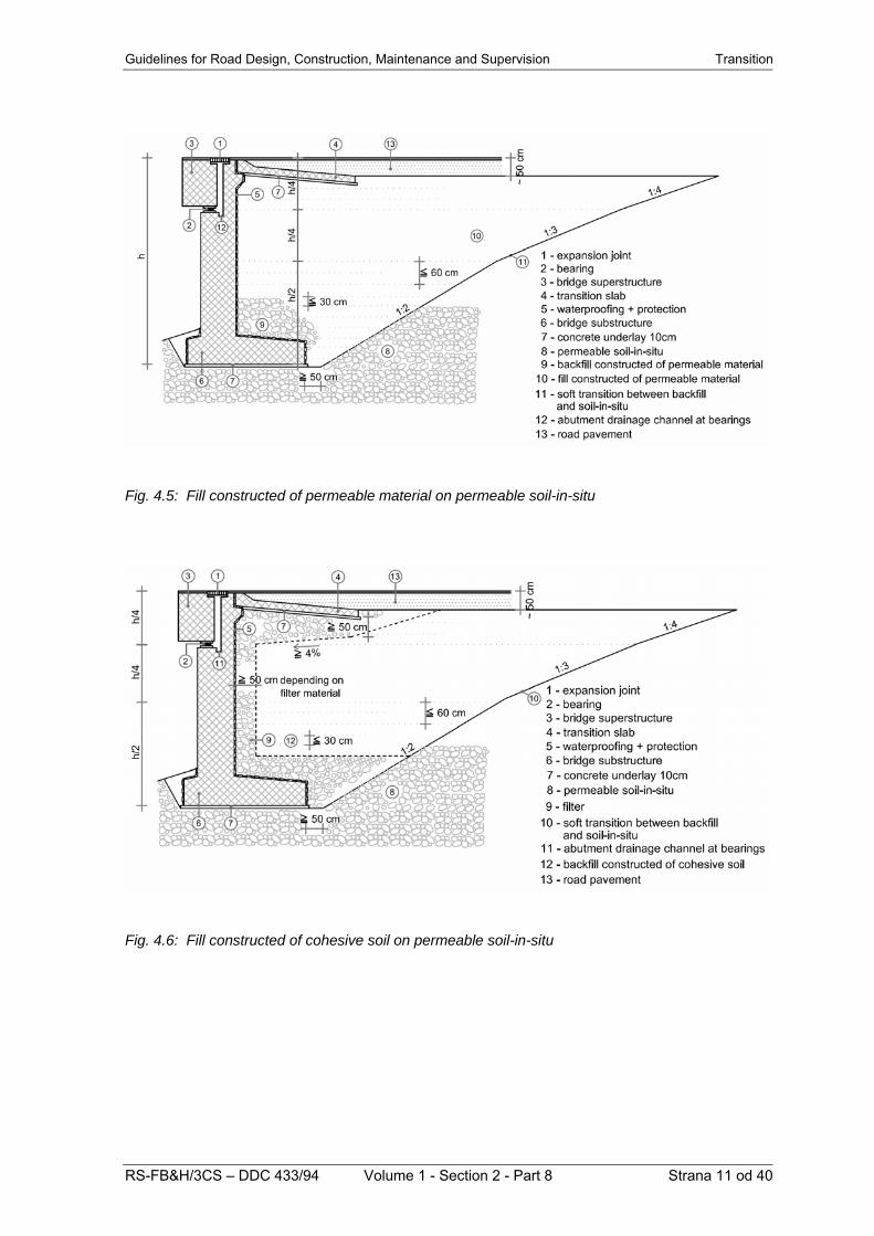
Solutions of fill execution differ from those for backfilling. Accumulation of water behind abutments and creation of hydrostatic pressure can be prevented by carrying out a filter layer of suitable permeable stone material, by applying filter bricks to the abutment wall or by building-in of another permeable material. If a filter is foreseen, backfill or fill can be in principle made of cohesive or non-cohesive soils, provided that an adequate compaction and permissible settlements can be achieved. Attention should be paid to a satisfactory outflow of water accumulating in the layer behind abutment. In case that the foundation bottom is located in a permeable ground, it is sufficient to connect directly the filter layer with permeable soil-in-situ, while the fill or the backfill behind abutment are made of available backfilling material. When the foundation bottom is located in an impermeable ground, the construction pit around the foundation shall be backfilled with compact clay up to the contact with soil-in-situ, while the impermeable ground surface shall be inclined towards the drainage to be placed at the soil-in-situ level. Up to a half, the drainage pipe is built-in into concrete base being in contact with compact clay. Onto the drainage performed in such a way, a filter layer is executed at the abutment wall simultaneously with fill or backfill. The drainage shall be attached to a suitable recipient (surface ditch or sewer). Fill or backfill height, material quality and compaction required are essential criteria to decide whether a transition slab should be constructed or not. The most suitable material for the easiest building-in and compaction is permeable stone material. For gravel wedges, only outflow of water from the contact between the gravel wedge and the soil-in-situ shall be ensured, if the latter consists of impermeable material. In case that a quality earth material is available on construction site, e.g. quality clays and marls, while gravel locations are far away, earth material won by excavation works on the road route can be used for backfill wedge construction, since such a solution is the most economical one. However, filter at the abutment cannot be avoided in this case.
In principle, the fill construction technology (also in close vicinity of the bridge), the fill compaction rate and the method of preparation of foundation (in-situ) soil are specified in relevant codes. More detailed, those requirements are given in tender documents. Cases representing special difficulties shall be worked out very exactly in the design. This particularly applies to construction of wedges at bridges that are not specially comprehended in codes. Figures below show fundamental principles to be taken into consideration for construction of wedges. In figures 4.1, 4.2, 4.3 and 4.4, four characteristic examples of backfill wedge construction are shown in case that the abutment is located in a cut. In figures 4.5, 4.6, 4.7 and 4.8, four characteristic examples of construction of the road fill portion next to abutments. In figures 4.9 as well as in table 4.1, details and requirements for compaction in case of fill construction in zone A, i.e. 200 cm below the vertical alignment, and in zone B, i.e. in the remaining lower part of the fill. In order to construct backfill wedges or fills behind abutments with smallest possible settlements, permeable stone material shall be used, since it can be compacted quite easily and no special filter layers are necessary. The inner part of abutment structure shall be as simple as possible, with even surfaces, to enable an easy building-in and compaction of backfill wedges as well as accessibility for compacting means. From the above mentioned facts it is evident that a permeable stone material is the most suitable material for construction of fills or backfills in the wedge area, since no filters are required in such cases.

Guidelines for Road Design, Construction, Maintenance and Supervision Transition
Fig. 4.1: Cut in permeable ground – backfill with permeable material
Fig. 4.2: Cut in impermeable ground – backfill with permeable material
RS-FB&H/3CS – DDC 433/94 Volume 1 - Section 2 - Part 8 Strana 9 od 40

Transition Guidelines for Road Design, Construction, Maintenance and Supervision
Fig. 4.3: Cut in impermeable ground – backfill with cohesive soil
Fig. 4.4: Cut in rock – backfill with permeable material
Strana 10 od 40 Volume 1 - Section 2 - Part 8 RS-FB&H/3CS – DDC 433/94
Guidelines for Road Design, Construction, Maintenance and Supervision Transition
Fig. 4.5: Fill constructed of permeable material on permeable soil-in-situ
Fig. 4.6: Fill constructed of cohesive soil on permeable soil-in-situ
RS-FB&H/3CS – DDC 433/94 Volume 1 - Section 2 - Part 8 Strana 11 od 40

Transition Guidelines for Road Design, Construction, Maintenance and Supervision
Fig. 4.7: Fill constructed of permeable material on impermeable soil-in-situ
Fig. 4.8: Fill constructed of cohesive soil on impermeable soil-in-situ
Strana 12 od 40 Volume 1 - Section 2 - Part 8 RS-FB&H/3CS – DDC 433/94

Guidelines for Road Design, Construction, Maintenance and Supervision Transition
Fig. 4.9: Details and compaction requirements Table 4.1: Compaction requirements for construction of fills (zone A), backfills (zone B), and substructure formation level
zone A zone B substructure
formation level C.R. Ev2 modul
of deformation (acc. to
DIN)
C.R. Ev2 modul of
deformation (acc. to
DIN)
C.R. Ev2 modul of deformation
(acc. to DIN)
non-cohezive
composition
98 % 60 non-cohezive composition
95 % 45 non-cohezive composition
100 %
80
cohesive soil
95 % 45 cohesive soil 92 % 20 cohesive soil 98 % 30
soil-in-situ in zone A → same criteria as for the fill in zone A soil-in-situ in zone B → same criteria as for the fill in zone B C.R. (Proctor compaction rate) Ev2 = modulus of deformation below transition slab → modulus Ev2 same as prescribed for formation level
RS-FB&H/3CS – DDC 433/94 Volume 1 - Section 2 - Part 8 Strana 13 od 40

Transition Guidelines for Road Design, Construction, Maintenance and Supervision
Strana 14 od 40 Volume 1 - Section 2 - Part 8 RS-FB&H/3CS – DDC 433/94
5 TRANSITION SLABS 5.1 General
Bridge structures at abutments are non-deformable, without settlements or with minor ones. Road bodies are more deformable than bridges, depending on the type and quality of ground below the fill, on fill height, material type and conditions of fill construction. Settlements of the road body (fill) are greater and of long duration. For the transition from deformable road body to non-deformable bridge structure it is essential to specify necessary measures to avoid negative effects of deformability difference on traffic safety and to prevent additional dynamical loading of the bridge. Settlement of the fill behind abutment creates deformations that cause impact of vehicles upon arrival onto the bridge and upon leaving it, therefore reducing the traffic safety. The slope of deformed fills shall not be greater than 1:200 (0.5%) and 1:300 (0.35%) for motorways respectively. The magnitude of fill deformation behind abutments can be reduced and controlled by introducing transition slabs as constituent parts of abutment or frame structure end wall. For bridges on roads of lower categories and for short bridges on motorways and main roads, solutions without transition slabs are possible as well, provided that requirements specified in 5.2 are fulfilled.
5.2 Criteria for selection of solution of transition from the bridge carriageway to the road carriageway
The following criteria are essential to select a solution of transition from the bridge carriageway to the road carriageway:
- Road category; - Height, material and construction quality
of the fill behind abutment, as well as type and quality of the ground below the fill;
- Height position of the superstructure upper surface with regard to the road vertical alignment.
Road categories are defined by character, volume, speed and safety of the traffic. Three categories can be distinguished: motorways and main roads, regional and local roads, and non-categorized roads (field and forest roads, village roads). Construction methods and materials of fills and backfill wedges behind abutments are described in detail in chapter 4. Provided that a fill is executed in accordance with the criteria and requirements given in chapter 4, only fill height and ground quality under the fill are essential to decide whether a transition slab is required or not. In view of height, three types of fills are distinguished: low fill of up to 6 m height, medium-high fills of 6-10 m height, and high fills of over 10 m height. In table 2 and figure 10, criteria are given to decide whether the transition from the bridge carriageway to the road carriageway should be carried through by a transition slab or without it.
Table 5.1 Criteria for decision whether the transition from the bridge carriageway to the road carriageway should be carried through by transition slab or without it
FILL HEIGHT H (m)
POSITION OF BRIDGE UPPER SURFACE WITH REGARD TO VERTICAL ALIGNMENT h (m)
ROAD CATEGORY
≤ 6 6-10 > 10 0 0.4 – 1.0 > 1.0 MOTORWAYS AND MAIN ROADS YES YES YES YES* YES NO REGIONAL AND LOCAL ROADS NO YES YES NO* NO NO NON-CATEGORIZED ROADS NO NO YES NO* NO NO
YES is a solution with transition slab NO is a solution without transition slab YES* for motorways and main roads it is not recommended to design bridges of length L < 10 m with their upper surface on the motorway or main road vertical alignment NO* a transition slab is not required when measures according to chapter 5.4 are taken and the expected settlement difference amounts to < 15 mm

Guidelines for Road Design, Construction, Maintenance and Supervision Transition
Fig. 5.1: Supplementary explanation of table 5.1 5.3 Solutions and details with transition
slab In point 5.3, elements for the solution with transition slab are given. Fundamental differences in the transition slab design result from the type of road carriageway structure. Roads with asphalt and roads with concrete pavement are known. In Bosnia and Herzegovina, all carriageways of motorways and other roads are made of asphalt; consequently, details and solutions are appropriately adapted to such carriageways. Solutions and details referring to concrete carriageways will be worked out in detail when concrete pavements will be designed for the Slovenian motorways. In figure 5.2, sketches and elements are shown defining geometry and length of transition slabs depending on the angle of obliqueness and on the height of the road fill at abutment. In figure 5.3, reinforcement scheme (combination 3.70 m, 6.20 m, 8.70 m) for 25 cm thick transition slabs is shown. Since profiles and spacing of rebars are given, design static calculation is not required, except in some specific conditions. Concrete grade C25/30 and reinforcement S 400 (Φ 16/20 for anchors) are specified. Transition slabs are concreted on compacted gravel base onto which a layer of lean concrete underlay of 10 cm thickness has been cast previously. The latter follows the transition slab inclination of 10% with regard to the road vertical alignment. The protective concrete cover amounts to 5 cm. Transition slabs lean lineally on the bridge bearing structure. The detail of leaning depends on abutment type: the latter can be
rigidly connected with the bridge superstructure (frame structures) or it is fixed and connected with the superstructure by means of bearings and expansion joint. In figure 5.4, a general solution, whilst in figure 5.5, a detail of supporting of transition slab in case of reinforced concrete frame structures is shown, with a distance from the centre of movement smaller than 30 m when fill settlements not greater than 15 mm are expected. In figure 5.6, a general solution, whilst in figure 5.7, a detail of supporting of transition slab in case of reinforced concrete frame structures is shown, with a distance from the centre of movement between 30 m and 50 m. The transition slab rests on the load bearing structure via neoprene bearing without anchor. As a consequence, movements of the frame structure are not transferred to the transition slab. An asphalt expansion joint is foreseen above the joint between the frame structure and the transition slab.
In figure 5.8, a general solution, whilst in figure 5.9, a detail of supporting of transition slab in case of reinforced concrete beam superstructures of distances up to 100 m between two consecutive expansion joints when fill settlements not greater than 15 mm are expected. In figure 5.10, a general solution, whilst in figure 5.11, a detail of supporting of transition slab in case of reinforced concrete beam superstructures, with a distance from the centre of movement greater than 100 m, when fill settlements not greater than 15 mm are expected. The sketches also include a detail of the chamber serving for inspection, maintenance and replacement of expansion joint.
RS-FB&H/3CS – DDC 433/94 Volume 1 - Section 2 - Part 8 Strana 15 od 40

Transition Guidelines for Road Design, Construction, Maintenance and Supervision 5.4 Solutions and details without
transition slab In table 5.1, conditions and criteria for solutions without transition slabs are indicated. In figure 5.12, a possibility of transition without transition slab is shown for the case where the upper bridge or culvert surface of an opening of less than 10 m (L<10 m) is situated in the vertical alignment of a regional, a local or a non-categorized road. An improved (stabilized) bearing layer shall be foreseen at a length of 2.0 m + 2.0 m.
In figure 5.13, a possibility of transition without transition slab is shown for the case where the upper bridge or culvert surface of an opening of less than 10 m (L<10 m) is lowered by 40 cm minimum with regard to the vertical alignment of a motorway or other roads. (For motorways, the expected differential settlement between the bridge and the road fill amounts to < 15 mm). In figure 5.14, a possibility of transition without transition slab is shown for the case where a fill higher than 1.0 m is carried through above a bridge or a culvert of an opening less than 10 m (L<10 m).
Fig. 5.2: Sketches and elements for determination of transition slab length and geometry
Strana 16 od 40 Volume 1 - Section 2 - Part 8 RS-FB&H/3CS – DDC 433/94

Guidelines for Road Design, Construction, Maintenance and Supervision Transition
Fig. 5.3: Scheme of transition slab reinforcement
RS-FB&H/3CS – DDC 433/94 Volume 1 - Section 2 - Part 8 Strana 17 od 40

Transition Guidelines for Road Design, Construction, Maintenance and Supervision
Fig. 5.4: Transition slabs for reinforced concrete frame bridge structures with a distance of < 30 m from the centre of movement
Fig. 5.5: Detail of supporting and top of transition slab for reinforced concrete frame bridge structures with a distance of < 30 m from the centre of movement
Strana 18 od 40 Volume 1 - Section 2 - Part 8 RS-FB&H/3CS – DDC 433/94

Guidelines for Road Design, Construction, Maintenance and Supervision Transition
Fig. 5.6: Transition slabs for reinforced concrete frame structures with a distance of 30 m - 50 m from the centre of movement
Fig. 5.7: Detail of supporting and top of transition slab for reinforced concrete frame bridge structures with a distance of 30 m - 50 m from the centre of movement
RS-FB&H/3CS – DDC 433/94 Volume 1 - Section 2 - Part 8 Strana 19 od 40

Transition Guidelines for Road Design, Construction, Maintenance and Supervision
Fig. 5.8: Transition slabs for reinforced concrete beam bridge superstructures of distances of ≤ 100 m between two consecutive expansion joints
Fig. 5.9: Detail of supporting and top of transition slab for reinforced concrete beam bridge superstructures with a distance of ≤ 100 m from the centre of movement
Strana 20 od 40 Volume 1 - Section 2 - Part 8 RS-FB&H/3CS – DDC 433/94

Guidelines for Road Design, Construction, Maintenance and Supervision Transition
Fig. 5.10: Transition slabs for reinforced concrete beam bridge superstructures of distances of > 100 m between two consecutive expansion joints
Fig. 5.11: Detail of supporting and top of transition slab for reinforced concrete beam bridge superstructures with a distance of > 100 m from the centre of movement
RS-FB&H/3CS – DDC 433/94 Volume 1 - Section 2 - Part 8 Strana 21 od 40

Transition Guidelines for Road Design, Construction, Maintenance and Supervision
Fig. 5.12: Solution without transition slab for culverts and bridges of opening up to 10 m on regional, local and non-categorized roads
Fig. 5.13: Solution without transition slab for culverts and bridges of openings up to 10 m on roads of all categories
Strana 22 od 40 Volume 1 - Section 2 - Part 8 RS-FB&H/3CS – DDC 433/94

Guidelines for Road Design, Construction, Maintenance and Supervision Transition
Fig. 5.14: Solution without transition slab where a fill higher than 1.0 m is placed above culverts or bridges of openings up to 10 m 6 WING WALLS 6.1 General In the longitudinal direction, a wing wall represents the beginning or the end of a bridge. It is in close relation to the relief of the ground where the structure is located. Classification of wing walls, their properties and characteristics, as well as geometric parameters and design recommendations are given below. Moreover, other important design parameters such as conditions imposed by water economy experts, geometry, sight on the road below the structure, geological conditions etc. are mentioned as well. Wing walls can be classified with regard to their position and to their structure. Classification of wings with regard to their position: - Abutments with parallel wings - Abutments with inclined wings - Abutments with rectangular wings. Classification of wings with regard to their structure: - Independent wing walls - Cantilever wings - Combined independent-cantilever wing
walls.
6.2 Parallel wing walls Generally it can be said that parallel wing walls give the most appropriate appearance of a structure (figure 6.1). Therefore, abutments with parallel wings are recommended for locations where an optimum structural shape should be achieved. However, good results can be obtained with other wing shapes as well, taking into account the location of the structure. Parallel wings are capable to retain the backfill earth wedge located between both wings. As a consequence, settlement of the fill behind the abutment is reduced. The backfill wedge behind the abutment shall be compacted in 30 cm thick layers up to the specified density. In general, this can be achieved by means of suitable compaction machines. However, during compacting process, an additional lateral pressure acts on the wings, which must not be neglected when specifying the wing thickness and designing the wings.
RS-FB&H/3CS – DDC 433/94 Volume 1 - Section 2 - Part 8 Strana 23 od 40

Transition Guidelines for Road Design, Construction, Maintenance and Supervision
Fig. 6.1: Parallel wing wall In case of parallel wings the rear water does not accumulate in the backfill wedge area, since it can be led away behind the abutment out of the structure area. If the wings are parallel, the superstructure bearing can be visible or hidden behind the wall, which is an actual extension of the wing wall (figure 6.2) enabling better anchoring of the wing wall reinforcement.
Fig. 6.2: Visible and hidden bearing of the bridge superstructure
6.3 Inclined wing walls Inclined wings offer several possibilities of designing the transition from the bridge to the surrounding area, since such wings can be executed at any acute angle with regard to the bridge axis. The angle α varies between 30° and 90°. Inclined wings can also enable a better entry to the profile below the bridge than the parallel ones (e.g. for a water stream). However, it should be noted that both, the abutment and the inclined wing, must create a visual integrity. In figures 6.3 and 6.4, examples of inclined wings are shown. Those wings are extremely accentuated while the wing itself is connected with the abutment in a slope. However, the wing can be carried out completely vertically. Generally, the height of inclined wings decreases with going away from the structural axis and follows the embankment slope. There is also a possibility to design an inclined wing in a constant height along the entire length, or to lower it only partly. Those height differences can be carried out stepwise as well. Using these variable elements, a more suitable appearance of the abutment can be attained.
Fig. 6.3: Inclined wing wall in a slope
Fig. 6.4: Inclined wing wall with a vertical wing
Strana 24 od 40 Volume 1 - Section 2 - Part 8 RS-FB&H/3CS – DDC 433/94

Guidelines for Road Design, Construction, Maintenance and Supervision Transition It is also not indispensable that the visible side of the abutment is vertical, but it can also be inclined. However, it is recommended to apply such solutions after a due consideration, and to pay full attention the design of the visible abutment wall (e.g. stone facing, relief concrete, etc.). There is also another possibility, where short parallel wings continue to inclined ones (figure 6.5). However, such solution, in comparison with the others, does not fulfil all aesthetic criteria, since certain shape deficiencies can be noticed.
Fig. 6.5: Inclined wing attached to a short parallel wing In figure 6, a detail of attachment of an inclined wing wall to the abutment is shown. Yet, the connecting angle is limited to α ≥ 30°.
Fig. 6.6: Detail of attachment of an inclined wing to the abutment Also in case of inclined wing walls, the bridge superstructure bearing can be either visible or hidden behind the wall. In general, inclined wing walls are used for bridges where the angle between the bridge axis and the bridged impediment is acute (α ≤ 75°), thus the bridge obliqueness must be adjusted to the ground (figure 6.7).
Fig. 6.7: Plan of a bridge with inclined wings There are several other possibilities for the design of inclined wings, such as curvature of wings in plan. In this way, accommodation to the backfill wedge is better. Moreover, the backfill wedge angle can be varied as well. The end of an inclined wing wall should run pointedly, but such a solution is not appropriate. Therefore, it shall be interrupted a bit before, and a backfill wedge is arranged around the inclined wing wall end. 6.4 Rectangular wing walls As a matter of fact, rectangular wings are a special case of inclined wing walls. Therefore, for the rectangular wings the same presumptions are valid as for the inclined ones (figure 6.8). In a great majority, the use of such wing walls is conditioned by the ground, on which the structure is located, as for example, where retaining walls already exist (water stream bed, road in a cut).
Fig. 6.8: Rectangular wing wall
RS-FB&H/3CS – DDC 433/94 Volume 1 - Section 2 - Part 8 Strana 25 od 40

Transition Guidelines for Road Design, Construction, Maintenance and Supervision
Strana 26 od 40 Volume 1 - Section 2 - Part 8 RS-FB&H/3CS – DDC 433/94
For independent structures located in an open land, such wings are not appropriate, since they would make impossible a look at the bridge, and the width of the opening below the bridge would be optically increased. The wing ends can be designed in the same way as already mentioned for the inclined wings. However, a backfill wedge at wing ends is not desired. 6.5 Independent wing wall The simplest solution is a combination of a massive abutment and independent wing walls placed on both sides. In this way, each structural element (abutment, wing) can be analysed extra. The dimensioning shall be performed in such a manner that the stability conditions are ensured and that the permissible foundation soil stresses are not exceeded. Such walls can be constructed of stone, concrete or reinforced concrete. Independent wing walls are used when retaining walls protecting the road body are designed at the bridge. Therefore, their shapes and design solutions are the same as for the retaining walls, thus ensuring a uniform appearance of both, the bridge as well as the carriageway next to the bridge. In case of independent wing wall, special attention shall be paid to a correct design of the expansion joint. If a gravity wing wall is relatively high and founded in poor ground, it tends to lean outwards. The abutment wall, which is orientated in the rectangular direction, cannot follow those movements. As a consequence, a dislocation occurs, the walkway is damaged (if its expansion joint is not in the same place), and some soaking appears as well if the joint is not sealed with a strip having a sufficient moving capacity. 6.6 Cantilever wings The use of cantilever wings is to a great extent conditioned by the relief of the ground where the bridge is located. In case that the load bearing ground is relatively low under the upper level of the existing ground, also the abutment will be of such a height that cantilever wings will be realizable at assumed inclination of the backfill cone. This means that under the wing itself no reinforced concrete foundations will be required. The application of cantilever wings is directed also by the wing length itself. Wings that are longer than 6.0 m should not be attached to abutments as cantilever ones.
6.7 Combined independent-cantilever
wings Those wings are carried out where wings longer than 6.0 m are required by the ground. First, an independent wing wall is constructed, from which a cantilever wing continues. 6.8 Geometric parameters of wing walls Dimensional parameters of wing walls are the following: - Length, thickness and lower end - Relation between the wing and the ground
inclination - Cantilever overhang at the ends of the wing
wall. A wing wall should end at least 1.0 m behind the point where the plane of the final ground is attached to the carriageway plane or to the carriageway vertical alignment. The minimum thickness of wing walls shall amount to 30 cm for cantilever wings of 4.0 m length, and 40 cm for longer cantilever wings respectively. The connecting wall between the cantilever wing and the abutment must be at least 60 cm thick. Such a dimension enables an adequate placing of reinforcement in the area of transition from the cantilever wing to the abutment. It also ensures attaining of required dimensions of the protective concrete cover above the reinforcement for elements in contact with soil (5.0 cm). The wing shall not be longer than 10.0 m. The length of the cantilever part of the wing wall shall be between 2.0 m and 6.0 m (figure 6.9). In case where the cantilever wing continues from the intermediate wall, its length should not exceed 5.0 m in order to keep loading within such an order of magnitude that no difficulties occur when arranging the reinforcement in the cross section. If a longer wing wall is directed by the ground relief an expansion joint shall be carried out, and the continuation of the wing wall must be treated apart of the structure (retaining wall). It is also possible to modify the cone inclination by introducing an adequate revetment, or to construct a retaining wall of 2.0 m visible height at the bottom of the cone.

Guidelines for Road Design, Construction, Maintenance and Supervision Transition The minimum height of the wing wall end amounts to 1.0 m. In case that a horizontal wing end is foreseen (its length depends on the inclination of the definitive ground), the minimum height of the wing wall end is 1.50m. Foundation of the wall part of the wing wall is executed together with the front wall of the abutment on the basis of soil mechanics data. Generally, a strip foundation is foreseen. Its width shall be such that the allowable compressive stresses of the foundation ground are ensured.
Fig. 6.9: Geometric parameters of wing walls The inclination of the rear side of the wing wall is equal to the final inclination of the ground (cone, fill, cut) and it is at least 1.0 m below the level of the definitive ground. The inclination depends on the characteristics of the fill or cut and amounts to: i = 1 : 2 fill of cohesive soils i = 1 : 1.5 fill of gravel material i = 1 : 1.25 fill of stone material i = 1 : 1 revetment of stones or
concrete slabs
The width of the walkway on the bridge is greater than the wing wall thickness. Therefore, a cantilever overhang shall be executed on the wing top. To that cantilever overhang, edge beam and railing are fastened. The maximum width if such cantilever overhang is 1.50 m while its thickness amounts to at least 22.0 cm. Figure 6.10 shows different solutions of the cantilever end of a wing wall. It should emphasized that in case of 6.10c, an obliqueness of 60° shall be carried out at the inner side of the wing wall, which enables a quality fill construction. The execution of the cantilever overhang as shown in figure 6.10d, is independent on the fill construction. a)
b)
c)
d)
Fig. 6.10: Ends on the wing wall
RS-FB&H/3CS – DDC 433/94 Volume 1 - Section 2 - Part 8 Strana 27 od 40

Transition Guidelines for Road Design, Construction, Maintenance and Supervision If the cantilever overhang width exceeds 1.50 m, the walkway is interrupted along the wing wall edge, and the joint is filled up with a sealing compound. Below the detached part of the walkway, a quality compaction of the backfill soil shall be carried out. In case that the cantilever wing wall construction is permitted by the ground characteristics, it is reasonable (in order to take vertical loading) to extend the wing in the superstructure area over the abutment. In this way, a better connection between the wing wall and the abutment is ensured (figure 6.11).
Fig. 6.11: Cantilever wing wall with lateral wall at the bridge bearing In case that certain difficulties, related to horizontal deformations occur when carrying out the design dimensioning (effect of the earth pressure and traffic load portion), a strengthening column can be constructed at the end of the wall part of the wing wall. The width of the a.m. strengthening column is equal to the foundation width, while its thickness is equal to the wing wall thickness (figure 6.12). The column can run along the entire wing wall height, or only up to the point where the cantilever part of the wing wall commences.
Fig. 6.12: Strengthening of the wing wall 6.9 Calculation, design and reinforcing of
wing walls In the calculation of internal forces and moments occurring due to action of external loading and dead weight on the wing wall, it can be assumed that the wing wall is a 2D-element fixed to the abutment wall at one edge and to the wing wall foundation at the other edge. The wing wall foundation is connected with the abutment foundation. In case of cantilever wing, only one edge of the wing wall is rigidly supported. All other edges are free and exposed to load action. If the deformations on the top of the wing or the fixed-end moments (restraint moments) are excessive, strengthening of the wing wall can be foreseen in a form of a reinforced concrete column, which partly strengthens the third edge of the wing wall (figure 6.12). In this way, the deformation on the top of the wing wall is reduced, and at the same time the fixed-end moment (restraint moment) at the joint wing-abutment or wing-foundation is diminished as well.
Strana 28 od 40 Volume 1 - Section 2 - Part 8 RS-FB&H/3CS – DDC 433/94

Guidelines for Road Design, Construction, Maintenance and Supervision Transition As a load, the earth pressure force acts on the wing wall. This force is caused by compacted backfill material between both wing walls. The force magnitude increases linearly with the depth (height) of the wing wall. Moreover, the uniformly distributed traffic load acts on the wing wall as well. It acts along the entire wing wall height with a constant value. The design calculation is generally performed by means of computer software for analysing 2D-structures. Those programs usually work on the basis of finite element method (FEM). Figure 6.13 shows the fundamental principle of wing wall reinforcing. Both, external and internal side of he wall is reinforced. The basic spacing between reinforcing bars amounts to e=20 cm, while in the extreme loading area it is only e=10 cm. The overlapping length of individual bars shall satisfy criteria specified in relevant regulations. If the reinforcement is too dense at the transition from the wing wall to the abutment and, as a consequence, some difficulties occur when casting the concrete, a local widening (“voute”) can be carried out. The length and width of that widening shall not exceed the double thickness of the wing wall. The reinforcement for taking the vertical loading is led along the entire wing wall. By means of an appropriate anchor length, the reinforcement is tied up with the abutment wall. The reinforcing bars shall be without any overlapping.
Fig. 6.13: Schematic presentation of the wing wall reinforcement
7 SETTLEMENTS AROUND
ABUTMENT 7.1 Shapes of the contact between the
bridge and the road body The following three basic shapes of the contact between the bridge and the road body can be encountered in practice, where the angle of the bridge to the obstacle amounts to 90°: - contact between the road body and a
bridge in a fill (Figure 7.1); - contact between the road body and a
bridge in a cut (Figure 7.2); - contact between the road body and a
bridge in a mixed profile, i.e. cut and fill (Figure 7.3);
Fig. 7.1: Contact between the road body and a bridge in a fill
Fig. 7.2: Contact between the road body and a bridge in a cut
RS-FB&H/3CS – DDC 433/94 Volume 1 - Section 2 - Part 8 Strana 29 od 40

Transition Guidelines for Road Design, Construction, Maintenance and Supervision
Fig. 7.3: Contact between the road body and a bridge in a mixed profile
Fig. 7.6: Oblique contact between the road body and a bridge in a mixed profile
Further possible shapes of the contact between the road body and the bridge occur where the angle of the bridge to the obstacle amounts to ≠ 90° (Figures. 7.4 – 7.6).
The contact between the road body and the bridge can be shaped in the following two ways (Figure 7.7): a) the cone of the contact between the road body and the bridge begins next to the abutment wall;
b) the cone of the contact between the road body and the bridge is moved below the bridge. In case of a), the bridge is “narrowed”, confined, it seems massive, the sight distance below the bridge is quite poor, the bridge span is shorter, whereas the abutment wings or wing walls are longer; large concrete surfaces are exposed. In case of b), where the cone is formed below the bridge, the sight becomes “open”, the bridge is more transparent, its span is longer, whilst the wings are shorter and, in general, executed as cantilever ones.
Fig. 7.4: Oblique contact between the road body and a bridge in a fill
The length of the contact between the road body and the bridge is practically the same in both abovementioned cases, on condition that the fact is neglected that in case b) a berm is generally executed below the bridge to enable the control of structural bearings, except in frame structures.
There are no common instructions to be adopted by both the road and the bridge designer when deciding upon shaping of the contact between the road body and the bridge. However, the designers shall be aware of the fact that the shape of the abutment structure is affected irrespective of the selected contact shape. The shaping of the contact between the road body and the bridge, and, consequently, of the abutment, is influenced to the greatest possible extent by the height of the fill or cut to be shaped at the contact. The obstacle type (transport route, stream, valley, etc.) shall be taken into account.
Fig. 7.5: Oblique contact between the road body and a bridge in a cut
Strana 30 od 40 Volume 1 - Section 2 - Part 8 RS-FB&H/3CS – DDC 433/94

Guidelines for Road Design, Construction, Maintenance and Supervision Transition
Fig. 7.7: Shaping of the contact between the road body and the bridge By all means, when designing bridges across streams, instructions and guidelines for slope arrangement shall be considered specified, in general, by the relevant water-economy authority. The form of bridge wings or wing walls depends on the selection of the cone shape. Designers shall realize that shaping of wings and cones must be considered as a whole. Below the bridge, a cone is formed at an abutment made of a solid wall, or between the abutment bearing columns. Abutments consisting of bearing columns are not recommended for bridges on motorways, main roads and across streams. Sliding of the wedge between the columns and consequently deformations (settlements) of the carriageway pavement can occur. In bridges across streams, cone base can be jeopardized at high water levels. For medium and major water streams it is appropriate to foresee an intermediate space between the stream itself and the cone base. In this way, the flow opening and the distance between the abutment and the stream are increased. In addition, more space to form and suitably protect the cones is won. Moreover, an undisturbed passage of local traffic, cattle, anglers, water administration employees, etc., as well as an access in case of bridge repair works is made feasible. To prevent settlements of the fill edges, the wings shall be extended horizontally by at least 1.0 m into the road body. For cantilever wings, the vertical deepening shall amount to 1.5 m minimum (Figure 7.8).
When executing fills along the wing outer edge, the fill height at the wing shall be increased to allow for the settlements. The mentioned excess height depends on the fill height and compaction grade. The fills shall be carried out in compliance with the chapter 4.
RS-FB&H/3CS – DDC 433/94 Volume 1 - Section 2 - Part 8 Strana 31 od 40

Transition Guidelines for Road Design, Construction, Maintenance and Supervision
Fig. 7.8: Arrangement of shoulder and wing at the contact between the road body and the bridge without a berm for the bearing inspection 7.2 Berms At the transition from the road to the bridge, the shoulder shall be so widened as to achieve a distance of 50 cm between the shoulder outer edge and the edge beam or the service stairs. Consequently, the berm width amounts to 1.30 m (50+80 cm) in case of service stairs. The transition from the increased to the normal shoulder width is carried through in a length of 15 m. When no service stairs are foreseen, the transition shall be executed in a length of 10 m (Figure 7.8). When ducts for installations are foreseen in the bridge walkway, a control shaft shall be designed at the widened portion mentioned above (DG 1.2.12 Installations on Bridges). In case that the cone base of the contact between the road body and the bridge is moved below the bridge, a berm of at least 1.0 m in width shall be executed on the cone
at the abutment. The berm shall be so formed as to ensure a minimum height of 1.8 m (Figure 7.9). An access to the berm shall be ensured at least from one side (from above or from below). Such a berm can be omitted below bridges having no classical bearings on the abutments (e.g. frame structures). However, a berm of 50 cm in width shall be foreseen, if a drainage ditch is located at the abutment (Figures 7.8, 7.9, 7.10). Both the arrangement of the shoulder at the transition from the widened shoulder – berm to the normal width, and the length of the ramp depend on the following: - the type of the surface water drainage, - the bridge walkway height, - whether the shoulder is also intended for pedestrians, and - eventual placing of a control shaft for installations.
Strana 32 od 40 Volume 1 - Section 2 - Part 8 RS-FB&H/3CS – DDC 433/94

Guidelines for Road Design, Construction, Maintenance and Supervision Transition 7.3 Cones Cones shall be so designed as to fulfil the requirements imposed by the environment. If possible, the cone slopes shall be 1:1.5. The inclination can be increased in cases of high fills, as the wing length can easily exceed 10 m. Anyway, the stability of such a cone shall be ensured by suitable arrangements when placing the soil, by selecting adequate material, and verifying the stability by calculation. In dependence of the material type, the cone slope shall be as follows: 1:2 for cohesive soils 1:1.5 for gravel-sandy material 1:1.25 for stone material, and 1:1 for materials faced with stones or
concrete slabs.
Where steeper cones are required, e.g. in case of insufficient space, inclinations can be increased. However, the cones shall be adequately paved over their entire surface (not only below the bridge) to ensure the stability. In such a case, a toe shall be executed at the cone base. The change of the inclination angle of the cone to the road fill shall be carried on the cone itself (Figures 7.8, 7.9). By height, the cone base is adjusted to the neighbouring ground, whereas the cone top fits the formed berm. The accommodation of the cone by height is shown in Figures 7.11 and 7.12. The cone toe shall be moved from the road gutter edge or from the water stream bank by at least 50 cm.
Fig. 7.9: Arrangement of shoulder and wing at the contact between the road body and the bridge with a berm for the bearing inspection
RS-FB&H/3CS – DDC 433/94 Volume 1 - Section 2 - Part 8 Strana 33 od 40

Transition Guidelines for Road Design, Construction, Maintenance and Supervision 7.4 Paving the slopes Slopes at abutments below bridges need to be paved, as natural vegetation cannot thrive. In bridges across water streams paving of slopes below the structure shall be harmonized with the bank protection.
Concrete slabs, turf pavers, concrete paving stones or natural stone can be used for paving the slopes. Paving elements shall be placed onto an elastic sandy underlay; they must not be embedded in concrete. The entire slope shall be paved in the width of the bridge plan.
Fig. 7.10: Paving the slope
Strana 34 od 40 Volume 1 - Section 2 - Part 8 RS-FB&H/3CS – DDC 433/94

Guidelines for Road Design, Construction, Maintenance and Supervision Transition At the base of a fill or a cut, a concrete toe shall be executed in a depth of 80 cm and a width of at least 30 cm. On all other sides, the paved surface shall also be confined by means of cast-in-situ or precast concrete sills (Figure 7.10). Bridges running on a longer section relatively low above the ground require special consideration, as the vegetation can thrive neither on the fill slope nor under the entire bridge. In such a case, the “shady” ground below the bridge shall be paved as well. The paving material shall be so selected as to fit the surroundings to the greatest possible extent. The material shall be autochthonous, e.g. quarry-stone in karstic territories, gravel-stone in regions along lowland rivers, etc. 7.5 Dewatering the contact between the
bridge and the road body The contact between the road body and the bridge shall be drained off. Both design and execution of the precipitation water drainage depend on the bridge transverse and longitudinal fall, the location appointed for collecting the precipitation water (further down below the bridge or in the bridge
alignment), and the method of the complete dewatering system. The following fundamental rule applies: the water shall be led away from the abutment in the shortest way possible, as stability problems of the bridge substructure may occur. For bridges of a relatively small area where the calculated spacing of the gullies is greater than the bridge length, the complete dewatering is carried out at the contact between the road body and the bridge. Two basic examples can be distinguished: - the longitudinal fall of the road alignment is
oriented towards the bridge (Figure 7.11), and
- the longitudinal fall of the road alignment is oriented away from the bridge (Figure 7.12).
In the first case, drainage of the contact between the road body and the bridge shall be foreseen by means of a road gully placed just before the parallel wing or, in case of oblique and rectangular wings, next to the transition slab (Figure 7.11).
Fig.7.11: Dewatering the contact between the road body and the bridge – the longitudinal fall is oriented towards the bridge In the second case, i.e. when the longitudinal fall of the road alignment is oriented away from the bridge, the bridge gully shall be located as near as possible to the expansion joint, whilst drainage of the contact between the road body and the bridge is carried out behind the wing. Dewatering can be executed via road gully into the precipitation water drainage system, or, when the precipitation water is collected below the bridge, by means of a channel/gutter on the fill towards a lower point (Figure 7.12).
The most common types of gutters used to drain the contact between the road body and the bridge are the following: - paved gutter (Figure 7.13) - gutter made of precast reinforced concrete elements (Figure 7.14).
RS-FB&H/3CS – DDC 433/94 Volume 1 - Section 2 - Part 8 Strana 35 od 40

Guidelines for Road Design, Construction, Maintenance and Supervision Transition
Fig. 7.12: Dewatering the contact between the road body and the bridge – the longitudinal fall is oriented away from the bridge
RS-FB&H/3CS – DDC 433/94 Volume 1 - Section 2 - Part 8 Strana 36 od 40

Guidelines for Road Design, Construction, Maintenance and Supervision Transition Gutters are paved with quarry-stones of rough square stones in a thickness of at least 20 cm. The stones shall be placed onto a sandy-gravel underlay. The gutter bottom shall be widened at the outlet, and a concrete toe shall be constructed. Both width and depth of the gutter depend on the water
quantity to be led away. Such gutters paved with natural stone are designed at locations, where suitable stone is available, particularly in regions, where the stone is an autochthonous material, well consistent with the surroundings (Figure 7.13).
Fig. 7.13: Paved gutter
RS-FB&H/3CS – DDC 433/94 Volume 1 - Section 2 - Part 8 Strana 37 od 40

Transition Guidelines for Road Design, Construction, Maintenance and Supervision Gutters/channels made of precast reinforced concrete elements are placed directly onto the fill. Precast elements are particularly suitable, where the fill are still not fully consolidated, which is quite a frequent phenomenon. To prevent sliding, anchor
plates shall be placed between adjacent elements, approximately at every three elements. Both inlet and outlet shall be widened and made of concrete (Figure 7.14).
Fig. 7.14: Gutter made of precast reinforced concrete elements
Strana 38 od 40 Volume 1 - Section 2 - Part 8 RS-FB&H/3CS – DDC 433/94

Guidelines for Road Design, Construction, Maintenance and Supervision Transition Cascades are a special arrangement at terminations of fills at bridges. They are commonly used for steeper slopes, and can
be made of prefabricated concrete elements (Figure 7.15) or quarry-stones (Figure 7.16).
Fig. 7.15: Cascade made of prefabricated concrete elements
RS-FB&H/3CS – DDC 433/94 Volume 1 - Section 2 - Part 8 Strana 39 od 40

Transition Guidelines for Road Design, Construction, Maintenance and Supervision
Fig. 7.16: Cascade made of quarry-stone
Strana 40 od 40 Volume 1 - Section 2 - Part 8 RS-FB&H/3CS – DDC 433/94