Embed Size (px)
Citation preview

KLM Technology
Group
Practical Engineering Guidelines for Processing
Plant Solutions
Engineeing Solutions
www.klmtechgroup.com
Page : 1 of 67
Rev: 01
Rev 01 - Nov 2014
KLM Technology Group P. O. Box 281 Bandar Johor Bahru, 80000 Johor Bahru, Johor, West Malaysia
Kolmetz Handbook
of Process Equipment Design
CRUDE UNIT DESALTER SYSTEM SELECTION, DESIGN AND
TROUBLESHOOTING
(ENGINEERING DESIGN GUIDELINES)
Co Author: Rev 01 Aprilia Jaya
Editor / Author Karl Kolmetz
TABLE OF CONTENT
INTRODUCTION 4 Scope 4
General Design Consideration 5 DEFINITIONS 18 NOMENCLATURE 21 THEORY OF THE DESIGN 33
Emulsion Drop Theory 37 Design Procedures 44
1. Single stage 44
KLM Technology Group
Practical Engineering
Guidelines for Processing Plant Solutions
www.klmtechgroup.com
Kolmetz Handbook
of Process Equipment Design
CRUDE UNIT DESALTER SYSTEM SELECTION, DESIGN
AND TROUBLESHOOTING
(ENGINEERING DESIGN GUIDELINES)
Page 2 of 67
Rev: 01
Rev 01 - Nov 2014
These design guideline are believed to be as accurate as possible, but are very general and not for specific design cases. They were designed for engineers to do preliminary designs and process specification sheets. The final design must always be guaranteed for the service selected by the manufacturing vendor, but these guidelines will greatly reduce the amount of up front engineering hours that are required to develop the final design. The guidelines are a training tool for young engineers or a resource for engineers with experience. This document is entrusted to the recipient personally, but the copyright remains with us. It must not be copied, reproduced or in any way communicated or made accessible to third parties without our written consent.
2. Two Stage 46 Dual Polarity Design 49 Troubleshooting 53 Stability of Emulsions 55
APPLICATION
Example 1: Single Stage Desalter 56 Example 2: Two Stage Desalter with Recycle 58
REFEREENCES 61 CALCULATION SPREADSHEET
Single Stage Desalter.xls 63 Two Stage Desalter with Recycle.xls 64
LIST OF TABLE
Table 1: The contaminants which removal for a single-stage unit 41 Table 2: Pounds of salt per 1000 barrels of oil 42 Table 3: Common troubleshooting in desalting 53
KLM Technology Group
Practical Engineering
Guidelines for Processing Plant Solutions
www.klmtechgroup.com
Kolmetz Handbook
of Process Equipment Design
CRUDE UNIT DESALTER SYSTEM SELECTION, DESIGN
AND TROUBLESHOOTING
(ENGINEERING DESIGN GUIDELINES)
Page 3 of 67
Rev: 01
Rev 01 - Nov 2014
These design guideline are believed to be as accurate as possible, but are very general and not for specific design cases. They were designed for engineers to do preliminary designs and process specification sheets. The final design must always be guaranteed for the service selected by the manufacturing vendor, but these guidelines will greatly reduce the amount of up front engineering hours that are required to develop the final design. The guidelines are a training tool for young engineers or a resource for engineers with experience. This document is entrusted to the recipient personally, but the copyright remains with us. It must not be copied, reproduced or in any way communicated or made accessible to third parties without our written consent.
LIST OF FIGURE Figure 1: Relationship between salt content of oil to water salinity 6 Figure 2: Catalysts activity loss from sodium contamination 8 Figure 3: Schematic of crude oil desalting 11 Figure 4: Typical Single Stage Desalter1 3 Figure 5: Typical Multi Stage Desalter 15 Figure 6: Two Stage Desalting with Recycle 16 Figure 7: Two Stage Desalting with Recycle and Internal Recycle 17 Figure 8: The Electro-Dynamic Desalter System 19 Figure 9: Dual Polarity AC/DC Field 20 Figure 10: Combination AC/DC Electrostatic Fields 23 Figure 11: Voltage Modulation for Electrostatic Mixing/Coalescing 24 Figure 12: Scheme of Desalter vessel 36 Figure 13: Conversion of ppm NaCl to ppb of water chart 43 Figure 14: Flow sheet of single stage desalting 45 Figure 15: Flow sheet of two stage with recycle desalting 47
KLM Technology Group
Practical Engineering
Guidelines for Processing Plant Solutions
www.klmtechgroup.com
Kolmetz Handbook
of Process Equipment Design
CRUDE UNIT DESALTER SYSTEM SELECTION, DESIGN
AND TROUBLESHOOTING
(ENGINEERING DESIGN GUIDELINES)
Page 4 of 67
Rev: 01
Rev 01 - Nov 2014
These design guideline are believed to be as accurate as possible, but are very general and not for specific design cases. They were designed for engineers to do preliminary designs and process specification sheets. The final design must always be guaranteed for the service selected by the manufacturing vendor, but these guidelines will greatly reduce the amount of up front engineering hours that are required to develop the final design. The guidelines are a training tool for young engineers or a resource for engineers with experience. This document is entrusted to the recipient personally, but the copyright remains with us. It must not be copied, reproduced or in any way communicated or made accessible to third parties without our written consent.
INTRODUCTION Scope Oil produced in most oil fields is accompanied by water in the form of an emulsion that must be treated. In addition, this water normally contains dissolved salts, principally chlorides of sodium, calcium, and magnesium. If crude oil is left untreated, when it is processed in a refinery the salt can cause various operating and maintenance problems. This design guideline covers the basic elements of Crude Unit Desalter System design in sufficient detail to allow an engineer, operations or maintenance personnel to understand the design, operation and maintenance criteria for a crude unit Desalter system with the suitable water wash flow, injection water, and settling velocity. The design of Desalter may be influenced by factors, including process requirements, economics and safety. In this guideline, there are tables that assist in making these factored calculations from the vary reference sources. Include in this guideline is a calculation spreadsheet for the engineering design. All the important parameters use in the guideline are explained in the definition section which help the reader understand the meaning of the parameters or the terms used. The theory section explains the type of Desalter (single stage, two stage and dual polarity), troubleshooting and emulsion drop theory. The application section of this guideline with the examples will make the user understand a Desalter and its operation.
KLM Technology Group
Practical Engineering
Guidelines for Processing Plant Solutions
www.klmtechgroup.com
Kolmetz Handbook
of Process Equipment Design
CRUDE UNIT DESALTER SYSTEM SELECTION, DESIGN
AND TROUBLESHOOTING
(ENGINEERING DESIGN GUIDELINES)
Page 5 of 67
Rev: 01
Rev 01 - Nov 2014
These design guideline are believed to be as accurate as possible, but are very general and not for specific design cases. They were designed for engineers to do preliminary designs and process specification sheets. The final design must always be guaranteed for the service selected by the manufacturing vendor, but these guidelines will greatly reduce the amount of up front engineering hours that are required to develop the final design. The guidelines are a training tool for young engineers or a resource for engineers with experience. This document is entrusted to the recipient personally, but the copyright remains with us. It must not be copied, reproduced or in any way communicated or made accessible to third parties without our written consent.
General Design Consideration Heavy crude oil is becoming an increasingly more important option in terms of crude oil refining due to the fact that this type of feedstock is generally cheaper in the international market. Crude oil production is usually associated with the co-production of varying amounts of water, formation solids, and corrosion products. The water frequently contains sizeable concentrations of dissolved salts with the chlorides, sulfates, and bicarbonates of alkali metals and in which alkaline earths predominate. Separation processes are applied at the production site in order to minimize the unnecessary transportation costs and to prevent corrosion in the transportation system. When crude oil is processed in the refinery, salt can cause numerous operating and maintenance problems. Salt occurs naturally in all crudes but can vary significantly in concentration and makeup between crudes. The salt content of crude oil is highly variable and results principally from production practices used in the field. Salt may be derived from reservoir, aboard tankers, ballast water of varying salinity, formation waters or from other waters used in secondary recovery operations. The bulk of the salt present will be dissolved in coexisting water and can be removed in Desalter, but small amounts of salt may be dissolved in the crude oil itself. The salts that are most frequently found present in crude oil feed stocks are sodium, calcium and magnesium chlorides (NaCl, CaCl2 and MgCl2) although other forms of salt can be present in smaller quantities. If these compounds are not removed from the oil several problems arise in the refining process. Figure 1 shows the relationship between total salt content lbs/1000 bbl, in the produced oil and the salinity of the remnant brine in the oil when 0.1 of 1% saltwater remains in the oil.

KLM Technology Group
Practical Engineering
Guidelines for Processing Plant Solutions
www.klmtechgroup.com
Kolmetz Handbook
of Process Equipment Design
CRUDE UNIT DESALTER SYSTEM SELECTION, DESIGN
AND TROUBLESHOOTING
(ENGINEERING DESIGN GUIDELINES)
Page 6 of 67
Rev: 01
Rev 01 - Nov 2014
These design guideline are believed to be as accurate as possible, but are very general and not for specific design cases. They were designed for engineers to do preliminary designs and process specification sheets. The final design must always be guaranteed for the service selected by the manufacturing vendor, but these guidelines will greatly reduce the amount of up front engineering hours that are required to develop the final design. The guidelines are a training tool for young engineers or a resource for engineers with experience. This document is entrusted to the recipient personally, but the copyright remains with us. It must not be copied, reproduced or in any way communicated or made accessible to third parties without our written consent.
Figure 1: Relationship between salt content of oil to water salinity
0 20 40 60 80 100 120 140 160 180 200
Salinity of Brine in Thousands of Parts Per Million
(Equivalent Sodium Chloride)
Eq
uiv
alen
t S
odiu
m C
hlo
ride
In
Po
un
ds
Per
Th
ousa
nd
Bar
rels
of
Oil
10
20
30
40
50
60
70
KLM Technology Group
Practical Engineering
Guidelines for Processing Plant Solutions
www.klmtechgroup.com
Kolmetz Handbook
of Process Equipment Design
CRUDE UNIT DESALTER SYSTEM SELECTION, DESIGN
AND TROUBLESHOOTING
(ENGINEERING DESIGN GUIDELINES)
Page 7 of 67
Rev: 01
Rev 01 - Nov 2014
These design guideline are believed to be as accurate as possible, but are very general and not for specific design cases. They were designed for engineers to do preliminary designs and process specification sheets. The final design must always be guaranteed for the service selected by the manufacturing vendor, but these guidelines will greatly reduce the amount of up front engineering hours that are required to develop the final design. The guidelines are a training tool for young engineers or a resource for engineers with experience. This document is entrusted to the recipient personally, but the copyright remains with us. It must not be copied, reproduced or in any way communicated or made accessible to third parties without our written consent.
Even in small concentrations, salts will accumulate in stills, heaters, and exchangers, leading to fouling that requires expensive cleanup. Below are some effects of salts. 1. During flash vaporization of crude oil certain metallic salts, the high temperatures that
occur downstream in the process could cause water hydrolysis that can be hydrolyzed the metallic salts to hydrochloric acid which extremely corrosive. According to the following reactions:
2NaCl + H2O → 2 HCl + Na2O MgCl2 + H2O → 2 HCl + MgO
CaCl will typically hydrolyze first with MgCl requiring higher temperatures. NaCl on the other hand has a high hydrolyzation temperature not normally reached in a crude charge furnace. For this reason Caustic or NaOH can be injected into the Desalter crude stream to lower overhead chlorides. (3)
2. Salts and evolved acids can contaminate both overhead and residual products, and
certain metallic salts can deactivate catalysts.
3. Salt cakes out inside equipment, cause poor flow and plugging
4. If a certain amount of salt remains it may cause fouling problems in pipes and reduces heat transfer rates in exchangers, and cause high heater tube-wall temperatures.
5. Plugged fractionators trays and burned-out fire tubes
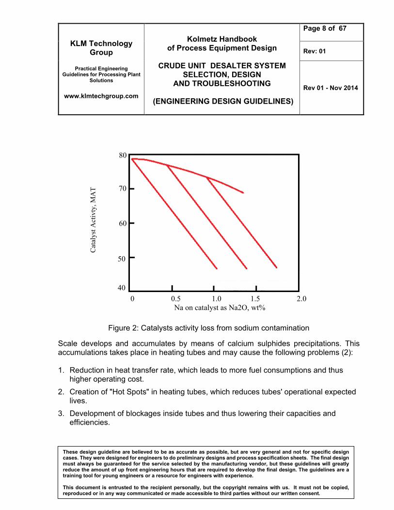
6. Metals from salts can also cause catalyst deactivation and sintering which result in
lower catalyst activity. Sodium has been found to be the most harmful metal for catalysts
Metals from salts can also cause catalyst deactivation and sintering which result in lower catalyst activity. Sodium has been found to be the most harmful metal for catalysts. This decrease in activity implies that used catalyst must be replaced more often to maintain a given activity level.
KLM Technology Group
Practical Engineering
Guidelines for Processing Plant Solutions
www.klmtechgroup.com
Kolmetz Handbook
of Process Equipment Design
CRUDE UNIT DESALTER SYSTEM SELECTION, DESIGN
AND TROUBLESHOOTING
(ENGINEERING DESIGN GUIDELINES)
Page 8 of 67
Rev: 01
Rev 01 - Nov 2014
These design guideline are believed to be as accurate as possible, but are very general and not for specific design cases. They were designed for engineers to do preliminary designs and process specification sheets. The final design must always be guaranteed for the service selected by the manufacturing vendor, but these guidelines will greatly reduce the amount of up front engineering hours that are required to develop the final design. The guidelines are a training tool for young engineers or a resource for engineers with experience. This document is entrusted to the recipient personally, but the copyright remains with us. It must not be copied, reproduced or in any way communicated or made accessible to third parties without our written consent.
Figure 2: Catalysts activity loss from sodium contamination
Scale develops and accumulates by means of calcium sulphides precipitations. This accumulations takes place in heating tubes and may cause the following problems (2): 1. Reduction in heat transfer rate, which leads to more fuel consumptions and thus
higher operating cost.
2. Creation of "Hot Spots" in heating tubes, which reduces tubes' operational expected lives.
3. Development of blockages inside tubes and thus lowering their capacities and efficiencies.
0 0.5 1.0 1.5 2.0
Na on catalyst as Na2O, wt%
Cat
aly
st A
ctiv
ty,
MA
T
50
40
60
70
80
KLM Technology Group
Practical Engineering
Guidelines for Processing Plant Solutions
www.klmtechgroup.com
Kolmetz Handbook
of Process Equipment Design
CRUDE UNIT DESALTER SYSTEM SELECTION, DESIGN
AND TROUBLESHOOTING
(ENGINEERING DESIGN GUIDELINES)
Page 9 of 67
Rev: 01
Rev 01 - Nov 2014
These design guideline are believed to be as accurate as possible, but are very general and not for specific design cases. They were designed for engineers to do preliminary designs and process specification sheets. The final design must always be guaranteed for the service selected by the manufacturing vendor, but these guidelines will greatly reduce the amount of up front engineering hours that are required to develop the final design. The guidelines are a training tool for young engineers or a resource for engineers with experience. This document is entrusted to the recipient personally, but the copyright remains with us. It must not be copied, reproduced or in any way communicated or made accessible to third parties without our written consent.
The amount of salt going into the charge furnace must be controlled to minimize corrosion in the downstream equipment. Since facilities are designed for a specific corrosion allowance it is critical that salt and corrosion to be controlled and to stay at or below the design limits. The purpose of desalting is to remove contaminants from crude oil before it enters the processing units. By removing the contaminants at the onset it is possible to minimize corrosion and fouling in downstream units. Refiners usually desalt the entering crude to less than 1 PTB (lb salt/1000 bbl) or the salt content on crude. Desalting in the field reduces corrosion downstream while the crude is transported either in pipelines or tankers. In addition the desalted water can, after suitable treatment, be re-injected back into the reservoir. This solves any environmental problems. Desalting which follows the initial dehydration or emulsion breaking, consist of (4):
1. Adding dilution (or less saline) water to the crude
2. Mixing this dilution water with the crude to dilute the sediment and water (S&W) droplets in the crude
3. Dehydration (emulsion treating) to separate the crude oil and diluted brine (S&W) phases.
The result is to dilute the original S&W droplets and so reduce the salt content (PTB) for comparable levels of crude dehydration (remnant vol % S&W). Desalting can be performed in a single stage or in two stages, depending on the requirements of the refinery. Dehydration efficiency of a Desalter is usually 95% in a single stage and up to 99% in two stages (5).
KLM Technology Group
Practical Engineering
Guidelines for Processing Plant Solutions
www.klmtechgroup.com
Kolmetz Handbook
of Process Equipment Design
CRUDE UNIT DESALTER SYSTEM SELECTION, DESIGN
AND TROUBLESHOOTING
(ENGINEERING DESIGN GUIDELINES)
Page 10 of 67
Rev: 01
Rev 01 - Nov 2014
These design guideline are believed to be as accurate as possible, but are very general and not for specific design cases. They were designed for engineers to do preliminary designs and process specification sheets. The final design must always be guaranteed for the service selected by the manufacturing vendor, but these guidelines will greatly reduce the amount of up front engineering hours that are required to develop the final design. The guidelines are a training tool for young engineers or a resource for engineers with experience. This document is entrusted to the recipient personally, but the copyright remains with us. It must not be copied, reproduced or in any way communicated or made accessible to third parties without our written consent.
The conventional equipment required for stage desalting includes:
1. A free-water knockout (FWKO) or heater treater for the initial brine removal or emulsion treating.
2. A tee for injecting the dilution water.
3. A mixing device to co-mingle the dilution water with the S&W drops entrained in the brine
4. A second treater (nearly always an electrostatic heater treater) to separate the crude and the dilution water.
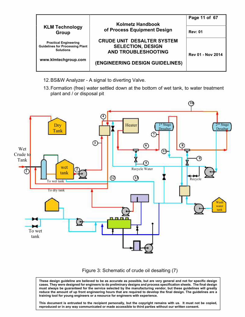
When designing a Desalter, its type and size are all dependent on a number of operational factors such as required pressure, temperature, viscosity and flow rate, as well as user specification relating to maximum salt amount (PTB) allowed in the product oil stream. Figures 1 below shows a schematic of crude oil desalting respectively (6). A typical process scheme is illustrated as follows:
1. Wet crude flow to wet tank.
2. Demulsifier / Chemical injection.
3. Crude flow to heat exchanger.
4. Flow to heater.
5. Wash water recycled from 2nd stage vessel.
6. Flow to 1st stage desalting mixing valve.
7. Mixed fluid to 1st stage vessel.
8. Flow to 2nd stage desalting mixing valve.
9. Fresh water from water-water heat exchanger originated from wash water tank.
10. Treated crude flow.
11. Effluent water from 1st stage Desalter vessel to water treatment plant and / or disposal pit.
KLM Technology Group
Practical Engineering
Guidelines for Processing Plant Solutions
www.klmtechgroup.com
Kolmetz Handbook
of Process Equipment Design
CRUDE UNIT DESALTER SYSTEM SELECTION, DESIGN
AND TROUBLESHOOTING
(ENGINEERING DESIGN GUIDELINES)
Page 11 of 67
Rev: 01
Rev 01 - Nov 2014
These design guideline are believed to be as accurate as possible, but are very general and not for specific design cases. They were designed for engineers to do preliminary designs and process specification sheets. The final design must always be guaranteed for the service selected by the manufacturing vendor, but these guidelines will greatly reduce the amount of up front engineering hours that are required to develop the final design. The guidelines are a training tool for young engineers or a resource for engineers with experience. This document is entrusted to the recipient personally, but the copyright remains with us. It must not be copied, reproduced or in any way communicated or made accessible to third parties without our written consent.
12. BS&W Analyzer - A signal to diverting Valve.
13. Formation (free) water settled down at the bottom of wet tank, to water treatment plant and / or disposal pit
Figure 3: Schematic of crude oil desalting (7)
To wet
tank
Wash
water tank
wet
tank
To wet tank
To dry tank
Wet
Crude to
Tank
2nd Stage
Desalter
Recycle
Heater
Recycle Water
Dry
Tank
1st Stage
Desalter
1 2
3
4
10
7
6
5
12 13
11
8
9
KLM Technology Group
Practical Engineering
Guidelines for Processing Plant Solutions
www.klmtechgroup.com
Kolmetz Handbook
of Process Equipment Design
CRUDE UNIT DESALTER SYSTEM SELECTION, DESIGN
AND TROUBLESHOOTING
(ENGINEERING DESIGN GUIDELINES)
Page 12 of 67
Rev: 01
Rev 01 - Nov 2014
These design guideline are believed to be as accurate as possible, but are very general and not for specific design cases. They were designed for engineers to do preliminary designs and process specification sheets. The final design must always be guaranteed for the service selected by the manufacturing vendor, but these guidelines will greatly reduce the amount of up front engineering hours that are required to develop the final design. The guidelines are a training tool for young engineers or a resource for engineers with experience. This document is entrusted to the recipient personally, but the copyright remains with us. It must not be copied, reproduced or in any way communicated or made accessible to third parties without our written consent.
From figure 1 above, an emulsion comprises of water and oil flows to a wet tank. a common emulsion may contain up to 25% water cut. Water and salt of the crude must be reduced to 0.10% vol. and 5.0 PTB in typical Desalting/Dehydration Plant, respectively (TPL, 1992). A two-stage desalting system is used to remove such large quantities of water from the oil stream. The emulsion, leaves the wet tank, where the primary water separation takes place (stream 2). Chemical/demulsifier is injected into the stream prior to feed pumps. After settling for a period of several hours, formation water (stream 13) flows to waste water treatment plant or disposed to a designated disposal pit. In stream 3, emulsion flow from the wet tank to a heat exchanger, where heat is recovered from the treated crude product stream 10. The emulsion then flows to a water-bath indirect heater, raising its temperature (stream 4). Water recycled from 2nd stage vessel (stream no. 5) injected into the emulsion flow coming out of the heater. At the mixing valve (no. 6), recycled water and emulsion agitated by an induced shearing force. The operation of a mixing valve is carried out by a simple globe valve where an operator would set the differential pressure across the valve to be as high as possible ensuring better mixing of the two fluids. The mixing fluid enter to 1st stage Desalter where emulsion is exposed to a high voltage electrostatic field. the electrostatic field coalesces the dispersed water phase and gravity causes the enlarged water droplets to fall and collect in the bottom of the vessel then leaves the system to a wastewater treatment plant or the disposal pit (stream 11). This effluent water contains various impurities and salts removed from the water-in-oil emulsion. Treatment of an emulsion (still contains salt water) is further enhanced in the second stage desalting vessel (stream 8) and mixed with fresh water (stream 9). treated emulsion is introduced near the bottom of the 2nd stage partially and travels upward through an electrical voltage grids. In this stage, water droplets are enlarged by means of high voltage electrostatic field and separated by gravity. The separated water is collected at the bottom of the vessel and recycled to the first stage Desalter (stream 5), while the treated crude flows from the top of the vessel (stream no. 10). Desalter sizing is strongly influenced by viscosity which is dependent on the operating temperature. A Desalter feed temperature of at least 70˚C should be allowed in the design
KLM Technology Group
Practical Engineering
Guidelines for Processing Plant Solutions
www.klmtechgroup.com
Kolmetz Handbook
of Process Equipment Design
CRUDE UNIT DESALTER SYSTEM SELECTION, DESIGN
AND TROUBLESHOOTING
(ENGINEERING DESIGN GUIDELINES)
Page 13 of 67
Rev: 01
Rev 01 - Nov 2014
These design guideline are believed to be as accurate as possible, but are very general and not for specific design cases. They were designed for engineers to do preliminary designs and process specification sheets. The final design must always be guaranteed for the service selected by the manufacturing vendor, but these guidelines will greatly reduce the amount of up front engineering hours that are required to develop the final design. The guidelines are a training tool for young engineers or a resource for engineers with experience. This document is entrusted to the recipient personally, but the copyright remains with us. It must not be copied, reproduced or in any way communicated or made accessible to third parties without our written consent.
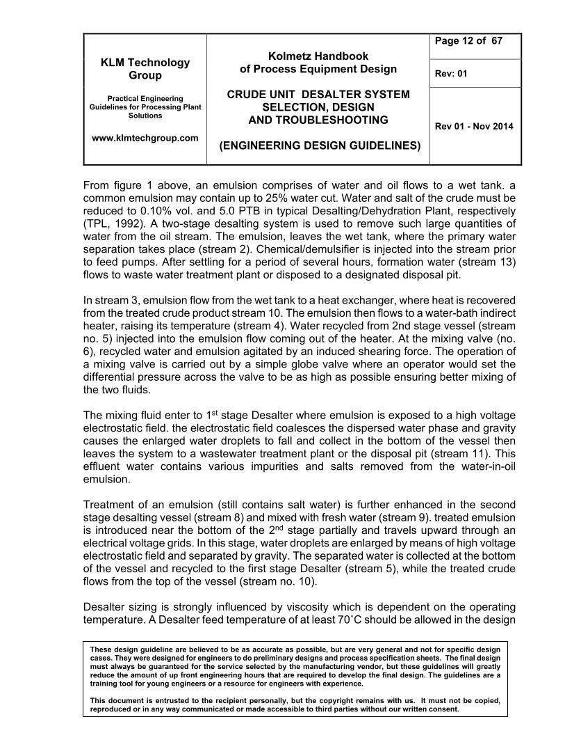
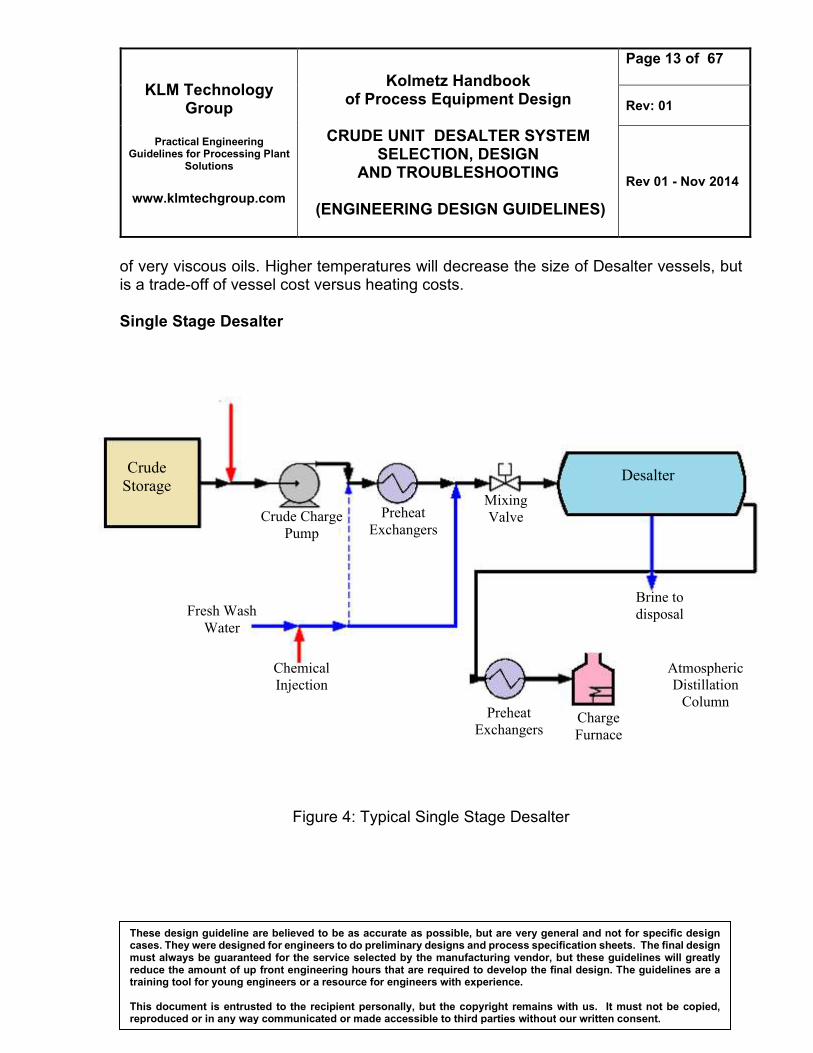
of very viscous oils. Higher temperatures will decrease the size of Desalter vessels, but is a trade-off of vessel cost versus heating costs. Single Stage Desalter
Figure 4: Typical Single Stage Desalter
Crude
Storage
Crude Charge
Pump
Preheat
Exchangers
Mixing
Valve
Desalter
Brine to
disposal Fresh Wash
Water
Chemical
Injection
Preheat
Exchangers Charge
Furnace
Atmospheric
Distillation
Column
KLM Technology Group
Practical Engineering
Guidelines for Processing Plant Solutions
www.klmtechgroup.com
Kolmetz Handbook
of Process Equipment Design
CRUDE UNIT DESALTER SYSTEM SELECTION, DESIGN
AND TROUBLESHOOTING
(ENGINEERING DESIGN GUIDELINES)
Page 14 of 67
Rev: 01
Rev 01 - Nov 2014
These design guideline are believed to be as accurate as possible, but are very general and not for specific design cases. They were designed for engineers to do preliminary designs and process specification sheets. The final design must always be guaranteed for the service selected by the manufacturing vendor, but these guidelines will greatly reduce the amount of up front engineering hours that are required to develop the final design. The guidelines are a training tool for young engineers or a resource for engineers with experience. This document is entrusted to the recipient personally, but the copyright remains with us. It must not be copied, reproduced or in any way communicated or made accessible to third parties without our written consent.
Crude oil is typically brought into a refinery by pipeline and goes to the raw crude tanks. This can be a single tank or multiple tanks with various different crude blended together. Ideally the crude charge tanks will have continuous mixers but some facilities operate with static tanks which is not advisable since it does not allow for a fully blended feed. The crude is then pumped to be heated into a series of heat exchanges against hot overhead and product side streams in the Crude Unit prior to entering the Desalter to a temperature of anywhere from 230-300F depending on the type of crude and the facility. At a preheat temperature of about 200–250◦F water is injected into the crude to dissolve salt that is usually present. The mixture enters a Desalter drum usually containing an electrostatic precipitator. The salt water contained in the crude is separated by means of this electrostatic precipitation. The water phase from the drum is sent to a sour-water stripper to be cleaned before disposal to the oily water sewer. The crude is then desalted and leaves the Desalter at 190 F then send through another set of exchanges, then into a crude charge furnace which is leaves at 600 F and finally into the crude unit distillation column. The desalting process works by mixing raw crude oil with water in a mix valve with a high differential pressure. This causes the water and oil to form an emulsion with the salt mostly dissolved in the water phase. During mixing, salt content in oil is washed with the water and a W/O emulsion is formed. This emulsion is then broken in the Desalter by use of gravity, heat, electrical energy and chemical additives. If mixing is good, dehydration efficiency can be compared with desalting efficiency as most of the salt passed from the organic phase into the water phase. In actual operation, water and oil are preheated and mixed in a 1:20 ratio. It is common that a demulsifier substance is also added, usually 0.005 to 0.01 lb/barrel [6]. Mixture takes place in a mixing device, which is commonly a valve with a 5 to 20 psi pressure drop. It has been observed that good mixing allows for appropriate salt removal from oil.
KLM Technology Group
Practical Engineering
Guidelines for Processing Plant Solutions
www.klmtechgroup.com
Kolmetz Handbook
of Process Equipment Design
CRUDE UNIT DESALTER SYSTEM SELECTION, DESIGN
AND TROUBLESHOOTING
(ENGINEERING DESIGN GUIDELINES)
Page 15 of 67
Rev: 01
Rev 01 - Nov 2014
These design guideline are believed to be as accurate as possible, but are very general and not for specific design cases. They were designed for engineers to do preliminary designs and process specification sheets. The final design must always be guaranteed for the service selected by the manufacturing vendor, but these guidelines will greatly reduce the amount of up front engineering hours that are required to develop the final design. The guidelines are a training tool for young engineers or a resource for engineers with experience. This document is entrusted to the recipient personally, but the copyright remains with us. It must not be copied, reproduced or in any way communicated or made accessible to third parties without our written consent.
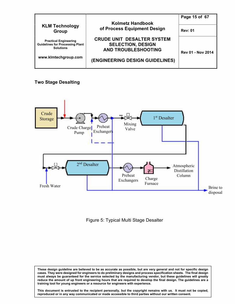
Two Stage Desalting
Figure 5: Typical Multi Stage Desalter
Crude
Storage
Crude Charge
Pump
Preheat
Exchangers
Mixing
Valve
1st Desalter
Brine to
disposal
Fresh Water
Preheat
Exchangers Charge
Furnace
Atmospheric
Distillation
Column
2nd Desalter

KLM Technology Group
Practical Engineering
Guidelines for Processing Plant Solutions
www.klmtechgroup.com
Kolmetz Handbook
of Process Equipment Design
CRUDE UNIT DESALTER SYSTEM SELECTION, DESIGN
AND TROUBLESHOOTING
(ENGINEERING DESIGN GUIDELINES)
Page 16 of 67
Rev: 01
Rev 01 - Nov 2014
These design guideline are believed to be as accurate as possible, but are very general and not for specific design cases. They were designed for engineers to do preliminary designs and process specification sheets. The final design must always be guaranteed for the service selected by the manufacturing vendor, but these guidelines will greatly reduce the amount of up front engineering hours that are required to develop the final design. The guidelines are a training tool for young engineers or a resource for engineers with experience. This document is entrusted to the recipient personally, but the copyright remains with us. It must not be copied, reproduced or in any way communicated or made accessible to third parties without our written consent.
The techniques of emulsion breaking (demulsifier injection, heating, phase separation of any vapor or pressure stabilization, and electrostatic coalescence) may be required If co-mingling the crude and dilution water produces a stable emulsion In single desalting, the required dilution water injection rate is usually 5-7% of the crude flow rate. Field desalting is often required in regions where fresh water is the scarcest. Two stage desalting usually reduces the dilution water required to 1-2%of the crude flow rate.

KLM Technology Group
Practical Engineering
Guidelines for Processing Plant Solutions
www.klmtechgroup.com
Kolmetz Handbook
of Process Equipment Design
CRUDE UNIT DESALTER SYSTEM SELECTION, DESIGN
AND TROUBLESHOOTING
(ENGINEERING DESIGN GUIDELINES)
Page 17 of 67
Rev: 01
Rev 01 - Nov 2014
These design guideline are believed to be as accurate as possible, but are very general and not for specific design cases. They were designed for engineers to do preliminary designs and process specification sheets. The final design must always be guaranteed for the service selected by the manufacturing vendor, but these guidelines will greatly reduce the amount of up front engineering hours that are required to develop the final design. The guidelines are a training tool for young engineers or a resource for engineers with experience. This document is entrusted to the recipient personally, but the copyright remains with us. It must not be copied, reproduced or in any way communicated or made accessible to third parties without our written consent.
DEFINITIONS Gravity separation - refers to the primary free settling of water and is related to the residence time that takes place in both settling tanks and desalting vessels. AC – Alternating electrical current Desalination - Process of removing salts from water sources Fouling – The reduction in performance of process equipment (heat transfer tubing, membranes, etc.) that occurs as a result of scale buildup, biological growth, or the deposition of colloidal material. Membrane – In desalting, used to describe a semipermeable film. Membranes used in electrodialysis are permeable to ions of either positive or negative charge. Reverse osmosis and nanofiltration membranes ideally allow the passage of pure water and block the passage of salts Precipitate – A substance separated from a solution by chemical or physical change as an insoluble amorphous or crystalline solid. Saline water – Water with dissolved solids exceeding the limits of potability. Saline water may include sea water, brackish water, mineralized ground and surface water, and irrigation return flows. Salt diffusion – The movement of ions or molecules under influence of a concentration difference. Solubility – A measure of the maximum amount of a certain substance that can dissolve in a given amount of water, or other solvent, at a given temperature. Specific conductance (conductivity) – Quantitative expression for the capability of a particular solution to conduct electricity. It is defined as the conductance of a cube of that particular water that is 1 cm long and has a cross sectional area of 1 cm2. Conductivity is usually expressed in micromohos per centimeter.
KLM Technology Group
Practical Engineering
Guidelines for Processing Plant Solutions
www.klmtechgroup.com
Kolmetz Handbook
of Process Equipment Design
CRUDE UNIT DESALTER SYSTEM SELECTION, DESIGN
AND TROUBLESHOOTING
(ENGINEERING DESIGN GUIDELINES)
Page 18 of 67
Rev: 01
Rev 01 - Nov 2014
These design guideline are believed to be as accurate as possible, but are very general and not for specific design cases. They were designed for engineers to do preliminary designs and process specification sheets. The final design must always be guaranteed for the service selected by the manufacturing vendor, but these guidelines will greatly reduce the amount of up front engineering hours that are required to develop the final design. The guidelines are a training tool for young engineers or a resource for engineers with experience. This document is entrusted to the recipient personally, but the copyright remains with us. It must not be copied, reproduced or in any way communicated or made accessible to third parties without our written consent.
Stage – A unit of desalting equipment capable of purification and separation of the feed water into product and concentrate. If separation is insufficient, more than one stage can be arranged in series Turbidity – Opaqueness or cloudiness caused by the presence of suspended particles in water, usually stirred-up sediments. The turbidity of a water is measured by its capacity for absorbing or scattering light. S&W content – Oil, as produces from the well and production equipment, may contain considerable amounts of brine, as well as solid materials. The water solids content is refferes to as sediment and water (S&W) or basic sediment and water (BS&W). Demulsifier – or demulsifying chemicals are a mixture of chemicals used to break the emulsion by destroying a weakening the stabilizing film around the dispersed droplets. Electrodes or grid – plates or rods used to establish the electric field in electrostatic treaters. Electrostatic treater - treater using electric fields in the oil coalescing area. Emulsifier - in addition to oil and water, a third substance called an emulsifier or emulsifying agent must be present for a stable emulsion to be produced. The emulsifiers usually exist as a film on the surface of the dispersed droplets. Emulsion – a combination of two immiscible liquids. One liquid is broken into droplets and is known as the discontinuous, dispersed, or internal phase. The liquid that surrounds the drops is continuous or external phase. Interface – the contact surface between the boundaries of the two immiscible liquids (e.g., the surface area between water droplets and the surrounding oil or the surface between separated crude and water in a vessel. Water-in-oil (w/o) emulsion – Crude oil emulsions nearly always consist of water drops dispersed in a continuous oil phase. This type is also called a regular or normal emulsion
KLM Technology Group
Practical Engineering
Guidelines for Processing Plant Solutions
www.klmtechgroup.com
Kolmetz Handbook
of Process Equipment Design
CRUDE UNIT DESALTER SYSTEM SELECTION, DESIGN
AND TROUBLESHOOTING
(ENGINEERING DESIGN GUIDELINES)
Page 19 of 67
Rev: 01
Rev 01 - Nov 2014
These design guideline are believed to be as accurate as possible, but are very general and not for specific design cases. They were designed for engineers to do preliminary designs and process specification sheets. The final design must always be guaranteed for the service selected by the manufacturing vendor, but these guidelines will greatly reduce the amount of up front engineering hours that are required to develop the final design. The guidelines are a training tool for young engineers or a resource for engineers with experience. This document is entrusted to the recipient personally, but the copyright remains with us. It must not be copied, reproduced or in any way communicated or made accessible to third parties without our written consent.
Desalting – Reducing the salt content of a crude oil by diluting the entrained/emulsified water and then dehydrating. Dehydration – Removing water droplets or S&W or BS&W from crude oil (sometimes called treating) Oil-in-water (o/w) emulsion – an emulsion consisting of oil drops disperse in a continuous water phase. This do-called reverse emulsion often occurs on waste waters and produced brines. The water content is generally greater than 85 volume percent. Wetting – refers to the adhesion or sticking of a liquid to a solid surface. If the solid surface (grain of reservoir rock, fines, etc) is covered preferentially by oil, the surface is called oil wetted. Conversely, if water is preferentially attracted, the surface is water wetted.
KLM Technology Group
Practical Engineering
Guidelines for Processing Plant Solutions
www.klmtechgroup.com
Kolmetz Handbook
of Process Equipment Design
CRUDE UNIT DESALTER SYSTEM SELECTION, DESIGN
AND TROUBLESHOOTING
(ENGINEERING DESIGN GUIDELINES)
Page 20 of 67
Rev: 01
Rev 01 - Nov 2014
These design guideline are believed to be as accurate as possible, but are very general and not for specific design cases. They were designed for engineers to do preliminary designs and process specification sheets. The final design must always be guaranteed for the service selected by the manufacturing vendor, but these guidelines will greatly reduce the amount of up front engineering hours that are required to develop the final design. The guidelines are a training tool for young engineers or a resource for engineers with experience. This document is entrusted to the recipient personally, but the copyright remains with us. It must not be copied, reproduced or in any way communicated or made accessible to third parties without our written consent.
NOMENCLATURE A Water in inlet stream, bbl B Water in clean oil, bbl C water to Desalter inlet, bbl Cso the salt content of the oil, lbm/1,000 bbl; Csw the concentration of salt in produced water, ppm; d diameter of droplet E Mixing efficiency, % E1 Mixing efficiency of V with A as fraction, % E2 Mixing efficiency of Y with B as fraction, % Ec critical voltage gradient Ef electric field gradient, m ɛo permittivity of free space, farad/m ɛoil dielectric constant of crude oil Fd drop flow, m3/s Fd* drop flow at current operating temperature, m3/s Fe electrostatic force, N FO(in) oil inflow, m3/year fw the volume fraction of water in crude oil. FW(in) water inflow, m3/year FW(out)* water outflow at current operating temperature, m3/ year g Gravity, m/s2 h distance covered by the drop, m. K Dielectric constant for the system K1 Salt per barrel of water to facility, lb K2 Salt per barrel of dilution water, lb K3 Salt per barrel of water to Desalter inlet, lb K4 Salt per barrel of water to second stage Desalter, lb R water to second stage Desalter, bbl RWO water/oil feed ratio. S Water to first stage Desalter, bbl SGw the specific gravity of produced water T Clean (water-free)crude volume, bbl V Recycle water to injection in first stage inlet line, bbl
KLM Technology Group
Practical Engineering
Guidelines for Processing Plant Solutions
www.klmtechgroup.com
Kolmetz Handbook
of Process Equipment Design
CRUDE UNIT DESALTER SYSTEM SELECTION, DESIGN
AND TROUBLESHOOTING
(ENGINEERING DESIGN GUIDELINES)
Page 21 of 67
Rev: 01
Rev 01 - Nov 2014
These design guideline are believed to be as accurate as possible, but are very general and not for specific design cases. They were designed for engineers to do preliminary designs and process specification sheets. The final design must always be guaranteed for the service selected by the manufacturing vendor, but these guidelines will greatly reduce the amount of up front engineering hours that are required to develop the final design. The guidelines are a training tool for young engineers or a resource for engineers with experience. This document is entrusted to the recipient personally, but the copyright remains with us. It must not be copied, reproduced or in any way communicated or made accessible to third parties without our written consent.
V Water to disposal, bbl Vd volume of water drop, m3. VS Settling rate, m/s x center-to-center distance drops, m X1 fraction of water in produced oil stream X2 Fraction of water in clean oil outlet X3 Fraction of water in second stage outlet oil Y Injection water of lesser salinity than inlet water, bbl Z Salt in outlet clean oil/1000 barrels of net oil, lb Greek Leters η dehydration efficiency θd drop’s residence time, s ρO density of oil, kg/m3 ρW density of water, kg/m3 σ surface tension µO dynamic viscosity of oil, kg/m s. Superscript A Water in inlet stream, bbl B Water in clean oil, bbl C water to Desalter inlet, bbl E Mixing efficiency, % Y Injection water of lesser salinity than inlet water, bbl Z Salt in outlet clean oil/1000 barrels of net oil, lb