Embed Size (px)
Citation preview

Guidelines for District Heating Substations
Approved by the Euroheat & Power Board Prepared by Task Force Customer Installations
EUROHEAT & POWER
Guidelines for District Heating Substations
October 2008
Disclaimer: It should be noted, however, that the guidelines cannot cover all the possible special cases in which further
or restrictive measures may be required. In the same line of thinking, they are not intended to hinder the development of new and better
products. Applying the guidelines does not absolve anyone of responsibility for their own actions. Accordingly, Euroheat & Power disclaims any responsibility for any
consequence caused by the application of the guidelines by its members or third parties. Nor can Euroheat & Power be held responsible for any advice given by the TF Customer Installations in this respect.

TABLE OF CONTENTS
CHAPTER 1 – GENERAL ....................................................................................................................... 1
1.1. PURPOSE OF THE GUIDELINES ..................................................................................................................................1
1.2. APPROVAL OF THE SYSTEM AND EQUIPMENT ...........................................................................................................2
1.3. UNITS USED ...........................................................................................................................................................2
1.4. TECHNICAL DATA OF THE DISTRICT HEATING SYSTEM..............................................................................................3
1.4.1. Operating forward temperature........................................................................................................................ 3
1.4.2. Importance of low return temperature or cooling of the network ................................................................ 4
1.4.3. Differential pressure ............................................................................................................................................ 4
1.4.4. Quality of water used for district heating systems .......................................................................................... 5
CHAPTER 2 – THE DOMESTIC WARM WATER SYSTEM .......................................................................... 8
2.1. TEMPERATURES, ENVIRONMENTAL AND HEALTH REQUIREMENTS ON THE SECONDARY SIDE ......................................8
2.2. HEAT EXCHANGERS.................................................................................................................................................9
2.2.1. Types of heat exchangers (in general and for domestic warm water production) ...................................... 9
2.2.2. Storage tanks ....................................................................................................................................................... 9
2.3. DWW CONTROL SYSTEM.......................................................................................................................................12
2.4. DOMESTIC WARM WATER CIRCULATION SYSTEM .....................................................................................................12
2.5. CHOICE OF MATERIALS ..........................................................................................................................................13
2.6. HEAT EXCHANGERS, DIMENSIONING TEMPERATURES, PRESSURES AND DIFFERENTIAL PRESSURES ...........................14
2.7. DIMENSION AND CAPACITIES ................................................................................................................................14
2.7.1. Determining flow capacities for domestic warm water ...............................................................................14 2.7.2. Advantages with correct dimensions on valves and not substantially oversized dimensions on heat
exchangers ...................................................................................................................................................................17
CHAPTER 3 – RADIATOR AND VENTILATION SYSTEM ........................................................................ 18
3.1. TYPES OF HEAT EXCHANGERS................................................................................................................................18
3.2. FUNCTIONAL REQUIREMENTS................................................................................................................................18
3.3. CHOICE OF MATERIALS FOR HEATING AND VENTILATION SYSTEMS .........................................................................18
3.4. RADIATOR AND VENTILATION CONTROL SYSTEM ...................................................................................................19
3.5. DIMENSIONING OF HEAT EXCHANGERS FOR RADIATOR SYSTEMS AND VENTILATION SYSTEMS.................................19
3.5.1. Determining heat exchanger capacity ...........................................................................................................19
3.5.2. Capacity determination alternatives for radiator systems...........................................................................19
3.6. VALVES AND SENSORS .........................................................................................................................................21
CHAPTER 4 – PUMPS, SAFETY EQUIPMENT, VALVES, OTHER EQUIPMENT AND TEMPERATURE METERS
.................................................................................................................................................................................................22
4.1. PUMPS..................................................................................................................................................................22
4.1.1. General ...............................................................................................................................................................22
4.1.2. DWW circulation pumps ..................................................................................................................................22
4.1.3. Radiator and ventilation system circulation pumps .....................................................................................23
4.1.4. Pump control .....................................................................................................................................................23
4.2. DIFFERENTIAL PRESSURE DEVICES..........................................................................................................................23
4.3. SAFETY EQUIPMENT ..............................................................................................................................................23
4.3.1. Expansion vessels ..............................................................................................................................................23
4.3.2. Safety valves for DWW systems .......................................................................................................................24
4.3.3. Safety valves for radiator and ventilation systems .......................................................................................24
4.4. VALVES AND OTHER PIPING COMPONENTS ............................................................................................................25
4.4.1. General ...............................................................................................................................................................25
4.4.2. Check valves.......................................................................................................................................................26
4.4.3. Thermostatic Radiator Valve (TRV) and some importance features ...........................................................26
4.4.4. Hydraulic balancing and balancing valves....................................................................................................27
4.4.5. Shut-off valves ...................................................................................................................................................27
4.4.6. Drain, vent and pressure meter valves............................................................................................................27
4.4.7. Strainers (filters).................................................................................................................................................28
4.4.8. Temperature meters..........................................................................................................................................28
4.4.9. Pressure meters..................................................................................................................................................28
4.5. MARKING OF HEAT EXCHANGERS AND SUBSTATIONS .............................................................................................29
CHAPTER 5 – CONNECTION PRINCIPLES ............................................................................................ 30
5.1. GENERAL DESCRIPTION OF THE MINIMUM STANDARD............................................................................................30
5.2. DIRECT AND INDIRECT CONNECTION .....................................................................................................................32
5.3. 1-STEP AND 2-STEP CONNECTION OF DOMESTIC WARM WATER............................................................................33
5.4. SYSTEMS OF DOMESTIC WARM WATER..................................................................................................................34
5.5. VARIOUS CONNECTION ALTERNATIVES..................................................................................................................36
CHAPTER 6 – SERVICE AND MAINTENANCE ....................................................................................... 43
CHAPTER 7 – HEAT METERING .......................................................................................................... 48
7.1. GENERAL ..............................................................................................................................................................48
7.2. FUNCTIONAL REQUIREMENTS ................................................................................................................................49
7.2.1. Temperature sensors ........................................................................................................................................50
7.2.2. Flow sensor........................................................................................................................................................51
7.2.3. Calculator ..........................................................................................................................................................51
7.2.4. Remote reading of data ...................................................................................................................................53
7.3. DOCUMENTATION REQUIREMENTS.........................................................................................................................53
7.3.1. General ..............................................................................................................................................................53
7.3.2. Compatibility and interfaces between subassemblies.................................................................................54
7.4. DIMENSIONING OF TEMPERATURE SENSORS ...........................................................................................................54
7.5. DIMENSIONING OF FLOW SENSORS........................................................................................................................54
7.5.1. The district heating system..............................................................................................................................55
7.5.2. Heat demand ...............................................................................................................................................55
7.5.3. Selection of suitable flow sensors ...................................................................................................................57
7.6. INSTALLATION OF HEAT METERS............................................................................................................................58
7.6.1. Environmental influences.................................................................................................................................58
7.6.2. Planning the meter position............................................................................................................................58
7.6.3. Suitable and unsuitable positions for flow sensors .................................................................................60
7.6.4. Piping installation ............................................................................................................................................60
7.6.5. Electrical installation........................................................................................................................................61
7.6.6. Identity checking ..............................................................................................................................................62
7.6.7. Installation inspection .....................................................................................................................................62
7.7. EVALUATION OF CONFORMITY WITH THE MID REQUIREMENTS ...............................................................................63
7.7.1. Examination of type and design .....................................................................................................................65
7.7.2. Inspection of produced meters .......................................................................................................................65
7.7.3. Control systems.................................................................................................................................................65
7.7.4. Re-verification of meters..................................................................................................................................66
7.8. LIFETIME COST ......................................................................................................................................................67

1
CHAPTER 1 – GENERAL
1.1. Purpose of the Guidelines
The present guidelines contain a set of recommendations focusing on planning, installation,
use and maintenance of district heating (DH) substations within district heating systems
throughout Europe.
The recommendations were developed in order to enable readers to develop well-functioning
substations and an effective heat and domestic warm water delivery.
These guidelines are intended to give the most effective overall solutions for various parts of
the customer installation. The guidelines are not meant to specify the different components of
the substation such as meters or heat exchangers.
The guidelines deal with a wide variety of issues concerning both present systems of today and
district heating systems of the future. Specific handling and maintenance recommendations are
mainly focused on present modern systems but are also intended to cover the future situation
as much as is feasible. For this reason, certain existing systems are not dealt with in these
guidelines. For instance, these guidelines do not cover steam systems, systems with
temperatures exceeding 110 °C and pressure levels above 1.6 MPa.
The guidelines include a chapter on the heat meter, as the meter and especially the meter
installation is always installed simultaneously with the rest of the substation.
These guidelines aim to provide best-practice and easy-to-handle recommendations for:
� those who are responsible for relations between district heating utilities and customers;
� those who own or maintain a building connected to the district heating network;
� those who manufacture, plan, purchase, test and install substations.
These guidelines do not deal with investment or cost aspects, but in general, Euroheat & Power
recommends looking at the lifetime cost of all components of the substation, instead of
investment costs alone. An example of this is provided in Chapter 7.8.
The Guidelines were developed based on the most optimal operating principles of substations
and meters. Nevertheless, when national regulations pose rules contrary to those
recommended in the guidelines, these regulations should in all cases prevail. For instance,
throughout most countries in Europe prescriptions exist in order to avoid risks of diseases like
Legionella. The officially prescribed temperatures should in every case prevail over
temperatures taken up in these recommendations. At the same time however, the guidelines
demonstrate that the harmonization of various rules and regulations throughout Europe,
including temperature levels, is both needed and feasible.

2
These guidelines are valid from 1 October 2008. The guidelines are to be regarded as a working
document subject to on-going adaptation and perfection.
1.2. Approval of the System and Equipment
All DH equipment and the system as a whole is to be approved in accordance with
international-, European Union (EU)-, and national laws, regulations, building codes and
standards. Also, all laws and rules from health and environmental authorities need to be taken
into consideration. National DH organisations and Euroheat & Power should make efforts
towards harmonizing such rules and standards throughout the EU, in order for these rules and
standards to be as much as possible in line with the specificities of DH. The aforementioned
organisations may also issue technical recommendations themselves.
The following standards and EU directives are relevant for the present Guidelines:
� Pressure Equipment Directive (97/23/EC)
� Measuring Instruments Directive (2004/22/EC)
� Energy Performance of Buildings Directive (2002/91/EC)
� Machinery Directive (2006/42/EC)
� Energy Services Directive (2006/32/EC)
� Eco-design Directive (2005/32/EC)
� EN/CEN standards: EN 1434, CEN 311, etc.
1.3. Units Used
1 kW = 0,86 Mcal/h = 102 kpm/s Capacity
1 kWh = 3600 kJ = 0,86 Mcal Energy
1 Mcal = 1,163 kWh = 4,1868 MJ Energy
1 l/s = 3,6 m3/h Flow
1 kPa = 0,01 bar = 0,1 mwp Pressure, Differential Pressure
10C = 10K Temperature
kv Flow coefficient value
kv = p
qv
∆ Flow coefficient value - definition
qv DH flow (m3/h)
∆p Dimensioning pressure difference, bar
β Authority of the control valve
hc
v
p
p
∆
∆=β Authority of the control valve – definition
∆pv Pressure loss of the selected valve, bar
∆phc Pressure loss of heating circuit, bar
HTS High Temperature Systems
LTS Low Temperature Systems

3
DWW Domestic Warm Water
DWWC Domestic Warm Water Circulation
SH Space Heating
DH District Heating
DHS District Heating Supply
DHR District Heating Return
DH water District Heating water
Storage tank Cylinder or accumulation vessel
1.4. Technical Data of the District Heating System
Traditional high-temperature systems (HTS) operate at higher temperatures and pressures than
low-temperature systems (LTS). Table 1 below shows rating and design data for the systems.
1.4.1. Operating forward temperature
The temperature curves in the diagram below show the supply temperatures from the
production plant to the district heating substations. It is important that the heat supplier clearly
specifies which operating temperature characteristic is employed. In order to ensure that
district heating substations receive a supply temperature of not less than 65°C, the forward
temperature of the water from the production plants should be about 10°C higher than the
targeted supply temperature.
Figure 1
Depending on local conditions, the break point can vary over the range -5oC to +10oC. Every DH
company should provide this information to the customer.

4
Operating and design data
Euroheat & Power strongly recommends DH companies to build all new systems, including new
parts in older systems, in accordance with the temperature and pressure levels provided below.
NOTE: Existing systems are not reflected in Table 1 below.
Table 1
District heating system Operating data Design data
High-temperature system
(HTS system)
100°C; 1,6 MPa
differential pressure 0,8 –
0,10 Mpa
110°C; 1,6 MPa
Low-temperature system
(LTS system)
Max 85°C; 0,6 MPa
differential pressure 0,35 –
0,3 MPa
90°C; 0,6 MPa
1.4.2. Importance of low return temperature or cooling of the network
The amount of heat utilised from the circulating district heating system water depends mainly
on the design and adjustment of the building's internal heating systems, but also on the
performance and the condition of the district heating substation. Good cooling of the district
heating water (i.e. more heat subtracted) and good performance of the district heating
substation are in the interests of both the customer and the heat supplier.
The quality of the circulation water that carries the heat can affect performance. Therefore,
water treatment and control and monitoring of contributory water for the system is important.
1.4.3. Differential pressure
The district heating supplier will provide information on the actual minimum and maximum
differential pressures, as measured at the service connection valves. This data should be used
for determining the necessary sizes and capacities of control valves and heat exchangers. Note
that the heat supplier should include the pressure drop across the heat meter in the
information provided.
The following diagram shows the principal ranges over which the differential pressure in a high
temperature district heating system can vary.
5
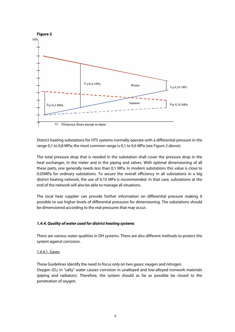
Figure 2
District heating substations for HTS systems normally operate with a differential pressure in the
range 0,1 to 0,8 MPa; the most common range is 0,1 to 0,6 MPa (see Figure 2 above).
The total pressure drop that is needed in the substation shall cover the pressure drop in the
heat exchanger, in the meter and in the piping and valves. With optimal dimensioning of all
these parts, one generally needs less than 0,1 MPa. In modern substations this value is close to
0.05MPa for ordinary substations. To secure the overall efficiency in all substations in a big
district heating network, the use of 0,10 MPa is recommended. In that case, substations at the
end of the network will also be able to manage all situations.
The local heat supplier can provide further information on differential pressure making it
possible to use higher levels of differential pressures for dimensioning. The substations should
be dimensioned according to the real pressures that may occur.
1.4.4. Quality of water used for district heating systems
There are various water qualities in DH systems. There are also different methods to protect the
system against corrosion.
1.4.4.1. Gases
These Guidelines identify the need to focus only on two gases: oxygen and nitrogen.
Oxygen (O2) in "salty" water causes corrosion in unalloyed and low-alloyed ironwork materials
(piping and radiators). Therefore, the system should as far as possible be closed to the
penetration of oxygen.
6
Nitrogen (N2) is an inactive gas in the water content and causes material problems when its
concentration is so high that free nitrogen gas bubbles are formed. Gas blistering appears as a
cause of increasing temperature and decreasing pressure. The gas solubility decreases.
Circulation disturbances, noise and erosion corrosion will be the consequences.
In district heating substations air/gas can permeate the circulation water through the expansion
tanks open to the atmosphere in the domestic system. Oxygen (and small amounts of nitrogen)
can enter through heat exchangers of domestic warm water systems, through diffusion from
permeable membranes or plastic pipe systems. Furthermore, low pressure conditions in closed
systems enable the entry of air through gaskets and automatic vacuum breakers.
1.4.4.2. Components in the water
Water soluble substances
Alkali
In warm water, alkali reacts with hydrogen carbonate forming calcium carbonate and resulting
in the formation of scale. Scale increase impedes the functioning of the heat exchanger and
decreases its thermal capacity. In some cases overheating occurs and as a consequence the
heat generator can be damaged. To protect the system against scale formation, the filling water
and top-up water should be softened.
Anions
Anions from water-soluble substances, particularly chloride and sulphates, in the presence of
oxygen lead to local corrosion (e.g. crack corrosion) with unalloyed ironwork materials.
A chloride concentration up to 50 mg/l will usually cause no corrosion damage. However, under
certain critical conditions (e.g. in case of increasing concentrations under covers, pores or in
columns), chloride ions in stainless steels can lead to pitting- and deposit corrosion. Due to the
fact that specific corrosion danger depends on several factors (e.g. material, medium, operating
conditions), a limit value valid for all operating conditions cannot be defined. In any case, a very
low chloride concentration is recommended. Also, chloride causes corrosion with aluminium
materials making this combination unadvisable.
Organic substances
Insoluble and soluble organic substances can impair water treatment technology, as well as
micro-biological reactions in the circulation water.
Oils and fats
To temporarily prevent the corrosion of old armatures, piping or heating surfaces, substances
based on oils or fats are used. As a film or cover on materials, oils affect the heat exchanger.
They also disturb the function of control- and safety equipment. Oils and fats are nutrients for
micro-organisms and can even cause micro-biological corrosion. Therefore it is strongly
recommended to avoid the use of oils and fats in DH systems.
7
1.4.4.3. Operating techniques
First of all, the system should be closed from air and cold water uptake to prevent corrosion.
Therefore suitable pressure maintenance is necessary. Another aspect is that magnetite - as a
corrosion product - builds a homogeneous oxygen surface layer with high corrosion resistance
on metallic surfaces. But this protection layer is only built at temperatures higher than 100°C. So
this effect cannot be used in domestic warm water systems.
Compliance with the standard values for chemical water treatment (see Table 2) unalloyed
ironwork materials, rustproof steels and coppers, separately or in combination, can be applied.
Aluminium or aluminium alloys should not be used in direct contact with the circulation water,
otherwise alkali-induced corrosion is possible.
Iron and copper can lead to deposits and failures in zones with low flows. Experience shows
that concentrations of iron ≤ 0,10 mg /l and copper ≤ 0,01 mg/l are in the normal range.
Euroheat & Power recommends not using aluminium at all in any DH systems, including the
secondary side.
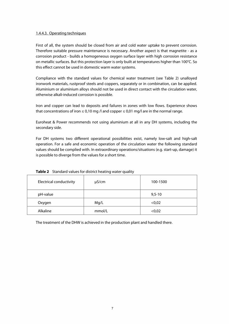
For DH systems two different operational possibilities exist, namely low-salt and high-salt
operation. For a safe and economic operation of the circulation water the following standard
values should be complied with. In extraordinary operations/situations (e.g. start-up, damage) it
is possible to diverge from the values for a short time.
Table 2 Standard values for district heating water quality
Electrical conductivity µS/cm 100-1500
pH-value 9,5-10
Oxygen Mg/L <0,02
Alkaline mmol/L <0,02
The treatment of the DHW is achieved in the production plant and handled there.

8
CHAPTER 2 – THE DOMESTIC WARM WATER SYSTEM
2.1. Temperatures, Environmental and Health Requirements on the
Secondary Side
With the entry into force of Directive 98/83/EC, European standards for ensuring the safety of
water for human consumption were enacted. The requirements for cold and warm water are
comparable with the demands on foodstuffs.
In order to achieve good comfort and health requirements for the domestic warm water system
one should be able to control:
� temperature levels on the secondary side;
� temperature of the circulation flow and return in the system.
It is advisable to check and record these parameters.
Bacteria and Legionella are not problems specific to district heating. They occur in all warm
water systems (heating oil/natural gas/solar/electric). The contamination of the system
especially with Legionella takes place in the domestic plant, i.e. in the drinking water pipe
system, the circulation and the storage tank.1 The owner of the domestic plant is responsible for
its good functioning.
In order to reduce the risk of Legionella infection, some special actions should be taken
regarding design and operation. Below, suggestions are presented on how to prevent the
development of bacteria and Legionella.
� “Short-cuts” or “dead ends” are to be prevented in the system.
� The domestic warm water system should not be used for other purposes than purely
sanitary; e.g. no connection of towel dryers or floor heating pipes to the drinking water
pipe system. Towel dryers and smaller floor heating pipes are potential risks for
bacteria.
� There should not be any connection of equipment to the system, which could force the
temperature below 50°C in any part of the system.
� For multi-family houses the outgoing temperature from the heat exchanger/ storage
tank should be minimum 55˚C in order to secure the temperature at the tap of 50˚C.
� For one-family houses, where the distances between the heat exchanger/storage tank
and the tap are typically short, minimum 50˚C at the heat exchanger is usually sufficient
to get a temperature of 50˚C at the tap as well.
� If accumulation of warm water in storage tanks is used, the system should be operated
at 55˚C. In case of Legionella growth in the system, the water content should be heated
up to at least 60˚C during two hours before the water is delivered to taps.
� Bacteria will not be eliminated by increasing the temperature to 55˚C in a heat
exchanger of warm water that has been standing still for a long time at 40˚C. Such
heating occurs very quickly and does not give sufficient time to kill the bacteria. This is

9
an unsuitable arrangement and does not meet public health and environmental
requirements.
� In buildings for especially sensitive persons like hospitals, retirement homes and
kindergartens special care should be taken to avoid growth of the Legionella bacteria. If
there are special demands for low temperatures at the tap or in a shower, fixed tap
positions with a maximum temperature of 38 ˚C should be installed. The mixing should
occur at the shower positions in order to avoid bacterial growth.
Water hardness
Euroheat & Power recommends not using any chemical treatment for water hardness.
2.2. Heat Exchangers
2.2.1. Types of heat exchangers (in general and for domestic warm water production)
Regardless of the type and the material of the heat exchanger, the basic objective is that heat
exchangers are to be dimensioned and built so that the customer will get sufficient warm water
in all normal circumstances. The cooling of DHW must be as effective as possible in all
conditions and all water flows should run along the heat exchange surfaces.
Modern heat exchangers are brazed plate heat exchangers. The heat exchanger surfaces are
made from acid-resistant steel or stainless steel. This type of exchanger has the advantages of
reliability, lightweight, and large capacity for its size. A disadvantage is the low internal water
volume, which may cause temperature problems if the regulating system is not fast enough. In
such cases it is recommended to change the control system to a faster one.
Another type of plate heat exchanger is plates with gaskets which can be used when problems
with lime scale occur. In such a case the manufacturer should guarantee the durability and
elasticity of gaskets and other elastic parts for operation (special attention should be paid to the
lifetime of the gaskets).
All heat exchangers used in district heating should follow the requirements of EN 1148.
2.2.2. Storage tanks
It is generally also possible to use DWW storage tanks if this is the traditional installation. Below
some examples are provided:
� if there is a lack of appropriate flow capacity of DH service connection (too small
dimension);
� if there is an exceptionally high use of DWW at the same moment (sport halls etc.);
� in low energy one-family houses.
1 ‘Storage tank’ is taken here to have the same meaning as ‘cylinder’.
10
It is more efficient for the cooling of the network to use substations without accumulation than
to use substations with accumulation.
The following examples show the dimensioning of DHW systems with storage tanks. The
diagrams are based on:
� DHW temperature 60 °C;
� Cold water temperature 10 °C;
� standard apartments.
2.2.2.1 One-family house system
One-family houses can use a storage tanks with 100 L – 160 L content, depending on the
number of inhabitants and their behaviour, the number of taps and the desired temperature
inside the storage tank.
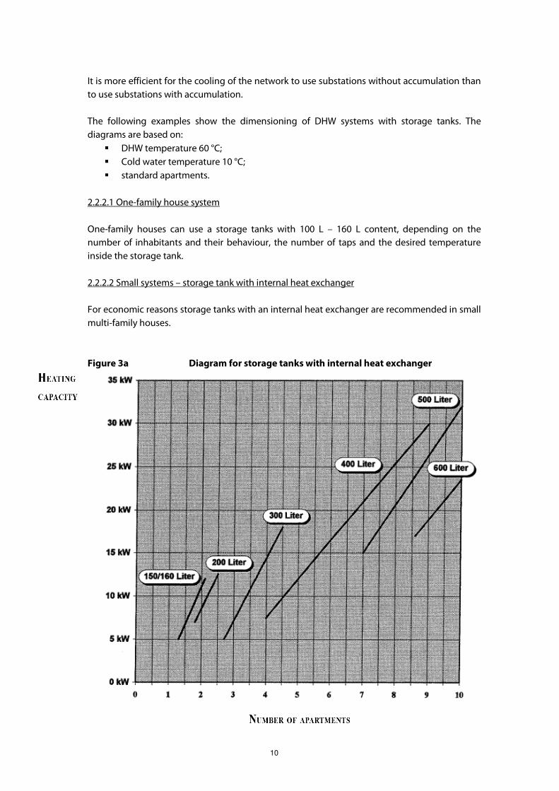
2.2.2.2 Small systems – storage tank with internal heat exchanger
For economic reasons storage tanks with an internal heat exchanger are recommended in small
multi-family houses.
Figure 3a Diagram for storage tanks with internal heat exchanger

11
Diagram corresponds to Figure 13 in connection drawings in Chapter 5.5.
Figure 3b Diagram for storage tanks combined with external heat
exchangers
Diagram corresponds to Figure 12 in connection drawings in Chapter 5.5.
The DWW tank size should guarantee the possibility of it being fully drained during daily
maximum consumption periods.
It is recommended to use a system consisting of a plate heat exchanger and a DWW storage
tank (flow-storage system) to obtain the lowest possible return temperatures from the
substation with storage tanks.
The DWW storage tank should have thermal insulation guaranteeing the maintenance of a
stable water temperature, which is necessary for an efficient filling pump. Filling the DWW
storage tank by means of a filling pump should not take more than two hours. The construction

12
shape of the DWW storage tank is to be of a vertical slim shape, which will ensure maximum
utilization capacity and a minimum dead sediment part.
2.3. DWW control system
The control system should ensure a stable DWW temperature during the whole year.
DWW may have priority over space heating, for instance, if based on limiting the maximum
substation capacity. One option in the control equipment could be to prioritize the DWW over
space heating. To guarantee the good quality of DWW a fast control system is needed, which
will keep the DWW temperature constant.
The following aspects should be considered when deciding on control equipment:
� pressure and temperature variations in the district heating system;
� detached house areas with central domestic warm water production;
� design and setting up of domestic warm water supply and circulation systems in order
to ensure circulation in all parts of the systems;
� whether the domestic warm water system does not have a circulation system (as in
detached house systems or apartment building systems);
� the type of heat exchanger;
� the frequency of warm water demand.
The control valves may be either electronically or temperature- or flow- controlled. In order to
ensure the best performance in 'on-demand' systems, the equipment should respond to both
the incoming cold water flow rate to the heat exchanger and the temperature of the domestic
warm water delivered from the heat exchanger.
2.4. Domestic warm water circulation system
The domestic warm water system consists of pipes from the heat exchanger in the substation to
the different taps and of circulation pipes which return unused water to the heat exchanger.
The task of the circulation of warm water is to keep the system active and the temperature on
such a level that both comfort and health requirements are satisfied for the customer.
Euroheat & Power recommends that circulation systems are used in all buildings that are
connected to district heating. If domestic warm water circulation systems are installed, which is
highly recommended especially in multi-family houses, one should ensure that the DWW return
temperature never goes below 50°C.
It is important that the domestic warm water circulation system maintains the prescribed
temperature in the distribution pipes and in the circulation pipes. This can be ensured through
a variable pump capacity, thermostatic valves and balancing valves.
13
In older buildings with no circulation systems, circulation should at least exist in the lowest part
that covers the horizontal pipes up to the vertical main pipes in multi-apartment buildings. If
there are significant distances in a one-family house Euroheat & Power recommends also
installing circulation there.
In order to avoid the waste of water and to improve comfort, it is recommended to design the
warm water system in such a way so that the warm water reaches the tap within approximately
10 seconds (design water flow: 0,2 l/sec.). In many cases, this means that the installation of a
circulation system is necessary. In cases where waiting time or the waste of water is not
important, for instance in rarely used taps, the circulation system or heat tracing can be
omitted. The recommendation of a 10 seconds maximum waiting time should not necessarily
result in the installation of circulation systems in all one-family houses.
2.5. Choice of materials
To ensure a safe and healthy production of domestic warm water there are a number of criteria
that should be fulfilled:
� the materials in question should be selected so that they can withstand the maximum
pressure that the system is designed for. In most systems this means 1.0 MPa pressure
on the tap water side and 1.6 (could also be 2.5 MPa) pressure on the primary side;
� the materials should also withstand the maximum temperature that the system is
designed for. This can vary considerably between different systems;
� the materials in question should not release harmful or poisonous substances into the
water;
� the materials in question should not contribute to the development of bacteria;
� if there is a mix of materials they should be chosen in a way to avoid galvanic corrosion
between the materials;
� water is the most common existing solvent and can in many cases be very aggressive.
When choosing materials for a domestic warm water system, attention should be paid
to the quality and chemical composition of the local water source to avoid corrosion of
the system;
� it is not only metals that are used in domestic warm water systems, but also polymers,
in gaskets, for example. The same care has to be taken in choosing gaskets for the
system; one should ensure that they can withstand the working conditions in the
system for the period the system is designed and that they do not add harmful or
poisonous substances to the water or contribute to the development of bacteria in the
water;
� common materials in domestic warm water systems are:
o Copper
o Stainless steel, i.e. 1.4301 (AISI 304), 1.4401 (AISI 316), 1.4404 (AISI 316L) or
Alloy 20/18/6
o Dezincified resistant brass
o Titanium
o Polymers
The choice of material in house installations should also follow national requirements and
regulations.
14
2.6. Heat Exchangers, Dimensioning Temperatures, Pressures and
Differential Pressures
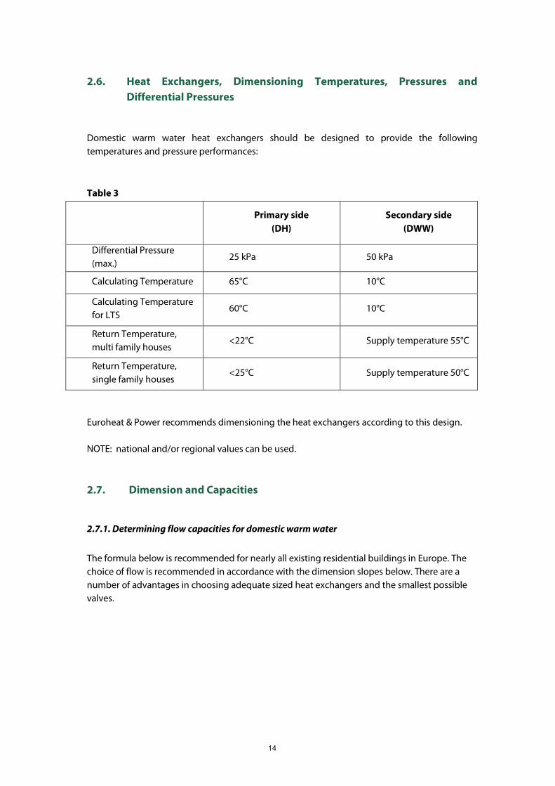
Domestic warm water heat exchangers should be designed to provide the following
temperatures and pressure performances:
Table 3
Primary side
(DH)
Secondary side
(DWW)
Differential Pressure
(max.) 25 kPa 50 kPa
Calculating Temperature 65°C 10°C
Calculating Temperature
for LTS 60°C 10°C
Return Temperature,
multi family houses <22°C Supply temperature 55°C
Return Temperature,
single family houses <25°C Supply temperature 50°C
Euroheat & Power recommends dimensioning the heat exchangers according to this design.
NOTE: national and/or regional values can be used.
2.7. Dimension and Capacities
2.7.1. Determining flow capacities for domestic warm water
The formula below is recommended for nearly all existing residential buildings in Europe. The
choice of flow is recommended in accordance with the dimension slopes below. There are a
number of advantages in choosing adequate sized heat exchangers and the smallest possible
valves.

15
Figure 4 Flow capacity for Domestic Warm Water for residential buildings
The two slopes represent the upper and lower flows that are currently used in Western and
Northern Europe for dimensioning of flow demand in residential buildings. By striving to make
dimensions closer to the lower line in Figure 4 above, one can obtain better economical and
maintenance results for both substations, network and production. See chapter 2.7.2.
The different flows are originally calculated by the following formula:
q q O n Q q A O q n Q qm m m m m m= + − + −( * ) * *
q = design flow rate [l/s] for n apartments
n = number of apartments
q m = 0,15 = aggregated flow per apartment to determine heat exchanger data
Q m = 0,20 = total maximum flow per apartment; may be increased if needed
O = 0,015 = probability of exceeding qm
A = 2,1 = probability of exceeding q
The figures entered refer to the lower slope in the graph.
Capacities of heat exchangers in residential buildings should be calculated and determined on
the basis of the following conditions:

16
Table 4
Number of
apartments
Domestic
warm water,
l/s
Number of
apartments
Domestic
warm water,
l/s
Number of
apartments
Domestic
warm water,
l/s
1 0,20 - 0,36 80 0,78 - 1,58 170 1,24 - 2,30
5 0,25 - 0,60 90 0,84 - 1,67 180 1,28 - 2,37
10 0,31 - 0,73 100 0,89 - 1,76 190 1,33 - 2,44
20 0,40 - 0,91 110 0,94 - 1,84 200 1,38 - 2,51
30 0,48 - 1,05 120 0,99 - 1,92 210 1,42 - 2,57
40 0,55 - 1,18 130 1,04 - 2,00 220 1,47 - 2,64
50 0,61 - 1,29 140 1,09 - 2,08 230 1,51 - 2,71
60 0,67 - 1,39 150 1,14 - 2,15 240 1,56 - 2,77
70 0,73 - 1,49 160 1,19 - 2,22 250 1,60 - 2,84
Several conditions must occur or be present simultaneously before a shortage is likely to arise:
� a district heating supply temperature of less than the normal minimum °C;
� differential pressure lower than the design minimum differential pressure;
� a cold water temperature lower than 10°C;
� a temperature drop of more than 5°C between the heat exchanger and the tap;
� a warm water flow rate exceeding ql/s as used in the above calculation.
In addition, the domestic warm water and circulation piping has a smoothing effect on the
domestic warm water temperature.
The required performance parameters for buildings with a recognised higher domestic warm
water demand, such as non-residential buildings, can be different, and should be specified.
High flow-rate tap water systems may be encountered in older buildings and allowance should
be made for them when deciding on the necessary flow-rate capacity of the heat exchanger.
If the system supplies more than 250 apartments, the requirements should be checked using
the formula above. In addition, it should be acknowledged that it is the heat exchanger for
which this formula intends to provide design data: rules for determining design capacities of
the domestic warm water system piping in the building(s) are set out in prEN 806-3;
Requirements for Systems and Components Inside Buildings Conveying Water for Human
Consumption - Part 3: Determining the Sizes of Tap Water Pipes.
The flows have been calculated from the following formula and are valid for apartment
buildings with more than five apartments. The 'single' apartment shown in Table 4 represents a
detached house or an individual apartment district heating substation unit. In many places in
Europe there are extensive residential areas with very big apartment buildings, some

17
containing more than 500 apartments per building. In some cases there is no good domestic
warm water circulation and this, and possible other circumstances, could demand higher flows
than calculated.
2.7.2. Advantages with correct dimensions on valves and not substantially oversized
dimensions on heat exchangers
Present dimensioning varies considerably throughout Europe. The advantages of using correct
dimensions, especially for valves, are the following:
� smoother and more dynamic network that better responds to changes in forward
temperature and flow. This means that the highest demands now are lower and easier
to supply than before. It also allows starting up the network after “a blow-out“ much
earlier than before;
� decreased morning peaks;
� less pumping costs;
� creating more capacity which can be used for new connections or transmission
purposes;
� better regulation of both warm water and heating in the substation means better,
smoother and more stable conditions. This leads to a longer lifetime for valves and
other equipment, less service costs and ensures a better economy to the owner of the
substation;
� the warm water circulation functions better;
� decreased risk for laminar flow when low flow conditions occur.
It can be concluded that by making the dimensions closer to the lower slope in Figure 4 above,
it is possible to obtain better economic and maintenance results for substations, the network
and production.

18
CHAPTER 3 – RADIATOR AND VENTILATION SYSTEM
3.1. Types of Heat Exchangers
Please refer to Chapter 2.2 (the same type of heat exchangers as for DWW except for shell and
tube heat exchangers).
3.2. Functional Requirements
Regardless of type and material of the heat exchanger, heat exchangers should be built so that
cooling of the DH water is as effective as possible in all conditions and so that all water flows
run along the heat exchange surfaces. Secondary supply water should not be mixed with
secondary return water. Heat exchangers should have thermal insulation and all connections
are to be clearly marked.
3.3. Choice of Materials for Heating and Ventilation Systems
To ensure safe and reliable operation a number of criteria should be fulfilled:
� the materials in question should be selected so that they can withstand the maximum
pressure the system is designed for. In most systems this means a 0.6 MPa pressure on
the heating/ventilation side and a 1.6 MPa (could also be 2.5 MPa) pressure on the
primary side;
� the materials should also withstand the maximum temperature that the system is
designed for. This can vary greatly between different systems.
� if there is a mix of materials they should be selected in such a way as to avoid galvanic
corrosion between these materials;
� water can be very aggressive in many cases. When choosing materials for a heating
system, care should be taken to the quality and chemical composition of the local water
source to avoid corrosion of the system;
� not only metals are used in heating systems, but also polymers in, for example, gaskets.
The same care has to be taken in choosing gaskets for the system, to ensure that they
can withstand the working conditions in the system for the period the system is
designed;
� common materials in heating systems are:
o Stainless steel, i.e. 1.4301(AISI 304), 1.4401(AISI 316), 1.4404(AISI 316L)
o Copper
o Carbon steel
o Dezincified resistant brass
o Polymers
19
3.4. Radiator and Ventilation Control System
The control system should assure stable space heating temperatures according to customer
needs during the whole year, independent of changes in the outside weather conditions or
inside heat loads. The preferred method is to use outside-temperature-compensated radiator
flow temperature (connected to the thermostatic radiator valves in every radiator). For this, the
outside temperature sensors should be placed in a suitable reference place (for instance the
northern wall). A flow water temperature sensor and a control centre should also be considered.
Modern control centers are digital with additional functions. Reference room temperature
sensors complement the outside temperature sensors.
If possible through agreement or ownership, it is advantageous to install a controller for DH or
other utilities with a temperature trend log that enables to register controllable parameters in
order to carry out technological optimization. Reference room temperature sensors are
recommended as an option. One should always pay attention to the cost-benefit situation.
3.5. Dimensioning of Heat Exchangers for Radiator Systems and
Ventilation Systems
3.5.1. Determining heat exchanger capacity
Heat exchanger capacity should be such that the heating power requirements of the building
can be met at the design outdoor temperature. In some cases, however, there may be an
operating mode that does not necessarily occur at the lowest ambient temperature that
determines the necessary design capacity. The local climatic conditions should also be
considered. Calculations should also be made to ensure that part-load power demands could
be met. Requirements resulting from the Buildings Directive and national applications for heat
demands should be taken into account.
Table 5 shows a number of alternatives for determining the necessary design capacities for
different types of building and heating systems. The specified return connection temperatures
apply for new heat exchangers with clean heat exchange surfaces.
3.5.2. Capacity determination alternatives for radiator systems
The design parameters used for the dimensioning of the radiator system are related to the DH-
system as a whole. The necessary DH supply temperature and the aimed return temperature
have a significant impact on the:
� heat losses;
� production efficiency;
� pipe capacity/construction cost;
� pumping capacity;
� the cost of heat installations.

20
In general, low temperature-set means less heat losses. The supply temperature is set by taking
into account: the fact that a low supply temperature means a demand for more pipe and
pumping capacity, whereas a low return temperature in all aspects is advantageous for the DH-
system. The only disadvantage of a low return temperature is that it demands a higher radiator
surface area. The design parameters for choosing the optimal return temperature are therefore
a compromise.
In general, the energy demand is decreasing. Specifically, the consumption for new buildings
has decreased. This increases the significance of having lower return temperatures, because a
smaller consumption rate leads to smaller radiators. In new one-family houses the focus on the
differential temperature is even more important in order to reduce the service pipe dimension,
resulting in lower construction costs and lower heat losses.
The necessary capacities of radiator systems in buildings already connected to a district heating
system, or for which such connection is planned, can be determined in accordance with Table 5.
Table 5 Target design temperature
Max. district
heating supply
temperature,
HT/LT system
Max. district
heating
return
temp.
Max.
radiator and
ventilation
system
supply temp.
Max.
radiator
and
ventilation
system
return
temp.
Max. floor
heating
system
temp.
Heating
systems 100/80°C 43°C 70°C 40°C 28 - 35°C
Ventilation
systems 100/80°C 33°C 60°C* 30°C
Max. pressure drop in district
heating side
Max. pressure drop in radiator and
ventilation side All systems
25 kPa 20 kPa
* 55°C for drier circuits
When the buildings are dimensioned for less optimal solutions (e.g. designed for using natural
gas boilers), the existing in-house radiator system will be used. It is preferable, however, to re-
design the existing system to suit the new conditions.
When considering 60-40°C or 70-30°C systems, the factors that particularly need to be
considered are the larger radiator surface areas and the lower flow rates, as well as the
improved temperature efficiency. It improves the efficiency of the district heating system and
reduces the return temperatures; the operation costs of the secondary system are in a heat
exchanger also lowered.

21
As with heat exchangers for domestic warm water systems, the temperature difference on the
return side of the radiator heat exchanger should not exceed 3°C at the design rating. At lower
loads, this temperature difference should be proportionally less. If the temperature difference
on the return side of the radiator heat exchanger is increased to 5°C at the design rating, this
will lead to a reduction of the heating surface of only 15%. The life-time cost of the system will
increase substantially as this will lead to increased pumping costs and increased return
temperature on the primary side.
Balancing the system has a decisive effect on operating performance, regardless of the choice
of design temperatures for the radiator circuit. Over the years, various principles have been
applied in order to achieve a good result: the high-flow and the low-flow principles, for
example, are two ways of achieving good cooling of the radiator circuit water.
There can be advantages in choosing a low-flow system for the building's heating system. A
characteristic of such systems is the relatively high design supply temperature and the low
return temperature, which assists the overall performance of the district heating system and
reduces costs in the whole system.
If a low-flow heating system providing very low return temperatures is used, there will be little
further benefit from the use of a two-stage connection in terms of further cooling of the return
water. In such cases, it is recommended that the more cost-efficient parallel connection should
be selected.
3.6. Valves and Sensors
Regulating valves are to be dimensioned according to the needs of space heating systems and
design values of the heat exchanger and heat flows:
� minimum pressure drop on open valves (valve authority) – should not be lower than
50% of the total pressure drop of the regulated unit.
Valve characteristics should consider the right consumption function. The valve should
minimize the risk of fissures and leaks from closed valves and should not exceed 0,05%Kvs at 1,0
MPa of pressure difference. Range ability of the valves should not be lower than 50:1 (control
ratio which is defined as a ratio between maximum flow to minimum controlled flow).
Temperature sensors
The time-constant of DWW temperature sensors is recommended to be maximum 2 seconds. In
order to ensure the correct measurement of temperature values, the proper construction and
installation of the temperature sensor is crucial. It is recommended to use an immersed casing
of stainless steel, operating in direct contact with the heating medium (with an additional
protective pocket) and installed in the pipeline axis. Pockets are only recommended for large
installations as compatibility is the greatest advantage for service purposes.

22
CHAPTER 4 – PUMPS, SAFETY EQUIPMENT, VALVES, OTHER EQUIPMENT
AND TEMPERATURE METERS
4.1. Pumps
4.1.1. General
Energy saving pumps should be considered in all circumstances in order to save energy and to
reduce the lifetime operation costs of the system. Such type of pumps enable the adjusted flow
to provide better conditions for space heating. The use of low energy pumps is strongly
recommended.
The manufacturer of the substation shall adjust the pressure (i.e. lifting height) of the pump in
accordance with the existing heat exchanger, as pressure drops could vary between design
specifications and manufacturers’ specifications.
For critical buildings (hospitals, retirement homes etc.) where it is very important to maintain
continuous and effective functioning, it is recommended to use double pumps with an
automatic start function for the second motor.
The class of electrical components, including motor, should be IP34 or higher.
It is recommended to use a voltage of 1x230 V.
All pumps in the system should have sufficiently low noise levels so that no noise is transferred
into the living quarters of the building.
The pump should be placed before the heat exchanger in order to reduce the risk of fissures
and reduce thermal stress of the electronic components.
4.1.2. DWW circulation pumps
The pump is to be designed for the same pressure and temperature class as the domestic water
system: PN 10 or higher. The wet part of the pump should be made of water-resistant materials
with a high oxygen content. The flow for DWW circulation pumps should be calculated on the
basis of both heat losses and pressure drops. Normally 20% of the total flow of the DWW heat
exchanger is utilized. DWW-circulation pipes should have a balancing valve in order to ensure
the correct flow for the DWW-network.
The circulation pump should be in continuous operation and is recommended to have speed
and noise control functions. It is also recommended to use adjustable DWW-pumps.

23
4.1.3. Radiator and ventilation system circulation pumps
The pump is to be designed for the same pressure and temperature class as the
radiator/ventilation system: PN 10 or higher.
The pumps should be dimensioned and selected in accordance with the secondary flow
through the heat exchanger.
4.1.4. Pump control
Pump control components are typically located inside the pump control box with terminal
connections. All pumps have to be protected against overload situations. This can be handled
inside the pump control box with overload protections or inside the pump motor. The pump
control box should be included in, at least, the main switch, in the switches for each motor, in
the indication lamps and in the alarm connection points for each pump motor.
In case of external switches for pump control, the pump control box should be equipped with
transmitters for controlled motors. This occurs, for instance, in the ECO-function in heating,
when pumps run intermittently during summer time via presostat or thermostat controlling.
The protection class of the pump control box should be IP34 or higher.
The pump control box should fulfil all local and national electricity requirements.
4.2. Differential Pressure Devices
For indirect systems with variations in differential pressures that are larger than 0.4 MPa and for
direct systems with variations larger than 0.1 MPa (and/or if noise occurs), it is an option to use
differential pressure devices.
The devices should be placed in the substation, or a part thereof, to avoid interaction between
differential pressure valves located in the same area.
A very high differential pressure may result in an additional systematical meter error.
4.3. Safety Equipment
4.3.1. Expansion vessels
Expansion vessels should be installed in closed loop systems to accommodate the thermal
expansion of the water. Dimensioning of the expansion vessel should be carried out by
considering both the possible difference between the highest and lowest temperatures that

24
could occur in the system and the total volume of the loop in question. For high buildings
(pressure <= 450 kPa) it is also possible to use systems with pressurisation sets, including
pumps, controls and expansion tanks.
The expansion pipe should be connected to the return pipe before the pump.
The expansion vessel should be placed on the suction side of the pump so that it need not also
control the pressure drop over the heat exchanger and the strainer.
Closed expansion systems are recommended in case of new installations due to the fact that
open systems can increase the oxygen level of domestic space heating systems.
When changing old installations, a check for the pressure level should be made.
It is necessary to control and measure the pressure of gas inside the expansion vessel.
4.3.2. Safety valves for DWW systems
The safety valve is to be installed in the cold water supply pipe connected to the domestic
warm water heater. There should not be any shut-off valve between the safety valve and the
water heater.
4.3.3. Safety valves for radiator and ventilation systems
The safety valve should preferably be installed in the incoming pipe to the heat exchanger on
the secondary side. There should not be any shut-off valve between the safety valve and heat
exchanger; otherwise one extra safety valve between the heat exchanger and shut-off valve will
have to be installed.
It is recommended to use two parallel safety valves on the space heating side in large buildings.
If a service shut-off valve is used for an expansion vessel, then the safety valve should be
installed between the heat exchanger and the service valve.
Pressure control
Euroheat & Power recommends the use of the same design parameters for pressure on the
primary side of the substation and for direct connections as the maximum system pressure of
the DH network.
If the design pressure of the DH network is higher than the parameters of the customer
installation, then special safety equipment has to be installed in accordance with the Pressure
Equipment Directive and/or local regulations.
An adequate resting pressure has to be ensured to prevent evaporation or vacuum formation.
The resting pressure is kept constant in the heat generating system, e.g. the power plant or
network substation.

25
The secondary side should be protected against excessive operating pressure by safety valves.
The design of safety valves and connection pipes should be done in accordance with the
Pressure Equipment Directive and national regulations.
4.4. Valves and Other Piping Components
4.4.1. General
It is recommended that the size of valves and other piping components be the same as the
pipes and be based on the flow.
The number of components and places are described in the connection principles under
Chapter 5.
Table 7 Materials and connections for all components
Primary side Domestic warm water Sec. Heating
Size DN 20 and
smaller
all sizes up to DN 50 all sizes up to DN 50 DN 65
and
higher
Material De-
zincification
proof brass,
cast iron,
carbon steel,
stainless
steel
De-
zincification
proof brass,
cast iron,
carbon steel,
stainless
steel
De-
zincification
proof brass,
stainless
steel
De-
zincification
proof brass,
stainless
steel
De-
zincification
proof brass,
cast iron,
carbon
steel,
stainless
steel
Cast
iron,
carbon
steel,
stainless
steel
Connection welded,
flanged,
threaded
welded,
flanged
threaded,
welded,
flanged
welded,
flanged
threaded,
welded,
flanged
welded,
flanged
Regulating valves for DWW should have a short closing time. Regulating valves for space
heating systems can have a longer closing time.

26
4.4.2. Check valves
Check valves should include an inspection hole in order to check for possible leakages.
Maximum pressure drop for check valves is recommended to be 3 kPa.
4.4.3. Thermostatic Radiator Valve (TRV) and some importance features
System improvements can be carried out by installing radiator thermostats (to control room
temperature), or hydraulic balancing valves (to balance the heating system and secure heat
distribution in buildings).
The thermostat radiator valve, consisting of a sensor unit and a valve body, automatically
controls the flow through the radiator in order to maintain the room temperature in accordance
with the desired and set value of the TRV.
For energy savings it is a possibility to have pre-programmed thermostat radiator valves. This
enables the room set point to be lowered and the forward temperature to the heating circuit to
be reduced.
Valve body
There are several types and sizes of valve bodies, e.g. straight and elbow. The sealing (gland
seal) around the spindle, which supports and guides the cone, is designed as one unit making it
easily exchangeable during operation.
Control unit
There are several kinds of control units. The most common are:
� control unit with a built-in thermostat sensor;
� control unit with a remote sensor, connected to the main control unit with a capillary
tube;
� control unit with a valve adaptor, connected to the remote setting unit with a capillary
tube.
Well-balanced heating systems where the room temperature is controlled by radiator
thermostats provide a highly energy efficient solution. In both 1-pipe and 2-pipe systems, they
result in considerable energy savings compared to unbalanced systems that are controlled by
manual valves.
By installing radiator thermostats on each radiator, two large energy saving gains are obtained:
1. By installing radiator valves that can be pre-set, the maximum flow through the radiator can
be limited to the actual amount needed to heat up the room, thereby reducing the amount of
water needed to flow in the system and the energy needed to run the pump.
2. By installing thermostats on each radiator, the room temperature will be controlled
automatically since the thermostat is a proportional controller, so the room temperature is kept
constant. It even cuts off the flow to the radiator when free heat (for example sunshine or bodily
warmth) is heating up the room.

27
4.4.4. Hydraulic balancing and balancing valves
An optimally controlled heating system has the following control performances:
� steady heat and pressure supply;
� awareness about sufficient heat authority by the use of balanced flow and presetting
facilities;
� controlling flow temperature according to changes in outdoor temperature;
� system balancing of flow and pressure and reducing influence from a change in load.
When designing an effective and energy efficient heating application, it will always be a great
advantage, regardless of the size of the installation/building, to install thermostatic radiator
valves with presetting as a minimum requirement and, in most cases, outdoor temperature
controls. In larger installations/buildings the hydraulic balancing valves (manual +
commissioning and automatic solutions) are a means of balancing flow and pressure in the
entire system.
Manual versus automatic hydraulic balancing valves have the following characteristics:
� manual balancing valves are cheaper than automatic types;
� manual balancing valves need additional work at starting-up, automatic types do not;
� manual balancing valves are an acceptable solution in many situations, but due to the
commissioning process which is set to average application conditions, larger changes
in the system are not accounted for. In such cases the automatic types provide for an
optimal solution.
Euroheat & Power recommends installing automatic hydraulic balancing valves.
Balancing valves
Balancing valves are to be installed on the secondary side of the space heating and DWW
circulation system in order to carry out hydraulic balancing of the internal installation. A
balancing valve can also function as a normal shut-off valve, if the balancing valve can fulfil the
same requirements set for shut-off valves. Drops in pressure should be easily measurable from
the valve.
4.4.5. Shut-off valves
Types of shut-off valves are ball valves or butterfly valves. Ball valves should be made of
stainless steel. Butterfly valves should be fitted with metal gaskets.
The use of grease or rubber gasket material for shut-off devices is unsuitable.
4.4.6. Drain, vent and pressure meter valves
Drain valves are assembled at the lowest point in all networks: primary side, DWW and
secondary heating side. These valves should be fitted with a removable plug. The size of a
draining valve should be DN 15. The connection type should be threaded.

28
Vent valves are assembled near the heat meter section at the primary side. These valves should
be fitted with a removable plug. The size of a draining valve should be DN 15. The connection
type should be threaded.
Pressure meter valves are assembled for each pressure meter in all networks: primary side,
DWW and secondary heating side. These valves should be fitted with an inspection connection.
The size of these valves should be DN 15 or in accordance with the meter connection. The
connection type should be threaded.
4.4.7. Strainers (filters)
Strainers should be fitted on the primary inlet at the secondary side to avoid foreign particles
passing into the system. It is recommended that the density of the mesh is to be between 0.5 -
1.0 mm. It should be equipped with a flushing valve for cleaning without dismantling the filter.
The drain pipe from filters should be suitable to ensure a thorough flushing of the filter. The
filter should be positioned in such manner that flushing the filter will not harm equipment. The
material of the mesh should be stainless steel.
4.4.8. Temperature meters
The temperature can be displayed either directly via a thermometer, or via a sensor. The range
of the temperature meters should at least cover the maximum temperature variations. The
reading accuracy of the meter should be at least 1°C.
4.4.9. Pressure meters
The clock diameter of a pressure meter should be >= 100 mm. For one-family houses smaller
clocks of around 50 mm can be used.
The reading accuracy of the meter should be at least 0.05 MPa. The meter should meet the
accuracy requirements of 1.6% of scale. Scale units should be MPa or bars. The measuring range
should be in accordance with the design pressure.
4.4.10 Booster pump
If the supply conditions are low and it is not economically practicable to raise the supply
conditions, there is the possibility of employing a booster pump.

29
4.5. Marking of Heat Exchangers and Substations
Heat exchangers should have a permanent and visible attached plate containing the following
information:
Manufacturer; Article No.; Type; Manufacturing No.; Manufacturing year; Minimum design
temperature; Maximum design temperature; Minimum design pressure; Maximum design
pressure; Test pressure; Volume per side; Fluid group; Directive 97/23/EC - PED Category or
article 3.3.
Substations should have a permanent and visible attached plate containing the following
information:
Manufacturer; Article No.; Type; Manufacturing No.; Manufacturing year; Design temperature;
Design pressure; Leakage test pressure; Volume per side; Safety valves settings; Heat load for
heating, ventilation and DWW; Temperature program for heating, ventilation and DWW;
Voltage; Fluid group; Directive 97/23/EC - PED Category or article 3.3.

30
CHAPTER 5 – CONNECTION PRINCIPLES
5.1. General Description of the Minimum Standard
These Guidelines include the most highly recommended connections with which to connect
customers to the primary network. Such connection principles are designed for the following
purposes:
� to ensure safe and reliable use;
� to maintain good quality of district heating;
� to minimize energy consumption;
� to simplify design work;
� to utilize the most cost efficient solutions.
The connection principles contain minimum standards that each substation should fulfil. It is
possible to add more functions and components to substations if the customer desires, or if
special conditions are present.
The connection principles are designed to ensure the most preferable means of cooling district
heating water. If better solutions are found from the cooling point of view, it is recommended
to use those.
In case of more than one heating network, substations should have their own heat exchanger
for each network. This applies, for example, to ventilation, floor heating and pool heating.
By-pass connections over the substation should not be used in the primary or secondary sides.
Such solutions decrease the cooling capacity of district heating water.
The recommended positions of components within the substation are exemplified in section 5
of this Chapter. The position of components can be modified for construction reasons.
Euroheat & Power recommends a connection drawing of the substation to be visible in every
heating room in multi-family houses.
Table 8 shows the main differences between the most common connection principles.

31
Table 8
DOMESTIC WARM WATER HEATING
Number of
Figure
Suitable
for district
heating
system
(see Table
1 in
Chapter
1.4.1)
Size of
building
Heat
exchanger
Pre-
heater
Storage
tank
Type of
connection
7 HTS, LTS Large Two stage
heat
exchanger
YES NO Indirect,
prim.
Return
temperatur
e >= 45°C
8 HTS, LTS Large One stage
heat
exchanger
NO NO Indirect,
prim.
Return
temperatur
e < 45°C
9 HTS, LTS Small house One stage
heat
exchanger,
max 60 kW
NO NO Indirect,
max 20 kW
10 HTS, LTS Large One stage
heat
exchanger
NO NO Direct
11 HTS, LTS Large One stage
heat
exchanger
NO YES Charging
system
12 LTS, Small house One stage
heat
exchanger,
max 40 kW
NO NO Direct, max
8 kW
13 LTS
Small house Heat
exchanger
inside tank,
max 25 kW
NO YES Direct, max
8 kW
The maximum capacities in small houses are 60 kW for DWW and 20 kW for heating.

32
5.2. Direct and Indirect Connection
Customers can be connected to the primary network using two main connection principles:
� indirect connection of the customer heating circuit to the district heating network: a heat
exchanger provides the hydraulic separation.
Figure 5
direct connection of the customer heating circuit to the district heating network. This principle
does not include any heat exchanger, so the same district heating water is inside the secondary
network (radiators, floor heating etc.). Directly connected systems are recommended to have
some kind of leakage alarm system.
Figure 6

33
Table 9 Design levels of indirect and direct connections
Indirect connection Direct connection
Design Temperatures up to 110°C less than 90°C – generally 80°C
Design pressures 1.6 MPa 0.6 MPa
Cooling of district heating
water
max 3°C higher as secondary
return temperature
same temperature as
secondary return
Differential pressure
controller normally not needed
needed to decrease pressure
in secondary side
Risk of damages and leakages no risks because of hydraulic
separated networks
Excessively high pressure may
cause pipe or radiator
damages and water leakage
5.3. 1-step and 2-step Connection of Domestic Warm Water
The main indirect connection principles of DWW are:
� one-step heat exchanger, including one part for DWW heating.
� two-step heat exchanger, including two parts for DWW heating: pre-heater and after-heater.
The district heating flow from space heating flows through the pre-heater of DWW and improves
the total cooling of the district heating system. The two-stage heat exchanger includes two parts
that are inside the same pressure vessel.
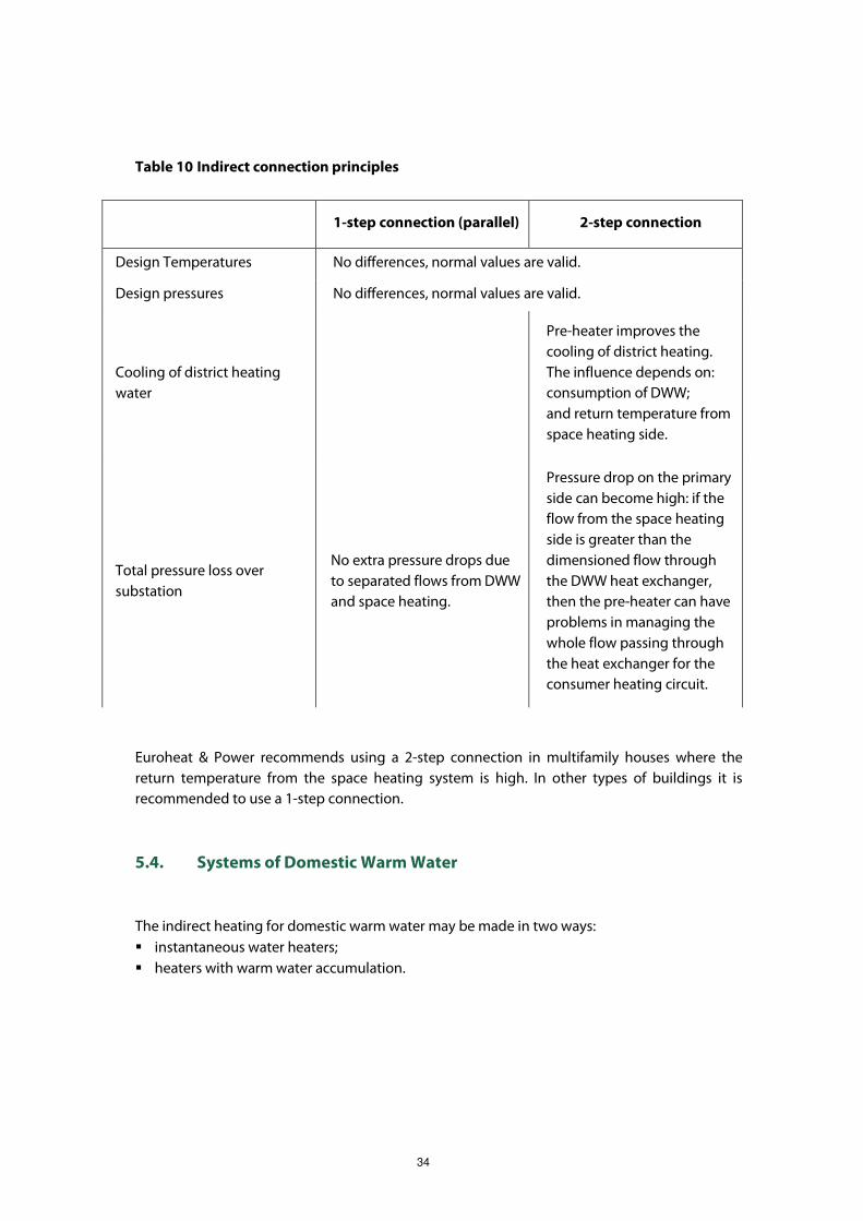
34
Table 10 Indirect connection principles
1-step connection (parallel) 2-step connection
Design Temperatures No differences, normal values are valid.
Design pressures No differences, normal values are valid.
Cooling of district heating
water
Pre-heater improves the
cooling of district heating.
The influence depends on:
consumption of DWW;
and return temperature from
space heating side.
Total pressure loss over
substation
No extra pressure drops due
to separated flows from DWW
and space heating.
Pressure drop on the primary
side can become high: if the
flow from the space heating
side is greater than the
dimensioned flow through
the DWW heat exchanger,
then the pre-heater can have
problems in managing the
whole flow passing through
the heat exchanger for the
consumer heating circuit.
Euroheat & Power recommends using a 2-step connection in multifamily houses where the
return temperature from the space heating system is high. In other types of buildings it is
recommended to use a 1-step connection.
5.4. Systems of Domestic Warm Water
The indirect heating for domestic warm water may be made in two ways:
� instantaneous water heaters;
� heaters with warm water accumulation.
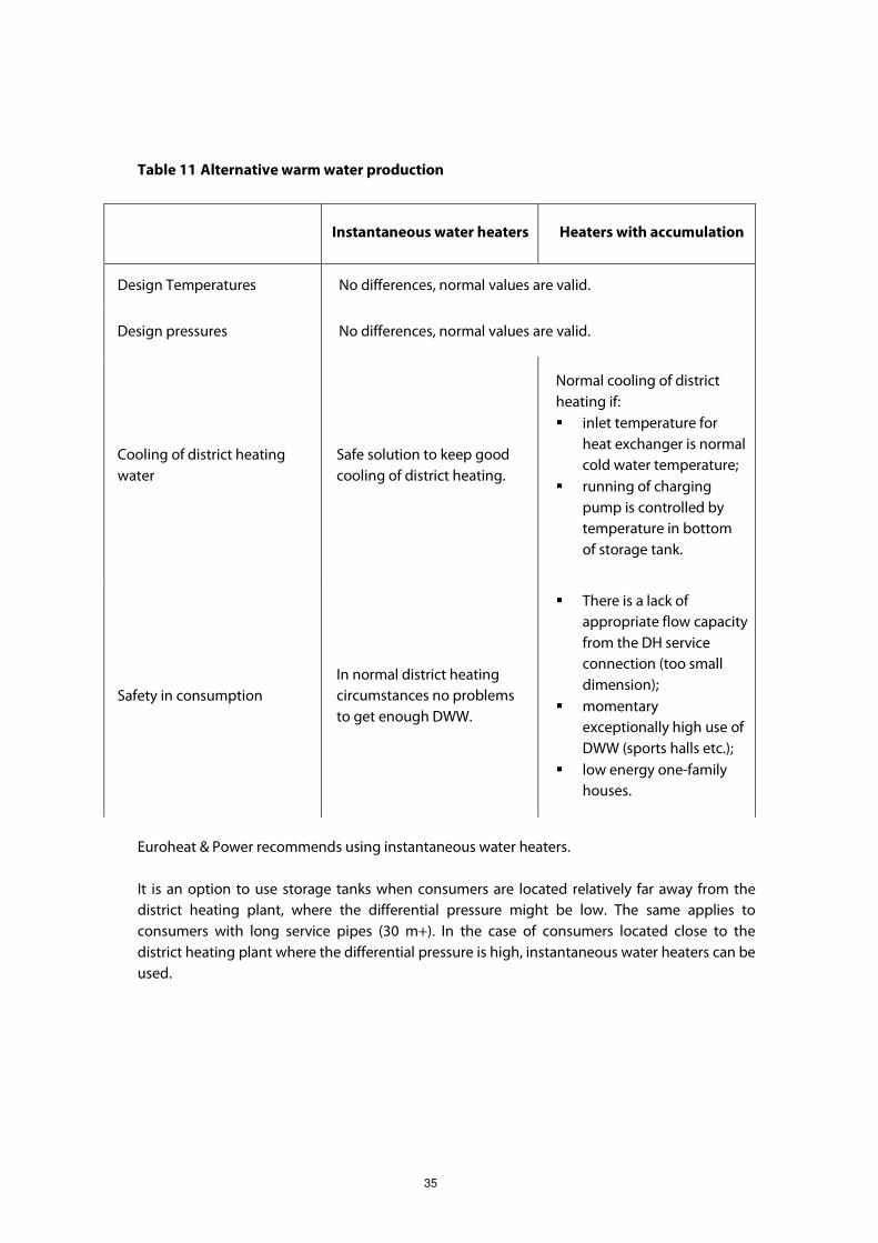
35
Table 11 Alternative warm water production
Instantaneous water heaters Heaters with accumulation
Design Temperatures No differences, normal values are valid.
Design pressures No differences, normal values are valid.
Cooling of district heating
water
Safe solution to keep good
cooling of district heating.
Normal cooling of district
heating if:
� inlet temperature for
heat exchanger is normal
cold water temperature;
� running of charging
pump is controlled by
temperature in bottom
of storage tank.
Safety in consumption
In normal district heating
circumstances no problems
to get enough DWW.
� There is a lack of
appropriate flow capacity
from the DH service
connection (too small
dimension);
� momentary
exceptionally high use of
DWW (sports halls etc.);
� low energy one-family
houses.
Euroheat & Power recommends using instantaneous water heaters.
It is an option to use storage tanks when consumers are located relatively far away from the
district heating plant, where the differential pressure might be low. The same applies to
consumers with long service pipes (30 m+). In the case of consumers located close to the
district heating plant where the differential pressure is high, instantaneous water heaters can be
used.

36
5.5. Various Connection Alternatives
Figure 7 Indirect 2-step

37
Figure 8 Indirect parallel

38
Figure 9 Indirect small house
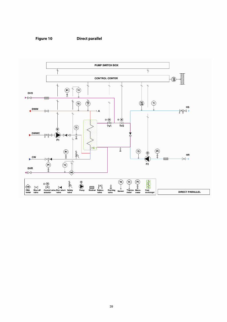
39
Figure 10 Direct parallel
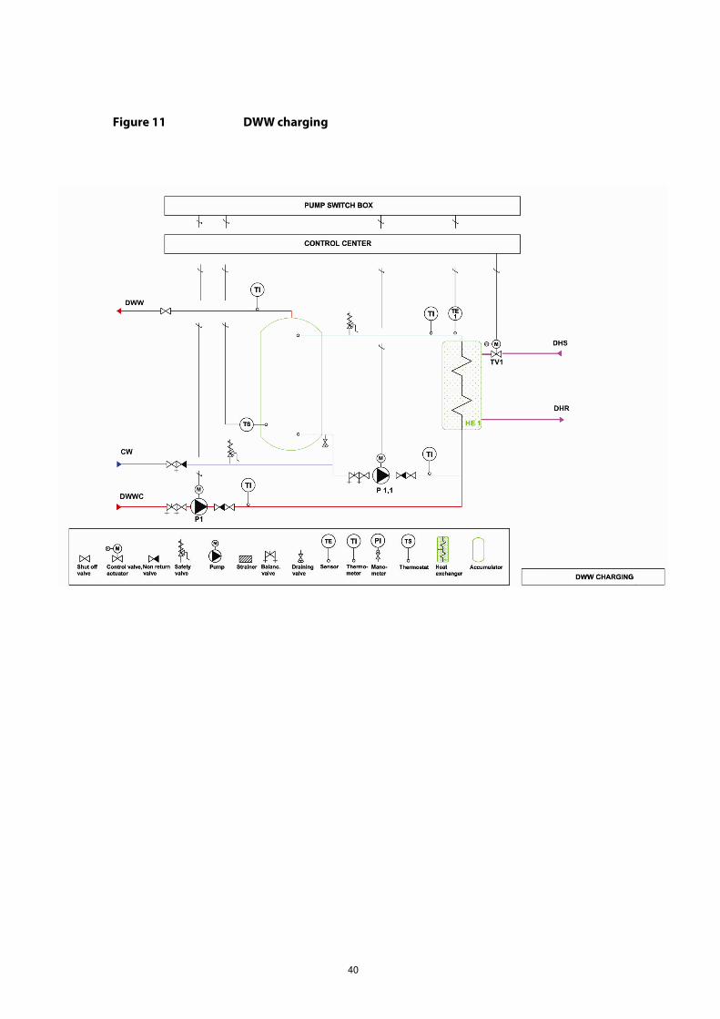
40
Figure 11 DWW charging

41
Figure 12 Direct parallel small house

42
Figure 13 DWW charging small house
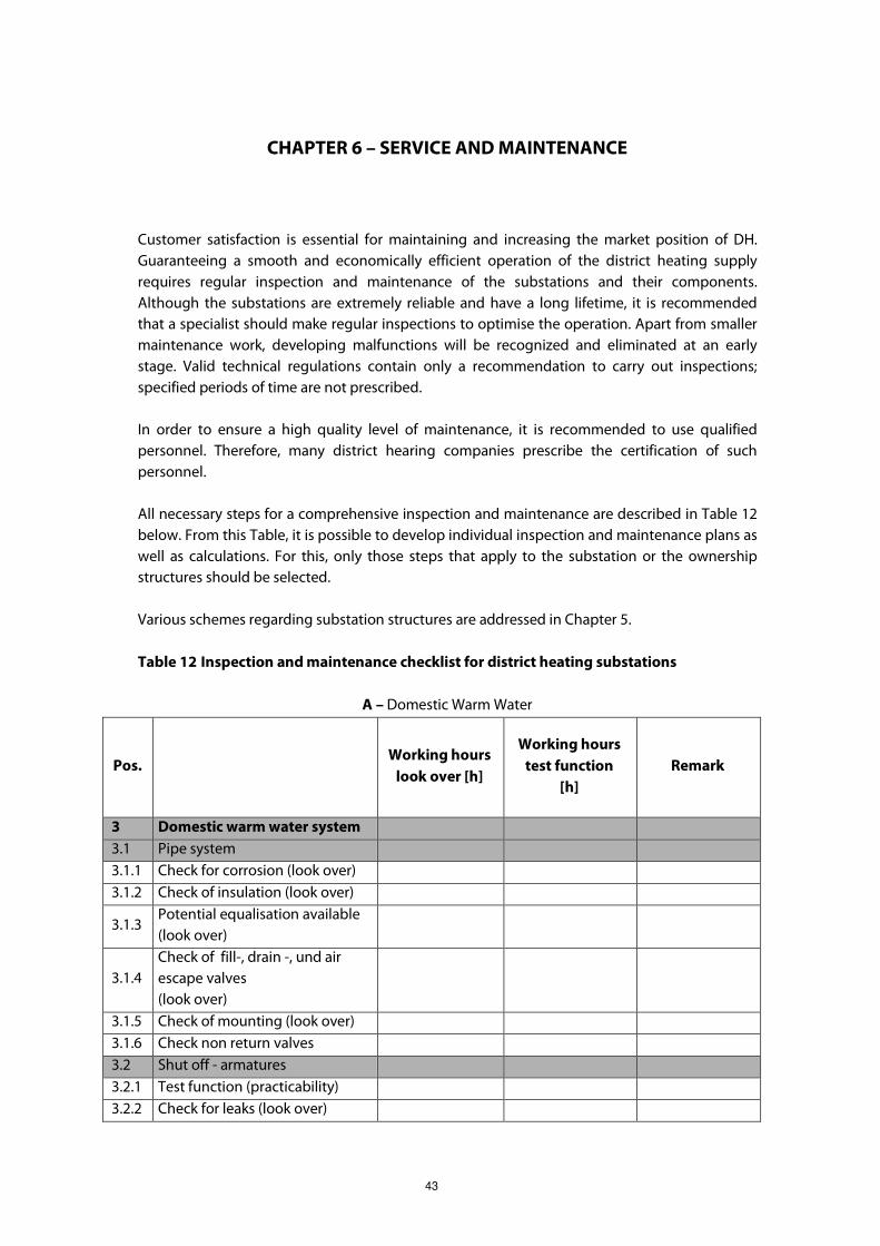
43
CHAPTER 6 – SERVICE AND MAINTENANCE
Customer satisfaction is essential for maintaining and increasing the market position of DH.
Guaranteeing a smooth and economically efficient operation of the district heating supply
requires regular inspection and maintenance of the substations and their components.
Although the substations are extremely reliable and have a long lifetime, it is recommended
that a specialist should make regular inspections to optimise the operation. Apart from smaller
maintenance work, developing malfunctions will be recognized and eliminated at an early
stage. Valid technical regulations contain only a recommendation to carry out inspections;
specified periods of time are not prescribed.
In order to ensure a high quality level of maintenance, it is recommended to use qualified
personnel. Therefore, many district hearing companies prescribe the certification of such
personnel.
All necessary steps for a comprehensive inspection and maintenance are described in Table 12
below. From this Table, it is possible to develop individual inspection and maintenance plans as
well as calculations. For this, only those steps that apply to the substation or the ownership
structures should be selected.
Various schemes regarding substation structures are addressed in Chapter 5.
Table 12 Inspection and maintenance checklist for district heating substations
A – Domestic Warm Water
Pos. Working hours
look over [h]
Working hours
test function
[h]
Remark
3 Domestic warm water system
3.1 Pipe system
3.1.1 Check for corrosion (look over)
3.1.2 Check of insulation (look over)
3.1.3 Potential equalisation available
(look over)
3.1.4
Check of fill-, drain -, und air
escape valves
(look over)
3.1.5 Check of mounting (look over)
3.1.6 Check non return valves
3.2 Shut off - armatures
3.2.1 Test function (practicability)
3.2.2 Check for leaks (look over)
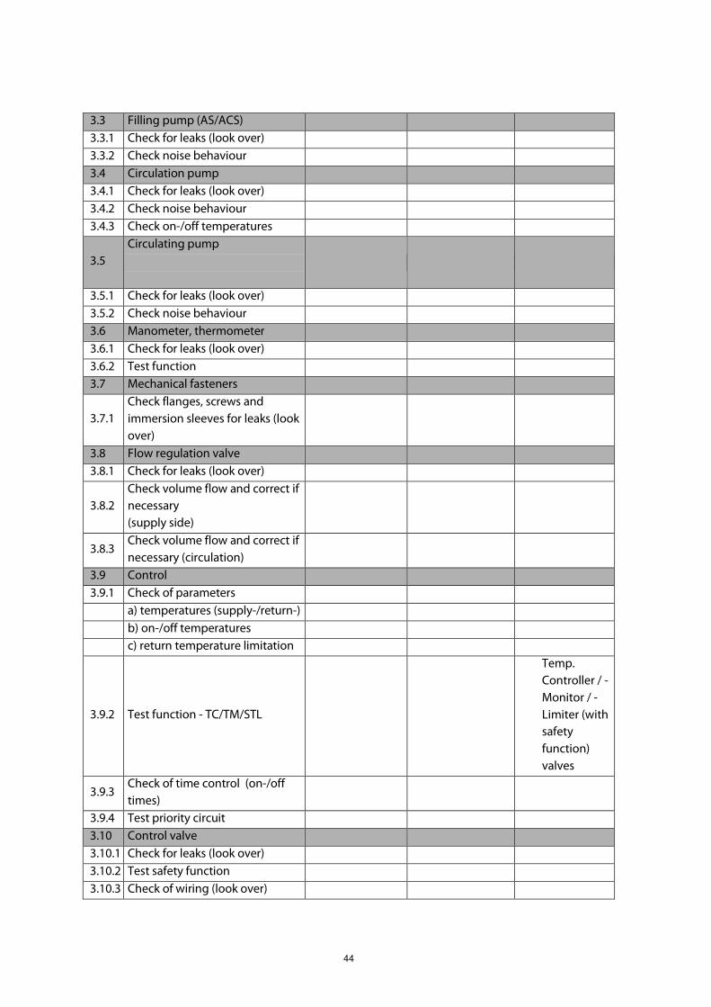
44
3.3 Filling pump (AS/ACS)
3.3.1 Check for leaks (look over)
3.3.2 Check noise behaviour
3.4 Circulation pump
3.4.1 Check for leaks (look over)
3.4.2 Check noise behaviour
3.4.3 Check on-/off temperatures
3.5
Circulating pump
3.5.1 Check for leaks (look over)
3.5.2 Check noise behaviour
3.6 Manometer, thermometer
3.6.1 Check for leaks (look over)
3.6.2 Test function
3.7 Mechanical fasteners
3.7.1
Check flanges, screws and
immersion sleeves for leaks (look
over)
3.8 Flow regulation valve
3.8.1 Check for leaks (look over)
3.8.2
Check volume flow and correct if
necessary
(supply side)
3.8.3 Check volume flow and correct if
necessary (circulation)
3.9 Control
3.9.1 Check of parameters
a) temperatures (supply-/return-)
b) on-/off temperatures
c) return temperature limitation
3.9.2 Test function - TC/TM/STL
Temp.
Controller / -
Monitor / -
Limiter (with
safety
function)
valves
3.9.3 Check of time control (on-/off
times)
3.9.4 Test priority circuit
3.10 Control valve
3.10.1 Check for leaks (look over)
3.10.2 Test safety function
3.10.3 Check of wiring (look over)

45
3.11 Safety valves
3.11.1 Check for leaks
3.11.2 Test function
3.12 Heat exchanger (indirect
connection)
3.12.1 Check for leaks outside (look
over)
3.12.2 Check for leaks inside
Notice: Shut off extraction-,
circulation- and cold water pipes
and relieve pressure. Abrupt
rising pressure on secondary side
indicates leak.
3.13 Storage tank
3.13.1 Check for leaks (look over)
3.13.2 Check anode
3.13.3 Check inside (look over)
3.13.4 Clean sedimentary deposit if
possible
Notice: Log actual values during
inspection in the checklist.
Additional defects, like damaged
electrical equipment or installation
in the domestic connection room
also have to be logged. The
customer has to be informed
immediately to remedy
deficiencies.
B – Space Heating
Pos. Heater curcuit:______
direct indirect
Working
hours
look over
[h]
Working hours
test function
[h]
Remark
2 Room heating
2.1 Pipe system
2.1.1 Check for corrosion (look over)
2.1.2 Check of insulation (look over)
2.1.3 Potential equalisation available
(look over)
2.1.4
Check of fill drain and air escape
valves
(look over)
2.1.5 Check of mounting (look over)
2.1.6 Check air venting

46
2.1.7 Check for leakages
2.2 Shut off - armatures
2.2.1 Test function (practicability)
2.2.1 Check for leaks (look over)
2.3 Dirt trap
2.3.1 Check for leaks (look over)
2.3.2 Check filter, clear filter and if
necessary renew sealing
2.4 Non return valve
2.4.1 Check for leaks (look over)
2.4.2 Test function
Notice: turn off pump, shut off
pump armatures, if return flow
temperature raises, renew the
non return valve.
2.5 Circulating pump
2.5.1 Check for leaks (look over)
2.5.2 Check noise behaviour
2.6 Manometer, thermometer
2.6.1 Check for leaks (look over)
2.6.2 Test function
2.7 Mechanical fasteners
2.7.1
Check flanges, screws and
immersion sleeves for leaks
(look over)
2.8 Weather induced control
2.8.1 Check of parameters
a) temperatures (supply-/return-
/outside)
b) heating curve
c) on-/off temperatures
d) return temperature limitation
2.8.2 Check of time control
a) reduced temperature times
b) summer-/ wintertime
2.8.3 Test function - TC/TM/STL
Temp. Controller /
-Monitor / -
Limiter (with
safety function)
valves
2.9 Control valve
2.9.1 Check for leaks (look over)
2.9.2 Test safety function
2.9.3 Check of wiring (look over)
2.9.4 Test stop position

47
2.10 Heat exchanger (indirect
connection)
2.10.1 Check for leaks (look over)
2.10.2 Check safety valve for leaks (look
over)
a) test function
2.10.3
Log district heating - and
domestic plant return
temperatures (indicates dirt
evaluation of the heat
exchanger)
2.11 Diaphragm type expansion tank
a) Check for leaks (look over)
b) Shut off armature (look over
and test practicability)
c) Check secondary pressure/
nitrogen
Notice: Log actual values during
inspection in the checklist.
Additional defects, such as
damaged electrical equipment or
installation in the domestic
connection room also have to be
logged. The customer has to be
informed immediately to remedy
deficiencies.

48
CHAPTER 7 – HEAT METERING
7.1. General
The Energy Services Directive includes goals concerning the reduction of primary energy
consumption. Proper information about individual energy consumption, for instance based on
metering, is necessary in order to motivate customers into saving energy.
Heat allocators are an additional way of introducing individual metering and are not covered by
these Guidelines. In most countries heat allocators are used in larger buildings with a large
number of flats. The installation and the operation of the system are normally carried out by the
building administration company. The district heating company then has only one main meter
measuring the total consumption of the building.
Heat metering allows for the customer to be invoiced for consumed heat in an accurate
manner. To invoice according to basic data energy, a volume and hour counter is needed. For
temperature-related tariffs such as peak load, flow temperatures are required. The previous
metering principle measures only the accumulated flow, invoicing the m3 consumption, and is
therefore no longer recommended.
Other important issues to be aware of are: security of metering data; conservation of data; and
assurance of the quality of the data. Data logging, of both consumption data and instantaneous
reading values, should be readily available.
The meter is useful for the surveillance of operations in district heating networks and for
monitoring temperatures and flows, thereby contributing to the detection of errors. In this way
the meter data could be used to optimise the operation of the network from an economical
point of view.
It is important to have consumption data in order to keep the customer informed about energy
use and saving opportunities and to assist them in detecting failures. It also allows for
improvements in cooling of the district heating water.

49
Figure 14 Main components of the energy meter
Components:
� the calculator calculating energy consumption;
� the temperature sensor pair in the forward and the return pipe;
� the flow sensor - measuring the amount of district heating water running through the
meter.
Reference to the Measuring Instruments Directive (MID) and standards
The meters (or subassemblies) shall, by complying with all the normative clauses in Parts 1, 2, 4
and 5 of EN 1434, conform to the relevant Essential Requirements of the Measuring Instruments
Directive (MID). For meters with data communication, Part 3 shall also apply.
As required by the MID
A measuring instrument shall be suitable for its intended use, taking into account the practical
working conditions, and shall not require unreasonable demands from the user in order to
obtain a correct measurement result.
In order to ensure that the running meters are working correctly it is necessary to introduce a
control system. The system should be based on a statistical test programme. A
recommendation is given in Section 8.4.3 for the countries that have no national regulations on
this.
The communication system and remote reading of meters should comply with EN 13757.
7.2. Functional Requirements
As required in the MID
The needed measuring range in temperature, temperature difference and flow rate as well as
the maximum admissible working pressure, shall be determined by the distributor or the
person legally designated for installing the meter, so that the meter is appropriate for the
accurate measurement of consumption that is foreseen or foreseeable.
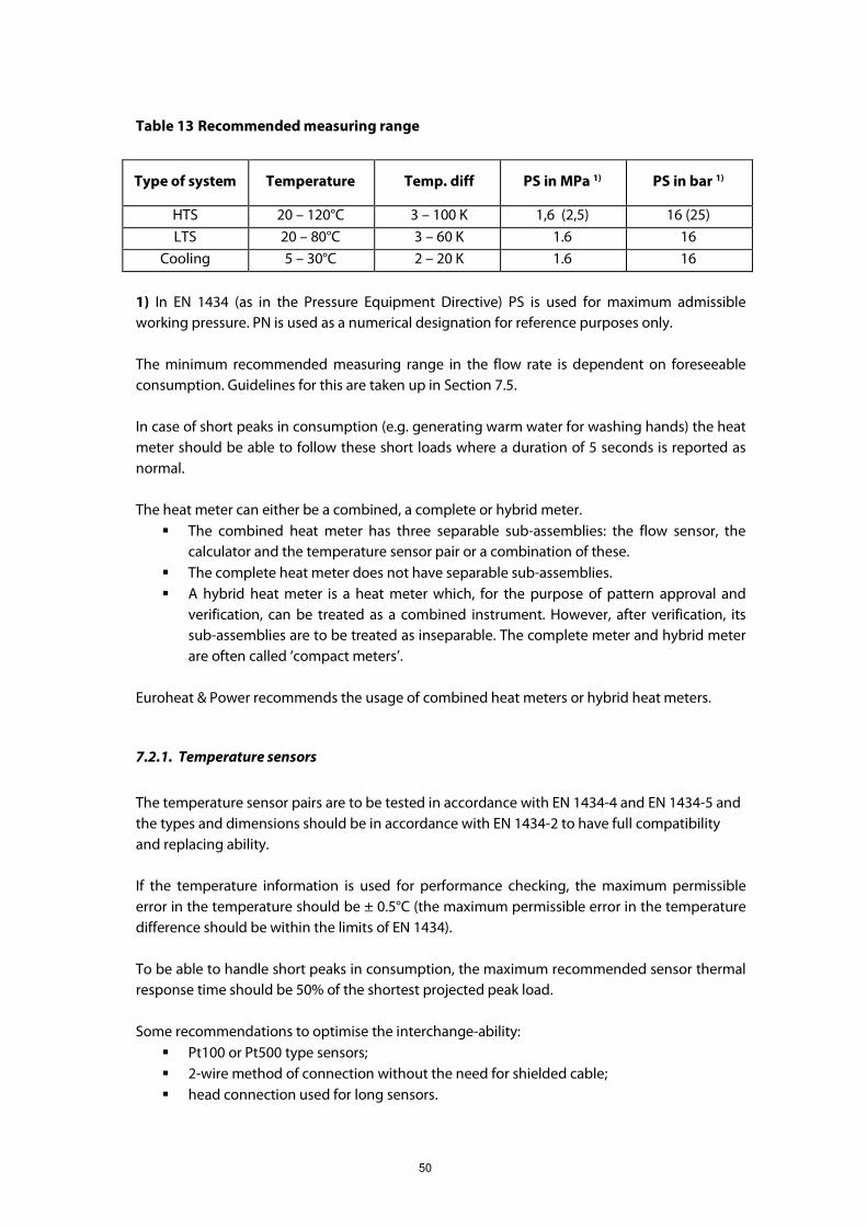
50
Table 13 Recommended measuring range
Type of system Temperature Temp. diff PS in MPa 1) PS in bar 1)
HTS 20 – 120°C 3 – 100 K 1,6 (2,5) 16 (25)
LTS 20 – 80°C 3 – 60 K 1.6 16
Cooling 5 – 30°C 2 – 20 K 1.6 16
1) In EN 1434 (as in the Pressure Equipment Directive) PS is used for maximum admissible
working pressure. PN is used as a numerical designation for reference purposes only.
The minimum recommended measuring range in the flow rate is dependent on foreseeable
consumption. Guidelines for this are taken up in Section 7.5.
In case of short peaks in consumption (e.g. generating warm water for washing hands) the heat
meter should be able to follow these short loads where a duration of 5 seconds is reported as
normal.
The heat meter can either be a combined, a complete or hybrid meter.
� The combined heat meter has three separable sub-assemblies: the flow sensor, the
calculator and the temperature sensor pair or a combination of these.
� The complete heat meter does not have separable sub-assemblies.
� A hybrid heat meter is a heat meter which, for the purpose of pattern approval and
verification, can be treated as a combined instrument. However, after verification, its
sub-assemblies are to be treated as inseparable. The complete meter and hybrid meter
are often called ‘compact meters’.
Euroheat & Power recommends the usage of combined heat meters or hybrid heat meters.
7.2.1. Temperature sensors
The temperature sensor pairs are to be tested in accordance with EN 1434-4 and EN 1434-5 and
the types and dimensions should be in accordance with EN 1434-2 to have full compatibility
and replacing ability.
If the temperature information is used for performance checking, the maximum permissible
error in the temperature should be ± 0.5°C (the maximum permissible error in the temperature
difference should be within the limits of EN 1434).
To be able to handle short peaks in consumption, the maximum recommended sensor thermal
response time should be 50% of the shortest projected peak load.
Some recommendations to optimise the interchange-ability:
� Pt100 or Pt500 type sensors;
� 2-wire method of connection without the need for shielded cable;
� head connection used for long sensors.

51
7.2.2. Flow sensor
The flow sensors are to be tested in accordance with EN 1434-4 and EN 1434-5 and the types
and dimensions should be in accordance with EN 1434-2 to have the full compatibility and
replacing ability.
Depending on the installation possibilities, the flow sensors should be approved to be used in
either of the following ways:
� without any requirements for straight pipes before and after the meter; or
� with the standardized flow conditioner package defined in Annex B of EN 1434-1.
For smaller substations accuracy class 3 should be accepted, but for larger substations class 2 is
recommended.
Depending on the foreseeable variations in thermal load the dynamic flow range (qp/qi) should
be at least 25 or 50. (MID specifies > 10; EN 1434 has the standardized values 10, 25, 50, 100 or
250.)
NOTE:
EN 1434 and MID use the following definitions for flow levels:
� a flow threshold value, under which no registration is allowed.
� qi for minimum flow (over which the sensor is to be within the maximum error limits).
� qp for permanent flow (where the sensor is to be able to work continuous without
exceeding the maximum pressure drop).
� qs for maximum flow (“overrange” where the sensor is to be able to work for shorter
times and be within the error limits).
� for flow rates greater than qs, the behaviour of the meter, e.g. by producing spurious or
zero signals, should be declared by the manufacturer. Flow rates greater than qs are not
to result in a positive error greater than 10 % of the actual flow-rate. Euroheat & Power
recommends that no meters should be selected that indicate zero flow at flow rates
over qs.
There is no standardized relationship between qp and qs and they can have the same value.
The lowest pressure for which the flow sensor is to function should be specified.
Euroheat & Power recommends specifying a “long-life flow sensor” which typically lasts for
more than 5 years.
To be able to handle short peaks in consumption the flow sensors should be classified as “fast
response meter” and the test in 6.4.2.4 of EN 1434-4 should be included at the type testing.
7.2.3. Calculator
The calculator is to be tested in accordance with EN 1434-4 and EN 1434-5.

52
We recommend that the display at least should have at least the following information easily
accessible:
� accumulated energy (basic information);
� accumulated volume;
� temperatures.
Additional values are recommended to be available after some additional display button
operations:
� power;
� flow;
� pulse value;
� operation time;
� error codes;
� baud-rate for data exchange;
� M-bus address;
� peak value of power with timestamp;
� peak flow rate with timestamp.
Heat meter calculators may be fitted with interfaces allowing the connection of supplementary
devices. Such connections are not to modify the metrological qualities of the heat meter.
If short peak loads should be registered correctly, the time interval between the calculations
and measurements of temperatures should be in the same order as or faster than the duration
of the peaks.
Input and output test signals
� A high resolution energy signal should always be provided for automatic and multi-
testing purposes. The resolution should be sufficiently high so that at the lower limit of
temperature difference and/or flow rate, the additional error caused by the energy
signal can be shown to be insignificant. The supplier should state the nominal
relationship between the high-resolution signal and the energy reading.
� The energy signal as specified above should be available either directly at the calculator
connection terminal or at the terminal of a testing adapter as stated in Annex B of EN
1434.
� The test signal should either be pulses with a defined value of pulses/energy increment
or preferably data output, specially defined, or a display with correspondingly high
resolution.
� Pulse output names used at output connections are provided in Annex B of EN 1434.
Batteries
If a heat meter has interchangeable batteries, they should be replaceable without causing
damage to the verification markings. The supplier should declare the lifetime of the batteries.
The lifetime may differ depending on:
� how often the data communication is used;
� the frequency of input pulses from flow sensor and the frequency of calculations.

53
Data-logging
We recommend the calculator to have some data logging functions that can store at least:
� peak values of power and flow with timestamp;
� mean value of flow under a number of periods of about 15 minutes,
� error codes with time stamp.
The data-logging function stores data in an extended memory. All recorded data cannot be
displayed but can be read, reset or programmed through the optical interface or by means of
other communication options.
Durability and reliability
The total lifetime of a calculator should be at least 15 years, and Euroheat & Power recommends
that the in-service life should be at least 10 years if allowed by national regulations and if in
accordance with testing procedures.
7.2.4. Remote reading of data
We recommend that a new calculator should at least have the possibility to install a remote
reading facility. Remote reading of the meters allows surveillance of operations in district
heating networks as well as monitoring temperatures and flows, thus contributing to the
detection of errors. In such way, the meter data could be used to optimise the operation of the
network from an economical point of view.
If the battery lifetime is dependent on the usage of remote reading, this should be specified by
the supplier. Remote reading makes it possible to provide more information and services to the
customers.
7.3. Documentation Requirements
7.3.1. General
As required in the MID
If necessary, the instrument shall be accompanied by operational guidelines. Information shall
be easily understandable and shall include where relevant:
� rated operating conditions;
� mechanical and electromagnetic environment classes;
� the upper and lower temperature limit, whether condensation is possible or not, open
or closed location;
� instructions for installation, maintenance, repairs, permissible adjustments;
� instructions for correct operation and any special conditions of use;
� conditions for compatibility with interfaces, sub-assemblies or measuring instruments.
This means that not only installation instructions but also manuals for testing, setting
parameters, service and necessary testing adapters should be available to the district heating
companies.

54
7.3.2. Compatibility and interfaces between subassemblies
The type of signals between the calculator, the temperature sensors and the flow sensor should
be clearly defined by the supplier, preferably by referring to the standard solutions in EN 1434.
For compatibility between subassemblies, EN 1434 defines a number of input and output
classes for the signals. The most commonly used combinations between the flow sensor and
the calculator are put forward in Table 14 below.
Table 14
Flow sensor output Calculator input
OA: reed or electric switch with no polarity
specified
OC: open collector with specified polarity
IB: “slow” input with pull-up resistor
7.4. Dimensioning of Temperature Sensors
The size of the sensors should be adapted to the size of the pipe so that the sensing element is
situated in the middle of the streaming water.
EN 1434 recommends:
� type DS without pockets with a length of 39 mm for pipes with DN 15 … 25;
� type DL without pockets or PL with pockets with a length of 85, 120 or 210 mm for
larger pipes
o mounted in bend or angled for DN 32 … 50
o mounted perpendicular for DN 65 … 250
Euroheat & Power does not generally recommend the use of pockets, however in connection
with a large substation they may be used.
Most sensors on the market have a sufficient temperature range. See Section 8.2.
7.5. Dimensioning of Flow Sensors
Determining the necessary capacity of a flow sensor depends on the temperature rating and
design of the district heating system, as well as on the system operating conditions. It is also
necessary to know the customer's requirements and consumption characteristics. Once these
parameters and factors are known, it is normally possible to work out what the likely district
heating flow rate will be. In case of replacement of the meter there is good historical data from
which the needed sensor capacity can be determined exactly – see Section 8.5.2.1.

55
In new installations, the energy certificate required by the Buildings Directive can provide a very
good basis for determining the needed capacity.
Data required for determining the needed capacity of flow sensors
The district heating system: Maximum and minimum pressure differences across the
service valves, together with temperature variations in
the system and water quality.
Heat demand: Flow demand for radiators / space heating, with
allowance for any special operating requirements.
Domestic warm water: Flow demand for domestic warm water production.
Control: Valve sizes and response times, with allowance for any
special operating requirements / strategies.
Flow sensors: Flow sensors' measurement ranges (qi – qp), with
pressure drop at qp, behaviour over qs, etc.
7.5.1. The district heating system
Analyse the operating conditions in terms of production and distribution conditions (pressure
drops and temperature levels) that can affect the meter. It is essential to have pressure drop
diagrams for the flow sensors for this.
7.5.2. Heat demand
There can never be totally accurate model values for heating and domestic warm water
requirements as each building is different: it is necessary to know what the consumption
patterns are in each. Historically, the trend has been to install flow sensors that are too large,
but as knowledge of domestic warm water and space heating demands and capacity
determination improves, it becomes possible to use smaller flow sensors. It is better
occasionally to choose flow sensors that are too small, rather than always selecting sensors that
are too large.
In some situations a flow regulator could be used to limit the flow.
Check the data for the calculations determining the necessary capacity of the district heating
substation unit itself. The thermal power value used for determining the necessary meter
capacity is to stand in reasonable relation to the actual demand.
An upper limit value of 100 W/m2 can be used for some older residential buildings, with a value
of 40 W/m2 being more suitable for more energy-efficient buildings. The size of this limit value
affects the choice of meter.
The following rough calculation can be used to check the power demand:
Heat load [kW] = Heated area [m2] *x [W/m2]/1000
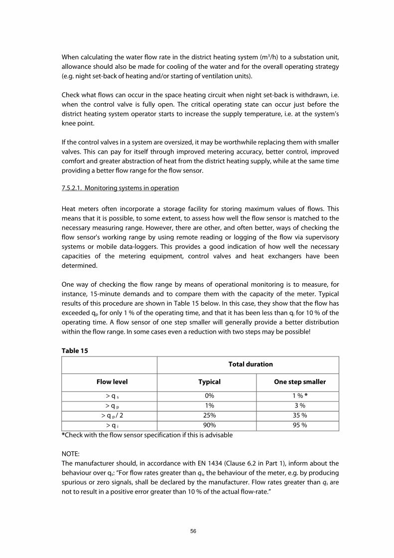
56
When calculating the water flow rate in the district heating system (m3/h) to a substation unit,
allowance should also be made for cooling of the water and for the overall operating strategy
(e.g. night set-back of heating and/or starting of ventilation units).
Check what flows can occur in the space heating circuit when night set-back is withdrawn, i.e.
when the control valve is fully open. The critical operating state can occur just before the
district heating system operator starts to increase the supply temperature, i.e. at the system’s
knee point.
If the control valves in a system are oversized, it may be worthwhile replacing them with smaller
valves. This can pay for itself through improved metering accuracy, better control, improved
comfort and greater abstraction of heat from the district heating supply, while at the same time
providing a better flow range for the flow sensor.
7.5.2.1. Monitoring systems in operation
Heat meters often incorporate a storage facility for storing maximum values of flows. This
means that it is possible, to some extent, to assess how well the flow sensor is matched to the
necessary measuring range. However, there are other, and often better, ways of checking the
flow sensor's working range by using remote reading or logging of the flow via supervisory
systems or mobile data-loggers. This provides a good indication of how well the necessary
capacities of the metering equipment, control valves and heat exchangers have been
determined.
One way of checking the flow range by means of operational monitoring is to measure, for
instance, 15-minute demands and to compare them with the capacity of the meter. Typical
results of this procedure are shown in Table 15 below. In this case, they show that the flow has
exceeded qp for only 1 % of the operating time, and that it has been less than qi for 10 % of the
operating time. A flow sensor of one step smaller will generally provide a better distribution
within the flow range. In some cases even a reduction with two steps may be possible!
Table 15
Total duration
Flow level Typical One step smaller
> q s 0% 1 % *
> q p 1% 3 %
> q p / 2 25% 35 %
> q i 90% 95 %
*Check with the flow sensor specification if this is advisable
NOTE:
The manufacturer should, in accordance with EN 1434 (Clause 6.2 in Part 1), inform about the
behaviour over qs: “For flow rates greater than qs, the behaviour of the meter, e.g. by producing
spurious or zero signals, shall be declared by the manufacturer. Flow rates greater than qs are
not to result in a positive error greater than 10 % of the actual flow-rate.”
57
General info from EN 1434 about qs: “5.3.1. The upper limit of the flow-rate, qs, is the highest
flow-rate, at which the heat meter shall function for short periods (< 1h / day; < 200 h / year),
without the maximum permissible errors being exceeded.”
7.5.2.2. Heat demand for industrial premises and office buildings.
Maximum demands for ventilation, space heating and domestic warm water production do not
normally occur simultaneously in industrial premises or office buildings. When deciding on the
necessary measurement range for the flow sensor, it is advisable to start from the expected
highest demand flow rate for any one of these loads.
If the premises are normally heated by both radiators and tempered ventilation air, the two
loads should be added and used as a guide when calculating and selecting the meter's qp rating
(this does not apply for unusual loads such as swimming pools etc.).
Complicated installations should be fitted with ultrasonic flow sensors, with a capacity as
determined by the likely aggregated load. In such cases, qs at the likely maximum load could
perhaps be used. This would be the case, for example, for process plants that are heated by
ventilation units, requiring a rapid temperature rise in the mornings.
If brief flow peaks in excess of qs occur, ultrasonic flow sensors are not affected in the same
manner as are mechanical flow sensors. Some ultrasonic flow sensors continue measuring in
the overload range. Check the flow range after installation by logging the flow, or by using an
integrator that registers maximum flows.
Euroheat & Power recommends choosing one of the higher dynamic ranges specified in EN
1434.
7.5.3. Selection of suitable flow sensors
Different types of meters have different working ranges and different requirements in respect of
the working environment and it is these factors that determine the type of meter to be used.
As opposed to mechanical devices, ultrasonic flow sensors have no problems with continuous
measurement at their maximum flow rates, which means that the fitting size can often be
smaller. However, the pressure drop across the meters can vary, depending on their design, and
so the maximum permissible pressure drop should be considered.
After obtaining details on the particular factors governing the type of flow sensor needed, it is
necessary to identify the specific type and rating etc. of the sensor. The required measurement
range and pressure drop across the flow sensor are the decisive factors, and so it is important to
obtain full data from the supplier when purchasing meters.
For buildings with around 10 to 20 apartments, the capacity of flow sensors in the district
heating return connection can be determined on the basis of the domestic warm water flow
requirement, while for larger buildings the capacity can be determined on the basis of the flow
58
requirement for delivery of the building space heating load. The design flow rate should be
close to qp, or a little higher for static sensors.
Provided that the pressure drop across the flow sensor does not exceed 25 kPa, a few sizes of
flow sensors will suffice for metering heat supplies to buildings containing up to 100
apartments.
Examples of standard stock flow sensors will provide coverage as follows
qp = 0,6 m3/h from one detached house up to 5 apartments
qp = 1,0 m3/h up to 25 apartments
qp = 2,5 m3/h up to 65 apartments
qp = 6,0 m3/h up to 100 apartments
The values in the example are related to the lower dimensioning slope in chapter 2.7.1 Figure 4.
7.6. Installation of Heat Meters
7.6.1. Environmental influences
7.6.1.1. Environmental classification
In accordance with EN 1434, a heat meter is to conform to one or more environmental
classifications according to its application. For larger substations Euroheat & Power
recommends using class C.
7.6.1.2. Protection classification
According to EN 1434 the minimum forms of enclosure protection is to be IP54 for equipment
that is to be installed into pipe work and IP52 for other enclosures
7.6.1.3. Flow profile at the metering position
For our purposes, the term 'flow profile' is taken to mean: the velocity distribution across a
cross-section of liquid flowing through a pipe. The shape of the flow profile at the metering
position has a very considerable effect on the performance of all types of flow meters. Meters
that measure the flow velocity at only a part of the cross-sectional area, such as single-beam
ultrasonic meters, are very dependent on the flow profile over the metering range being
representative of the full flow area. Different forms of potential interference affect the flow
profile in different ways, and the distance between such interference sources and the meter is
very important.
7.6.2. Planning the meter position
The meter can be placed on either the forward or return pipe depending on the temperature
level. Piping arrangements, the positions of components and the design of the electrical
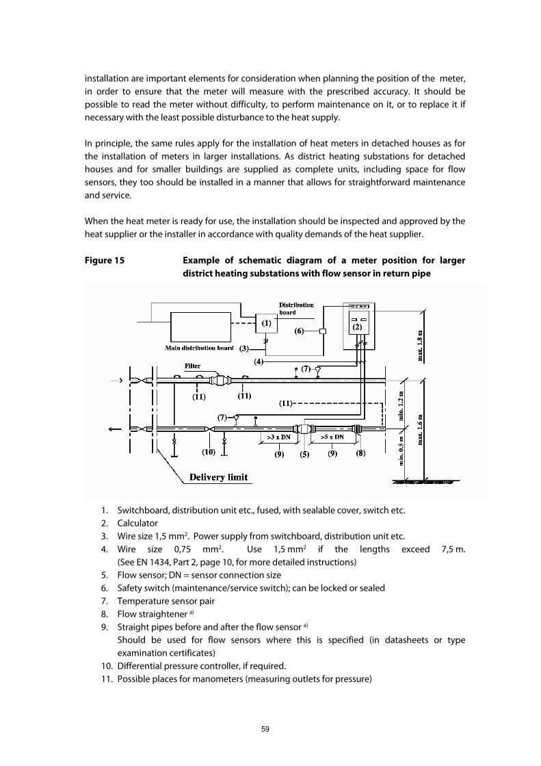
59
installation are important elements for consideration when planning the position of the meter,
in order to ensure that the meter will measure with the prescribed accuracy. It should be
possible to read the meter without difficulty, to perform maintenance on it, or to replace it if
necessary with the least possible disturbance to the heat supply.
In principle, the same rules apply for the installation of heat meters in detached houses as for
the installation of meters in larger installations. As district heating substations for detached
houses and for smaller buildings are supplied as complete units, including space for flow
sensors, they too should be installed in a manner that allows for straightforward maintenance
and service.
When the heat meter is ready for use, the installation should be inspected and approved by the
heat supplier or the installer in accordance with quality demands of the heat supplier.
Figure 15 Example of schematic diagram of a meter position for larger
district heating substations with flow sensor in return pipe
1. Switchboard, distribution unit etc., fused, with sealable cover, switch etc.
2. Calculator
3. Wire size 1,5 mm2. Power supply from switchboard, distribution unit etc.
4. Wire size 0,75 mm2. Use 1,5 mm2 if the lengths exceed 7,5 m.
(See EN 1434, Part 2, page 10, for more detailed instructions)
5. Flow sensor; DN = sensor connection size
6. Safety switch (maintenance/service switch); can be locked or sealed
7. Temperature sensor pair
8. Flow straightener a)
9. Straight pipes before and after the flow sensor a)
Should be used for flow sensors where this is specified (in datasheets or type
examination certificates)
10. Differential pressure controller, if required.
11. Possible places for manometers (measuring outlets for pressure)

60
7.6.3. Suitable and unsuitable positions for flow sensors
Figure 16
A. Suitable position for most types of meters
B. This position works well for inductive and ultrasonic meters
C. Unsuitable position, as bubbles can collect to form air pockets
D. Unsuitable position, as bubbles can collect to form air pockets
E. Valves should not be fitted immediately upstream of the meters; the distance should
consider the meter type
F. A meter should not be positioned before a pump
G. Meters should be positioned well away from bends in two planes
Turbine sensors should be installed horizontally with a vertical turbine axis. The flow direction
should be respected.
Vertical Woltman sensors should be installed in horizontal pipes with the Woltman axis vertical.
The vertical Woltman meters should be installed at the lowest point of the pipe work in order to
avoid the risk of trapped air in the meter.
7.6.4. Piping installation
� The heat supplier generally installs the flow sensor, calculator and temperature sensors.
� The main service valves for district heating substations are normally positioned about
1,0 - 1,8 m above floor level. If they are installed outside the substation room, fit
separate valves as shown by the dotted lines in the schematic diagram. In case of long
pipe runs, too, shut-off valves fitted upstream of the flow sensor should be fitted
outside the straight length of the pipe run. Valves fitted in pressure measurement pipes
should have welded connections. The flow sensor should be positioned so that it is
easily accessible, at least 15 cm from the wall and with an unobstructed space of at
least 0,7 m in front of it.
61
� If a meter is to be correctly installed, the piping contractor needs to know the size of the
flow sensor's connection flanges. This information should be provided by the heat
supplier.
� To accept all EN 1434 approved sensors there should be, directly upstream of the
meter, a thin (0,12xDN) flow straightener plate followed by an inlet pipe without flow
disturbances with a length of 5xDN (min.). Behind the meter, an outlet pipe of 3xDN is
needed.
NOTE: See Annex B of EN 1434-1 for details.
� Thoroughly flush the circuit in which the flow sensor is to be installed in order to
remove dirt before fitting the sensor. Clean the filter, if there is one.
� In order to minimise the risk of damage, the heat meter should be protected from
shocks and vibrations originating from its surroundings.
� The flow sensor should not be exposed to unnecessary mechanical loading caused by
stresses in the pipes or connections.
� Pipes connecting to the flow sensor should be fitted with pipe supports.
7.6.4.1. Details for temperature sensors
The sensors should be positioned in the centre of the flow. A sensor should be mounted in a
welded-in boss or pipe fitting, either:
� perpendicular to the pipe;
� in an angle of about 45 º with the tip against the flow direction;
� in a bend with the tip against the flow direction.
The temperature sensors should be fitted in the district heating supply pipes in easily accessible
positions. The pipes in which the sensors are installed should be of the same size and should
have very similar flow profiles. The two sensors should be installed in a similar manner in each
pipe. Adjust the length of the pipe sleeve so that the actual sensing elements of the sensors are
in the centre of the pipe.
The insulation should not cover the threaded connection of the pocket or sensor due to leakage
risks.
7.6.5. Electrical installation
� Heat meters requiring a mains connection should be connected in accordance with all
applicable electrical regulations.
� Mains power supplies should be protected against accidental interruption. A good
quality sealable means of disconnection should be provided for use when it is
necessary to disconnect the supply to the meter in order to deal with electrical
problems or when performing service work.
� Signal wires should not be run immediately adjacent to power cables and should be
secured separately. Measurement signal cables should be separated by at least 50 mm
from other cables such as mains supply cables, low voltage supply cables and data
communication cables, and should be independently supported.

62
� Mains and external signal cables longer than 10m should, in areas where lightning is
frequent, be protected with an external lightning surge protection at the cable
entrance to the building.
� Each signal cable between the temperature sensors and the calculator should have one
continuous length, without joints. For two-wire connections, the cables should be of
the same length.
� It should not be possible to disconnect signal connections between parts of a heat
meter installation, either accidentally or without authorization.
7.6.6. Identity checking
Before using the meter, a check should be made to ensure that the correct meter has been
installed, by comparing the manufacturer's type and size numbers with the capacity data and
system specification. Follow this by checking that the meter displays the correct certification
symbol. If combination meters are in use, each part of the meter should display its own
certification symbol. Check that the documentation for the fitted meter corresponds to its
certificate and enter the details in the heat supplier's meter list.
7.6.7. Installation inspection
The following points should be checked by duly authorised persons:
� that the flow sensor is correctly positioned and orientated, and that it is connected and
installed in accordance with the schematic diagram for the meter installation;
� that the meter is installed at a safe distance from possible sources of electromagnetic
interference (switchboards, electric motors, fluorescent lights);
� that, when so specified, the meter is correctly earthed;
� that all parts of the meter work when the heating system is started;
� that the meter is correctly programmed;
� that the meter seals are intact;
� that the power supply and wiring are correctly installed, for both mains operation
and/or battery operation;
� that the temperature sensors are correctly installed;
� that any accessories are correctly installed, in accordance with the meter supplier's and
heat supplier's instructions;
� that the communication unit is installed, and that the transmitted measured values are
the same as the actual measured values.
The results of the above inspections should be recorded.

63
7.7. Evaluation of Conformity with the MID Requirements
Since 31 October 2006, MID has replaced the earlier national regulations. MID has to be
implemented in current national regulations for meters (or sub-assemblies) after 31 October
2006. Before use, meters need to be subjected to a conformity assessment procedure, which
replaces the earlier procedures of pattern approval and initial verification. It consists of the
combinations of modules described in Annexes B, D, F and H1 of the MID. The manufacturer has
free choice of the modules (B+D or B+F or H1). Only Module F requires verification to be made
outside the manufacturer.
The essential conditions of MID contain many metrological requirements specified in Annex I
and some more details for heat meters in Annex MI-004. There are also more general
requirements such as:
� A measuring instrument shall be suitable for its intended use, taking into account the
practical working conditions, and shall not require unreasonable demands from the
user in order to obtain a correct measurement result.
� A measuring instrument shall be robust and its constituent materials shall be suitable
for the conditions in which it is intended to be used.
MID has detailed requirements for the manufacturer, as stated at the beginning of the MID text:
“The responsibilities of the manufacturer for compliance with the requirements of this Directive
should be specifically stated.”
To make the initial verification in a testing laboratory connected to the manufacturer, the
manufacturer should have an approved quality system for production and final testing.
Alternatively, the final testing should be done by an approved testing institution independent
of both the manufacturer and the user.
There are also some detailed requirements for instrument users. Governmental authorities
should ensure that the appropriate measuring range for a heat meter will be “determined by
the heat supplier or the person legally designated for installing the meter, so that the meter is
appropriate for the accurate measurement of consumption that is foreseen or foreseeable”
(MID Annex MI-004 §8). This means the buyer should use the correct specifications. Such
specifications should include dimensions and other properties to ensure that the meter fits the
intended installation. The specification should also be used when dimensioning the sites where
the meter is to be installed so that standardised meter components will fit.
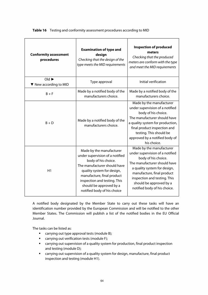
64
Table 16 Testing and conformity assessment procedures according to MID
Conformity assessment
procedures
Examination of type and
design
Checking that the design of the
type meets the MID requirements
Inspection of produced
meters
Checking that the produced
meters are conform with the type
and meet the MID requirements
Old ►
▼ New according to MID Type approval Initial verification
B + F Made by a notified body of the
manufacturers choice.
Made by a notified body of the
manufacturers choice.
B + D Made by a notified body of the
manufacturers choice.
Made by the manufacturer
under supervision of a notified
body of his choice.
The manufacturer should have
a quality system for production,
final product inspection and
testing. This should be
approved by a notified body of
his choice.
H1
Made by the manufacturer
under supervision of a notified
body of his choice.
The manufacturer should have
quality system for design,
manufacture, final product
inspection and testing. This
should be approved by a
notified body of his choice
Made by the manufacturer
under supervision of a notified
body of his choice.
The manufacturer should have
a quality system for design,
manufacture, final product
inspection and testing. This
should be approved by a
notified body of his choice.
A notified body designated by the Member State to carry out these tasks will have an
identification number provided by the European Commission and will be notified to the other
Member States. The Commission will publish a list of the notified bodies in the EU Official
Journal.
The tasks can be listed as:
� carrying out type approval tests (module B);
� carrying out verification tests (module F);
� carrying out supervision of a quality system for production, final product inspection
and testing (module D);
� carrying out supervision of a quality system for design, manufacture, final product
inspection and testing (module H1).

65
Notified bodies are to be independent of any designer, manufacturer, supplier, installer or user
of the measuring instrument that they inspect and any of their authorised representatives.
7.7.1. Examination of type and design
The type and design examination is to include the type testing procedure in EN 1434-4 carried
out under the responsibility of the notified body. The checklist in Annex A of
EN 1434-4 should be followed to ensure that the specific requirements are fulfilled.
7.7.2. Inspection of produced meters
Each individual meter, or sub-assembly, is to pass, as part of the conformity assessment
procedure, the procedure in EN 1434-5 under the responsibility of the notified body.
NOTE:
Specifying meters with a reference to a European Standard does not contradict the Measuring
Instruments Directive or the Procurement Procedures Directive (2004/17/EC).
For meters with type approvals older than 21 October 2006, the old national regulations are still
in force. However, since nearly all recent national regulations were based on EN 1434, the
verification procedure of EN 1434-5 can also be used here.
7.7.3. Control systems
A control system for monitoring the quality of installed meters should be considered as a must.
If not prescribed differently by the national regulations, the following procedure is
recommended as a minimum.
The control system works through the statistical control of several meters. These include meters
/ sub-assemblies that are:
� installed within a year;
� of the same type from the same meter supplier;
� of the same flow sensor size;
� comparable in terms of water quality and operating parameters.
The first control should be within 6 years of installation.
� If the result inside the error limits as specified in EN 1434, the remaining meters can be
left in the installation for an additional period of 6 years.
� If the result is accepted as being inside the double error limits as specified in EN 1434,
the remainder can be left in the installation for an additional 3 years before the next
check.
� If the result is rejected as being outside the double error limits as specified in EN 1434
the entire lot has to be taken out for re-verification within a year and the next control
for that lot of meters should be within the next 5 years.
� Meters taken out for this statistical control should be re-verified before reinstallation.
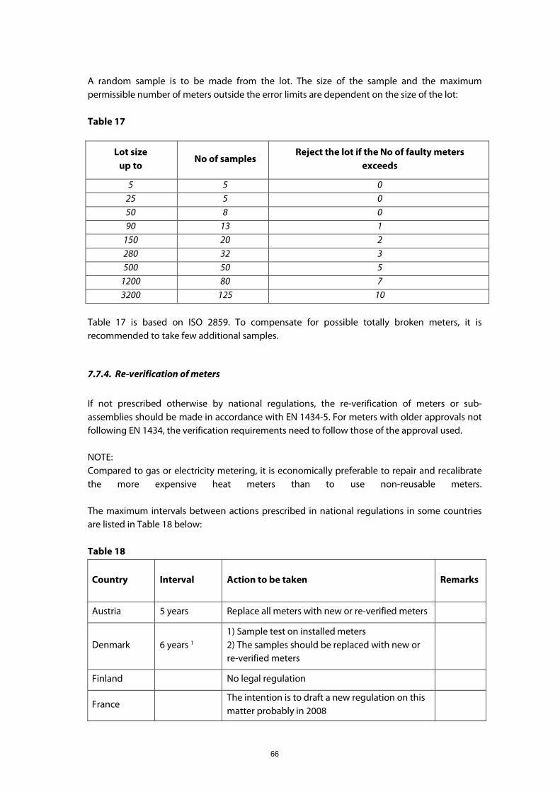
66
A random sample is to be made from the lot. The size of the sample and the maximum
permissible number of meters outside the error limits are dependent on the size of the lot:
Table 17
Table 17 is based on ISO 2859. To compensate for possible totally broken meters, it is
recommended to take few additional samples.
7.7.4. Re-verification of meters
If not prescribed otherwise by national regulations, the re-verification of meters or sub-
assemblies should be made in accordance with EN 1434-5. For meters with older approvals not
following EN 1434, the verification requirements need to follow those of the approval used.
NOTE:
Compared to gas or electricity metering, it is economically preferable to repair and recalibrate
the more expensive heat meters than to use non-reusable meters.
The maximum intervals between actions prescribed in national regulations in some countries
are listed in Table 18 below:
Table 18
Country Interval Action to be taken Remarks
Austria 5 years Replace all meters with new or re-verified meters
Denmark 6 years 1
1) Sample test on installed meters
2) The samples should be replaced with new or
re-verified meters
Finland No legal regulation
France The intention is to draft a new regulation on this
matter probably in 2008
Lot size
up to No of samples
Reject the lot if the No of faulty meters
exceeds
5 5 0
25 5 0
50 8 0
90 13 1
150 20 2
280 32 3
500 50 5
1200 80 7
3200 125 10

67
Germany 5 years2
1) Replace all meters with new or re-verified
meters
2) Sample check on the replaced meters
Italy
Poland 5 years Replace all meters with new or re-verified meters
Slovakia 4 years Replace all meters with new or re-verified meters
Slovenia 5 years Replace all meters with new or re-verified meters
Sweden 5-10 years1
1) Replace all meters with new or re-verified
meters
2) At least a sample check on the replaced
meters
Switzerland 5 years 3 Replace all meters with new or re-verified meters
UK -- No legal regulation
1. the result of sample tests may shorten the interval
2. the result of sample tests may increase the interval
3. an increase of the verification period is only possible for heat distributors that can
demonstrate an appropriate survey procedure of the meters installed in their network
7.8. Lifetime Cost
The examples in Table 19 below specify lifetime costs. Three different scenarios based on 2006
figures from Helsinki. It might be helpful to insert one’s own figures.
Table 19
Scenario
The quality of the DH water, the
installation and the meters allow a
technical life time for the meter of
The national regulations
prescribe
1 at least 15 years the use of sample check to verify
that the meters could be used for
another period
2 at least 15 years a re-verification every 5th year
3 shorter than 10 years a re-verification every 5th year

68
Year Scenario 1 €/meter Scenario 2 €/meter Scenario 3 €/meter
0 + Investment + Installation + Putting into use + *)
567 240 26
+ Investment + Installation + Putting into use + *)
567 240 26
+ Investment + Installation + Putting into use + *)
567 240 26
5 + Sample test + Reinstallation of sampled units + *)
17 9 26
+ Re-verification without any renovation work + Installation + *)
200 108 26
+ Re-verification with renovation OR new meter + Installation + *)
284 108 26
10 + Sample test + Reinstallation of sampled units + *)
17 9 26
+ Re-verification without any renovation work + Installation + *)
200 108 26
+ Re-verification with renovation OR new meter + Installation + *)
284 108 26
15 + Sample test + Reinstallation of sampled units + *)
17 9 26
+ Re-verification without any renovation work + Installation + *)
200 108 26
+ Re-verification with renovation OR new meter + Installation + *)
284 108 26
Total costs per year
989 /15 = 66
1835 /15 =
122
2087 /15 =
139
* Each year there will be a cost for repair of some meters broken down during the
year (2% per annually?).